

Page 1

SDA-7200
Multi-Channel Amplier
Page 2

JBL SYNTHESIS SDA-7200 Introduction/Features/Installation
TABLE OF CONTENTS
Important Safety Precautions .......................................................... 2
Introduction & Feature Highlights ..................................................... 3
Installation & Setup ......................................................................... 3
Installation Considerations........................................................... 3
Front Panel Controls & Indicators ................................................ 4
Rear Panel Connections and Controls.......................................... 5
Connections and Configuration ................................................... 6
Operation ....................................................................................... 7
Troubleshooting & Maintenance....................................................... 8
Specifications ................................................................................. 8
INTRODUCTION
Thank you for purchasing a Synthesis SDA-7200 Digital Power Amplifier. You now have at
your command a unique product that has been designed to deliver the best possible sonic
performance regardless of the content being played, whether it is the latest blockbuster movie,
a major sporting event or your favorite music.
Although the SDA-7200 has been developed to complement JBL Synthesis products it is equally
at home when connected to any high-quality processor or an external EQ system connected to
your surround processor. Its high-power design also means that it has the flexibility to power
Synthesis speakers or virtually any high-quality speaker system from small in-ceiling speakers to
the largest floor standing models. Of course, regardless of the speakers, the SDA-7200 delivers
the performance JBL has been known for in close to 75 years of creating cinema sound.
Welcome to the Synthesis family, we wish you many years of listening pleasure!
FEATURES
• Cutting-edge digital amplifier design
• High efficiency and dual-speed fans for cool, quiet operation
• Short-circuit and thermal protection circuitry
• Music Sense circuitry and low voltage trigger connection for automatic turn-on
• Front-panel LED indicators for individual channel status
• Binding post terminals accommodate large gauge speaker cable
• Removable IEC power cord
INSTALLATION AND SETUP
INSTALLATION CONSIDERATIONS
• To ensure optimal performance, please pay attention to the instructions in this manual.
• Install the SDA-7200 on a solid, flat, level surface that is dry, well-ventilated and out of
direct sunlight.
• Do not place the SDA-7200 directly on a carpeted surface or cover any of the
ventilation holes.
• Do not install the SDA-7200 on a surface that is unstable or unable to support all four feet.
• Do not install it directly above another product, and do not put another product directly on
top of the SDA-7200.
• Do not expose the SDA-7200 to high temperatures or humidity, steam, smoke or excessive
dampness or dust.
WHAT’S IN THE BOX
Your new SDA-7200 includes the items listed below. If anything is missing please contact your
dealer or installer before contacting JBL Synthesis as they may have used it to install you new
product:
• AC Power Cord
• Trigger Cable
• Right and Left “rack ears” and the mounting screws used to install them to your SDA-7200.
2
-
-
Page 3
JBL SYNTHESIS SDA-7200 Front Panel Controls
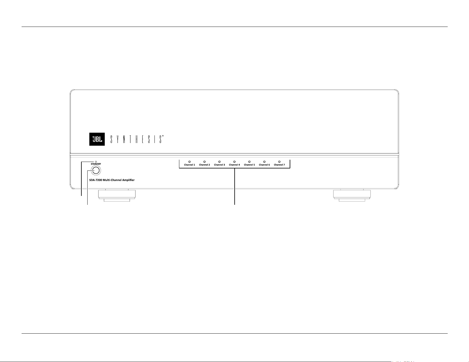
FRONT PANEL CONTROLS AND INDICATORS
Standby
Indicator
Standby/
On Switch
Standby Indicator: This LED indicator is red when the SDA-7200 when AC mains power is
applied and the rear panel Master Power Switch is turned on. It will turn blue when the unit is
turned on.
Standby/On Switch: This switch is only active when the Audio Sense switch on the rear panel is
set to the right pointing towards “Off” and there is no cable connected to the Trigger Input Jack.
As shipped from the factory this switch does not operate; this is normal and is not a problem
with your amplifier. To activate this switch make certain that the Audio Sense Switch in the rear
panel is set to the OFF position (pointing to the right) and that there is no cable connected to the
Trigger Input Jack.
Channel Operation
Indicators
Channel Operation Indicators: These indicators are off when the SDA-7200 is in the Standby
mode and will briefly flash red and then turn blue when the SDA-7200 is turned.
During normal operation if all, or any, of the lights turns red that indicates a possible problem
with your amplifier. Consult the Troubleshooting Guide on Page n for more information on
correcting any faults.
3
-
-
Page 4

JBL SYNTHESIS SDA-7200 Rear Panel Connections
REAR PANEL CONNECTIONS
Input Jacks
Output Terminals
Input Jacks: Connect these jacks to the audio outputs of your surround processor or external EQ.
NOTE: All channels are equal, so you may connect any output channel position from your
processor or EQ to any of the inputs.
Output Terminals: Connect these terminals to the wires running from the amplifier to your
speakers. Always be careful to observe proper polarity by connecting the positive/red outputs
on the top row of the SDA-7200 to the positive/red terminals on the speakers and the negative/
black terminals on the bottom row of the SDA-7200 to the negative/black terminal speakers.
Trigger Input Jack
CAN ICES-3(B)/ NMB-3(B)
3050166
Audio Sense Switch
Fuse Receptacle
Master Power
Switch
1200W
~
100-120V/200-240V 50/60Hz
AC Power Cord
Receptacle
AC Power Cord Receptacle: Connect the AC power cord supplied with the unit to this
receptacle, and connect the power cord plug to an AC outlet.
Fuse Receptacle: If the amplifier is totally inoperative it may be due to a blown fuse. Before
replacing the fuse it is important that the Master Power Switch be placed in the Off position.
IMPORTANT NOTE: To assure continued safety and proper operation it is critical that
fuse be replaced with one that is of the exact same type and rating as the original. If you
have any questions do not replace the fuse yourself and contact your dealer or installer.
NOTE: When using a bare wire connection always make certain that the wire strands from any
speaker connection do not touch another or any part of the rear panel and that the positive and
negative cables do not touch each other.
NOTE: After connecting speaker wire to the terminals hand tighten the speaker terminal nut. DO
NOT use tools or excessive force.
Trigger Input Jack: Connect the trigger output of a compatible product capable of feeding
5VDC to 16VDC to this jack when automatic amplier turn on/off is desired. Use the Trigger Cable
supplied with the amplier or any cable with 3.5mm mono connectors on each end.
NOTE: When a cable is connected to this jack the Front Panel Standby/On Switch 3 is disabled.
Master Power Switch: Turn this switch to the On position to operate the product. When it
is in the Off position the amplifier is disconnected from AC power and will not respond to any
controls. In normal operation this switch may be left On, but it should be turned Off when the
unit will not be used for an extended period of time such as a vacation.
4
-
-
Audio Sense Switch: This switch determines the method by which the SDA-7200 will be
placed in the On, or active operational, condition.
• The SDA-7200 is shipped with the switch is set to the left, or ON. In this position the unit will
automatically turn on when an audio signal is present at any of the Input Jacks.The unit will
automatically turn off approximately 30 minutes after an audio signal is no longer present.
• When the switch is set to the right, or OFF, the amplifier is the manual control mode and will
turn on when the front panel front panel Standby/On Switch is pressed as long as a Trigger
Cable is not connected.
NOTE: The Audio Sense function is disabled and the front panel Standby/On switch is inactive
when a cable is connected to the Trigger Input Jack.
Page 5

JBL SYNTHESIS SDA-7200 Connections and Conguration
CONNECTIONS AND CONFIGURATION
SAFETY NOTE: When making connections between the SDA-7200 and a surround
processor or EQ system be certain that both the SDA-7200 and other device feeding
it are turned off. To assure that there will be no unwanted signal transients that can
damage equipment or speakers, it is always best to unplug all equipment before
making any connections.
AUDIO SIGNAL CONNECTIONS
AUDIO INPUT CONNECTIONS
Audio input connections for the SDA-7200 are simple and straight-forward: Connect the output
of the surround processor or EQ system.
All channels are equal, so you may connect any channel output of your surround processor or
EQ system to any input on the amplifier. We recommend the following connection scheme, but
whichever output channel is connected to a given input on the amplifier we suggest you make a
list of those connections so that the speakers may be properly connected:
Channel 1: Front Left
Channel 2: Center
Channel 3: Front Right
Channel 4: Left Surround
Channel 5: Right Surround
Channel 6: Left Back Surround
Channel 7: Right Back Surround
When making connections make certain to gently, but firmly insert the “RCA” type plugs them
into the jacks on the back of the SDA-7200. Loose connections can cause intermittent sound
and may damage your speakers.
SPEAKER WIRE CONNECTIONS
Regardless of the channel configuration used, the final step of the installation process is to
connect the amplifier to your speakers, using high quality cable. The SDA-7200 is equipped with
binding post terminals that accept bare wire, spade lugs or banana type plugs.
To assure that the high quality audio produced by your SDA-7200 is carried to your speakers
without loss of clarity or resolution, we recommend that you use high quality speaker cable.
Many brands of cable are available, and the choice of cable may be influenced by the distance
between your speakers and the amplifier, the type of speakers you use, personal preferences,
and other factors. Your dealer or installer is a valuable resource to consult in selecting the proper
cable for connections between your amplifier and speakers.
First, loosen the knobs on the Output Terminals until the pass-through hole is visible. Next, pass
the cable through the hole making certain that you place the “positive” cable side through the
top connector and the “negative” cable through the bottom connector. Make certain that the
wire strands from one cable do not touch another or the back panel of the amplifier. When the
connections are made, twist the cap back so that the connection is secured, but do not over
tighten or use tools.
If you are using spade lugs, connect them to the wire using the manufacturer’s instructions, and
then loosen the caps on the speaker terminals. Place lugs between the plastic cap and the back
of the terminal, making sure to observe proper polarity. Hand tighten the knobs when finished.
When banana plugs are permitted, connections may be made by simply inserting the jack afxed
When using banana plugs simply push them into the holes at the back of the knobs on the Output
Terminals into the hole provided on the rear of the colored screw caps on the binding posts. Before
using banana type jacks make certain that the plastic screw caps are rmly tightened down by
turning them in a counter clockwise direction until they are snug against the chassis.
Finally, connect the wires to the speakers, being certain to observe proper polarity. Make note
of the channel connections from your processor or or EQ system so that each channel output is
connected to the proper speaker location.
CONFIGURATION
The SDA-7200 will automatically turn on in one of three ways. Depending on your specific
application, the unit may be turned on manually using the front-panel Standby/On Switch, via
automatic sensing of an audio input source or in response to a low voltage trigger signal.
For manual operation, simply move the Audio Sense Switch to the right (OFF) position and make
certain that a cable is not connected to the Trigger Input Jack. To manually turn the unit on or off
press the Front Panel Standby/On Switch.
For automatic turn-on, follow the instructions below for the chosen trigger method.
REMOTE TURN-ON FROM AN EXTERNAL DEVICE USING THE LOW VOLTAGE TRIGGER
For automatic turn on in response to a to a low voltage trigger signal from a surround processor
connect one end of the supplied Trigger Cable to the Trigger Input Jack and the other end to
your processor. As long as the settings in the processor are properly configured the amplifier will
turn on when the processor is turned on.
REMOTE TURN-ON USING AUDIO SENSE
For automatic turn on in response the presence of an audio signal from your surround processor
make certain that the Trigger Cable is NOT connected and move the Audio Sense Switch to the
left/ON position. The amplifier will then turn on when an audio signal is present on any of the
Audio Inputs and turn off approximately thirty minutes after the audio signals stop.
Regardless of the brand or type of cable selected, we recommend that you use a cable
constructed of fine, multi-strand copper with a gauge of 14 or larger. Remember, that in
specifying cable, the lower the number, the thicker the cable.
If bare wire is used for the connections, strip approximately 1/2 inch to 3/4 inch (20mm) of
insulation from the end of each wire and carefully twist the strands of each conductor together.
Be careful not to cut the individual strands or twist them off; for optimal performance, all strands
must be used.
5
-
-
Page 6

JBL SYNTHESIS SDA-7200 Connections and Operation
AC POWER CONNECTION
The final step in the installation of the SDA-7200 is to connect the power cord. First, connect the
female end of the cord into the AC Power Receptacle on the rear panel. Once the cord as been
firmly connected to the SDA-7200, insert the plug end into an AC power outlet.
IMPORTANT SAFETY NOTE: Should the power cord become lost or damaged,
be certain to replace it with a replacement that meets or exceed the original
specifications. Use of power cords with insufficient capacity, such as those used with
computers or office equipment, may create a safety hazard.
AUDIO LEVEL SETTINGS
The final step in configuring your SDA-7200 for proper operation and performance is to calibrate
the audio output levels. This is done using the controls on surround processor/preamp or other
source device.
OPERATION
Operation of the SDA-7200 is simple. In normal use there are no controls to adjust once the
installation is complete.
After all connections have been made to the amplifier’s inputs and speaker terminals have
been made, and the AC power cord has been connected, the way in which the unit turns on is
determined by the connections and settings made for the Audio Sense Switch or use of a Trigger
Cable as described in the CONFIGURATION section of this Guide.
NOTE: There will be a short delay between any action that turns the amplifier on and when you
begin to hear audio. This is normal and it protects the speakers from damage due any turn-on
noise. You may also hear a relay click when the unit turns on. This is also normal and does not
indicate any fault or problem with the amplifier.
If you are using manual control with your system it is always a good idea to turn on your amplifier
LAST. This avoids the possibility of any turn on pops or transients from other equipment being
amplified and sent to your speakers where they may cause damage. To avoid damage to your
speakers always start with a low volume setting.
To maintain proper operating temperature, the SDA-7200 has dual-speed, thermally controlled
fans that will automatically turn on and adjust their speed when necessary. No action is required
to activate them and it is normal for the fans to change speed or turn off depending on the unit’s
internal temperature.
You are now ready to enjoy the finest sonic performance available.
6
-
-
Page 7

JBL SYNTHESIS SDA-7200 Troubleshooting/Specications
TROUBLESHOOTING
Incorrect connections, configuration or operation is sometimes mistaken for a product
malfunction. If problems occur, see this section for troubleshooting information. If a problem
persists, please contact your JBL Synthesis authorized dealer or installer.
No power: • If no front panel indicators are lit, check to make certain
The front panel Standby/
On Switch does not function:
Power on, but no audio: • If all Channel Operation Indicators are red the amplifier may
Audio from some, but not all
channels:
that the AC power cord is firmly inserted into the AC Power
Socket.
• It is normal for the Standby/On switch to be inactive when a
trigger cable is connected or when the Audio Sense Switch
is in the left, or ON, position. To restore this switch to manual
operation remove the trigger cable and change the Audio
Sense Switch to the right, or OFF, position.
have shut itself down to prevent overheating. Turn the unit
off for about five minutes and then restart. If this problem
persists check for proper ventilation and if added air flow
does not solve the problem consult your dealer or installer.
• Check the surround processor to make certain it is not in a
“Mute” mode.
• If all some channels, but not all, have audio output first
check to make certain that all audio input and speaker
connections are solid.
• If some channels operate and show a blue Channel
Operation Indicator, but one or more are red, first turn the
unit off with the Master Power Switch and then turn it on. If
one or more Channel Operation Indicators are still red try the
following:
1. Turn the unit off and then check the speaker wire
connections at both the amplifier and speaker side to
make certain that none of the conductor strands are
touching the chassis or another conductor channel.
2. Remove the wires at the speaker end of a channel with a
red indicator and see if it turns blue. This is an indication
that fault is likely in the speaker and not the amplifier.
• If none of these suggestions solves the problem, turn your
amplifier off and contact your dealer or installer.
SPECIFICATIONS
Output Power: 320 watts per channel, 2 channels driven at 8 ohms,
20Hz - 20kHz, <1%THD
200 watts per channel, 7 channels driven at 8 ohms,
20Hz - 20kHz, <1%THD
Input Impedance: >20K ohms
Frequency Response @1W, -3dB Point: 20 Hz – 20 kHz, +/-0.1dB
Power Bandwidth: 20 Hz – 20 kHz
Signal-to-Noise Ratio: 94Br, 20Hz -20kHz, A-weighted
Damping Factor: >700 @ 1kHz, 100W
Mains Voltage (Factory Set): 110-120 VAC ±10%
220-240 VAC ±10%
Power Consumption: Standby: <0.5 Watts
Quiescent: 156 Watts
1/8 power: 323 Watts
Maximum Power: 1766 Watts
Unit Dimensions (H x W x D): 15.25" x 16.25" x 6.0" (with connectors)
15.25" x 16.25" x 5.25" (without feet)
438mm x 413mm x 152mm (with connectors)
438mm x 413mm x 133mm (without feet)
Shipping Dimensions (H x W x D): 20.5" x 24.13" x 11.5"
(522mm x 613mm x 288mm)
Unit Weight: 26.5 LBS. (12KG)
Shipping Weight: 33 LBS. (15KG)
7
-
-
Page 8

HARMA N Internat ional Ind ustries, Incor porated
© 2014 HARMAN Intern ationa l Industries, Inco rporate d. All right s reserv ed.
JBL and JBL Synt hesis a re trade marks o f HARMA N Intern ationa l Indust ries, Incorporated, re gistered
in the Uni ted State s and othe r countr ies.
For custo mer ser vice r efer to our We b site: ww w.jblsynt hesis.c om or contact us at +1-888-691-4171.
This docume nt should not be constr ued a a commitment on the part of HARM AN International
Industries, Incorporated. All features, specications and the appearance of the product are subject to
change without notice. HARMAN International Industries, Incorporated, assumes no responsibility for
any erro rs that may appear in this do cument.
Part No. 070-90022 R ev. A
Printed in China
8500 Ba lboa Boulevard, N orthr idge, CA 91329 USA
 Loading...