

Page 1
Installation Guide
For SF12Mi and SF15i Models Only
Part Number: 351940-001
Page 2

CONTENTS
Working Load Limit
General Hardware
Proper Use of Forged Shoulder Eyebolt
Proper Sling Termination
Rigging Connections
Attachment to Structures
Technical Specifications - SF12Mi
Technical Specifications - SF15i
Product Dimensions
Inspection, Maintenance and Liability
Resources and JBL Contact Information
3
4
4
5
6
7-8
9
10
11
12
12
2
Who Is Protected By The JBL Warranty?
Your JBL Warranty protects the original owner and all subsequent o wners so long as:A.) Your JBL product has
been purchased in the Continental United States, Hawaii or Alaska.(This W arr anty does not apply to JBL products purchased elsewhere except for purchases by military outlets. Other purchasers should contact the local
JBL distributor for warranty inf ormation.);and B.) The original dated bill of sale is presented whene v er w arranty
service is required.
The JBL Limited Warranty on professional loudspeaker products (except for enclosures) remains in effect for
five years from the date of the first consumer purchase.JBL amplifiers are warranted for three years from the
date of original purchase. Enclosures and all other JBL products are warranted for two years from the date of
original purchase.
What Does The JBL Warranty Cover?
Except as specified below, your JBL Warranty covers all defects in material and workmanship. The following
are not covered:Damage caused by accident, misuse, abuse, product modification or neglect;damage occurring during shipment; damage resulting from failure to follow instructions contained in your Instruction Manual;
damage resulting from the performance of repairs by someone not authorized by JBL;claims based upon any
misrepresentations by the seller; any JBL product on which the serial number has been defaced, modified or
removed.
Who Pays For What?
JBL will pay all labor and material expenses f or all repairs covered by this warranty. Please be sure to save the
original shipping cartons because a charge will be made if replacement car tons are requested. Payment of
shipping charges is discussed in the next section of this warranty.
How To Obtain Warranty Performance?
If your JBL product ever needs service, write or telephone us at JBL Incor porated (Attn: Customer Ser vice
Department), 8500 Balboa Boulevard, PO. Box 2200, Northridge, California 91329 (818/893-8411). We may
direct you to an authorized JBL Service Agency or ask you to send your unit to the factory for repair. Either
way, you'll need to present the original bill of sale to establish the date of purchase. Please do not ship your
JBL product to the factory without prior authorization. If transportation of y our JBL product presents any un usual difficulties, please advise us and we may make special arrangements with you. Otherwise, you are responsible for transporting your product for repair or arranging for its transportation and for payment of any initial
shipping charges. However, we will pay the return shipping charges if repairs are covered by the warranty.
Page 3
Working Load Limit
3
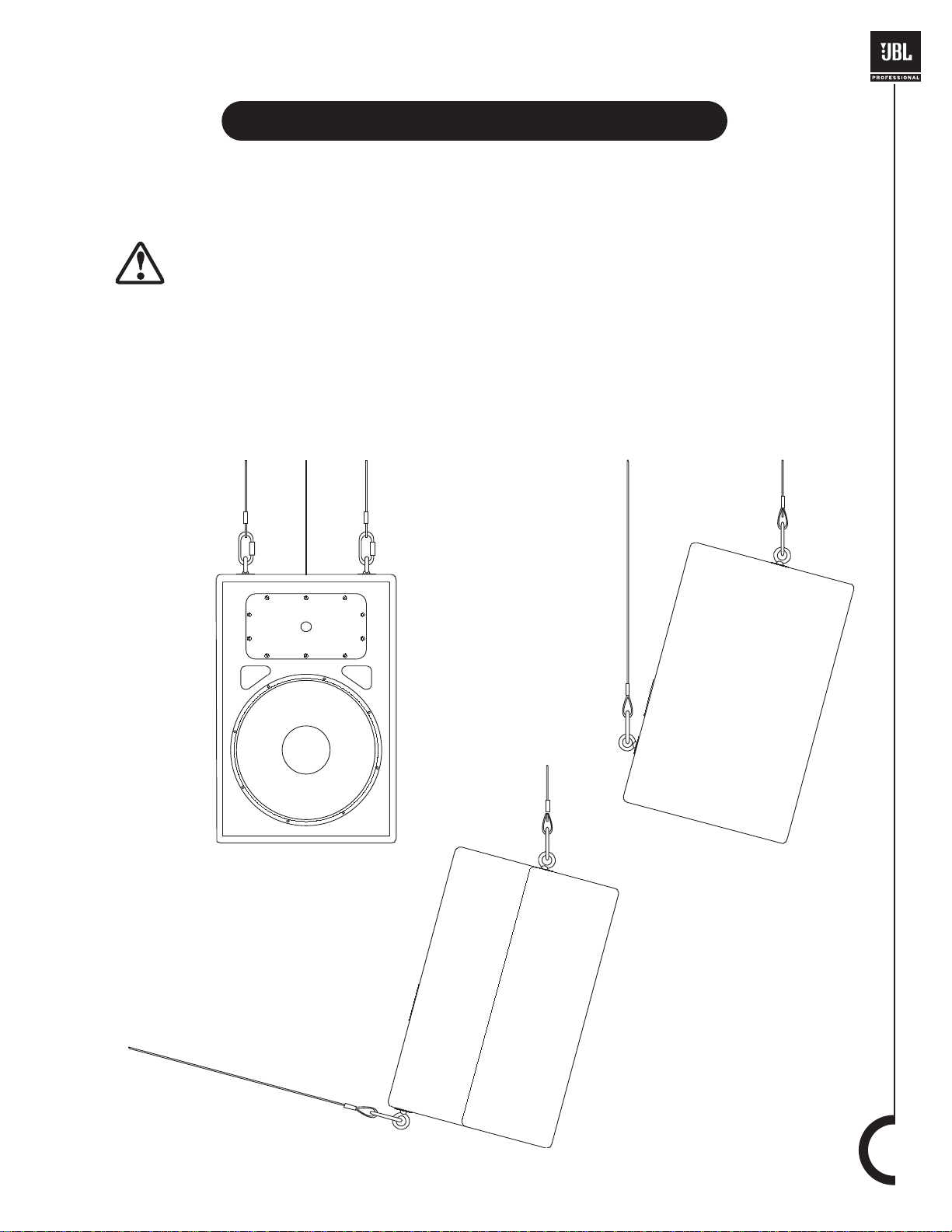
The JBL SoundFactor Install loudspeakers are supplied with built-in internal braces to be used with the
supplied forged shoulder ey ebolts or other approv ed f astener .The system is designed to f acilitate the suspension of the loudspeaker by a qualified person familiar with rigging hardware and industry practices.
IMPORTANT! You must ensure that ALL installation procedures specified in this manual
are carefully followed. Improper installation may result in damage, injury or death.
The working load limit (WLL) of any JBL SoundFactor Install loudspeaker is maintained as long as no
more than one loudspeaker is suspended by a minimum of two primary suspension points with no additional load placed on the loudspeaker enclosure.The JBL SoundFactor Install loudspeakers are intended for SINGLE-BOX SUSPENSION ONLY. DO NOT HANG A SECOND SPEAKER FROM A SOUNDFACTOR INSTALL SPEAKER.
Secondary
Load
Secondary
Load
Primary
Load
Primary
Load
Primary
Load
Secondary
Load
Primary
Load
SF15i
SF12Mi
Page 4
Proper Use of Forged Shoulder Eyebolt
General Hardware Information
4
Any hardware used in an overhead suspension application must be load rated for the intended use.
Generally, this type of hardware is available from rigging supply houses; industrial supply catalogs and
specialized rigging distributors.Local hardware stores do not usually stock these products.Hardware that
is intended for ov erhead suspension will comply with ASME B30.20 and will be manuf actured under product traceability controls. Compliant hardware will be referenced with a working load limit (WLL) and a
traceability code.
All SoundFactor Install loudspeakers include a rigging hardware kit (part# 229-00009-01) which includes
3 forged shoulder eyebolts and 3 washers.When installing these speakers, use hardware found in the kit
provided. For additional rigging components, consult with a professional rigging hardware supplier.
Sources for specialized rigging hardware may be found on page 11.
The JBL SoundFactor Install loudspeak ers are supplied with three f orged M10-1.5 x 35 mm shoulder ey ebolts with appropriate ratings and certified standards compliance, for use in overhead suspension applications.To install the eyebolts into the provided threaded holes on the loudspeaker, first remove the factory installed, flat head machine screw using a 6 mm hex key wrench. The M10-1.5 threaded internal
brace is accessible once the flat head machine screw is removed. Deposit thread lock adhesive, following the adhesive manuf acturer's instructions, onto the threaded tip of the eyebolt.Install the forged shoulder eyebolt as a replacement f or the machine screw, being careful not to cross-thread the fasteners.There
should be little resistance when installing any fastener. As a general rule for "soft surface" installations
such as a wooden surface, the suggested torque is achie ved by installing the fastener until snug and then
rotating the fastener an additional 180 degrees (1/2 turn).
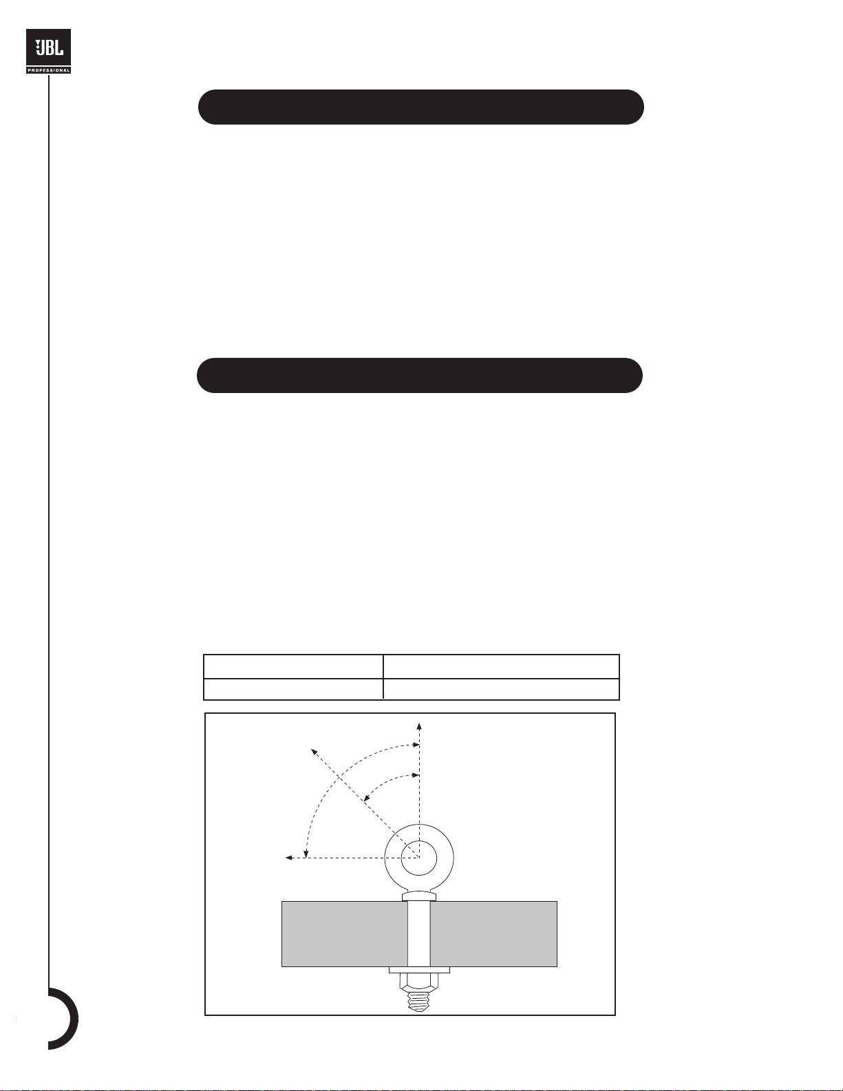
The load imposed on the eye of the eyebolt fastener must remain in the plane of the eye only.When anything other than a straight-line pull is used, the provided forged, shoulder eyebolt load rating must be
adjusted as follows:
Direction of Pull Adjusted Working Load
45 degrees 25% of rated working load
In-Line
45º
90º
Do Not
Load
Page 5

5
Proper Sling Termination
The slings described herein are "suspension slings" and are different from "lifting slings" as defined by
government regulatory bodies. Do NOT use hardware chain.The JBL SoundFactor Install loudspeakers
must be used in static suspension applications only. Wire rope suspension slings are suggested for all
installations requiring suspension of the JBL SoundFactor Install loudspeakers.The suggested wire rope
is identified as 1/8" 7 x 19 Galvanized Aircraft Cable (1/8- 7 x 19 GAC).The minimum working load limit
(WLL) of this type of wire rope is 400 lb / 181 kg when terminated properly.If sling lengths are pre-determined and the wire rope slings are fabricated at a rigging supplier, the suggested termination is identified
as "swaged Flemish eye terminations with heavy thimbles and certification tags." If sling lengths cannot
be predetermined and slings must be fabricated on site, the suggested termination is identified as either
a load rated "compression sleeve" or a forged "wire rope clip". Compression sleeves, such as the
Nicopress devices, require a specialized compression tool and associated check gauge.Wire rope clips
require an end-wrench, socket wrench, and/or adjustable wrench (spanner).The following table defines
the load rating adjustments associated with each termination type if the terminations are made according to manufacturer's instructions:
Termination T ype Adjusted Working Load
Swagged Flemish Eye 100% of wire rope rating
Load Rated Compression Sleeve 100% of wire rope rating
Forged Wire Rope Clip 80% of wire rope rating
Nicopress Oval Sleeve
Finished Eye Splice
Live
End
Dead
End
Saddle
U-Bolt
Page 6

Rigging Connections
6
Some installations require the use of a removable connection between the structure and the loudspeaker.Hardware commonly used for these applications includes:
Some installations require the adjustment of the length of one or more slings. Common hardware used
for these applications include:
Quick Link
Used in-line with only one wire
rope per end. Only use load rated
quick links, which will have the
WLL imprinted on the component.
Screw Pin Anchor Shackle
Used in-line or at an angle up to
45 degrees and can combine two
wire ropes into one. A mouse wire
(aka safety wire) must be used
after installation.
Turnbuckle
Used in-line with only one wire rope per end
and can be adjusted to length. A mouse wire
must be used after adjustment is complete.
Note: Use only turnbuckles with closed,
forged eyes.
Page 7

7
Attachment to Structures
A licensed Professional Engineer must approve the placement and method of attachment to the
structure prior to the installation of any overhead object. The following performance standards
should be provided to the Professional Engineer for design purposes; Uniform Building Code as applicable, Municipal Building Code as applicable, Seismic Code as applicable, and a minimum of a 5:1 design
factor throughout the suspension system.
The installation of the hardware and method of attachment must be carried out in the manner specified
by the Professional Engineer. Improper installation may result in damage, injury or death.
The following renderings represent some of the common methods of attaching to a structure.These renderings are intended as a reference only, and are not appropriate for many installation circumstances. In
the following illustrations, the structure component is shown in solid black while the attachment hardware
is drawn as an outline.
H-Beam Clamp (custom)
hardware as provided
Channel Beam Clamp (custom)
hardware as provided
Box Beam
Channel Beam
Beam Clamp
hardware as provided
H-Beam Clamp (custom)
hardware as provided
I-Beam
H-Beam
Page 8

Attachment to Structures
8
Angle Beam Clamp (custom)
hardware as provided
OSR Fitting
grade 8 or B7 fasteners
Wire Rope Sling (standard)
sling and SPA shackle
OSR Fitting
concrete anchors
Angle Beam
Wood Beam
Round Beam
Concrete Beam
Mounting Plate (standard/custom)
concrete anchors with epoxy
Brick Wall
Mounting Plate (standard/custom)
grade 8 or B7 fasteners
Metal Stud
Page 9

9
Specifications - SF12Mi
SF12Mi
System Type: 12" 2-way, stage monitor
Frequency Range (-10 dB):² 60 Hz - 16 kHz
Frequency Response (±3 dB):² 70 Hz - 12 kHz
Sensitivity (1w/1m): 98 dB SPL
Nominal Impedance: 8 Ω
Power Capacity:¹ 250 watts
Peak Power Capacity:¹ 1000 watts
Maximum SPL: 129 dB
Nominal Dispersion: 90° x 50°
Crossover Frequency: 1.8 kHz
Dimensions (H x W x D): 584.2 mm x 393.7 mm x 317.5 mm
(23 in x 15.5 in x 12.6 in)
Weight: 19.5 kg (43 lbs.)
Shipping Weight: 22.0 kg (48.5 lbs.)
High Frequency Driver: JBL 2412 1" exit compression driver mounted on Progressive Transition™ Waveguide
Low Frequency Driver: JBL M112-8
Input Connectors: Neutrik® Speakon® NL-4 (x1);1/4" TS phone jack (x1);parallel
Enclosure Construction: 19 mm (3/4 in) MDF (Medium Density Fiberboard);with glued and mechanically fastened joint
detail;covered in black carpet.
Grille: 18 gauge, powder-coated steel
Suspension: 3x M10 threaded suspension points
Suspension Kit: 3x 10 mm forged shoulder eyebolts with washers
Notes:
1."Power Capacity" and "Peak Power Capacity" ratings are based on the average and peak power handling capacity of product
samples subjected to a 100 hour power test of the system design using IEC filtered random noise with a crest factor of 6 dB.
2."Frequency Range" and "Frequency Response" are based on half-space response.
TIP
TIP
GRD
GRD
+
-
+
-
HPF
LPF
JBL PROFESSIONAL
Northridge, CA USA
Made in USA
MODEL SF12
IN / OUT
(PARALLEL JACKS)
8 OHMS
±1 FULL-RANGE
±2 N/C
1-1-1+
1+
Page 10

Specifications - SF15i
10
SF15i
System Type: 15" 2-way, sound-reinforcement speaker
Frequency Range (-10 dB):² 38 Hz - 16 kHz
Frequency Response (±3 dB):² 50 Hz - 12.5 kHz
Sensitivity (1w/1m): 98 dB SPL
Nominal Impedance: 8 Ω
Power Capacity:¹ 250 watts
Peak Power Capacity:¹ 1000 watts
Maximum SPL: 128 dB
Nominal Dispersion: 90° x 50°
Crossover Frequency: 1.6 kHz
Dimensions (H x W x D): 698.5 mm x 459.9 mm x 431.8 mm
(27.5 in x 18.11 in x 17 in)
Weight: 27.4 kg (60.5 lbs.)
Shipping Weight: 30.4 kg (67.0 lbs.)
High Frequency Driver: JBL 2412, 1" exit compression driver mounted on Progressive Transition™ Waveguide
Low Frequency Driver: JBL M115-8A
Input Connectors: Parallel Neutrik® Speakon® NL-4 (x1);1/4" TS phone jack (x1)
Enclosure Construction: 19 mm (3/4 in) MDF (Medium Density Fiberboard);with glued and mechanically fastened joint
detail;covered in black carpet.
Grille: 18 gauge, powder-coated steel
Suspension: 3x M10 threaded suspension points
Suspension Kit: 3x 10 mm forged shoulder eyebolts with washer
Notes:
1."Power Capacity" and "Peak Power Capacity" ratings are based on the average and peak power handling capacity of product samples subjected to a 100 hour power test of the system design using IEC filtered random noise with a crest factor of 6 dB.
2."Frequency Range" and "Frequency Response" are based on half-space response.
TIP
TIP
GRD
GRD
+
-
+
-
HPF
LPF
JBL PROFESSIONAL
Northridge, CA USA
Made in USA
MODEL SF15
IN / OUT
(PARALLEL JACKS)
8 OHMS
±1 FULL-RANGE
±2 N/C
1-1-1+
1+
Page 11

11
Product Dimensions
12.7 in
323 mm
60º
12 in
305 mm
8.4 in
213 mm
7.8 in
198 mm
3.9 in
99 mm
15.5 in
394 mm
2x O .45 in
11.4 mm
15.5 in
394 mm
22.7 in
577 mm
O .45 in
11.4 mm
1.8 in
45.7 mm
12.7 in
323 mm
8.4 in
213 mm
SF12Mi
27.2 in
691 mm
2x 2.4 in
60.9 mm
17 in
432 mm
18.5 in
470 mm
13.8 in
351 mm
3.8 in
96.5 mm
8.9 in
226 mm
5.4 in
137 mm
2x 82.5º
2x O .45 in
11.4 mm
8.0 in
203 mm
2x 1.75 in
44.5 mm
O .45 in
11.4 mm
3.5 in
88.9 mm
9.25 in
235 mm
17 in
432 mm
SF15i
Page 12

Mailing Address: Shipping Address:
JBL Professional JBL Professional
8500 Balboa Blvd. 8370 Balboa Blvd., Dock D
Northridge, CA 91329 Northridge, CA 91329
Customer Service: On the World Wide Web:
Monday through Friday www.jblpro.com
8:00am - 5:00pm
pacific coast time in the U.S.A. Product Registration:
(800) 8JBLPRO (800.852.5776) Register your product online at
www.jblproservice.com www.jblpro.com/registration
© Copyright 2003 JBL Professional
JBL Professional Contacts
Inspection, Maintenance and Liability
Suspension systems are comprised of mechanical devices and, as such, they require regular inspection and routine main
tenance to ensure that safety has not been compromised.The JBL SoundFactor Install loudspeakers and associated suspension components must be inspected f
or fatigue at least annually and immediately following exposure to impact,
mechanical shoc
k, fire, water or other hazard.The inspection must include a visual survey of all corners and load bearing
surfaces for signs of cracking, water damage, de-lamination, and any other condition that may decrease the strength of
the loudspeaker enclosure or associated suspension components. The forged shoulder eyebolts provided with the JBL
SoundFactor Install loudspeakers m ust be inspected for fatigue at least annually.The inspection must include a visual survey of the material for signs of corrosion, bending or any other condition that may decrease the strength of the fastener.
Additionally, the eyebolts must be checked for possible spin-out of the enclosure.For all other hardware and fittings, refer
to the hardware manufacturer's inspection and maintenance guidelines f or process. Should any signs of unsafe conditions
be observed, repair or replacement of the deteriorated component(s) must be completed before anyone other than someone performing the repair is allowed access to the vicinity of the unsafe condition.
Note:
The working load limit (WLL) of the JBL SoundFactor Install loudspeakers includes;a design factor equivalent to or
exceeding ASME B30.20, VBG70, VBG9a and the manufacturer's proprietary performance standard.
All implied warranties, including warranties of merchantability and fitness for particular pur pose, are limited in duration to
the length of the warranty. JBL's liability shall in no event exceed the cost of any defective product and shall not include
incidental or consequential damages of any kind, even if JBL has been advised of the possibility. Some states do not allow
limitations on how long certain warranties last and/or do not allow exclusion of incidental or consequential damages, so
the above limitations and exclusions may not apply to you.This warranty gives you specific legal rights, and you may also
have other rights which vary from state to state.
JBL is not responsible for the application of its products for any purpose or the misuse of this information for any purpose.
Furthermore, JBL is not responsible for the abuse of its products caused by av oiding compliance with inspection and maintenance procedures or any other abuse.
Allen Products ATM Fly-Ware
(562) 424-1100 (888) RIG-MORE / (310) 834-5914
1635 E. Burnett Street 2100 South Wilmington Avenue
Signal Hill, CA 90806 Carson, CA 90810
www.allenproducts.com www.atmflyware.com
M.A.N. Flying Systems McMaster Carr
20 Sidar Road Various locations through the United States.
Brook Road Industrial estate For a location near you, visit them online at
Rayleigh, Essex SS6 7XF www.mcmaster.com
www.manfly.co.uk
JBL Professional - Tech Note V1 No. 14
“Basic Principles For Suspending Loudspeakers”
www.jblpro.com/technote/tn_v1n14.pdf
Resources
 Loading...