

Page 1

SDP-RFD
AC-3
®
/RF
DEMODULATOR
(120V/230V)
INSTALLATION/
TECHNICAL
MANUAL
Page 2
2
Unpacking and Inspection
Save all packing materials in case you ever need to ship the unit.Thoroughly inspect the unit and
packing materials for signs of damage. Report any shipment damage to the carrier at once; report
equipment malfunction to your dealer.
Precautions
Save these instructions for later use.
Follow all instructions and warnings marked on the unit.
Always use with the correct line voltage.Refer to the manufacturer’ s oper ating instructions for po wer
requirements. Be advised that different operating voltages may require the use of a different line
cord and/or attachment plug.
Do not install the unit in an unventilated rack, or directly above heat-producing equipment such as
power amplifiers.Observe the maximum ambient operating temperature listed in the product specification.
Slots and openings on the case are provided for ventilation;to ensure reliable operation and prevent
it from overheating, these openings must not be blocked or covered.Never push objects of any kind
through any of the ventilation slots.Never spill a liquid of any kind on the unit.
This product is equipped with a 3-wire grounding type plug.This is a safety feature and should not
be defeated.
To prevent shock or fire hazard, do not expose the unit to rain or moisture, or operate it where it will
be exposed to water.
Do not attempt to operate the unit if it has been dropped, damaged, exposed to liquids, or if it
exhibits a distinct change in performance indicating the need for service.
This unit should only be opened by qualified service personnel. Removing covers will expose you to
hazardous voltages.
This triangle, which appears on your component, alerts you to the presence
of uninsulated, dangerous voltage inside the enclosure...voltage that may be
sufficient to constitute a risk of shock.
This triangle, which appears on your component, alerts you to important operating
and maintenance instructions in this accompanying literature.
Acknowledgements
The SDP Series is manufactured under license from Dolby Laboratories Licensing Corporation.
Additionally licensed under one or more of the following patents: U.S. numbers 3,632,886,
3,746,792 and 3,959,590; Canadian numbers 1,004,603 and 1,037,877. “Dolby” and the double-D
symbol are trademarks of Dolby Laboratories Licensing Corporation.
CAUTION
RISK OF ELECTRIC SHOCK
DO NOT OPEN
Page 3

3
1.
BASIC OPERATION
Congratulations on your purchase of
the Synthesis SDP-RFD AC-3®/RF
Demodulator. The SDP-RFD AC-3®/RF
Demodulator is designed to interface
between a laser disc player (with an
AC-3
®
/RF Demodulator output), and any
Dolby®Digital decoder which accepts a
standard AC-3®signal (like our SDP-2).
Because “AC-3
®
ready” laser disc players
use a separate Radio Frequency (RF)
modulated output to carry the Dolby
®
Digital information, special considerations must be made. While this type of
transmission works perfectly well, our
engineers were rightfully reluctant to
inject line-level RF directly into the
meticulously designed SDP-2. The solution is the SDP-RFD AC-3
®
/RF
Demodulator.
The SDP-RFD Demodulator keeps
potential RF interference away from the
sensitive preamp/processor stage while
providing highly useful improvements in
AC-3
®
signal quality. By placing the requisite demodulation circuitry in its own
enclosure with dedicated power supplies
and grounding, the potential to degrade
digital-to-analog conversion and analog
audio signals within the preamp/
processor is eliminated.
The SDP-RFD Demodulator incorporates fully automated “intelligent”
switching between S/PDIF and AC3
®
/RF inputs, meaning that any laser
disc will be decoded to its maximum
inherent quality. A low voltage “turn on
trigger” input and output are included
for interconnection to the Synthesis
SDP-2 and S-Series Amplifiers. The
stringently designed outboard power
supply ensures maximum signal purity.
We have designed this manual to provide a brief overview of the demodulator, as well as to provide the information
necessary for safe installation and operation. We trust that the time you invest in reviewing these brief instructions
will be rewarded by the best possible
performance and longevity of your
equipment.
1
INTRODUCTION TO THE SDP-RFD
AC-3®/RF DEMODULATOR
INTRODUCTION
Page 4
4
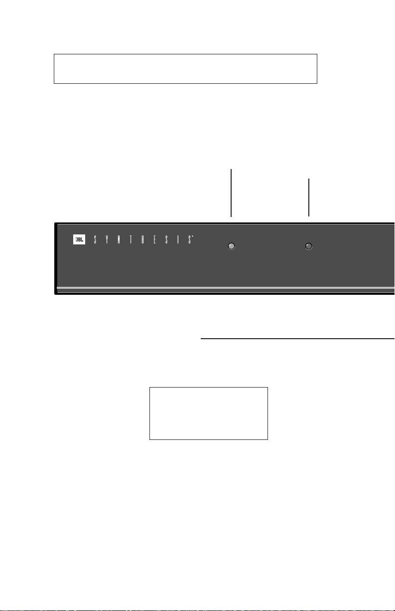
NOTE: When power is off, the SDP-RFD AC-3®/RF Demodulator
automatically outputs the COAXial digital input.
LOCK
This LED will light whenever
is present, the LED will rema
POWER
This LED will light whenever power to
the unit is supplied and enabled.
POWER
RF TIMING
LOCK
AC-3®/RF DEMODULATOR
RF TIMING
3-position switch which minimizes
signal errors, providing optimal
timing for specific brands of laser
disc players.
Recommended Settings
Advance
Panasonic, Runco
Retard Denon
Normal All others
Page 5

5
Front Panel
®
/RF signal. When no such signal
INPUT SELECT
2-position switch for selection of the type
of NON-AC-3
®
/RF digital output you are
using from your laser disc player.
ADVANCE
RETARD
NORMAL
OPTICAL
COAX
INPUT SELECT
Page 6

6
Connections between the SDP-RFD AC-3®/RF Demodulator and associated
equipment should be made with all units UNPLUGGED!
POWER
Connect the AC adapter here. Use only
the supplied Synthesis MSA AC adapter.
INPUT
Connect a 5-pin DIN cord (not supplied) from this input to the SDP-2
PWR CTL Output. This allows the
SDP-RFD to power on and off with
the SDP-2. If nothing is hooked up
here, the unit will turn on whenever the AC adapter is supplied
power. This set-up allows use of
a switched outlet or continuous
power. (As power consumption
and heat generation are both
minimal, this will not harm the
SDP-RFD.)
LOOP THRU
Allows the hook-up and power cycling of a
ditional components such as the Synthe
S Series of power amplifiers. Refer to
DIN configuration diagram below.
RF IN
Connect this input to the
output with a 75Ω coax
short as possible to min
1 = Ground
2 = Ground
3 = Power On (cons
when the DC-1 is On
4 = Unused
5 = Trigger (programma
POWER
9V~, 1A,
50-60Hz
JBL, INC.
NORTHRIDGE, CA 91329
MADE IN U.S.A.
SERIAL #
USE JBL
MSA AC ADAPTER
SDP-RFD AC-3®/RF
DEMODULATOR
PWR CTL
INPUT LOOP
THRU
PWR CTL
31
45
2
Page 7

7
Rear Panel
OUTPUT
Connect this S/PDIF output to SDP-2
digital input COAX1 with a 75Ω coaxial
cable.
S/PDIF INPUTS
Connect this input to the laser disc player’s NONAC-3®RF digital output using the appropriate 75Ω
coaxial cable.
Because you can switch between these inputs
from the front panel, you may use both; which
gives you an extra digital input.
the
®
/RF
RF IN S/PDIF INPUTS
THIS DEVICE COMPLIES WITH PART 15
OF THE FCC RULES.
OPERATION IS SUBJECT TO THE
FOLLOWING TWO CONDITIONS:
(1) THIS DEVICE MAY NOT CAUSE
HARMFUL INTERFERENCE, AND
(2) THIS DEVICE MUST ACCEPT ANY
INTERFERENCE RECEIVED,
INCLUDING INTERFERENCE THAT MAY
CAUSE UNDESIRED OPERATION.
AC-3
®
COAXS/PDIF OPTICAL
OUTPUT
Page 8

8
AUDIO
L
R
TAPE
TUNER CD AUX
L
R
L
R
TV V-DISC VCR2 VCR1
S-VIDEO
VIDEO
L
R
ZONE2 RECORD
OUTPUTS
VIDEO OUT
INPUTS
MONITOR RECORD
POWER
9V~, 1A,
50-60Hz
USE SYNTHESIS
MSA AC ADAPTER
PWR CTL
INPUT LOOP
THRU
PWR CTL
(to other components such as amplifiers)
ANALOG
AUDIO OUT
L
R
LASER DISC PLAYER
SDP-RFD AC-3
®
/RF
DEMODULATOR
SDP-2
75 ohm COA
(as short as po
COAX
Audio cable
Page 9

9
FRONT
CENTER
SUBWOOFER
REAR SIDE
L
R
ON
POWER
PWR CTL
IR IN
REMOTES
MAIN OUTPUTS
S/PDIF INPUTS
COAX
1
2
OPTICAL
1
2
RF IN S/PDIF INPUTS
AC-3
®
COAXS/PDIF OPTICAL
OUTPUT
AC-3®/RF OUTPUT
DIGITAL OUTPUT
COAX
OPTICAL
(TOSLINK)
OR
75 ohm COAX cable
COAX 1 (digital input)
Default input for V-DISC
5-pin DIN cable (not included)
75 ohm
COAX cable
Optical cable
(Use one or the other.
Most players have only one.)
Page 10

10
Setup
The SDP-RFD AC-3®/RF Demodulator
chassis is barely four inches deep to
allow it to be positioned adjacent to an
AC-3
®
-capable player’s RF output. This
minimizes the required RF-signal cable
length to reduce any RF interference. As
the unit uses automated switching, and
draws very little power, you can literally
set it and forget it.
To set up the SDP-RFD:
• Connect a 75Ω coaxial cable
between the SDP-RFD rear panel
RF (AC-3
®
) input and the laser disc
player's RF/AC-3®output. Keep
this cable as short as possible to
minimize RF interference.
• Connect a 75Ω coaxial (or optical)
cable between the SDP-RFD
S/PDIF input and the laser disc
player’s digital output.
• Connect a 75Ω coaxial cable
between the SDP-RFD S/PDIF output and the SDP-2 COAX 1 digital
input.
• Recommended: Connect a 5-pin
DIN cord (not supplied) between
the SDP-RFD PWR CTL input and
the SDP-2 PWR CTL output. This
allows the SDP-RFD to power on
and off with the SDP-2. If this connection is not made, the SDP-RFD
will turn on whenever its AC
adapter is supplied power.
• Optional: Connect any additional
components which allow remote
turn on (such as Synthesis’
S Series of power amplifiers)
to the SDP-RFD rear panel PWR
CTL (LOOP THRU) connector.
• Connect the AC adapter provided
to the POWER jack.
Once the SDP-RFD is properly connected, set the front panel INPUT
SELECT switch for the appropriate type
of NON-AC-3
®
/RF digital output you are
using on your laser disc player. (Most
laser disc players have only one.) Set
the RF TIMING switch according to the
chart provided on page 2. Once you
have completed the connections and
setting of the front panel switches, all
functions are performed automatically.
LEDs on the front panel are provided to
identify the operational state.
Maintenance
The SDP-RFD requires no maintenance.
However, it is good electrical practice to
clean all connectors once a year. Clean
the exterior surfaces of the unit with a
soft, lint-free cloth, dampened with
warm water.
Page 11

11
Inputs
2: 1AC-3®/RF via COAX; 2 Digital (1 COAX; 1 Optical)
Outputs
One (1) Digital via COAX
RF Timing
3-position toggle switch, decoder pulse settings
Controls and Indicators
LEDs indicate operational status
Toggle switches for: LD
RF Timing: Advance, Retard, Normal
Input Select: Optical, COAX
Connectors
Inputs: 4: 2 RCA (COAX); 1 TOSLINK (Optical); 1 5-pin DIN (PWR CTL)
Outputs: 2: 1 RCA (COAX); 1 5-pin DIN (PWR CTL Thru)
Power connector: 2.5mm, 9VAC, 1A
General
Dimensions: 17.0"X x 1.75"H x 4"D
Weight: 2.4 lbs net; 4.4 lbs shipping
Power Requirements: 120VAC, 60Hz or 230VAC, 50Hz.
Use JBL MSA AC Power Adapter.
All specifications subject to change without notice.
2.
SPECIFICATIONS
2
SPECIFICATIONS
Page 12

Declaration of Conformity
JBL Synthesis System Owner's Manual
©1997 Harman Consumer Group
JBL and Synthesis are registered trademarks of JBL Incorporated.
All Rights Reserved
Manual Designed by Harman Consumer Group
Design & Production Center • Woodbury, New York
JBL Consumer Products, Inc.
80 Crossways Park West, Woodbury, NY 11797
(516) 496-3400
8500 Balboa Boulevard, Northridge, CA 91329
www.jbl.com
Part No. 1111-SDP/RFD
Printed in USA on recycled paper
A Harman International Company
We, JBL Europe A/S
Kongevejen 194B
DK-3460 Birkerød
DENMARK
declare in own responsibility, that the product described
in this owner’s manual is in compliance with technical
standards:
EN 55 013/6.1990
EN 55 020/6.1988
EN 55 022/6.1993
EN 60 065/1994
EN 60 555-2-3/1987/88
Steen Michaelsen
JBL Europe A/S
Birkerød. DENMARK. 2/97
 Loading...