

Page 1

Simply Cinema Surround Cinema
Models: SCS135
SCS135SI
SCS136SI
SCS145.5S
Home Theater Speaker Systems
SERVICE MANUAL
JBL Incorporated
250 Crossways Park Dr.
Woodbury, New York 11797 REV 6 12/2004
Page 2

SCS135/SCS135SI/SCS136SI/SCS145.5S
TABLE OF CONTENTS
BASIC SYSTEM SPECIFICATIONS……………….………………..2
DETAILED SPECIFICATIONS ………………………………………3
CONNECTIONS . . . . . . . . . . . .. . …………. . . . . . . . . . . . . . . . . .4
OPERATION . . . . . . . . . . . .. . . . . . . ……………. . . . . . . . . . . . . .6
TROUBLESHOOTING . . . . . . . . .. . . . . . . ….. . . . . . . . . . . . . . . .7
MECHANICAL/PACKAGING PARTS LIST…………………………8
DETAILED EXPLODED VIEW.......................................................9
TEST SET UP AND PROCEDURE . . . .. . . . . . . . . . . . . . . . . . . .10
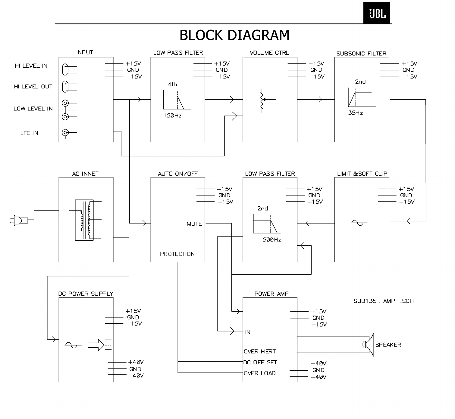
BLOCK DIAGRAM. . . . . . . . .. . . . . . . ……….. . . . . . . . . .. . . . . .11
ELECTRICAL PARTS LIST . . . . . .. . . . . . . . . . . . . . . . . . . . . . . .12
INTEGRATED CIRCUIT DIAGRAMS . . . . . . . . . . . . . . . . . . . . . .15
PRINTED CIRCUIT BOARDS . . . . . .. . . . . . . . . . . . . . . . . ... . . .16
SCHEMATICS . . . . . . . . . . . . . . . . .. . . . . . . . . . . . . . . . . ….. . . .20
WIRING DIAGRAM. . . . . . . . .. . . . . . . ……….. . . . . . . . . .. . . . . 22
PACKAGING . . . . . ……………………….……………….. . . . . . . .23
1
Page 3

SCS135/SCS135SI/SCS136SI/SCS145.5S
2
Specifications
SCS135/SCS135SI/SCS136SI/SCS145.5S SYSTEMS
Frequency Response 35Hz - 20kHz (-6dB)
Satellites
Recommended Power 10 - 100 watts
Impedance 8 ohms nominal
Sensitivity 86dB @ 1 watt/1 meter
Tweeter One 1/2" (13mm) titanium-laminate dome, video-shielded
Midrange One 3" (76mm) driver, video-shielded
Dimensions (H x W x D) 4-3/8" x 3-3/16" x 3-3/4" (111mm x 81mm x 95mm)
Weight 1.1lb/0.5kg
Center Channel
Recommended Power 10 - 50 watts
Impedance 8 ohms nominal
Sensitivity 86dB @ 1 watt/1 meter
Tweeter One 1/2" (13mm) titanium-laminate dome, video-shielded
Midrange Dual 3" (76mm) drivers, video-shielded
Dimensions (H x W x D) 3-1/4" x 7-5/8" x 3-3/4" (83mm x 194mm x 95mm)
Weight 1.89 lb/0.86kg
Subwoofer
Power: 100 watts RMS
8" (203mm) woofer, bass-reflex enclosure
Dimensions (H x W x D) 15" x 13" x 14" (381mm x 330mm x 356mm)
Weight 30 lb/13.6kg
Refinements may be made on occasion to existing products without notice, but will always meet or exceed original
specifications unless otherwise stated.
Simply Cinema is a registered trademark of JBL, Incorporated.
Page 4

SCS135/SCS135SI/SCS136SI/SCS145.5S
3
SUB135/136/145.5 Amplifier 100W Powered Sub/ Plate Amp
LINE VOLTAGE Yes/No Hi/Lo Line Unit Notes
Parameter Specification Unit QA Test Limits Conditions Notes
Amp Section
Type (Class AB, D, other) AB AB
Load Impedance (speaker) 4 Ohms
Rated Output Power 100 Watts
THD@ Rated Power 0.08 %
THD @ 1 Watt 0.1 %
DC Offset 10 mV-DC
Damping factor >100 DF
Input Sensitivit
Signal to Noise
SNR-A-Weighted 100 dBA
SNR-unweighted 80 dBr
SNR @ 1W-unweighted 60 dBr
Residual Noise Floor 1.5 mVrms
US 120vac/60Hz Yes 108-132 Vrms
Asia 100vac/50Hz Yes 90-110 Vrms
y
Input Frequency 50 Hz
Line Input (L&R) 250 mVrms
LFE Input 135 mVrms
Speaker/Hi Level Input 2.5 Vrms
n/a External Sink required for Class AB
n/a Nominal Z-curve required
95 1 input driven
0.3 22k filter
0.5 22k filter
20 @ Speaker Outputs
50
50 Nominal Freq. 1 input driven
±2dB To Rated Power 1 input driven
±2dB To Rated Power LFE input driven only
±2dB To Rated Power (-20 dB below Line In)...1 input driven
90 rel. to rated power A-Weighting filter
75 rel. to rated power 22k filter
55 rel. to 1W Output 22k filter
2.5
Normal Operation
Normal Operation
Volume @max, using RMS reading
DMM/VOM (or A/P)
Measured at speaker terminals, Output
power 90 Watts THD 0.1 %
Residual Noise Floor 1
Input Impedance
Line input L&R , LFE >15 K ohms
Speaker/Hi Level Input 4.7 K ohms
Filters
Low Pass (fixed or variable) fixed --
Subsonic filter (HPF) Hz
r (yes/no) YES --
Limite
Features
LFE Input YES
Volume pot Taper (lin/log) log -ATO YES
Input Configuration
Line In (L,R) L ,R -Line level in LFE LFE
Spkr/Hi Level In
Signal Sensing (ATO
Auto-Turn-On (yes/no) YES -ATO Input Frequency 50 Hz
ATO Level 2 mV
ATO Turn-on time 5 ms
Auto Mute/ Turn-OFF Time 15 minutes
Power on Delay tim
Transients/Pops
ATO Transient 5 mV-peak
Turn-on Transient 50 mV-peak
Turn-off Transient 50 mV-peak
Efficienc
Stand-by Input Power 13 Watts
Power Cons.@rated power 185 Watts
Protection
Short Circuit Protection YES -Thermal Protection 65 deg. C -DC Offset Protection YES --
Slope & Q dB/Octave
Slope & Q dB/Octave
(L,R)
)
e 3 sec.
y
mVrms(max)
L,R --
2
n/a Nominal
n/a Nominal
±2dB
n/a
±2dB
n/a
n/a
functional BW Limited to 500 Hz
functional
functional
functional RCA inputs: L , R Summed to Mono
functional
functional L R Summed to Mono
functional
functional
functional
functional AC on, signal applied
functional T before muting, after signal is removed Auto turn of time (T) must be 10 > T <15
functional AC Power Applied
10 @ Speaker Outputs
100 @ Speaker Outputs AC Line cycled from OFF to ON
100 @ Speaker Outputs AC Line cycled from ON to OFF
15 @ nom. line voltage Maximum allowable input power.
195 @ nom. line voltage
functional Direct short at output
functional @1/8 max unclipped Power rise
functional DC present at Speaker Out leads Relay or crowbar (for driver/fire protection)
Volume @max, w/ A/P Swept Bandpass
Measurement (Line freq.+ harmonics)
@p
driven
100 Watts @ 4 Ohms nominal line voltage
Line Fuse Rating 2.5 Amps
2.5 Type-T or Slo Blo External fuse with UL/SEMKO rated holder
Page 5

Right Front
Right Surround
Left Front
Left Surround
Center
+ – + –
+ –
+ –
+ –
+ –
+ –
Left Front Center
+ –
Left Surround
Right Front
+ –
Right Surround
+ –
Subwoofer
Receiver
HIGH LEVEL
+ – – +
L R
OUT
IN
SCS135/SCS135SI/SCS136SI/SCS145.5S
4
Connections
SPEAKER CONNECTIONS
Connection Tips
*
Pro Logic*(Non-Digital) – Speaker Level
Dolby
Use this installation method
for Dolby Pro Logic applications (not Dolby Digital,
®
or other digital process-
DTS
ing), where the
receiver/processor does not
have a subwoofer output, or
a volume-controlled preamp
(line-) level output:
Connect your receiver or
amplifier’s front left and right
speaker terminals to the left
and right terminals on the
subwoofer that are marked
“High Level In.” Connect the
left and right terminals on the
subwoofer that are marked
“High Level Out” to the corresponding terminals on the
back of your front left and
right speakers.
Connect your receiver or
amplifier’s center, left and
right surround-speaker terminals to the corre-sponding
terminals on the back of your
center, left and right surround
speakers.
Separate and strip the
ends of the speaker wire
as shown. Speakers and
electronics terminals have
corresponding (+) and (–)
terminals. Most manu-facturers of speakers and electronics, including JBL, use
red to denote the (+) terminal
and black for the
(–) terminal.
The (+) lead of the speaker
wire is noted with a stripe. It
is important to connect both
speakers identically: (+) on
the speaker to (+) on the
amplifier and (–) on the
speaker to (–) on the amplifier. Wiring “out of phase”
results in thin sound, weak
bass and a poor
stereo image.
With the advent of multichannel surround-sound systems, connecting
all of the speakers in your
system with the correct
polarity remains equally
important in order to preserve the proper ambience
and directionality of the program material.
Page 6

LINE LEVEL IN
LFE INPUT
LFE OUT
L
R
SUBWOOFERRECEIVER
+ –
+ –
+ –
+ –
+ –
+ –
+ –
+ –+ –
+ –
Receiver
Subwoofer
Out
Left
Front
Left
Rear
Right
Front
Right
Rear
Subwoofer
R L
R
L
Center
LineLevel
In
Right Surround
Right Front
Left Surround
Left Front
Center
SCS135/SCS135SI/SCS136SI/SCS145.5S
5
Connections
Dolby Pro Logic (Non-Digital) – Line Level
Use this installation method
for Dolby Pro Logic applications (not Dolby Digital, DTS
or other digital processing),
where the receiver/processor
is equipped with a subwoofer
output, or a volume-controlled
preamp (line-) level output:
Use RCA-type patch cords
to connect the line-level subwoofer outputs on your
receiver or amplifier to the
line-level inputs on the subwoofer. IMPORTANT: Do not
use the LFE input on the subwoofer with Dolby Pro Logic
processors. Note: If your
receiver or amplifier only has
one subwoofer output jack,
then you will need to use a Yconnector (not included).
Plug the male end of the Yconnector into your receiver
or amplifier’s subwoofer output jack, and connect each of
the two female ends to separate RCA-type patch cords.
Finally, plug the RCA-type
patch cords into the line-level
inputs on the subwoofer.
Connect each speaker to
the corresponding speaker
terminals on your receiver
or amplifier.
Dolby Digital or DTS (or Other Digital Surround Mode) Connection
Use this installation method
for Dolby Digital, DTS or other
digital surround processors:
Use the line-level input jack
marked “LFE” for the LowFrequency Effects channel.
Connect this jack to the LFE
output or subwoofer output
on your receiver or amplifier.
Connect each speaker to the
corresponding speaker termi-
nals on your receiver
or amplifier.
Make sure that you have configured your surround-sound
processor for “Subwoofer
On.” The front left, front right,
center and rear speakers
should all be set to “Small.”
Page 7

MIN MAX
Subwoofer
Level
MIN MAX
Subwoofer
Level
VOLUME
Volume may be adjusted
using the Subwoofer Level
control
£ as shown.
SCS135/SCS135SI/SCS136SI/SCS145.5S
6
OPERATION
Move the Master Power
switch (marked “Power” ¡)
to the “•” (On) position to use
the subwoofer. The
subwoofer will automatically
turn on or go into standby
(sleep) mode when left in the
auto mode (“Auto/On” switch
HIGH LEVEL
+ – – +
L R
OUT
IN
IMPORTANT: CONNECT STRIPED WIRE TO RED ( ) SPEAKER TERMINAL.
CAUTION
RISK OF ELECTRIC SHOCK
DO NOT OPEN
LINE LEVEL IN
LFE
+
™ in the “Auto” position).
When your receiver or amplifier is off, or is not sending
program material to the subwoofer, the subwoofer will be
in standby mode (LED will be
SUBWOOFER
LEVEL
MIN MAX
AC 120V~60Hz
woofer
it will
red). When the sub
senses an audio signal,
L
AUTO ON
R
GREEN: ON
RED: STANDBY
POWER
automatically turn on (LED will
be green). If the subwoofer
does not sense a signal after
approximately twenty minutes,
it will automatically go back
into standby mode.
When the “Auto/On” switch
™ is switched to the “On”
position, the subwoofer will
remain on, whether or not
™
program material is playing.
If you will be away from home
£
for an extended period of time,
or if the subwoofer will not
be used, switch the Master
Power switch ¡ to the Off
position.
¡
Page 8

SCS135/SCS135SI/SCS136SI/SCS145.5S
7
TROUBLESHOOTING
If there is no sound from any
of the speakers:
• Check that receiver/amplifier
is on and a source is playing.
• Check that the powered
subwoofer is plugged in, its
Power switch ¡ is switched
on to the “•” position, and the
“Auto/On” switch ™ is either
in the “On” or “Auto” position.
• Check all wires and connections between receiver/
amplifier and speakers. Make
sure all wires are connected.
Make sure none of the speaker wires are frayed,
cut or punctured.
• Review proper operation of
your receiver/amplifier.
If there is no sound coming
from one speaker:
• Check the “Balance” control
on your receiver/amplifier.
• Check all wires and connections between receiver/
amplifier and speakers. Make
sure all wires are connected.
Make sure none of the
speaker wires are frayed,
cut or punctured.
• In Dolby Digital or DTS
modes, make sure that the
receiver/processor is configured so that the speaker in
question is enabled.
If there is no sound from the
center speaker:
• Check all wires and connections between receiver/amplifier and speaker. Make sure
all wires are connected. Make
sure none of the speaker
wires are frayed, cut or punctured.
• If your receiver/processor is
set in Dolby Pro Logic mode,
make sure the center speaker
is not in phantom mode.
• If your receiver/processor
is set in Dolby Digital or DTS
mode, make sure the receiver/processor is con-figured so
that the center speaker is
enabled.
If the system plays at low volumes but shuts off as volume
is increased:
• Check all wires and connections between receiver/
amplifier and speakers. Make
sure all wires are connected.
Make sure none of the
speaker wires are frayed, cut
or punctured.
• If more than one pair of main
speakers is being used, check
the minimum impedance
requirements of your receiver/amplifier.
If there is low (or no) bass
output:
• Make sure the connections
to the left and right “Speaker
Inputs” have the correct
polarity (+ and –).
• Make sure the subwoofer
is plugged into an active electrical outlet.
• Make sure the powered subwoofer is plugged in
and is either in the “On” or
“Auto” position.
• In Dolby Digital or DTS
modes, make sure your
receiver/processor is configured so that the sub-woofer
and LFE output
are enabled.
If there is no sound from
the surround speakers:
• Check all wires and connections between receiver/
amplifier and speakers. Make
sure all wires are connected.
Make sure none of the
speaker wires are frayed, cut
or punctured.
• Review proper operation of
your receiver/amplifier and its
surround-sound features.
• Make sure the movie or TV
show you are watching is
recorded in a surround-sound
mode. If it is not, check to see
if your receiver/ amplifier has
other surround modes you
may use.
• In Dolby Digital or DTS
modes, make sure your
receiver/processor is configured so that the surround
speakers are enabled.
• Review the operation of your
DVD player and the jacket of
your DVD to make sure that
the DVD features the desired
Dolby Digital or DTS mode,
and that you have properly
selected that mode using both
the DVD player’s menu and the
DVD disc’s menu.
Page 9

SCS135/SCS135SI/SCS136SI/SCS145.5S
Description
SUBWOOFER
Amplifier Ass’y Not for Sale Not for Sale Not for Sale Not for Sale
8” Woofer
DCR = 3.4 ohms ±10%
Rubber Foot Pad wi5448 wi5448 321-ABS-00009 321-RUB-00009
Foot wi5447 wi5447 321-ABS-00008 321-ABS-00008-0LA
SATELLITES
Complete SCS135/SAT-01 SCS135SI/SAT-1 SCS136SI/SAT-1 SCS145.5S SAT-1
Woofer 22PF48SA-DW01-01 22PF48JZA-DW02 22PF48JZA-DW02 22PF48JZA-DW02
X-over Network xr5076 xr5076-1 013-AA00-00238 Not for Sale
Grille G225000 xc225005 244-020-00074 244-020-05041-0VA
Enclosure xd225000-d 247-020-00107
Front baffle Xc225006-d 243-020-00171
Front foot WI5213 WI5213 WI5213 320-RUB-00053-0LA
Rear foot WI0782 WI0782 WI0782 320-RUB-00025-0LA
Wall bracket WI0408 WI0408 372-000-00042 372-000-00042
Support mural WI0409 WI0409 325-FE-00163 325-FE-00163
CENTER CHANNEL
Complete SCS135/CENTER-01 SCS135SI/CENTER-1 SCS136SI/CENTER-1 SCS145.5S CEN-1
Woofer 22PF48SA-DW01-01 22PF48JZA-HW01 22PF48JZA-HW02 22PF48JZA-HW02
X-over Network xr5151 xr5151-1 013-AA00-00668 Not for Sale
Grille G225001 xc225004 244-020-00073 244-020-05042-0VA
Enclosure xd225001-d 247-020-00111
Front baffle xc225007-d 242-020-00378
Rubber Foot 320-RUB-00053-0LA
SCS135 SCS135SI SCS136SI SCS145.5S
20MF10DAG-DW03 20MF10DAG-DW03 20MF10DAG-DW03 20MF10DAG-DW02
Mechanical/Packaging Parts List
PACKAGING
Owner's manual ai5073 ai5193 406-000-00889 406-000-05100
Warranty card at5160 at5160 405-000-00258 405-000-00258
Survey card ai0193 ai0193
Styrofoam (Subwoofer) wp5110 wp5110 431-000-00729 431-000-00729
Styrofoam (Satellites) wp5101 wp5101 431-000-00938 431-000-00420
Outer carton wg5164 wg5362 402-000-01767 402-000-05179
Wire set (Sub in/out) SAL063-1 SAL063-1 370-000-00069 370-000-00069
Wire set (sats & center) SAL5019 SAL5019 370-000-00087 370-000-00087
Wire set (surround) SAL5009 SAL5009 370-000-00081 370-000-00081
OPTIONAL: Floor Stands for 135SAT & 136SAT satellites - FS300
Floor Stands for 145.5SAT satellites – FS1000
8
Page 10

SCS135/SCS135SI/SCS136SI/SCS145.5S
9
8
EXPLODED VIEWS
1
29
2
3
4
3
4
5
6
7
3
4
43
42
40
41
43
42
39
k
l
c
d
n
e
f
39
38
a
b
m
h
g
17
20
38
18
17
16
15
14
13
16
21
14
11
22
26
19
20
22
44
26
23
24
11
10
o
p
q
r
a
k
b
o
p
q
c
l
r
24
d
e
n
f
35
j
35
i
17
h
m
22
36
g
9
35
36
37
36
25
28
27
36
35
34
31
32
33
12
29
30
17
REF.No.
1
2
3
4
5
66
7
8
9
10
11
12
13
14
15
PARTS No.
N/A
N/A
See parts list
06-T43005
PA06001
See parts list
06-T4205012
730A125
N/A
723D125
1010SUB135
700KB800
653HS135-S
1933M2520
192021TIP35C
EM PTY C ABIN ET ASSEMBL Y
DESCRIPTION
PORT TUBE
RUBBER FOOT
Ø
WOOD SCREW
SPEA KER EVA CUSHIOH 600x7x1 t
JB L 8" 35M M 4
WOOD SCREW 4x 20mm
SOUND-ABSORBENT
REAR PANEL 215x270x2.5t
EVA CUSH IO N 170x 5 x 1 t
PRE. AMP./POWER AMP. P.C. BOARD
SUB. LEVEL KNOB
HEAT SINK 65x32x31 (ALUMINIUM)
MICA
TRANSISTOR TIP35C
4x30
Ω
SUBWOOFER
Q'TY
1
1
4
4
1
1
8
1
1
1
1
1
1
2
1
REF.No.
16
17
18
19
20
21
22
23
24
25
26
27
28
29
30
PARTS No.
712A130
06-M30814
650LB800
06-M31403
650SUB240
192022TIP36C
06-M30809
150E8604107
725A125
06-M41605
06-N4HW01
180PBR12C11S
1302G472MD00
707AC800
152U602015
SHOULDER WASH ER (SW 06002)
DESCRIPTION
SCREW M3x8 TYPE TT
BRA CKE T 14 . 2x8.0x5.2 t=1.6mm
SCREW M3 x1 4xP0 .5 m m
PCB RRACKET L TYPE T=1.6mm A.P.C.C
TRANSISTOR TIP35C
SCREW M3x8xP0.5 TYPE C
TRANSFO R ME R EI -8 6 60 Hz 120V TT086990 65 8 0
RUBBER CU SH IOH 25x2 1x4t
SCR EW M4 x16 TYPE TYPE C
TOOTH LOCK WAS HER FOR M4 NUTS
POWER PUSH SW . BR12C11S
%
20
CER AMICS CAP. 4700P 400V
CORD BUSHINHS
AC CORD SVT FT-2 6FT
±
Q'TY
2
2
1
1
2
1
4
1
4
4
4
1
1
2
1
REF.No.
31
32
33
34
35
36
37
38
39
40
41
42
43
44
PARTS No.
653HS 135-1
154U25006T0
155520020
16210082007
06-T41208
06-T4205012
06-T31004
723A125-1
723B125-1
700RC800A
16210302001
723A125
723B125
06-T30804
HEAT SINK 117.5x60x25
DESCRIPTION
FUSE 2.5A 250V 20mm
FUSE HOLDER R3-11
WIRE RED 18AWG 80mm
WOOD SCREW 4x 12mm
WOOD SCREW t4x20mm
SCREW M3 x10m m
EVA CUSH IO H 213x 15x1 . 0 t
EVA CUSH IO H 238x 15x1 . 0 t
REAR CABINE T 26 8x 213x102 A.B.S UL
SPEA KER WIRE UL1015 300m m
EVA CUSH IO H 213x 15x2 . 0 t
EVA CUSH IO H 238x 15x2 . 0 t
SCR EW 3 x8 mm PAN TYPE C
Q'TY
1
1
1
1
4
10
4
2
2
1
1
2
2
2
00335
Page 11

SCS135/SCS135SI/SCS136SI/SCS145.5S
10
SIGNAL
GENERATOR
AMPLIFIER
Test Set Up and Procedure
Equipment needed:
• Function/signal generator/sweep generator
• Integrated Amplifier
• Multimeter
• Speaker cables
AC VOLT
METER (10V)
SUBWOOFER
UNDER TEST
SPEAKER
OUTPUT
FROM
AMPLIFIER
CAUTION
RISK OF ELECTRIC SHOCK
DO NOT OPEN
I
AC 120V-60Hz
200 Watts
00365
General Unit Function (UUT = Unit Under Test)
1) From the signal generator, connect one line level (RCA) cable to the Subwoofer Line Level Input jacks L/R
on the UUT. Use a Y-cable from a mono source if necessary to connect to both inputs. Do not connect to
the single SUB input.
2) On the front of the unit, turn the LEVEL control full counterclockwise.
3) Turn on generator, adjust to 100mV, 50 Hz.
4) Plug in UUT; turn the power switch ON. LED should be Red. Turn LEVEL control full clockwise (MAX)
5) LED should now be Green; immediate bass response should be heard and felt from port tube opening.
6) Turn off generator, turn VOLUME control fully counterclockwise, disconnect RCA cable.
7) Connect one pair of speaker cables to Speaker Level input terminal (IN) on UUT. Cables should be connected to an integrated amplifier fed by the signal generator.
8) Turn on generator and adjust so that speaker level input at the amplifier is 2.0V, 50 Hz. Turn LEVEL con-
trol full clockwise.
9) Green LED should light, immediate bass response should be heard and felt from the port tube opening.
Sweep Function
1) Follow steps 7-9 above, using a sweep generator as a signal source.
2) Sweep generator from 20Hz to 300Hz. Listen to the cabinet and drivers for any rattles, clicks, buzzes or
any other noises. If any unusual noises are heard, remove woofers and test.
Driver Function
1) Remove woofer from cabinet; detach + and - wire clips.
2) Check DC resistance of woofer; it should be 3.4 ohms ±10%
3) Connect a pair of speaker cables to driver terminals. Cables should be connected to an integrated amplifier fed by a signal generator. Turn on generator and adjust so that speaker level output is 5.0V.
4) Sweep generator from 20Hz to 1kHz. Listen to driver for any rubbing, buzzing, or other unusual noises.
11
Page 12
SCS135/SCS135SI/SCS136SI/SCS145.5S
11
Page 13

SCS135/SCS135SI/SCS136SI/SCS145.5S
12
Electrical Parts List
Part Description Qty Reference
No. Designator
SEMICONDUCTORS
197131n4148 DIODE 1N4148 26mm TAP 9 D101, 103, 105, 108, 201, 202,
206, 207, 208
19915000335 ZENER 3.3V 1/2W 26mm TAP 2 D102, 205
19915000625 ZENER 6.2V 1/2W 26mm TAP 2 D106, 107
19915001605 ZENER 16V 1/2W 26mm TAP 1 D109
19510204hgw LED 204HGW 1 D209
19700kbl405 BD 4A 500V KBL405 BRIDGE 1 D110
197101n4002 DIODE 1N4002 1 D104
197101n4148 DIODE 1N4148 2 D301, 302
192027c1815gr TR 2SC1815GR TAP 8 Q102, 111, 112, 113, 118, 206,
207, 208
192028a1015gr TR 2SA1015GR TAP PNP 2 Q114, 116
1921672n5551 TR 2N5551 TAP NPN 2 Q103, 109
1921682n5401 TR 2N5401 AI-PNP 350V 500mA TO-92 2 Q104, 110
192021c1815gr TR 2SC1815GR NPN 4 Q101, 115, 301, 302
192011d669a TR 2SD669A NPN 1 Q106
192021tip35c TR TIP35C NPN 1 Q107
192012b649a TR 2SB649A PNP 1 Q105
192022tip36c TR TIP36C PNP 1 Q108
192201d882y TR KSD882Y PNP 1 Q117
192202b772y TR KSB772Y PNP 1 Q119
19006m4558d IC OPA 4558D QUAD OP-AMP 2 U101, 203
19016tl074cn IC TL074CN ST QUAD OP-AMP 3 U201, 202, 301
RESISTORS
11014122j26 RES 1.2K 1/4W 5% CF 26mm TAP 1 R265
11014472j26 RES 4.7K 1/4W 5% CF 26mm TAP 4 R147,150,201,202
11014681j26 RES 680 1/4W 5% CF 26mm TAP 2 R148,151
11016101j26 RES 100 1/6W 5% CF 26mm TAP 4 R120,213,214,215
11016102j26 RES 1K 1/6W 5% CF 26mm TAP 2 R124,254
11016103j26 RES 10K 1/6W 5% CF26mmTAP 23 R134, R134,209,212, 216, 217,
220, 221, 228, 229, 230, 232,
235, 240, 260, 264, 301, 302,
303, 304, 308, 309, 314
11016104j26 RES 100K 1/6W 5% CF 26mm TAP 1 R231
11016105j26 RES 1M 1/6W 5% CF 26mm TAP 2 R143, 259
11016123j26 RES 12K 1/6W 5% CF 26mm TAP 2 R135, 139
11016124j26 RES 120K 1/6W 5% CF 26mm TAP 1 R233
11016151j26 RES150 1/6W 5% CF 26mm TAP 1 R253
13
Page 14

SCS135/SCS135SI/SCS136SI/SCS145.5S
13
Electrical Parts List
Part Description Qty Reference
No. Designator
11016152j26 RES 1.5K 1/6W 5% CF 26mm TAP 6 R103, 123, 136, 137, 141, 142
11016153j26 RES 15K 1/6W 5% CF 26mm TAP 5 R118, 145, 152, 154, 234
11016154j26 RES 150K 1/6W 5% CF 26mm TAP 2 R131, 252
11016181j26 RES 180 1/6W 5% CF 26mm TAP 2 R111, 114
11016182j26 RES 1.8K 1/6W 5% CF 26mm TAP 1 R153
11016183j26 RES 18K 1/6W 5% CF 26mm TAP 2 R227, 262
11016223j26 RES 22K 1/6W 5% CF 26mm TAP 10 R128, 129, 133, 237, 238, 255,
256, 263, 310, 312
11016273j26 RES 27K 1/6W 5% CF 26mm TAP 1 R223
11016205j26 RES 2M 1/6W 5% CF 26mm TAP 1 R257
11016332j26 RES 3.3K 1/6W 5% CF 26mm TAP 5 R106, 107, 144, 236, 258
11016333j26 RES 33K 1/6W 5% CF 26mm TAP 1 R305
11016392j26 RES 3.9K 1/6W 5% CF 26mm TAP 2 R105, 108
11016393j26 RES 39K 1/6W 5% CF 26mm TAP 1 R126
11016470j26 RES 47 1/6W 5% CF 26mm TAP 4 R112, 113, 115, 116
11016471j26 RES 470 1/6W 5% CF 26mm TAP 1 R140
11016472j26 RES 4.7K 1/6W 5% CF 26mm TAP 5 R110, 125, 130, 207, 208
11016473j26 RES 47K 1/6W 5% CF 26mm TAP 5 R101, 219, 249, 250, 251
11016474j26 RES 470K 1/6W 5% CF 26mm TAP 1 R307
11016512j26 RES 5.1K 1/6W 5% CF 26mm TAP 2 R210, 211
11016513j26 RES 51K 1/6W 5% CF 26mm TAP 1 R224
11016560j26 RES 56 1/6W 5% CF 26mm TAP 1 R117
11016563j26 RES 56K 1/6W 5% CF 26mm TAP 1 R104
11016682j26 RES 6.8K 1/6W 5% CF 26mm TAP 1 R109
11016751j26 RES 750 1/6W 5% CF 26mm TAP 2 R311, 313
11016755j26 RES 7.5M 1/6W 5% CF 26mm TAP 1 R306
11016913j26 RES 91K 1/6W 5% CF 26mm TAP 4 R203, 204, 205, 206
11010821jk1 RES 820 1W 5% 5mm 1 R132
110122r2j15 RES 2.2 1/2W 5% 15mm 1 R127
11020331jk2 RES 330 2W 5% 5mm 2 R146, 149
113500r1j10 RES 0.1 5W 5% 1 2 R121, 2
11403302m0 SVR 3K 0.3W 20% 1 R138
115h503a101 VR D16 50K/1 A VOLUME CONTROL 1 VR201
CAPACITORS
1302G472MD00 CERAMICS CAP. 4700P 400V ±20% 1 ON POWER SWITCH
1302b101k503 CD 100P 50V 10% TAP 3 C207, 214, 220
1302b102k503 CD 1000P 50V 10% TAP 2 C116, 203
14
Page 15

SCS135/SCS135SI/SCS136SI/SCS145.5S
14
Electrical Parts List
Part Description Qty Reference
No. Designator
1302b221k503 CD 220P 50V 10% TAP 6 C204, 205, 210, 211, 212, 230
1302b681k503 CD 680P 50V 10% TAP 1 C208
1302f104z503 CD 0.1U 50V +80/-20% TAP 13 C108, 113, 115, 119, 232, 235,
236, 237, 239, 240, 241, 305,
306
1303f473m503 CD 0.047U 50V 20% TAP 2 C106, 209
130sl470k503 CD 47P 50V 10% TAP 1 1C229
132103j503 MC 0.01U 50V 5% TAP 2 C223, 224
132104j503 MC 0.1U 50V 5% TAP 4 C107, 218, 221, 222
132223ja03 MC 0.022U 100V 5% TAP 5 C124, 125, 126, 128, 215
132473j503 MC 0.047U 50V 5% TAP 2 C216, 217
132103j503 MC 0.01U 50V 5% TAP 2 C302, 305
1353105m50 EC 1U 50V 20% TAP 3 C105, 112, 228
1353106m50 EC 10U 50V 20% TAP 6 C201, 202, 206, 213, 219, 231
1353107m16 EC 100U 16V 20% TAP 6 C109, 117, 120, 234, 238, 242
1353226m50 EC 22U 50V 20% TAP 4 C114, 118, 225, 301
1353227m10 EC 220U 10V 20% TAP 2 C129, 130
1353227m16 EC 220U 16V 20% TAP 2 C111, 233
1353476m25 EC 47U 25V 20% TAP 2 C103, 304
132223ja04 MC 0.022U 100V 5% 2 C123, 127
1354107m16 EC 100U 16V 20% 1 C110
1354688m50 EC 6800U 50V 20% D25X45mm 2 C121, 122
MISCELLANEOUS
180tms7210v SW210 AUTO/ON SLIDE SWITCH
156b010010 TUBE 1*10mm 2 Q101, 115
1740rcb202v RCA JACK RCB-202V 1 JK202
1740rcb242v1 JACK RCA RCB-242V-1 1 JK203
171udhss124d RELAY 5A 24V UDH-SS124D 1 RY101
1742rsp108v 8PIN SPK JACK RSP-108V 1 JK201
1933m2520 ISLATOR MICA TO-3P 25*20mm 2 Q107, 108
180PBR12C11S POWER PUSH SW. BR12C11S 1
152U602015 AC CORD SVT FT-2 6FT 1
155520020 FUSE HOLDER R3-11 1
154U25006T0 FUSE 2.5A 250V 20mm 1
700KB800 SUB. LEVEL KNOB 1
150E8604107 TRANSFORMER EI-86 60HZ 1
120V TT0869906580
15
Page 16

SCS135/SCS135SI/SCS136SI/SCS145.5S
15
Page 17

SCS135/SCS135SI/SCS136SI/SCS145.5S
16
Page 18

SCS135/SCS135SI/SCS136SI/SCS145.5S
17
Page 19

SCS135/SCS135SI/SCS136SI/SCS145.5S
18
Page 20

SCS135/SCS135SI/SCS136SI/SCS145.5S
19
Page 21

SCS135/SCS135SI/SCS136SI/SCS145.5S
20
SCHEMATICS
Page 22

SCS135/SCS135SI/SCS136SI/SCS145.5S
21
Page 23

SCS135/SCS135SI/SCS136SI/SCS145.5S
22
WIRING DIAGRAM
Page 24
SCS135/SCS135SI/SCS136SI/SCS145.5S
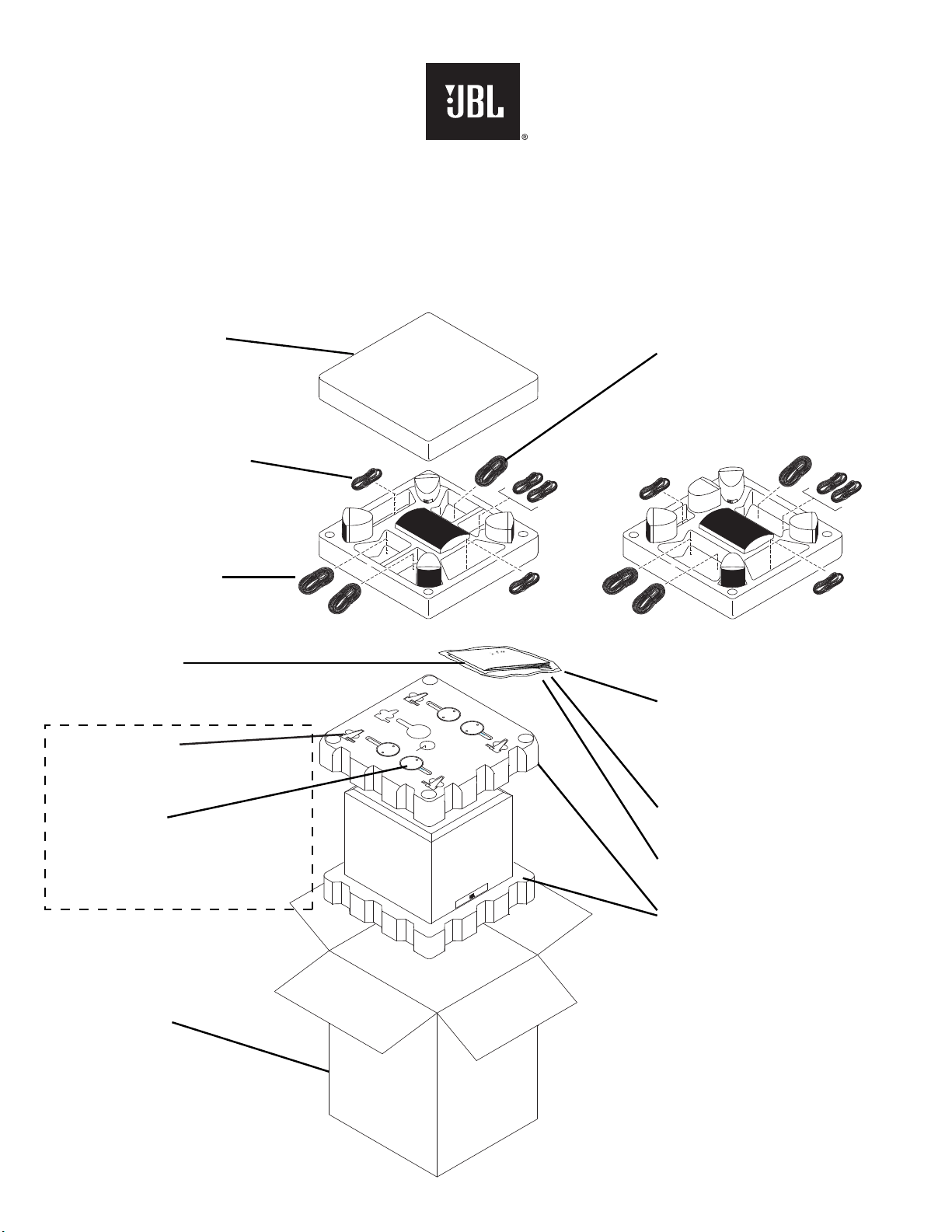
Packaging
SATELLITE STYROFOAM
SCS135/SCS135SI – WP5101
SCS136SI – 431-000-00938
SCS145.5S – 431-000-00420
WIRE SET (SATS & CENTER)
SCS135/SCS135SI – SAL5019
SCS136SI/SCS145.5S – 370-000-00087
WIRE SET (SUB IN/OUT)
SCS135/SCS135SI – SAL063-1
SCS136SI/SCS145.5S – 370-000-00069
WARRANTY CARD
SCS135/SCS135SI – AT5160
SCS136SI/SCS145.5S – 405-000-00258
SUPPORT MURAL
SCS135/SCS135SI – WI0409
SCS136SI/SCS145.5S – 325-FE-00163
WIRE SET (SURROUND)
SCS135/SCS135SI – SAL5009
SCS136SI/SCS145.5S – 370-000-00081
SCS136SI only
OWNER’S MANUAL
SCS135 – AI5073
SCS135SI – AI5193
SCS136SI – 406-000-00889
SCS145.5S – 406-000-05100
WALL BRACKET
SCS135/SCS135SI – WI0408
SCS136SI/SCS145.5S – 372-000-00042
Models SCS135SI/SCS136SI/SCS145.5S
all parts are stored in satellite foam.
OUTER CARTON
SCS135 – WG5164
SCS135SI – WG5362
SCS136SI – 402-000-01767
SCS145.5S – 402-000-05179
SURVEY CARD
SCS135/SCS135SI – AI0193
WALL BRACKET WARNING SHEET
SCS145.5S – 405-000-05021
SUBWOOFER STYROFOAM (2)
SCS135/SCS135SI – WP5110
SCS136SI/SCS145.5S – 431-000-00729
23
 Loading...