

Page 1
INTONATO | 24
Monitor Management Tuning System
Operation Manual
Page 2

Table of Contents
Introduction ����������������������������������������������������������������������1
Features ����������������������������������������������������������������������������3
Front Panel Overview ������������������������������������������������������4
Rear Panel Overview �������������������������������������������������������6
Installing the Intonato 24 �������������������������������������������������9
Rack Installation �������������������������������������������������������������������������9
Making Audio Connections ��������������������������������������������������������9
Applying Power ��������������������������������������������������������������������������9
Installing the JBL Intonato Control App �����������������������10
Device Requirements ���������������������������������������������������������������10
Downloading and Installing the App ������������������������������������������10
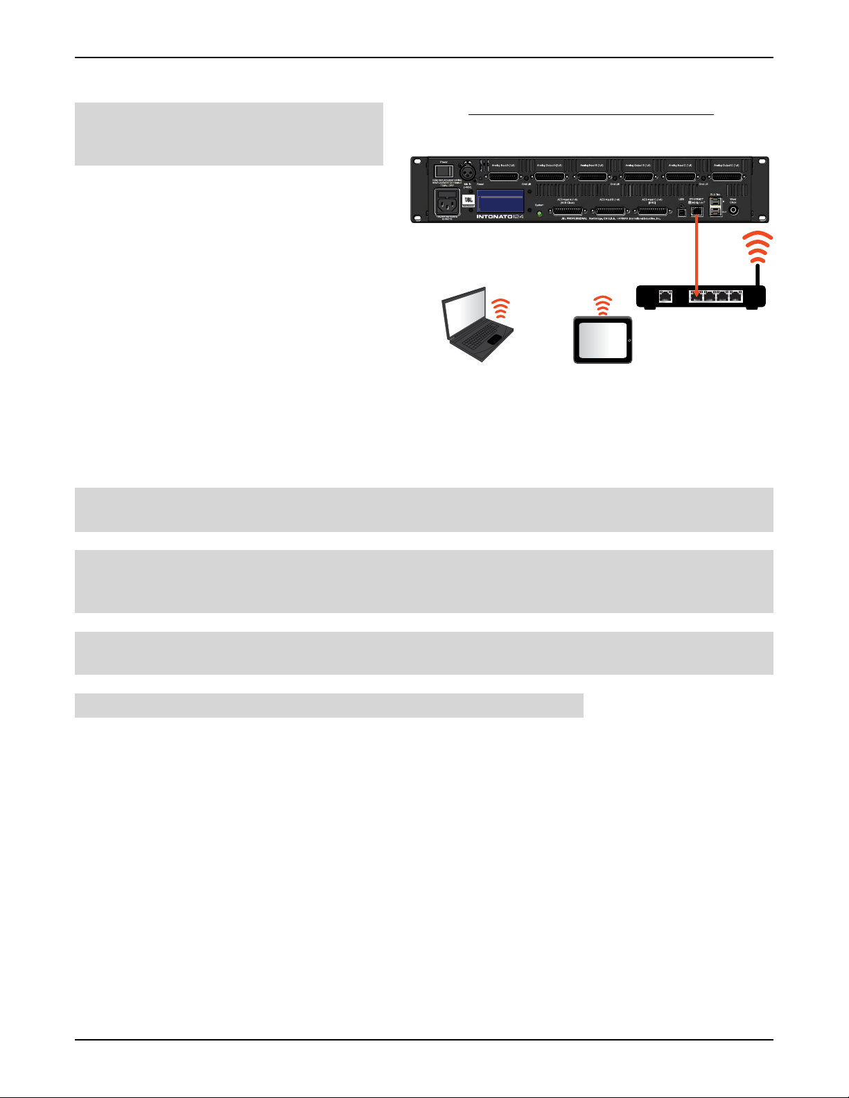
Connecting to the Network �������������������������������������������11
Connecting to a Wired Network Switch or Router ���������������������11
Connecting to a Wi-Fi Network Router ��������������������������������������12
Using the Intonato 24 Control App �������������������������������13
Discovering Devices on the Network �����������������������������������������13
Selecting the Speaker Layout Type �������������������������������������������14
About Speaker Layouts, Profiles, and Scenes �����������������������15
About the Aux Outputs ���������������������������������������������������������16
Configuring Inputs ��������������������������������������������������������������������17
Configuring Outputs �����������������������������������������������������������������19
Configuring Utility Settings ��������������������������������������������������������21
Configuring BLU link Outputs ���������������������������������������������������23
Calibrating the System �������������������������������������������������������������24
User EQ Refinement Recommendations �������������������������������25
Balancing Subwoofers – Bass Management and LFE Levels �26
The System Calibration Screen ���������������������������������������������28
Adjusting User EQ ��������������������������������������������������������������������32
Using Profiles ���������������������������������������������������������������������������34
Creating Scenes ����������������������������������������������������������������������36
Setting the Security Password and Updating Firmware �������������38
The Desktop Controller Screens �����������������������������������������������39
User Control – Master Controls �������������������������������������������������40
User Control – Recalling Scenes �����������������������������������������������43
Configuring the Clock Source ��������������������������������������76
Clocking via the Internal Clock ��������������������������������������������������77
Clocking via AES ����������������������������������������������������������������������78
Clocking via Word Clock ����������������������������������������������������������79
Using BLU link ����������������������������������������������������������������80
BLU link Specifications �������������������������������������������������������������80
Making BLU link Connections ���������������������������������������������������80
BLU link Mastership �����������������������������������������������������������������81
BLU link Fault Tolerance �����������������������������������������������������������81
BLU link Port LED Indicators �����������������������������������������������������82
Configuring Crown DCi Network Series Amplifiers ���������������������83
Speaker Tunings ������������������������������������������������������������87
The Intonato DC Desktop Controller ����������������������������88
Networking ���������������������������������������������������������������������89
Networking Overview ���������������������������������������������������������������89
Network Security ���������������������������������������������������������������������90
Network Troubleshooting ���������������������������������������������������������90
®
Using HiQnet
Configuring the Network Using NetSetter ������������������������������92
NetSetter™ �������������������������������������������������������92
Signal Path Block Diagram �������������������������������������������93
Dimensions ��������������������������������������������������������������������������94
Specifications ����������������������������������������������������������������95
Appendix ������������������������������������������������������������������������97
Replacing the Fuse ������������������������������������������������������������������97
D-Sub Connector Pinouts ��������������������������������������������������������98
Attribution Notices �������������������������������������������������������������������99
Warranty and Service ��������������������������������������������������100
Contact Information ����������������������������������������������������101
Application Examples ����������������������������������������������������44
2�1 Bi-Amplified Application �����������������������������������������������������44
5�1 Full-Range Application �������������������������������������������������������52
7�2 Bi-Amplified Application �����������������������������������������������������60
Dolby Atmos Application ����������������������������������������������������������68
INTONATO | 24 Operation Manual
Page 3

Introduction
Introduction
Thank you for purchasing the JBL® Intonato 24 Monitor Management Tuning System. The Intonato
24 is a powerful, sophisticated speaker management processor and monitor controller for audio
recording, post production, and broadcast facilities. With support for mono to immersive surround
formats, the Intonato 24 provides the centerpiece for a scalable audio production monitoring system.
Supported Formats
The Intonato 24 can be configured for mono, stereo, 5.1, 7.1, and greater surround systems,
including burgeoning immersive audio production formats such as Dolby
DTS:X™, and others that use overhead or height surround speakers. Up to 4 subwoofers are
supported, with LFE capabilities, assignable bass management for each satellite speaker, and global
bass management on/off control. Fully customizable downmixing with adjustable downmixing levels is
also supported, allowing various downmix formats to be recalled using scenes.
Inputs
The Intonato 24 can accept up to 24 simultaneous source inputs from various combinations of the 24
line-level analog, 24 digital AES, and 24 BLU link input channels. AES Input C has selectable sample
rate conversion (SRC), which can be enabled when connecting digital devices synchronized from
different clocks (such as their own).
®
Atmos®, Barco® Auro,
Outputs
Up to 24 line-level analog outputs are available for connecting to the amplifiers. Or, up to 24 BLU link
output channels can be routed to BLU link-equipped amplifiers, such as the Crown Audio
models. Two independently adjustable delays are also provided to synchronize the monitor system
and talent headphone mix to video displays and restore “lip synchronization”.
®
DCi N
Mic Input and Stereo Aux Output
The Intonato 24’s XLR mic input can be used for both calibrating the system and for talkback
communication during recording sessions. The stereo aux output (channels 23 and 24 when
configured) carries the talkback signal and supports channel downmixing, making it perfect for
recording voiceover or automatic dialog replacement (ADR) for surround-formatted projects.
Conguration and Control
The Intonato 24 can be configured and controlled from a compatible Windows®, Mac®, iOS®, or
Android
connecting to a DHCP-enabled network via a wired computer connection or a Wi-Fi router and WiFi-equipped device. User control is also available using the dedicated Intonato DC desktop controller
(sold separately).
The Intonato 24 offers six different speaker layout configuration types and works on the principle of
creating a profile for a given type of session, then creating and storing scenes to the profile for later
recall by the studio engineer.
™
device using the free JBL Intonato control app. Network control can be established by
A profile contains all the configuration settings for a given type of session. Up to 30 profiles can be
stored. Scenes contain the various states the studio engineer will need to recall during a session
(source/speaker monitor selection, fold-down mixes, etc.). Up to 30 scenes can be stored to each
profile.
Within scenes, audio inputs can be routed or mixed to outputs with their levels adjusted as necessary.
This provides a great deal of audio routing flexibility to suit the application.
INTONATO | 24 Operation Manual
Page 1
Page 4

Introduction
For the studio engineer, the Intonato 24 provides master mute, dim, and monitor volume control, as
well as individual speaker mute/solo control, and monitor SPL indication.
Integrated Auto-Calibration System
The Intonato 24 includes a sophisticated auto-calibration system that leverages JBL’s decades of
experience integrating speaker systems into real-world production environments. Based on JBL’s
proprietary software used to measure acoustics during product development, the Intonato 24
incorporates a powerful hardware-based DSP solution designed to produce a “tuned” monitoring
environment that delivers greater accuracy in a broad range of environments.
Using the supplied calibration microphone, the Intonato 24 analyzes the system performance in the
monitoring environment and automatically matches the level, “time-of-arrival” delay, and frequency
response of all speakers. Furthermore, an infinite number of mic position measurements can be taken
to provide an averaged room frequency response, for very complex yet fast and accurate room EQ
calibration.
Differing distances in speaker placement can prevent correlated signals from summing properly at the
mix position. The Intonato 24’s auto-calibration system ensures the output and “time of arrival” of all
speakers is carefully matched. The auto-calibration system measures the level and time of arrival of
each speaker, and applies the precise amount of attenuation and delay to all speakers to match that
of the most distant speaker.
In the low frequencies, the room is in control. Place a speaker in different places in the room and you
will hear differences in low-frequency response. Although a speaker may deliver neutral frequency
response on-axis in an anechoic environment, when measured at the mix position the response is
altered by the interaction of the loudspeaker and the production environment.
“Room modes” or “standing waves” (low-frequency resonance caused by the geometry and
construction of the room) can augment and attenuate low-frequency response, creating a false
impression of bass at the listening position. This issue can result in mixes that are bass-light or bassheavy when auditioned on systems outside the control room.
During the auto-calibration process, the Intonato 24 measures the low-frequency response delivered
by each speaker and applies settings to tackle effects of low-frequency resonance. Additionally the
system identifies and neutralizes response anomalies caused by the speaker’s proximity to the room’s
walls or work surface. The system is designed to identify low-frequency resonance and boundary
issues below 500Hz and adjust the “Room EQ” to provide flat low-frequency response from all
speakers. In our experience, the desired low-frequency curve varies according to room size and
material.
Once system calibration is complete, the Intonato 24’s “User EQ” allows the system’s frequency
response to be tailored according to preference—for example, to compensate for perforated-screen
transmission loss, or to create the X Curve or another custom frequency-response contour.
Page 2
INTONATO | 24 Operation Manual
Page 5

Features
Features
• Support for 44.1, 48, 88.2, and 96 kHz sample rates
• Up to 24 simultaneous inputs from the available 24 analog, 24 AES, and 24 BLU link input
channels
• Up to 24 analog and BLU link output channels
• Sample rate conversion for asynchronous connection of up to 8 AES input signals
• Support for mono, stereo, 5.1, 7.1, and greater surround formats, including burgeoning immersive
audio production formats such as Dolby Atmos, Barco Auro, DTS:X, and more
• Mixing matrix with channel-independent level control for flexible routing, mixing, and downmixing
of any combination of AES, Analog, and BLU link inputs to outputs
• Bi-amped speaker support
• LFE support with adjustable LFE low-pass filter frequency
• Bass Management for up to 4 subwoofers, with global bass management on/off control
• Adjustable bass management crossover frequency
• Included measurement microphone and auto-calibration feature for automated system calibration
of output trims, delays, and 12-band room EQ, with support for an infinite number of mic positions
to provide an averaged room EQ response
• Built-in signal generator with pink noise, white noise, and sine wave tone options
• Manually adjustable 8-band parametric EQ and polarity on every output channel
• Independently adjustable delays for synchronizing speaker and headphone monitoring systems to
video displays
• Stereo aux output with downmixing support, talkback, 3-band EQ, and level control—perfect
for providing a headphone mix to talent for voiceover/ADR recording sessions or feeding remote
stereo speakers
• Store up to 30 profiles
• Store up to 30 scenes in each profile for recall of source/monitor selection and fold-down
monitoring
• End-user control of solo and mute for each speaker output
• End-user control of master level, mute, and dim, with dim level adjustment
• Monitor level calibration with SPL readout for reliable level referencing
• Password protection to prevent unauthorized tampering
• Built-in speaker tunings for the JBL M2 speakers, 7 Series speakers, and various JBL subwoofers
• Unit configuration and control using the free JBL Intonato control app, available for compatible
Windows, Mac, Android, and iOS devices
• Optional dedicated Intonato DC desktop controller available
INTONATO | 24 Operation Manual
Page 3
Page 6
Front Panel Overview
1 2 4
3
Front Panel Overview
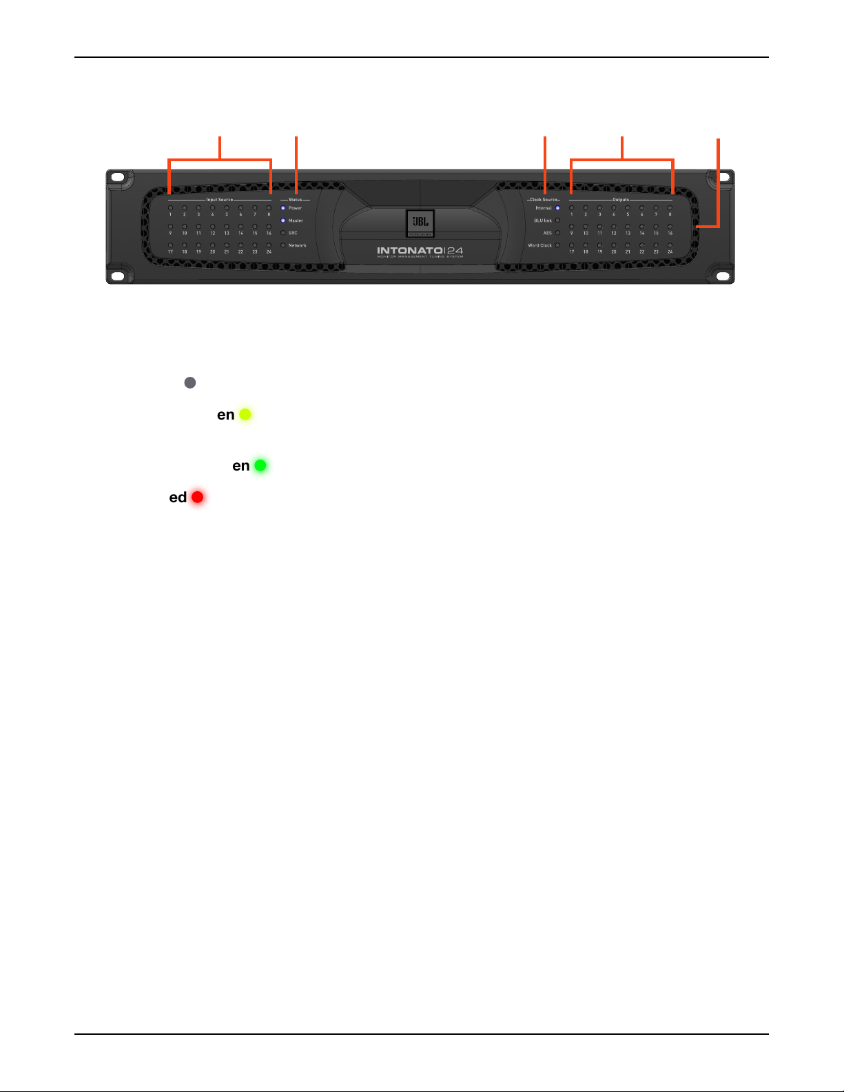
1. Input Source LEDs
These LEDs indicate input signal status of the 24 configured inputs post the A/D converters (if
analog) and before the DSP. Signal status is indicated as follows:
•
LED Off – The input channel is not configured for use in the current scene.
• LED Dim Green – The input channel is configured for use in the current scene, but no signal
is detected.
5
•
LED Bright Green – The input channel detects signal level.
• LED Red – The input channel is clipping.
2. Status LEDs
These LEDs indicate status as follows:
Power – Lights to indicate the unit is powered on.
•
• Master – Lights when the Intonato 24 is providing the master clock for the BLU link bus.
• SRC – Lights to indicate sample rate conversion is enabled on AES Input C.
• Network – Lights to indicate a connection has been established with the network.
3. Clock Source LEDs
These LEDs indicate the source providing master clock to the Intonato 24:
Internal – Lights to indicate the Intonato 24 is clocked from the internal oscillator.
•
• BLU link – Lights to indicate the Intonato 24 is clocked from another device on the BLU link
bus.
•
AES – Lights to indicate the Intonato 24 is clocked from the AES signal connected to AES
Input A1.
•
Word Clock – Lights to indicate the Intonato 24 is clocked from the Word Clock (BNC) input.
Page 4
INTONATO | 24 Operation Manual
Page 7

Front Panel Overview
4. Output LEDs
These 24 output LEDs indicate output signal status post the DSP. Signal status is indicated as
follows:
•
LED Off – The output channel is not configured for use in the current scene.
• LED Dim Green – The output channel is configured for use in the current scene, but no
signal is detected.
•
LED Bright Green – The output channel detects signal level.
• LED Red – The output channel is clipping.
5. Cooling Vents
These vents provide air circulation through the processor. A low-noise fan is used to circulate
air through the Intonato 24 and keep it running at an optimal temperature. The fan is baffled to
appropriately direct airflow and minimize fan noise. When installing the Intonato 24, ensure that all
airflow vents remain unblocked.
INTONATO | 24 Operation Manual
Page 5
Page 8
Rear Panel Overview
Rear Panel Overview
1 2 3 4
IP: 169.254.30.21
Events:
HQ: 2:6:801B SYSTEM BOOT
6 8
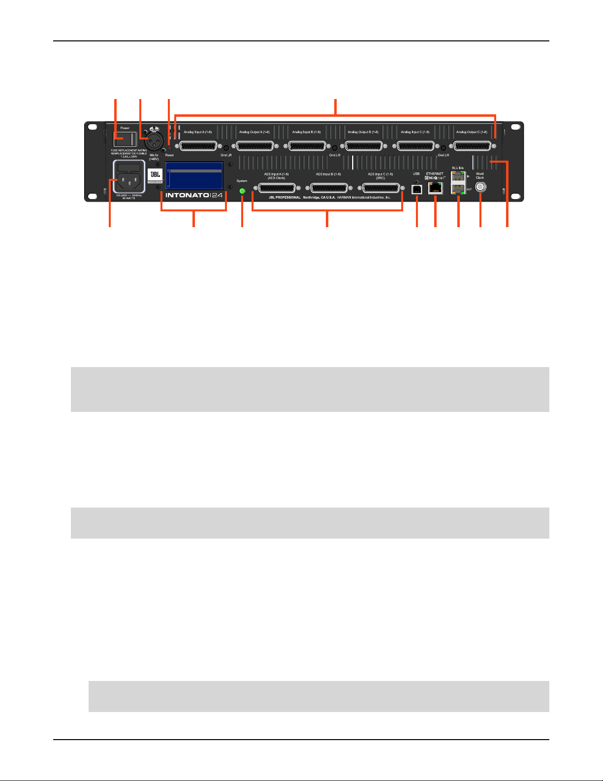
1. Power Switch
97 10 115
12 13
This rocker-type power switch is used to turn the Intonato 24’s power on or off.
2. Microphone Input Connector
This balanced female XLR input serves two purposes: connect the included measurement
microphone to initially calibrate the speaker system to the monitoring environment; connect a
talkback mic to communicate with talent via the stereo aux output during recording sessions.
WARNING: This input supplies a constant 48V phantom power supply. To prevent microphone
damage when connecting a dynamic microphone, ensure that a balanced cable connection is
used.
3. Reset Button
This button is used to perform a factory reset on the unit. The factory reset restores all parameters
to the factory default settings. To perform a factory reset, press and hold the
Reset button while
powering on the Intonato 24. The button must be held until the LCD indicates “Factory Reset”.
Follow the on-screen instructions to complete the factory reset procedure.
WARNING: Performing the factory reset will erase all user-defined settings and presets and is
irreversible.
4. Analog Input and Output Connectors
25-pin female D-Sub connectors are used for the analog inputs and outputs. These connectors
adhere to the industry-standard TASCAM
Pinouts” on page 98
Analog Inputs – Connect the input D-Sub connectors to the analog outputs of the source
•
for more information on the pinouts of these connectors.
®
balanced audio pinouts. See “D-Sub Connector
devices (e.g., mixer, DAW audio interface, D/A converters, reference playback devices,
etc.). Each input connector accepts eight channels of analog audio. These are electronically
balanced inputs with a maximum input level of up to +28 dBu.
NOTE: Analog input sensitivity is selectable per D-Sub connector. See “Analog Input
Sensitivity (A, B, and C)” on page 21
for more information.
Page 6
INTONATO | 24 Operation Manual
Page 9

Rear Panel Overview
Each analog D-Sub input connector has an accompanying Ground Lift button. If hum occurs
at an input, and is due to a ground loop between the Intonato 24 and the connected source
device, engaging the associated Ground Lift button will break the ground loop.
•
Analog Outputs – Connect the output D-Sub connectors to the analog inputs of the amplifiers
or powered speakers, as well as to the headphone amplifier for talent talkback, if applicable.
Each output D-Sub connector carries eight channels of analog audio. These are electronically
balanced outputs with a maximum output level of +24 dBu.
5. Power Input Connector
Connect the power cable to this standard IEC connector to supply power to the unit. This
connector has a built-in fuse to limit exposure to any possible over-current conditions. See
“Replacing the Fuse” on page 97 for information on replacing the fuse.
6. LCD
This liquid crystal display (LCD) indicates the Intonato 24’s current IP address and displays
processor status (e.g., network activity, sample rate, fault conditions, error messages, etc.). It also
displays prompts when performing the factory reset function.
7. System Button/LED
This button is used during the factory reset procedure.
8. AES Inputs
Connect these 25-pin female D-Sub connectors to the AES digital outputs of source devices
(e.g., DAW audio interface, reference playback devices, etc.). Each input connector accepts eight
channels of digital audio. The pinout of these connectors are based on the industry-standard
TASCAM balanced audio pinouts. See
“D-Sub Connector Pinouts” on page 98 for more
information on the pinouts of these connectors.
NOTE: When connecting digital signals to these connectors, the clock is derived from AES Input
A1. Optional sample rate conversion can be enabled on the AES Input C connector, allowing
connection of up to eight asynchronous digital sources (digital sources which are slaved to a
different clock than that connected to AES Input A1).
9. USB Port
This port provides potential update capabilities.
10. Ethernet (HiQnet®) Port
Connect this Ethernet port to a DHCP-enabled network to configure, control, and update the
Intonato 24 via the JBL Intonato control app. End-user control is available via the app or using the
dedicated Intonato DC desktop controller (sold separately).
11. BLU link Input/Output Ports
Connect these RJ45 ports to other BLU link-equipped devices to transmit and receive up to 24
channels of high-resolution digital audio via Ethernet cabling. See
“Using BLU link” on page 80
for more information on using BLU link.
INTONATO | 24 Operation Manual
Page 7
Page 10

Rear Panel Overview
12. Word Clock Input
In cases where an external master (or “house”) clock is used for reference, connect the word clock
output of the master clock device to this BNC connector. See
page 76
13. Cooling Vents
These vents provide air circulation through the processor. A low-noise fan is used to circulate
air through the Intonato 24 and keep it running at an optimal temperature. The fan is baffled to
appropriately direct airflow and minimize fan noise. When installing the Intonato 24, ensure that all
airflow vents remain unblocked.
for information on using word clock.
“Configuring the Clock Source” on
Page 8
INTONATO | 24 Operation Manual
Page 11

Installing the Intonato 24
Installing the Intonato 24
IMPORTANT: Read the important safety instructions included in the box before installing and
operating this product.
Rack Installation
THE INTONATO 24 IS FOR RACK MOUNT USE ONLY. Install the Intonato 24 in a 19” rack with the
provided rack screws and washers. When installed in a rack, ensure that all airflow vents remain
unblocked. The Intonato 24 should not be mounted directly above or below anything that generates
excessive heat. Ambient temperatures should not exceed 104° F (40° C) when equipment is in use.
Although the unit is shielded against radio frequency and electromagnetic interference, extremely high
fields of RF and EMI should be avoided where possible. The Intonato 24 is cooled via an internal lownoise fan optimized for quiet operation.
Making Audio Connections
1. Ensure the power is turned off on all interconnecting equipment and the Intonato 24 before
making audio connections.
2. Connect the outputs of the source devices to the inputs of the Intonato 24. If connecting via
AES digital connections, use 110 ohm cable optimized for AES transmission. For all analog
connections, use the highest quality cables available with the shortest possible cable runs. If
connecting via BLU link, Cat5e or higher cables should be used.
TIP: The Intonato 24 offers selectable analog input sensitivity options, which allow the analog
input gain stages to be optimized for the connected source devices. These analog input
sensitivity settings can be configured from the Utility screen in the control app. See
Input Sensitivity (A, B, and C)” on page 21
3. Connect the Intonato 24’s outputs to the designated amplifier, powered speaker, or headphone
amplifier inputs. Analog and/or BLU link outputs can be used, depending on the application.
4. If the system will be calibrated using the built-in auto-calibration feature, connect the included
measurement microphone to the XLR mic input using a balanced microphone cable of suitable
length and place it in a microphone stand.
for more information.
“Analog
Applying Power
1. Ensure your sources are powered on and turned down.
2. Connect a power cable to the AC power inlet on the Intonato 24’s back panel, then connect the
other end to an available AC power outlet.
3. Switch the back-panel power switch to the on position.
4. Apply power to the power amplifiers or powered speakers.
INTONATO | 24 Operation Manual
Page 9
Page 12

Installing the JBL Intonato Control App
Installing the JBL Intonato Control App
The free JBL Intonato control app is used to program and control the Intonato 24. It is available for
compatible Android, iOS, Mac, and Windows devices.
Device Requirements
Visit http://www.jblpro.com/intonato24 for the latest information on device requirements for the JBL
Intonato control app.
Downloading and Installing the App
Download and install the JBL Intonato control app from the iTunes Store®, Google Play™, or from
http://www.jblpro.com/intonato24.
Page 10
INTONATO | 24 Operation Manual
Page 13
Connecting to the Network
IP: 169.254.30.21
Events:
HQ: 2:6:801B SYSTEM BOOT
WAN LAN
1 2 3 4
Ethernet Router w/DHCP
Intonato 24
Mac® or Windows®
Computer
Mac
®
Computer With Wi-Fi
IP: 169.254.30.21
Events:
HQ: 2:6:801B SYSTEM BOOT
or
Intonato 24
Wi-Fi Router w/DHCP
WAN LAN
1 2 3 4
Mac® or Windows®
Computer With Wi-Fi
Compatible Android
™
or iOS® Device
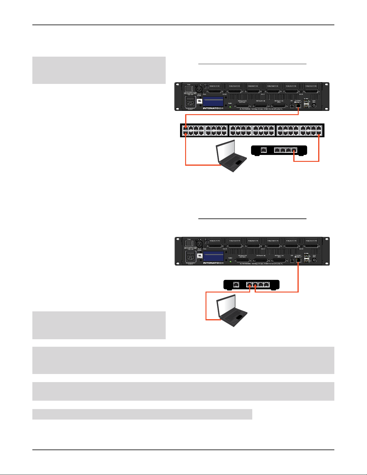
Connecting to a Wired Network Switch or Router
Connecting to the Network
NOTE: The Intonato 24 must be
connected to a DHCP-enabled network for
initial configuration and control.
1. If using a switch, connect one of the
LAN ports from a DHCP-enabled router
to one of the ports on the switch, or
connect it to another switch on the
network.
2. Connect a Cat5, Cat5e, or Cat6 Ethernet
cable to the Ethernet port on the
Intonato 24.
3. Connect the other end of the Ethernet
cable to one of the LAN ports on the
switch or router.
4. Connect your computer’s Ethernet port
to one of the other LAN ports on the
switch or router using a Cat5, Cat5e, or
Cat6 cable.
5. Apply power to the Intonato 24 and wait
for the processor to initialize. Give the
unit time to negotiate with the network
so it can be assigned an IP address. This
can take a few minutes. Look at the LCD
screen on the back of the unit to ensure
the Intonato 24 has been assigned an IP
address.
Wired Network Switch Connection
Intonato 24
IP: 169.254.30.21
Events:
HQ: 2:6:801B SYSTEM BOOT
Ethernet Switch
®
Mac
or Windows®
Computer
Ethernet Router w/DHCP
1 2 3 4
WAN LAN
Wired Network Router Connection
Intonato 24
IP: 169.254.30.21
Events:
HQ: 2:6:801B SYSTEM BOOT
Ethernet Router w/DHCP
1 2 3 4
WAN LAN
NOTE: For more information on
networking, including troubleshooting tips,
see
“Networking” on page 89.
TIP: Once connection to the network has been established using a DHCP server, the HiQnet
Mac® or Windows®
Computer
®
NetSetter™ application can be used to assign the Intonato 24 a static IP address if required for the
application. See
NOTE: The Intonato 24 can establish a network connection with the Intonato DC desktop controller
“Using HiQnet® NetSetter™” on page 92 for more information.
and control app simultaneously.
WARNING: Only connect to networks that remain inside the building.
INTONATO | 24 Operation Manual
Page 11
Page 14
Connecting to the Network
Intonato 24
Connecting to a Wi-Fi Network Router
NOTE: The Intonato 24 must be
connected to a DHCP-enabled network for
initial configuration and control.
Wi-Fi Network Router Connection
1. Connect a Cat5, Cat5e, or Cat6 Ethernet
IP: 169.254.30.21
Events:
HQ: 2:6:801B SYSTEM BOOT
cable to the Ethernet port on the Intonato
24.
2. Connect the other end of the Ethernet
cable to one of the LAN ports on the WiFi router.
3. Connect to the Wi-Fi network using your
Wi-Fi-equipped computer or device.
4. Apply power to the Intonato 24 and wait
for the processor to initialize. Give the unit
Mac® or Windows®
Computer With Wi-Fi
Wi-Fi Router w/DHCP
or
Compatible Android
or iOS® Device
1 2 3 4
WAN LAN
™
time to negotiate with the network so it
can be assigned an IP address. This can
take a few minutes. Look at the LCD screen on the back of the unit to ensure the Intonato 24 has
been assigned an IP address.
NOTE: For more information on networking, including troubleshooting tips, see “Networking” on
page 89
.
TIP: Once connection to the network has been established using a DHCP server, the HiQnet
NetSetter application can be used to assign the Intonato 24 a static IP address if required for the
application. See
“Using HiQnet® NetSetter™” on page 92 for more information.
NOTE: The Intonato 24 can establish a network connection with the Intonato DC desktop controller
and control app simultaneously.
WARNING: Only connect to networks that remain inside the building.
Page 12
INTONATO | 24 Operation Manual
Page 15
Using the Intonato 24 Control App
Using the Intonato 24 Control App
The Intonato 24 is configured using the JBL Intonato control app. For information on downloading and
installing the JBL Intonato control app, see
The following sections describe, in order, how to configure and use the Intonato 24 processor.
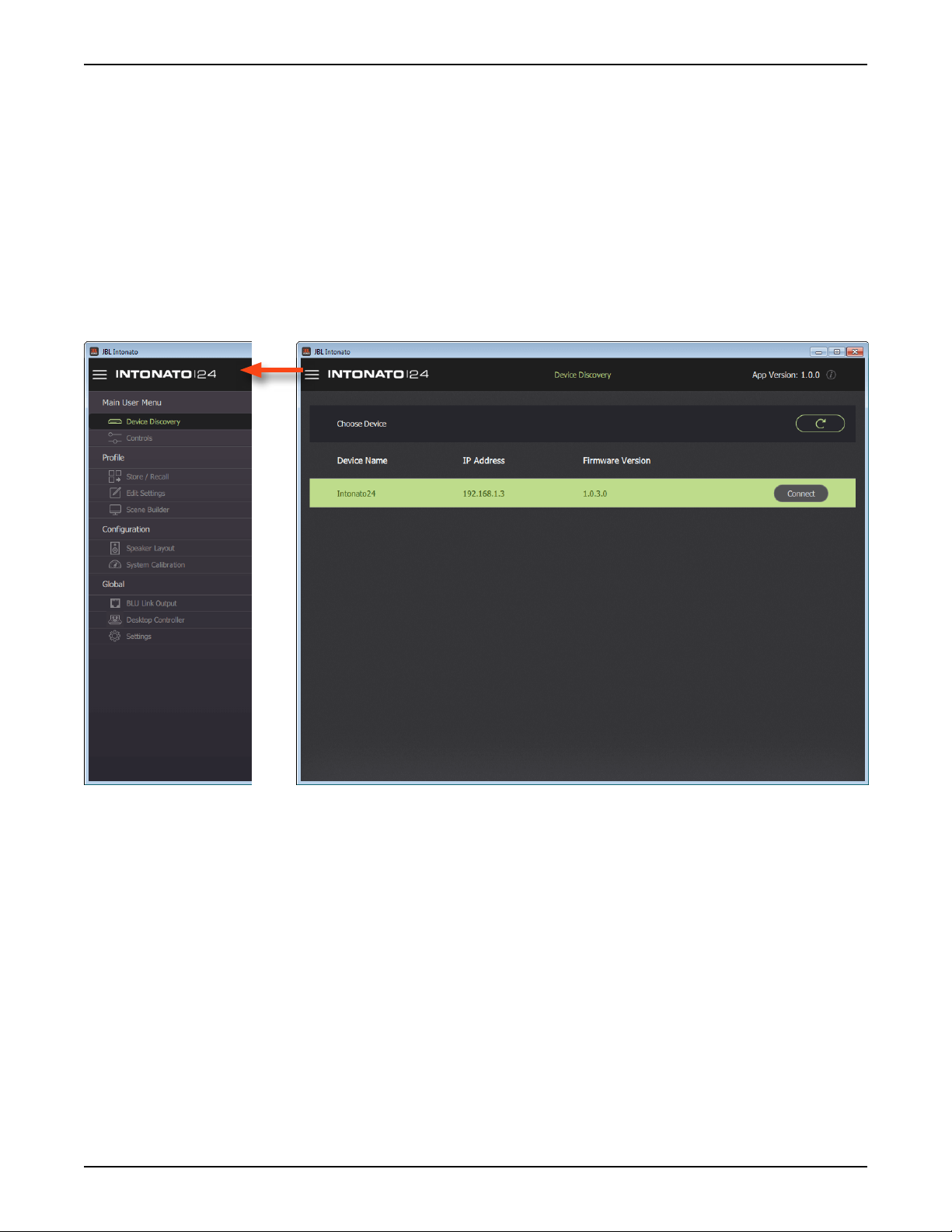
Discovering Devices on the Network
The Device Discovery screen is the first screen that appears once the JBL Intonato control app has
initialized. The app will search the network for connected Intonato 24 devices and list them on this
screen. You can always come back to this screen by selecting
Menu.
“Installing the JBL Intonato Control App” on page 10.
Device Discovery in the Main User
Refresh Button
Press this button to refresh the list of devices detected on the network.
Device List
This list displays all Intonato 24 devices detected on the network, as well as their currently configured
IP address and firmware version. Press the
INTONATO | 24 Operation Manual
Connect button to connect to a device.
Page 13
Page 16
Using the Intonato 24 Control App
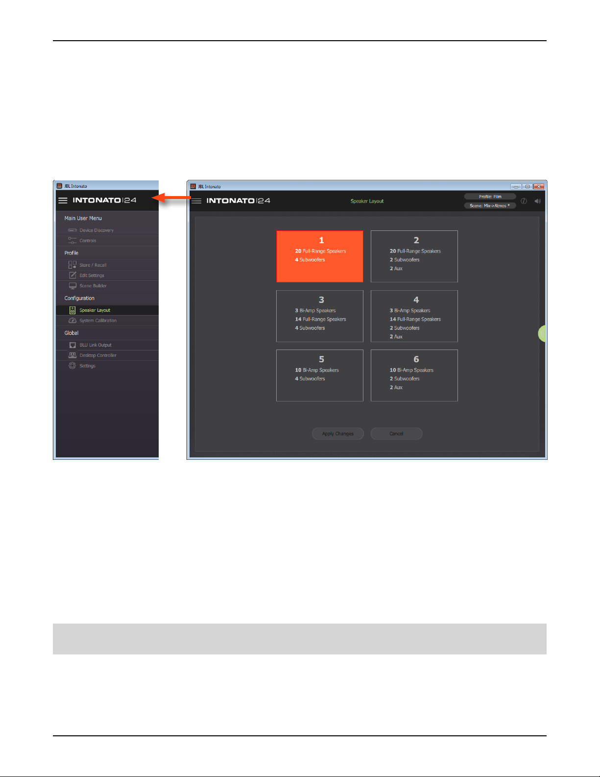
Selecting the Speaker Layout Type
The first step in configuring the Intonato 24 is to select the speaker layout that suits the application:
1. When connecting to the Intonato 24 for the first time, the control app will automatically navigate to
the Speaker Layout screen. If a speaker layout was previously selected and needs to be changed,
select
2. Select the speaker layout that suits the application.
3. Press the Apply Changes button.
Speaker Layout from the Main User Menu.
There are six speaker layout types to choose from:
1. 20 full-range speakers, 4 subwoofers
2. 20 full-range speakers, 2 subwoofers, and 2-channel aux output with talkback
3. 3 bi-amplified speakers, 14 full-range speakers, 4 subwoofers
4. 3 bi-amplified speakers, 14 full-range speakers, 2 subwoofers, and 2-channel aux output with
talkback
5. 10 bi-amplified speakers, 4 subwoofers
6. 10 bi-amplified speakers, 2 subwoofers, and 2-channel aux output with talkback
TIP: See “Application Examples” on page 44 to see example applications using some of the
speaker layouts listed above.
Page 14
INTONATO | 24 Operation Manual
Page 17
Using the Intonato 24 Control App
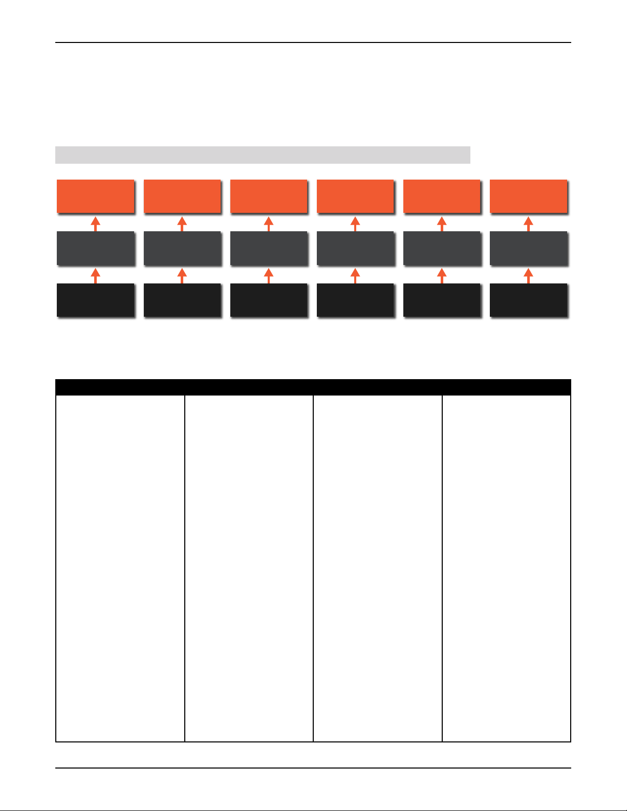
About Speaker Layouts, Proles, and Scenes
Profiles and scenes are stored to the speaker layout type selected during configuration. Up to 30
profiles can be stored to each of the six speaker layout types, and up to 30 scenes can be stored to
each of the 30 profiles (see illustration below). Although it is not typical to change the speaker layout
type once configured, unless the speaker system is being upgraded, this does provide a means to
retain profile and scene settings if the speaker layout type is changed.
NOTE: Profiles and scenes cannot be transferred between speaker layout types.
Speaker Layout
1
30 Profiles
30 Scenes
Per Profile
Speaker Layout
2
Speaker Layout
3
Speaker Layout
4
Speaker Layout
5
Speaker Layout
30 Profiles 30 Profiles 30 Profiles 30 Profiles 30 Profiles
30 Scenes
Per Profile
30 Scenes
Per Profile
30 Scenes
Per Profile
30 Scenes
Per Profile
30 Scenes
Per Profile
6
The table below shows the settings stored to the speaker layout, profiles, and scenes, and which
settings are persistent (their state/value doesn’t change as profiles and scenes are recalled, but will be
defaulted if another speaker layout type is loaded or the unit is power cycled).
Speaker Layout Profiles Scenes Persistent
• System calibration settings
(room EQ, time-alignment
delay, output level, polarity)
• Reference level user
calibration offset setting
(used to calibrate the
measured SPL readout)
• BLU link output channel
assignments
• All stored profile and scene
settings
• Input channel names,
routing, and group
assignments
• Input LFE assignments
• Input trim levels
• Output channel names,
group assignments, bass
management assignments,
and speaker tuning
selections
• Outputs assigned for
master volume control
• User EQ settings for each
output
• Analog input sensitivity,
clock source, sample rate,
and SRC enable
• AV and Aux AV delay
• Bass management
crossover frequency and
LFE low-pass frequency
• Global bass management
on/off, dim level, and
master reset level
• Aux output level and tone
(EQ) settings
• Settings for all scenes (30
per profile)
• All input and LFE mix
level settings in the Scene
Builder screen
• Master volume, dim, and
mute
• Speaker mute/solo
selections
INTONATO | 24 Operation Manual
Page 15
Page 18

Using the Intonato 24 Control App
About the Aux Outputs
When speaker layout 2, 4, or 6 is selected, Intonato 24 output channels 23 and 24 are configured
to provide a stereo auxiliary feed, which can be connected to an external headphone amplifier for
recording sessions (for example, during voiceover or ADR recording sessions in an editing facility
where a mixing console is not available). The feed can also be used to send a mix to a pair of
speakers in a remote location.
A 24 x 2 mixer allows any combination of inputs to be mixed to the stereo aux output, including
downmixed surround mixes. The stereo aux output has its own level control, 3-band EQ, and AV
delay to restore “lip synchronization” with video displays.
Additionally, the XLR mic input is routed to the aux outputs and becomes active when the Talkback
button is pressed. Input 24 will automatically be switched to carry the signal from the XLR mic input.
The talkback input assignment is fixed and cannot be changed. The XLR mic input gain is fixed at 30
dB.
Page 16
INTONATO | 24 Operation Manual
Page 19
Using the Intonato 24 Control App
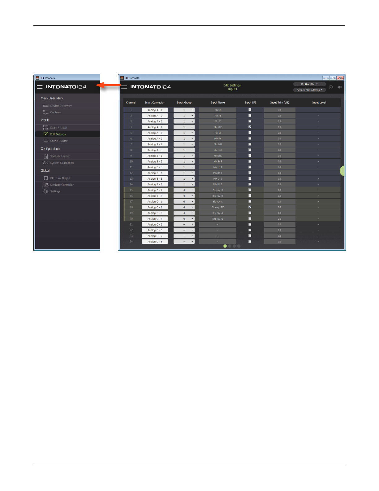
Conguring Inputs
Once the speaker layout type has been selected, it’s time to configure the inputs for the application.
The inputs can be configured by selecting
Configuration screen is the first screen displayed from this menu.
Edit Settings from the Main User Menu. The Input
Information and Navigation Bar
The bar across the top of the screen provides important feedback and access to navigation and
is available on most screens. Press the icon in the upper left-hand corner to access the Main User
Menu and navigate the various screens. The title of the current screen is displayed in the middle of the
bar. In the upper right-hand corner, the currently loaded profile and scene preset are displayed. If an
asterisk appears next to the profile or scene preset, this indicates it has been edited from the stored
values. The information icon accesses the application’s contextual help. The speaker icon can be
used to mute all outputs (with the exception of the stereo aux output).
Input Connector
From these dropdown menus, select the desired physical input to route to each corresponding
Intonato 24 input channel. There is no limitation on the mix of Analog, AES, and BLU link inputs; they
can be assigned in any order.
Input Group
Select from the 12 options available in this dropdown menu to visually group input channels by color.
Input Name
These fields allow inputs to be named to suit the application, which will simplify configuration and
operation.
Input LFE
Check any of these boxes to identify the corresponding input as an LFE channel. When checked, the
INTONATO | 24 Operation Manual
Page 17
Page 20

Using the Intonato 24 Control App
input channel will be routed through the LFE low-pass filter and on to the subwoofer outputs. Any
number of inputs can be designated as LFE input channels.
NOTE: Ensure subwoofers are set to LFE mode, if applicable.
NOTE: The LFE signal level must also be set in the Scene Builder screen to feed the LFE input
signal to the subwoofer(s). See
Builder.
“Creating Scenes” on page 36 for information on using the Scene
Input Trim
Adjust these fields to trim the incoming signal level for each channel. The range is -100 to +10 dB.
Input Level
These readouts display real-time input signal level for each channel.
Master Section Tab
The tab on the right shows or hides the master section controls.
Page 18
INTONATO | 24 Operation Manual
Page 21
Using the Intonato 24 Control App
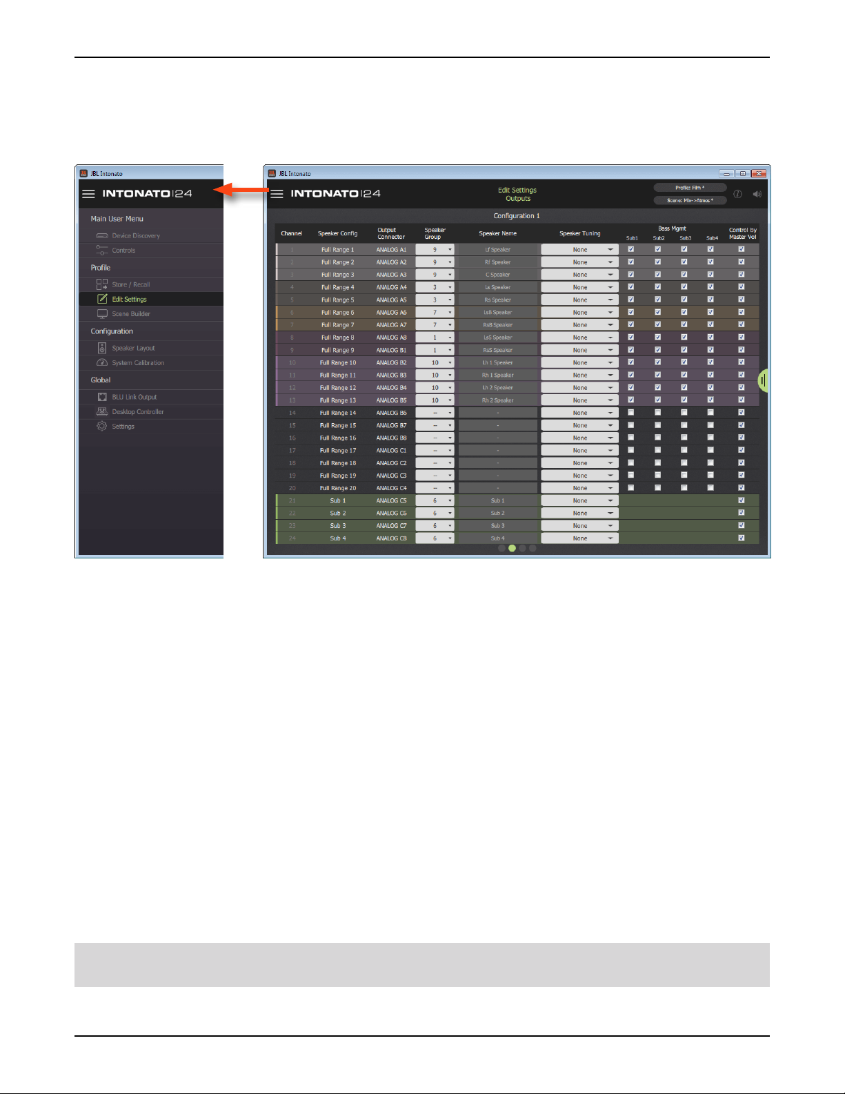
Conguring Outputs
The next step is to configure the Intonato 24 outputs. The Output Configuration screen can be
accessed by selecting
swiping or selecting the second bubble at the bottom.
Edit Settings from the Main User Menu, then going to the second screen by
Speaker Conguration
These fields display the type of output configured for each output channel per the selected speaker
layout.
Output Connector
These fields display the physical output channels as they relate to the analog D-Sub output
connectors.
Speaker Group
Select from the 12 options available in this dropdown menu to visually group speaker output channels
by color.
Speaker Name
These fields allow outputs to be named to suit the application, which will simplify configuration and
operation.
Speaker Tuning
From this dropdown menu, the speaker tuning for the connected speaker model can be selected if
available.
NOTE: The Intonato 24 comes preloaded with speaker tunings for the JBL M2 Series, 7 Series, and
various JBL subwoofers. See
“Speaker Tunings” on page 87 for more information.
INTONATO | 24 Operation Manual
Page 19
Page 22

Using the Intonato 24 Control App
Bass Management (Sub1, Sub2, etc.)
Checking a checkbox in this column will configure the channel to be bass managed to the assigned
subwoofer whenever the master Bass Management button is enabled. When bass management is
enabled, a crossover will be applied to split the signal between the satellite and subwoofer speakers.
The crossover frequency can be adjusted using the Bass Management Crossover Frequency
parameter on the Utility screen.
Control by Master Volume
Each channel checked in this column will be controllable by the studio engineer when adjusting the
master volume controls (Master Volume, Dim button, and Mute button).
Master Section Tab
The tab on the right shows or hides the master section controls.
Page 20
INTONATO | 24 Operation Manual
Page 23
Using the Intonato 24 Control App
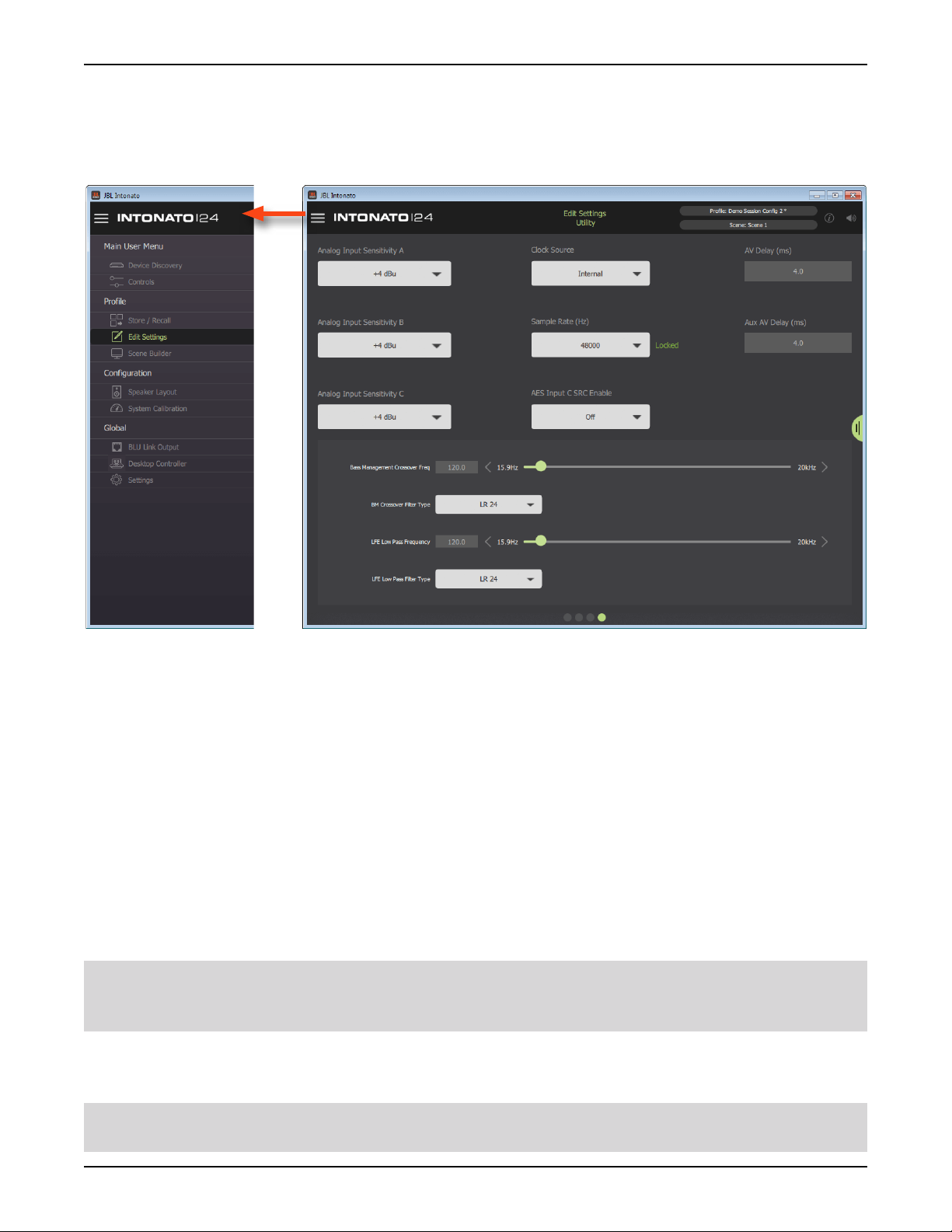
Conguring Utility Settings
The next step is to configure the Intonato 24 utility settings. The Utility screen can be accessed by
selecting
selecting the fourth bubble at the bottom.
Edit Settings from the Main User Menu, then going to the fourth screen by swiping or
Analog Input Sensitivity (A, B, and C)
These dropdown menus adjust the input sensitivity for each of the analog D-Sub input connectors.
Adjust these settings to match the source output levels for optimal signal-to-noise ratio and
headroom. There are three options to choose from:
• -10 dBV (with 18 dB of headroom)
• +4 dBu (with 20 dB of headroom)
• +8 dBu (with 24 dB of headroom)
Clock Source
This dropdown menu selects the source that will provide master clock to the Intonato 24. The options
are Internal, AES (Input 1), and Word Clock (BNC). See
for information on setting this parameter to suit the application requirements.
76
WARNING: When clocking to an AES or word clock signal, always mute the Intonato 24 outputs
before changing the external clock’s sample rate to prevent unwanted noise through the speaker
system.
“Configuring the Clock Source” on page
Sample Rate
This dropdown menu selects the internal processing sample rate.
NOTE: When slaving to an AES or word clock signal, the external clock’s sample rate will be
detected and will override this setting.
INTONATO | 24 Operation Manual
Page 21
Page 24

Using the Intonato 24 Control App
NOTE: When using BLU link, all devices on the BLU link bus must be configured with the same
sample rate setting.
AES Input C SRC Enable
This dropdown menu turns sample rate conversion on AES Input C on or off. When enabled, the
SRC LED on the front panel will light. See
information on using the SRC feature.
“Configuring the Clock Source” on page 76 for more
AV Delay
This parameter applies a delay to the audio signal to compensate for latency in video displays and
restore “lip synchronization”. The AV Delay parameter affects all output channels, with the exception of
the stereo aux output, and has a range of 0–170 ms.
Aux AV Delay
This parameter applies a delay to the audio signal to compensate for latency in video displays and
restore “lip synchronization”. The Aux AV Delay parameter affects only the stereo aux output and has
a range of 0–170 ms.
Bass Management Crossover Frequency Slider
This parameter sets the crossover frequency between the satellite speakers configured for bass
management and subwoofer(s).
Bass Management Crossover Filter Type
This dropdown selects the low-pass and high-pass filter types for the bass management crossover.
The selectable options are Bessel 6, 12, 18, 24, 30, 36, 42, 48, Butterworth 6, 12, 18, 24, 30, 36, 42,
48, Linkwitz-Riley 12, 24, 36, and 48. The numerical values indicate the slope rate in dB/octave.
LFE Low Pass Frequency Slider
This parameter sets the low-pass filter frequency for LFE signals assigned to the subwoofer(s).
NOTE: Ensure subwoofers are set to LFE mode, if applicable.
LFE Low Pass Filter Type
This dropdown selects the filter type for the LFE low-pass filter. The selectable options are Bessel 6,
12, 18, 24, 30, 36, 42, 48, Butterworth 6, 12, 18, 24, 30, 36, 42, 48, Linkwitz-Riley 12, 24, 36, and
48. The numerical values indicate the slope rate in dB/octave.
TIP: When using bass management and LFE channels, it’s important to balance the bass managed
and LFE signal levels properly. See
on page 26
for more information.
“Balancing Subwoofers – Bass Management and LFE Levels”
Master Section Tab
The tab on the right shows or hides the master section controls.
Page 22
INTONATO | 24 Operation Manual
Page 25
Using the Intonato 24 Control App
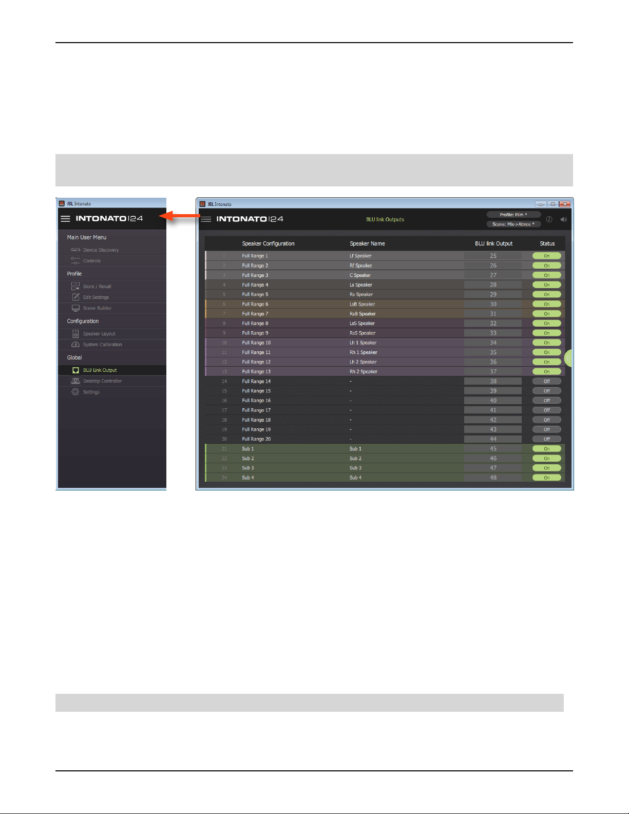
Conguring BLU link Outputs
If the application requires BLU link output from the Intonato 24, BLU link output settings should be
configured next by selecting
From the BLU Link Output screen, up to 24 BLU link channels can be assigned to the BLU link bus.
To assign BLU link output channels, select the BLU link output channel to assign then enable the
Status button for each.
NOTE: Output signals are always present on the analog D-Sub output connectors and are simply
mirrored to any assigned BLU link channels.
BLU Link Output from the Main User Menu.
Speaker Conguration
These fields display the type of output configured for each output channel per the selected speaker
layout.
Speaker Name
These fields display the name given to each speaker output.
BLU link Output
These fields select the BLU link channel to be assigned to each output.
Status
These buttons turn each BLU link output on or off. When turned off, no signal will be passed to the
BLU link bus.
NOTE: The above settings are global and will not be affected when loading profiles or scenes.
Master Section Tab
The tab on the right shows or hides the master section controls.
INTONATO | 24 Operation Manual
Page 23
Page 26

Using the Intonato 24 Control App
Calibrating the System
Once configuration is complete, the next step is to run the auto-calibration process. When used in
conjunction with the included measurement microphone, a monitoring system can be automatically
calibrated to the production environment.
The auto-calibration process starts by detecting level differences between speakers in the system
and adjusting levels to match. Then, time-of-arrival differences between each speaker placement and
the listening position are detected and compensated for using delays. The final stage is to analyze
each speaker and adjust the room equalization to fine-tune each speaker’s frequency response to the
environment. Note that all parameters are also available for manual adjustment.
Follow these steps to automatically calibrate the system:
CAUTION: The use of hearing protection is recommended during the auto-calibration process.
System calibration test tones may generate sound pressure level in excess or 85 dB, which can be
painful to the ears when experienced for extended periods of time.
NOTE: The auto-calibration process cannot correct for speaker polarity issues. Ensure all balanced
audio cables and speaker wires are properly wired and connected before calibrating the system.
1. Connect the included measurement microphone to the XLR mic input using a balanced
microphone cable of suitable length and place it in a microphone stand.
2. Place the microphone at the main listening position.
3. Select System Calibration from the Main User Menu.
4. Press the Run Auto Calibration button and follow the on-screen instructions to calibrate the
system.
NOTE: The Room EQ will analyze frequencies up to 800 Hz and adjust center frequencies up to
approximately 750 Hz when running the auto-calibration process.
TIP: When running the auto-calibration process, an infinite number of mic positions can
be measured to achieve an averaged frequency response. For more accurate results, it is
recommended to measure at least three different mic positions.
5. Once system calibration is complete, make manual setting adjustments from the System
Calibration screen if required.
TIP: Any further refinements to the system’s frequency response should be made using the
User EQ so as to not disturb the calibrated Room EQ settings. See
Recommendations” on page 25
for more information.
“User EQ Refinement
TIP: The monitor system reference level readout can be calibrated using the User Calibration Offset
slider found on the Signal Generator screen. See
information on calibrating this reference level readout.
TIP: If the Intonato 24 limiters need to be used for speaker protection, the limiter threshold will need
to be calibrated. See
threshold.
Page 24
“Limiter Threshold” on page 29 for information on calibrating the limiter
INTONATO | 24 Operation Manual
“The Signal Generator Screen” on page 30 for
Page 27

Using the Intonato 24 Control App
User EQ Renement Recommendations
Low Frequencies
After performing auto calibration, we recommend evaluating the low-frequency performance of the
system by listening to material with which you are familiar. While the system is designed to deliver
flat low-frequency response in the room, different room sizes require differing compensation. After
removing the energy contributed by the interactions of speakers and resonant properties of the room,
you may notice the program content lacks the expected low-frequency response.
The User EQ can be used to produce your ideal in-room response. If you notice the material lacks an
expected low-frequency contour, we recommend applying the following settings to all speakers in the
system:
• Type: Low Shelf
• Frequency: 95 Hz
• Slope: 9 dB/octave
• Gain: +2 dB to +6 dB (Apply the amount of gain required to restore the expected low-frequency
energy.)
Adjustments may vary as follows:
• Frequency: 90 Hz to 110 Hz
• Slope: From 6 dB/octave to 12dB/octave
Applying the aforementioned User EQ settings in addition to the calibrated Room EQ settings should
provide a neutral mix environment.
High Frequencies
In the midrange and high frequencies, the speaker is in control. In the low frequencies, the room is in
control. While the reflectivity or absorptive qualities of the room may affect the overall high-frequency
energy of the speaker system, the User EQ (found in the Edit Settings menu) allows project-specific
and client-specific equalization to be applied, without disturbing the Room EQ settings applied during
the auto-calibration process.
Depending on the size and acoustic characteristics of the room, reflectivity vs absorptive qualities,
and perforated-screen transmission loss, attenuation or boost of the high-frequency response may be
desirable. Additionally, the X Curve or another custom frequency-response contour may be required
for the application. This should be applied using the User EQ.
For more information on using the User EQ, see
“Adjusting User EQ” on page 32.
INTONATO | 24 Operation Manual
Page 25
Page 28
Using the Intonato 24 Control App
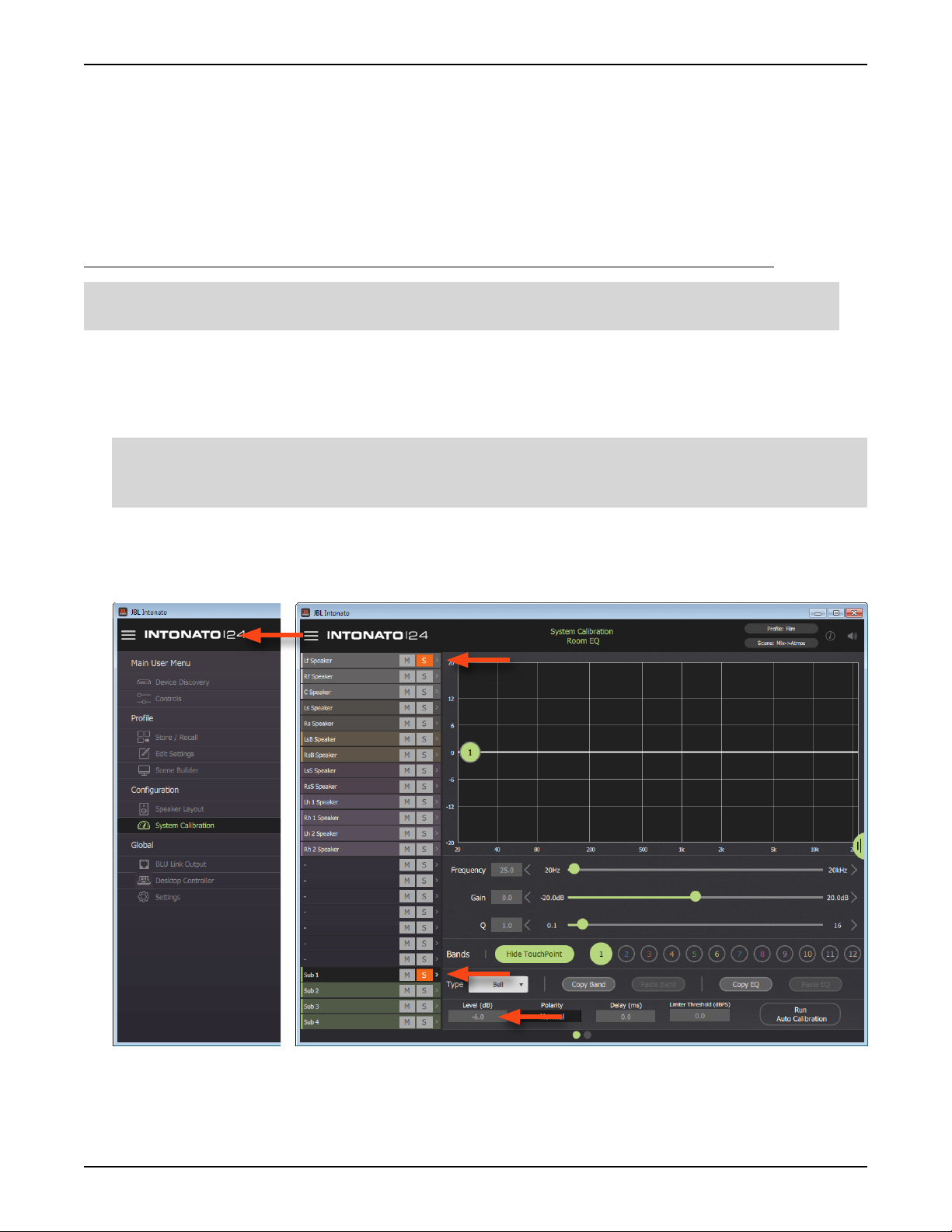
Balancing Subwoofers – Bass Management and LFE Levels
When using bass management and LFE channels, it’s important to balance the levels between
the two properly. Up to four subwoofers may be used for bass management—extending the lowfrequency response of the speaker system. Additionally, the same subwoofers can be assigned to
reproduce the LFE (Low Frequency Effects) channels of one or more playback sources. When using a
sub for both purposes, levels should be calibrated as described below.
To calibrate bass management and LFE signal levels for the subs, follow these steps:
NOTE: Auto calibration should be performed before calibrating the bass management and LFE
levels. See
1. Ensure Bass Management is enabled and play broadband source material—with which you
are familiar—through the system. Ensure that no signal is being sent to the LFE channel. Select
System Calibration from the Main User Menu, then solo the first sub and one of the main satellite
speakers in the left-hand column.
NOTE: If using only one subwoofer, solo both the left and right front satellite speakers along with
the sub to account for the ~3 dB increase in signal level due to summation of the two satellite
speakers vs the single subwoofer.
Select the first sub from the left-hand column and adjust the sub’s
subwoofer response with the bass-managed satellite speaker(s) to produce the desired bassmanaged response. When properly balanced, the subwoofer and the speaker(s) should behave as
a single speaker with extended low-frequency response. Repeat for any additional subwoofers.
“Calibrating the System” on page 24.
Level setting to balance the
2. Once all bass management sub levels have been calibrated, un-solo the channels so that all
channels are again audible.
Page 26
INTONATO | 24 Operation Manual
Page 29
Using the Intonato 24 Control App
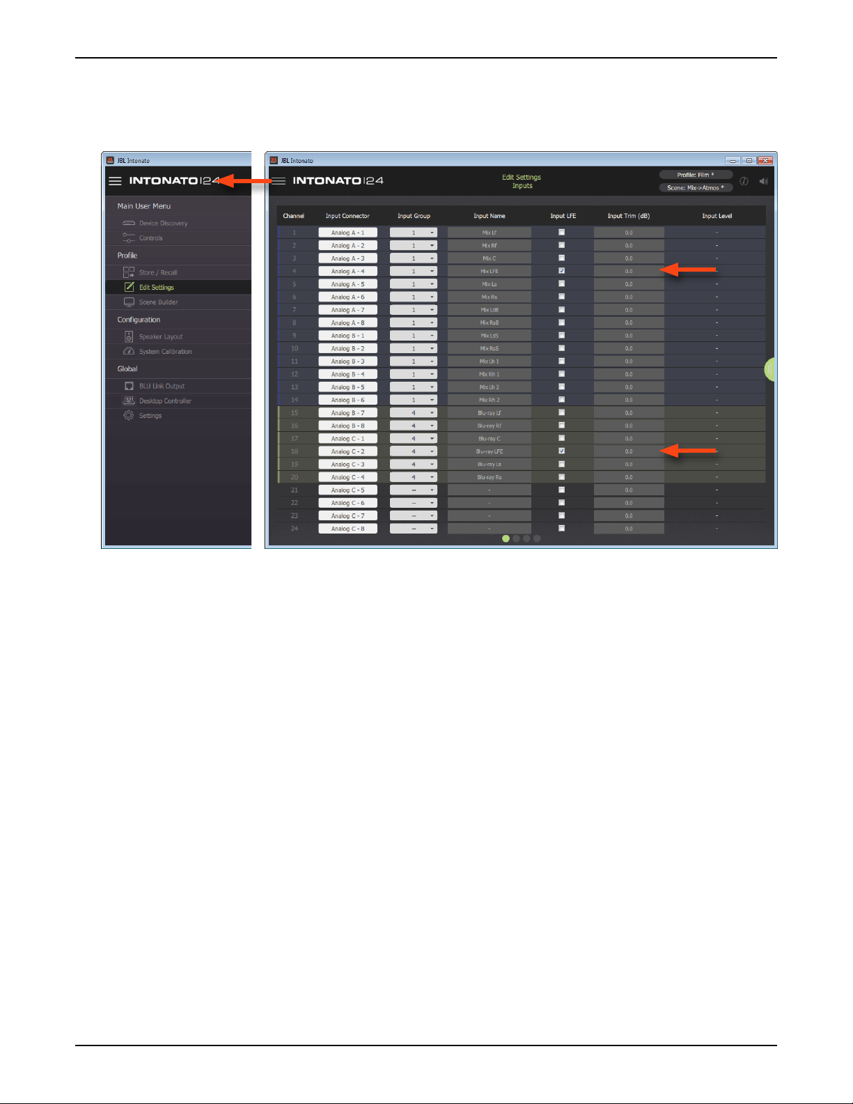
3. Next, play some source material that includes LFE signal, and ensure the LFE signal is passing
through the system. Select
control of the LFE channel to produce the desired SPL in the room. Repeat for any additional
source LFE channels.
Edit Settings from the Main User Menu, then adjust the Input Trim
INTONATO | 24 Operation Manual
Page 27
Page 30
Using the Intonato 24 Control App
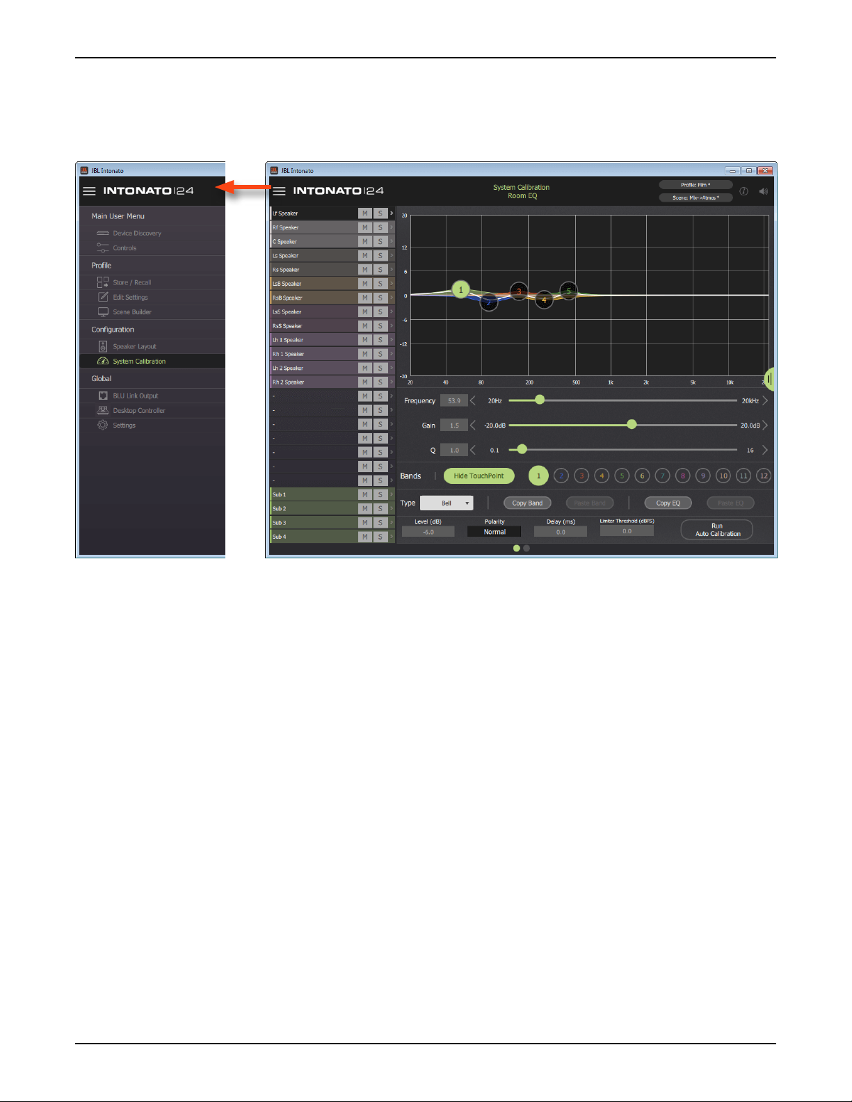
The System Calibration Screen
From the System Calibration screen, individual speaker levels, time-of arrival delay offsets, and room
EQ can be automatically calibrated and/or manually adjusted for the monitoring environment. To
access the System Calibration screen, select
System Calibration from the Main User Menu.
Channel Selection (Leftmost Column)
This column allows an output channel to be selected for editing.
Mute and Solo Buttons
The Mute (M) and Solo (S) buttons can be used to mute or solo output channels. Multiple channels
can be muted or soloed simultaneously.
Graph
This graph displays a graphical representation of the Room EQ curve, with touchpoints that can be
selected and dragged to adjust settings graphically.
Frequency Slider
This parameter adjusts the frequency of the selected band. Values can be adjusted by dragging the
slider, pressing the arrows, or entering a value directly in the numeric field.
Gain Slider
This parameter adjusts the gain of the selected band.
Q Slider
This parameter adjusts the width of the selected band.
Show/Hide TouchPoint Button
This button toggles visibility of the band-numbered touchpoints in the graph.
Page 28
INTONATO | 24 Operation Manual
Page 31

Using the Intonato 24 Control App
Band 1–12 Buttons
These buttons select one of twelve bands for editing.
Type Dropdown Menu
This dropdown menu selects the type of filter for the selected band, with bell, low shelf, high shelf,
lowpass, and highpass filters available for each band.
Copy Band and Paste Band Buttons
These buttons can be used to copy the settings of a single band and paste them to a band of another
speaker output channel. With a band selected, press the
settings. Then, select the speaker output channel and band to which the settings will be pasted and
press the
Paste Band button.
Copy Band button to copy the band’s
Copy EQ and Paste EQ Buttons
These buttons can be used to copy all EQ settings of one speaker output channel and paste them
to another. With a speaker output channel selected, press the
settings. Then, select the speaker output channel to which the settings will be pasted and press the
Paste EQ button.
Copy EQ button to copy the EQ’s
Level (Trim)
This parameter adjusts the selected output channel’s level. This parameter is automatically set when
running the auto-calibration process, but can also be adjusted manually. The range of this control is
from -∞ to 0 dB.
Polarity
Allows the polarity for the selected output to be toggled between “Normal” or “Inverted”.
Delay
This parameter adjusts the selected output’s time-of-arrival (delay) offset. This parameter is
automatically set when running the auto-calibration process, but can also be adjusted manually. The
delay range is 0–170 ms.
NOTE: During auto calibration, subwoofer delays require a physical distance to be entered when
prompted by the app. The distance is in feet, from the listening position to the subwoofer.
Run Auto Calibration Button
Pressing this button will launch the auto-calibration process, which will automatically calibrate the
speaker level trims, delays, and room EQ to the listening environment.
NOTE: The Room EQ will analyze frequencies up to 800 Hz and adjust center frequencies up to
approximately 750 Hz when running the auto-calibration process.
Limiter Threshold
This parameter adjusts the level at which output limiting will occur. The range is from -60 to 0 dBFS.
This is a dbx
system to the loudest monitoring volume that will ever be used, lower this parameter until limiting
begins to become audible, then raise it back up so the signal level is just below the point of limiting.
®
OverEasy™ (soft-knee) limiter. The easiest way to set this parameter is to raise the
Master Section Tab
The tab on the right shows or hides the master section controls.
INTONATO | 24 Operation Manual
Page 29
Page 32

Using the Intonato 24 Control App
The Signal Generator Screen
The Intonato 24’s built-in signal generator can produce sine wave tones, pink noise, or white noise
that can be fed to any or all output channels (with the exception of the aux outputs).
The Intonato 24 also provides a SPL readout to visually indicate monitoring level, which must be
calibrated once setup is complete.
The signal generator and SPL readout calibration details can be found on the Signal Generator
screen, which can be accessed by selecting
going to the second screen by swiping or selecting the second bubble at the bottom.
System Calibration from the Main User Menu, then
Signal Type
This dropdown menu is used to turn the signal generator on or off and selects the type of signal
to generate. The options are “Off”, “Sine”, and “Noise”. When the signal generator is on (“Sine” or
“Noise” is selected), all other input sources are automatically muted.
Noise Type
When the “Noise” signal type is selected, this dropdown menu will become visible and allow the type
of noise to be selected. The options are “White” or “Pink”.
Level Slider
This parameter adjusts the level of the signal generator.
Sine Frequency Slider
When the “Sine” signal type is selected, this slider becomes active and adjusts the frequency of the
generated sine wave tone.
On/Off Buttons
This button enables or disables the signal generator for each output channel.
Page 30
INTONATO | 24 Operation Manual
Page 33

Using the Intonato 24 Control App
SPL Calibration Instructions
Follow these instructions to calibrate the SPL readout.
Measured SPL Readout
This readout displays the measured sound pressure level. Follow the on-screen SPL calibration
instructions to calibrate this value.
User Calibration Offset Slider
Adjust this slider to calibrate the SPL readout. Follow the on-screen SPL calibration instructions to
calibrate this slider.
Master Section Tab
The tab on the right shows or hides the master section controls.
NOTE: Signal generator settings are persistent—meaning the settings will not change when a
different profile or scene is loaded. However, the settings will be reset back to their default values if a
different speaker layout is selected or the unit is power cycled. The exception is the User Calibration
Offset slider setting, which, once calibrated, will persist with the selected speaker layout, when
loading profiles or scenes, and after a power cycle.
INTONATO | 24 Operation Manual
Page 31
Page 34

Using the Intonato 24 Control App
Adjusting User EQ
After the system has been calibrated, the User EQ can be used to make refinements to the system’s
frequency response, without affecting the calibrated Room EQ settings. This includes calibrating the
monitor system to the X Curve or another custom frequency-response contour.
NOTE: User EQ settings are stored in a profile. This allows alternate “system tunings” to be stored
and recalled if required for the application.
The User EQ screen can be accessed by selecting
going to the third screen by swiping or selecting the third bubble at the bottom.
Edit Settings from the Main User Menu, then
Channel Selection (Leftmost Column)
This column allows an output channel to be selected for editing.
Mute and Solo Buttons
The Mute (M) and Solo (S) buttons can be used to mute or solo output channels. Multiple channels
can be muted or soloed simultaneously.
Graph
This graph displays a graphical representation of the User EQ curve, with touchpoints that can be
selected and dragged to adjust settings graphically.
Frequency Slider
This parameter adjusts the frequency of the selected band. Values can be adjusted by dragging the
slider, pressing the arrows, or entering a value directly in the numeric field.
Page 32
INTONATO | 24 Operation Manual
Page 35

Using the Intonato 24 Control App
Gain Slider
This parameter adjusts the gain of the selected band.
Q Slider
This parameter adjusts the width of the selected band.
Show/Hide TouchPoint Button
This button toggles visibility of the band-numbered touchpoints in the graph.
Band 1–8 Buttons
These buttons select one of eight bands for editing.
Restore Button
This button restores a flattened EQ curve.
Flat Button
This button flattens the EQ curve.
TIP: Use the Flat and Restore buttons to compare a speaker’s frequency response before and after
applying EQ.
Type Dropdown Menu
This dropdown menu selects the type of filter for the selected band, with bell, low shelf, high shelf,
lowpass, and highpass filters available for each band.
Copy Band and Paste Band Buttons
These buttons can be used to copy the settings of a single band and paste them to a band of another
speaker output channel. With a band selected, press the
settings. Then, select the speaker output channel and band to which the settings will be pasted and
press the
Paste Band button.
Copy Band button to copy the band’s
Copy EQ and Paste EQ Buttons
These buttons can be used to copy all EQ settings of one speaker output channel and paste them
to another. With a speaker output channel selected, press the
settings. Then, select the speaker output channel to which the settings will be pasted and press the
Paste EQ button.
Copy EQ button to copy the EQ’s
Master Section Tab
The tab on the right shows or hides the master section controls.
INTONATO | 24 Operation Manual
Page 33
Page 36

Using the Intonato 24 Control App
Using Proles
Profiles contain settings configured for a given type of session and can be managed from the Store/
Recall screen. Up to 30 profiles can be stored in the Intonato 24 (per speaker layout), and profiles
can be backed up to the control device’s file system. Some preconfigured profiles, along with scenes,
come packaged in the app’s file system directory to get you started.
The following settings are stored in a profile:
• All input, output, user EQ, and utility configuration settings
• Settings for all scenes (30 per profile)
• Master bass management on/off setting
• Master volume reset level and dim level
• Aux output level and tone (EQ) settings
TIP: After storing the first profile, the profile can be stored to another slot, any necessary changes
can be made, then the profile can be re-stored (overwritten). This allows multiple profiles with minor
changes to be created more efficiently than creating each from scratch.
NOTE: Profiles are stored to the following computer directories:
Windows – C:\Users\’YourUsername’\AppData\Roaming\JBL Intonato\LocalPresets
OS X – Users/’YourUsername’/Library/Application Support/JBL Intonato/LocalPresets
The Store/Recall screen can be accessed by selecting
Store/Recall from the Main User Menu.
Store Button
This button stores the current profile settings to the Intonato 24 device. To store a profile, select the
desired destination from the device profile list, then press the
Page 34
INTONATO | 24 Operation Manual
Store button.
Page 37

Using the Intonato 24 Control App
Recall Button
This button recalls a profile from within the Intonato 24 device. To recall a profile, select the desired
profile from the device profile list, then press the
Recall button.
Rename Button
This button opens a naming screen, where the selected profile can be renamed in the Intonato 24
device.
Right Arrow Button
This button copies the selected profile from the Intonato 24 device to the file system of the control
device.
Left Arrow Button
This button copies the selected profile from the file system of the control device to the selected profile
location in the Intonato 24 device.
WARNING: Performing this action will overwrite the selected profile in the Intonato 24 device.
Rename Button (File System)
This button opens a naming screen, where the selected profile can be renamed in the control device’s
file system.
Copy Button
This button copies the profile currently selected in the control device’s file system. A naming screen
will appear, where the new profile can be renamed before it is pasted to the file system.
Delete Button
This button deletes the selected profile from the control device’s file system. A screen will appear
requesting confirmation.
WARNING: Deletion of a preset from the file system is irreversible. Only perform this action to
permanently delete a profile from the file system.
Master Section Tab
The tab on the right shows or hides the master section controls.
INTONATO | 24 Operation Manual
Page 35
Page 38

Using the Intonato 24 Control App
Creating Scenes
The Scene Builder is used to create scenes during configuration. Scenes allow the studio engineer
to switch between different sources to monitor, select alternate speaker systems for reference
monitoring, and monitor downmixed versions of surround mixing formats. Some preconfigured scenes
come packaged in the app to get you started. They can be found by loading one of the included
preconfigured profiles from the Store/Recall screen.
Any input signal can be routed to any output or multiple outputs. All mixer values shown in the grid are
stored to a scene. Up to 30 scenes can be stored to each of the 30 available profiles.
To access the Scene Builder screen, select
Scene Builder from the Main User Menu.
Scene Grid
This grid displays physical input (source) channels along the top row and physical output
(destination) channels along the leftmost column. Selecting a square in the grid will bring
up a level slider (shown to the right), allowing the signal level of the selected input to
be routed/mixed to the selected output at the desired level. Level buttons for the most
commonly used values are also provided to allow levels to be set quickly with the touch
of a button.
Recall Button
Press this button to select a scene for recall.
Store Button
Press this button to store the current Scene Builder settings to a scene.
Master Section Tab
The tab on the right shows or hides the master section controls.
Page 36
INTONATO | 24 Operation Manual
Page 39

Using the Intonato 24 Control App
IP: 169.254.30.21
Events:
HQ: 2:6:801B SYSTEM BOOT
1. Mix Lf
2. Mix Rf
3. Mix C
4. Mix LFE
5. Mix Ls
6. Mix Rs
7. Not Used
8. Not Used
From
Sources
To
Speaker Amps
To
Speaker Amps
From
Sources
1. Lf
2. Rf
3. C
4. Ls
5. Rs
6. L
7. R
8. M
1. Not Used
2. Not Used
3. Not Used
4. Not Used
5. SW
6. Not Used
7. Aux L
8. Aux R
1. Blu-ray Lf
2. Blu-ray Rf
3. Blu-ray C
4. Blu-ray LFE
5. Blu-ray Ls
6. Blu-ray Rs
7. Not Used
8. Not Used
Mic
The images below show a typical 5.1 system and an example of how the Scene Builder settings might
be set for the first scene. You can see that the “mix” source (the main mix from the mixer or DAW) is
routed to the speakers, the LFE channel is routed to the sub, and the 5.1 mix has been downmixed to
the aux outputs for the talent headphone system.
Lf SW Rf
Ls
AUDIO SYSTEM
C
Video Screen
Nearfield Monitors
Stereo
Mono
L R
M
Mixer/DAW
Reference Blu-ray/DVD Player
OPEN /
CLOSE
SKIPSKIP
PLAY / PAUSE
SEARCH
SEARCH
STOP
Talent
Headphones
Downmixed Aux L/R + TB Mic
Rs
SPEAKER LEGEND
L = Left
R = Right
M = Mono
Lf = Left Front
Rf = Right Front
C = Center
SW = Subwoofer
Ls = Left Surround
Rs = Right Surround
INTONATO | 24 Operation Manual
Page 37
Page 40

Using the Intonato 24 Control App
Setting the Security Password and Updating Firmware
After the Intonato 24 has been configured for the application, a master password can be set to
prevent unauthorized configuration changes. This password can be set from the Settings screen,
which can be accessed by selecting
Intonato 24’s firmware can also be updated.
Settings from the Main User Menu. From this screen, the
Device Information
These fields display the name, IP address, and current firmware version of the connected Intonato 24
device.
Check for Updates Button
Press this button to search online for any available Intonato 24 firmware updates. If an update is
available, the update can be downloaded and installed.
Set Master Password and Conrm Master Password Fields
Use these fields to set and confirm the master password. Once set, the password can be changed at
any time after logging in.
Apply Button
Once the password has been set, press this button to apply the changes.
Device Backup and Restore Buttons
Press the Backup button to backup all Intonato 24 settings to the control device’s file system. Press
the Restore button to restore all Intonato 24 settings from the control device’s file system.
Master Section Tab
The tab on the right shows or hides the master section controls.
Page 38
INTONATO | 24 Operation Manual
Page 41

Using the Intonato 24 Control App
The Desktop Controller Screens
The Desktop Controller screens can be accessed by selecting Desktop Controller from the Main
User Menu. From this screen, any Intonato DC desktop controllers connected to the network
are listed and can be paired to an Intonato 24 for control. See the Intonato DC manual for more
information on the Desktop Controller screens and pairing an Intonato DC for intonato 24 control.
NOTE: All devices must have a unique node ID (also known as a HiQnet “node address” or “device
ID”). If a node ID conflict occurs, one of the node ID addresses will need to be changed, using the
NetSetter application, to resolve the conflict. See
more information about using NetSetter.
“Using HiQnet® NetSetter™” on page 92 for
INTONATO | 24 Operation Manual
Page 39
Page 42

Using the Intonato 24 Control App
User Control – Master Controls
The first user control screen (or Mute/Solo screen) can be accessed by selecting Controls from the
Main User Menu. From this screen, the studio engineer can see input/output status, solo and mute
individual speakers, turn bass management on or off, activate the talkback mic, and control master
volume, mute, and dim. The 3-band parametric EQ and level control for the aux outputs can also be
found on this screen if using a speaker layout with the aux outputs configured.
The two screens available in this menu are the only screens accessible by the studio engineer once
the security master password has been set, and they provide similar functionality to that of the
dedicated Intonato DC desktop controller.
Input and Output Signal Indicators
These round indicators display input/output signal status as follows:
Indicator Off – The channel is not configured for use in the current scene.
•
• Indicator Dark Green – The channel is configured for use in the current scene, but no
signal is detected.
•
Indicator Light Green – The channel detects signal level.
• Indicator Red – The channel is clipping.
Mute and Solo Buttons
Press any of the Mute (M) buttons to mute an output channel. Press any of the Solo (S) buttons to
solo an output channel. Multiple channels can be muted or soloed simultaneously.
Page 40
INTONATO | 24 Operation Manual
Page 43

Using the Intonato 24 Control App
Settings Button
Opens the Settings screen, where the reset level and dim level can
be calibrated by the studio engineer.
The Reset Level parameter sets the level that the Master Volume
control will be reset to when pressing the Reset button.
The Dim Level parameter sets how much the signal level will be
attenuated when the studio engineer presses the Dim button.
Aux Button
Opens a window containing a 3-band semiparametric EQ and level control, which can be
used to adjust the tone and level of the aux
outputs.
The Aux button is only available when using a
speaker layout that enables the aux outputs.
Bass Management Button
This is a global bass management on/
off control. When enabled, the incoming signal will be split at the selected bass management
crossover frequency: the upper frequencies will be sent to the satellite speakers configured for bass
management, and the lower frequencies will be sent to the subwoofer(s).
When disabled, the satellite speakers configured for bass management will receive a full-range signal,
and the subwoofer(s) will not receive any bass managed signal. Note that assigned LFE channels will
still be routed to the subwoofer(s).
NOTE: The state of the Bass Management button is stored to the profile. After a power cycle, the
profile will be loaded and this button will return to its stored state.
Reset Button
Resets the Master Volume control to the Reset Level value set in the Settings screen.
Dim Button
Pressing this master button will attenuate the monitored signal level by the amount set by the Dim
Level parameter in the Settings screen. This setting affects all output channels configured for master
volume control.
NOTE: The state of the Dim button is not affected when a new profile or scene is recalled.
INTONATO | 24 Operation Manual
Page 41
Page 44

Using the Intonato 24 Control App
Mute Button
Pressing this master button will mute the monitored signal in all output channels configured for master
volume control.
NOTE: The state of the Mute button is not affected when a new profile or scene is recalled.
Talkback Button
This button is only available if the aux outputs are active—meaning speaker layout 2, 4, or 6 has been
selected. Pressing and holding this button will activate the talkback mic for as long as the button is
held. When talkback is enabled, the signal from the XLR mic input will be fed to the stereo aux output.
Master Volume Slider and Reference Level
Adjusting the Master Volume slider will attenuate the volume of all output channels configured for
master volume control. Note that the stereo aux output will not be affected by this control. See
“Configuring Outputs” on page 19 for information on configuring outputs for master volume
control.
NOTE: The state of the Master Volume slider is not affected when a new profile or scene is recalled.
Above the Master Volume slider is a Reference Level readout, which displays the output sound
pressure level (SPL). The SPL value is calibrated by the installer during product setup. See
Signal Generator Screen” on page 30
for more information on calibrating this readout.
“The
Page 42
INTONATO | 24 Operation Manual
Page 45

Using the Intonato 24 Control App
User Control – Recalling Scenes
The second user control screen (or Recall Scene screen) can be accessed by selecting Controls
from the Main User Menu, then swiping or selecting the second bubble at the bottom. From here, the
studio engineer can recall different pre-programmed scenes. The same parameters from the Recall
Scene screen are also provided on the right. See the previous pages for information on these controls.
Scene List
Selecting a scene from this list will immediately recall the scene. See “Creating Scenes” on page 36
for more information on scenes.
INTONATO | 24 Operation Manual
Page 43
Page 46

Application Examples
Application Examples
2.1 Bi-Amplied Application
TB (Talkback)
Mic
From
Sources
1. Mix L
2. Mix R
3. Cue Mix L
4. Cue Mix R
5. CD L
6. CD R
7. Not Used
8. Not Used
IP: 169.254.30.21
Events:
HQ: 2:6:801B SYSTEM BOOT
To
Speaker Amps
1. L High
2. L Low
3. R High
4. R Low
5. Not Used
6. Not Used
7. Not Used
8. Not Used
AUDIO SYSTEM
L SW R
To
Speaker Amps
1. L 2
2. R 2
3. M
4. Not Used
5. SW
6. Not Used
7. Aux L
8. Aux R
Talent
Headphones
Nearfield Monitors
Stereo
Mono
L 2 R 2
M
Mixer/DAW
Reference CD Player
OPEN /
CLOSE
SKIPSKIP
PLAY / PAUSE
SEARCH
SEARCH
STOP
Aux L/R + TB Mic
SPEAKER LEGEND
L = Left
R = Right
M = Mono
SW = Subwoofer
Page 44
INTONATO | 24 Operation Manual
Page 47

Application Examples
2.1 Bi-Amplied Application Notes – Speaker Layout Conguration:
• Speaker layout 4 has been selected for this application. This provides up to 3 bi-amplified outputs,
14 full-range outputs, and 2 subwoofer outputs. The 2-channel aux output carries the mix and
talkback mic signal and is fed to the talent’s headphone amplifier.
• Three monitor systems are used: the main bi-amplified L/R speakers with a sub, the nearfield fullrange stereo speakers, and the nearfield mono speaker.
Speaker Layout Selection Screen
INTONATO | 24 Operation Manual
Page 45
Page 48

Application Examples
2.1 Bi-Amplied Application Notes – Input Conguration:
• The screenshot below shows the Input Configuration screen for this application. From this screen,
physical inputs are assigned, input group assignments are made (to color-code input channels),
inputs are named, and input trims are calibrated if required.
NOTE: When the talkback mic is configured, it will be routed to input channel 24.
• For more information on the fields shown in this screen, see
“Configuring Inputs” on page 17.
Page 46
Input Configuration Screen
INTONATO | 24 Operation Manual
Page 49

Application Examples
2.1 Bi-Amplied Application Notes – Output Conguration:
• The screenshot below shows the Output Configuration screen for this application. From this
screen, speaker group assignments are made (to color-code the output channels), outputs are
named, speaker tunings are selected (if available), outputs are assigned for bass management,
and outputs are assigned to be controlled by the master volume, mute, and dim controls.
• The cue mix and talkback mic inputs are routed to the aux outputs on Analog Output C7 and C8
(channels 23 and 24) and are sent to a headphone amplifier for monitoring by the talent during
recording sessions.
• For more information on the fields shown in this screen, see
“Configuring Outputs” on page 19.
Output Configuration Screen
INTONATO | 24 Operation Manual
Page 47
Page 50

Application Examples
2.1 Bi-Amplied Application Notes – Utility Conguration:
• The screenshot below shows the Utility screen for this application. From this screen, the bass
management crossover frequency can be fine-tuned and additional settings configured for the
application.
• For more information on the fields shown in this screen, see
page 21
.
“Configuring Utility Settings” on
Page 48
Utility Screen
INTONATO | 24 Operation Manual
Page 51

Application Examples
2.1 Bi-Amplied Application Notes – Scene Conguration:
• The screenshot below shows the Scene Builder screen for this
application, where scenes are created. In this application, scenes
are used to select the CD player source for reference and select the
stereo or mono nearfield speakers for monitoring.
• Downmixing options are customizable to suit the application, allowing
the stereo signal to be downmixed to the mono reference speaker.
• For more information on the Scene Builder screen, see
Scenes” on page 36
.
“Creating
Scene Builder Screen
INTONATO | 24 Operation Manual
Page 49
Page 52

Application Examples
2.1 Bi-Amplied Application Notes – User Master Control:
• The screenshot below shows the first user control screen for this application. From this screen,
the engineer can mute and solo individual speakers, turn bass management on or off, and control
master volume, mute, and dim. Enabling the Talkback button allows the engineer to communicate
with the talent during recording sessions.
• The Reference Level readout can be pre-calibrated to display the SPL of the monitor system.
• The inputs and outputs are color-coded as programmed from the Input and Output Configuration
screens.
• For more information on this control screen, see
“User Control – Master Controls” on page 40.
Page 50
Control Screen 1
INTONATO | 24 Operation Manual
Page 53

Application Examples
2.1 Bi-Amplied Application Notes – User Scene Selection:
• The screenshot below shows the second user control screen for this application. From here,
the engineer can recall scenes that select sources or speaker systems for monitoring, or select
alternate downmixing options.
Control Screen 2
INTONATO | 24 Operation Manual
Page 51
Page 54

Application Examples
5.1 Full-Range Application
TB (Talkback)
Mic
From
Sources
1. Mix Lf
2. Mix Rf
3. Mix C
4. Mix LFE
5. Mix Ls
6. Mix Rs
7. Not Used
8. Not Used
IP: 169.254.30.21
Events:
HQ: 2:6:801B SYSTEM BOOT
To
Speaker Amps
1. Lf
2. Rf
3. C
4. Ls
5. Rs
6. L
7. R
8. M
From
Sources
1. Blu-ray Lf
2. Blu-ray Rf
3. Blu-ray C
4. Blu-ray LFE
5. Blu-ray Ls
6. Blu-ray Rs
7. Not Used
8. Not Used
AUDIO SYSTEM
Lf SW Rf
C
To
Speaker Amps
1. Not Used
2. Not Used
3. Not Used
4. Not Used
5. SW
6. Not Used
7. Aux L
8. Aux R
Talent
Headphones
Video Screen
Nearfield Monitors
Stereo
Downmixed Aux L/R + TB Mic
Mono
L R
M
Mixer/DAW
Rs
Ls
Reference Blu-ray/DVD Player
OPEN /
CLOSE
SKIPSKIP
PLAY / PAUSE
SEARCH
SEARCH
STOP
SPEAKER LEGEND
L = Left
R = Right
M = Mono
Lf = Left Front
Rf = Right Front
C = Center
SW = Subwoofer
Ls = Left Surround
Rs = Right Surround
Page 52
INTONATO | 24 Operation Manual
Page 55

Application Examples
5.1 Full-Range Application Notes – Speaker Layout Conguration:
• Speaker layout 2 has been selected for this application. This provides up to 20 full-range outputs
and 2 subwoofer outputs. The 2-channel aux output carries the fold-down mix and talkback mic
signal and is fed to the talent’s headphone amplifier.
• Three monitor systems are used: the main 5.1 speakers, the nearfield stereo speakers, and the
nearfield mono speaker.
Speaker Layout Selection Screen
INTONATO | 24 Operation Manual
Page 53
Page 56

Application Examples
5.1 Full-Range Application Notes – Input Conguration:
• The screenshot below shows the Input Configuration screen for this application. From this screen,
physical inputs are assigned, input group assignments are made (to color-code input channels),
inputs are named, input LFE channels are designated, and input trims are calibrated if required.
NOTE: When the talkback mic is configured, it will be routed to input channel 24.
• For more information on the fields shown in this screen, see
“Configuring Inputs” on page 17.
Page 54
Input Configuration Screen
INTONATO | 24 Operation Manual
Page 57

Application Examples
5.1 Full-Range Application Notes – Output Conguration:
• The screenshot below shows the Output Configuration screen for this application. From this
screen, speaker group assignments are made (to color-code the output channels), outputs are
named, speaker tunings are selected (if available), outputs are assigned for bass management,
and outputs are assigned to be controlled by the master volume, mute, and dim controls.
• The downmixed surround mix and talkback mic input are routed to the aux outputs on Analog
Output C7 and C8 (channels 23 and 24) and are sent to a headphone amplifier for monitoring by
the talent during voiceover/ADR recording sessions.
• For more information on the fields shown in this screen, see
“Configuring Outputs” on page 19.
Output Configuration Screen
INTONATO | 24 Operation Manual
Page 55
Page 58
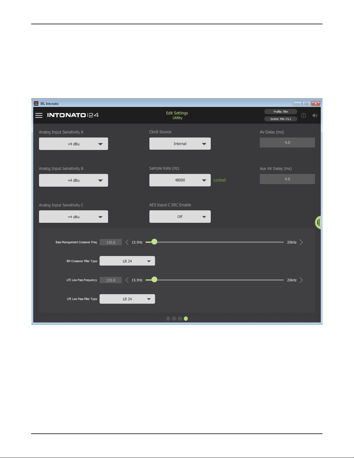
Application Examples
5.1 Full-Range Application Notes – Utility Conguration:
• The screenshot below shows the Utility screen for this application. The bass management
crossover frequency and LFE low-pass filter frequency can be fine-tuned from this screen. Delays
for the speaker system and talent headphones (to compensate for video display latency and
restore “lip synchronization”) and additional settings can also be configured from here.
• For more information on the fields shown in this screen, see
page 21
.
“Configuring Utility Settings” on
Page 56
Utility Screen
INTONATO | 24 Operation Manual
Page 59

Application Examples
5.1 Full-Range Application Notes – Scene Conguration:
• The screenshot below shows the Scene Builder screen for this
application, where scenes are created. In this application, scenes
are used to select the Blu-ray™/DVD player source for reference and
select the stereo or mono nearfield speakers for monitoring.
• Downmixing options are customizable to suit the application, allowing
the 5.1 signal to be downmixed to the stereo or mono reference
speakers, or the 5.1 speaker system to play back other downmixed
formats.
• For more information on the Scene Builder screen, see
Scenes” on page 36
.
“Creating
Scene Builder Screen
INTONATO | 24 Operation Manual
Page 57
Page 60

Application Examples
5.1 Full-Range Application Notes – User Master Control:
• The screenshot below shows the first user control screen for this application. From this screen,
the engineer can mute and solo individual speakers, turn bass management on or off, and control
master volume, mute, and dim. Enabling the Talkback button allows the engineer to communicate
with the talent during recording sessions.
• The Reference Level readout can be pre-calibrated to display the SPL of the monitor system.
• The inputs and outputs are color-coded as programmed from the Input and Output Configuration
screens.
• For more information on this control screen, see
“User Control – Master Controls” on page 40.
Page 58
Control Screen 1
INTONATO | 24 Operation Manual
Page 61

Application Examples
5.1 Full-Range Application Notes – User Scene Selection:
• The screenshot below shows the second user control screen for this application. From here,
the engineer can recall scenes that select sources or speaker systems for monitoring, or select
alternate downmixing options.
Control Screen 2
INTONATO | 24 Operation Manual
Page 59
Page 62

Application Examples
7.2 Bi-Amplied Application
TB (Talkback)
Mic
From
SourcesToSpeaker Amps
1. Mix Lf
2. Mix Rf
3. Mix C
4. Mix LFE
5. Mix Ls
6. Mix Rs
7. Mix LsB
8. Mix RsB
IP: 169.254.30.21
Events:
HQ: 2:6:801B SYSTEM BOOT
1. Lf High
2. Lf Low
3. Rf High
4. Rf Low
5. C High
6. C Low
7. Ls High
8. Ls Low
From
Sources
1. Blu-ray Lf
2. Blu-ray Rf
3. Blu-ray C
4. Blu-ray LFE
5. Blu-ray Ls
6. Blu-ray Rs
7. Not Used
8. Not Used
Speaker Amps
1. Rs High
2. Rs Low
3. LsB High
4. LsB Low
5. RsB High
6. RsB Low
7. L High
8. L Low
AUDIO SYSTEM
Lf SW 1 Rf
C
SW 2
To
To
Speaker Amps
1. R High
2. R Low
3. Not Used
4. Not Used
5. SW 1
6. SW 2
7. Aux L
8. Aux R
Talent
Headphones
Video Screen
Nearfield Monitors
Stereo
Downmixed Aux L/R + TB Mic
L R
Mixer/DAW
Rs
Ls
SPEAKER LEGEND
Reference Blu-ray/DVD Player
OPEN /
CLOSE
SKIPSKIP
PLAY / PAUSE
SEARCH
SEARCH
STOP
LsB
RsB
L = Left
R = Right
Lf = Left Front
Rf = Right Front
C = Center
SW = Subwoofer
Ls = Left Surround
Rs = Right Surround
LsB = Left Surround Back
RsB = Right Surround Back
Page 60
INTONATO | 24 Operation Manual
Page 63

Application Examples
7.2 Bi-Amplied Application Notes – Speaker Layout Conguration:
• Speaker layout 6 has been selected for this application. This provides up to 10 bi-amplified
outputs and 2 subwoofer outputs. The 2-channel aux output carries the fold-down mix and
talkback mic signal and is fed to the talent’s headphone amplifier.
• Two monitor systems are used: the main 7.2 speakers and the nearfield stereo speakers. All
satellite speakers are bi-amped.
Speaker Layout Selection Screen
INTONATO | 24 Operation Manual
Page 61
Page 64

Application Examples
7.2 Bi-Amplied Application Notes – Input Conguration:
• The screenshot below shows the Input Configuration screen for this application. From this screen,
physical inputs are assigned, input group assignments are made (to color-code input channels),
inputs are named, input LFE channels are designated, and input trims are calibrated if required.
NOTE: When the talkback mic is configured, it will be routed to input channel 24.
• For more information on the fields shown in this screen, see
“Configuring Inputs” on page 17.
Page 62
Input Configuration Screen
INTONATO | 24 Operation Manual
Page 65

Application Examples
7.2 Bi-Amplied Application Notes – Output Conguration:
• The screenshot below shows the Output Configuration screen for this application. From this
screen, speaker group assignments are made (to color-code the output channels), outputs are
named, speaker tunings are selected (if available), outputs are assigned for bass management,
and outputs are assigned to be controlled by the master volume, mute, and dim controls.
• The downmixed surround mix and talkback mic input are routed to the aux outputs on Analog
Output C7 and C8 (channels 23 and 24) and are sent to a headphone amplifier for monitoring by
the talent during voiceover/ADR recording sessions.
• For more information on the fields shown in this screen, see
“Configuring Outputs” on page 19.
Output Configuration Screen
INTONATO | 24 Operation Manual
Page 63
Page 66

Application Examples
7.2 Bi-Amplied Application Notes – Utility Conguration:
• The screenshot below shows the Utility screen for this application. The bass management
crossover frequency and LFE low-pass filter frequency can be fine-tuned from this screen. Delays
for the speaker system and talent headphones (to compensate for video display latency and
restore “lip synchronization”) and additional settings can also be configured from here.
• For more information on the fields shown in this screen, see
page 21
.
“Configuring Utility Settings” on
Page 64
Utility Screen
INTONATO | 24 Operation Manual
Page 67

Application Examples
7.2 Bi-Amplied Application Notes – Scene Conguration:
• The screenshot below shows the Scene Builder screen for this
application, where scenes are created. In this application, scenes are
used to select the Blu-ray/DVD player source for reference and select
the stereo nearfield speakers for monitoring.
• Downmixing options are customizable to suit the application, allowing
the 7.1 signal to be downmixed to the stereo reference speakers, or
the 7.2 speaker system to play back other downmixed formats (e.g.,
5.1, stereo, or mono).
• For more information on the Scene Builder screen, see
Scenes” on page 36
.
“Creating
Scene Builder Screen
INTONATO | 24 Operation Manual
Page 65
Page 68

Application Examples
7.2 Bi-Amplied Application Notes – User Master Control:
• The screenshot below shows the first user control screen for this application. From this screen,
the engineer can mute and solo individual speakers, turn bass management on or off, and control
master volume, mute, and dim. Enabling the Talkback button allows the engineer to communicate
with the talent during recording sessions.
• The Reference Level readout can be pre-calibrated to display the SPL of the monitor system.
• The inputs and outputs are color-coded as programmed from the Input and Output Configuration
screens.
• For more information on this control screen, see
“User Control – Master Controls” on page 40.
Page 66
Control Screen 1
INTONATO | 24 Operation Manual
Page 69

Application Examples
7.2 Bi-Amplied Application Notes – User Scene Selection:
• The screenshot below shows the second user control screen for this application. From here,
the engineer can recall scenes that select sources or speaker systems for monitoring, or select
alternate downmixing options.
Control Screen 2
INTONATO | 24 Operation Manual
Page 67
Page 70

Application Examples
Dolby Atmos Application
From
Sources
1. Mix Lf
2. Mix Rf
3. Mix C
4. Mix LFE
5. Mix Ls
6. Mix Rs
7. Mix LsB
8. Mix RsB
IP: 169.254.30.21
Events:
HQ: 2:6:801B SYSTEM BOOT
To
Speaker Amps
1. Lf
2. Rf
3. C
4. Ls
5. Rs
6. LsB
7. RsB
8. LsS
1. Mix LsS
2. Mix RsS
3. Mix Lh 1
4. Mix Rh 1
5. Mix Lh 2
6. Mix Rh 2
7. Blu-ray Lf
8. Blu-ray Rf
AUDIO SYSTEM
From
Sources
To
Speaker Amps
1. RsS
2. Lh 1
3. Rh 1
4. Lh 2
5. Rh 2
6. Not Used
7. Not Used
8. Not Used
From
Sources
1. Blu-ray C
2. Blu-ray LFE
3. Blu-ray Ls
4. Blu-ray Rs
5. Not Used
6. Not Used
7. Not Used
8. Not Used
To
Speaker Amps
1. Not Used
2. Not Used
3. Not Used
4. Not Used
5. SW 1
6. SW 2
7. SW 3
8. SW 4
LsS
Ls
Lf
SW 3
SW 1 Rf
C SW 2
Video Screen
Lh 1
Rh 1
Mixer/DAW
Lh 2
Rh 2
Reference Blu-ray/DVD Player
OPEN /
CLOSE
SKIPSKIP
PLAY / PAUSE
SEARCH
SEARCH
STOP
LsB
RsB
SW 4
RsS Rs
SPEAKER LEGEND
Lf = Left Front
Rf = Right Front
C = Center
SW = Subwoofer
Ls = Left Surround
Rs = Right Surround
LsB = Left Surround Back
RsB = Right Surround Back
LsS = Left Surround Side
RsS = Right Surround Side
Lh = Left Height
Rh = Right Height
Page 68
INTONATO | 24 Operation Manual
Page 71

Application Examples
Dolby Atmos Application Notes – Speaker Layout Conguration:
• Speaker layout 1 has been selected for this application. This provides up to 20 full-range outputs
and 4 subwoofer outputs.
Speaker Layout Selection Screen
INTONATO | 24 Operation Manual
Page 69
Page 72

Application Examples
Dolby Atmos Application Notes – Input Conguration:
• The screenshot below shows the Input Configuration screen for this application. From this screen,
physical inputs are assigned, input group assignments are made (to color-code input channels),
inputs are named, input LFE channels are designated, and input trims are calibrated if required.
• For more information on the fields shown in this screen, see
“Configuring Inputs” on page 17.
Page 70
Input Configuration Screen
INTONATO | 24 Operation Manual
Page 73

Application Examples
Dolby Atmos Application Notes – Output Conguration:
• The screenshot below shows the Output Configuration screen for this application. From this
screen, speaker group assignments are made (to color-code the output channels), outputs are
named, speaker tunings are selected (if available), outputs are assigned for bass management,
and outputs are assigned to be controlled by the master volume, mute, and dim controls.
• For more information on the fields shown in this screen, see
“Configuring Outputs” on page 19.
Output Configuration Screen
INTONATO | 24 Operation Manual
Page 71
Page 74

Application Examples
Dolby Atmos Application Notes – Utility Conguration:
• The screenshot below shows the Utility screen for this application. The bass management
crossover frequency and LFE low-pass filter frequency can be fine-tuned from this screen. Delays
for the speaker system and talent headphones (to compensate for video display latency and
restore “lip synchronization”) and additional settings can also be configured from here.
• For more information on the fields shown in this screen, see
page 21
.
“Configuring Utility Settings” on
Page 72
Utility Screen
INTONATO | 24 Operation Manual
Page 75

Dolby Atmos Application Notes – Scene Conguration:
• The screenshot below shows the Scene Builder screen for this
application, where scenes are created. In this application, scenes are
used to select the Blu-ray/DVD player source for reference.
• Downmixing options are customizable to suit the application. For
example, 5.1, 7.1, stereo, and mono fold-down mixes can all be preprogrammed and recalled via scenes.
Application Examples
• For more information on the Scene Builder screen, see
Scenes” on page 36
.
“Creating
Scene Builder Screen
INTONATO | 24 Operation Manual
Page 73
Page 76

Application Examples
Dolby Atmos Application Notes – User Master Control:
• The screenshot below shows the first user control screen for this application. From this screen,
the engineer can mute and solo individual speakers, turn bass management on or off, and control
master volume, mute, and dim.
• The Reference Level readout can be pre-calibrated to display the SPL of the monitor system.
• The inputs and outputs are color-coded as programmed from the Input and Output Configuration
screens.
• For more information on this control screen, see
“User Control – Master Controls” on page 40.
Page 74
Control Screen 1
INTONATO | 24 Operation Manual
Page 77

Application Examples
Dolby Atmos Application Notes – User Scene Selection:
• The screenshot below shows the second user control screen for this application. From here,
the engineer can recall scenes that select sources or speaker systems for monitoring, or select
alternate downmixing options.
Control Screen 2
INTONATO | 24 Operation Manual
Page 75
Page 78

Conguring the Clock Source
Conguring the Clock Source
The Intonato 24 can be clocked via the internal crystal oscillator, AES input, Word Clock input, or BLU
link bus.
To use BLU link, a 48 or 96 kHz sample rate must be used. In order for BLU link to be used
simultaneously with AES Input A and B, the Intonato 24 and AES source device must be synchronized
—via word clock or AES—at a 48 or 96 kHz sample rate and within a maximum tolerance of ±50
ppm.
Built-in sample rate conversion (SRC) can be applied to AES Input C. This allows other digital devices,
which are not slaved via a house clock, to be connected digitally to the Intonato 24. SRC can also
be used when combining BLU link and AES input signals operating at different sample rates. For
information on enabling/disabling SRC, see
The following table shows the Intonato 24’s clock configurations and the available inputs and outputs
for each.
“AES Input C SRC Enable” on page 22.
Intonato 24
Clock Source
Internal 44.1 kHz / 88.2 kHz No N/A
Internal 48 kHz / 96 kHz Yes
AES
(Input A Ch. 1)
AES
(Input A Ch. 1)
Word Clock
Word Clock
Sample Rate
44.1 kHz / 88.2 kHz No N/A
48 kHz / 96 kHz Yes
44.1 kHz / 88.2 kHz
(±50 PPM Max)
48 kHz / 96 kHz
(±50 PPM Max)
Can BLU link
I/O Be Used?
(Intonato 24 or another device on
the BLU link bus can be master)
(Intonato 24 must be master for
No N/A
Yes
(Intonato 24 must be master for
Intonato 24 is
BLU link Master
Optional
Yes
the BLU link bus
Yes
the BLU link bus)
Available Inputs
Analog
AES C (SRC On)
Analog
AES C (SRC On)
BLU link
Analog
AES A, B
AES C (SRC Optional)
Analog
AES A, B
AES C (SRC Optional)
BLU link
Analog
AES A, B,
AES C (SRC Optional)
Analog
AES A, B
AES C (SRC Optional)
BLU link
NOTE: When using BLU link, the Intonato 24 will need to be the BLU link master in most cases. For
information on BLU link mastership, see
“BLU link Mastership” on page 81.
The following sections illustrate the clocking configurations listed above and provide more information
on how the Intonato 24 would be configured for each.
Page 76
INTONATO | 24 Operation Manual
Page 79

Conguring the Clock Source
Clocking via the Internal Clock
When using only the analog input connections, the Internal clock source setting should be selected.
Note that AES Input A and B are not available in this configuration, however, AES Input C can still be
used as long as SRC is enabled. BLU link I/O is only available in this configuration if using a 48 or 96
kHz internal sample rate. Up to 24 input channels can be assigned.
Analog
Sources 1-8
IP: 169.254.30.21
Events:
HQ: 2:6:801B SYSTEM BOOT
Speaker
Monitors 1-8
Analog
Sources 9-16
Speaker
Monitors 9-16
Analog
Sources 17-24
Speaker
Monitors 17-24
Digital
NOTE: AES Input A and B are inoperable when
clocking via the internal clock or BLU link.
Sources
(SRC Enabled)
Intonato 24 Settings
Clock Source: Internal
Sample Rate: 44.1 kHz / 48 kHz / 88.2 kHz / 96 kHz
SRC: Enable if using AES Input C
INTONATO | 24 Operation Manual
BLU link
Device
(48 or 96 kHz Clock Only)
Optional
Page 77
Page 80

Conguring the Clock Source
Clocking via AES
When using the AES Input A and B connections without a house clock, the AES clock source setting
should be selected—the clock will be derived from the signal connected to AES Input A, channel 1.
Note that the analog inputs can still be used in this configuration if required. If using digital devices
which operate using a clock that differs from that connected to AES Input A and B, such devices can
be connected to AES Input C as long as the SRC feature is enabled. BLU link I/O is only available in
this configuration when using an AES clock operating at a 48 or 96 kHz sample rate. Up to 24 input
channels can be assigned.
Analog
Sources 1-8
IP: 169.254.30.21
Events:
HQ: 2:6:801B SYSTEM BOOT
Speaker
Monitors 1-8
Analog
Sources 9-16
Speaker
Monitors 9-16
Analog
Sources 17-24
Speaker
Monitors 17-24
Digital
Sources
Digital
Sources
Digital
Sources
(SRC Optional)
BLU link
Device
(48 or 96 kHz Clock Only)
Optional
NOTE: When using BLU link, the digital sources connected to AES Input A and B must be clocked
at a 48 or 96 kHz sample rate.
Intonato 24 Settings
Clock Source: AES (Input A, Channel 1)
Sample Rate: N/A, derived from AES signal
SRC (Optional): Enable if using AES Input C with different digital clocks
WARNING: To prevent unwanted noise through the speaker system, always mute the Intonato 24
outputs before changing the sample rate on the AES device that is providing the clock.
Page 78
INTONATO | 24 Operation Manual
Page 81

Conguring the Clock Source
Clocking via Word Clock
When using the AES inputs along with a house clock, Word Clock should be selected for the clock
source setting. Note that the analog inputs can still be used in this configuration if required. If using
digital devices which operate using a clock that differs from that connected to AES Input A and B,
such devices can be connected to AES Input C as long as the SRC feature is enabled. BLU link I/O is
only available in this configuration when using a house clock operating at a 48 or 96 kHz sample rate.
Up to 24 input channels can be assigned.
Analog
Sources 1-8
IP: 169.254.30.21
Events:
HQ: 2:6:801B SYSTEM BOOT
Speaker
Monitors 1-8
Analog
Sources 9-16
Speaker
Monitors 9-16
Analog
Sources 17-24
Speaker
Monitors 17-24
Digital
Sources
(Synced via House Clock)
Digital
Sources
(Synced via House Clock)
Digital
Sources
(SRC Optional)
BLU link
Device
(48 or 96 kHz Clock Only)
House
Clock
Optional
NOTE: When using BLU link, the digital sources connected to AES Input A and B must be clocked
at a 48 or 96 kHz sample rate from the house clock.
Intonato 24 Settings
Clock Source: Word Clock
Sample Rate: N/A, derived from Word Clock input
SRC (Optional): Enable if using AES Input C with different digital clocks
WARNING: To prevent unwanted noise through the speaker system, always mute the Intonato 24
outputs before changing the sample rate on the master word clock device.
INTONATO | 24 Operation Manual
Page 79
Page 82

Using BLU link
Using BLU link
BLU link is a proprietary, point-to-point digital audio bus found on many HARMAN products. It carries
256 channels of audio at 48 kHz or 128 channels at 96 kHz, both at 24 bits. The physical connections
are made with Cat5e or higher Ethernet cables.
BLU link Specications
• Based on Gigabit Ethernet technology
• Up to 100m over Cat5e cable between each point (>100m using fiber converters)
• 256 channels at 48 kHz, 128 channels at 96 kHz
• 24-bit audio resolution
• Bus-like architecture—audio transmitted on a channel is available at all other devices on the bus
• Wired in a loop for redundancy—recovers from a single cable break
• Up to 60 BLU link nodes (devices) can exist in a single BLU link system
Making BLU link Connections
On the rear panel of BLU link devices there are two BLU link ports: a BLU link input port and a BLU
link output port. Devices are connected together by wiring the output port of the first device to the
input port of the next, then repeating for each BLU link device on the bus.
NOTE: Only connect BLU link ports to other BLU link ports. Connecting BLU link ports to network
peripherals, such as an Ethernet switch or router, will not work.
See
“Configuring Inputs” on page 17 for information on assigning BLU link input channels.
“Configuring BLU link Outputs” on page 23 for information on assigning BLU link output
See
channels.
Page 80
INTONATO | 24 Operation Manual
Page 83

Using BLU link
BLU link Mastership
BLU link requires one device to provide the master clock for all other devices on the bus. This is
accomplished using priorities. Each connected BLU link device is given a “priority” value between
0 and 255, with 255 being the highest. The BLU link protocol auto-negotiates with all connected
devices to determine which device has the highest priority, and the device that wins becomes the
master clock for the BLU link bus.
In the Intonato 24, the BLU link priority setting is fixed at 128 when the unit is slaved via the internal
crystal oscillator or AES. When slaved via word clock, the priority setting is increased to 254 to ensure
the Intonato 24 is the BLU link master and that AES and BLU link can be used simultaneously. This
will force the Intonato 24 to provide master clock for the BLU link bus in most cases. If an application
requires that another BLU link device on the bus be the BLU link master, simply set its priority setting
to 255.
NOTE: The BLU link sample rate for all devices on a BLU link bus must be configured to match. See
“Configuring Utility Settings” on page 21 for information on changing the Intonato 24’s sample
rate setting.
BLU link Fault Tolerance
When the last BLU link device in a system is connected back to the first, the BLU link bus is capable
of a degree of fault tolerance since each device receives the same audio from two other devices. If
a single cable connection is broken, the devices that are no longer connected will detect the cable
break: one device will detect that its BLU link IN port is disconnected and the other will detect that its
OUT port is disconnected. The devices will then re-route the audio so that it can again pass through
the bus.
NOTE: When a cable connection is broken, the audio will take longer to reach its destination. This
added latency is not compensated for in any way, but is a side effect of the way the fault tolerance
system functions.
INTONATO | 24 Operation Manual
Page 81
Page 84

Using BLU link
BLU link Port LED Indicators
Each BLU link port has LEDs that indicate the following:
Both Yellow LEDs On
This indicates the device is the BLU link master, and it is providing
the clock for all other devices on the BLU link bus.
The green LEDs light to indicate the port has established a link with
the BLU link bus.
One Yellow LED On
This indicates the device is slaved to the BLU link clock received
from the connected device.
The green LEDs light to indicate the port has established a link with
the BLU link bus.
No Yellow LEDs On
This indicates the device is not receiving BLU link clock and will not
pass BLU link audio. This either indicates the IN and OUT ports are
swapped (an OUT port is connected to an OUT port and an IN port
is connected to an IN port), or there is a mismatch between the
BLU link sample rates of the Intonato 24 and the connected BLU
link device(s). See
information on changing the sample rate setting.
The green LEDs light to indicate the port has established a link with
the BLU link bus.
“Configuring Utility Settings” on page 21 for
WARNING: Only connect to BLU link systems that remain inside the building.
Page 82
INTONATO | 24 Operation Manual
Page 85

Using BLU link
Conguring Crown DCi Network Series Ampliers
This section of the manual describes how to configure the Intonato 24 and DCi Network Series
amplifiers for BLU link operation.
Follow these steps to use BLU link with the Intonato 24 and DCi Series amplifiers:
1. Using the Intonato control app, select BLU link Output from the Main User Menu. Now configure
and enable the Intonato 24 BLU link outputs. Refer back to this screen for reference when
assigning BLU link channels to the DCi amplifier inputs.
2. Select the tab on the right of the screen to view the master controls. Set the Master Volume
control to around -20 dB. This will prevent sudden loud signals from playing through the system
once BLU link audio is established.
INTONATO | 24 Operation Manual
Page 83
Page 86

Using BLU link
3. Select Edit Settings from the Main User Menu and navigate to the fourth screen by swiping or
selecting the fourth bubble at the bottom. Verify the sample rate is correctly set for the application.
Note that either 48 or 96 kHz must be selected to use BLU link. Take note of this setting so the
DCi amplifiers can be set to match in a later step.
4. Download and install HiQnet Audio Architect™.
5. Launch Audio Architect.
6. To edit DCi settings in real time, the DCi amplifiers must be discovered on the network and Audio
Architect must enter “Run Venue” mode (sometimes referred to as “going online”). The prompt
below should appear once Audio Architect initializes. To automatically go online with discovered
HiQnet devices, check the
the
Automatically navigate to Run Venue mode checkbox. Now click the Close button.
NOTE: If the above prompt does not appear, the DCi amplifiers or the Audio Architect
application may be incorrectly configured for the network. Ensure Audio Architect’s Application
Options are correctly configured for your network interface card (NIC). See the DCi amplifier
manual for further information about adding HiQnet devices to the Venue and using Run Venue
mode. Further information is also available in Audio Architect’s help file. If you’re having problems
connecting to the DCi amp over the network, see
DCi amplifier manual.
Add discovered devices to the Venue automatically checkbox and
“Networking” on page 89 or refer to the
Page 84
INTONATO | 24 Operation Manual
Page 87

Using BLU link
7. Double-click the DCi icon in the Room window to open the DCi Control panel.
8. Open the DCi Input Configuration panel by double-clicking the first Input icon, then click the Input
Configuration
button. Now click the Audio Routing button.
9. From the BLU Link Input Channel Assignment window, click and drag the BLU link output
channels to be assigned to the DCi BLU link input slots (e.g., Network Input A, Network Input B,
etc.). Refer to the assignments made in step 1 for reference. When done, click the
OK button.
INTONATO | 24 Operation Manual
Page 85
Page 88

Using BLU link
10. BLU link audio may now be passing through the DCi amplifier. If it isn’t, click the Advanced
Settings
matches the setting noted in step 3. When done, close the Advanced Settings and Input
Configuration panels.
button from the DCi Input Configuration panel. Ensure the BLU link sample rate setting
11. The DCi amplifiers come preconfigured with the respective analog inputs configured as “high-
priority” inputs and the BLU link inputs configured as “medium-priority” inputs. Although this
may work fine, if the application doesn’t actually require prioritized inputs, it’s recommended to
configure the BLU link inputs as “high-priority” inputs. From the Source Routing panel, select the
desired BLU link input slot for the DCi input channel under the
Ensure the
each input channel, accessing each by clicking the respective
panel.
Medium Source and Low Source inputs are now defaulted to “None”. Repeat for
High Source dropdown menu.
Input icon from the DCi Control
12. BLU link audio should be passing through the amplifier as expected. If it isn’t, go back through the
steps and ensure the device sample rate settings match, BLU link channels are correctly assigned,
and that Audio Architect is running in “Run Venue” mode. Adjust system volume using the Intonato
24 Master Volume control.
Page 86
INTONATO | 24 Operation Manual
Page 89

Speaker Tunings
Speaker Tunings
When a speaker tuning is selected for a speaker model, the Intonato 24 loads the correct tuning
parameters to optimize the speaker for use in the system. The system can then be further optimized
for the production environment by using the Intonato 24’s easy-to-use auto-calibration feature.
Speaker tunings are comprised of the following parameters:
•
Crossover, Level Trim, and Delay (Bi-amplified Speakers Only)
Speaker tunings for bi-amplified speaker models use crossover filters to split the signal between
the low-frequency and high-frequency driver components. A level trim is then used to match driver
component levels. Lastly, a delay is used on the high-frequency driver to time-align it to the lowfrequency driver.
•
EQ
Full-range, bi-amp, and sub speaker tunings use a 14-band parametric EQ to flatten the frequency
response of the speaker.
•
dbx® OverEasy™ Limiter (with Sidechain)
Full-range, bi-amp, and sub speaker tunings use a dbx OverEasy (soft-knee) limiter for speaker
protection. A 3-band sidechain EQ is used to tailor the limiter’s gain reduction characteristics to
fine-tune speaker protection. Note that the limiter threshold must be set manually to engage the
limiter for speaker protection. See
“Limiter Threshold” on page 29 for more information.
The Intonato 24 contains factory preset tunings for the following speakers:
•
Other
Select this option when a tuning for the
speaker model is not listed.
•
LSR705i
Full-range tuning for the JBL LSR705i
speaker.
•
LSR708i
Full-range tuning for the JBL LSR708i
speaker.
•
LSR705i Bi Amp
Bi-amped tuning for the JBL LSR705i
speaker.
•
LSR708i Bi Amp
Bi-amped tuning for the JBL LSR708i
speaker.
•
M2 Bi Amp
Bi-amped tuning for the JBL M2 speaker.
•
Other
Select this option when a tuning for the
subwoofer model is not listed.
•
S2S–EX
Tuning for the JBL S2S–EX sub.
• Sub18
Tuning for the JBL Sub18 sub.
• 4645C
Tuning for the JBL 4645C sub.
• M2 VLF Protect
Bi-amped tuning for the JBL M2 speaker
with high-pass filter for low-frequency driver
protection.
INTONATO | 24 Operation Manual
Page 87
Page 90

The Intonato DC Desktop Controller
The Intonato DC Desktop Controller
The optional Intonato DC desktop controller is available for dedicated control of the Intonato 24.
Contact your local JBL Professional dealer or visit www.jblpro.com/intonato24 for more information.
Page 88
INTONATO | 24 Operation Manual
Page 91

Networking
Networking
This section of the manual provides basic information on network settings, network security, and
network troubleshooting. It also covers the HiQnet NetSetter application, which is used to assign a
static IP address to the Intonato 24 and resolve HiQnet setting conflicts.
Networking Overview
Below is a brief description of the most common network settings.
IP Address
•
An IP address is an identifier for a computer or device on a TCP/IP network. Each device in a
network has its own IP address to identify it (e.g., 126.126.17.42). Networks using the TCP/IP
protocol route messages based on the IP address of the destination. An IP address is made of
four numbers separated by periods. Each number can be 0 (zero) to 255. The last number should
not be a 0 (zero) or 255. For example, 126.126.17.1 could be an IP address. 126.126.17.0 would
not be a valid IP address.
A TCP/IP or IP address has two parts: the Network ID and the Host ID. The Network ID identifies
the network, and the Host ID identifies either the subnet and device, or just the device if there is no
subnet. The subnet mask is a code that indicates which part of the TCP/IP address is the Network
ID and which part is the Host ID. In subnet-mask code, 255 identifies the part of the address
that is the Network ID. For example, suppose the IP address of a device is 192.168.xx.yy and
the subnet mask is 255.255.x.y. That means, “192.168” is the Network ID. The remaining set of
numbers (xx.yy) is the Host ID. If the network stands alone (it is not part of a larger network) then
the Host ID identifies each device in the network. If the network is part of a venue’s larger network,
the network is actually a sub-network or subnet.
•
Subnet
A subnet is a small network within a larger network. For example, a TCP/IP network in a single
area might be a subnet of a venue’s larger network, which could include computers throughout
the building. Or, a network might be divided into multiple subnets. For example, a large installation
may have one subnet per rack or room.
•
DHCP (Dynamic Host Configuration Protocol)
DHCP is a protocol for automatically assigning IP addresses to devices on a network. With
dynamic (DHCP) addressing, a device might have a different IP address every time it connects to
the network. DHCP relies on a DHCP server to assign and manage IP addresses. Most network
routers come equipped with a built-in DHCP server.
•
Gateway
A gateway is used to connect two different networks and allow packets to be passed between
them. In a typical home network, the router provides the “gateway” connection between the
local area network (LAN) and Internet (WAN) so they can communicate. A gateway can translate
between one network system or protocol and another.
INTONATO | 24 Operation Manual
Page 89
Page 92

Networking
Network Security
Careful planning should be made before placing an Intonato 24 on a network that is accessible by the
public—for example, direct access to the device using an unsecured/weakly secured wireless network
or a network jack in a public area.
It is highly recommended that the Intonato 24 be placed on a protected, isolated network that
does not have any connection to the public. This prevents unauthorized users from reconfiguring
or controlling the device. Most routers have built-in functions which help protect the network from
unauthorized users, such as MAC address filtering, encryption, and disabling the SSID broadcast.
Check the documentation for the network router for information on configuring available security
options.
Network Troubleshooting
The Intonato 24 must be connected to a DHCP-enabled network for initial configuration and control.
Connecting the Intonato 24 to the network should be as easy as plugging it into the switch/router and
waiting for it to get assigned an IP address. However, some additional configuration will be required
if using static IP addressing and/or network security features. If a network connection cannot be
established with the Intonato 24, try following these steps to resolve the issue:
1. Ensure Networked Devices are Powered On
Ensure the control device, all network peripherals (switches, routers, bridges, etc.), and the
Intonato 24 are powered on and wait a few minutes to allow all devices to boot and get assigned
IP addresses. Look at the Intonato 24’s back-panel LCD and ensure it has an IP address. If it
reads “0.0.0.0”, or a network connection still cannot be established, go to the next step.
2. Check Network Activity LEDs, Cables, and Connections
Ensure the yellow and green LEDs are lighting on the Intonato 24’s Ethernet
port. Also, ensure the port activity/link LEDs are lighting on the router (and
switch, if applicable). If using a wired connection from a computer, ensure
the Ethernet port LEDs light on the computer’s Ethernet port. Note that the
yellow LED may only flash occasionally; this is normal.
If any of these activity/link LEDs are not lighting, try disconnecting then
reconnecting the corresponding Ethernet cable. If the LEDs still don’t light,
try swapping out the connected Ethernet cable for another, known-working
cable. Also, make sure the correct type of Ethernet cable is used. If using a crossover cable, it
may be causing the problem (depending on the capabilities of the router/switch) and the cable
may need to be replaced with a straight-through Ethernet cable.
If an Ethernet port’s LEDs begin lighting after reconnecting or swapping out cables, wait a few
minutes, check the Intonato 24’s back-panel LCD for an assigned IP address, then try
reconnecting with the JBL Intonato control app. If a network connection still cannot be
established, go to the next step.
Page 90
INTONATO | 24 Operation Manual
Page 93

Networking
3. Check IP Addresses and Network Settings
Ensure the control device’s network connection is configured for DHCP, and that it doesn’t have
a static IP or Auto-IP (169.254.xx.yy) address. Check the IP addresses of the router, control
device, and Intonato 24 and ensure they all have the same Network ID. Once all Network IDs are
confirmed to match, try reconnecting with the JBL Intonato control app.
If the Intonato 24’s IP address reads “0.0.0.0” when an Ethernet cable is connected, and the
Intonato 24’s Ethernet port LEDs are lighting, this indicates the DHCP server may not be assigning
the Intonato 24 an IP address. This could indicate a problem with the DHCP server settings in the
router. If the JBL Intonato control app still won’t connect, go to the next step.
4. Check Router/Switch Configuration Settings
Check the settings in the network router/switch (consult the documentation that came with the
network router/switch to see how to enter the utility used to configure it). Ensure the DHCP server
is enabled and that the DHCP address range is properly configured. Once the DHCP server has
been properly configured and enabled, wait a few minutes to see if the Intonato 24 has been
assigned an IP address.
If the DHCP server is properly configured and the Intonato 24 and control device have compatible
network settings but still won’t communicate, traffic is likely being prohibited by a software or
hardware firewall. If connecting using a router/switch that has an enabled hardware firewall, try
disabling the firewall and then relaunching the JBL Intonato control app. If this fixes the problem,
refer to the router/switch documentation on how to reconfigure the firewall to allow the JBL
Intonato control app, or ports 19272 and 3804 (TCP and UDP) and port 21 (FTP), to pass through
the firewall. If the control app still won’t connect, go to the next step.
5. Check Software Firewalls
If connecting using a Mac or Windows computer, check any enabled software firewalls in the
computer. Try disabling the firewall and then relaunching the JBL Intonato control app. If this fixes
the problem, refer to the firewall manufacturer’s documentation on how to reconfigure the firewall
to allow the JBL Intonato control app, or ports 19272 and 3804 (TCP and UDP) and port 21 (FTP),
to pass through the firewall.
INTONATO | 24 Operation Manual
Page 91
Page 94

Networking
Using HiQnet® NetSetter™
The Intonato 24 must be connected to a DHCP-enabled network to be assigned an IP address.
Once an IP address is assigned, the HiQnet NetSetter application can be used to manually configure
Intonato 24 network settings if required for the application.
Conguring the Network Using NetSetter
NetSetter is a Windows-compatible software tool that detects HiQnet devices on a network and
allows their network settings to be reconfigured in real time from one central location. Its function is
to configure a system of devices to interoperate correctly on the same network and resolve conflicts
quickly and easily.
NOTE: All HiQnet devices on the network must have a unique device ID (also known as a HiQnet
“node address” or “node ID”). If a device ID conflict occurs, edit one of the device ID addresses to
resolve the conflict.
The latest version of NetSetter can be downloaded from http://hiqnet.harmanpro.com/software/.
The top of the NetSetter window displays overall operational functions that are available. At the
bottom of the NetSetter window is an informational section that lists the number of discovered
devices and the IP address of the DHCP server. There is also information regarding the PC HiQnet
Address, IP Address, and Subnet Mask.
Follow these steps to configure the Intonato 24 with a static IP address:
Uncheck the DHCP/Auto-IP checkbox.
1.
2. Click in the IP Address field and enter the desired IP address.
3. Click in the Subnet Mask field and enter the desired subnet mask.
4. Click in the Default Gateway field and enter the gateway address.
5. Click the Apply Current Edits button to finalize the changes.
Follow these steps to configure the Intonato 24 back to use DHCP addressing:
Check the DHCP/Auto-IP checkbox.
1.
2. Click the Apply Current Edits button to finalize the changes.
3. Wait a couple minutes for the DHCP server to assign the Intonato 24 an IP address.
For more information on using NetSetter, click on the help icon in the upper right-hand corner of the
NetSetter window.
Page 92
INTONATO | 24 Operation Manual
Page 95

Signal Path Block Diagram
Input
Inputs
Inputs
Input
Input
Analog
BLU link
Signal Path Block Diagram
LEGEND
Top-Level Settings
Speaker Layout Selection
(App Menu: Speaker Layout)
System Calibration
(App Menu: System Calibration)
BLU link Output Router
(App Menu: BLU Link Output)
Reference Level User Calibration
(App Menu: Speaker Calibration->Signal Generator)
Profile Settings
Speaker Tuning
(App Menu: Edit Settings->Outputs)
AV Delay & Aux AV Delay
(App Menu: Edit Settings->Utility)
User EQ
(App Menu: Edit Settings->User EQ)
*Aux Tone EQ
(App Menu: Controls->Aux)
LFE Low-Pass Filter Frequency
(App Menu: Edit Settings->Utility)
Bass Mgmt. Xover Frequency
(App Menu: Edit Settings->Utility)
Input LFE Select
(App Menu: Edit Settings->Inputs)
Bass Mgmt. Select
(App Menu: Edit Settings->Outputs)
Input Router/Names/Groups
(App Menu: Edit Settings->Inputs)
Analog Input Sensitivity
(App Menu: Edit Settings->Utility)
*Bass Management On/Off
(App Menu: Controls)
SRC Enable
(App Menu: Edit Settings->Utility)
*Aux Level
(App Menu: Controls->Aux)
Input Trim
(App Menu: Edit Settings->Inputs)
BLU link Input Router
(App Menu Inputs: Edit Settings->Inputs)
Clock Source & Sample Rate
(App Menu Inputs: Edit Settings->Utility)
Scene Settings
Input & LFE Mix Levels
(App Menu: Scene Builder)
Persistent Settings
*Master Volume/Dim/Mute
(App Menu: Controls)
*Speaker Mute/Solo
(App Menu: Controls)
*Talkback Enable
(App Menu: Controls)
= End-user controllable via the app control screens.
*
Speaker Layout Selection/Channels
Layout Bi-Amp Full-Range Sub Aux
- 20 4 -
1
- 20 2 2
2
3 14 4 -
3
3 14 2 2
4
10 - 4 -
5
10 - 2 2
6
Speaker
Tuning
With Limiter
System
Calibration
12-Band PEQ
Time-Align Delay
Bi-Amp Channels
Output Level
AV Delay
Up to 170 ms
User EQ
8-Band PEQ
Bass Mgmt.
Input Mixer Input Mixer Input Mixer
App Reference
Level
ADC
Analog Input
Sensitivity
-10 dBV (15.8 dB Pad)
+4 dBu (-4 dB Pad)
+8 dBu
8
A
13 12 11 109 8 7 6 5 4 3 2 1
25 24 23 2221 20 19 18 17 16 1514
Analog Input
Sensitivity
-10 dBV (15.8 dB Pad)
+4 dBu (-4 dB Pad)
+8 dBu
8
B
13 12 11 109 8 7 6 5 4 3 2 1
25 24 23 2221 20 19 18 17 16 1514
Outputs
A
13 12 11 109 8 7 6 5 4 3 2 1
25 24 23 2221 20 19 18 17 16 1514
B
13 12 11 109 8 7 6 5 4 3 2 1
25 24 23 2221 20 19 18 17 16 1514
8 8
C
13 12 11 109 8 7 6 5 4 3 2 1
25 24 23 2221 20 19 18 17 16 1514
DACDACDAC
Front-Panel
Output LEDs
Clip
Signal
Enabled
Off
Speaker
With Limiter
Calibration
12-Band PEQ
Time-Align Delay
Polarity
HPF
24
App Input
Levels
24 8 8 8
Output Level
Full-Range Channels
AV Delay
Up to 170 ms
User EQ
8-Band PEQ
Bass Mgmt.
Front-Panel
Input LEDs
Clip
Signal
Enabled
Off
Tuning
System
Polarity
HPF
24
24
Clip
Signal
Enabled
Off
Input Matrix Router
72 In x 24 Out
Clip
Signal
Enabled
Off
Speaker
Tuning
With Limiter
System
Calibration
Sub Channels
12-Band PEQ
Time-Align Delay
Output Level
Polarity
AV Delay
Up to 170 ms
User EQ
8-Band PEQ
LPF
LFE
LPF
Bass Mgmt.
LFE Mixer BM Mixer
Input LFE
Bass Mgmt.
Select
Select
Clock Gen
Analog Input
Sensitivity
-10 dBV (15.8 dB Pad)
+4 dBu (-4 dB Pad)
+8 dBu
8 8 8 8
C
13 12 11 109 8 7 6 5 4 3 2 1
25 24 23 2221 20 19 18 17 16 1514
Mic Pre
+48V
AES Ch. 1 Clock
A
13 12 11 109 8 7 6 5 4 3 2 1
25 24 23 2221 20 19 18 17 16 1514
AES Receiver
B
13 12 11 109 8 7 6 5 4 3 2 1
25 24 23 2221 20 19 18 17 16 1514
Output
248
BLU link
Output Router
Stereo Aux Channel
Aux AV
Delay
Up to 170 ms
Aux Tone
3-Band EQ
24
Mic Input (Ch. 24)
24
SRC
BLU link
24 Channel
Input Router
256 @ 48 kHz
128 @ 96 kHz
C
13 12 11 109 8 7 6 5 4 3 2 1
25 24 23 2221 20 19 18 17 16 1514
Analog
Mic
INTONATO | 24 Operation Manual
Word Clock
AES
BLU link
Page 93
Page 96

Dimensions
(19.05mm)
(482.6mm)
Dimensions
0.75”
17.25”
(438.15mm)
13”
(330.2mm)
3.5”
(88.9mm)
19”
Page 94
INTONATO | 24 Operation Manual
Page 97

Specications
Specications
INPUTS
Total Simultaneous Inputs: 24 (selectable among the available 24 analog, 24 AES3, and 24 BLU link input
channels)
ANALOG INPUTS
Connectors: 3 female 25-pin D-Sub connectors
Type: Electronically balanced, RF filtered
Impedance: > 48 kΩ balanced, > 24 kΩ unbalanced
Input Sensitivity: Selectable in software per D-Sub connector: -10 dBV with 18 dB of headroom, +4
dBu with 20 dB of headroom, +8 dBu with 24 dB of headroom
Max Input Level: +28 dBu, ≤0.008% THD
CMRR: > 47 dB @ 1 kHz
Ground Lift: Switchable per D-Sub connector
AES3 DIGITAL INPUTS
Connectors: 3 female 25-pin D-Sub connectors
Type: Electronically balanced, transformer coupled RF filtered
Impedance: 110 Ω
Sample Rate Conversion: Selectable in software for AES Input C only
MIC INPUT
Connector: Female XLR
Type: Electronically balanced, RF filtered
Impedance: > 1.5 kΩ, balanced
CMRR: > 70 dB from 20 Hz to 20 kHz
Phantom Power: +48 VDC
Gain: 30 dB fixed
WORD CLOCK INPUT
Connector: BNC
Supported Sample Rates: 44.1 kHz, 48 kHz, 88.2 kHz, 96 kHz
Tolerance: ±50 ppm max
OUTPUTS
Total Simultaneous Outputs: 24 analog outputs (analog outputs can be mirrored to assignable BLU link output
channels)
ANALOG OUTPUTS
Connectors: 3 female 25-pin D-Sub connectors
Type: Electronically balanced, RF filtered
Impedance: 60 Ω balanced, 30 Ω unbalanced
Max Output Level: +24 dBu, balanced, ≤ .006% THD
A/D PERFORMANCE
A/D Converter: 24-bit
A/D Dynamic Range: 114 dB A-weighted
D/A PERFORMANCE
D/A Converter: 24-bit
D/A Dynamic Range: 115 dB A-weighted
INTONATO | 24 Operation Manual
Page 95
Page 98

Specications
BLU LINK AUDIO
Connectors: 2 x RJ45 connectors
Maximum Nodes: 60
Maximum Cable Length: 100m/328ft on Category 5e or higher cable between devices
Latency: 11/Fs [0.23ms@48k, 0.11ms@96k]
Pass Through Latency: 4/Fs [0.08ms@48k, 0.04ms@96k]
SIGNAL PROCESSING
User EQ: 8-band fully parametric EQ w/ selectable filter type for each band
Room EQ: 12-band fully parametric EQ w/ selectable filter type for each band
Bi-Amp Crossover: No speaker tuning selected: No Crossover is applied.
With speaker tuning selected: Varies to optimize speaker for tuning selection
LFE Low-Pass Filter: Variable, 16 Hz – 20 kHz
Bass Management Crossover: Variable, 16 Hz – 20 kHz
Speaker Output Delay: Up to 170 ms (applied per output channel for speaker time-of-arrival offset)
Lip Synchronization Delay: Up to 170 ms (globally applied to all output channels except aux outputs)
Aux Out Lip Synchronization Delay: Up to 170 ms (applied to aux output channels only)
Master Volume Control: -120 dB to 0 dB
Dim Control: -120 dB to 0 dB
SYSTEM PERFORMANCE
Internal Processing Wordlength: 32-bit floating point
Supported Sample Rates: 44.1 kHz, 48 kHz, 88.2 kHz, 96 kHz (32-192 kHz using sample rate conversion)
Dynamic Range: 114 dB A-weighted
112 dB unweighted 20Hz – 22kHz
THD+Noise: 0.007% typical at +4 dBu, 1 kHz, 0 dB input gain
Frequency Response: 20 Hz – 20 kHz, +0 /- 0.5 dB
Interchannel Crosstalk: < -70 dB
Latency: Analog input to analog output: 2.57 ms (48 kHz), 2.28 ms (96 kHz)
AES input to analog output: 2.31 ms (48 kHz), 2.15 ms (96 kHz)
BLU link input to analog output: 0.08ms (48 kHz), 0.04ms (96 kHz)
BLU link input to BLU link output: 0.08ms (48 kHz), 0.04ms (96 kHz)
Operating Temperature Range: 0º to 40º C (32º to 104º F)
POWER SUPPLY
Type: Universal switch-mode
Operating Voltage: 100-240 VAC, 50/60 Hz
Power Consumption: 85 Watts
PHYSICAL
Rack Height: 2U
Unit Weight: 14.30 lbs (6.49 kg)
Shipping Weight: 19.04 lbs. (8.64 kg)
Dimensions: 3.5” (H) x 13.75” (D) x 19.0” (W)
88.9mm (H) 349.25mm (D) x 482.6mm (W)
RECOMMENDED AUDIO BREAKOUT CABLES
DB25 Analog Input Hosa Technology®: DTF-803
DB25 Analog Output Hosa Technology®: DTM-803
DB25 AES Input Digidesign®: DigiSnake Cable (note that only AES input connections are used)
(DB25 – XLR MtF AES/EBU snake, DB25 to 4 XLRM (output) and 4 XLRF (input),
Model # MH097; P/N DB-XMtF-4-ROHS)
Specifications subject to change without notice.
Page 96
INTONATO | 24 Operation Manual
Page 99

Appendix
Fuse in circuit
Appendix
Replacing the Fuse
The power fuse is located in a drawer in the IEC power inlet on the back panel of the Intonato 24.
From the factory, there will be two fuses in this drawer. The fuse located in the rear drawer position is
the one currently being used in the circuit. The fuse located in the front drawer position is the provided
spare fuse.
Insert a small flat-head screwdriver
behind the tab and gently slide open.
USE ONLY WITH A 250V FUSE
WARNING: Replace with same type fuse only (T2.5A, L 250V).
Spare fuse
INTONATO | 24 Operation Manual
Page 97
Page 100

Appendix
D-Sub Connector Pinouts
The following diagrams show the pinouts for the D-Sub connectors. The analog and AES connectors
use the industry-standard TASCAM DB25 pinout.
Analog In/Out DB25 Pinout (Female)
AES In DB25 Pinout (Female)
NOTE: See “Specifications” on page 95 for information on recommended DB25 breakout cables.
Page 98
INTONATO | 24 Operation Manual
 Loading...