

Page 1
X +
0 +
Y
2
0
M
HZ
X + 0 + Y2 0MHZ”
X + 0 + Y
2
THANK YOU FOR CHOOSING JBL
For more than 50 years, JBL
has been involved in every
aspect of music and film
recording and reproduction,
from live performances to
the recordings you play in
your home, car or office.
We’re confident that the JBL
loudspeakers you have
chosen will provide every
note of enjoyment that you
expected – and that when
you think about purchasing
additional audio equipment
for your home, car or
office, you will once again
choose JBL.
Please take a moment to
complete the enclosed
profile card. It enables us to
keep you posted on our
latest advancements, and
helps us to better understand our customers
and build products that
meet their needs and
expectations.
JBL Consumer Products
DESIGN GOAL: Bring the thrill of live performance and movie sound to
the homeenvironment bycalling on JBL’s professional engineering leadership.
CROSSOVER NETWORK: THX®-Ultra Certified
WOOFER TYPE:
Aluminum cone with rubber surrounds
ENCLOSURE DESIGN: Sealed
PROFESSIONAL REFERENCE: Cinema Loudspeaker Series
OWNER’S GUIDE
PRODUCT LINE:
HT SERIES
MODEL
HTPS-400
NUMBER:
TWO UNITS MINIMUM
Page 2
2
1. Read these instructions.
2. Keep these instructions.
3. Heed all warnings.
4. Follow all instructions.
5. Do not use this apparatus near water.
6. Clean only with a dry cloth.
7. Do not block any ventilation openings.
Install in accordance with the
manufacturer’s instructions.
8. Do not install near any heat sources
such as radiators, heat registers, stoves
or other apparatus (including amplifiers)
that produce heat.
9. Do not defeat the safety purpose of
the polarized or grounding-type plug.
A polarized plug has two blades with
one wider than the other. A groundingtype plug has two blades and a third
grounding prong. The wide blade or the
third prong are provided for your safety.
If the provided plug does not fit into
your outlet, consult an electrician for
replacement of the obsolete outlet.
10. Protect the power cord from being
walked on or pinched, particularly at
plugs, convenience receptacles and the
point where they exit from the apparatus.
11. Only use attachments/accessories
specified by the manufacturer.
12. Use only with the cart,
stand, tripod, bracket or
table specified by the
manufacturer or sold
with the apparatus.
When a cart is used,
use caution when moving the
cart/apparatus combination to avoid
injury from tip-over.
13. Unplug this apparatus during lightning
storms or when unused for long periods
of time.
14. Refer all servicing to qualified service
personnel. Servicing is required when the
apparatus has been damaged in any way,
such as power-supply cord or plug is
damaged, liquid has been spilled or
objects have fallen into the apparatus,
the apparatus has been exposed to rain
or moisture, does not operate normally, or
has been dropped.
15. Do not use attachments not recommended by the product manufacturer, as
they may cause hazards.
16. This product should be operated only
from the type of power source indicated
on the marking label. If you are not sure
of the type of power supply to your home,
consult your product dealer or local
power company. For products intended to
operate from battery power, or other
sources, refer to the operating
instructions.
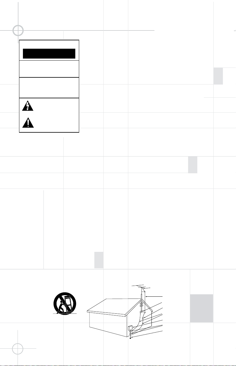
17. If an outside antenna or cable system
is connected to the product, be sure the
antenna or cable system is grounded so
as to provide some protection against
voltage surges and built-up static
charges. Article 810 of the National
Electrical Code, ANSI/NFPA 70, provides
information with regard to proper
grounding of the mast and supporting
structure, grounding of the lead-in wire
to an antenna discharge unit, size of
grounding conductors, location of
antenna-discharge unit, connection to
grounding electrodes, and requirements
for the grounding electrode. See Figure A.
18. An outside antenna system should not
be located in the vicinity of overhead
power lines or other electric light or
power circuits, or where it can fall into
such power lines or circuits. When
installing an outside antenna system,
extreme care should be taken to keep
from touching such power lines or circuits,
as contact with them might be fatal.
19. Do not overload wall outlets,
extension cords, or integral convenience
receptacles, as this can result in a risk of
fire or electric shock.
20. Never push objects of any kind into
this product through openings, as they
may touch dangerous voltage points or
short-out parts that could result in a fire
or electric shock. Never spill liquid of any
kind on the product.
21. Do not attempt to service this product
yourself, as opening or removing covers
may expose you to dangerous voltage or
other hazards. Refer all servicing to
qualified service personnel.
22. When replacement parts are required,
be sure the service technician has used
replacement parts specified by the
manufacturer or that have the same
characteristics as the original part.
Unauthorized substitutions may result in
fire, electric shock or other hazards.
23. Upon completion of any service or
repairs to this product, ask the service
technician to perform safety checks to
determine that the product is in proper
operating condition.
24. The product should be mounted to a
wall or ceiling only as recommended by
the manufacturer.
Figure A.
Example of Antenna
Grounding as per National
Electrical Code, ANSI/NFPA 70
READ THIS! Important Safety Precautions!
CAUTION
RISK OF ELECTRIC SHOCK
DO NOT OPEN
CAUTION: To reduce the risk of electric shock,
do not remove cover (or back).
No user-serviceable parts inside.
Refer servicing to qualified service personnel.
CAUTION: To prevent electric shock,
do not use this (polarized) plug with
an extension cord, receptacle or other outlet
unless the blades can be fully inserted to
prevent blade exposure.
The lightning flash with arrowhead symbol,
within an equilateral triangle, is intended to
alert the user to the presence of uninsulated
“dangerous voltage” within the product’s
enclosure that may be of sufficient magnitude to constitute
a risk of electric shock to persons.
The exclamation point within an equilateral
triangle is intended to alert the user to the
presence of important operating and
maintenance (servicing) instructions in the
literature accompanying the appliance.
Antenna Lead-In Wire
Ground Clamp
Antenna Discharge Unit (NEC Section 810-20)
Grounding Conductors (NEC Section 810-21)
Electric Service Equipment
Ground Clamps
Power Service Grounding Electrode System
(NEC Art 250, Part H)
Page 3
3
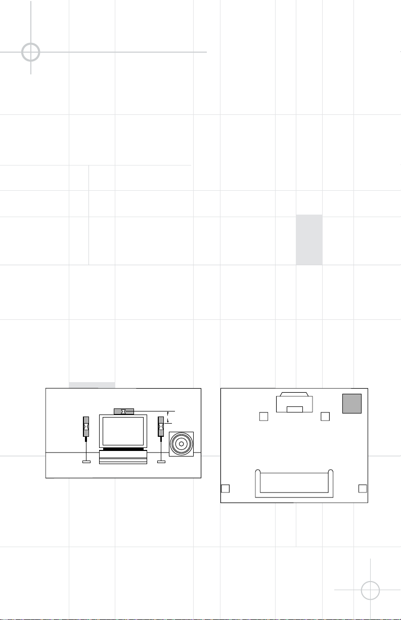
UNPACKING
Feet
Your HTPS-400 subwoofer is
equipped with 2 sets of feet
for use depending on the type
of surface the subwoofer will
be placed on. Enclosed with
this manual is a set of rubber
self-adhesive feet for use on
hard surfaces, such as wood
or tile floors, and a set of
spiked feet for use on
carpeted surfaces. To install
the feet, set the subwoofer
gently on a padded surface
with the bottom side up. If
you are using the rubber
feet, attach them to the four
corners of the unit, covering
the holes. If you are using the
spiked feet, install them by
pressing them into the holes.
The subwoofer may not
perform as well as expected if
you neglect to attach the feet.
Grille
Your HTPS-400 subwoofer has
been packaged with the grille
unattached for shipping
purposes. In some applications,
such as custom installations,
the grille may not be necessary.
In cases where a grille is
needed, carefully align the
grille pegs with the grommets
and insert the grille. The grille
is not designed for frequent
removal, and cannot be
readily removed with bare
hands. If for some reason it
becomes necessary to remove
the grille, it should be pried off
very carefully with a small, flattipped, jewelers’ screwdriver,
taking extra care not to
damage the baffle or the grille.
0–2 ft.
Front view
Top view
SPEAKER PLACEMENT
Experiment with placement for
the most accurate and uniform
bass response throughout the
room. It is important to avoid
blocking the grille of the
subwoofer.
Since the HTPS-400 is videoshielded, it may be placed in
proximity to a television
monitor.
A single HTPS-400 subwoofer
meets THX Select requirements
for a 3000-cubic-foot room.
However, to meet THXUltra
requirements for a 3000cubic-foot room, two or more
HTPS-400 subwoofers are
required. The preamp output
featured on the HTPS-400
simplifies the hookup of
multiple units (see page 4).
Page 4
4
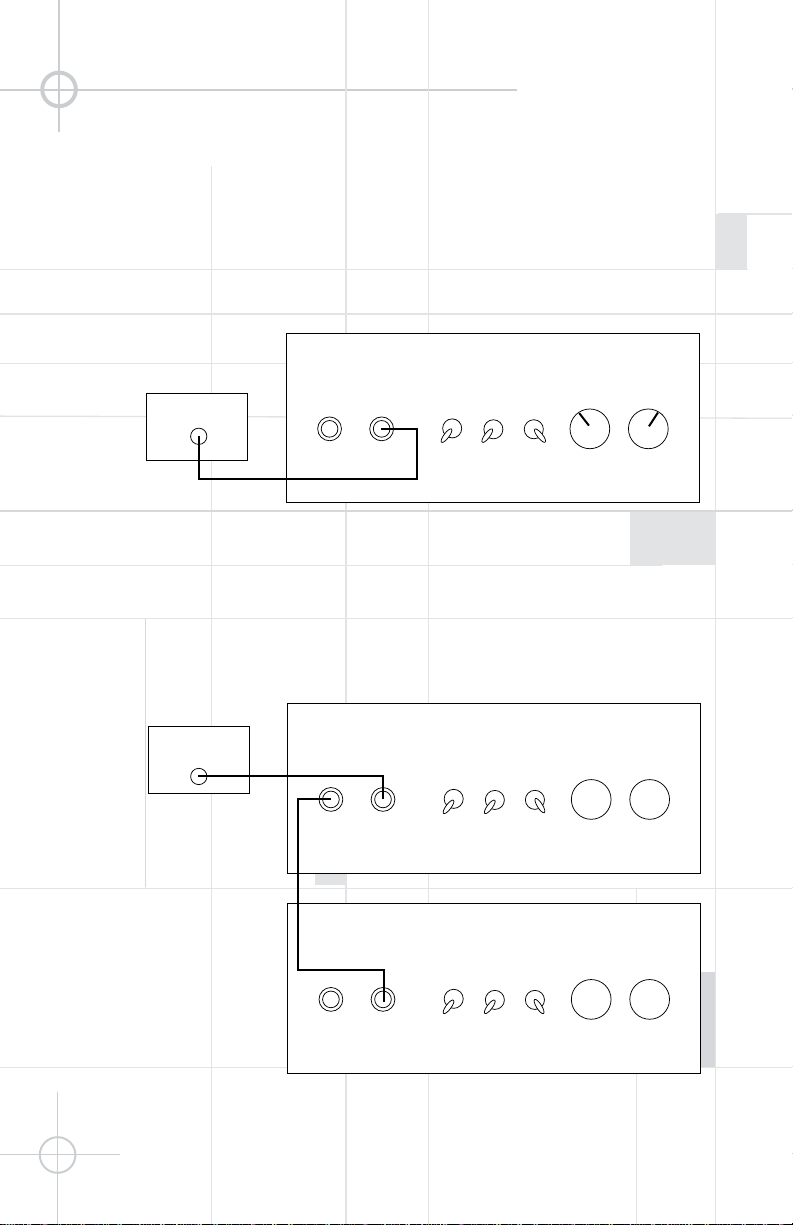
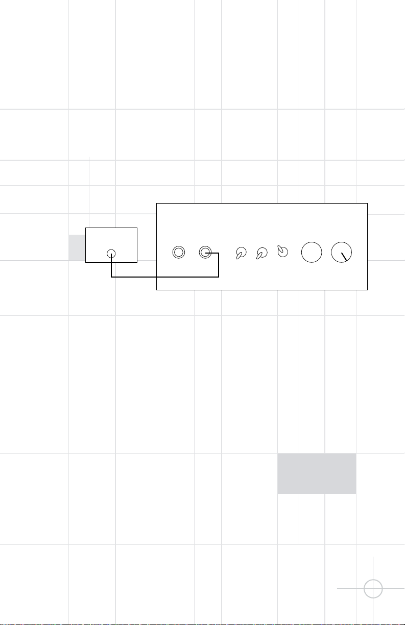
HOOKUP
Line-Level Inputs
Subwoofer
Out
THX®-Certified
Receiver/Processor
OFF
AUTO
ON
OUT
IN
0
°
THX
180
°
NORMAL
MIN.
MAX.
50Hz
150Hz
GREEN–ON
RED–STANDBY
LINE
PHASE
GAIN
CROSSOVER
EQ
THX Mode:
If your surround processor/
receiver is THX-certified:
Note: When the THX/Normal
switch is set to “THX,” the
subwoofer’s internal crossover
and output level control are
bypassed.
Subwoofer
Out
OFF
AUTO
ON
OUT
IN
0
°
THX
180
°
NORMAL
MIN.
MAX.
50Hz
150Hz
GREEN–ON
RED–STANDBY
LINE
PHASE
GAIN
CROSSOVER
EQ
OFF
AUTO
ON
OUT
IN
0
°
THX
180
°
NORMAL
MIN.
MAX.
50Hz
150Hz
GREEN–ON
RED–STANDBY
LINE
PHASE
GAIN
CROSSOVER
EQ
THX®-Certified
Receiver/Processor
Sub 1
Sub 2
To continue enjoying THXquality bass response in a
very large room, two or more
HTPS-400 subwoofers may be
connected in series. For every
3000 cu. ft. of room volume, it
is recommended that you add
one HTPS-400.
Page 5
5
Normal Mode:
Use this hookup for all nonTHX processors, including
Dolby* Digital, DTS
®
, Dolby
Pro Logic* or stereo.
Note: If using Dolby Digital or
DTS, set the crossover
frequency knob fully clockwise
to the maximum position. Make
sure the THX/Normal switch is
in the Normal position.
.
Subwoofer
Out
Receiver/Amplifier
OFF
AUTO
ON
OUT
IN
0
°
THX
180
°
NORMAL
MIN.
MAX.
50Hz
150Hz
GREEN–ON
RED–STANDBY
LINE
PHASE
GAIN
CROSSOVER
EQ
Note: Some receivers/
processors have stereo
subwoofer outputs. In that
case, you must use a “Y”connector (not included) in
order to maximize the
subwoofer’s performance.
Page 6

6
OPERATION
The HTPS-400 contains a
signal-sensing auto turn-on/
turn-off circuit. This feature
will automatically turn the
subwoofer on when you turn
your system on with the power
switch in the “Auto” position
and begin playing any program
material. The subwoofer will
return to standby mode when
no signal is received for
approximately 15 minutes. The
power switch’s “Off” position
is for vacation use only.
The Crossover Frequency
adjustment determines
the highest frequency the
HTPS-400 will reproduce. It
allows a seamless transition
from the subwoofer to the
satellite speakers. Experiment
with this adjustment to
find the crossover frequency
that sounds best with your
speakers.
Note: When the THX/Normal
switch is set to “THX,” the
internal crossover is bypassed.
Crossover frequency is then
adjusted at the THX processor.
Toggle LED
Position Procedure Color
Off Power switch off Red
On Power switch on and playing program material Green
Auto Simply turn off your receiver/processor. The HTPS-400 will No signal present for more
turn off after approximately fifteen minutes. The subwoofer than 15 minutes – Red;
will turn on when your receiver/processor begins playing again. signal present – Green
Crossover Frequency – Normal (non-THX)Modes Only
Output Level (Gain) – Normal (non-THX) Modes Only
Note: When the THX/Normal
switch is set to “THX,” the
output (gain) control is
bypassed. Output level is then
adjusted at the THX processor.
Output
Level
(Gain)
Min. Max.
Min. Max.
Output
Level
(Gain)
Page 7
TROUBLESHOOTING
The Phase switch is used to
adjust the relative polarity of
the subwoofer to the other
speakers. When the speakers
are out of phase, the lowfrequency sound waves will
cancel each other out,
reducing bass response.
The HTPS-400 provides a
convenient phase switch that
allows you to remedy this
situation without relocating
the speakers or changing any
speaker connections. In
normal THX operation, the
Phase switch should be set to
0 degrees so that the subwoofer is operating in phase
with the main speakers. This
should produce a smooth
frequency response up to
80Hz. In rare cases when the
subwoofer is placed more
than 25 feet away from the
main speakers, or where the
subwoofer is not being used
with a THX-certified receiver,
or processor, and speakers,
the 180-degree position may
provide a smoother frequency
response.
Listen to your HTPS-400
subwoofer and main speakers
with the switch in the “0°”
position, then listen to the
same material with the switch
set to “180°”. Decide which
sounds better and leave the
switch in this position. Repeat
this procedure if you change
the location of the subwoofer.
Phase
If there is no output from the
subwoofer:
• Make sure the system is on
and a source is playing.
• Make sure the HTPS-400 is
plugged into an active outlet
and the power switch is in
either the “Auto” or “On”
position.
• If you are using a THXcertified processor/receiver,
make sure the THX/Normal
switch is set to “THX.”
• If you are not using a THXcertified processor/receiver,
make sure the THX/Normal
switch is set to “Normal.”
• Adjust the “Output Level”
(Gain) control.
• Review proper operation of
your receiver/amplifier.
• Check all wires and make
sure they are properly
connected. Make sure none
of the wires are frayed, cut or
punctured.
• If you are not using a THXcertified processor/receiver,
make sure that you have
configured your processor/
receiver so that the subwoofer/
LFE output is on.
If there is no (or low) bass
output:
• Make sure that the subwoofer is plugged into a live
electrical outlet and the
power switch is in either the
“Auto” or “On” position.
• Adjust the “Crossover
Frequency.”
• Adjust the “Output Level”
(Gain) control.
• Change the setting on the
Phase switch.
• If you are not using a THXcertified processor/receiver,
make sure that you have
configured your processor/
receiver so that the subwoofer/LFE output is on.
If you are hearing midrange
frequencies (such as vocals)
through the subwoofer:
• When using the THX mode,
make sure the subwoofer
crossover is activated on your
processor/receiver.
• When using the Normal
Mode, adjust the “Crossover
Frequency” to a lower
frequency.
7
Page 8
JBL Consumer Products
250 Crossways Park Drive, Woodbury, NY 11797
8500 Balboa Boulevard, Northridge, CA 91329
800-336-4JBL (4525) (USA only) www.jbl.com
©2003 Harman International Industries, Incorporated.
JBL is a registered trademark of
Harman International Industries, Incorporated.
Part No.
336077-001
DESIGN GOAL: Bring the thrill of live performance and movie sound to
the homeenvironment bycalling on JBL’s professional engineering leadership.
CROSSOVER NETWORK: THX®-Ultra Certified
WOOFER TYPE:
Aluminum cone with rubber surrounds
ENCLOSURE DESIGN: Sealed
PROFESSIONAL REFERENCE: Cinema Loudspeaker Series
OWNER’S GUIDE
PRO SOUND
COMES HOME
™
PRODUCT LINE:
HT SERIES
MODEL
HTPS-400
HTPS-400
Powered Subwoofer
Amplifier Power 1000 watts
Driver 12" with aluminum cone and
rubber surround, video-shielded
Input THX and normal line level
Output Line level (loop through from input)
Crossover Frequency – 50Hz – 150Hz (continuously adjustable)
Normal Mode
Frequency Response 25Hz – crossover point
(Determined by crossover setting)
Dimensions (H x W x D) 14-5/8" x 14-5/8" x 14-5/8"
371mm x 371mm x 371mm
Weight 62 lb/28kg
SPECIFICATIONS
Occasional refinements may be made to existing products without notice,
but will always meet or exceed original specifications unless otherwise
stated.
THX is a registered trademark of Lucasfilm Ltd.
*Trademarks of Dolby Laboratories.
DTS is a registered trademark of Digital Theater Systems, Inc.
NUMBER:
TWO UNITS MINIMUM
 Loading...