

Page 1
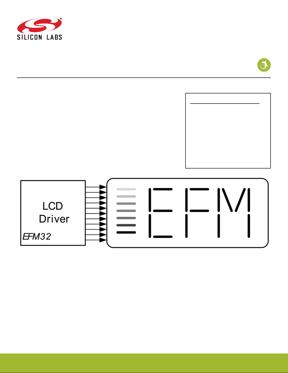
AN0057.0: EFM32 Series 0 LCD Driver
This application note provides a description of how passive segment LCD displays work and how they can be interfaced with the
EFM32.
This application note includes:
• This PDF document
• Source files (zip)
• Example C-code
• Multiple IDE projects
KEY FEATURES
• The ultra-low power LCD driver has
internal bias voltage circuit and boost
converter to minimize external components.
• The voltage boost function enables it to
provide the LCD display with higher
voltage than the supply voltage of the
device.
• The LCD driver supports autonomous
animation and blinking in deep sleep
without CPU intervention.
silabs.com | Building a more connected world. Rev. 1.05
Page 2

AN0057.0: EFM32 Series 0 LCD Driver
1. Device Compatibility
This application note supports multiple device families, and some functionality is different depending on the device.
EFM32 MCU Series 0 consists of:
• EFM32 Gecko (EFM32G)
• EFM32 Tiny Gecko (EFM32TG)
• EFM32 Giant Gecko (EFM32GG)
• EFM32 Leopard Gecko (EFM32LG)
• EFM32 Wonder Gecko (EFM32WG)
Device Compatibility
silabs.com | Building a more connected world. Rev. 1.05 | 2
Page 3
AN0057.0: EFM32 Series 0 LCD Driver
Introduction to LCD Segment Displays
2. Introduction to LCD Segment Displays
Segmented liquid crystal displays (LCDs) are a common way to display information. The extreme low-power LCD driver in the EFM32
enables many applications to use an LCD even in energy critical systems. This document will both discuss how certain types of LCDs
work, how they are driven and how to minimize their energy consumption.
2.1 Passive LCD Displays
This document will only discuss passive segment LCDs. These displays are usually constructed by sandwiching the liquid crystal between two glass plates. By using the voltage dependent, polarizing properties of the liquid crystal material, light transmission through
the LCD glass can be controlled. The display is usually built up by segments that can either block light or let it pass through depending
on the voltage applied over the liquid crystal within that segment.
By having a reflective coating on one side of the glass, ambient light can either be reflected back to the user or blocked by the polarizer
closest to the reflective layer. This blocking of light occurs because the liquid crystal in one state will change the polarization of the light
to allow it to pass both polarizers. In the other state it will not affect the polarization, and the light is then blocked because the two
polarizers are orthogonally oriented with respect to each other.
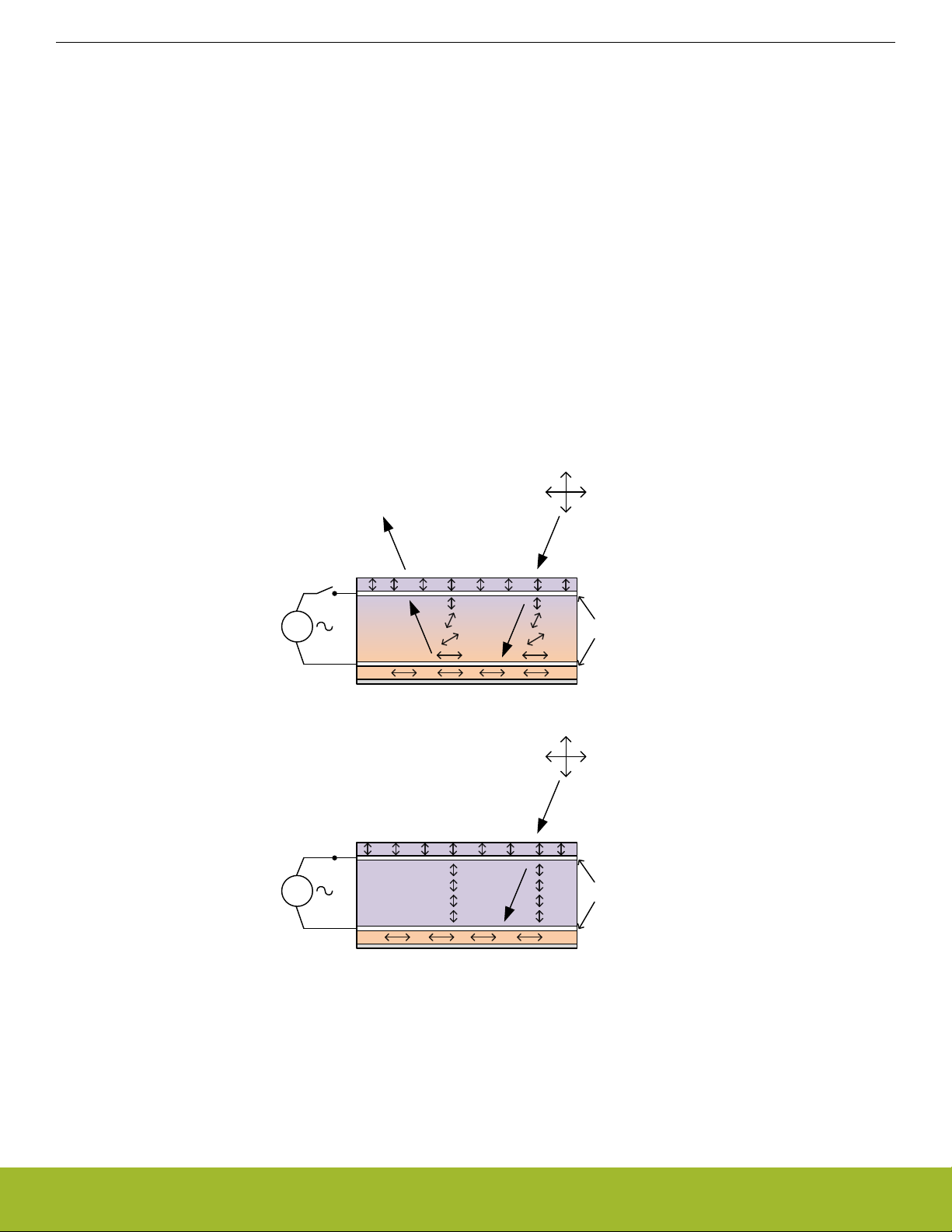
This document will further use the notion that a segment is "on" when it is blocking light and "off" when light can pass through. Some
displays invert this notion by letting light pass through the "on" segments, and having the "off" segments block light. The figure below
illustrates how light polarization is affected when light passes through the polarizers and liquid crystal with and without an applied voltage.
AC
AC
Liquid
Crystal
Liquid
Crystal
Non-
polarized
light
Segment Off
Polarizer
Electrodes
90° Polarizer
Reflective Layer
Non-
polarized
light
Segment On
Polarizer
Electrodes
90° Polarizer
Reflective Layer
Figure 2.1. One LCD Segment with and Without Voltage Applied
When the voltage is applied, the liquid crystal does not change the polarization direction of the light. This causes it to be blocked by the
second polarizer, which is oriented at an orthogonal angle to the first polarizer. If no voltage is applied, the liquid crystal will change the
polarization of the light so that it can pass through both polarizers.
silabs.com | Building a more connected world. Rev. 1.05 | 3
Page 4
AN0057.0: EFM32 Series 0 LCD Driver
Introduction to LCD Segment Displays
2.2 Driving a Display Segment
Segment LCDs do not have any internal driving circuitry. All the display pins are directly connected to each side of the corresponding
segment. The simplest LCD imaginable consist of only one segment with two electrical connections, one for each side of the segment.
The segment is turned on or off by applying a voltage across it. The electric field, or voltage, between the top and bottom of the liquid
crystal between the glass plates directly affects the polarization properties, see Figure 2.1 One LCD Segment with and Without Voltage
Applied on page 3.
Just applying a constant voltage across the segment to turn it on would work, but not for a long time. The problem is that after a short
time the LCD segment will be affected by the DC-current passing through it, mainly through electrolysis effects on the liquid crystal and
electrodes. The solution is to drive the segment with a waveform that has an average 0 DC value. As long as the voltage is switched
fast enough (30 - 100 Hz), it will be the RMS value of the voltage that affects the amount of polarization.
The simplest way to drive a "one segment" LCD with the correct zero DC bias would be to apply two identical and optionally phase
shifted, square waveforms. By shifting the phase of one signal with respect to the other by 180 degrees, the apparent RMS voltage
across the segment goes from 0 to two times the voltage of the two waveforms. See the following figure.
Frame Start Frame End
V
LCD
V
SS
V
LCD
V
SS
V
LCD
V
SS
V
LCD
0 V
-V
LCD
V
LCD
0 V
-V
LCD
Segment 0 Segment 1
COM0
SEG0
SEG1
V
RMS
Resulting Voltage COM0-SEG0
V
RMS
Resulting Voltage COM0-SEG1
On Off
Figure 2.2. Static Driving of Two LCD Segments, One On and One Off
The reason for using two square waveforms, offset from 0 V is that this is simpler to achieve on a microcontroller with a single power
supply. Negative voltages are rarely available, so connecting one side of the LCD segments to ground is not an option.
silabs.com | Building a more connected world. Rev. 1.05 | 4
Page 5
AN0057.0: EFM32 Series 0 LCD Driver
Introduction to LCD Segment Displays
2.2.1 Driving Many Segments: Static Driving
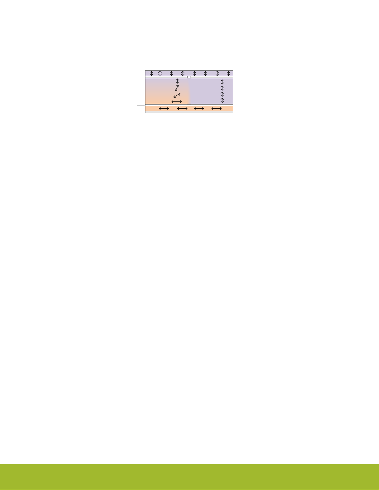
An LCD display most often has more than one segment. Usually the segments are connected with one side common to many of the
other segments, this is called the "common"-electrode. The other side of the segment has its own pin connection, the "segment"-electrode. See the following figure.
Segment
electrode 0
Common
backplane
Liquid
Crystal
OnOff
Segment
electrode 1
Figure 2.3. Common Backplane with Two Segments, One On and One Off
With a statically driven LCD display, there is only one common electrode and each segment has its own segment electrode. Both the
common electrode and segments are driven with a square wave form. Segments that are "on" are driven with a phase shifted waveform
to make the RMS voltage across these segment non-zero. See Figure 2.2 Static Driving of Two LCD Segments, One On and One Off
on page 4.
2.2.2 Driving Many Segments: Multiplexed Driving
With the static driving approach with one segment line for each segment, large displays with many segments would need a large number of the microcontroller pins just to drive the display. By multiplexing several common and segment lines, fewer pins can be used to
drive more segments. The total number of segments that can be driven is the product of the number of common lines and segment
lines. Usually maximum contrast goes down and current consumption goes up with a higher number of common lines.
It is the amplitude of the apparent RMS voltage across a segment that determines if it is on or off. A segment with a low RMS voltage
applied will seem to be off even if the voltage is non-zero. The relationship between apparent RMS voltage across a segment and its
visual properties is non-linear. This non-linearity is utilized when multiplexing several segments on the same driving pins. A segment
does not need to see zero RMS voltage to be perceived as completely off by the user.
Each common line and segment line is driven with waveforms consisting of more than two voltage levels as in the static driving case.
The number of voltage levels are known as "bias" levels. By carefully selecting the waveform of each segment line and common line, it
is possible to make some segments "see" a low RMS voltage, while others "see" a high RMS voltage, even if the segments share either
their common or segment electrode with other segments. See the figure below.
silabs.com | Building a more connected world. Rev. 1.05 | 5
Page 6

AN0057.0: EFM32 Series 0 LCD Driver
Introduction to LCD Segment Displays
Frame Start Frame End
V
LCD
1/2V
LCD
V
SS
V
LCD
1/2V
LCD
V
SS
V
LCD
1/2V
LCD
V
SS
V
LCD
1/2V
LCD
V
SS
V
LCD
1/2V
LCD
0 V
-1/2V
LCD
-V
LCD
V
LCD
1/2V
LCD
0 V
-1/2V
LCD
-V
LCD
Segment 0 Segment 1
COM0
On
COM1
Off On
Segment 2 Segment 3
SEG0
SEG1
Resulting Voltage SEG0-COM0
Resulting Voltage SEG0-COM1
Off
Figure 2.4. Multiplexed Driving of Four LCD Segments
In the figure above there are two segment lines and two common lines. The bias is 1/2, which means there are 3 different voltage levels
possible. The combination of the waveform on COM0 and SEG0 makes the segment between SEG0 and COM0 turn on, while the segment between SEG0 and COM1 is off. Notice the difference in RMS voltage across the two segments.
For a multiplexed display, the difference in RMS voltage between segments that are on and off will be smaller than for a statically driven
display. This means that the visual quality and appearance, such as contrast and viewing angle, must be more carefully calibrated for a
multiplexed display. The contrast can be calibrated in software by adjusting the bias voltage levels within the LCD driver. Viewing angle
and appearance under different lighting conditions should be considered when selecting the actual display.
silabs.com | Building a more connected world. Rev. 1.05 | 6
Page 7

AN0057.0: EFM32 Series 0 LCD Driver
EFM32 LCD Driver
3. EFM32 LCD Driver
This chapter explains some of the features and possibilities of the EFM32 built-in LCD driving peripheral. For a full set of features and
limitations, please see the reference manual for the specific device family.
3.1 Multiplexing
The EFM32 LCD driver can multiplex up to 8 common lines, of which 4 are dedicated common lines and 4 are part of the segment lines
(not available on all parts). The multiplexing waveforms and bias voltage levels are automatically handled within the LCD driver peripheral. The software only needs to set segments on or off and adjust contrast if necessary.
If multiplexing is not needed, static driving of the display is also possible. A statically-driven display can have higher contrast than a
multiplexed display. A static display with only one common line is usually lower power than a multiplexed display, and, in most cases,
current consumption goes up with a larger number of common lines.
3.2 Waveform and Bias Selection
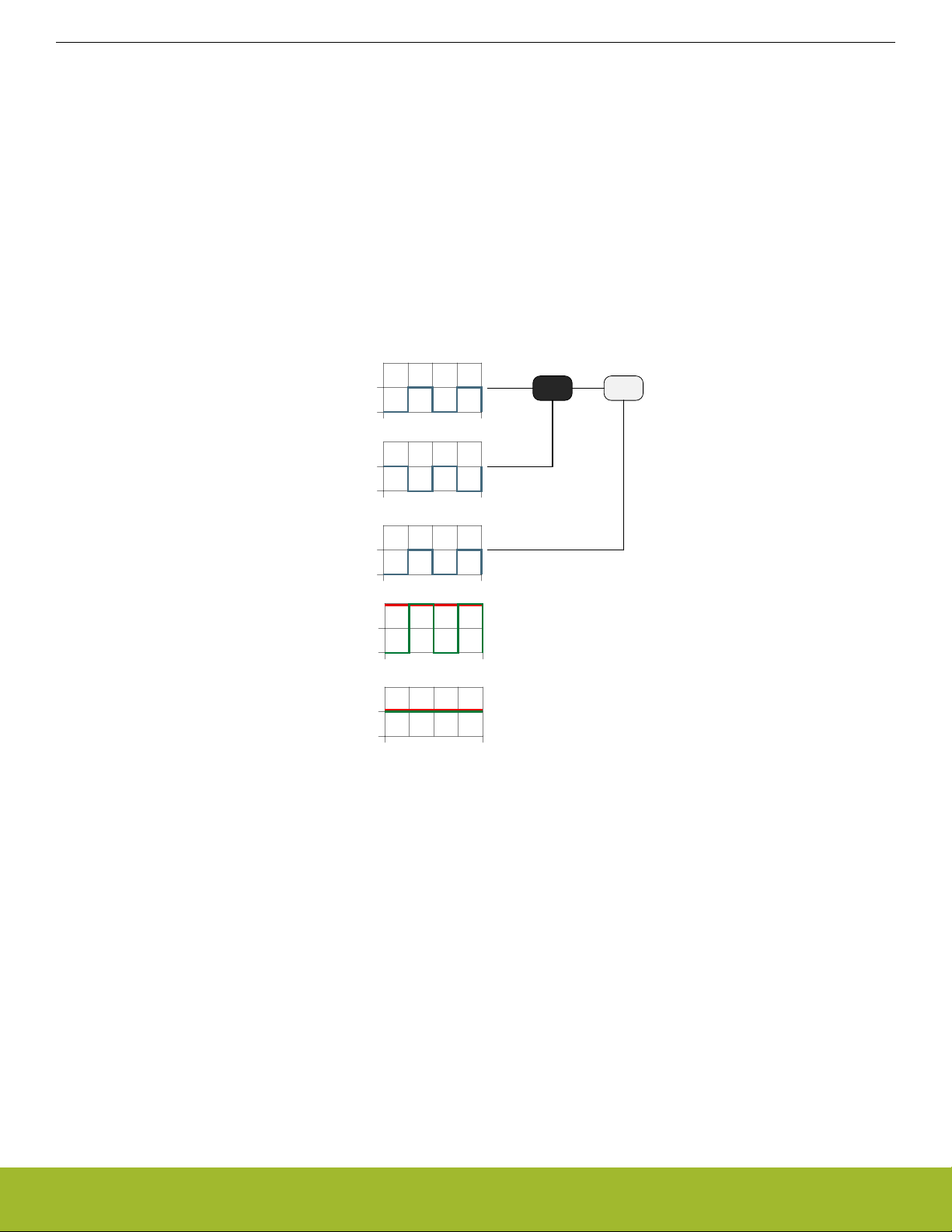
When selecting multiplex mode and number of bias levels according to how many common lines the LCD has, the waveforms are selected automatically by the EFM32 LCD peripheral. Normal and low power waveform modes are selectable with the difference being
that the low power mode achieves zero DC bias over several frames. In other words, the DC bias across LCD segments is not zero
within a frame. This is not a problem for most displays and applications and is the mode almost always recommended.
Figure 3.1 Normal and Low Power Waveform, Only Common Signal Shown on page 7 shows the difference between low power and
normal mode and its larger number of waveform changes within a frame. If flickering or contrast problems occur are observed in lowpower mode, normal mode can be selected instead. An illustration of the different waveforms used, up to and including quadplexed
mode, can be found in the reference manual.
Normal Waveform
)
(V
V
LCD
LC0
)
(2/3V
V
LCD
LC1
)
(1/3V
V
LCD
LC2
)
(V
V
SS
LC3
Frame Start Frame End
Low Power Waveform
)
(V
V
LCD
LC0
)
(2/3V
V
V
LCD
LC1
)
(1/3V
LCD
LC2
)
(V
V
SS
LC3
Frame Start Frame End
Figure 3.1. Normal and Low Power Waveform, Only Common Signal Shown
silabs.com | Building a more connected world. Rev. 1.05 | 7
Page 8

AN0057.0: EFM32 Series 0 LCD Driver
EFM32 LCD Driver
Selecting the correct bias is necessary to provide the waveform generator with enough voltage levels to produce the necessary waveform for the chosen number of common lines. In general 5- to 8-plexed modes need 1/4 bias (5 voltage levels), 3- to 4-plexed modes
need 1/3 bias (4 voltage levels), while 2-plexed mode needs 1/2 bias (3 voltage levels) and static mode needs only 2 voltage levels.
The following table illustrates the need for more bias levels when increasing the number of multiplexed common lines. The difference
between Von and V
sentially infinite. Refer to Figure 3.2 Relative Transmission of Light Through the LCD for Changes in the Applied RMS Voltage on page
9 for an illustration of the non-linear properties of the liquid crystal and why the difference between Von and V
contrast.
is essentially a measurement of the possible contrast. Notice that for the static driven display, the contrast is es-
off
is a measure of
off
Table 3.1. LCD Drive Modes, Bias Setting and Contrast Characteristics
LCD drive mode configuration LCD bias setting Contrast = V
on(RMS)/Voff(RMS)
Static Static Infinite
1:2 multiplex 1/2 2.24
1:2 multiplex 1/3 2.24
1:2 multiplex 1/4 1.85
1:4 multiplex 1/2 1.53
1:4 multiplex 1/3 1.73
1:4 multiplex 1/4 1.65
1:6 multiplex 1/2 1.34
1:6 multiplex 1/3 1.53
1:6 multiplex 1/4 1.53
1:8 multiplex 1/2 1.25
1:8 multiplex 1/3 1.41
1:8 multiplex 1/4 1.45
Note that for some multiplex configurations, contrast actually goes down with an increased number of bias levels. In general a higher
number of bias levels also means higher energy consumption, so for a given number of multiplexed common lines, the lowest possible
number of bias levels should be chosen. Depending on the LCD, contrast might be acceptable even with a lower number of bias levels.
silabs.com | Building a more connected world. Rev. 1.05 | 8
Page 9

AN0057.0: EFM32 Series 0 LCD Driver
EFM32 LCD Driver
3.3 Contrast
Adjusting the contrast of the LCD is only relevant to multiplexed displays because the off segments in multiplexed mode still have a
non-zero RMS voltage across them. The purpose of contrast adjustment is to get the RMS voltage of off segments below a certain
threshold so these segments are perceived as off but there is still a high enough voltage across the on segments for them to be perceived as on. Contrast varies among LCDs and also changes with temperature and voltage, thus making adjustments necessary. See
Figure 3.2 Relative Transmission of Light Through the LCD for Changes in the Applied RMS Voltage on page 9 for an illustration of
the non-linear nature of the liquid crystal material with respect to applied voltage and transmission of light without changing polarization.
100%
90%
Relative
Transmission
10%
Segment off Segment grey
Figure 3.2. Relative Transmission of Light Through the LCD for Changes in the Applied RMS Voltage
3.3.1 Internal Voltage Boost
Some LCDs require higher voltage waveforms to work. The EFM32 Series 0 LCD peripheral includes a built in boost converter to generate voltage higher than the supply voltage of the device. This boost generator can generate voltages up to 3.0 V to 3.6 V from supply
voltages down to the minimum EFM32 Vdd voltage.
The usual sign that boost converter is needed is that LCD contrast goes down and on segments appear dim even with the contrast
adjusted to its highest level. Reduced contrast and even perceived blanking of the display is also a problem at low temperatures and
can be resolved in software by turning on boost converter to generate a higher voltage level. It is not necessary to have the boost converter enabled all the time, it can enabled on the fly when needed. Remember that the boost converter significantly adds to the current
consumption (several microamps typically).
See the reference manual for more information on the external components necessary for using the boost converter and how to enable
and adjust its output voltage.
3.3.2 Contrast Compensation
As mentioned earlier, LCD contrast is affected by both the EFM32 supply voltage and the temperature of the LCD glass. If the system is
intended for operation over a wide range of supply voltages and temperatures, the contrast, and optionally the use of boost converter,
should be adjusted under software control at predetermined thresholds.
Segment on
V
RMS
[V]
The correct contrast adjustment varies between different displays and viewing angles. Exactly at which voltages and temperatures the
boost converter is needed is also dependent on the LCD display itself. Some information can often be found in the LCD glass documentation.
silabs.com | Building a more connected world. Rev. 1.05 | 9
Page 10

AN0057.0: EFM32 Series 0 LCD Driver
EFM32 LCD Driver
3.4 Animation and Blinking
The EFM32 LCD driver includes special features to enable animation and blinking of specific segments without any software intervention. This is useful for displaying continuous animation to signal that a device is alive, without the need to wake up from deep sleep to
update the segments.
The animation feature is available on segments 0 to 7 (or segments 8 to 15) multiplexed with LCD_COM0. The animation is implemented as two programmable 8-bit registers that are shifted left or right every other Animation state for a total of 16 states. The animation
state changes with each frame counter event. See the reference manual for more information on the animation feature and its interface.
The animation registers and shift operation are shown in the following image.
Barrel shift right/left
AREGA7
Seg7
AREGB7
ALOGSEL
AREGA6
AREGB6
Barrel shift right/left
Seg6
AREGA0
Seg0
AREGB0
Figure 3.3. Animation Function with Barrel Shift and Logic Operations
The included software example demonstrates how to enable and configure the blinking and animation features.
3.5 LCD Interrupts
The LCD peripheral contains one interrupt source, the frame counter interrupt. It can be used to time and execute display updates,
animation changes or similar display effects. Since there are no limitations on when the LCD segment registers can be updated, there
is no need to use the frame counter interrupt to time segment updates. The driver supplied in the Gecko SDK Suite and which is used
in the software example with this application note does not use this interrupt. See the reference manual for more information.
3.6 Minimize Energy Consumption
The LCD driver is itself a very low-power peripheral that can operate in deep sleep mode (EM2) from a low-frequency oscillator. When
connecting a display to the EFM32, the capacitive load presented by the LCD results in increased energy consumption. This can be
minimized by optimizing a few parameters.
After the multiplex and bias settings are configured correctly, and low-power waveform is selected, the display refresh rate should be
configured to the lowest possible value that does not cause flickering by setting the frame rate division and prescale values.
The LCD boost converter should not be used unless absolutely necessary. Instead, contrast should first be adjusted to counteract lower
supply voltage or temperatures. Remember that boost converter significantly increases current consumption (several microamps typically).
silabs.com | Building a more connected world. Rev. 1.05 | 10
Page 11

AN0057.0: EFM32 Series 0 LCD Driver
Software Examples
4. Software Examples
This application note includes simple “Hello World” examples that demonstrates use of the LCD peripheral with the Gecko SDK Suite
display drivers, including advanced features such as animation and the voltage boost feature.
4.1 Hello World
This example uses the BSP (Board Support Package) drivers to enable and write a message on the LCD panel. It configures the LCD
peripheral correctly for low current consumption without flickering on the different EFM32 STK. In addition it use the animation feature
of the LCD peripheral to show a rotating circle while the device remains in deep sleep. Note that the rotating circle is only half a circle
on some kits because not all of the circle segments are connected to the animation enabled segment and common lines.
4.2 Porting the LCD Driver to other Displays
This section contains a description of the necessary steps needed to port the BSP LCD driver to other displays with different segment
and common line mapping. Only 4-plexed and 8-plexed displays are covered because these are the only types of displays used by
EFM32 kits. That being said, it should be fairly easy to port the driver to other multiplexed configurations after understanding how to
port the display driver in general.
A segment LCD most often consists of up to three types of "information displaying modules:"
• Individual symbol segments that can be turned on/off. These can be anything from a low battery symbol to Celsius/Fahrenheit temperature indication. The EFM32 STK LCD glass contains several unique symbols. Check the schematics for the kit board to see
available symbol segments.
• 7 Segment numbers. Each digit is built from 7 segments that can be turned on or off to display the numbers from 0 to 9. The EFM32
STK LCD glass contains some of these in the top right corner.
Figure 4.1. Seven Segment Digit with Typical Naming of Segments
• 14 Segment alphanumeric letters, sometimes referred to as a “star burst” or “union jack” display. Each letter or digit is built from 14
segments that can be turned on or off to display any number from 0 to 9 or any uppercase or lowercase letter from A to Z. The
EFM32 STK LCD glass contains some of these in the lower part of the display.
silabs.com | Building a more connected world. Rev. 1.05 | 11
Page 12

AN0057.0: EFM32 Series 0 LCD Driver
Software Examples
• Note that the BSP driver only supports mapping for 14-segment star burst letters. Some LCDs have 15 or 16 segment letters, such
that the mapping of letters to segments must also be changed in addition to the mapping of segments to pins.
Figure 4.2. Fourteen Segment Alphanumeric Letter with Typical Naming of Segments
Figure 4.3. EFM32 Kit LCD Glass Segments
Figure 4.3 EFM32 Kit LCD Glass Segments
on page 12 illustrates how the EFM32 STK LCD glass is built up. Notice the three types of
segment constellations: symbols, 7-segment digits, and 14-segment alphanumerics. The three types of constellations are handled separately in the board support package LCD driver.
silabs.com | Building a more connected world. Rev. 1.05 | 12
Page 13

AN0057.0: EFM32 Series 0 LCD Driver
Software Examples
4.2.1 Understanding the LCD Segment Map
All the mapping information on which segment and common line is connected to which LCD segment is contained in the segmentlcdconfig.h file which varies between the different starter kits and development kits. It is contained in the "config" folder within each kit
software example folder.
To understand how segmentlcdconfig.h is built up, it helps to look at the LCD display mapping figure which is located in the kit schematic document and at the same time have the segmentlcdconfig.h file open. For better understanding of this section, the reader is encouraged to do this.
As an example, consider the first alphanumeric letter in the "EFM_DISPLAY_DEF" #define in segmentlcdconfig.h for the STK3700.
".com[0]" and ".bit[0]" refers to the common and segment line of the first segment (denoted A in the 14-segment letter in Figure
4.2 Fourteen Segment Alphanumeric Letter with Typical Naming of Segments on page 12). ".com[1]" and ".bit[1]" refers to the second
segment (denoted B in the 14-segment letter in Figure 4.2 Fourteen Segment Alphanumeric Letter with Typical Naming of Segments on
page 12) and so on.
Note that in Figure 4.4 EFM32 LCD Segment to Pin Assignment on page 14, the PIN number and COMn refer to the pins of the LCD
panel and not the LCD peripheral on the EFM32. For example, "COM0" is the COM0 pin of the LCD panel, but it is connected to the
LCD_COM7 pin of the EFM32 LCD peripheral in the schematic.
For the first alphanumeric letter in the segmentlcdconfig.h file, the ".com[0] = 1" and ".bit[0] = 13" mapping refer to common line 1 and
segment 13 of the EFM32 LCD peripheral which correspond to COM6 and PIN 2 in the LCD glass figure (Figure 4.4 EFM32 LCD Seg-
ment to Pin Assignment on page 14). Check the schematic document for the connection between LCD display and LCD driver
peripheral.
4.2.2 Porting the LCD Segment Map
This section is an actual step by step description of the porting. Start with selecting a kit with the same number of multiplexed common
lines as your display. Either select the g8xx starter kit for 4-plexed displays, or the STK3300/STK3700 for 8-plexed dis-plays.
Open the segmentlcdconfig.h file for the selected kit. Start with the easiest part, the individual symbol segments, if any. These have
their individual segment and common line #defines at the start of the file. Change a couple of them and check if it is correct by turning
on only those segments. Watch the LCD glass and check if the mapping is correct. This should indicate if the common lines/segment
lines are connected in the expected order. Common problems include reversal of the common and segment lines, errors in the LCD
module documentation, and PCB schematic or layout errors.
Next on the list are the 7-segment digits, if any. These are a bit easier than the 14-segment alphanumerics because they contain fewer
segments per digit. Remember that ".com[0]" and ".bit[0]" refer the common and segment line of the first segment (segment A) in the
digit, ".com[1]" and ".bit[1]" to segment B, and so on. These are most often named A-G in alphabetic order, clockwise around the 7segment digit, starting at the top, as shown in Figure 4.1 Seven Segment Digit with Typical Naming of Segments on page 11.
If the display contains “star burst” letters (14-segment letters), these can be ported in the same way as the 7-segment digits. The numbering is also here usually clockwise, starting from the top. Note that the actual letters selected by the LCD glass manufacturer to represent each segment can vary quite a bit. In any case, the LCD glass on the EFM32 Starter Kits combined with the segmentlcdconfig.h
supplied for this display should make it possible to figure out the correct numbering of the segments. See Figure 4.4 EFM32 LCD Seg-
ment to Pin Assignment on page 14 for the mapping and naming of all the segments in the 8-plexed STK LCD glass.
silabs.com | Building a more connected world. Rev. 1.05 | 13
Page 14

AN0057.0: EFM32 Series 0 LCD Driver
Software Examples
Figure 4.4. EFM32 LCD Segment to Pin Assignment
silabs.com | Building a more connected world. Rev. 1.05 | 14
Page 15

AN0057.0: EFM32 Series 0 LCD Driver
5. Revision History
Revision 1.05
May 2020
• Replaced "V
V
waveforms.
RMS
• Replaced "V
Revision 1.04
February 2018
• Split AN0057 into AN0057.0 and AN0057.1 for MCU Series 0 and MCU Series 1 devices, respectively.
• Added the 1. Device Compatibility section.
• Added support for all EFM32 Series 0 devices which have LCD.
• Re-organized the example code structure.
Revision 1.03
October 2013
" text to "Voltage" in Figure 2.2 Static Driving of Two LCD Segments, One On and One Off on page 4 and added
RMS
" text to "Voltage" in Figure 2.4 Multiplexed Driving of Four LCD Segments on page 6.
RMS
Revision History
New cover layout
Revision 1.02
May 2013
Added software projects for ARM-GCC and Atollic TrueStudio.
Revision 1.01
February 2013
Fixed linker error for DK3550 project.
Revision 1.00
February 2013
Initial revision.
silabs.com | Building a more connected world. Rev. 1.05 | 15
Page 16

Simplicity Studio
One-click access to MCU and
wireless tools, documentation,
software, source code libraries &
more. Available for Windows,
Mac and Linux!
IoT Portfolio
www.silabs.com/IoT
Disclaimer
Silicon Labs intends to provide customers with the latest, accurate, and in-depth documentation of all peripherals and modules available for system and software implementers using or
intending to use the Silicon Labs products. Characterization data, available modules and peripherals, memory sizes and memory addresses refer to each specific device, and "Typical"
parameters provided can and do vary in different applications. Application examples described herein are for illustrative purposes only . Silicon Labs reserves the right to make changes without
further notice to the product information, specifications, and descriptions herein, and does not give warranties as to the accuracy or completeness of the included information. Without prior
notification, Silicon Labs may update product firmware during the manufacturing process for security or reliability reasons. Such changes will not alter the specifications or the performance
of the product. Silicon Labs shall have no liability for the consequences of use of the information supplied in this document. This document does not imply or expressly grant any license
to design or fabricate any integrated circuits. The products are not designed or authorized to be used within any FDA Class III devices, applications for which FDA premarket approval is
required, or Life Support Systems without the specific written consent of Silicon Labs. A "Life Support System" is any product or system intended to support or sustain life and/or health,
which, if it fails, can be reasonably expected to result in significant personal injury or death. Silicon Labs products are not designed or authorized for military applications. Silicon Labs
products shall under no circumstances be used in weapons of mass destruction including (but not limited to) nuclear, biological or chemical weapons, or missiles capable of delivering
such weapons. Silicon Labs disclaims all express and implied warranties and shall not be responsible or liable for any injuries or damages related to use of a Silicon Labs product in such
unauthorized applications.
Trademark Information
Silicon Laboratories Inc.®, Silicon Laboratories®, Silicon Labs®, SiLabs® and the Silicon Labs logo®, Bluegiga®, Bluegiga Logo®, ClockBuilder®, CMEMS®, DSPLL®, EFM®, EFM32®,
EFR, Ember®, Energy Micro, Energy Micro logo and combinations thereof, "the world’s most energy friendly microcontrollers", Ember®, EZLink®, EZRadio®, EZRadioPRO®, Gecko®,
Gecko OS, Gecko OS Studio, ISOmodem®, Precision32®, ProSLIC®, Simplicity Studio®, SiPHY®, Telegesis, the Telegesis Logo®, USBXpress® , Zentri, the Zentri logo and Zentri DMS, ZWave®, and others are trademarks or registered trademarks of Silicon Labs. ARM, CORTEX, Cortex-M3 and THUMB are trademarks or registered trademarks of ARM Holdings. Keil is a
registered trademark of ARM Limited. Wi-Fi is a registered trademark of the Wi-Fi Alliance. All other products or brand names mentioned herein are trademarks of their respective holders.
Silicon Laboratories Inc.
400 West Cesar Chavez
Austin, TX 78701
USA
SW/HW
www.silabs.com/simplicity
Quality
www.silabs.com/quality
Support and Community
community.silabs.com
http://www.silabs.com
 Loading...