

Page 1

TEMPSTAR
HIGHER HOOD
INSTALLATION && OOPERATION MMANUAL
415 VVOLT MMODELS
February 14, 2001 P/N 7610-002-41-86 (Revision A)
Visit Jackson on the Internet at:
www.jacksonmsc.com
HOT WATER SANITIZING UPRIGHT
DOOR DISHMACHINES
Page 2

SECTION
DESCRIPTION PAGE
I. GENERAL SECTION
Specification sof the Tempstar HH 1
Details of the Tempstar HH Data Plate 2
General Notes 3
II. INSTALLATION AND OPERATION INSTRUCTIONS
Installation Instructions 4
Detergent Control 5
Installation Checklist 6
Operation Instructions 7
Water Consumption Issues 8
III. TROUBLESHOOTING SECTION 9
IV. METRIC CONVERSIONS 13
V. DRAWINGS/PARTS SECTION
Dimensions 14
Table Dimensions 15
Main Assembly 16
Control Box Assembly 17
Hood Assembly 18
Cantilever Arm Assembly 19
Yoke Assembly 21
Tub and Frame Assembly 22
Incoming Plumbing Assembly 23
Solenoid Valve Repair Kits 25
Vacuum Breaker Repair Kit 26
Front Bottom View 27
Top Rinse and Wash Arm Assembly 28
Bottom Rinse and Wash Arm Assembly 29
Rinse Head Bushing Assembly 30
Wash Tank Assembly 31
Door Brackets 32
Electrical Schematic 33
VI. IMPORTANT INFORMATION DATA SHEET 34
TABLE OF CONTENTS
i
Page 3

1
PERFORMANCE/CAPABILITIES
OPERATING CAPACITY (RACKS/HOUR)
RACKS PER HOUR 53
DISHES PER HOUR 1325
GLASSES PER HOUR 1325
OPERATING CYCLE (SECONDS)
SELECTION (A)
WASH TIME 45
RINSE TIME 15
TOTAL CYCLE TIME 60
SELECTION (B)
WASH TIME 103
RINSE TIME 15
DWELL TIME 2
TOTAL CYCLE TIME 120
SELECTION (C)
WASH TIME 163
RINSE TIME 15
DWELL TIME 2
TOTAL CYCLE TIME 180
SELECTION (D)
WASH TIME 283
RINSE TIME 15
DWELL TIME 2
TOTAL CYCLE TIME 300
ELECTRICAL REQUIREMENTS
WASH PUMP MOTOR HP 2.0
FULL LOAD AMPS (12 KW BOOSTER HEATER)
VOLTS PHASE AMPS
415 3 27.5
WATER REQUIREMENTS
INLET WATER TEMPERATURE (12 KW) 140
°F
WASH TEMPERATURE (MINIMUM) 150°F
RINSE TEMPERATURE (MINIMUM) 180°F
GALLONS PER RACK 1.36
WATER LINE SIZE I.P.S. (MINIMUM) 3/4”
DRAIN LINE SIZE I.P.S. (MINIMUM) 1-1/2”
FLOW PRESSURE P.S.I. (OPTIMUM) 20
FRAME DIMENSIONS
WIDTH 25 3/4”
DEPTH 25 1/4”
HEIGHT 68 1/2”
STANDARD TABLE HEIGHT 34”
MAXIMUM INSIDE CLEARANCE 27”
RACKS
DISH 20” X 20”
OPTIONAL
GLASS & SILVER 20” X 20”
OPTIONAL
SPECIFICATIONS OF THE TEMPSTAR HH
Page 4
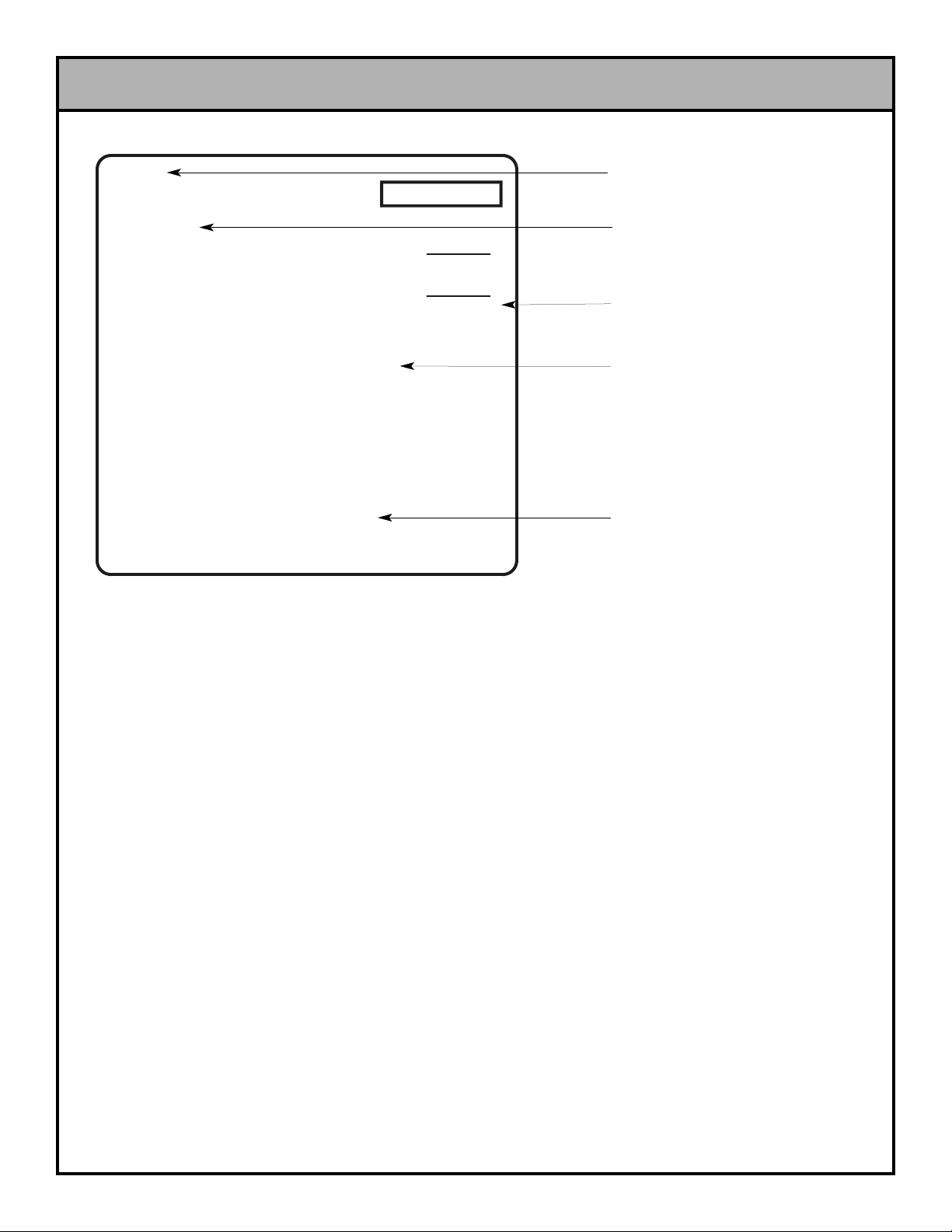
DETAILS OF THE TEMPSTAR-HH DATA PLATE
2
50Hz 3 PH 5 WIRE
TOTAL LOAD
WASH HEATER:
WASH MOTOR:
7.6 AMPS
3.3 AMPS
415 VOLT
27.5 AMPS
2 HP
5 KW
SERIAL NO.:
MODEL:
180°F
150°F
45 SEC
15 SEC
140°F MIN
20 PSI
MINIMUM WASH TEMPERATURE
MINIMUM RINSE TEMPERATURE
WASH CYCLE TI ME A
RINSE CYCLE TIME
INCOMING WATER TEMPERATURE
OPTIMUM FLOW PRESSURE
RINSE HEATER:
16.6 AMPS12 KW
103 SEC
WASH CYCLE TI ME B
163 SEC
WASH CYCLE TI ME C
283 SEC
WASH CYCLE TI ME D
MANUFACTURER’S LOGO
MODEL DESIGNATION
(I.E. TEMPSTAR-HH)
AMPERAGE LOAD
INFORMATION
MINIMUM OPERATING
PARAMETERS (SEE NOTE #1)
MANUFACTURER’S
ADDRESS INFORMATION
DO NOT USE THE ABOVE DATA PLATE TO REPRESENT YOUR DISHMACHINE. THE DATA PLATE ABOVE IS A GENERIC
REPRESENTATION USED ONLY TO SHOW YOU WHERE TO LOCATE INFORMATION. The data plate is located (standing before
the unit) on the right front corner, directly on the tub. Under no circumstance should the data plate be removed from the unit. The data
plate is essential in identifying the particular characteristics of your machine and is of great benefit to installers, operators, and maintenance personnel. It is recommended that you copy down the essential information on the final page in this manual for reference
before installation.
Page 5

Before connecting, operating, or adjusting any of the dishmachines covered in this manual, please carefully read through the entire
manual to familiarize yourself with the machine and its proper operation. This manual contains important operating, safety, and maintenance information concerning your dishmachine. You must follow the instructions and guidelines provided in this manual to ensure
that your warranty remains in effect.
FOR SERVICE PERSONNEL: Jackson MSC Inc. provides technical support for all of the dishmachines detailed in this manual. We
strongly recommend that you refer to this manual before making a call to our technical support staff. Please have this manual with you
when you call so that our staff can refer you, if necessary, to the proper page. Technical support is available from 8:00 a.m. to 5:00 p.m.
(EST), Monday through Friday. Technical support is not available on holidays. Contact technical support toll-free at 1-888-800-5672.
Please remember that technical support is available for service personnel only. Non-service personnel should refer to the list of provided service agencies in this manual for local service support.
NOTES CONCERNING THE TEMPSTAR-HH DATA PLATE:
NOTE 1: This area of the data plate denotes the minimum parameters that must be met in order for your dishmachine to operate at the
designed level of efficiency. Not meeting the required parameters can result in substandard performance of the dishmachine. Do not
refer to the data plate example in this manual for the parameters of your machine; instead, refer to the data plate affixed to the machine.
Not every Tempstar HH model machine operates the same way. If you are unsure of whether or not you are meeting the required minimum parameters, contact your nearest Jackson authorized service agency.
GENERAL NOTES SECTION
3
Page 6

VISUAL INSPECTION: Before installing the unit, check the container and machine for damage. A damaged container is an indicator that there may be some damage to the machine. If there is
damage to both the container and machine, do not throw away the
container. The dishmachine has been inspected and packed at
the factory and is expected to arrive to you in new, undamaged
condition. However, rough handling by carriers or others may
result in there being damage to the unit while in transit. If such a
situation occurs, do not return the unit to Jackson; instead, contact
the carrier and ask them to send a representative to the site to
inspect the damage to the unit and to complete an inspection
report. You must contact the carrier within 48 hours of receiving
the machine. Also, contact the dealer through which you purchased the unit.
UNPACKING THE DISHMACHINE: Once the machine has been
removed from the container, ensure that there are no missing
parts from the machine. This may not be obvious at first. If it is discovered that an item is missing, contact Jackson immediately to
have the missing item shipped to you.
LEVEL THE DISHMACHINE: The dishmachine is designed to
operate while being level. This is important to prevent any damage to the machine during operation and to ensure the best
results when washing ware. The unit comes with adjustable bullet
feet, which can be turned using a pair of channel locks or by hand
if the unit can be raised safely. Ensure that the unit is level from
side to side and from front to back before making any connections.
PLUMBING THE DISHMACHINE: All plumbing connections must
comply with all applicable local, state, and national plumbing
codes. The plumber is responsible for ensuring that the incoming
water line is thoroughly flushed prior to connecting it to any component of the dishmachine. It is necessary to remove all foreign
debris from the water line that may potentially get trapped in the
valves or cause an obstruction. Any valves that are fouled as a
result of foreign matter left in the water line, and any expenses
resulting from this fouling, are not the responsibility of the manufacturer.
CONNECTING THE DRAIN LINE: The drain for the TEMPSTARHH is a gravity discharge drain. All piping from the 1 1/2” FNPT
connection on the wash tank must be pitched (1/4” per foot) to the
floor or sink drain. All piping from the machine to the drain must
be a minimum 1 1/2” I.P.S. and shall not be reduced. There must
also be an air gap between the machine drain line and the floor
sink or drain. If a grease trap is required by code, it should have a
flow capacity of 5 gallons per minute.
WATER SUPPLY CONNECTION: Ensure that you have read the
section entitled “PLUMBING THE DISHMACHINE” above before
proceeding. Install the water supply line (3/4” pipe size minimum)
to the dishmachine line strainer using copper pipe. It is recommended that a water shut-off valve be installed in the water line
between the main supply and the machine to allow access for service. The water supply line is to be capable of 20 PSI “flow” pressure at the recommended temperature indicated on the data plate.
Do not confuse static pressure with flow pressure. Static pressure
is the line pressure in a “no flow” condition (all valves and services
are closed). Flow pressure is the pressure in the fill line when the
fill valve is opened during the cycle.
It is also recommended that a shock absorber (not supplied with
the TEMPST AR-HH model) be installed in the incoming water line.
This prevents line hammer (hydraulic shock), induced by the solenoid valve as it operates, from causing damage to the equipment.
PLUMBING CHECK: Slowly turn on the water supply to the
machine after the incoming fill line and the drain line have been
installed. Check for any leaks and repair as required. All leaks
must be repaired prior to placing the machine in operation.
ELECTRICAL POWER CONNECTION: Electrical and grounding
connections must comply with the applicable portions of the
National Electrical Code ANSI/NFPA 70 (latest edition) and/or
other electrical codes.
Disconnect electrical power supply and place a tag at the disconnect switch to indicate that you are working on the circuit.
The dishmachine data plate is located on the right side and to the
front of the machine. Refer to the data plate for machine operating requirements, machine voltage, total amperage load and serial number.
To install the incoming power lines, open the control box. This will
require taking a phillips head screwdriver and removing the four
(4) screws on the front cover of the control box. Install 3/4” conduit
into the pre-punched holes in the back of the control box. Route
power wires and connect to power block and grounding lug. Install
the service wires (L1, L2, L3 and N) to the appropriate terminals
as they are marked on the terminal block. Install the grounding
wire into the lug provided. Tighten the connections and perform
the “pull test”. The tightened wires should remain in place after
giving the wires a moderate pull to see if they will come loose.
It is recommended that “DE-OX” or another similar anti-oxidation
agent be used on all power connections.
VOLTAGE CHECK: Ensure that the power switch is in the OFF
position and apply power to the dishmachine. Check the incoming
power at the terminal block and ensure it corresponds to the voltage listed on the data plate. If not, contact a qualified service
agency to examine the problem. Do not run the dishmachine if the
voltage is too high or too low. Shut off the service breaker and
mark it as being for the dishmachine. Advise all proper personnel
of any problems and of the location of the service breaker.
Replace the control box cover and tighten down the screws.
INSTALLATION INSTRUCTIONS
4
Page 7

Detergent usage and water hardness are two factors that contribute greatly to how efficient your dishmachine will operate. Using detergent in the proper amount can become, in time, a source of substantial savings. A qualified water treatment specialist can tell you what
is needed for maximum efficiency from your detergent, but you should still know some basics so you’ll understand what they are talking about.
First, you must understand that hard water greatly effects the performance of the dishmachine. Water hardness is the amount of dissolved calcium and magnesium in the water supply . The more dissolved solids in the water, the greater the water hardness. Hard water
works against detergent, thereby causing the amount of detergent required for washing to increase. As you use more detergent, your
costs for operating the dishmachine will increase and the results will decrease. The solids in hard water also may build-up as a scale
on wash and rinse heaters, decreasing their ability to heat water. Water temperature is important in removing soil and sanitizing dishes. If the water cannot get hot enough, your results may not be satisfactory . This is why Jackson recommends that if you have installed
the machine in an area with hard water, that you also install some type of water treatment equipment to help remove the dissolved
solids from the water before it gets to the dishmachine.
Second, hard water may have you adding drying agents to your operating cycle to prevent spotting, when the real problem is deposited solids on your ware. As the water evaporates off of the ware, the solids will be left behind to form the spotting and no amount of drying agent will prevent this. Again, using treated water will undoubtedly reduce the occurrences of this problem.
Third, treated water may not be suitable for use in other areas of your operation. For instance, coffee made with soft water may have
an acid or bitter flavor. It may only be feasible to install a small treatment unit for the water going into the dishmachine itself. Discuss
this option with your qualified water treatment specialist.
Even after the water hardness problems have been solved, there still must be proper training of dishmachine operators in how much
detergent is to be used per cycle. Talk with your water treatment specialist and detergent vendor and come up with a complete training program for operators. Using too much detergent has as detrimental effects as using too little. The proper amount of detergent must
be used for job. It is important to remember that certain menu items may require extra detergent by their nature and personnel need to
be made aware of this. Experience in using the dishmachine under a variety of conditions, along with good training in the operation of
the machine, can go a long way in ensuring your dishmachine operates as efficiently as possible.
Certain dishmachine models require that chemicals be provided for proper operation and sanitization. Some models even require the
installation of third-party chemical feeders to introduce those chemicals to the machine. Jackson does not recommend or endorse any
brand name of chemicals or chemical dispensing equipment. Contact your local chemical distributor for questions concerning these
subjects.
Some dishmachines come equipped with integral solid detergent dispensers. These dispensers are designed to accommodate detergents in a certain sized container. If you have such a unit, remember to explain this to your chemical distributor upon first contacting
them.
As explained before, water temperature is an important factor in ensuring that your dishmachine functions properly . The data plate located on each unit details what the minimum temperatures must be for either the incoming water supply , the wash tank and the rinse tank,
depending on what model of dishmachine you have installed. These temperatures may also be followed by temperatures that Jackson
recommends to ensure the highest performance from you dishmachine. However, if the minimum requirements are not met, the
chances are your dishes will not be clean or sanitized. Remember, a dish can look clean, but it may not be sanitized. Instruct your dishmachine operators to observe the required temperatures and to report when they fall below the minimum allowed. A loss of temperature can indicate a much larger problem such as a failed heater or it could also indicate that the hot water heater for your operation is
not up to capacity and a larger one may need to be installed.
There are several factors to consider when installing your dishmachine to ensure that you get the best possible results from it and that
it operates at peak efficiency for many years. Discuss your concerns with your local chemical distributor and water treatment specialist before there is a problem.
DETERGENT CONTROL
5
Page 8

CHECK OFF THE FOLLOWING ITEMS AS THEY ARE COMPLETED BEFORE PROCEEDING TO OPERATION OF DISHMACHINE.
Has the dishmachine been checked for concealed/hidden damage?
Has the dishmachine and the surrounding area been properly vented in accordance with all applicable codes?
Has the dishmachine been properly leveled?
Has the drain plumbing been installed with an air gap?
Has the service voltage been checked to ensure that it meets the electrical requirements listed on the dishma-
chine’s data plate?
Has the dishmachine been properly grounded?
Has the dishmachine circuit breaker/service breaker been sized correctly, given the dishmachine’s load, and has it
been marked clearly and identified to all pertinent personnel?
Has the incoming water supply been flushed for debris?
Is the hot water supply at the minimum temperature as indicated on the dishmachine data plate?
Is the incoming water supply at 20 PSI?
Is the incoming water supply line at 3/4” minimum?
Have the pan strainer and pump suction strainer been installed?
Has the overflow pipe been installed?
Have the wash arms been installed?
Have the rinse arms been installed?
INSTALLATION CHECKLIST
6
Page 9

PREPARATION: Before proceeding with the start-up of the unit,
verify the following:
1. The pan strainer and pump suction strainer are in
place and are clean.
2. The overflow tube and o-ring are installed.
3. That the wash and rinse arms are screwed securely
into place and that their endcaps are tight. The wash
and rinse arms should rotate freely.
POWER UP: To energize the unit, turn on the power at the service
breaker. The voltage should have been previously verified as
being correct. If not, the voltage will have to be verified.
FILLING THE WASH TUB: For the initial fill, ensure that the cycle
selection switch is in the “AUTO” (automatic) position, and place
the power switch in the “ON” position. The unit will fill automatically. Open the doors and verify that the water level is correct.
Hereafter, the water level is controlled by the overflow tube. Verify
that the drain stopper is preventing the wash tub water from draining excessively. There may be some slight leakage from the drain
hole. Verify that there are no other leaks on the unit before proceeding any further. The wash tub must be completely filled before
operating the wash pump to prevent damage to the component.
Once the wash tub is filled, the unit is ready for operation.
WARE PREPARATION: Proper preparation of ware will help
ensure good results and less re-washes. If not done properly,
ware may not come out clean and the efficiency of the dishmachine will be reduced. It is important to remember that a dishmachine is not a garbage disposal and that simply throwing
unscraped dishes into the machine simply defeats the purpose
altogether of washing the ware. Scraps should be removed from
ware prior to being loaded into a rack.
Pre-rinsing and pre-soaking are required, especially for silverware
and casserole dishes. Place cups and glasses upside down in
racks so that they do not hold water during the cycle. The dishmachine is meant not only to clean, but to sanitize as well, to
destroy all of the bacteria that could be harmful to human beings.
In order to do this, ware must be properly prepared prior to being
placed in the machine.
DAILY MACHINE PREPARATION: Refer to the section entitled
“PREP ARATION” at the top of this page and follow the instructions
there. Afterwards, check that all of the chemical levels are correct
and/or that there is plenty of detergent available for the expected
workload.
WARM-UP CYCLES: For a typical daily start-up, it is recommended to run the machine through 3 cycles to ensure that all of
the cold water is out of the system and to verify that the unit is
operating correctly. To cycle the machine, ensure that the power
is on and that the tub has filled to the correct level. Lift the doors
and the cycle light will illuminate. When the light goes out, close
the doors, the unit will start, run through the cycle, and shut off
automatically . Repeat this two more times. The unit should now be
ready to proceed with the washing of ware.
WASHING A RACK OF WARE: To wash a rack, open the doors
completely (being careful for hot water that may drip from the
doors) and slide the rack into the unit. Close the doors and the
unit will start automatically . Once the cycle is completed, the cycle
light will turn off, open the door (again watching for the dripping hot
water) and remove the rack of clean ware. Replace with a rack of
soiled ware and close the doors. The process will then repeat
itself.
OPERATIONAL INSPECTION: Based upon usage, the pan
strainer may become clogged with soil and debris as the workday
progresses. Operators should regularly inspect the pan strainer to
ensure it has not become clogged. If the strainer does, it will
reduce the washing capability of the machine. Instruct operators
to clean out the pan strainer at regular intervals or as required by
work load.
SHUTDOWN AND CLEANING: At the end of the workday, close
the doors. When the unit completes the cycle, turn the power
switch to the OFF position and open the doors. Remove and clean
the pan strainer. Remove the drain stopper from the tub and allow
the tub to drain (NOTE: The wash tank water will be hot so caution is advised). Once the wash tub is drained, remove the pump
suction strainer. Remove soil and debris from the strainer and set
to the side. Unscrew the wash and rinse arms from their manifolds. Remove the endcaps and flush the arms with water. Use a
brush to clean out the inside of the arms. If the nozzles appear to
be clogged, use a toothpick to remove the obstruction. Wipe the
inside of the unit, removing all soil and scraps. Reassemble the
wash and rinse arms and replace them in the unit. The arms only
need to be hand tight, do not use tools to tighten them down.
Reinstall the drain stopper and strainers and close the doors.
OPERATION INSTRUCTIONS
7
Page 10

W
ATER CONSUMPTION ISSUES AND EFFICIENCY
The Tempstar HH provides you, the customer, with the ability to control the hourly rack capacity of the machine. Extending the wash
cycle to wash severely soiled ware, such as mixing bowls, does not increase the machine’s water consumption. However, selecting a
longer time cycle does lower the amount of dishes the machine will be able to wash per hour. It is important for operators to select the
correct wash cycle depending on the amount of washing required. Not every rack of dishes requires the machine to be set on the
longest wash cycle!
Using good prescrapping procedures and observing the results of individual racks of ware, operators will soon gain the experience and
knowledge required to ensure that the Tempstar HH operates at peak efficiency for your needs.
Water hardness and detergent usage will also effect the results of the Tempstar HH. This manual provides a page on Detergent Control.
It is recommended that owners and operators take the time to carefully review this section in order to ensure that everything is done to
make sure the Tempstar HH operates at peak performance!
WATER CONSUMPTION ISSUES
8
Page 11

WARNING: Inspection, testing and repair of electrical equipment should only be performed by a qualified service techni-
cian. Many of the tests require that the unit have power to it and live electrical components be exposed. USE
EXTREME CAUTION WHEN TESTING THE MACHINE.
TROUBLESHOOTING SECTION
9
Possible Cause A ction
Faulty rinse solenoid valve. Repair or replace valve as required.
Faulty door switch.
Verify the wiring of the switch; if correct,
replace the switch.
Fouled/faulty high level probe.
Clean probe if fouled. If clean and still not
working, replace.
Service breaker tripped.
Reset. If the breaker trips again, contact an
electrician to verify the amp dr aw of the
machine.
Machine not connected to power source.
Verify that the machine has been pr operly
connected to the power source.
Faulty power switch.
Verify the wiring of the switch; if correct,
replace the switch.
Timer motor faulty.
Verify that the timer is rotating. If not, check
to see that the motor is receiving power. If
so, replace the motor and/or timer
assembly.
Wash motor faulty/damaged.
Verify that the wash motor is getting power.
If so, replace the motor.
Wash motor contactor faulty.
Check for continuity; if contacts are open,
replace the contactor.
Machine is in Delime mode.
Change "Operation Mode" from Delime to
Normal position.
Dishmachine runs continuously in the wash
cycle.
Dishmachine will not fill after the door is
closed. Power "ON" light is not illuminated.
Dishmachine will not run after the door is
closed. Power "ON" light is illuminated and
unit is filling.
Symptom
Dishmachine will not fill after the door is
closed. Power "ON" light is illuminated.
Page 12

WARNING: Inspection, testing and repair of electrical equipment should only be performed by a qualified service techni-
cian. Many of the tests require that the unit have power to it and live electrical components be exposed. USE
EXTREME CAUTION WHEN TESTING THE MACHINE.
TROUBLESHOOTING SECTION
10
Possible Cause A ction
Wash cycle delay timer is faulty.
During the wash cycle, the cam timer will
move for the first 30 seconds of the wash
cycle. The cycle delay timer will then cause
the cam timer to stop, in order to increase
the length of the wash cycle. T he red light
on the delay timer is in control of the cam
timer. If the r ed light is not turning on (only
during cycles B, C or D), replace the cycle
timer.
Wash cycle delay timer settings are not
correctly adjusted.
If the wash cycle delay timer and rotating
cam timer are working correctly, the time
cycles on the delay timer may be incorrectly
adjusted. Adjust the delay potent iometer
corresponding to the B, C or D cycle. Rerun
the appropriate cycle and see if the
adjustment has made any change in the
length of the wash cycle. If not, replace the
cycle delay timer.
Cam timer is faulty.
Confirm that the wash cycle delay timer is
functioning correctly (see above).
Confirm that the timer motor is receiving
power. If it is, replace the motor and/or
timer assembly.
Make sure there are no obstructions w hich
limit the rotation of the cam timer.
Faulty heater element.
Check element for continuity; if open,
replace the heater.
Faulty heater contactor. Replace the contactor.
Misadjusted/faulty thermost at(s).
Verify operation and setting of thermostats,
replace if necessary.
Wash or rinse heater does not work.
Dishmachine runs continuously in the wash
cycle.
Symptom
Page 13

WARNING: Inspection, testing and repair of electrical equipment should only be performed by a qualified service techni-
cian. Many of the tests require that the unit have power to it and live electrical components be exposed. USE
EXTREME CAUTION WHEN TESTING THE MACHINE.
TROUBLESHOOTING SECTION
11
Possible Cause A ction
Clogged or obstructed rinse arms. Remove and clean rinse arms.
Low incoming water pressure.
Adjust the water pressur e regulator to
ensure that there is 20 PSI flow.
Y-strainer is clogged. Clean out Y-strainer.
Faulty rinse heater.
Check element for continuity; if open,
replace the heater.
Misadjusted/faulty thermost at(s).
Verify operation and setting of thermostats,
replace if necessary.
Rinse thermometer is defective. Replace thermometer.
Faulty wash heater.
Check element for continuity; if open,
replace the heater.
Misadjusted/faulty thermost at(s).
Verify operation and setting of thermostats,
replace if necessary.
Wash thermometer is defective. Replace thermometer.
Improper spring tension.
Adjust spring tension as required by
loosening (not removing) spring bolt nuts
and adjusting the tension. Tighten nuts back
when done.
Doors will not close completely.
Wash water not reaching required
temperature.
Symptom
Rinse water not reaching requir ed
temperature.
Dishmachine fills slowly and/or the rinse is
weak.
Page 14

WARNING: Inspection, testing and repair of electrical equipment should only be performed by a qualified service techni-
cian. Many of the tests require that the unit have power to it and live electrical components be exposed. USE
EXTREME CAUTION WHEN TESTING THE MACHINE.
TROUBLESHOOTING SECTION
12
Possible Cause A ction
Obstruction in door channel. Remove the obstruction.
Doors are not square with f rame. Adjust the frame to accommodate the
doors.
Wash pump seal defective. Replace the seal.
Petcock or pump drain (if equipped) not
shut/tight.
Close or tighten.
Loose hoses (hoseclamps) on the wash
pump.
Tighten hose clamps.
Defective rinse solenoid.
Repair or replace the rinse solenoid as
required.
Faulty rinse microswitch on cam timer . Replace microswitch on cam timer.
No water to machine.
Verify that there is water at 20 PSI
connected to the machine.
Machine temperatures are not up to the
minimum requirements.
Verify that incoming water, rinse water, and
wash water match the required
temperatures as listed on the machine dat a
plate.
No detergent/too much detergent.
Adjust detergent concentration as required
for the amount of water held by the
machine.
Wash arms jammed. Free up wash arms.
Dishes are not coming clean.
Doors will not close completely.
Will not rinse during autocycle.
Symptom
Water leak at the wash pump.
Page 15

METRIC CONVERSIONS
13
LENGTH
IMPERIAL METRIC
1 INCH 2.54 cm
1 FOOT (12 INCHES) 0.3048 m
1 YARD (3 FEET) 0.9144 m
1 MILE (1760 YARDS) 1.6093 km
FLUID CAP
ACITY
IMPERIAL
METRIC
1 GALLON (US) 3.785412 L
1 QUART (US) 946.3539 mL
1 PINT (US) 473.1765 mL
1 FLUID OUNCE (US) 29.574 mL
SPEED
IMPERIAL METRIC
1 FOOT/MINUTE 0.3048 m/m
1 FOOT/SECOND 0.3048 m/s
1 MILE/HOUR 1.609344 km/h
AREA
IMPERIAL METRIC
1 SQUARE INCH (in2) 6.4516 cm
2
1 SQUARE FOOT (ft2) 0.0929 m
2
1 SQUARE YARD (yd2) 0.8361 m
2
1 SQUARE MILE 2.59 km
2
VOLUME
IMPERIAL
METRIC
1 CUBIC INCH (in3) 16.3871 cm
3
1 CUBIC FOOT (ft3) 0.02831 m
3
1 CUBIC YARD (yd2) 0.7645549 m
3
FLOW
IMPERIAL METRIC
1 GALLON/MINUTE 0.0038 m3/min
1 GALLON/HOUR 1.0515 mL/s
TEMPERATURE CONVERSION
°F = °C x 1.8 + 32 Example: °F = 32°C x 1.8 + 32 = 89.6°F
°C = (°F - 32)/1.8 Example: °C = (100°F - 32)/1.8 = 37.8°C
UNITS OF MEASURE
Length W
eight Area Volume Conveyor Speed
(United States) In. lb. in
2
in
3
ft/min
(Metric) cm kg cm
2
cm
3
m/min
Page 16

DIMENSIONS
14
P.S. C-ELECTRICAL CONNECTION
DISHTABLE 4"
ALL DIMENSIONS IN INCHES
68 1/2
73 3/4
86 1/4
15 3/8
25 1/4
3
25
LEGEND:
A
- DRAIN 1 1/2” I.P.S.
B - WATER INLET 3/4” I.P.S.
C - ELECTRICAL CONNECTION
D - STANDARD WALL CLEARANCE WITH DISHTABLE 4”
D
A
D
B
C
A
12 3/4
7 1/2
34
12 1/4
Page 17

TABLE DIMENSIONS
15
TABLE DIMENSIONS
CORNER INSTALLATION
TABLE DIMENSIONS
CONNECTION TO DISHMACHINE
TABLE DIMENSIONS
STRAIGHT THROUGH INSTALLATION
20 1/2”
OPENING
25 1/4”
2 1/4”
4”
MIN.
2 1/2”
4”
MIN.
20 1/2”
OPENING
25 1/4”
20 1/2”
3/4”
1 1/2” ROLL
4”
MIN
2 1/2”
25 1/4”
20 1/2”
OPENING
25 1/4”
Page 18

MAIN ASSEMBLY
16
ITEM QTY DESCRIPTION MFG NO.
01 1 Door, Upper, Front 5700-002-13-73
02 2 Door, Upper, Left and Right 5700-031-76-85
03 1 Door, Lower, Front 5700-031-76-77
*04 1 Door, Lower, Left 5700-031-76-79
05 1 Cover, Front Panel 5700-002-01-42
06 1 Incoming Plumbing Asssembly 5700-041-88-90
07 6 Glide, Upper Door 5700-002-00-83
08 6 Glide, Lower Door 5700-002-23-64
09 1 Cantilever Arm Assembly 5700-002-06-42
10 1 Door, Lower, Right 5700-031-76-80
11 1 Door Handle Weldment 5700-002-00-90
12 1 Tub Assembly 5700-002-01-25
13 1 Control Box Assembly 5700-002-34-14
01
03
*04
*02
05
06
02
*07
*08
09
10
12
13
11
* Represents an item not shown.
Page 19

CONTROL BOX ASSEMBLY
17
ITEM QTY DESCRIPTION MFG NO.
01 1 Thermostat, 48 Lead 6685-111-68-48
02 1 Liquid Level Control 6680-200-08-21
03 1 Terminal Block, 3 Pole 5940-011-48-27
1 Snap-In Terminal Block 5940-500-02-19
1 Din Rail 5700-000-43-60
04 1 Relay, 240V 50/60HZ Top Mount 5945-111-47-51
05 2 Contactor, 4 Pole 220V 1 Phase 5945-109-01-69
06 1 Wire Lug 2 AWG HO 14 AWG 5940-200-76-00
07 1 Thermostat, 96 Lead 6685-111-68-49
08 1 Timer, 4CKT 208-230V Single REV 5945-306-14-00
09 1 Holder, Fuse #350 / 330 5920-401-03-14
10 1 Contactor, 2 Pole, 460V 20 Amp 5945-002-17-48
11 1 Timer, 240V Wash Cycle Delay 5945-002-13-78
12 1 Light, Red 5945-504-07-18
13 1 Light, Green Indicator 5945-504-08-18
14 1 Light, Amber 5945-504-06-18
15 1 Switch, 8 Button Tap Touch 5930-001-99-51
01 02 03 05 07 08 09 1004 1106
12
13 14 15
Page 20

HOOD ASSEMBLY
18
ITEM QTY DESCRIPTION MFG NO.
01 2 Cantilever A rm Support Bracket 5700-031-88-00
02 1 Hood Weldment 5700-002-01-23
03 28 Locknut, 1/4"- 20 S/S Hex w/Nylon Inserts 5310-374-01-00
*04 1 Right Rear Inner Door Guide 5700-031-76-32
05 1 Right Rear Outer Door Guide 5700-031-76-35
06 1 Left Rear Outer Door Guide 5700-031-76-34
07 1 Left Rear Inner Door Guide 5700-031-76-33
08 24 Washer, 1/4" ID S/S 5311-174-01-00
09 24 Bolt, 1/4"- 20 X 1/2" Long Hex 5305-274-02-00
10 2 Right/Left Front Outer Door Guide 5700-031-76-85
11 2 Right/Left Front Hood Support Weldment 5700-002-17-68
12 2 Right/Left Front Inner Door Guide 5700-031-76-82
01
02
*05
*04
06
*07
08
09
*11
12
10
*11
*12
03
*10
03
* Represents an item not shown.
Page 21

CANTILEVER ARM ASSEMBLY
19
01 02 03 04- SEE YOKE
ASSEMBLY PAGE
05
07
06
15
16
17
141113
09
12
10
08 09 11
18
Page 22

CANTILEVER ARM ASSEMBLY (CONTINUED)
20
ITEM QTY DESCRIPTION MFG NO.
01 4 Locknut, 1/4"- 20 S/S Hex w/Nylon Insert 5310-374-01-00
02 2 Cantilever A rm Support Bracket 5700-031-88-00
03 6 Wear Button, 1/2" UHMW 5700-011-88-01
04 2 Yoke Assembly 5700-000-75-77
05 1 Cantilever A rm 5700-031-92-44
06 2 Rod, Spring Connecting 5700-002-00-91
07 1 Handle, F ront Door Weldment 5700-002-00-90
08 2 Screw, 1/4"- 20 1-1/2" Long Hex Head 5305-274-23-00
09 4 Washer, 1/4" I D S/S 5311-174-01-00
10 2 Sleeve, Cantilever Arm 5700-000-85-69
11 4 Locknut, 1/4"- 20 S/S Low Profile W/ nylon Insert 5310-374-02-00
12 2 Screw, 1/4"- 20 X 1/2" Long Hex Head 5305-274-02-00
13 2 Spacer, PB Bolt 5700-000-29-40
14 2 Connecting Link 5700-021-92-45
15 4 Plate, Spring Multiplier 5700-002-00-88
16 4 Spring, Cantilever Door 5340-111-35-22
17 2 Bolt, Cantilever Hanger Eye 3/8"- 16 5306-956-05-00
18 4 Nut, 3/8"- 16 S/S Hex 5310-276-01-00
Page 23

YOKE ASSEMBLY
21
ITEM QTY DESCRIPTION MFG NO.
01 1 Cotter Pin, 3/32 X 3/4" 5315-207-01-00
02 1 Bushing 3120-100-03-00
03 2 Washer, Nylon 5311-369-03-00
04 1 Clevis Pin 5315-700-05-00
05 1 Yoke, Finished 5700-000-75-78
06 1 Nut, Center Lock 3/8"- 16 S/S 5310-256-04-00
01
02
03
04
05
06
Page 24

TUB & FRAME ASSEMBLY
22
ITEM QTY DESCRIPTION MFG NO.
01 1 Tub Weldment Assembly 5700-002-01-25
02 8 Bolt, 1/4"- 20 X 1/2" Long Hex Head 5305-274-02-00
02 8 Locknut, 1/4"- 20 w/Nylon Insert 5310-374-01-00
02 8 Washer, 1/4" ID S/S 5311-174-01-00
03 1 Nut, 1/4"- 20 Ser rated Hex 5310-011-66-49
04 1 Bracket, Pump Support 5700-002-20-41
05 2 Plug, Bulk Head 4730-609-05-00
06 4 Feet, Bullet 5340-108-01-03
07 1 Frame Weldment Assembly 5700-002-03-49
08 1 Thermostat, Wash Regulating 78 DEG 5930-121-67-72
09 1 Motor, 2HP/480V/50HZ/3PH 6105-002-34-13
01
04
06
05
08
07
09
02
03
Page 25

INCOMING PLUMBING ASSEMBLY
23
02
03
04
05
06
02
07 08 09 04 12 13
01
10 11
15
16
17
19
14
20
19 14 05 14 21 18 22
05 04
14
18
14
Page 26

INCOMING PLUMBING ASSEMBLY (CONTINUED)
24
ITEM QTY DESCRIPTION MFG NO.
01 1 Gauge, 0-100 Pressure 6685-111-88-34
02 2 Plug, 1/8" NPT Brass 4730-209-07-37
03 1 Vacuum Breaker, 3/4" (Alternate) 4820-300-08-00
04 3 Nipple, 3/4" NPT X 1-3/8" Close Brass 4730-207-34-00
05 3 Union, Brass 3/4" 4730-212-05-00
06 1 Rinse Inj ector Weldment 5700-021-47-65
07 1 Elbow, 3/4" Street Brass 4730-206-04-34
08 1 Nipple, Brass 3/4" X 2" 4730-207-46-00
09 1 Valve, Sol enoid 3/4" 4810-100-03-18
10 1 Ball Valve, Test Cock 1/4" Bronze 4810-011-72-67
11 1 Tee, Brass 3/4" X 3/4" X 1/4" 4730-211-04-00
12 1 Bracket, Support Incoming Plumbing 5700-021-34-02
13 1 Pressure Regu lator 6685-011-58-22
14 5 Adapter, 3/4" Male 4730-401-11-01
15 2 Pipe Clamp, Double 5700-000-72-71
16 1 Tubing, Copper 42 1/2" Long 4710-401-25-00
17 1 Tubing, Copper 36 1/2" Long 4710-401-25-00
18 2 Adapter, 3/4" 604-2 4730-401-10-01
19 2 Elbow, 3/4" X 90 Degree #707 C
opper
4730-406-16-01
20 1 Elbow, 90 Degree; CU to FSPS 4730-406-41-01
21 1 Tubing, 3/4" X 3-3/4" X .060 Wall 4710-401-25-00
22 1 Elbow, Copper to Copper 4730-406-40-01
Page 27

SOLENOID VALVE REPAIR KITS (3/4”, 240V)
01
Screw
Data Plate
Valve Bonnet
Diaphragm Retainer
Diaphragm Retainer
02
03
04
05
Mesh Screen
Valve Body
25
ITEM QTY DESCRIPTION MFG. NO.
01 1 Coil, 3/4" Valve, 220 Volt 4810-200-02-18
02 1 Spring 4810-200-04-18
03 1 Plunger 4810-200-04-18
04 1 O-Ring 4810-100-10-18
05 1 Diaphram Ret ainer 4810-100-10-18
Order the entire solenoid valve using part number 4810-100-03-18.
Page 28

VACUUM BREAKER REPAIR KIT (3/4” NPT)
26
CAP SCREW
DATA PLATE
CAP
CAP RETAINER
O-RING
PLUNGER
COMPONENTS OF REPAIR KIT
4820-001-60-57
BODY
Order the entire assembly using part number 4820-300-08-00.
Page 29

FRONT BOTTOM VIEW
27
ITEM QTY DESCRIPTION MFG NO.
01 3 Bracket, Thermostat 5700-011-73-72
02 1 Thermostat, Rinse 190 °F 5930-121-71-29
03 1 Heater, Rinse 208-240V, 40 DEG Rise, 12 KW 4540-121-47-40
03 1 Heater, Rinse 208-240V, 70 DEG Rise, 14 KW 4540-121-63-38
04 1 Rinse Tank Assembly, 460V 5700-002-10-20
05 1 Motor, 2HP/ 480V/ 50HZ/ 3Phase 6105-002-34-13
06 1 Hose, Discharge 5700-011-88-24
07 1 Tub Weldment 5700-002-01-25
08 1 Probe, High Water 6680-200-02-68
09 1 Thermostat, Hi Limit 220 °F 5930-121-71-36
10 1 Heater, Wash 208-240V, 5450 W 4540-121-47-39
11 1 Thermostat, Wash Regulating 160 °F 5930-121-67-72
03 05 0601 04 1007 08
02-NOT
SHOWN
11-NOT
SHOWN
09-NOT
SHOWN
Page 30

TOP RINSE & WASH ARM ASSEMBLY
28
ITEM QTY DESCRIPTION MFG NO.
01 2 Plug, Wash Arm 5700-002-21-00
02 1 Wash Arm 5700-021-35-93
03 1 Tube, Wash Manifold 5700-031-92-58
04 2 Bolt, 3/8"- 16 X 7/8" Hex Head S/S 5306-011-36-95
05 1 Bushing, Rinse Head 5700-021-33-84
06 2 Locknut, 1/4"- 20 S/S Hex W/N ylon Insert 5310-374-01-00
07 1 Manifold, Rinse Weldment 5700-002-01-19
08 1 Gasket, Vellumo id Rinse 5330-111-42-81
09 1 Bearing, Wash Arm 5700-021-63-80
10 1 Casting, Upper Manifold Machined 5700-031-34-82
11 2 Lockwasher, 3/8" 5311-276-01-00
12 2 Nut, 3'8"- 16 Hex S/S 5310-276-01-00
13 1 Gasket, Manifold 5700-111-35-03
14 1 Rinse Arm Weldment 5700-031-49-58
15 2 Plug, Rinse Arm S/S 4730-111-60-41
01
02
03
05-SEE RINSE
HEAD BUSHING
PAGE(27)
07
08
09
10
1512 1413110604
Page 31

BOTTOM RINSE & WASH ARM ASSEMBLY
29
02 03 04 05 06 08 11 12 131001 0907-SEE RINSE
HEAD BUSHING
PAGE(27)
ITEM QTY DESCRIPTION MFG NO.
01 2 Locknut, 1/4"- 20 Hex W/Nylon Insert S/S 5310-374-01-00
02 4 Plug, Wash Arm 5700-002-21-00
03 1 Wash Arm, Double Assembly 5700-031-92-49
04 1 Tube, Wash Manifold 5700-031-92-58
05 1 Manifold, Rinse Weldment 5700-002-01-19
06 2 Bolt, Hex 3/8"- 16 X 1 1/4" Long 5305-276-10-00
07 1 Bushing, Rinse Head 5700-021-33-84
08 1 Casting, L ower Wash Manifold 9515-031-46-02
09 1 Gasket, Manifold 5700-111-35-03
10 2 Plug, Bulk Head 4730-609-05-00
11 1 Rinse Arm Weldment 5700-031-49-58
12 2 Plug, Rinse Arm 4730-111-60-41
13 1 Strainer Weldment Assembly 5700-031-50-07
Page 32

RINSE HEAD BUSHING ASSEMBLY
30
01
02
03
02
04
ITEM QTY DESCRIPTION MFG NO.
01 1 Ring, Retaining Rinse Head Bushing 5340-112-01-11
02 2 Washer, Rinse Arm 5330-011-42-10
03 1 Bushing, Rinse Head 5700-021-33-84
04 1 Rinse Arm Weldment 5700-031-49-58
Page 33

WASH TANK ASSEMBLY
31
01 02 03 04 05 06 07 08 09
ITEM QTY DESCRIPTION MFG NO.
01 1 Probe, High Water 6680-200-02-68
02 1 Thermostat, Wash Regulating 78 DEG 5930-121-67-72
03 1 Thermometer, Wash 6685-111-40-38
04 1 Wash Overflow Weldment 5700-001-25-69
05 1 Bracket, Suction Strainer 5700-002-18-28
06 1 Heater, 240V / 3Phase 4540-121-47-39
07 1 Strainer, Suction Weldment 5700-002-16-13
08 2 Locknut, 1/4"- 20 S/S Hex Head w/Nylon Insert 5310-374-01-00
09 1 Plug, Bulk Head 4730-609-05-00
Page 34

*Represents an item not shown.
DOOR BRACKETS
32
INSIDE REAR VIEW OF THE LEFT DOOR
INSIDE VIEW OF THE FRONT LEFT/RIGHT SIDE CORNERS
INSIDE REAR VIEW OF THE RIGHT DOOR
01
02
04
03
05
06
*07
08
ITEM QTY DESCRIPTION MFG NO.
01 6 Door Stop Weldment 5700-002-05-46
02 32 Locknut, 1/4"-20 w/ Nylon Insert 5310-374-01-00
03 12 Washer, 1/4"-20 I.D. 5311-174-01-00
04 6 Wear Button 5700-011-88-01
05 1 Door Stop 5700-002-00-84
06 1 Door Stop Magnet Weld ment 5700-002- 01-27
07 1 Magnet 5930-111-69-25
08 2 Door Connector Bracket 5700-001-99-39
Page 35

33
Tempstar HH
ELECTRICAL DIAGRAM
415 volt - 50 hertz - three phase
 Loading...