

Jackson ES-2000XSP, ES-2000HHV, ES-2000-CS, ES-2000HH, ES-2000XSP-PH Installation & Operation Manual
...
INSTALLATION & OPERATION MANUAL
FOR ECOLAB MODELS:
ES-2000
ES-2000-CS
ES-2000HH
ES-2000HHV
ES-2000-V
ES-2000XSP
ES-2000XSP-PH
ES-4000
ES-4000XSP
ES-4000CDL
ES-4000CDR
www.ecolab.com
ES SERIES DOOR TYPE, CHEMICAL SANITIZING,
SINGLE AND DUAL RACK DISHMACHINES
December 5, 2007
P/N 7610-011-35-10 (Revision O)
Manufactured in the United States by:


REVISION/
PAGE
REVISION
DATE
MADEBYAPPLICABLE
ECN
DETAILS
I 03-16-04 MAW N/A, 6935
Added both chemical feeder pump rollers. Added Ecolab
#96582747. Converted to the new layout. Added Viton Pump
Seal 5330-002-87-16
J 04-26-04 MAW N/A Added Ecolab numbers.
K 08-31-04 MAW N/A Added ES-2000HH and ES-2000HHV
L 04-13-05 MAW
7228
7107
Added schematic for CD units. Changed reed switch to 05930002-36-80 removed switch box weldments. Added common parts
pages. Seperated vacuum breaker and solenoid parts into two
pages. Moved vacuum breaker, solenoid and chemical feeder
pump to common parts section. Changed numbers per Ecolab
request.
M 05-09-05 MAW N/A
Change numbers on pages 33, 34, 61, 66, 67 & 69 per Ecolab
request
N 04-13-06 MAW
7555, 7518
7406, 7415
7260, 7553
Change ES-2000-V Right Side Door from 05700-002-38-34 to
05700-003-13-02. Remove Cotter Pin 05315-011-60-09 and add
Hair Pin 05315-002-15-39. Add Control Box Bracket 05700-00290-37 for ES-2000HH. Add new conduit, drip through tube & 1/4”
red, white and blue chemical tubes for the ES-2000HH. Remove
Drip Shield 05700-031-34-80, add Drip trough 05700-031-82-56.
Add false panel kit option. Added ES-2000-V frame 05700-00297-85. Added ES-2000-V Accumulator 05700-002-19-05. Added
Pump & Motor Assembly page for ES-2000-CS. Made changes
per Ecolab requests.
O 10-29-07 MAW N/A
Added dimensions on CDL/CDR for handle to table. Added numbers for: hood support repair kits, microswitch replacement kit,
cap & brass bonet kit, 1/4” component repair kit, dual strap kit, flat
gasket. Removed one gasket from drain solenoid assemblies.
Updated part numbers per Ecolab requests.
68 12-05-07 MAW N/A Changed drawing and numbers for ES-4000 left door.
i

ii
NOMENCLATURE FOR THE MODELS COVERED IN THIS MANUAL
ES-2000-V
ES = Door type, Chemical Sanitizing
2000 = Single rack dishmachine
4000 = Dual rack dishmachine
CS = Omega design
CDL = Corner model with left hand entry
CDR = Corner model with right hand entry
HH = Higher Hood
HHV = Higher Hood with Vapor Vent
PH = 31” Wide
V = Vapor Vent
XSP = Solid detergent dispensing system
Model:
Serial No.:
Installation Date:
Service Rep. Name:
Phone No.:

SECTION DESCRIPTION PAGE
I. SPECIFICATION INFORMATION
Specifications of the ES-2000 Series Models 2
Specifications of the ES-4000 Series Models 3
Dimensions (ES-2000/ES-2000XSP/ES-2000XSP-PH) 4
Dimensions (ES-2000-CS) 5
Dimensions (ES-2000HH) 6
Dimensions (ES-4000/ES-4000XSP) 7
Dimensions (ES-4000CDL) 8
Dimensions (ES-4000CDR) 9
Table Dimensions 10
II. INSTALLATION & OPERATION INSTRUCTIONS
Installation Instructions 12
Electrical Installation Instructions 13
Operation Instructions 14
Chemical Dispensing Equipment 16
XSP Dispenser Preparation 17
Chemical Set-Up 18
Detergent Set-Up 19
Rinse Feed Set-Up 20
Cam Timer Operation 21
III. PREVENTATIVE MAINTENANCE
Preventative Maintenance 23
IV. TROUBLESHOOTING SECTION 25
V. SERVICE PROCEDURES
Rinse Solenoid Valve Repair Parts Kit 32
Vacuum Breaker Repair Parts Kit 36
VI. PARTS SECTION
Common Parts 39
Chemical Feeder Pump Assembly 42
Solenoid Valve Repair Parts Kits 43
Vacuum Breaker Repair Parts Kits 44
Control Box Assembly 45
Hood Assemblies (ES-2000) 47
Hood Assembly & Associated Parts (ES-2000-CS) 48
Hood Assembly & Associated Parts (ES-2000HH) 49
Hood Assembly (ES-4000) 50
Cantilever Arm Assembly (ES-2000 & ES-4000 Double Bracket Mount) 51
Cantilever Arm/Door Assembly (ES-2000HH) 53
Cantilever Arm Assembly (ES-2000 & ES-4000 Single Bracket Mount) 55
Tub Assembly (ES-2000) 56
Tub Assembly (ES-4000) (Left Front View) 57
Tub Assembly (ES-4000) (Right Front View) 58
Frame & Accumulator Assemblies (ES-2000 & ES-4000) 59
Tub & Frame Assemblies (ES-2000-CS) 60
Incoming Plumbing Assembly (ES-2000 & ES-4000) 61
Incoming Plumbing Assembly & Misc. Parts (ES-2000-CS) 62
Wash Manifold Assembly (ES-2000 & ES-4000) 63
Wash Arm Assembly (ES-2000 & ES-4000) 63
Pump & Motor Assemblies (ES-2000 & ES-4000) 64
Pump & Motor Assemby (ES-2000-CS) 65
TABLE OF CONTENTS
iii

SECTION DESCRIPTION PAGE
Miscellaneous Parts (ES-2000 & ES-4000) 66
Door Assemblies (ES-2000) 67
Door Assemblies (ES-4000) 68
False Panel Option 69
ES-4000CDL Assembly Options 70
ES-4000CDR Assembly Options 72
Vapor Vent Option Assembly (Revision A) 74
Vapor Vent Option Assembly (Revision B) 75
SDI Option (ES-2000HHV) 76
Dispenser Assembly (Front View) 77
Solenoid Mounting Plate Assembly 78
VII. SCHEMATICS
ES-2000/ES-2000-CS (115 Volt, 60 Hz, single phase) 80
ES-2000-V (115 Volt, 60 Hz, single phase) 81
ES-2000XSP (115 Volt, 60 Hz, single phase) 82
ES-4000 (115 Volt, 60 Hz, single phase) 83
ES-4000CDL/ES-4000CDR (115 Volt, 60 Hz, single phase) 84
ES-4000XSP (115 Volt, 60 Hz, single phase) 85
TABLE OF CONTENTS
iv

1
SECTION 1:
SPECIFICATION INFORMATION

ES-2000 & ES-4000 Series Installation/Operation Manual 7610-011-35-10
Issued: 10-29-2007 Revised: N/A
SECTION 1: SPECIFICATION INFORMATION
ES-2000 SERIES SPECIFICATIONS
2
PERFORMANCE/CAPABILITIES
OPERATING CAPACITY (ES-2000’s) (RACKS/HOUR)
RACKS PER HOUR 40
RACKS PER HOUR (OPTION) 48
DISHES PER HOUR 1000
GLASSES PER HOUR 1000
OPERATING CAPACITY (ES-2000HH) (RACKS/HOUR)
RACKS PER HOUR 40
DISHES PER HOUR 1000
GLASSES PER HOUR 1000
OPERATING CAPACITY (ES-2000HHV) (RACKS/HOUR)
RACK PER HOUR 30
DISHES PER HOUR 750
GLASSES PER HOUR 750
OPERATING CAPACITY (ES-2000-V) (RACKS/HOUR)
RACK PER HOUR 30
DISHES PER HOUR 750
GLASSES PER HOUR 750
OPERATING CYCLE (ES-2000’s) (SECONDS)
WASH TIME 40
RINSE TIME 15
TOTAL CYCLE TIME 90
TOTAL CYCLE TIME (OPTION) 72
OPERATING CYCLE (ES-2000HH) (SECONDS)
WASH TIME 44
RINSE TIME 25
TOTAL CYCLE TIME 90
OPERATING CYCLE (ES-2000HHV) (SECONDS)
WASH TIME 44
RINSE TIME 25
TOTAL CYCLE TIME 120
* Total time extended by 30 seconds.
OPERATING CYCLE (ES-2000-V) (SECONDS)
WASH TIME 40
RINSE TIME 15
TOTAL CYCLE TIME 120
*Total time extended by 30 seconds.
TUB CAPACITY (GALLONS)
WASH TUB (MINIMUM) (ES-2000’s) 1.7
WASH TUB (MINIMUM) (ES-2000-CS) 1.2
WASH PUMP CAPACITY
GALLONS PER MINUTE 61
TEMPERATURES
WASH---°F (MINIMUM) 120
WASH---°F (MINIMUM) (ES-2000HH/HHV ONLY) 130
WASH---°F (RECOMMENDED) 140
RINSE---°F (MINIMUM) 120
RINSE---°F (MINIMUM) (ES-2000HH/HHV ONLY) 130
RINSE---°F (RECOMMENDED) 140
ELECTRICAL REQUIREMENTS
WASH PUMP MOTOR HORSEPOWER 3/4
NOTE: Typical Electrical Circuit is based upon (1) 125% of
the full amperage load of the machine and (2) typical
fixed-trip circuit breaker sizes as listed in the NEC 2002
Edition. Local codes may require more stringent protection than what is displayed here. Always verify with your
electrical service contractor that your circuit protection is
adequate and meets all applicable national and local
codes. These numbers are provided in this manual simply for reference and may change without notice at any
given time.
TYPICAL
TOTAL ELECTRICAL
VOL
TS HERTZ PHASE AMPS CIRCUIT
ES-2000’s 115 60 1 12.0 15 AMP
WATER REQUIREMENTS
INLET TEMPERATURE (MINIMUM) 120°F
INLET TEMPERATURE (RECOMMENDED) 140°F
INLET TEMPERATURE
ES-2000HH MODELS (RECOMMENDED) 130°F
GALLONS PER HOUR 68
WATER LINE SIZE NPT (MINIMUM) 3/4”
DRAIN LINE SIZE NPT (MINIMUM) 2”
FLOW PRESSURE P.S.I. 20 ±5
MINIMUM CHLORINE REQUIRED (PPM) 50
NOTE: Always refer to the machine data plate for specific
electrical and water requirements. The material provided
on this page is for reference only and may be subject to
change without notice.

ES-2000 & ES-4000 Series Installation/Operation Manual 7610-011-35-10
Issued: 10-29-2007 Revised: N/A
SECTION 1: SPECIFICATION INFORMATION
ES-4000 SERIES SPECIFICATIONS
3
PERFORMANCE/CAPABILITIES
OPERATING CAPACITY (RACKS/HOUR)
RACKS PER HOUR 80
RACKS PER HOUR (OPTION) 96
DISHES PER HOUR 2000
GLASSES PER HOUR 2000
OPERATING CYCLE (SECONDS)
WASH TIME 35
RINSE TIME 20
TOTAL CYCLE TIME 90
TOTAL CYCLE TIME (OPTION) 72
TUB CAPACITY (GALLONS)
WASH TUB (MINIMUM) 3.1
WASH PUMP CAPACITY
GALLONS PER MINUTE 61
TEMPERATURES
WASH---°F (MINIMUM) 120
WASH---°F (RECOMMENDED) 140
RINSE---°F 120
RINSE---°F (RECOMMENDED) 140
ELECTRICAL REQUIREMENTS
(2) WASH PUMP MOTOR HORSEPOWER 3/4 ea.
NOTE: Typical Electrical Circuit is based upon (1) 125% of
the full amperage load of the machine and (2) typical
fixed-trip circuit breaker sizes as listed in the NEC 2002
Edition. Local codes may require more stringent protection than what is displayed here. Always verify with your
electrical service contractor that your circuit protection is
adequate and meets all applicable national and local
codes. These numbers are provided in this manual simply for reference and may change without notice at any
given time.
TYPICAL
TOTAL ELECTRICAL
VOL
TS HERTZ PHASE AMPS CIRCUIT
ES-4000’s 115 60 1 23.0 30 AMP
WATER REQUIREMENTS
INLET TEMPERATURE (Minimum) 120°F
INLET TEMPERATURE (Recommended) 140°F
GALLONS PER HOUR 160
WATER LINE SIZE NPT (Minimum) 3/4”
DRAIN LINE SIZE NPT (Minimum) 2”
FLOW PRESSURE P.S.I. 20 ±5
MINIMUM CHLORINE REQUIRED (PPM) 50
NOTE: Always refer to the machine data plate for specific
electrical and water requirements. The material provided
on this page is for reference only and may be subject to
change without notice.
ES-2000 & ES-4000 Series Installation/Operation Manual 7610-011-35-10
Issued: 10-29-2007 Revised: N/A
SECTION 1: SPECIFICATION INFORMATION
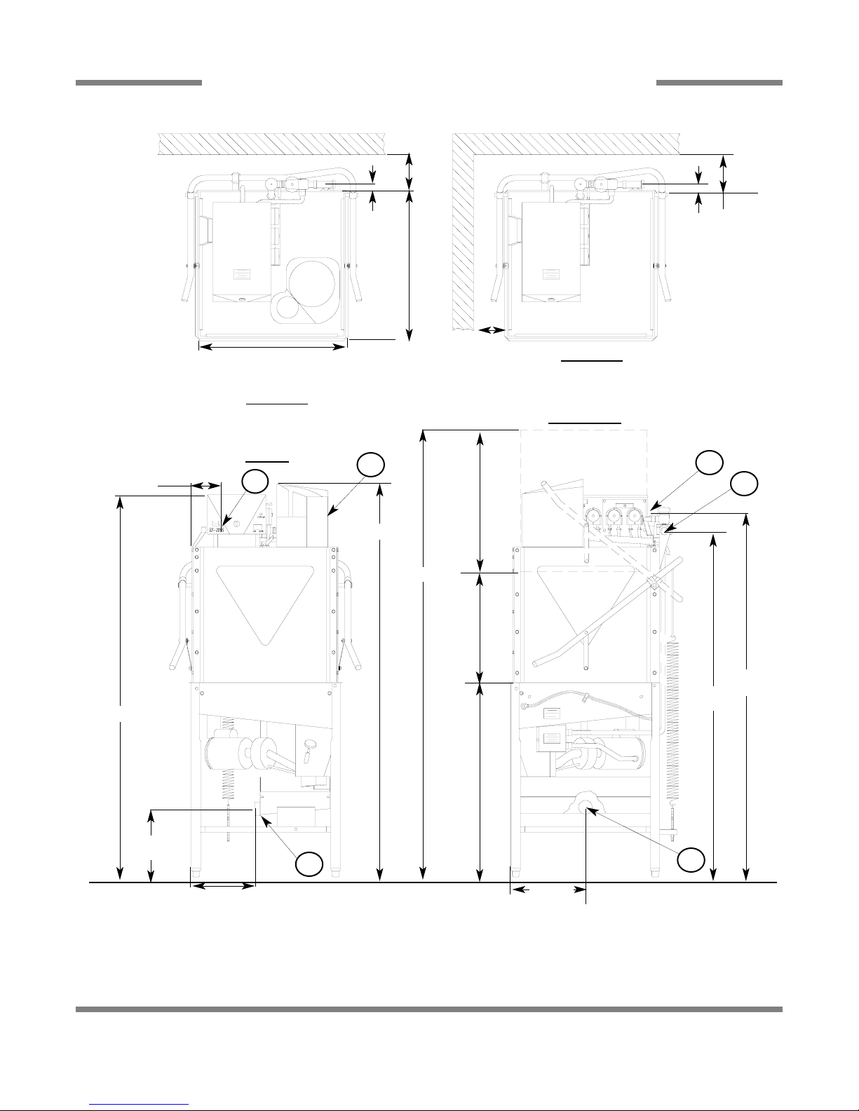
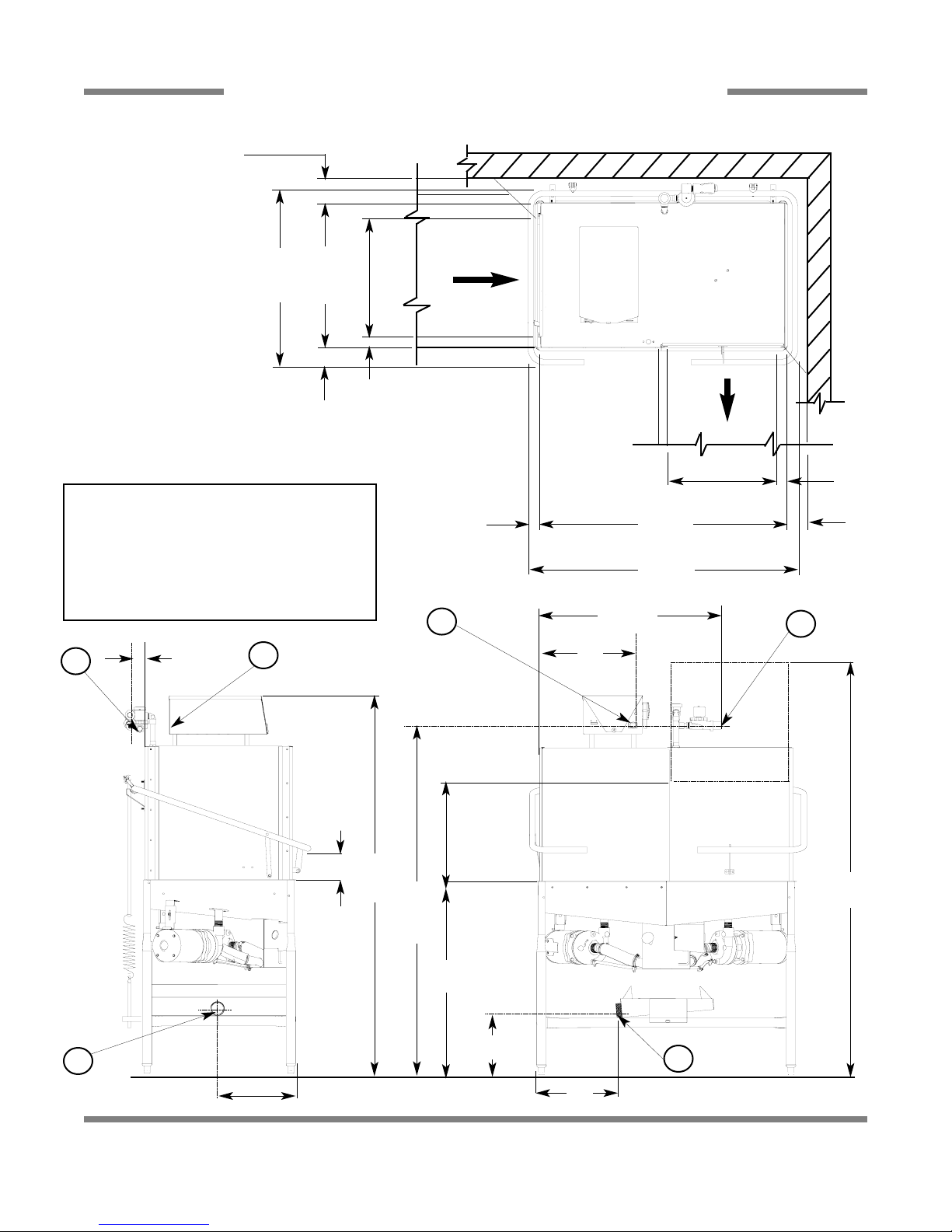
DIMENSIONS ES-2000/ES-2000XSP-PH
4
4” MIN.
ES-2000/XSP 25 1/4”
ES-2000XSP-PH 25 3/4”
TOP VIEW
RACK GUIDES IN STRAIGHT
THROUGH CONFIGURATION
5” MIN
TOP VIEW
RACK GUIDES IN CORNER
CONFIGURATION
12”
6”
24 1/4”
DOORS
19” MAX
CLEARANCE
34”
TABLE HEIGHT
1”
1”
11 1/2”
FRONT
RIGHT SIDE
NOTE: DRAIN IS ON FAR
SIDE OF ACCUMULATOR
4” MIN.
ES-2000/XSP 25 1/4”
ES-2000XSP-PH 30 3/4”
12 1/2”
A
B
D
B
A
C
61”
62”
A- DRAIN CONNECTION 2” NPT
B- ELECTRICAL CONNECTION 3/4” CONDUIT
C- WATER INLET 3/4” NPT
D- XSP DISPENSER
ALL DIMENSION FROM FLOOR ARE ADJUSTABLE +/1/2” DUE TO BULLET FEET.
64 1/4”
66 1/4”
77 1/4”
ES-2000 & ES-4000 Series Installation/Operation Manual 7610-011-35-10
Issued: 10-29-2007 Revised: N/A
SECTION 1: SPECIFICATION INFORMATION
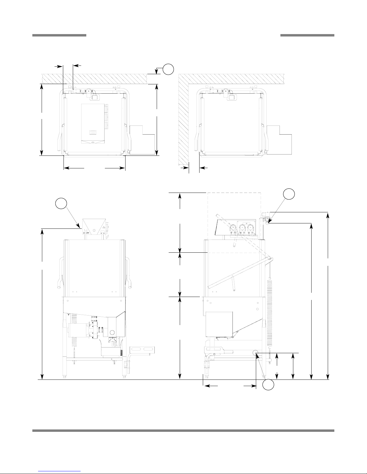
DIMENSIONS ES-2000-CS
5
LEGEND
A - WATER INLET (1/2”NPT)
B - ELECTRICAL CONNECTION POINT
C - DRAIN (2” NPT)
D - STANDARD CLEARANCE BETWEEN MACHINE AND
WALL (WITH DISHTABLE) IS 4”.
NOTE: All vertical dimensions are +/- 1/2” due to
adjustable feet.
5” Min.
4 11/16”
25 1/4”
25 1/4”
33 1/4”
Table
10 3/8”
11 3/4” with
Accumulator
Lift Kit
Ecolab No.:
96582202
64 11/16”
67 3/4”
22 1/2”
18”
Opening
62”
24 1/2”
Door
26 1/4”
A
B
C
D
ES-2000 & ES-4000 Series Installation/Operation Manual 7610-011-35-10
Issued: 10-29-2007 Revised: N/A
SECTION 1: SPECIFICATION INFORMATION
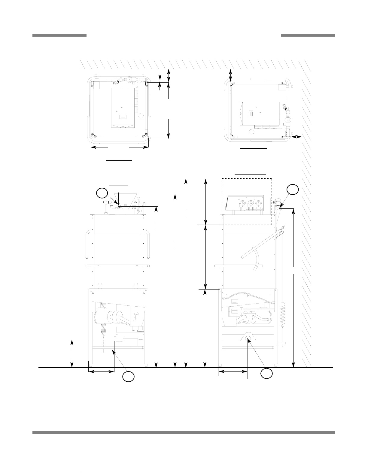
DIMENSIONS ES-2000HH
6
4” MIN.
TOP VIEW
RACK GUIDES IN STRAIGHT
THROUGH CONFIGURATION
5” MIN
TOP VIEW
RACK GUIDES IN CORNER
CONFIGURATION
12”
24 1/4”
DOORS
27” MAX
CLEARANCE
34”
TABLE HEIGHT
1”
11 1/2”
FRONT
RIGHT SIDE
NOTE: DRAIN IS ON FAR
SIDE OF ACCUMULATOR
4” MIN.
12 1/2”
A
B
A
C
72”
A- DRAIN CONNECTION 2” NPT
B- ELECTRICAL CONNECTION 3/4” CONDUIT
C- WATER INLET 3/4” NPT
ALL DIMENSION FROM FLOOR ARE ADJUSTABLE +/1/2” DUE TO BULLET FEET.
72”
77”
86”
25 1/4”
25 1/4”
ES-2000 & ES-4000 Series Installation/Operation Manual 7610-011-35-10
Issued: 10-29-2007 Revised: N/A
SECTION 1: SPECIFICATION INFORMATION
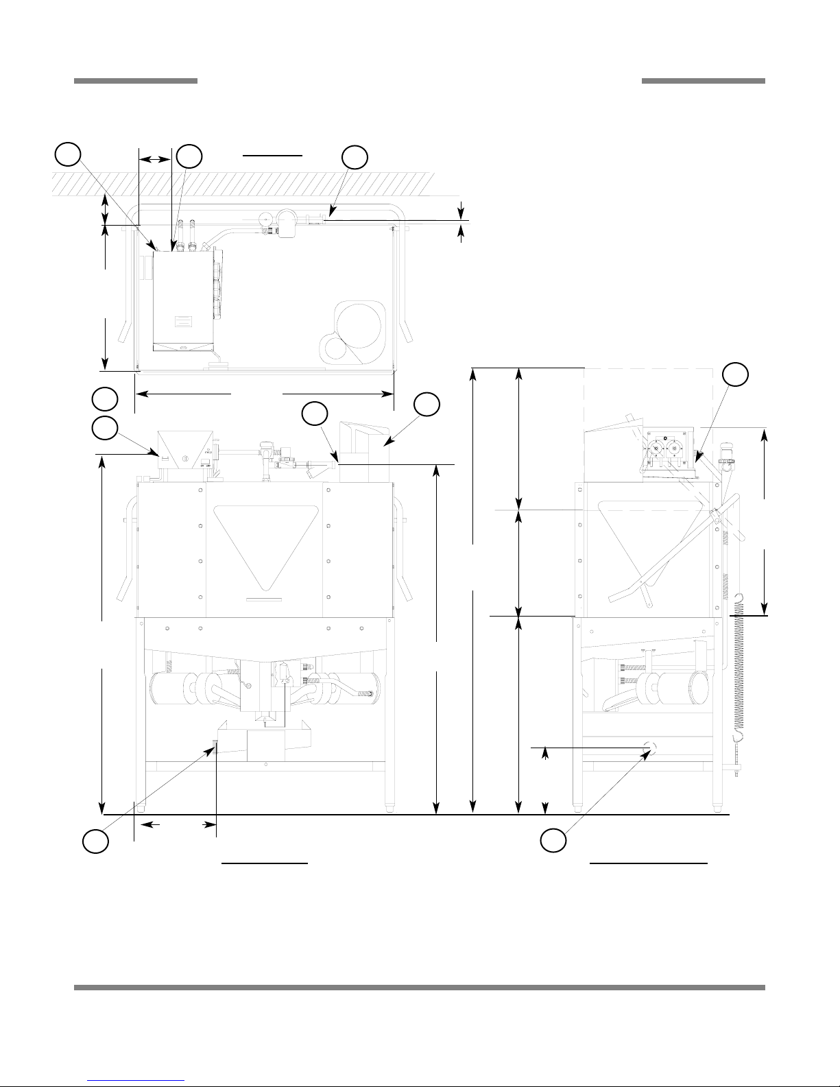
DIMENSIONS ES-4000/ES-4000XSP
7
TOP VIEW
FRONT VIEW RIGHT SIDE VIEW
A - DRAIN CONNECTION - 2” NPT
B - ELECTRICAL CONNECTION
C - WATER INLET - 3/4” NPT
D - SERVICE DISCONNECT SWITCH
E - XSP DISPENSER
ALL DIMENSION FROM FLOOR ARE ADJUSTABLE +/- 1/2”
DUE TO BULLET FEET.
25 7/8”
1”
60 1/2”
61”
10 1/2”
24 1/2”
DOORS
19” MAX
CLEARANCE
34”
TABLE HEIGHT
32 1/4”
44 1/8”
4” min.
4 3/4”
15 3/4”
C
C
E
B
D
B
A
A
D
D
75 3/4”

ES-2000 & ES-4000 Series Installation/Operation Manual 7610-011-35-10
Issued: 10-29-2007 Revised: N/A
SECTION 1: SPECIFICATION INFORMATION
DIMENSIONS ES-4000CDL
8
20 3/4”
OPENING
4 1/2”
MINIMUM
2 1/2”
1 1/2”
5”
19”
OPENING
20 3/4”
OPENING
2 1/2”
3 1/2”
4”
MINIMUM
2 1/2 “
A - DRAIN-GRAVITY 2” NPT
B - WATER INLET 3/4” NPT
C - ELECTRICAL CONNECTION 3/4”
ALL DIMENSION FROM FLOOR ARE
ADJUSTABLE +/- 1/2” DUE TO BULLET FEET.
32 3/4”
25 3/4”
43 1/2 “
46 1/2”
C
B
A
B
16”
13”
66 1/4”
60 3/4”
12”
34”
77”
14”
ES-2000 & ES-4000 Series Installation/Operation Manual 7610-011-35-10
Issued: 10-29-2007 Revised: N/A
SECTION 1: SPECIFICATION INFORMATION
DIMENSIONS ES-4000CDR
9
19”
OPENING
12 3/8”
2 1/2”
5”
2 1/2”
20 3/4”
OPENING
4 1/2”
MINIMUM
1 1/2”
20 3/4”
OPENING
2 1/2”
4”
MINIMUM
3 1/2”
A.- DRAIN-GRAVITY 2” NPT
B.- WATER INLET 3/4” NPT
C.- ELECTRICAL CONNECTION
ALL DIMENSION FROM FLOOR ARE
ADJUSTABLE +/- 1/2” DUE TO BULLET FEET.
32 3/4”
25 3/4”
43 1/2”
46 1/2”
30 1/2”
16”
C
C
B
B
A
A
77”
60 3/4”
66 1/4”
34”
12”
14”
ES-2000 & ES-4000 Series Installation/Operation Manual 7610-011-35-10
Issued: 10-29-2007 Revised: N/A
SECTION 1: SPECIFICATION INFORMATION
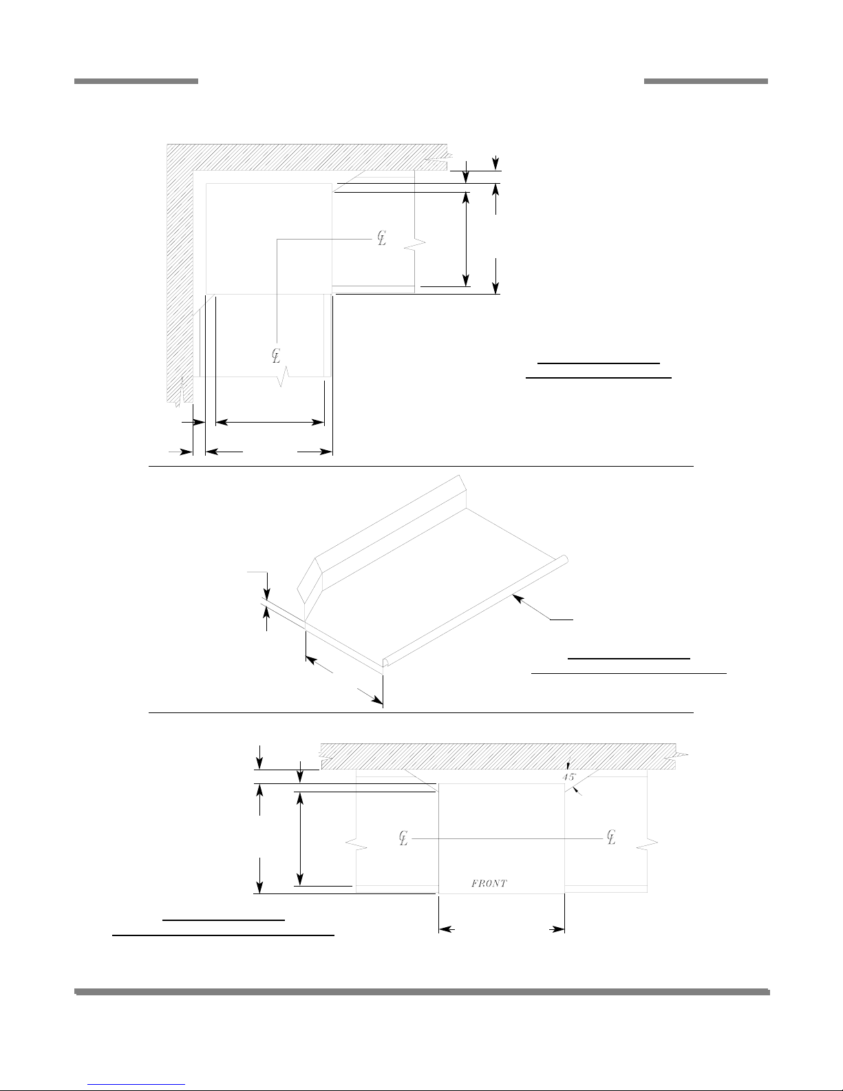
TABLE DIMENSIONS
10
TABLE DIMENSIONS
CORNER INST
ALLATION
T
ABLE DIMENSIONS
CONNECTION TO DISHMACHINE
T
ABLE DIMENSIONS
STRAIGHT THROUGH INSTALLATION
20 1/2”
OPENING
25 1/4”
2 1/4”
4” MIN.
2 1/2”
4”
MIN.
20 1/2”
OPENING
25 1/4”
20 1/2”
3/4”
1 1/2” ROLL
4”
MIN
2 1/2”
25 1/4”
20 1/2”
OPENING
25 1/4” ES-2000
30 3/4” XSP-PH
44” ES-4000

11
SECTION 2:
INSTALLATION/OPERATION
INSTRUCTIONS

VISUAL INSPECTION: Before inst alling the unit, check the container and machine for damage. Adamaged container is an indicator that there may be some damage to the machine. If there is damage to both the container and machine, do not throw away
the container. The dishmachine has been inspected and packed at the factory and is expected to arrive to you in new, undamaged condition. However, rough handling by carriers or others may result in there being damage to the unit while in transit. If
such a situation occurs, do not return the unit to Ecolab; instead, contact the carrier and ask them to send a representative to
the site to inspect the damage to the unit and to complete an inspection report. You must contact the carrier within 48 hours of
receiving the machine.
UNPACKING THE DISHMACHINE: Once the machine has been removed from the container, ensure that there are no missing parts from the machine. This may not be obvious at first. If it is discovered that an item is missing, contact Ecolab immediately to have the missing item shipped to you.
LEVEL THE DISHMACHINE: The dishmachine is designed to operate while being level. This is
important to prevent any damage to the machine during operation and to ensure the best results
when washing ware. The unit comes with adjustable bullet feet, which can be turned using a pair of
channel locks or by hand if the unit can be raised safely. Ensure that the unit is level from side to
side and from front to back before making any connections.
PLUMBING THE DISHMACHINE: All plumbing connections must comply with all applicable local, state, and national plumbing codes. The plumber is responsible for ensuring that the incoming water line is thoroughly flushed prior to connecting it to
any component of the dishmachine. It is necessary to remove all foreign debris from the water line that may potentially get
trapped in the valves or cause an obstruction.
CONNECTING THE DRAIN LINE: The drains for the ES-2000/ES-4000 dishmachines are gravity discharge. All piping from
the 2” MNPT connection on the waste accumulator must be pitched (1/4” per foot) to the floor or sink drain. All piping from the
machine to the drain must be a minimum 2” NPT and shall not be reduced. There must also be an air gap between the machine
drain line and the floor sink or drain. If a grease trap is required by code, it should have a flow capacity of 5 gallons per minute.
WATER SUPPLY CONNECTION: Ensure that you have read the section entitled “PLUMBING
THE DISHMACHINE” above before proceeding. Install the water supply line (3/4” pipe size minimum) to the dishmachine line strainer using copper pipe. It is recommended that a water shutoff valve be installed in the water line between the main supply and the machine to allow access
for service. The water supply line is to be capable of 20±5 PSI “flow” pressure at the recommended temperature indicated on the data plate.
NOTE: The optional Vapor Vent system must be connected to the COLD water line.
In areas where the water pressure fluctuates or is greater than the recommended pressure, it is suggested that a water pressure regulator be installed.
Do not confuse static pressure with flow pressure. Static pressure is the line pressure in a “no flow” condition (all valves and
services are closed). Flow pressure is the pressure in the fill line when the fill valve is opened during the cycle.
It is also recommended that a shock absorber (not supplied) be installed in the incoming water line. This prevents line hammer
(hydraulic shock), induced by the solenoid valve as it operates, from causing damage to the equipment.
PLUMBING CHECK: Slowly turn on the water supply to the machine after the incoming fill line and the drain line have been
installed. Check for any leaks and repair as required. All leaks must be repaired prior to placing the machine in operation.
ES-2000 & ES-4000 Series Installation/Operation Manual 7610-011-35-10
Issued: 10-29-2007 Revised: N/A
SECTION 2: INSTALLATION/OPERATION INSTRUCTIONS
INSTALLATION INSTRUCTIONS
12
Frame with Adjustable Foot
Raise
Lower
Incoming Plumbing Connection
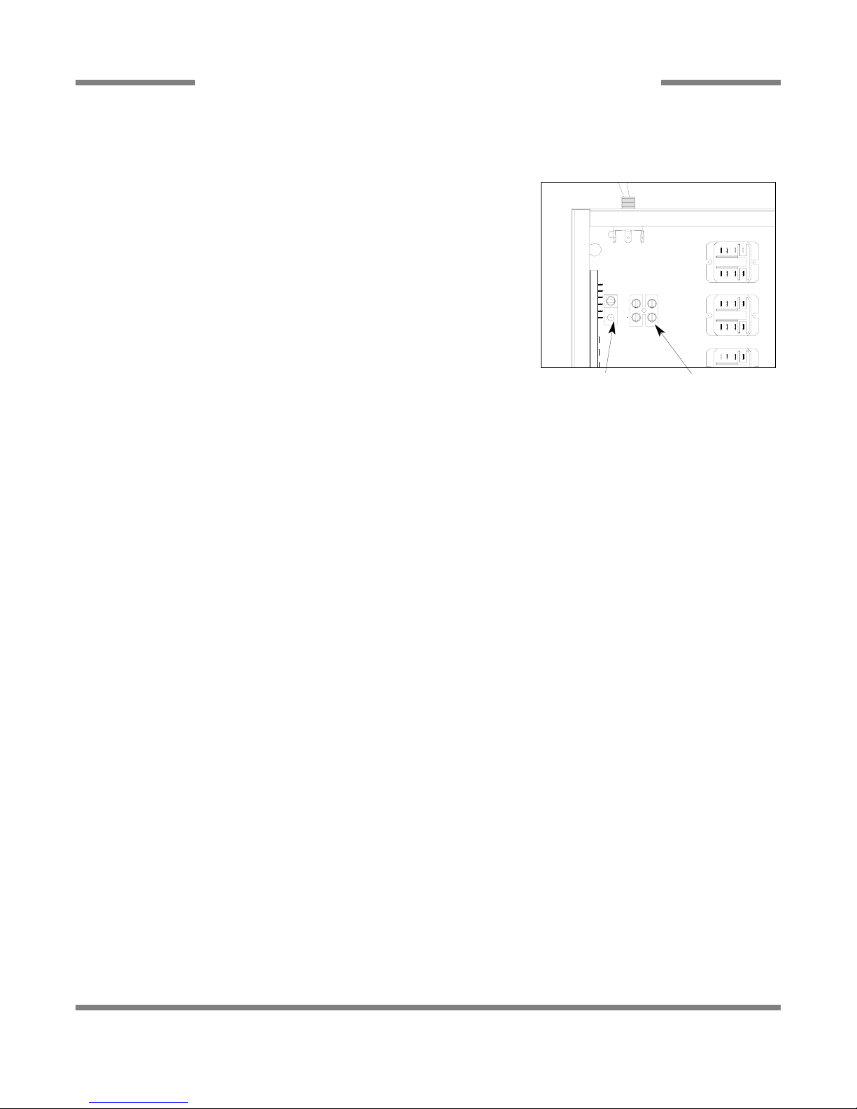
ELECTRICAL POWER CONNECTION: Electrical and grounding connections must comply with the applicable portions of the
National Electrical Code ANSI/NFPA 70 (latest edition) and/or other electrical codes.
Disconnect electrical power supply and place a tag at the disconnect switch to indicate that you are working on the circuit.
The dishmachine data plate is located on the right side and to the front of the
machine. Refer to the data plate for machine operating requirements, machine voltage, total amperage load and serial number.
To install the incoming power lines, unlock the control box. Install 3/4” conduit into
the pre-punched holes in the back of the control box. Route power wires and connect to power block and grounding lug. Install the service wires (L1 & L2) to the
appropriate terminals as they are marked on the terminal block. Install the grounding wire into the lug provided.
It is recommended that “DE-OX” or another similar anti-oxidation agent be used on
all power connections.
VOL TAGE CHECK: Ensure that the power switch is in the OFF position and apply power to the dishmachine. Check the incoming power at the terminal block and ensure it corresponds to the voltage listed on the data plate. If not, contact a qualified service agency to examine the problem. Do not run the dishmachine if the voltage is too high or too low. Shut of f the service breaker and mark it as being for the dishmachine. Advise all proper personnel of any problems and of the location of the service
breaker. Replace the control box cover and tighten down the screws.
ES-2000 & ES-4000 Series Installation/Operation Manual 7610-011-35-10
Issued: 10-29-2007 Revised: N/A
SECTION 2: INSTALLATION/OPERATION INSTRUCTIONS
ELECTRICAL INSTALLATION INSTRUCTIONS
13
Ground Lug
Power Block

PREPARATION: Before proceeding with start-up verify the following:
A. Sump strainer is in place.
B. Drain stopper is installed.
C. Check that the wash arms are securely screwed into the stationary bases and rotate freely. Also check that the end plugs
are securely screwed into the ends of all wash arms.
POWER UP: To energize electrically, proceed as follows:
A. Turn on electrical power supply at the circuit breaker.
B. Check voltage at incoming terminals L1& L2. The voltage measured at these points should match data plate voltage.
C. If voltages are in required range, close the control box cover.
TO FILL WASH TUB: To Fill Wash Tub depress the “On/Off/Fill” rocker switch to the “Fill” position and hold until you see water
draining out from the bottom of the machine. Open door for 3 seconds and close, this will start machine cycle. Allow machine
to complete one cycle, and then check for proper water level.
Note: Water must be in the sump while the machine is running to avoid running the pump dry and causing damage to the
pump seal.
If the water level is not at the level noted above it will require adjustment. Check to ensure that the recommended water pressure is being supplied to the machine (20 ±5 PSI is required). If the water pressure is correct then the fill valve cam will need
adjustment. Use the following steps to adjust the cam.
A. Turn power off at the machine circuit breaker.
B. Open control box cover
C. Locate the timer fill valve cam (Cam 4 from the timer motor)
D. Locate the spanner wrench taped to the electrical panel. The spanner wrench is used to adjust the cam.
E. To increase the water level, open the notch of the adjustable cam. To decrease the water level, close the notch. Care must
be taken that the set point does not extend into the home position of the timer. Do not move the side of the cam that starts the
fill; this will change the sequence of cycle operation.
F. With the door closed turn the power circuit breaker on. Open and close the door to run a cycle, then check the water level.
Adjust as necessary then close the control box cover.
Refer to page 21 for adjustment to the cam timer.
NOTE: The machine must run a complete cycle to drain and fill. If the machine is not allowed to drain, the water will build up
inside the tub. After the initial fill, the rinse water for the current cycle will become the wash water for the next cycle.
The dishmachine is now ready to proceed with the washing of dishes.
V APOR VENT OPTION: If the dishmachine is fitted with the optional vapor vent system, it will be shipped from the factory with
the vent option installed. Run several cycles to confirm that the vapor vent is functioning properly. At the end of the venting
sequence, there should be only a small amount of vapor released from the machine when the door interlock retracts and the
machine doors are opened.
ES-2000 & ES-4000 Series Installation/Operation Manual 7610-011-35-10
Issued: 10-29-2007 Revised: N/A
SECTION 2: INSTALLATION/OPERATION INSTRUCTIONS
OPERATING INSTRUCTIONS
14

WARNING: Certain materials, including silver, silver plate, aluminum and pewter, are attacked by sodium hypochlorite sanitizers (bleach).
PREP ARING DISHES: Preparation of the ware will help ensure good result s and less re-washes. If not done properly the dishes will not be clean and will reduce the efficiency of the dishmachine.
The following steps should be followed to ensure good results:
A. Remove all scraps and gross soil into a garbage can.
B. Separate and pre-soak silverware.
C. Separate and pre-soak the egg and casserole dishes.
D. Scrape all ware with a brush or spatula.
E. Flush cups, bowls and glasses with running water.
F. Prewash dishware by soaking or spraying with a pre-rinse hose.
G. Place dishes and cups in dish rack. Cups should be upside down (so they don’t hold water).
H. Place glasses and flatware in their respective racks. Scatter flatware loosely in rack. Glasses should be placed upside down
in a properly sized rack. For optimal results, flatware should be washed twice, the first being horizontal, the second in a special rack to hold flatware vertical.
DAILY MACHINE PREPARATION: Before proceeding with start-up, verify the following:
A. Open door and verify that the sump strainer is in place in the sump.
B. Verify that the drain stopper is in position.
C. Check that the plugs are securely screwed into the ends of all wash arms.
D. Check that the wash arms are securely screwed into the stationary bases and rotate freely.
E. Check levels in all chemical containers and replace if empty.
F. For initial fill, close doors then depress the “OFF/ON/FILL” rocker switch to the “FILL” position.
WASHING A RACK OF WARE:
A. Open doors, place a full rack into the machine, and close doors. Unit will start automatically.
B. After cycle is completed open doors and remove rack.
C. Place another full rack into the dishmachine, and close doors.
D. Dishmachine will repeat cycle.
SHUT DOWN AND CLEANING:
A. At the end of mealtime, move the “OFF/ON/FILL” switch to the “OFF” position.
B. Open doors and manually remove drain stopper to drain the unit.
C. Remove and clean upper and lower wash arms.
D. Remove and clean the sump strainer.
ES-2000 & ES-4000 Series Installation/Operation Manual 7610-011-35-10
Issued: 10-29-2007 Revised: N/A
SECTION 2: INSTALLATION/OPERATION INSTRUCTIONS
OPERATING INSTRUCTIONS (CONTINUED)
15

TO PREPARE PUMPS FOR OPERATION
The ES-2000/ES-4000 dishmachines are supplied with detergent, rinse additive and sanitizer dispensing chemical feeder
pumps. Locate the open ends of the chemical tubes with the tube stiffeners and place each one in the appropriate container.
A. Red Tubing = Detergent
B. Blue Tubing = Rinse Aid
C. White Tubing = Sanitizer
PRIMING PERISTALTIC PUMPS
Peristaltic pumps need priming when the machine is first installed or if for some reason the chemical lines have been removed
and air has been allowed to enter.
CAUTION: Water must be in the sump and wash tank prior to the dispensing of chemicals. Sanitizer in concentration is detrimental to the metal of the dishmachine and may cause damage without dilution.
1. Verify that the proper chemical tube stiffener inlet is in the proper container.
2. Use the toggle switches on the right side of control box to prime each pump. There are two (2) switches mounted by the
chemical feeder pumps. One will prime the sanitizer pump only, and the second will prime either the detergent or rinse aid
pump, depending upon which way it is depressed.
3. To prime the pumps, hold the switch in the momentary position until chemical can be observed entering the sump.
4. Detergent is dispensed as required during the wash cycle by the cam timer. The amount of detergent may need to be
increased or decreased depending on water quality and type of detergent. It is adjusted by changing Cam 6 on the cam timer.
5. Rinse additive is dispensed as required into the final rinse. The amount of rinse aid may need to be adjusted depending on
water hardness and results. It can be changed by changing Cam 7 on the cam timer.
6. Sanitizer, either chlorine or iodine, is dispensed into the final rinse. The amount of sanitizer may need to be adjusted depending on the concentration and type of sanitizer used. It is adjusted by changing Cam 5 on the cam timer.
WARNING: Some of the chemicals used in dishwashing may cause chemical burns if they come on contact with
your skin. Wear appropriate protective gear when handling these chemicals. If you do come in contact with these
chemicals flush the area with fresh water.
ES-2000 & ES-4000 Series Installation/Operation Manual 7610-011-35-10
Issued: 10-29-2007 Revised: N/A
SECTION 2: INSTALLATION/OPERATION INSTRUCTIONS
CHEMICAL DISPENSING EQUIPMENT
16
Machines that are equipped with the XSP package have a unique feature over other Ecolab models such as the ES-2000 or
ES-4000: the XSP machines use solid, rather than liquid detergent and rinse aid products (all machines use liquid sanitizing
agents). The solid product dispensing system is self-contained on top of all XSP units.
Operation of any dishmachine with the XSP dispenser is covered under the operational instructions found in this manual. The
solid detergent is automatically dispensed during the wash cycle. The machine will then dump the wash water, flush the tank,
and then should refill the tank with fresh water during the rinse cycle. The sanitizer and solid rinse aid are automatically dispensed during the rinse cycle.
Optimum dispensing control of the solid products has been achieved with this solid dispensing system. The detergent reservoir
has an indexing pedestal that keeps the product at a constant distance from the nozzle. The detergent pedestal is the major
reason why dispensing is very consistent from cycle to cycle. Another important feature which adds to the consistency of the
dispensing is the pressure regulators. Two dispenser pressure regulators are an integral part of the system. By closely regulating the feed water pressure to the products, uniform dispensing rates are achieved.
The solid detergent is available in 2 x 9 lb cases. the solid rinse aid is available in 3 x 0.75 lb cases. Both products have been
custom formulated for the unique operating characteristics of the XSP machine and dispensing system.
Dishmachines equipped with the XSP dispenser will have an overall height approximately 4-1/4” above the height of the control box, which is normally 66-1/4”. Machine width and table height are unaffected by the addition of the system.
The operating parameters and capacities of machines equipped with an XSP dispenser are not affected by the addition of the
system.
There are no special instructions for installing a unit equipped with an XSP dispenser.
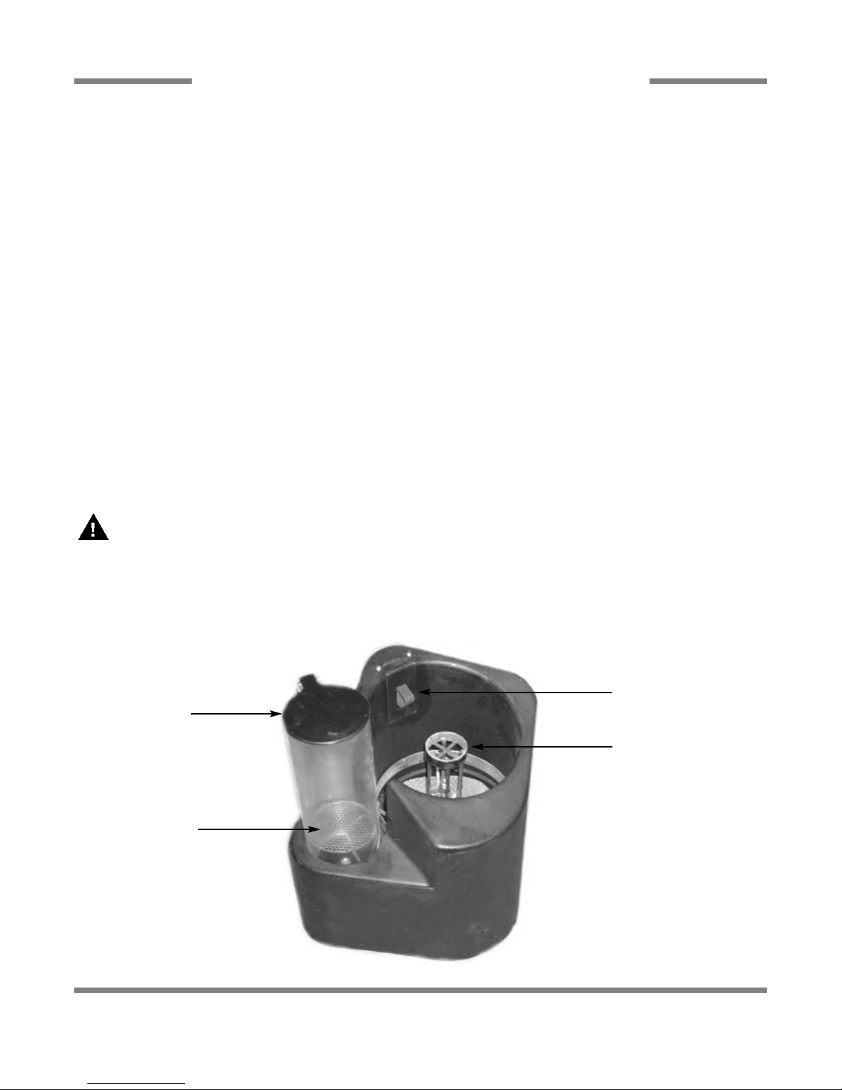
NOTE: DETERGENT SAFETY SWITCH MUST BE DEPRESSED FOR THE DISHMACHINE TO RUN!! (Refer to
Figure 1 below)
1. Remove the screw cap on the detergent capsule.
2. Invert the capsule holding on to the molded handle and place the detergent onto the pedestal.
3. Remove the snap lid on the rinse additive container and let the product fall onto the stainless steel screen in the Rinse
Additive Cylinder.
ES-2000 & ES-4000 Series Installation/Operation Manual 7610-011-35-10
Issued: 10-29-2007 Revised: N/A
SECTION 2: INSTALLATION/OPERATION INSTRUCTIONS
XSP DISPENSER PREPARATION
17
DETERGENT
SAFETY SWITCH
DETERGENT
PEDESTAL
RINSE
ADDITIVE
CYLINDER
STAINLESS
STEEL SCREEN

NOTE: THE SANITIZER CHEMICAL FEEDER PUMP REQUIRES PRIMING WHEN THE MACHINE IS FIRST
INSTALLED OR WHEN AIR ENTERS THE SANITIZER AGENT LINE. SANITIZER PUMPS ARE NORMALLY LOCATED ON THE LOWER HALF OF THE MACHINE AND THE PRIME SWITCH WILL BE NEARBY.
NOTE: WATER MUST BE IN THE SUMP AND WASH TANK PRIOR TO DISPENSING CHEMICALS. SANITIZER IN
ORIGINAL CONCENTRATION IS CAUSTIC AND MAY CAUSE DAMAGE TO THE WASH TANK AND/OR SUMP WITHOUT DILUTION.
DISPENSER SET-UP:
The following dispenser settings should be used as a starting point:
Detergent Product Feed Detergent Rinse-Aid Sanitizer
Dishmachine Titration Water Pressure Feed Time Feed Time Feed Time
ES-2000XSP(PH) 10 drops * 20 PSI 4 seconds 4 seconds 6 seconds
ES-4000XSP 10 drops * 20 PSI 6 seconds 6 seconds 11 seconds
* -Titrate 1
NOTE: These settings are only STARTING POINTS.
This system will require adjustment to meet the conditions of water temperature and softness at each account. If the water temperature is 160
°F or greater, it will require fewer seconds of feed time to get the same solid product usage.
EXAMPLE: If the feed water temperature is 170
°F the detergent and rinse aid feed times should be set to approximately
1 to 2 seconds. Please refer to the adjustment guidelines below as starting points to optimize the dispenser’s performance.
WATER PRESSURE SET-UP:
1. Adjust the primary water pressure regulator so that the pressure gauge reads approximately 20 PSI flow pressure while the
detergent is feeding. If the account’s flow pressure is less than 20 PSI, turn the adjustment knob on the regulator clockwise
until the pressure gauge indicates the maximum flow available.
SANITIZER FEED SET-UP:
1. Set the sanitizer feed to six seconds for the ES-2000XSP(PH) or eleven seconds for the ES-4000XSP. Adjust the sanitizer
cam timer so that the sanitizer pump begins feeding immediately after the rinse cycle starts (when pump motor starts).
2. Prime the sanitizer pump using the prime switch.
3. Run a complete cycle on the dishmachine.
4. Titrate the rinse water using the chlorine titration test kit. Chlorine titration should be between 50 and 100 ppm. Adjust the
cam timer if the chlorine level is not correct.
ES-2000 & ES-4000 Series Installation/Operation Manual 7610-011-35-10
Issued: 10-29-2007 Revised: N/A
SECTION 2: INSTALLATION/OPERATION INSTRUCTIONS
CHEMICAL SET-UP
18

1. Set the detergent feed time to four seconds for ES-2000XSP(PH), or six seconds for the ES-4000XSP. Adjust the detergent
cam timer so that the four or six second detergent spray begins immediately after the wash cycle starts.
2. Set the flush time (Detergent Flush cam) to 10 seconds. The flush must begin after the detergent feed spray and must end
at least five seconds before the machine drain opens.
3. Titrate wash water at the end of the wash cycle.
NOTE: Titration is a must. DO NOT neglect this step!
TITRATION PROCEDURES
1. Fill the titration vial to the 5 ml mark with wash solution.
2. Add 5 drops of Indicator P.
3. Titrate dropwise with Titrate 1 until the pink solution turns clear.
4. Add additional 1 or 2 drops of Indicator Pto make sure of the endpoint (Chlorine sanitizer can bleach out the Indicator P and
cause premature endpoint). Continue titrating with Titrate 1 until the pink color is gone.
ES-2000 & ES-4000 Series Installation/Operation Manual 7610-011-35-10
Issued: 10-29-2007 Revised: N/A
SECTION 2: INSTALLATION/OPERATION INSTRUCTIONS
DETERGENT SET-UP
19

1. Set rinse aid feed time to four seconds for the ES-2000XSP(PH) or six seconds for the ES-4000XSP. If the account has very
hot water temperature (160
°F or greater), use one or two seconds as a starting point instead of the normal four to six seconds.
Adjust the rinse aid cam timer so that the rinse aid spray begins immediately after the machine finishes filling with water.
2. Perform a sheeting test. Run a load with a set of glassware and a set of flatware.
NOTE: A new rinse aid capsule needs to be “wetted” before running a sheeting test. To wet the solid rinse aid,
run four or five cycles on the dishmachine. If the dishware does not sheet, try the following things in the order
given below:
a) Adjust the rinse aid feed time.
b) Adjust the feed water pressure.
NOTE: If the pressure is changed, the detergent titration will need to be rechecked.
c) Examine the rinse aid spray pattern. If necessary, clean and/or replace the spray nozzle.
3. Periodically , the consumption rate of the rinse aid product needs to be checked. After a minimum of two weeks, calculate the
number of racks washed per rinse aid capsule used. Do this by recording the count and taking inventory at each service call.
If the rinse aid usage is high (racks per capsule are low) and the dishware results are good (no spots), decrease the rinse aid
feed time. refer to the rinse aid consumption table below:
RINSE CONSUMPTION GUIDELINES
WATER HARDNESS
Food Soil Soft Medium Hard Very Hard
(0 - 4 gpg) (4 - 8 gpg) (8 - 12 gpg) (12 - 16 gpg)
Light 1400 1000 800 700
Medium 1200 900 600 500
Heavy 1000 600 400 300
(Racks per Capsule)
ES-2000 & ES-4000 Series Installation/Operation Manual 7610-011-35-10
Issued: 10-29-2007 Revised: N/A
SECTION 2: INSTALLATION/OPERATION INSTRUCTIONS
RINSE AID FEED SET-UP
20

The ES-2000/ES-4000 cam timer is a 1 minute, 30 second, 8-cam timer that controls the operation of the dishmachine. The following is a description of the set points for each cam and the function of each switch. NOTE: The ES-2000-V has an additional
time circuit which adds 30 seconds to the end of the cycle.
CAM 1: Cam 1 is a cut cam with a single notch and serves as the cycle/reset control.
FUNCTION: When the machine is in the operation mode the notch is the home position. The machine will remain idle until the door
is opened, then cam 1 moves to the start position and holds until the door is closed. The closing of the door will start the next cycle.
The cam will rotate a complete cycle, and return to the home position and hold.
CAM 2: Cam 2 is a cut cam and provides the wash cycle timing.
FUNCTION: The wash cam works off the normally open contacts of Cam 2. This requires the switch be held closed by the cam.
It will close and energize the wash pump 2 seconds after the cycle switch is activated. The pump will operate through the wash
cycle (40 seconds) then shut down for the dwell period (20 seconds). As the cam rotates it energizes the pump for the rinse cycle
(25 seconds). When cam 1 reaches it’s home position it will de-energize cam 2, shutting down the wash pump.
NOTE: The last 6 cams are adjustable. The following instructions will require that the timer position have the cams to the
front and the motor to the left.
CAM 3: Cam 3 is an adjustable cam and controls the drain solenoid.
FUNCTION: The drain solenoid works off the normally closed contacts of cam 3. When the cycle is initiated, the micro switch will
be held open until it is allowed to drop into the notch of the cam. This energizes the drain solenoid which drains the machine. Af ter
a 12 second delay the cam reverses the micro switch, de-energizing the drain solenoid. This cam may require adjusting due to
varying water pressure. The drain solenoid must remain open long enough to remove whatever water the fill valve solenoid allows
in the machine.
SETTINGS: The right side of cam 3 must be set to pick up the switch arm just before the wash/rinse cycle cam switch drops. It
will hold the drain solenoid open to drain all the water in the tank from the unit during the dwell period. Any adjustment made to
the drain should be made to the left side of cam 3. The cam must be moved back into the wash time until all of the water is drained
from the machine.
CAM 4: Cam 4 is an adjustable cam and controls the fill valve and therefore the rinse cycle.
FUNCTION: The fill valve cam works off the normally closed contacts of cam 4. This requires the switch to be held open by the
cam and allowed to drop into the notch to operate the fill valve. This energizes the fill solenoid which opens to fill the machine with
fresh water. After a 10 second delay, the cam reverses the micro switch, de-energizing the fill solenoid. The fill cam may require
adjustment due to varying water pressure. The fill solenoid must remain open a sufficient length of time to fill the machine to the
correct level.
SETTINGS: The right side of cam 4 must be set to allow the switch arm to drop 2 seconds before the drain solenoid is de-energized which flushes the detergent residue from the unit. It will hold the fill solenoid open until the cam switch arm is raised. At that
time the fill solenoid is de-energized, shutting off the incoming water. The tub will be filled to the correct level to rinse the rack.
Any adjustment made to the timing of the fill solenoid should be made with the left side of cam 4. To increase the water level, open
the notch of the cam and for decreasing the level of the notch should be closed.
CAM 5: Cam 5 is an adjustable cam and controls the sanitizer pump.
FUNCTION: The sanitizer pump cam works off the normally closed contacts of cam 5. This requires the switch arm to be held
open by the cam and allowed to drop into the notch to operate the pump. The time that the sanitizer pump will remain energized
must be determined in the field to suit the chemical used and water conditions.
SETTINGS: The left side of cam 5 must be set to allow the switch arm to drop in past the starting point of the fill cam and after
the drain solenoid has closed. The adjustment for sanitizer volume must be made with the right side of the cam. To increase the
volume the notch should be increased or to decrease the amount of sanitizer the notch should be closed slightly in increments until
the correct level is reached.
ES-2000 & ES-4000 Series Installation/Operation Manual 7610-011-35-10
Issued: 10-29-2007 Revised: N/A
SECTION 2: INSTALLATION/OPERATION INSTRUCTIONS
CAM TIMER OPERATION (ES-2000/ES-4000)
21

CAM 6: Cam 6 is an adjustable can and controls the detergent pump.
FUNCTION: The detergent pump cam works off the normally closed contacts of cam 6. This requires the switch arm to be held
open by the cam and allowed to drop into the notch to operate the pump. The time that the detergent pump will remain energized
must be determined in the field to suit the chemical used and water conditions.
SETTINGS: The left side of cam 6 must be set to drop in past the starting point of the wash pump cam. The adjustment for dete rgent volume must be made with the right side of the cam. To increase the volume, the notch should be increased or to decrease
the amount of detergent the notch should be closed slightly in increments until the correct level is reached.
CAM 7: Cam 7 is an adjustable cam and controls the rinse aid pump.
FUNCTION: The rinse aid pump cam works off the normally closed contacts of cam 7. This requires the switch arm to be held
open by the cam and allowed to drop into the notch to operate the pump. The time that the rinse aid pump will remain energized
must be determined in the field to suit the chemical used and water conditions.
SETTINGS: The left side of cam 7 must be set to drop in past the starting point of the fill cam and after the drain solenoid has
closed. The adjustment for rinse aid volume must be made with the right side of the cam. To increase the volume the notch should
be increased or to decrease the amount of detergent the notch should be closed slightly in increments until the correct level is
reached.
CAM 8: Cam 8 is an adjustable cam and is not used.
ES-2000 & ES-4000 Series Installation/Operation Manual 7610-011-35-10
Issued: 10-29-2007 Revised: N/A
SECTION 2: INSTALLATION/OPERATION INSTRUCTIONS
CAM TIMER OPERATION (ES-2000/ES-4000) (CONTINUED)
22
 Loading...