

INSTALLATION MANUAL
IN-SPECEIL012.R2
SP-CEIL-012
InFocus Corporation
27700B S.W. Parkway Ave.
Wilsonville, OR 97070-9215
1-800-294-6400
www.infocus.com

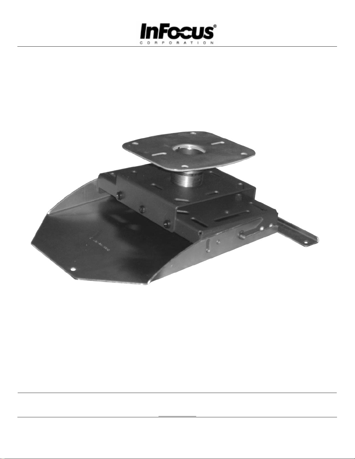
PBL-110 Projector Mount
Page - 2 - Installation Manual

SP-CEIL-012
Table of Contents
Warning Statements............................................................................................................................................- 4 -
Parts List .............................................................................................................................................................- 5 -
Installation Tools ................................................................................................................................................- 5 -
Ceiling and Wall Installation..............................................................................................................................- 6 -
Adjustable Height ...............................................................................................................................................- 7 -
Adjustments and Extension Arm........................................................................................................................- 8 -
Mount Installation...............................................................................................................................................- 9 -
Troubleshooting Procedures .............................................................................................................................- 11 -
Technical Specifications...................................................................................................................................- 12 -
Warranty ...........................................................................................................................................................- 13 -
Contact InFocus Corporation............................................................................................................................- 13 -
Notes.................................................................................................................................................................- 14 -
Installation Manual Page - 3 -
Warning Statements
WARNING:
WARNING:
WARNING:
THE CEILING STRUCTURE MUST BE CAPABLE OF SUPPORTING AT LEAST FIVE (5) TIMES
THE WEIGHT OF THE PROJECTOR. IF NOT, THE CEILING MUST BE REINFORCED. PROPER
INSTALLATION PROCEDURE BY A QUALIFIED SERVICE TECHNICIAN, AS OUTLINED IN THE
INSTALLATION INSTRUCTIONS, MUST BE ADHERED TO. FAILURE TO DO SO COULD RESULT
IN SERIOUS PERSONAL INJURY, OR EVEN DEATH.
SAFETY MEASURES MUST BE PRACTICED AT ALL TIMES DURING THE INSTALLATION OF
THIS PRODUCT. USE PROPER SAFETY GEAR AND TOOLS FOR THE INSTALLATION
PROCEDURE TO PREVENT PERSONAL INJURY.
PRIOR TO THE INSTALLATION OF THIS PRODUCT, THE INSTALLATION INSTRUCTIONS
SHOULD BE READ AND COMPLETELY UNDERSTOOD. THE INSTALLATION INSTRUCTIONS
MUST BE READ TO PREVENT PERSONAL INJURY AND PROPERTY DAMAGE. KEEP THESE
INSTALLATION INSTRUCTIONS IN AN EASILY ACCESSIBLE LOCATION FOR FUTURE
REFERENCE.
Indicates that the power plug is to be
disconnected from the power outlet.
Safety precautions must be taken at all
Contact InFocus Corporation with any
questions.
times.
Warning and Caution statements.
A secure structure must support the weight, or load, of the projector. When mounting to a ceiling
that contains wooden studs, dead center of the wooden stud must be confirmed prior to
installation.
Do not install on a structure that is prone to vibration, movement or chance of impact. Failure to
do so could result in damage to the projector and/or damage to the mounting surface.
Do not install near heater, fireplace, direct sunlight, air conditioning or any other source of direct
heat energy. Failure to do so may result in damage to the projector and could increase the risk of
fire.
At least two qualified people should perform the installation procedure. Injury and/or damage can
result from dropping or mishandling the projector.
Recommended mounting surfaces: wooden studs and solid-flat concrete. If the mount is to be
installed on any surface other than wooden studs, use suitable hardware (which is commercially
available).
SP-CEIL-012
Page - 4 - Installation Manual
SP-CEIL-012
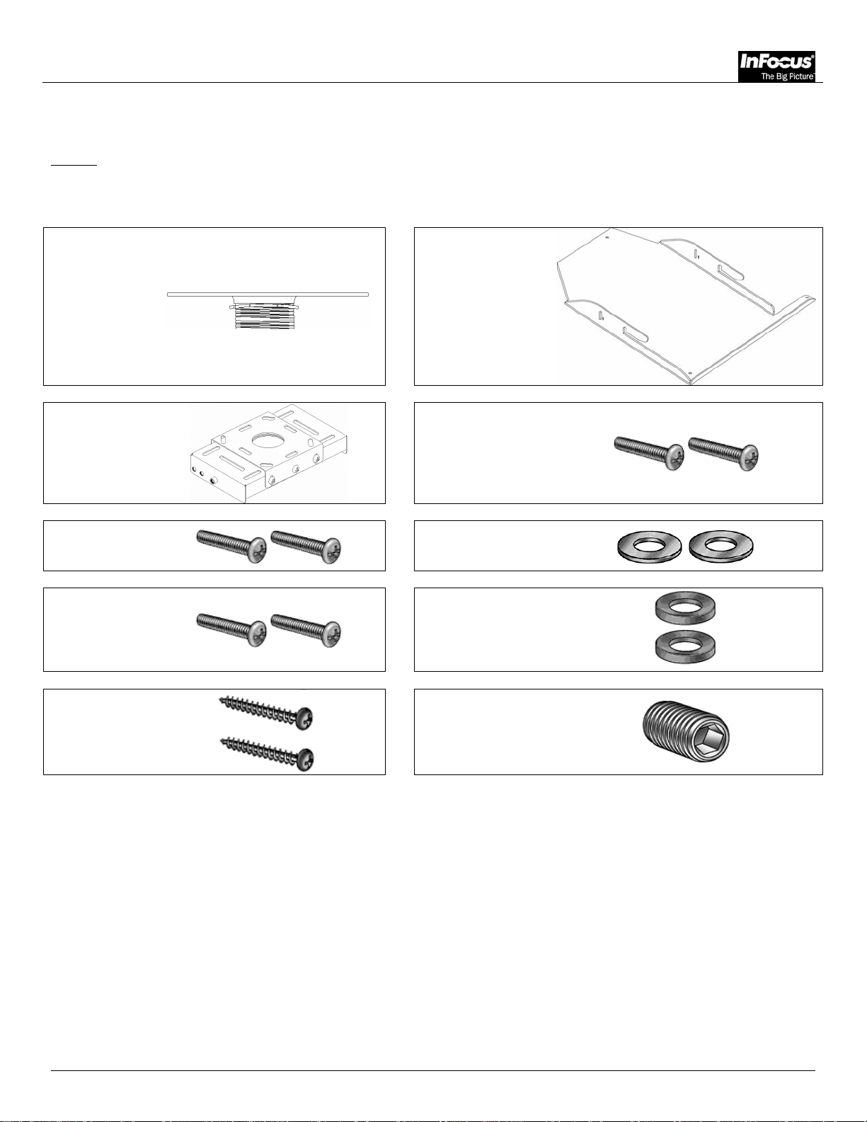
Parts List
NOTE: This mount is shipped with all proper installation hardware and components. Make sure that none
of these parts are missing and/or damaged before beginning installation. If there are parts missing
and/or damaged, please stop the installation and contact InFocus Corporation (800-294-6400).
SP-CEIL-012
Ceiling Bracket
(Qty 1)
PBM-757 (Qty 1)
PBB-10RL Base
Box (Qty 1)
M6 x 12mm
Phillips Head
Screws (Qty 3)
M6 x 12mm
Angle Locking
Screws (Qty 2)
#14 Wood
Screws (Qty 2)
M6 x 12mm Hinge
Pin Screws (Qty 2)
Flat Washers (Qty 2)
Conical Spacers
(Qty 2)
M5 Set Screw (1ea)
Installation Tools
Phillips Head Screw Driver Portable Drill
Soft Material/ Blanket Pencil
1/8” Drill Bit Level
Tape Measure M5 Allen Wrench
Ladder
Installation Manual Page - 5 -
SP-CEIL-012
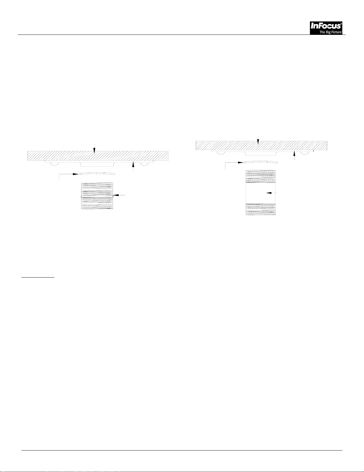
Ceiling and Wall Installation
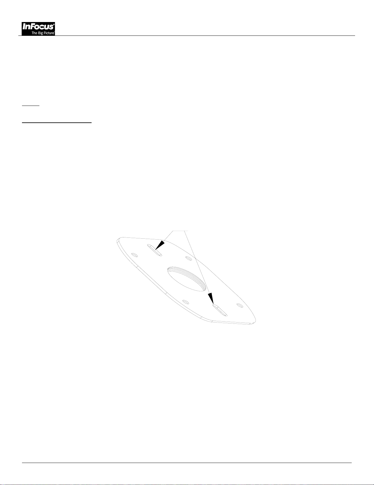
Unpack the Gyrolock® and review any WARNING statements that apply to the installation. Select the desired
location for the Gyrolock
points for a solid structure installation.
NOTE
: Pre-drill all holes (pilot hole – 1/8” drill bit).
Single Stud Installation
1. Locate the center of the single stud where the Gyrolock
points for this installation must be used. Use a stud finder to locate the stud that will be used to mount
the PBL (ceiling or wall). It is advised that all holes be pre-drilled with a 1/8” drill bit.
2. Secure the upper plate to the single stud with the two (2) #14 wood screws (supplied).
3. Start to secure the plate to the outer mounting points first. The plate may travel ½" front to back from
center.
4. Secure the final wood screw to the center of the upper plate (Figure 1).
®
. There are three mounting points for a single stud installation and four mounting
®
will be installed. The two (2) center mounting
SINGLE STUD
Figure 1. Single Stud Installation
Page - 6 - Installation Manual
SP-CEIL-012
Adjustable Height
1. Screw the fully threaded nipple all the way into the secured top plate. Use the jam screw (supplied) to
secure the pipe (Figure 2).
2. Screw the PBC coupling all the way onto the threaded nipple or (optional) 1-1/2" pipe and secure the M6
x 12 Phillip screw (Figure 3).
CEILING STRUCTURE
CEILING STRUCTURE
TOP PLATE
TOP PLATE
JAM NUT
1-1/2 NIPPLE
JAM NUT
(OPTIONAL LENGTH)
1-1/2 NIPPLE
WARNING:
Figure 2. Height Adjustment Figure 3. PBL Positioning
Make sure you don’t remove the two (2) 8mm screws completely from the extension column
when adjusting the height. Failure to do so may result in personal injury and damage to the
projector. Simply loosen, adjust and tighten screws.
Installation Manual Page - 7 -

Adjustments and Extension Arm
SP-EXTARM-01
SP-EXTARM-02
SP-EXTARM-03
SP-EXTARM-04
Contact InFocus for extensions.
Adjustments
• Roll & pitch greater than ± 20° from center.
• Quick positive release with positive security lock.
• 360° yaw.
• Cables can be routed inside the adjustable column of 1.5” piping.
SP-CEIL-012
JAM NUT
TOP PLATE
(OPTIONAL)
1-1/2 (NTP) PIPE
Figure 4. Extensions Pipe (Optional)
Page - 8 - Installation Manual
SP-CEIL-012
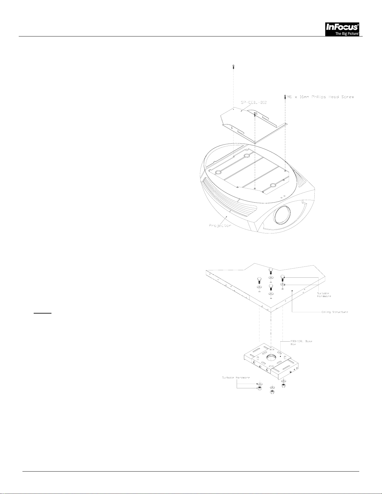
Mount Installation
1. Invert the projector and place it on a soft and flat
surface. Locate the three (3) 6 (mm) mounting
points found on the bottom of the projector.
2. Secure the mounting bracket using the three (3) 6
(mm) x 12 (mm) Phillip Head screws (supplied).
3. Do not over tighten the screws!
1. Install the base box securely to the ceiling
structure in accordance with proper commercial
standards. Use (commercially available) suitable
hardware depending on the installation
requirements.
NOTE
: If an extension adapter is to be used,
InFocus has a variety of different
adapters that can be purchased. Please
contact Customer Service.
Figure 5
Figure 6
Installation Manual Page - 9 -

1. Install the two (2) conical spacers and two (2)
flat washers two, (2) hinge pin screws loosely
on both sides of the base box.
2. Raise the projector with the mounting bracket
attached and slip though the hinge pin slots
openings on the bracket into the base box.
3. Install the two (2) angle locking screws adjust
the angle, lock it, and then tighten the hinge
pin screws.
SP-CEIL-012
1. Check all the hardware for proper tightness and
security. Do not over tighten hardware.
1. Install the two (2) conical spacers and two (2)
flat washers, two (2) hinge pin screws loosely
on both sides of the base box.
2. Raise the projector with the mounting bracket
attached and slip though the hinge pin slots
openings on the bracket into the base box.
3. Install the two (2) angle locking screws adjust
the angle, lock it, and then tighten the hinge
pin screws.
Figure 7
Figure 8
Page - 10 - Installation Manual

SP-CEIL-012
Troubleshooting Procedures
QUESTION: My projector mount must be set at an angle to be viewed properly on the wall, but the
projector will not hold at this position. Why is this?
ANSWER: The angle adjustments are not tight; they must be tightened.
QUESTION: Why won’t my bracket fit my projector?
ANSWER: There may be several mounting positions for your particular bracket. Try to line up the
holes on the bracket with the mounting points on the projector. If this still does not
solve the problem, then contact Customer Service and advise them of the situation.
Installation Manual Page - 11 -

Technical Specifications
6.00
4.50
SP-CEIL-012
6.75
4.50
Figure 5. Technical Dimensions
Page - 12 - Installation Manual

SP-CEIL-012
Warranty
Limited Lifetime Warranty
All products carry a limited lifetime warranty from ship date against defects in materials and workmanship.
InFocus Corporation is not liable for improper installation that results in damage to mounts, adapters, display
equipment or personal injury.
Contact InFocus Corporation
In the event of missing and/or damaged equipment, or technical questions, the following information can
help in the completion of the installation.
Customer Service – (800) 294-6400
Installation Manual Page - 13 -

Notes
SP-CEIL-012
InFocus Corporation
27700B S.W. Parkway Ave.
Wilsonville, OR 97070-9215
1-800-294-6400
www.infocus.com
Page - 14 - Installation Manual
IN-SPECEIL012.R2
 Loading...