

Page 1

PROD. NO. 011423
MOD. NO. SPT190
1/2" Variable Speed Router Kit
Operator’s Manual (p.2)
Trousse de toupie plongeante de 1/2 po à
vitesse variable
Manuel de l’utilisateur (p.12)
SAVE THIS MANUAL
You will need this manual for safety instructions, operating procedures,
and warranty. Put it and the original sales invoice in a safe, dry place for
future reference.
CONSERVEZ CE GUIDE
Vous aurez besoin de ce guide pour les instructions de sécurité, les
procédures d’utilisation et la garantie. Conservez-le dans un endroit sûr et
sec pour référence future.
v.081118
Page 2

IMPORTANT SAFETY INSTRUCTIONS
WARNING: When using electric tools, machines or equipment, basic safety precau-
tions should always be followed to reduce the risk of re, electric shock, and
personal injury.
READ ALL INSTRUCTIONS BEFORE USING THIS TOOL
1. KEEP WORK AREA CLEAN. Cluttered areas invite injuries.
2. CONSIDER WORK AREA ENVIRONMENT. Don’t use power tools in damp,
wet, or poorly lit locations. Don’t expose your tool to rain. Keep the work area
well lit. Don’t use tools in the presence of ammable gases or liquids.
ENGLISH
3. KEEP CHILDREN AND BYSTANDERS AWAY. All children should be kept away
from the work area. Don’t let them handle machines, tools, or extension cords.
Visitors can be a distraction and are difcult to protect from injury.
4. GROUNDED TOOLS must be plugged into an outlet that itself is properly
installed and grounded. Grounding provides a low-resistance path to carry
electricity to ground away from the operator, should the tool malfunction electrically. Do not remove the grounding prong from the plug or alter the plug in
any way. If in doubt as to whether the outlet is properly grounded according to
code, check with a qualied electrician.
5. OBSERVE PROPER PRECAUTIONS REGARDING DOUBLE INSULATION.
This tool is double insulated. It is equipped with a polarized plug. One blade
is wider than the other, so it will t into a polarized outlet only one way. If you
have difculty inserting the plug, try reversing it. If it still doesn’t t , do not alter
the plug; have a qualied electrician install a polarized outlet.
6. GUARD AGAINST ELECTRIC SHOCK. Prevent body contact with grounded
surfaces: pipes, radiators, ranges, and refrigerator enclosures. When your body
is grounded the risk of electric shock increases. When working wherever “live”
electrical wires may be encountered, try to ascertain whether there is a danger
of shock. Even so, DO NOT TOUCH ANY METAL PARTS OF THE TOOL while
using it. Hold the tool only by the plastic grip to prevent electric shock if you
contact a live wire.
7. DO NOT ABUSE THE CORD. Never carry your tool by the cord or pull on the
cord to unplug it. Protect the cord from potential sources of damage: heat, oil &
solvents, sharp edges, or moving parts. Replace damaged cords immediately.
8. WHEN WORKING OUTDOORS, USE AN OUTDOOR-RATED EXTENSION
CORD. An extension cord rated for outdoor use must be marked “W-A” or “W”.
9. DO NOT EXPOSE ELECTRICAL POWER TOOLS TO MOISTURE. Rain or
wet conditions can cause water to enter the tool and lead to electric shock.
10. ENSURE THE EXTENSION CORD YOU USE IS OF SUFFICIENT GAUGE
FOR ITS LENGTH.
Recommended Minimum Wire Gauge for Extension Cords
Amps from
Tool Nameplate
0 - 5 amps 16 ga. 16 ga. 16 ga. 14 ga. 12 ga. 12 ga.
5.1 - 8 amps 16 ga. 16 ga. 14 ga. 12 ga. 10 ga. Do Not Use
8.1 - 12 amps 14 ga. 14 ga. 12 ga. 10 ga. Do Not Use Do Not Use
12.1 - 15 amps 12 ga. 12 ga. 10 ga. 10 ga. Do Not Use Do Not Use
15.1 - 20 amps 10 ga. 10 ga. 10 ga. Do Not Use Do Not Use Do Not Use
25' long 50' long 75' long 100' long 150' long 200' long
11. STORE IDLE EQUIPMENT. Store equipment in a dry area to inhibit rust. Equip-
ment also should be in a high location or locked up to keep out of reach of
children.
12. DON’T FORCE THE TOOL.
It will do the job better and more safely at the rate
for which it was intended.
13. USE THE RIGHT TOOL. Don’t force a small tool or attachment to do the work
of a larger industrial tool. Don’t use a tool for a purpose for which it was not
intended.
2
Page 3

IMPORTANT SAFETY INSTRUCTIONS
14. DRESS PROPERLY. Don’t wear loose clothing or jewelry; they can be caught in
moving parts. Protective, non-electrically conductive gloves and non-skid footwear are recommended when working. Wear protective hair covering to contain
long hair and keep it from harm.
15. USE EYE PROTECTION. Use a full-face mask if the work you’re doing produces metal lings, dust or wood chips. Goggles are acceptable in other situations.
Wear a clean dust mask if the work involves creating a lot of ne or coarse
dust.
16. SECURE WORK. Use clamps or a vise to hold the work. It’s safer than using
your hands and it frees both hands to operate the tool.
17. DON’T OVERREACH. Keep proper footing and balance at all times. Do not
reach over or across machines that are running.
18. MAINTAIN TOOLS WITH CARE. Keep tools sharp and clean for better and
safer performance. Follow instructions for lubricating and safe performance.
Follow instructions for lubricating and changing accessories. Keep handles dry,
clean and free from oil and grease.
19. AVOID UNINTENTIONAL STARTING. Be sure the switch is in the OFF position
before plugging in.
20. ALWAYS CHECK AND MAKE SURE TO REMOVE ANY ADJUSTING KEYS
OR WRENCHES before turning the tool on. Left attached, these parts can y
off a rotating part and result in personal injury.
21. DO NOT USE THE TOOL IF IT CANNOT BE SWITCHED ON OR OFF. Have
your tool repaired before using it.
22. DISCONNNECT THE PLUG FROM POWER BEFORE MAKING ANY
ADJUSTMENTS. Changing attachments or accessories can be dangerous if
the tool could accidentally start.
23. STAY ALERT. Watch what you are doing & use common sense. Don’t operate
any tool when you are tired.
24. CHECK FOR DAMAGED PARTS. Before using this tool, any part that is damaged should be carefully checked to determine that it will operate properly and
perform its intended function. Check for alignment of moving parts, binding
of moving parts, breakage of parts, mountings, and other conditions that may
affect its operation. Inspect screws and tighten any ones that are loose. Any
part that is damaged should be properly repaired or replaced by an authorized
service center unless otherwise indicated elsewhere in the instruction manual.
Have defective switches replaced by an authorized service center. Don’t use
the tool if switch does not turn it on and off properly.
25. REPLACEMENT PARTS. When servicing, use only identical replacement parts.
26. SERVICE AND REPAIRS should be made by qualied repair technicians at an
authorized repair centre. Improperly repaired tools could cause serious shock
or injury.
ENGLISH
SAFETY INSTRUCTIONS FOR ROUTERS
n HANDLE ROUTER BITS WITH CARE. The tungsten carbide cutters are
especially brittle.
n BEFORE OPERATION, examine each bit carefully for chips, cracks, or
damage. Replace the bit if a aw is found.
n AVOID CUTTING INTO NAILS. Check the workpiece to make sure it’s free
of nails.
n HOLD THE ROUTER IN BOTH HANDS WITH A FIRM, TIGHT GRIP.
n ALWAYS KEEP YOUR HANDS AWAY FROM THE ROTATING
COMPONENTS.
n MAKE SURE THAT THE BIT DOES NOT TOUCH ANY WORKPIECE
BEFORE SWITCHING ON THE TOOL.
n RUN THE ROUTER IDLE FOR A WHILE BEFORE CONTACTING THE
WORKPIECE, and watch for any wobble of the bit caused by improper
installation.
3
Page 4

SAFETY INSTRUCTIONS FOR ROUTERS
n KEEP IN MIND THE ROTATION DIRECTION OF THE ROUTER BIT AND THE
WAY YOU FEED IT IN.
n DON’T LEAVE THE ROUTER RUNNING UNATTENDED.
n DO NOT TOUCH THE BIT RIGHT AFTER USE. It will be very hot and can burn
your skin.
n REMOVE THE MACHINE FROM THE WORKPIECE AFTER IT HAS BEEN
SWITCHED OFF AND IT HAS COME TO A COMPLETE STOP.
SPECIFICATIONS
SPECIFICATIONS
ENGLISH
Your new Plunge Router Kit comprises:
n1/2" Plunge router
nEdge cutting guide
nTrimmer guide
nTemplate guide insert
nThree collets – 1/4", 3/8" & 1/2"
nTwelve 1/2" shank carbide tipped router bits:
1/2” Flush trim bit
7/8" Cove bit
7/8" Round-over bit
1-1/8" Round-over bit
1" Ogee bit
1-1/4" 45 degree chamfer bit
1/4" Straight cutting bit
1/2" Straight cutting bit
5/8" Straight cutting bit
1/2" Dovetail bit
1/2" 90 degree V-Groove bit
1/2" Core box bit
nDust collector/Vacuum hose adapter
nCollet wrench
nTurret adjustment wrench
nSpare set carbon brushes
nBlow mold case
nManual
FEATURES:
n120 volt, 60Hz, 15A
nVariable speed: 9,000 – 23,000 rpm
nLock-on trigger switch
nSeven position stopper with 2" plunge depth
nShaft lock
nSoft grip nish housing
nEasy access motor brushes
nDouble insulated
nCSA certication
nTool weight: 3.1 kg (7 lb.)
4
Page 5
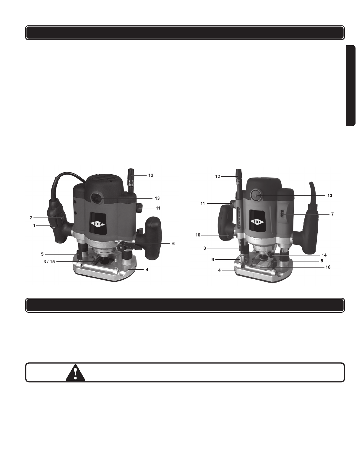
KNOW YOUR PRODUCT
1. On/Off switch
2. Trigger lock-on button
3. Collet
4. Router base
5. Locking bolts for straight guide
6. Plunge locking lever
7. Speed adjustment wheel
8. Depth stop
9. Depth stop turret
10. Depth stop locking knob
11. Depth stop adjustment wheel
12. Fine adjustment knob
13. Carbon brush holder
14. Spindle Lock
15. Collet Nut
16. Dust collection hose adaptor
ENGLISH
FIG A FIG B
OPERATING INSTRUCTIONS
INSTALLING AND REMOVING BITS
There are a number of router bits available for cutting various proles in wood.
This machine is supplied with 3 collets; 1/4", 3/8" & 1/2". Some cutter heads are
too large and do not leave enough space for the dust extraction system. In this
case, a mask should be worn.
WARNING: Disconnect router from the power source before changing router bits
or collets.
To insert the collet:
1. Position the router on its side on the table with the Router Base (4) pointing
towards you.
2. Locate the Spindle Lock (14) at the front of the router.
3. Press it down and hold it in this position.
4. Using the wrench provided, loosen the Collet Nut (15) by turning it counter
clockwise.
5
Page 6
OPERATING INSTRUCTIONS
5. Remove the Collet Nut (15) and clean the spindle.
6. Insert the appropriate Collet (3) into the spindle and screw on the collet nut
hand tight.
CAUTION: Never tighten the collet on this unit without rst installing a router bit.
Tightening an empty collet can damage the collet.
To insert a router bit:
1. Position the router on its side on the table with the Router Base (4) pointing
towards you.
ENGLISH
2. Loosen the Collet Nut (15). Clean and insert the shaft of the router bit into the
collet.
3. Ensure that the router bit shaft is inserted into the collet at least 3/4". If the
shaft “bottoms” out, back it out 1/16" to allow for proper tightening.
4. Press the Spindle Lock (14), hold it in position, and tighten the Collet Nut
(15).
5. Be sure to unplug your router and repeatedly check the tightness of the Collet
Nut (15) when using your router over an extended period.
CAUTION: Handle router bits with care. They are extremely sharp and may
cause cuts and or serious injury.
CAUTION: Before switching the router on, ensure that the collet nut is tight.
LOCKING LEVER FOR ROUTER BODY (Fig. A & B)
The Plunge Locking Lever (6) allows the router bit to be plunged directly into the
workpiece. The body of the router is spring loaded, take care when releasing the
Locking Lever (6). To operate the Plunge Locking Lever (6):
1. Grasp both handles and brace yourself before releasing the Locking Lever
(6).
2. Press downwards to allow the body of the router to move down and into the
workpiece.
3. Lock it in place by depressing the Plunge Locking Lever (6) (Optional).
This unit can be locked in place anywhere along the units vertical travel.
CAUTION: The housing of the router is under spring tension. When you release
the locking lever, it returns to its highest position.
SETTING THE ROUTING DEPTH (FIG. A & B)
WARNING: Disconnect router from the power source before making any
adjustments.
1. Install the desired router bit as described earlier in this manual.
2. Locate the Depth Stop (8) on the router. This adjustable rod is intended to
limit the depth of the cut.
3. Locate the Depth Stop Locking Knob (10) for the Depth Stop (8). Loosen it
by turning it counter-clockwise.
4. Release the Plunge Locking Lever (6) and lower the router down until the end
of the router bit just touches the work piece.
5. Rotate the Depth Stop Adjustment Wheel (11) to set the required cutting
depth using the scale as a guide.
6. Tighten the Depth Stop Locking Knob (10).
7. The router is now set to cut the set depth when plunged into the workpiece.
6
Page 7
OPERATING INSTRUCTIONS
NOTE: It is recommended to make several test cuts in scrap material to conrm
cutting depth is correct.
CUTTING IN SEVERAL PASSES (FIG. A & B)
WARNING: Disconnect router from the power source before making any
adjustments.
It is recommended that particularly deep grooves be cut with several passes to
ensure an accurate cut and quality nish. Use these procedures as a guide only.
Things to consider when making a cut are; depth of cut, width of router bit, type of
bit and type of material being cut. As mentioned earlier in this manual, make test
cuts in similar waste materials. Perform the following procedures to get the best
results.
1. Set the nal desired routing depth as instructed in the previous section.
2. Rotate the Depth Stop Turret (9) to the highest position under the Depth
Stop (8) that allows the router to make a cut.
3. Execute the rst cut.
4. Leave the Depth Stop (8) in position. Rotate the Depth Stop Turret (9) to the
next lowest position and perform the next cut.
5. Again, rotate the Depth Stop Turret (9) to the nal position to execute the last
cut.
CAUTION: To deep a cut will lead to overloading of the motor or difcult operation.
Cutting depth should not exceed 13 mm or 1/2" at one pass. If the desired
cutting depth is greater, make several passes with the depth of cut increased
each time.
ENGLISH
FINE ADJUSTMENT OF CUTTING DEPTH (FIG. A & B)
WARNING: Disconnect router from the power source before making any
adjustments.
If, after setting the desired cutting depth, a small adjustment is needed, it is not
necessary to perform the entire depth setting procedure. This unit is tted with
a Fine Adjustment Knob (12) in order to make minor adjustments to the cutting
depth if needed.
nRotating the Fine Adjustment Knob (12) counter-clockwise will result in a
deeper cut.
nRotating the Fine Adjustment Knob (12) clockwise will result in a shallower
cut.
SWITCHING ON AND OFF (FIG. A & B)
1. Grasp the router securely by the handles. When it is pointing in your direction,
the On/Off Switch (1) is located on the right handle.
2. Keeping the Trigger lock-on button (2), press the On/Off Switch (1). You do
not have to keep the Trigger lock-on button (2) pressed as it remains in
position automatically until you release the On/Off Switch (1) again.
3. To stop the machine, simply release the On/Off Switch (1) and the motor will
stop.
7
Page 8
OPERATING INSTRUCTIONS
USING THE ROUTER
1. Place the tool base on the workpiece while keeping the router bit out of contact
with the material.
2. Switch the tool on and wait until the router bit reaches full speed
3. If appropriate for the cut (e.g. a plunge cut) lower the tool body and bit into the
material.
4. Let the router bit cut into the material smoothly.
5. While cutting along edges make sure that the machine is always guided
against the direction of rotation of the cutter. While cutting along edges with
ENGLISH
the direction of rotation the machine can shoot away unexpectedly.
6. Slide the tool forward on the surface of the workpiece while keeping the tool
base at and moving steadily until the completion of the cut.
7. After use, bring the machine up into its resting position before switching off.
Switch off the machine and wait for the cutter to come to a complete stop
before putting the machine down
NOTE:
nIf the tool is moved too quickly, the quality of the cut will be low and damage to
the bit and/or the motor may result.
nIf it is moved too slowly, there could be a poor cutting effect due to heat. Opti-
mum speed depends on the size of the tool bit, type of workpiece and the cut
depth. It is advisable to make an experimental cut on similar waste material
before performing the actual cut.
CAUTION: Abnormal vibrations may be due to a blunt cutter head.
ADJUSTABLE SPEED
The speed setting is located at the front of the housing. Turn the dial to increase
or decrease the speed. The smaller the router bit cutter head the higher the
speed. The larger the router bit cutter head, the lower the speed. A router bit
cutter head, which runs too fast, causes scorching of the workpiece and leaves
burn marks.
WARNING: Do not change the speed when the machine is working under load.
CUTTING DIRECTION
To prevent the cutter head from jumping and to obtain a good result, carry out ex-
terior cuts in a counter clockwise direction and interior cuts in a clockwise direction.
ASSEMBLY OF EDGE GUIDE
1. Locate the Straight Edge Guide and guide rods.
2. Fasten the Straight Edge Guide to the guide rods with the adjusting screw.
3. Slide the guide rods into the corresponding castings on the router base.
4. Clamp the Scale onto one of the guide rods.
5. When the desired distance is attained, secure the Straight Edge Guide in
place with the adjusting screws.
USING THE EDGE GUIDE
The edge guide can be used for cutting parallel to the edge of the workpiece.
1. Release the four screws securing the edge guide and push them in so that the
guide is at the desired distance from the cutter head.
8
Page 9

OPERATING INSTRUCTIONS
2. Tighten the four securing screws.
3. Press the guide assembly securely against the edge of the workpiece and
execute the cut as described earlier.
TEMPLATE GUIDE
The template guide attaches to the base of the machine and ensures that the
machine can follow a specic cutting pattern. Only certain sizes of router bits can
be used. The size is limited by the size of the hole in the template guide. The dust
extraction system can be used with this accessory.
To install the template guide:
1. Lay the router on its side.
2. Loosen and remove the four Phillips screws attaching the plastic base to the
casting.
3. Note the recess in the plastic base.
4. Hold the template guide with the sleeve to the outside and place it in the recess.
5. Align the holes in the plastic base with the threaded holes in the casting and
tighten the four Phillips screws.
6. Re-install the dust extraction components and secure them with nuts and bolts.
TRIMMER GUIDE
ENGLISH
The Trimmer Guide works in the same manner as the Straight Edge Guide however
it is used for routing edges which are not straight. Attach the Trimmer Guide to the
straight edge guide using the screws provided. Common uses include laminate
countertops and veneer nishes.
DUST EXTRACTION OUTLET
You are advised to use the dust extraction outlet provided with this unit. Connect
a suitable commercial vacuum cleaner or dust collection unit to the dust extraction
outlet to maximize dust collection. In order to operate efciently, the outlet must
project from the rear of the router. Two nuts and bolts are supplied to attach it.
To attach:
1. Hold the extractor outlet in position and lay the router on its side.
2. Push the long bolt through the router base until it projects at the wider point for
the extractor outlet.
3. Place the nut in the hexagonal shaped recess.
4. Tighten the bolt with a suitable wrench and moderate force until the outlet is
securely attached.
5. Repeat the procedure at the other side.
CAUTION: Dust may cause respiratory problems. Certain laminated board materials
are carcinogenic. After work, always remove all dust from machine.
NOTE: Turn off the switch and make sure the tool is unplugged before performing
any maintenance on the tool.
9
Page 10

MAINTENANCE
NOTE: Turn off the switch and make sure the tool is unplugged before
performing any maintenance to the tool.
WARNING:
Turn off your router at once, unplug and inspect it for serious problems if:
Moving parts get stuck
Speed drops to an abnormally low level
The motor housing gets hot
Sparks or odours emit from the casing
ENGLISH
nCheck the brushes occasionally and replace if worn. When the area of abra-
sion reaches the limit line, replacement is necessary.
1. Unplug the tool.
2. Unscrew the round brush covers on each side of the body and pull the
brushes out to check or replace them.
3. Keep the carbon brush clean and able to slide freely inside the clip.
4. Both brushes should be replaced simultaneously.
5. If you replace the brushes, run the tool without load for 15 minutes to
seat the brushes properly.
nKeep the vents clear of dust and debris. This will help prevent possible
electrical shorts and ensure proper cooling.
nKeep the tool housing and handle clean and free of oil and grease using mild
soap and a damp (not wet) cloth. Cleaning with solvents like brake uid, gasoline, petroleum-based products, etc. can harm the plastic and break down the
integrity of the double insulating system.
nAvoid overloading your router. It will become hot and lose efciency.
nInspect the cord regularly and have it replaced by an authorized repair facility if
it is damaged.
nLubrication for this tool is done at the factory and should not be necessary
again under normal use.
nCheck the router bit regularly for cracking and other damage. Do not use a
damaged bit.
nAn authorized repair centre should do any repairs, modication, or mainte-
nance that involve disassembling the router.
nAny damage to the tool should be corrected at an authorized repair centre.
PARTS LIST
Please refer to Schematic Drawing on page 24.
No. Description No. Description
1 Tapping screw 45 Sliding lock knob
2 Back cover 46 Phillips screw
3 Tapping screw 47 Locking bar
4 Thermo protector 48 Locking spring
5 Motor housing 49 Phillips screw
6 Circuit board 50 Front board
7 Housing board 51 Locking spring
8 Tapping screw 52 Collet
9 Tapping screw 53 Collet nut
10 Flat washer 54 Guide bar
11 Brush holder 55 Spring
12 Carbon brush 56 Bushing
13 Brush holder cover 57 Guide bar sleeve
14 Label 58 C-clip
10
Page 11

PARTS LIST
Please refer to Schematic Drawing on page 24.
No. Description No. Description
15 Scale 59 Guide bar
16 Knob 60 Spring
17 Stator 61 Guide bar sleeve
18 Bearing 62 Screw
19 Rotor 63 Depth stop turret
20 Fan bafe 64 Steel ball
21 Screw 65 Spring
22 Bearing plate 66 Adjusting screw
23 Bearing 67 Spring
24 Spring 68 Router base
25 Plastic screw 69 Plastic plate
26 Right handle 70 Phillips screw
27 Flat washer 71 Wrench
28 Spring washer 72 Straight guide
29 Screw 73 Guide rod
30 Right handle cover 74 Dust exhaust adaptor
31 Plug 75 Scale
32 Cord 76 Plastic plate
33 Cord cover 77 Screw
34 Left handle 78 Buttery screw
35 Capacitor 79 Sleeve
36 Plate 80 Location board
37 Screw 81 Guide wheel assembly
38 Switch 82 Square nut
39 Left handle cover 83 Template guide
40 Screw 84 Phillips screw
41 Front cover 85 Nut
42 Threaded bearing cap 86 Short sliding socket
43 Torsion spring 87 Long sliding socket
44 Locking screw 88 Pan head screw
ENGLISH
WARRANTY
ITC branded power tools, air nailers staplers and compressors are designed for use in DIY (do-it-yourself), light or
intermittent duty, semi-professional applications. They are not intended for use in professional, production, industrial or
continual use applications.
ITC makes every effort to ensure that its products meet high quality and durability standards and are warranted for two
years against manufacturers’ faults and defects for a period of two years from the date of purchase to the original owner.
ITC will REPAIR OR REPLACE (at our discretion) merchandise deemed by the company to be defective, provided that it
is has not been misused, abused, altered, or repaired by anyone other than an authorized repair centre.
Please consult the ITC catalogue or your nearest ITC distributor to determine those products that are covered by our overthe counter warranty. Any ITC tool that fails during normal use and within the specied warranty period and qualies for
over-the counter warranty must be returned to its point of purchase for replacement or credit. Any item not listed as overthe-counter warranty must be shipped, prepaid freight, to an authorized repair depot accompanied by a copy of the invoice
specifying the date that the item was purchased. Returned tools that are not accompanied by a proof of purchase (Copy of
Invoice) will not be repaired or replaced under warranty.
This warranty does not extend to normal wear or consumable parts such as brad and staple gun driver blades, grinding
discs, saw blades, driver bits, electric motor brushes, worn chords, etc. It also does not apply to ITC tools used in
professional, production, industrial or continual use applications.
For a listing of the authorized repair centers please refer to the ITC catalogue.
WARRANTY
11
Page 12

IMPORTANTE DIRECTIVES DE SÉCURITÉ
AVERTISSEMENT : Durant l’usage des outils électriques, des machines et de
l’équipement, des précautions de sécurité de base devraient toujours être
observées pour réduire le risque d’incendie, de choc électrique et de blessures
corporelles.
LIRE TOUTES LES INSTRUCTIONS AVANT D’UTILISER CET OUTIL.
1. CONSERVEZ L’AIRE DE TRAVAIL PROPRE. Le désordre invite les bles-
sures.
2. SOYEZ CONSCIENT DE VOTRE ENVIRONNEMENT DE TRAVAIL. Ne pas
utiliser les outils motorisés dans des endroits humides, mouillés ou insufsamment éclairés. Ne pas exposer vos outils à la pluie. Conservez l’aire de travail
bien éclairée. Ne pas utiliser les outils en présence de gaz ou de liquides
inammables.vvv
3. CONSERVEZ LES ENFANTS ET LES SPECTATEURS À L’ÉCART. Tous les
enfants doivent être tenus à l’écart de l’aire de travail. Ne leur permettez pas
de toucher les machines, les outils ou les cordes de rallonge. Les visiteurs
peuvent causer une distraction et on doit les protéger contre les blessures cor-
porelles.
4. LES OUTILS MIS À LA TERRE doivent être branchés dans une prise qui elle-
même a été installée et mise à la terre adéquatement. Si l’outil avait un problème électrique, la mise à la terre offre un cheminement de faible résistance
transportant l’électricité à la mise à la terre loin de l’opérateur. Ne jamais
enlever la broche de mise à la terre ou modier la che. En cas de doute quant
à l’installation appropriée de la mise à la terre, consultez avec un électricien
qualié.
5. PRENEZ LES PRÉCAUTIONS APPROPRIÉES CONCERNANT L’ISOLATION
DOUBLE. Cet outil est doublement isolé. Il est équipé d’une che polarisée.
Une lamelle de la che est plus large que l’autre et elle ne s’adaptera à une
FRANÇAIS
prise de courant polarisée que d’une seule façon. Si vous éprouvez des difcultés pour insérer la che, inversez-la. Si elle ne s’adapte toujours pas, ne
pas tenter de modier la che. Demandez à un électricien qualié d’installer
une prise de courant polarisée.
6. PRÉVENEZ LES CHOCS ÉLECTRIQUES. Éviter le contact de votre corps
avec les surfaces mises à terre : tuyaux, radiateurs, cuisinières et réfrigérateurs. Si votre corps est mis à la terre, le risque de choc électrique est augmenté. Si vous effectuez des travaux dans les secteurs où des ls électriques
sous tension pourraient être touchés, tentez de déterminer s’il y a un risque
de choc électrique. Mais en toute circonstance, NE PAS TOUCHER AUNE
PARTIE MÉTALLIQUE DE L’OUTIL durant son usage. Toujours tenir l’outil par
la poignée en plastique pour prévenir les chocs électriques en cas de contact
avec un l sous tension.
7. NE PAS ABUSER LE CORDON.
le cordon ou tirer sur le cordon pour le débrancher. Protégez le cordon des
sources potentielles de dommage : La chaleur, l’huile et les solvants, les rebords aiguisés ou les pièces mobiles. Remplacez les cordons endommagés
immédiatement.
8. POUR LE TRAVAIL À L’EXTÉRIEUR, TOUJOURS UTILISER UNE CORDE
DE RALLONGE HOMOLOGUÉE POUR L’USAGE À L’EXTÉRIEUR. Une
corde de rallonge homologuée pour usage à l’extérieur doit porter la marque
« W-A » ou « W ».
9. NE PAS EXPOSER LES OUTILS ÉLECTRIQUES À L’HUMIDITÉ. La pluie ou
les conditions humides peuvent causer l’inltration d’eau dans l’outil et il peut
Ne jamais transporter votre ponceuse par
12
Page 13

IMPORTANTE DIRECTIVES DE SÉCURITÉ
10. ASSUREZ-VOUS QUE LA CORDE DE RALLONGE QUE VOUS
UTILISEZ EST DE CALIBRE SUFFISANT POUR SA LONGUEUR.
Recommended Minimum Wire Gauge for Extension Cords
Amps from
Tool Nameplate
0 - 5 amps 16 ga. 16 ga. 16 ga. 14 ga. 12 ga. 12 ga.
5.1 - 8 amps 16 ga. 16 ga. 14 ga. 12 ga. 10 ga. Do Not Use
8.1 - 12 amps 14 ga. 14 ga. 12 ga. 10 ga. Do Not Use Do Not Use
12.1 - 15 amps 12 ga. 12 ga. 10 ga. 10 ga. Do Not Use Do Not Use
15.1 - 20 amps 10 ga. 10 ga. 10 ga. Do Not Use Do Not Use Do Not Use
11. REMISEZ L’ÉQUIPEMENT QUI N’EST PAS UTILISÉ. Remisez l’équipement
dans un endroit sec pour empêcher la rouille. L’équipement devrait aussi être
remisé dans un endroit haut ou sous clé, hors d’atteinte de la portée des
enfants.
12. NE PAS FORCER L’OUTIL. Il fera un meilleur travail, de manière plus sécuritaire, au rythme pour lequel il est conçu.
13. UTILISEZ L’OUTIL APPROPRIÉ. Ne pas forcer un petit outil ou un accessoire
à faire le travail d’un outil industriel plus gros. Ne pas utiliser un outil à une n
pour laquelle il n’a pas été conçu.
14. HABILLEZ-VOUS DE MANIÈRE APPROPRIÉE. Ne pas porter de vêtement
ample ou de bijoux. Ils peuvent être attrapés par les pièces mobiles. Des
gants de protection à l’épreuve de la conductivité électrique et des souliers
antidérapants sont recommandés durant le travail. Portez un couvre-tête de
protection pour recouvrir les cheveux longs et prévenir les emmêlements.
15. PROTÉGEZ VOS YEUX. Utilisez un masque qui recouvre le visage tout entier
si le travail que vous effectuez produit de la limaille métallique, de la poussière
ou des éclats de bois. Des lunettes de sécurité sont appropriées dans les
autres situations. Portez un masque à poussière propre si le travail implique la
création d’une quantité appréciable de poussière ne ou à gros grains.
16. FIXEZ SOLIDEMENT LA PIÈCE DE TRAVAIL. Utilisez des pinces ou un étau
pour tenir la pièce de travail. C’est beaucoup plus sécuritaire que l’usage de
vos mains et ceci libère vos deux mains pour contrôler l’outil.
17. NE PAS VOUS ÉTIREZ. Conservez vos pieds sur le sol et maintenez votre
équilibre en tout temps. Ne vous avancez pas au-dessus ou à travers les machines qui sont en mode de fonctionnement.
18. MAINTENEZ L’OUTIL EN BON ÉTAT. Conservez l’outil eflé et propre pour
une meilleure performance et plus de sécurité. Observez les instructions pour
la lubrication et la performance sécuritaire. Respectez les directives de lubrication et de changement des accessoires. Conservez les poignées propres,
sèches et libres d’huile et de graisse.
19. ÉVITEZ LA MISE EN MARCHE ACCIDENTELLE. Assurez-vous que
l’interrupteur est à la position « ARRÊT » avant de brancher l’outil.
20. TOUJOURS VÉRIFIEZ ET RETIREZ LES CLÉS DE RÉGLAGE ET LES CLÉS
ANGLAISES avant de mettre l’outil en marche. Laissez en place, ces pièces
peuvent se détacher de la pièce qui tourne et causer des blessures.
21. NE PAS UTILISER L’OUTIL SI L’INTERRUPTEUR « EN MARCHE / ARRÊT »
NE FONCTIONNE PAS CORRECTEMENT. Faire réparer votre outil avant de
l’utiliser.
22. DÉBRANCHEZ L’OUTIL DE LA PRISE DE COURANT AVANT DE FAIRE LES
RÉGLAGES. Les changements de pièce ou d’accessoire peuvent être dan-
gereux si l’outil peut être activé accidentellement.
23. SOYEZ ALERTE. Surveillez vos mouvements et utilisez le sens commun.
N’utilisez pas un outil quand vous êtes fatigué.
25' long 50' long 75' long 100' long 150' long 200' long
FRANÇAIS
13
Page 14

IMPORTANTE DIRECTIVES DE SÉCURITÉ
24. EXAMINEZ POUR DES PIÈCES ENDOMMAGÉES.
toute pièce qui est endommagée devrait être soigneusement examinée pour
s’assurer qu’elle fonctionnera adéquatement et qu’elle remplira sa fonction.
Vériez pour l’alignement et le coincement des pièces mobiles, le bris des
pièces, les montures et toutes autres conditions qui pourraient affecter dans
lesonfonctionnement. Examinez les vis et resserrez celles qui sont relâchées.
Toute pièce qui est endommagée devrait être correctement réparée ou remplacée par le centre de service autorisé, sauf si autrement indiqué ailleurs manuel
de l’utilisateur. Les interrupteurs défectueux doivent être remplacés par un
centre de service autorisé. Ne pas utiliser l’outil si l’interrupteur ne fonctionne
pas correctement.
25. PIÈCES DE RECHANGE. Pour le service, n’utilisez que des pièces de
rechange identiques seulement.
26. SERVICE ET RÉPARATION doivent être effectués par des techniciens qualiés
à un centre de service autorisé. Des outils qui ne sont pas réparés adéquatement peuvent causés un choc ou des blessures graves.
Avant d’utiliser cet outil,
CONSEILS DE SÉCURITÉ SPÉCIAUX POUR LA DÉFONCEUSE
n TENEZ LA FRAISE AVEC GRAND SOIN.
n EXAMINEZ LA FRAISE ATTENTIVEMENT AVANT L’UTILISATION POUR
DÉTECTER DES FENTES OU DES DOMMAGES. Remplacez la fraise si vous
trouvez un défaut.
n ÉVITEZ DE HEURTER DES CLOUS AVEC LA FRAISE. Vériez qu’il n’y a pas
de clous dans la pièce de bois.
n TENEZ L’ÉQUIPEMENT SOLIDEMENT AVEC LES DEUX MAINS.
n GARDEZ TOUJOURS LES MAINS HORS DE PORTÉE DES PIÈCES
FRANÇAIS
ROTATIVES.
n ASSUREZ-VOUS QUE LA FRAISE N’EST PAS EN CONTACT AVEC LA
PIÈCE AVANT DE METTRE LA TOUPIE EN MARCHE.
n LAISSEZ LA DÉFONCEUSE TOURNER À VIDE PENDANT UN CERTAIN
TEMPS AVANT DE LA METTRE EN CONTACT AVEC LA PIÈCE ET VÉRIFIEZ QUE LA TOUPIE NE VIBRE PAS À CAUSE D’UNE MAUVAISE
INSTALLATION DE LA FRAISE.
n GARDEZ TOUJOURS À L’ESPRIT LA DIRECTION DE ROTATION DE LA
FRAISE ET LA DIRECTION DANS LAQUELLE VOUS DEVEZ METTRE LA
TOUPIE EN CONTACT AVEC LA PIÈCE.
n NE LAISSEZ PAS LA MACHINE TOURNER SANS SUPERVISION.
n NE TOUCHEZ PAS LA FRAISE IMMÉDIATEMENT APRÈS L’AVOIR UTILISÉ.
La fraise est extrêmement chaud et peut vous brûler.
n SOULEVEZ LA MACHINE DE LA PIÈCE APRÈS L’AVOIR MIS HORS TEN-
SION ET QUE LA FRAISE SE SOIT
Votre nouvelle Défonceuse inclut :
nToupie plongeante de 1/2 po
nGuide de rebord
nGuide d’afeurage
nGuide de gabarit
nTrois pinces de serrage – 1/4 po, 3/8 po et 1/2 po
nDouze mèches à tige de 1/2 po avec embout en carbure :
Mèche de 1/2 po pour rognage afeuré
Mèche à cavet de 7/8 po
Mèche à arrondir de 7/8 po
Mèche à arrondir de 1-1/8 po
14
Page 15

Mèche à doucine de 1 po
Mèche à chanfreiner à 45 degrés, de 1-1/4 po
Mèche pour coupes droites de 1/4 po
Mèche pour coupes droites de 1/2 po
Mèche pour coupes droites de 5/8 po
Mèche à queue d’aronde de 1/2 po
Mèche à rainure en V de 90 degrés, de 1/2 po
Mèche pour trous de 1/2 po
nAdaptateur de boyau pour collecteur de poussière/aspirateur
nClé pour pince de serrage
nClé pour le réglage de la tourelle
nJeu de balais de carbone de rechange
nCoffret moulé par soufage
nGuide d’utilisation
CARACTÉRISTIQUES :
n120 volts, 60 Hz, 15 A
nVitesse variable 9 000 – 23 000 tr/min
nInterrupteur verrouillable
nButée à sept positions, à profondeur de 51 mm (2 po)
nVerrou d’arbre
nBoitier à ni doux
nBalais de moteur facile à accéder
nÀ double isolation
nCertication de la CSA
nPoids de l’outil : 3,1 kg (7 lb)
FRANÇAIS
FAMILIARISEZ-VOUS AVEC LE PRODUIT
1. Interrupteur marche/arrêt
2. Bouton de verrouillage du déclencheur
3. Pince de serrage
4. Base de la toupie
5. Boulons de verrouillage pour guide de rebord droit
6. Levier de verrouillage de profondeur de coupe
7. Roue de réglage de vitesse
8. Butée de profondeur
9. Tourelle de butée de profondeur
10. Bouton de verrouillage de butée de profondeur
11. Roue de réglage de butée de profondeur
12. Bouton de réglage précis
13. Porte-balais de carbone
14. Verrou de broche
15. Écrou de pince
16. Adaptateur de boyau pour collection de poussière
15
Page 16

FAMILIARISEZ-VOUS AVEC LE PRODUIT
!
FIG A
FIG B
PROCÉDURES D’UTILISATION
INSERTION ET RETRAIT DES MÈCHES (FIGS. A ET B)
Plusieurs mèches existent pour couper divers prols dans le bois. Cet outil est
vendu avec 3 pinces de serrage: 1/4 po, 3/8 po et 1/2 po. Certaines têtes de coupe
FRANÇAIS
sont trop grandes et ne laissent pas assez d’espace pour le système de collection
de poussière. Dans ce cas, l’utilisateur devrait porter un masque antipoussières.
AVERTISSEMENT : Débranchez la toupie de la source d’alimentation avant de
changer les mèches ou les pinces de serrage.
Insertion d’une pince de serrage :
1. Positionnez la toupie sur son côté sur la table, avec la base de la toupie (4)
dirigée vers vous.
2. Cherchez le verrou de la broche (14) à la partie avant de la toupie.
3. Enfoncez-le et maintenez-le dans cette position.
4. Utilisez la clé fournie pour desserrer l’écrou de pince (15) en le tournant dans
le sens antihoraire.
5. Retirez l’écrou de pince (15) et nettoyez la broche.
6. Insérez la pince de serrage appropriée dans la broche et serrez à la main
l’écrou de pince.
MISE EN GARDE : Ne serrez jamais la pince de serrage de cet outil sans insérer
d’abord une mèche. Si vous serrez une pince de serrage vide, vous risquez
d’endommager la pince.
Insertion d’une mèche :
1. Positionnez la toupie sur son côté sur la table, avec la base de la toupie (4)
dirigée vers vous.
2. Desserrez l’écrou de pince (15). Nettoyez les pièces et insérez l’arbre de la
mèche dans la pince de serrage.
3. Assurez-vous que l’arbre de la mèche est inséré à une profondeur d’au moins
19 mm (3/4 po) dans la pince de serrage. Si l’arbre touche au fond, retirez-le
de 1/16 po pour assurer un serrage correct.
16
Page 17

PROCÉDURES D’UTILISATION
4. Enfoncez le verrou de la broche (14), maintenez-le dans cette position, et
serrez l’écrou de pince (15).
5. Débranchez la toupie et vériez périodiquement le serrage de l’écrou de pince
(15) lorsque vous utilisez la toupie pour une période prolongée.
MISE EN GARDE : Manipulez les mèches avec soin. Elles sont extrêmement
tranchantes et peuvent vous couper et(ou) causer des blessures graves.
MISE EN GARDE : Avant de mettre la toupie sous tension, assurez-vous que
l’écrou de pince est bien serré.
LEVIER DE VERROUILLAGE POUR LE CORPS DE LA TOUPIE
(FIGS. A ET B)
Le levier de verrouillage de profondeur de coupe (6) vous permet d’enfoncer la
mèche directement dans le morceau de bois. Le corps de la toupie est doté d’un
ressort ; faites attention en relâchant le levier de verrouillage (6).
Utilisation du levier de verrouillage de profondeur de coupe (6) :
1. Saisissez les deux poignées et positionnez-vous solidement avant de relâcher
le levier de verrouillage (6).
2. Poussez vers le bas pour permettre au corps de la toupie de descendre dans
le morceau de bois.
3. Verrouillez la profondeur en abaissant le levier de verrouillage de
profondeur de coupe (6) (facultatif).
Cet outil peut être verrouillé à n’importe quelle hauteur sur sa course verticale.
MISE EN GARDE : Le boîtier de la toupie est tendu par un ressort. Lorsque vous
relâchez le levier de verrouillage, il retourne à la position la plus élevée.
RÉGLAGE DE LA PROFONDEUR DE COUPE (FIGS. A ET B)
AVERTISSEMENT : Débranchez la toupie de la source d’alimentation avant
d’effectuer tout réglage.
1. Insérez la mèche désirée, tel que décrit dans une partie précédente de ce
guide.
2. Cherchez la butée de profondeur (8) de la toupie. La fonction de cette tige
réglable est de limiter la profondeur de la coupe.
3. Cherchez le bouton de verrouillage de butée de profondeur (10) pour la
butée de profondeur (8). Desserrez-le en tournant dans le sens antihoraire.
4. Relâchez le levier de verrouillage de profondeur de coupe (6) et abaissez
la toupie jusqu’à ce que l’embout de la mèche touche à peine le morceau de
bois.
5. Tournez la roue de réglage de butée de profondeur (11) pour régler la
profondeur de coupe requise en utilisant l’échelle en tant que guide.
6. Serrez le bouton de verrouillage de butée de profondeur (10).
7. La toupie est maintenant réglée pour couper à la profondeur réglée lorsque
l’outil est abaissé sur le morceau de bois.
FRANÇAIS
REMARQUE : Nous vous recommandons d’effectuer plusieurs coupes d’essai sur
une pièce de rebut pour vous assurer que la profondeur de coupe est
correcte.
17
Page 18

PROCÉDURES D’UTILISATION
COUPER EN PLUSIEURS PASSES (FIGS. A ET B)
AVERTISSEMENT : Débranchez la toupie de la source d’alimentation avant
d’effectuer tout réglage.
Si vous devez couper des rainures particulièrement profondes, nous vous
recommandons de le faire en plusieurs passes an d’assurer une coupe précise et
un ni de qualité. Utilisez ces procédures en tant que guide seulement.
Considérez les éléments suivants en effectuant une coupe : profondeur de la
coupe, largeur de la mèche, type de mèche et type de matériel à couper. Comme
mentionné plus haut dans ce guide, effectuez quelques coupes d’essai sur une
pièce de rebut d’un matériel similaire. Suivez les procédures ci-dessous pour
obtenir les meilleurs résultats.
1. Réglez la profondeur de coupe désirée, tel qu’indiqué dans la section
précédente.
2. Tournez la tourelle de butée de profondeur (9) à la position la plus élevée sous
la butée de profondeur (8) qui permet à la toupie d’effectuer une coupe.
3. Exécutez la première coupe.
4. Laissez la butée de coupe (8) dans cette position. Tournez la tourelle de
butée de profondeur (9) à la position inférieure suivante et effectuez la
prochaine coupe.
5. Tournez encore une fois la tourelle de butée de profondeur (9) à la position
nale pour exécuter la dernière coupe.
MISE EN GARDE : Les coupes à une profondeur excessive entraîneront la sur-
charge du moteur et un fonctionnement médiocre. La profondeur de coupe ne
FRANÇAIS
devrait pas excéder 13 mm (1/2 po) dans une seule passe. Si la profondeur
de coupe désirée est plus élevée, effectuez plusieurs passes en augmentant
la profondeur de la coupe à chaque passe.
RÉGLAGE PRÉCIS DE LA PROFONDEUR DE COUPE
(FIGS. A ET B)
AVERTISSEMENT : Débranchez la toupie de la source d’alimentation avant
d’effectuer tout réglage.
Si un réglage léger est nécessaire après avoir réglé la profondeur de coupe
désirée, il n’est pas nécessaire de répéter la procédure complète de réglage de
la profondeur. Cet outil est doté d’un bouton de réglage précis (12) qui permet
d’effectuer des réglages mineurs de la profondeur de coupe.
nTournez le bouton de réglage précis (12) dans le sens antihoraire pour obte-
nir une coupe plus profonde.
nTournez le bouton de réglage précis (12) dans le sens horaire pour obtenir
une coupe moins profonde.
MISE SOUS TENSION OU HORS TENSION (FIGS. A ET B)
1. Saisissez la toupie solidement par les deux poignées. Lorsque l’interrupteur
marche/arrêt (1) est dirigé vers vous, il sera situé sur la poignée droite.
2. Tout en enfonçant le bouton de verrouillage du déclencheur (2), appuyez
sur l’interrupteur marche/arrêt (1). Vous ne devez pas garder le bouton de
verrouillage du déclencheur (2) enfoncé parce qu’il demeurera
automatiquement dans cette position jusqu’à ce que vous relâchiez
l’interrupteur marche/arrêt (1).
3. Pour arrêter l’outil, il suft de relâcher l’interrupteur marche/arrêt (1) et le
moteur s’arrêtera.
18
Page 19

PROCÉDURES D’UTILISATION
UTILISATION DE LA TOUPIE
1. Placez la base de l’outil sur la pièce en vous assurant que la mèche n’entre
pas en contact avec le matériel.
2. Mettez l’outil en marche et attendez que la mèche atteigne sa pleine vitesse.
3. Si c’est nécessaire pour la coupe (par exemple, pour couper une rainure),
baissez le corps de l’outil et la mèche dans le matériel.
4. Laissez la mèche couper le matériel sans à-coups.
5. En coupant le long des rebords, assurez-vous que l’outil est toujours guidé
contre le sens de rotation de la mèche. Si vous coupez le long des rebords
dans le sens de rotation, l’outil peut s’éloigner subitement. 6. Glissez l’outil
vers l’avant sur la surface de la pièce en gardant la base à plat et en déplaçant l’outil à une vitesse constante jusqu’à ce que la coupe soit terminée.
7. Après l’usage, soulevez l’outil pour le mettre à sa position de repos avant de
mettre l’outil hors tension. Arrêtez l’outil et attendez que la mèche soit complètement immobile avant de placer l’outil sur toute surface.
REMARQUE :
nSi l’outil est déplacé trop rapidement, la coupe sera de qualité médiocre et la
mèche et(ou) le moteur peut être endommagé.
nS’il est déplacé trop lentement, la coupe peut être médiocre en raison de la
surchauffe de la mèche. La vitesse de coupe optimale dépend de la taille de
la mèche, du genre de pièce à couper et de la profondeur de la coupe. Nous
vous recommandons de faire des coupes d’essai sur une pièce de rebut d’un
matériel similaire avant de faire la coupe sur la pièce même.
FRANÇAIS
MISE EN GARDE : Des vibrations anormales peuvent être causées par une tête
de coupe émoussée.
VITESSE RÉGLABLE
Le réglage de la vitesse se trouve sur la partie avant du boîtier. Tournez le cadran
pour augmenter ou diminuer la vitesse. La vitesse devrait être plus élevée si la
tête de coupe de la mèche est petite. La vitesse devrait être moins élevée si la
tête de coupe de la mèche est grande. Une tête de coupe de mèche qui tourne
trop rapidement peut brûler la pièce et laisser des marques de brûlage.
AVERTISSEMENT : Ne changez pas la vitesse lorsque l’outil fonctionne avec une
charge.
DIRECTION DE COUPE
Pour empêcher la tête de coupe de sauter et pour obtenir des résultats
satisfaisants, effectuez les coupes extérieures dans un sens antihoraire et les
coupes intérieures dans un sens horaire.
ASSEMBLAGE DU GUIDE DE REBORD
1. Cherchez le guide de rebord droit et les tiges de guidage.
2. Fixez le guide de rebord aux tiges de guidage avec la vis de réglage.
3. Glissez les tiges de guidage dans les parties moulées correspondantes de la
base de toupie.
4. Attachez l’échelle sur une des tiges de guidage.
5. Une fois que la distance désirée est obtenue, xez le guide de rebord droit
dans sa position avec les vis de réglage.
19
Page 20

PROCÉDURES D’UTILISATION
UTILISATION DU GUIDE DE REBORD
Le guide de rebord peut être utilisé pour couper en parallèle le long du rebord de
la pièce.
1. Desserrez les quatre vis xant le guide de rebord et poussez-les vers
l’intérieur de façon à ce que le guide soit à la distance appropriée de la tête de
coupe.
2. Serrez les quatre vis de xation.
3. Poussez l’ensemble de guide solidement contre le rebord de la pièce et exécutez la coupe tel que décrit plus haut.
GUIDE DE GABARIT
Le guide de gabarit s’attache à la base de l’outil et il assure que l’outil peut
suivre un motif de coupe spécique. Seulement des mèches d’une certaine
taille peuvent être utilisées. La taille est limitée par la dimension du trou dans le
guide du gabarit. Le système d’extraction de poussière peut être utilisé avec cet
accessoire.
Pose du guide de gabarit :
1. Placez la toupie sur son côté.
2. Desserrez et retirez les quatre vis Phillips xant la base en plastique à la pièce
moulée.
3. Repérez la rainure dans la base en plastique.
4. Maintenez le guide de gabarit avec le manchon positionné à l’extérieur et
placez-le dans la rainure.
FRANÇAIS
5. Alignez les trous de la base en plastique avec les trous letés de la pièce
moulée et serrez les quatre vis Phillips.
6. Posez les composants d’extraction de poussière et xez-les avec les écrous et
les boulons.
GUIDE D’AFFLEURAGE
Le guide d’afeurage fonctionne de la même façon que le guide de rebord droit.
Toutefois, il est utilisé pour former les rebords qui ne sont pas droits. Attachez le
guide d’afeurage au guide de rebord droit avec les vis fournies. Ce guide est
normalement utilisé sur les dessus de comptoir fabriqués de matériaux stratiés et
les nis à bois de placage.
BUSE D’ASPIRATION DE POUSSIÈRE
Nous vous recommandons d’utiliser la buse d’aspiration de poussière fournie avec
cet appareil. Connectez un aspirateur commercial approprié ou un collecteur
de poussière à la buse d’aspiration de poussière pour maximiser la collection de
poussière. Pour fonctionner efcacement, la buse doit sortir de la partie arrière de
la toupie. Deux écrous et boulons sont fournis pour la xation.
Fixation :
1. Maintenez la buse d’aspiration à la position appropriée et placez la toupie sur
le côté.
2. Poussez le long boulon à travers la base de la toupie jusqu’à ce qu’il dépasse
de la partie plus épaisse de la buse d’aspiration.
3. Insérez l’écrou dans la partie en retrait hexagonale.
4. Serrez le boulon avec une clé appropriée en appliquant une force moyenne
jusqu’à ce que la buse soit bien xée.
5. Répétez cette procédure sur l’autre côté.
20
Page 21

PROCÉDURES D’UTILISATION
MISE EN GARDE : La poussière peut causer des troubles respiratoires. Certains
matériaux des planches stratiées sont carcinogènes. Enlevez toujours toute
la poussière de l’outil après avoir terminé le travail.
REMARQUE : Arrêtez l’outil avec l’interrupteur et débranchez-le avant d’effectuer
tout entretien sur l’outil.
ENTRETIEN
REMARQUE : La défonceusedoit être hors fonction et débranchée avant de faire
des travaux d’entretien.
AVERTISSEMENT :
Éteignez l’outil immédiatement, débranchez-la et inspectez-la à l’affût de
problèmes graves si :
les pièces en mouvement se coincent
la vitesse tombe à un niveau anormalement bas
le boîtier du moteur devient chaud
des étincelles ou odeurs s’échappent du boîtier
Vériez les contacts à balai occasionnellement et remplacez-les s’ils sont
usés. Lorsqu’un balai est usé jusqu’à la marque de limite d’usure, il faut le
remplacer.
1. Débranchez l’outil.
2. Dévissez les couvercles ronds des contacts à balais de chaque côté
du boîtier et retirez les contacts pour les vérier ou les remplacer.
3. Conservez les contacts à balais nettes et libre à glisser dans leur
manchons.
4. Remplacez les deux contacts à la même temps.
5. Si vous remplacez les contacts, faites fonctionner l’outil sans charge
pendant 15 minutes pour faciliter l’insertion appropriée des contacts à
balai.
Conservez les orices de ventilation libres de poussière et de débris. Ceci
aidera à prévenir les courts-circuits possibles et assurera la ventilation adéquate.
Conservez le boîtier et la poignée de l’outil propres et libres de graisse et
d’huile en les nettoyant avec un linge savonneux et humide (mais non
mouillé). Le nettoyage avec les solvants tels que le liquide à freins, l’essence,
les produits à base de pétrole, etc. peuvent abîmer le plastique et réduire
l’intégrité du système de double isolation.
Éviter de surcharger votre défonceuse. Elle chauffera et perdra son efcacité.
Examinez le cordon régulièrement et faites-le remplacer par un centre de
service autorisé s’il est endommagé.
La lubrication de cet outil est complétée à l’usine et ne devrait pas être
requise de nouveau sous les conditions d’usage normal.
Vériez la fraise régulièrement pour les ssures et autres dommages. Ne pas
utiliser une fraise endommagé.
Tous les travaux de réparation, de modication ou d’entretien qui implique le
désassemblage de la défonceuse doivent être complétés par un centre de
service autorisé seulement.
Tout dommage à l’outil doit être réparé par un centre de service autorisé
seulement.
FRANÇAIS
21
Page 22

LISTE DES PIÈCES
S’il vous plaît, référer au dessin schématique à la page 24.
No. Description No. Description
1 Vis auto taraudeuse 45 Bouton de verrou coulissant
2 Couvercle arrière 46 Vis Phillips
3 Vis auto taraudeuse 47 Barre de verrouillage
4 Protecteur thermique 48 Ressort de verrouillage
5 Boîtier du moteur 49 Vis Phillips
6 Carte 50 Planche avant
7 Planche de boîtier 51 Ressort de verrouillage
8 Vis auto taraudeuse 52 Pince de serrage
9 Vis auto taraudeuse 53 Écrou de pince
10 Rondelle plate 54 Barre de guidage
11 Support à balai 55 Ressort
12 Balai de charbon 56 Coussinet
13 Couvercle de porte-balai 57 Manchon de barre de guidage
14 Étiquette 58 Anneau élastique
15 Échelle 59 Barre de guidage
16 Bouton 60 Ressort
17 Inducteur 61 Manchon de barre de guidage
18 Roulement 62 Vis
19 Rotor 63 Tourelle de butée de profondeur
20 Déecteur du ventilateur 64 Bille d’acier
21 Vis 65 Ressort
22 Plaque de coussinet 66 Vis de réglage
23 Roulement 67 Ressort
24 Ressort 68 Base de la toupie
FRANÇAIS
25 Vis de plastique 69 Plaque en plastique
26 Poignée droite 70 Vis Phillips
27 Rondelle plate 71 Clé
28 Rondelle ressort 72 Guide droit
29 Vis 73 Tige guide
30 Couvercle de poignée droite 74 Adaptateur d’aspiration de poussière
31 Bouchon 75 Échelle
32 Cordon 76 Plaque en plastique
33 Couvercle de cordon 77 Vis
34 Poignée gauche 78 Vis à tête papillon
35 Condensateur 79 Manchon
36 Plaque 80 Planche d’emplacement
37 Vis 81 Ensemble de roue de guidage
38 Vis 82 Écrou carré
39 Couvercle de poignée gauche 83 Guide de gabarit
40 Vis 84 Vis Phillips
41 Couvercle avant 85 Écrou
42 Chapeau de roulement leté 86 Douille coulissante courte
43 Ressort de torsion 87 Douille coulissante longue
44 Vis de blocage 88 Vis à tête tronconique
22
Page 23

GARANTIE
Les produits de marque ITC, tels que les machines-outils, les marteaux agrafeurs
et les compresseurs sont conçues pour les bricoleurs aux ns d’utilisation légère
ou à action intermittente et semi-professionnel. L’intention d’usage n’est pas pour
l’industrie professionnelle, de production, industriel ou usage continuel.
ITC fait tout les efforts de s’assurer que leurs gammes de produits rencontre les
exigences de haute qualité et durabilité. Les produits bricoleurs ITC sont garantis
contre la défectuosité de fabrication pour une période de 2 ans de la date d’achat
du premier occupant. Seulement les produits bricoleurs ITC qui font défauts par
suite d’un usage normal et pendant la période de garantie spéciée ci-dessous,
seront RÉPARÉS OU REMPLACÉS au gré de ITC. La présente garantie ne
s’applique cependant pas aux défectuosités découlant d’un usage impropre ou
abusif, d’une usure anormale ou de modications effectuées hors de l’usine.
S.V.P, consulter le catalogue pour obtenir la liste des produits qui font partie de
la garantie échange au comptoir. Lorsque le produit est admis à la garantie au
comptoir, il doit être retourné au point de vente. Si le produit ne se trouve pas
sur cette liste, il doit être retourné franco de port à un centre de service autorisé
par JET accompagné de la facture indiquant la date d’achat. Il n’y aura aucune
réparation sans la preuve d’achat.
Cette garantie ne s’accorde pas aux pièces consommables telles que les lames
pour les pousse-tocs d’agrafeuses et d’outils Brad, les meules, les brosses pour
moteur électrique, etc. ainsi que les outils usés par l’industrie professionnelle, de
production, industriel ou usage continuel.
FRANÇAIS
An d’obtenir une che des centres de service autorisé s.v.p. consulter le
catalogue ITC
23
Page 24

Schematic Drawing / Schéma
FRANÇAIS ENGLISH
WARNING: Repairs should be made by an authorized repair centre. Opening this tool could invalidate your warranty.
AVERTISSEMENT : Toutes les réparations doivent être exécutées par le personnel d’un centre de service autorisé. Si
vous ouvrez cet outil, vous risquez d’annuler la garantie.
24
 Loading...