


Hemochron Response Whole Blood Coagulation System

Printed From ITC Intranet
Operator’s Manual
English
TABLE OF CONTENTS
INTENDED USE.............................................................. 2
SUMMARY AND EXPLANATION.................................... 2
PRINCIPLES OF OPERATION ....................................... 2
ATTENTION LABEL ........................................................4
SPECIFICATIONS........................................................... 5
GETTING STARTED....................................................... 5
SETTING SUPERVISOR OPTIONS ............................. 11
SETTING OUTPUT OPTIONS ...................................... 18
SETTING PROGRAM OPTIONS .................................. 20
CUSTOMIZING THE PRINTED HEADING ...................21
OPERATION .................................................................21
QUALITY CONTROL (QC)............................................ 27
OPERATING PRECAUTIONS....................................... 29
LIMITATIONS................................................................ 29
RESULTS MANAGEMENT ........................................... 30
DEFAULT SETTINGS ................................................... 32
TROUBLESHOOTING .................................................. 33
SYSTEM TESTS ........................................................... 35
MAINTENANCE ............................................................ 38
SPECIFICATIONS FOR PERIPHERALS ...................... 39
SAFETY STANDARDS ................................................. 41
INDEX ........................................................................... 42
This manual is published by International Technidyne Corporation (ITC) for use with the HEMOCHRON
Response V2.00 or above. Questions or comments regarding the contents of this manual can be directed to
the address at the back of this manual or to your ITC representative.
HEMOCHRON
idms™ is a trademark of ITC.
Celite
©2000, 2001, 2002, 2003, 2004. This document is the copyright of ITC and must not be copied or
reproduced in any form without prior consent. ITC reserves the right to make technical improvements to
this equipment and documentation without prior notice as part of a continuous program of product
development.
®
and RxDx® are registered trademarks of ITC.
®
is registered trademark of Celite Corporation.

INTENDED USE
Printed From ITC Intranet
®
The HEMOCHRON
Response Whole Blood Coagulation System is a dual-well microprocessor-controlled
coagulation testing instrument with an integral test type barcode reader, RS232 communication interface
capability, and a printer. The system runs coagulation tests such as Activated Clotting Time (ACT), Activated
Partial Thromboplastin Time (APTT), Prothrombin Time (PT) and other specialty tests that are currently
available from ITC.
SUMMARY AND EXPLANATION
Events that lead to formation of a blood clot are simplified in coagulation theory into two interactive
coagulation cascades. The Activated Clotting Time (ACT), Activated Partial Thromboplastin Time (APTT) and
Prothrombin Time (PT) tests are general coagulation screening tests that are used to measure the
functionality of these cascades.
The ACT test is the method of choice for monitoring heparin therapy. Administration of heparin to maintain
hemostasis during cardiac surgery and cardiac angioplasty procedures can pose significant risk to the
patient. Since individual patients can vary as much as twelve-fold in heparin sensitivity, overdosing heparin
can result in dangerous bleeding and underdosing heparin can lead to thrombosis.
®
ACT is performed by adding a clotting activator such as Celite
, silica, kaolin, or glass particles to a blood
sample and then measuring the length of time required for clot formation. The particular clotting activator
that is used influences the time required for clot formation. Celite (diatomaceous earth) is the standard ACT
reagent used for high level heparin monitoring because of its excellent activating properties. However,
serine protease inhibitors such as aprotinin that may be administered to certain patients to decrease
postoperative bleeding can prolong the Celite activated ACT. When aprotinin is on-board, a kaolin-activated
ACT tube should be used.
The APTT test measures the intrinsic coagulation pathway and involves all coagulation factors except factors
VII and III (tissue factor). The APTT test improves the earlier PTT test through use of a contact activating
substance which standardizes activation of Factor XII to provide a more precise and sensitive assay for low
level heparin monitoring.
The PT test measures the extrinsic coagulation pathway and is sensitive to coagulation factors VII, X, V, II,
and fibrinogen. PT results may be abnormal in patients with liver disease or Vitamin K deficiency, and the
test is widely used to monitor oral anticoagulant therapy.
Under clinical conditions, the coagulation cascade may be affected by either naturally occurring or
administered procoagulants or anticoagulants. Endogenous changes in hemostasis, such as disseminated
intravascular coagulation, can result in extreme clotting factor depletion. In order to determine which
pathway is being affected, a panel of coagulation assays may be performed. Results of these tests are used to
diagnose the hemostatic abnormality and to determine the appropriate therapeutic intervention.
PRINCIPLES OF OPERATION
The patented HEMOCHRON clot detection module contains two test wells into which disposable unitized
coagulation test tubes can be inserted. The test tubes (provided in a separately purchased test kit) contain
reagents for a particular test and a precision magnet. Immediately after the sample is added to the test tube,
the START button is pressed, the test tube is agitated, and the test tube is placed into the test well by the
operator. There, it is automatically rotated at a controlled speed and incubated at 37 °C ±1.0 °C.
When a fibrin clot begins to form, it causes the magnet in the test tube to be displaced. Two magnetic
detectors located in the test well continuously monitor the precise magnet position. When a specific
displacement of the magnet occurs, the elapsed time between the beginning of the test and the clot
endpoint is displayed as the coagulation time (in seconds). The instrument also emits an audible beep
when clot formation occurs, indicating the end of the test.
The coagulation time is displayed on the LCD screen. The operator may choose to print the result (if
automatic printing of results is not specified) or simply proceed to the next desired assay.
2

The system (Figure 1) contains a dual-well patented clot detection module. User interface is through a
Printed From ITC Intranet
keypad and display panel. Test results are shown on the display panel on completion of the test, and can be
printed.
Display
Panel
Printer
Test
Wells
Keypad
Figure 1. HEMOCHRON Response Whole Blood Coagulation System
Two RS232 serial ports and a Centronix parallel port are included so that results and other information
from the data storage module can be downloaded to the laboratory computer or printed elsewhere. The
RS232 serial ports can also be used to connect an external barcode reader for importing Patient ID (PID)
and/or Operator ID (OID).
Definitions and Terms
The following acronyms and abbreviations are used in this manual, instrument screens and printouts:
ACT
APTT
DB
ESV
HRDM
idms
INR
LQC
OID
PIN
PID
POCC
PPID
PT
QC
TVT
Activated Clotting Time
Activated Partial Thromboplastin Time
Database
Electronic System Verification
HEMOCHRON Response Data Manager software program
Integrated Data Management System
International Normalized Ratio
Liquid Quality Control
Operator Identification Number
Operator Personal Identification Number
Patient Identification Number
Point of Care Coordinator
Fibrinogen Product Performance ID Code
Prothrombin Time
Quality Control
Temperature Verification Tube
Overview of Operation
Important: Disposable ready-to-use test tubes for use with the system can be obtained from ITC. Test
tubes from other manufacturers can be run, but the test being run will not be identified and the
clotting time results may be significantly different. The laboratory should verify performance if test
tubes from other manufacturers are used.
The system rotates the test tube at a constant rate while continuously monitoring the contents. An
integrated test type barcode reader decodes the test name and expiration date imprinted on the tube label.
3

After a clot forms, the instrument beeps and the clotting time is displayed on the display panel. The result is
Printed From ITC Intranet
also stored in the system database with the date and time the test was performed, and the assay type. If
entered, the PID and OID are stored with the test result.
Features
The system has a number of performance and convenience features:
•
The system is portable for bedside use
•
A multi-test menu is resident on the system
•
Fresh whole blood or citrated whole blood can be used with the appropriate test tubes
•
A sample size of up to 2 mL of whole blood is required
•
Test name and expiration date are automatically read when ITC barcoded test tubes are used
•
Successful or errant results are automatically stamped with date and time
•
Results are available in minutes
•
Results are displayed appropriately as whole blood or plasma equivalent or INR (PT assay only)
•
Results of 600 patient tests and 300 QC tests can be stored for each well, with optional entry of
PID, OID, and user notes
•
Dose-response calculations are performed with the RxDx® module (if activated)
•
504 operator identification codes can be stored with OID/PIN and permissions
•
Operator lockout can be configured by OID, valid OID, or PIN, using HRDM V3.0 or higher
software or the keypad
•
QC lockout can be configured at one or two levels by time interval
•
Stored results can be reviewed by test type, PID, OID, or date
•
Stored results can be downloaded to a personal computer
•
System self checks are automatically performed
•
An ESV tube is available to check test well operation and detector electronics
•
A Temperature Verification Tube (TVT) can be additionally used to check test well temperature
•
The display is illuminated for viewing in low light
•
The display can indicate the percentage of battery power remaining numerically or graphically
•
The user is alerted when the battery is low
•
The system includes an on-board printer
•
Two external serial ports and a Centronics parallel port are provided
•
Patient/QC test reports can be created using a personal computer and ITC data management
software programs
ATTENTION LABEL
An attention label on the rear of the HEMOCHRON Response instrument alerts users to accompanying
documentation:
Before using the HEMOCHRON Response instrument, it is essential that the contents of this Operator’s
Manual are read and understood by the operator.
Handle and open the container with care.
4

SPECIFICATIONS
Printed From ITC Intranet
Specifications for the HEMOCHRON Response Whole Blood Coagulation System are listed below.
Dimensions and Weight
Depth
Width
Height
Weight
19 cm (7.5 in)
27 cm (10.5 in)
22 cm (8.7 in)
2.90 kg (6.4 lbs)
Operation
Test Wells
Timing Range
Incubation Temperature
Incubation Warm-Up Time
Full-Charge Operating Time
Battery Life
Throughput (Full Charge)
2
22 seconds to 1500 seconds
37 °C ±1.0 °C
30 seconds to 90 seconds
8 hours (minimum)
500 recharges
49 test cycles (at 150 sec per test)
17 test cycles (> 500 sec per test)
AC/DC Power Module
Input Power
Output Power
90 to 264 VAC, 50/60 Hz, 1.2 Amps maximum
+12 Volts DC, 3.5 Amps maximum (42 Watts,
144 BTU/hr)
Environmental
Ambient Temperature
15 to 30 °C
Note: For more technical information, refer to the HEMOCHRON Response Whole Blood Coagulation
System Service Manual.
GETTING STARTED
Unpacking and Inspection
Before unpacking the system, determine the area where the system will be located. You will need a level and
flat area that is approximately 30 cm (12 in) wide, 30 cm (12 in) deep, and 30 cm (12 in) high.
To Unpack the Instrument:
1.
Unpack the carton.
2.
Inspect each component for damage when unpacking. If damage is observed, contact your
shipper or service representative immediately.
3.
Place the instrument where it is to be located.
4.
Remove protective packaging.
5.
Examine the packaging material to be sure that the power supply, connecting cables or other
components have been removed. The materials that are provided are listed on the following page.
Note: Do not discard the packing material. It should be kept for shipping the instrument to
ITC, if repair is necessary.
5
Materials Provided
Printed From ITC Intranet
Article Quantity
HEMOCHRON Response Whole Blood Coagulation Instrument
1
AC/DC Power Module ITC Part Number HR1283 1
Power cord (see note below) 1
Seiko Thermal Paper 1 roll
Operator’s Manual 1
HRDM V3.0 software program 1
RS232 Computer Interface Cable 1
Materials Required But Not Provided
Article Quantity
Electronic System Verification Tube 1
HEMOCHRON Test Tube Assays As Needed
HEMOCHRON Liquid Quality Control As Needed
Temperature Verification Tube As Needed
idms v7.1 or later (Integrated Data Management System) As Needed
Note: A power cord is provided only in those countries that provide 110 volt power.
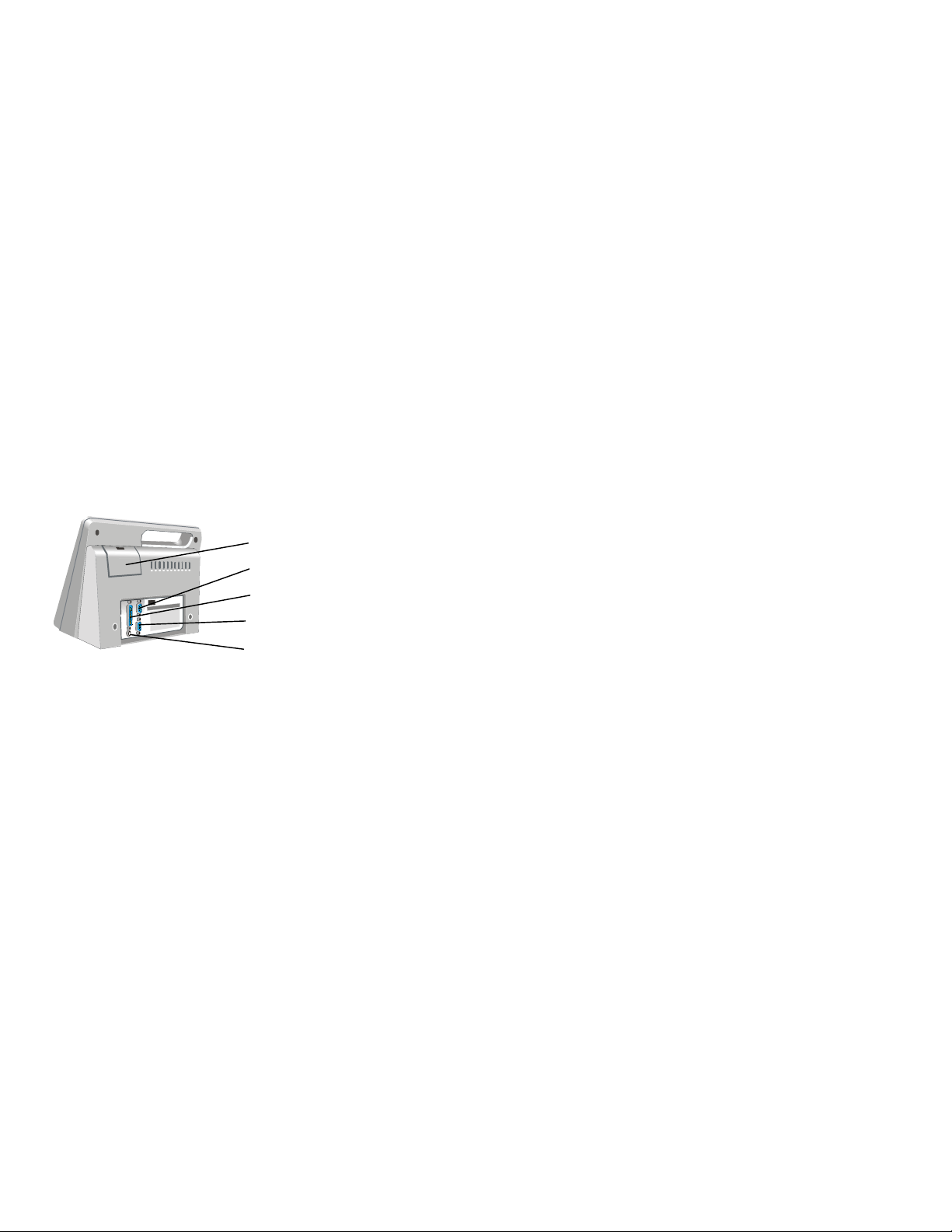
Connecting External Components
An IBM-compatible laboratory computer and a serial or a parallel external printer can be used with the
system. The connector ports for these devices are located at the rear of the instrument (Figure 2).
Important: The power cord must be disconnected and the power to the personal computer and the
printer must be switched OFF while connections are being made.
Printer Paper Door
COM 1 Serial Port
Parallel Printer Port
COM 2 Serial Port
AC/DC Power Module
Connector
Figure 2. Location of Connectors
Connecting a Printer
If a serial printer is used, set the printer communication parameters to 9600 baud with no parity, 8 data
bits and 1 stopbit using XON/XOFF 3-wire software protocol. No special preparation is needed when
connecting a parallel printer. For additional information, contact ITC Technical Service.
1.
Obtain a printer cable (not included). Refer to page 39 for serial printer cable information.
2.
Connect one end of the printer cable to the port marked PRINTER (for a parallel printer) or
COM 1 or COM 2 (for a serial printer) (Figure 2).
3.
Connect the other end of the printer cable to the printer.
4.
Specify use of an external printer (page 19).
6

Connecting a Personal Computer
Printed From ITC Intranet
The system can be connected to a personal computer using a standard NULL modem cable.
1.
Obtain an RS232 cable (provided). Refer to page 39 for cable information.
2.
Connect one end of the cable to the port marked COM 1 or COM 2 (Figure 2).
3.
Connect the other end of the cable to an unused serial communication port on the computer.
Note the location (COM 1 or COM 2) of the port.
4.
Set the COM port location as described on page 19.
Connecting a Bar Code Reader
A bar code reader can be attached to the HEMOCHRON Response for use in entering parameters such as
OID and PID.
Note: Refer to page 39 for information on connecting the bar code reader and configuring the cable.
1.
Connect the cable to the port selected in Set Output Options.
2.
Set the COM port location as described on page 19.
Note: Only one COM port can be designated for a bar code reader at a time.
Charging the Battery
The battery of the system must be charged before the system can be used.
1.
Plug the AC/DC Power Module into an electrical service outlet.
Caution: Ensure that the input voltage requirements of the AC/DC Power Module match the
voltage used in the laboratory.
2.
Connect the AC/DC Power Module cord to the Power connector (Figure 2).
3.
Allow the battery to charge for at least 16 hours.
Note: The AC/DC Power Module can remain connected indefinitely.
Low Battery Warning
The battery supplies power whenever the system is operated without the AC/DC Power Module. The system
will operate for at least eight hours on a fully charged battery.
The amount of charge remaining is displayed, either as a numerical percentage or as a bar indicator
(page 19) whenever the battery is used to operate the system. CHARGE BATTERY is displayed and the battery
power display blinks when the battery power drops to 30 percent of full charge. The system can still be used
until the battery power drops to 10 percent.
BATTERY TOO WEAK TO RUN TESTS is displayed when the battery power drops to 10 percent of full charge.
SHUTDOWN IN XX SECONDS is displayed beginning 30 seconds before the system is automatically shut
down.
Loading Paper in the Internal Printer
Printer paper must be loaded if the internal printer is to be used.
Important: Red lines on the sides of the paper indicate an empty roll. As soon as red lines appear,
replace the roll with a new roll to avoid a paper jam.
1.
Open the paper door and remove the spent roll.
2.
Unroll the end of the new roll and cut off the corners to form a pointed end.
3.
Holding the roll of paper so the pointed end is pointing away from you and up, thread the pointed
end into the paper slot until it appears at the top of the printer.
4.
Grasp the pointed end pull it upwards.
5.
Place the new roll into the printer and close the door.
7

Prewarming
r
Printed From ITC Intranet
The test wells can be prewarmed to 37 °C ±1.0 °C on command. On completion, 3 short beeps are emitted.
Note: Refer to assay package inserts for prewarming requirements.
Automatic Shutdown
When operating from the battery, the system shuts down automatically after 15 minutes of inactivity. This
15-minute interval cannot be changed. When operating from the AC/DC Power Module, the system
automatically shuts down after an interval of inactivity defined by the supervisor.
Note: The factory default setting is 60 minutes.
All stored data is retained after an automatic shutdown.
Test Termination
A test is terminated if clot formation is not detected within 1,500 seconds after starting the test. A FAULT
>1500 message is then displayed and stored in the database, indicating the test result is outside of the
specified range.
Note: Results that are greater than the specified time are beyond the sensitivity range of the test.
They should be repeated immediately and, if confirmed, reported as greater than the maximum time.
A test is automatically terminated if after pressing START a test tube is not inserted into that well within 60
seconds or if a stable magnet is not detected in that well within 75 seconds.
Keypad
Printer Operations
Operator Answe
Keys
Display Panel
Power Indicators
Well Status Indicator LEDs
Number Pad/Option Selector
START
Menu Selections
The use of each of the keys is summarized below:
Key Purpose
START 1, START 2, Switch power ON or OFF. Initiate a test when blood is added to a test tube.
MENU 1, MENU 2 Display the first (press once) or second (press twice) page of the main
menu for Well 1 or Well 2, respectively. Display following page(s) of other
screens.
CANCEL Cancel an operation or return to the previous selection.
PRINT Print results on an external and/or internal printer.
PAPER FEED Advance the printer paper one line.
BACKSPACE (Before entering Yes or No) Undo the previous keypad entry.
0 through 9 Enter PID, OID, PIN (optional), ESV serial number, and QC ranges. Select a
menu option.
YES (ENTER) Save the response to a prompt or the entered ID or PIN.
NO Reject the response to a prompt.
, Left/Right Cursor Positioning.
,
Page Up/Page Down.
8

Display Panel
r
r
p
r
r
p
r
Printed From ITC Intranet
Operations such as running a test and prewarming a well can be carried out simultaneously on both wells.
However, commands, prompts, and test results that appear on the display panel apply to a single well. The
well for which commands are displayed is designated by the position of the divider bar (the bar in which
the time and remaining battery power are displayed) (Figure 3).
Arrows
Divider Ba
Figure 3. Display Panel
Commands and results for Well 1 are shown in the upper portion of the of the display panel, while
commands and results for Well 2 are shown in the lower portion of the display panel (Figure 4).
Well 1
Commands
Divider Ba
Divider Ba
Well 2
Commands
Figure 4. Display of Commands
Press the appropriate MENU key to display a menu of commands for the corresponding well. Press the
appropriate START key to start a test in the corresponding well. During testing and other operations, the
divider bar indicates the well for which results or prompts are displayed (Figure 5).
Well 1 Test
Results and
Divider Ba
Prom
ts
Figure 5. Display of Results
Divider Ba
Well 2 Test
Results and
Prom
ts
9

The arrows designate the operation that will be halted if the CANCEL key is pressed. If an operation is
Printed From ITC Intranet
canceled, the arrows will point to the next operation that can be canceled. If an operation cannot be
canceled, arrows are not displayed.
Note: Pressing CANCEL shuts down a test, removes any related menus, sets the assay to the default
assay, sets the record type to Patient, resets the OID or PIN and resets all lockouts.
Operation for either well can be stopped by ensuring that the arrows point to the display for that well and
then pressing CANCEL.
Note: For example, if PT FWB is run in Well 1, information and results for the test are displayed on
the upper portion of the display panel. Then, if another test is run in Well 2 while PT FWB is being run
in Well 1, the display will show information and results for the second test on the lower portion of the
display panel and arrows will indicate that the Well 2 operation will be stopped if CANCEL is pressed.
Note: During operation, press 1 or 2 to point the arrows towards the display for the corresponding
well. During display of a menu, press a MENU key to display the menu for the corresponding well.
When using the AC/DC Power Module, the display is fully illuminated for the flashlight time specified by the
operator. While running on the battery, the display dims after one minute. Pressing any key or test
completion restores the display.
When the battery is used, the percentage of battery power remaining is displayed either as a numerical
percentage or as a bar indicator, as specified during setting of Output Options.
Indicator LEDs
The indicator LEDs are illuminated as described below:
LED Purpose
Power The system is turned ON.
Charge The AC/DC Power Module is used.
Detect 1/2 The test tube magnet is in the detector zone in Well 1/Well 2.
Heater 1/2 Heat is applied to Well 1/Well 2.
Menus
Note: Some commands (such as Prewarm Well) are specific to a single well and the corresponding
key (MENU 1 or MENU 2) must be used. Other commands (such as System OFF) apply to the entire
system and either key can be used.
Whenever a menu has more than one page of commands, the page symbol is displayed on the right side of
the display. Display subsequent pages by pressing a MENU key. Alternately, press the 0 key to display the
next page of commands or press the 9 key to display the previous page of commands.
Press a MENU key once to display the first page of the main menu (Figure 6):
Figure 6. First Page of the Main Menu
10
Select a command by pressing the corresponding numeral key while the command is displayed. For
Printed From ITC Intranet
example, if a PID or OID/PIN is to be entered using the ID Selects command, press 1.
Press a MENU key twice to display the second page of the main menu (Figure 7):
Figure 7. Second Page of the Main Menu
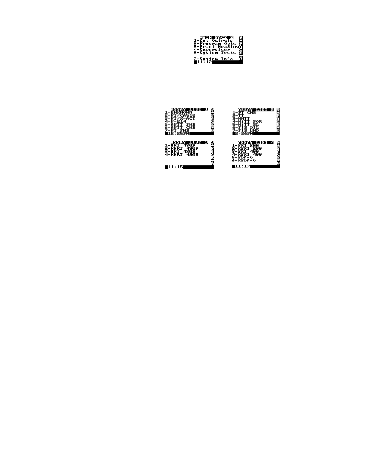
Tests
The test menu is contained on four pages, accessed by selecting the ID Selects command from the first page
of the main menu and then selecting 3 to display the first Test ID page (Figure 8). Press 0 (or a MENU key)
to display following pages, press 9 (or the CANCEL key) to display previous pages.
Figure 8. Test Lists
Note: The test menu may be updated by ITC as new tests are available.
Reagents
Reagents are contained in disposable HEMOCHRON test tubes. The reagents are ready to use.
Note: Refer to the package insert accompanying the HEMOCHRON test tubes for storage and handling
instructions.
ITC test tubes for the HEMOCHRON Response Whole Blood Coagulation System contain a barcode label
imprinted with the test name and expiration. When these tubes are placed in the test well, the instrument
automatically reads this information and selection of the test from the test menu is unnecessary. For
specifying a test, refer to Specifying the Test to be Run on page 22.
SETTING SUPERVISOR OPTIONS
Supervisor options allow the laboratory administrator to configure the system to meet the needs of the
laboratory and operators.
Note: Supervisor options are password protected.
Access to Supervisor Options
The Supervisor Menu is contained on several pages. Access to these menus requires entry of a passcode.
Important: The supervisor passcode is factory set to 0 (for none). Until the supervisor passcode is
set to a value other than zero (0), anyone can access the Supervisor menu by pressing YES. Once the
supervisor passcode is set to a value other than zero, the supervisor menu cannot be accessed unless
the passcode is entered correctly.
Note: If the passcode is lost, contact ITC Technical Service for an interim passcode.
11

To Display the Supervisor Menu:
Printed From ITC Intranet
1.
Display the second page of the main menu.
2.
Press 4 to display the Enter Passcode prompt. Enter the passcode.
3.
Press YES to accept. The first page of the Supervisor menu is displayed.
4.
Press MENU once or twice to display the second or third page of the Supervisor menu.
Note: The next or previous pages can also be displayed by pressing 0 or 9.
Setting the Time
The time that a test is performed is automatically recorded with the test result. Specify the time format prior
to setting the time.
Note: Use a 24-hour or a 12-hour format.
1.
Display the first page of the Supervisor menu.
2.
Press 1. The Time/Date Setup menu is displayed.
3.
Press 1. The Set Time prompt is displayed with the current time.
4.
Enter the correct time using the numeral keys.
5.
Press YES to save the new time.
Note: Pressing CANCEL cancels the procedure without saving the new time.
Setting the Date
The date the test is performed is automatically recorded with the test result.
1.
Display the first page of the Supervisor menu.
2.
Press 1. The Time/Date Setup menu is displayed.
3.
Press 2. The Set Date prompt is displayed with the current date.
4.
Enter the correct date using the numeral keys.
Note: The date can be entered using either a MON/DAY/YEAR or a YEAR/MON/DAY format.
5.
Press YES to save the new date.
Note: Pressing CANCEL cancels the procedure without saving the new date.
Specifying the Time Format
The time can be entered and reported in either 24-hour format or 12-hour format.
1.
Display the first page of the Supervisor menu.
2.
Press 1. The Time/Date Setup menu is displayed.
3.
Press 3. The time formats are displayed.
4.
Press 1 to select the 12-hour clock mode. Press 2 to select the 24-hour clock mode.
5.
Press YES or CANCEL.
Note: The arrow points to the currently selected option.
Specifying the Reported Date Format
The date can be reported in either MON/DAY/YEAR format or YEAR/MON/DAY format.
To Change the Date Format:
1.
Display the first page of the Supervisor menu.
2.
Press 1. The Time/Date Setup menu is displayed.
3.
Press 4. The date formats are displayed.
4.
Press 1 to select the MON/DAY/YEAR mode. Press 2 to select the YEAR/MON/DAY mode.
5.
Press YES or CANCEL.
Note: The arrow points to the currently selected option.
12

Displaying the Clock
Printed From ITC Intranet
The time can be displayed on the separator bar of the display panel.
1.
Display the first page of the Supervisor menu.
2.
Press 5 to display the Clock line. ON will be displayed after the Clock line.
Note: Displaying the clock operates as a toggle. If clock is already specified (displayed as
ON), it can be canceled by pressing 5 again to display OFF.
Specifying Auto Shutdown Time
When operated with the AC/DC Power Module, the maximum time that the instrument can remain inactive
before it automatically shuts down can be specified; this is preset at the factory to 60 minutes.
Note: When the instrument is operated from the battery, it shuts down automatically after 15
minutes, regardless of the specified Auto Shutdown time.
1.
Display the first page of the Supervisor menu.
2.
Press 6 to display the Enter Auto Shutdown Time prompt.
3.
Enter the time (1 to 999 minutes) that the instrument can remain inactive before it will
automatically shutdown. Or, enter 0 to disable this feature.
4.
Press YES to save the new time interval and display the first page of the Supervisor menu.
Specifying the Default Assay
The instrument will automatically identify a test as the default assay if a test has not been otherwise
specified by the barcode on the test tube or by the operator. If an illegible barcode is identified, the test will
be labeled “Unknown”.
1.
Display the first page of the Supervisor menu.
2.
Press 7. The first page of the Assay List is displayed.
3.
Select the desired test. If needed, press 9 or 0 to display another page of the Assay List.
4.
Press YES to save the new default assay.
5.
The Default Assay will appear on the display panel for each well until another test is selected.
Requiring Entry of PID
Entry of a PID can be required before a test can be run.
1.
Display the first page of the Supervisor menu.
2.
Press 2 to display the PID Setup menu:
3.
Press 1 if entry of a PID will be required. Y (YES) will be displayed after Required.
Note: Press the numeral key again to select the alternate choice. If entry of a PID is specified
as required, the message PID Required will appear on the instrument display panel.
Specifying the Required Number of Digits in the PID
The required number of digits that must be entered for PID can be specified.
1.
Display the first page of the Supervisor menu.
2.
Press 2 to display the PID Setup menu.
3.
Press 2 to display the Enter PID Digits prompt. Enter the number of digits.
Note: 0 or 3 to 9 can be entered. If 0 is entered, any number of digits up to 9 can be entered
for PID.
13

Specifying the Length of Time a PID will be Reused
Printed From ITC Intranet
After a PID is entered, it can be displayed as a default entry for a specified number of hours.
1.
Display the first page of the Supervisor menu.
2.
Press 2 to display the PID Setup menu.
3.
Press 3 to display the Enter Reuse Hrs prompt. Enter the number of hours.
Note: 0 to 240 can be entered. If 0 is entered, the entered PID will not be reused.
Requiring Entry of an OID or PIN
1.
Display the first page of the Supervisor menu.
2.
Press 3 to display the OID Setup menu:
3.
Press 1 to display the OID Requirements menu:
4.
Specify whether and how OID entry will be required (only one can be specified):
•
Press 1 if entry of OID or PIN will not be required.
•
Press 2 if entry of OID (any OID) will be required.
•
Press 3 if entry of a valid OID will be required.
•
Press 4 if entry of a PIN will be required.
Note: If entry of an OID or PIN is specified as required, a reminder message will appear on
the instrument display panel. Only the OID is printed with results or stored in the database.
Note: A valid OID is one that is entered on the Edit User Codes list (page 15).
Specifying the Length of Time an OID will be Reused
After an OID is entered, it can be displayed as a default entry for a specified number of hours.
1.
Display the first page of the Supervisor menu.
2.
Press 3 to display the OID Setup menu.
3.
Press 5 to display the Enter Reuse Hrs prompt. Enter the number of hours.
Note: 0 to 240 can be entered. If 0 is entered, the entered OID will not be reused.
If valid PIN is required, reuse is not allowed.
14
 Loading...