

Page 1
PROD. NO. 028112
MOD. NO. IJS2000
Emergency JumpStart and Air Compressor
Operator’s Manual (p.2)
Survolteur et compresseur d’urgence
Manual d’utilisateur ( p.11)
SAVE THIS MANUAL
v060713
v.081203
You will need this manual for safety instructions, operating procedures,
and warranty. Put it and the original sales invoice in a safe, dry place for
future reference.
CONSERVEZ CE GUIDE
Vous aurez besoin de ce guide pour les instructions de sécurité, les
procédures d’utilisation et la garantie. Conservez-le dans un endroit sûr et
sec pour référence future.
Page 2

IMPORTANT SAFETY INSTRUCTIONS
!
!
READ ALL INSTRUCTIONS BEFORE USING THIS TOOL
WARNING!
= Do not connect the black negative clamp to the negative battery terminal.
= Do not expose this unit to rain or moisture.
= Keep this equipment out of the reach of children.
= Improper use of this unit may result in bodily injury such as burns or blindness.
This unit contains a sealed, lead-acid battery that should be kept at full charge.
Recharge this unit when rst received, immediately after each use, and once a
ENGLISH
month if not used.
CAUTION: When using electric tools, machines or equipment, basic safety pre-
cautions should always be followed to reduce the risk of re, electric shock,
and personal injury.
GENERAL SAFETY INSTRUCTIONS
1. KEEP WORK AREA CLEAN. Cluttered areas invite injuries.
2. CONSIDER WORK AREA ENVIRONMENT. Don’t use power tools in damp,
wet, or poorly lit locations. Don’t expose your tool to rain. Keep the work area
well lit. Don’t use tools in the presence of ammable gases or liquids.
3. KEEP CHILDREN AND BYSTANDERS AWAY. All children should be kept
away from the work area. Don’t let them handle machines, tools or extension
cords. Visitors can be a distraction and are difcult to protect from injury.
4. USE THE RIGHT TOOL. Don’t force a small tool or attachment to do the work
of a larger industrial tool. Don’t use a tool for a purpose for which it was not
intended.
5. DO NOT ABUSE THE CORD. Never carry your tool by the cord or pull on the
FRANÇAIS
cord to unplug it. Protect the cord from potential sources of damage: heat, oil
& solvents, sharp edges, or moving parts. Replace damaged cords
immediately.
6. WHEN WORKING OUTDOORS, USE AN OUTDOOR-RATED EXTENSION
CORD. An extension cord rated for outdoor use must be marked “W-A” or “W”.
7. DO NOT EXPOSE ELECTRICAL POWER TOOLS TO MOISTURE. Rain or
wet conditions can cause water to enter the tool and lead to electric shock.
8. ENSURE THE EXTENSION CORD YOU USE IS OF SUFFICIENT GAUGE
FOR ITS LENGTH.
Recommended Minimum Wire Gauge for Extension Cords
Amps
from Tool Nameplate
0 - 5 amps 16 ga. 16 ga. 16 ga. 14 ga. 12 ga. 12 ga.
5.1 - 8 amps 16 ga. 16 ga. 14 ga. 12 ga. 10 ga. Do Not Use
8.1 - 12 amps 14 ga. 14 ga. 12 ga. 10 ga. Do Not Use Do Not Use
12.1 - 15 amps 12 ga. 12 ga. 10 ga. 10 ga. Do Not Use Do Not Use
15.1 - 20 amps 10 ga. 10 ga. 10 ga. Do Not Use Do Not Use Do Not Use
9. STORE IDLE EQUIPMENT. Store equipment in a dry area to inhibit rust. Equip-
ment also should be in a high location or locked up to keep out of reach of
children.
10. DRESS PROPERLY. Don’t wear loose clothing or jewelry; they can be caught in
moving parts. Protective, non-electrically conductive gloves and non-skid footwear are recommended when working. Wear protective hair covering to contain
long hair and keep it from harm.
11. USE EYE PROTECTION. Use a full-face mask if the work you’re doing produces
metal lings, dust or wood chips. Goggles are acceptable in other situations.
Wear a clean dust mask if the work involves creating a lot of ne or coarse dust.
12. DON’T OVERREACH. Keep proper footing and balance at all times. Do not
reach over or across machines that are running.
7.62 m
(25') long
15.24 m
(50') long
22.86 m
(75') long
30.48 m
(100') long
45.72 m
(150') long
60.96 m
(200') long
2
Page 3

IMPORTANT SAFETY INSTRUCTIONS
!
13. MAINTAIN TOOLS WITH CARE. Keep tools sharp and clean for better and safer
performance. Follow instructions for lubricating and safe performance. Follow
instructions for lubricating and changing accessories. Keep handles dry, clean
and free from oil and grease.
14. ALWAYS CHECK AND MAKE SURE TO REMOVE ANY ADJUSTING KEYS
OR WRENCHES from the tool or work surface before turning the tool on. Left
attached, these parts can y off a rotating part and result in personal injury.
15. AVOID UNINTENTIONAL STARTING. Be sure the switch is in the OFF position
before plugging in.
16. DO NOT USE THE TOOL IF IT CANNOT BE SWITCHED ON OR OFF. Have
your tool repaired before using it.
17. DISCONNNECT THE PLUG FROM POWER BEFORE MAKING ANY ADJUSTMENTS. Changing attachments or accessories can be dangerous if the tool
could accidentally start.
18. STAY ALERT. Watch what you are doing & use common sense. Don’t operate
any tool when you are tired.
19. CHECK FOR DAMAGED PARTS. Before using this tool, any part that is damaged should be carefully checked to determine that it will operate properly and
perform its intended function. Check for alignment of moving parts, binding of
moving parts, breakage of parts, mountings, and other conditions that may affect
its operation. Inspect screws and tighten any that are loose. Any part that is dam-
aged should be properly repaired or replaced by an authorized service center
unless otherwise indicated elsewhere in the instruction manual. Have defective
switches replaced by an authorized service center. Don’t use the tool if switch
does not turn it on and off properly.
20. REPLACEMENT PARTS. When servicing, use only identical replacement parts.
21. SERVICE AND REPAIRS should be made by qualied repair technicians at an
authorized repair centre. Improperly repaired tools could cause serious shock or
injury
22. EMPLOYER MUST ENFORCE COMPLIANCE with the safety warnings and all
other instructions contained in this manual.
23. KEEP THIS MANUAL AVAILABLE for use by all people assigned to use this
tool.
ENGLISH
FRANÇAIS
SPECIFIC SAFETY INSTRUCTIONS FOR JUMPSTART
SPECIFIC SAFETY INSTRUCTIONS
WARNING! Risk of Explosive Gases
1. WORKING NEAR A LEAD-ACID BATTERY IS DANGEROUS. Batteries gener-
ate explosive gases during normal operation. Do not face the battery during
connection and stay as far as possible away from the battery being charged.
2. READ AND FOLLOW THE INSTRUCTIONS IN THIS MANUAL AND THOSE
FOR THE VEHICLE’S BATTERY AND ELECTRICAL SYSTEM. Review all
caution markings on these products and on the engine.
3. WEAR EYE PROTECTION AND PROTECTIVE CLOTHING.
4. HAVE PLENTY OF FRESH WATER AND SOAP AT HAND in case battery acid
contacts skin, clothing, or eyes. Avoid touching eyes while working near battery.
If battery acid contacts skin or clothing, wash immediately with soap and water.
If acid enters the eye(s), immediately ood with cold water for at least 10 minutes
and get medical attention as soon as possible.
5. DO NOT SMOKE NOR ALLOW SPARKS NOR FLAME in the vicinity.
6. BE CAUTIOUS WITH METAL TOOLS contacting the vehicle battery. Do not
drop metal tools onto the battery. Contact between metal and the positive battery post may cause a spark, or short-circuit the vehicle battery or some other
electrical component, which in turn may cause electrical system damage or an
explosion.
7. REMOVE METAL PERSONAL ITEMS such as rings, bracelets, chains, or pen-
dants when working near a lead-acid battery. Contact between a metal item and
the positive post on the vehicle can produce a short circuit current high enough
to cause a severe burn.
3
Page 4
SPECIFIC SAFETY INSTRUCTIONS FOR JUMPSTART
!
8. CHARGE LEAD-ACID BATTERIES ONLY. Do not use the Jumpstart for
charging or boosting dry-cell batteries, commonly used for home and portable
appliances, as they may burst and cause injury.
9. DO NOT CHARGE OR BOOST A FROZEN VEHICLE BATTERY.
10. DO NOT ALLOW THE ALLIGATOR CLAMPS TO TOUCH EACH OTHER or to
touch a piece of metal at the same time.
This product has been carefully engineered and manufactured to give you
dependable operation. Please read this manual thoroughly before operating your
new product, as it contains the information you need to become familiar with its
features and obtain the performance that will bring you continued enjoyment for
ENGLISH
many years.
WARNING! The warnings, cautions, and instructions detailed in this manual cannot
cover all possible conditions and situations that occur. It must be understood by
the operator that COMMON SENSE AND CAUTION ARE FACTORS that cannot be built into this product, but MUST BE SUPPLIED BY THE OPERATOR.
FEATURES
= 500 cold-cranking amps boost power and 900 peak amps
= All switches, indicators, and power jacks are located on an up-front convenient
control panel.
= 3 cigarette-lighter power outlets for powering multiple 12 volt devices
= LED battery condition indicators Input charging jack and charging indicator light
= Twin work lights
= Positive (Red) and Negative (Black) colour-coded booster clamps with 4 gauge
cables
= 250 psi compressor with pressure gauge
= Convenient rear storage compartment with door holds:
FRANÇAIS
- 120 volt AC charger for charging from residential power
- 12 volt DC charging cord with cigarette lighter adaptor for in-vehicle charging
- Air hose with quick-connect chuck
- Needle adaptor for balls, 2 other inatables adaptors, fuse, 1 bulb
= Comfortable, pliable carry handle attens to unobtrusive stowed position
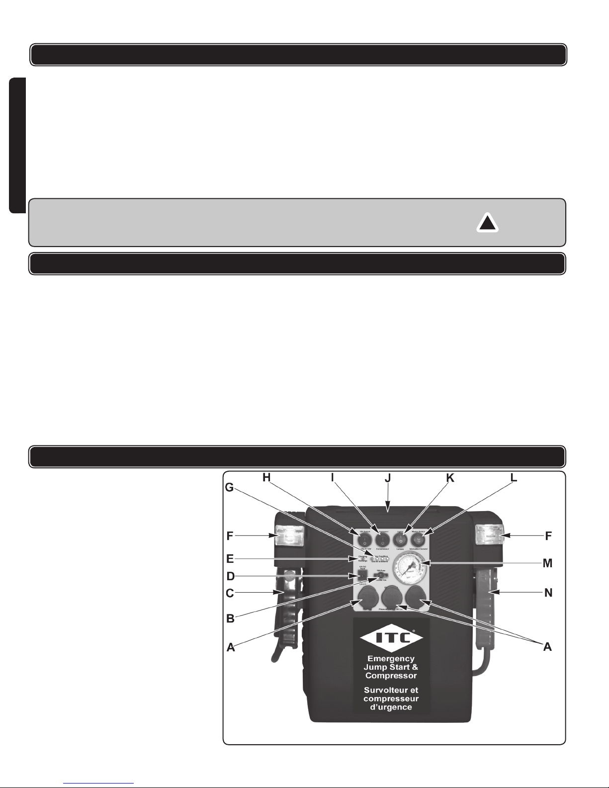
FUNCTIONAL DESCRIPTION
A. 12 volt cigarette-lighter type power outlet
with rubber cap
B. Main unit fuse
C. Negative (black) booster clamp
D. Input charging jack
E. Charging indicator light
F. Work light
G. Battery charge-level indicator lights
H. 12 volt power outlet on/off switch
I. Compressor on/off switch
J. Carry handle
K. Work light on/off switch
L. Master power switch and battery test
button
M. Air compressor pressure gauge
N. Positive (red) battery booster clamp
g.1
4
Page 5
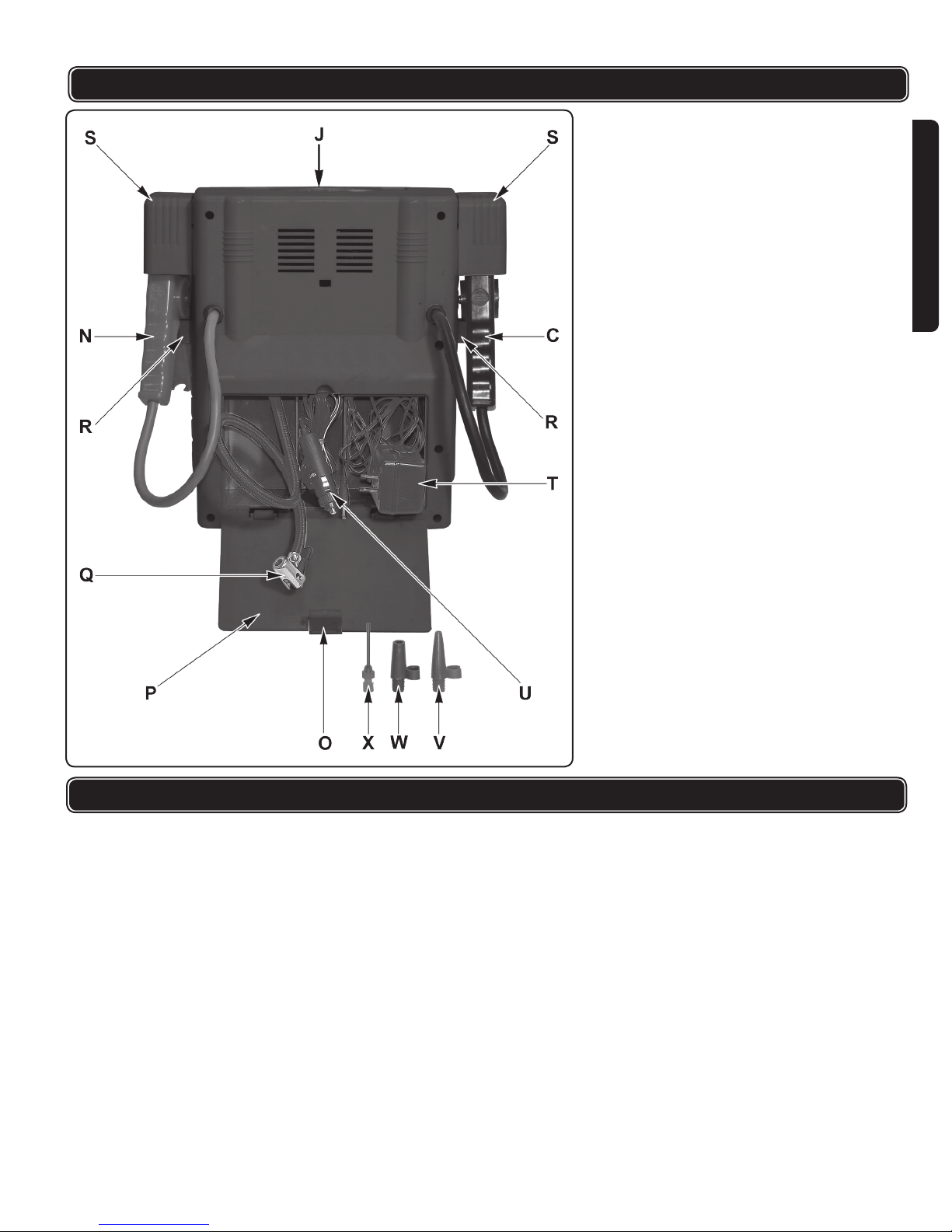
FUNCTIONAL DESCRIPTION
O. Rear compartment locking tab
P. Rear compartment cover
Q. Air hose and nozzle
R. Battery clamp storage hook
S. Battery clamp safety shield
T. AC power adaptor
U. 12 volt DC cigarette lighter adaptor
V. Fine conical inator nozzle
W. Blunt conical inator nozzle
X. Ball ination needle
ENGLISH
FRANÇAIS
g.2
SPECIFICATIONS
= Power: Built-in 18 amp/hour non-spillable sealed lead-acid rechargeable
battery
= DC Output: 12 volt
= Current: provides up to 900 peak amps, 500 cranking amps boost rate
= Compressor: 250 psi (1723 kPa)
= Air hose: 580 mm (2') air hose with quick-connect thumb lock chuck
= Work Lights: 12 volt 3 watt bulbs
= AC charger: 120 volt AC ~ 12 volt DC 500 mA c-UL-us charger with 1.75 m
(69") cable
= DC charger: 12 volt DC 1.4 m (56") charging cord with cigarette lighter
adaptor for in-vehicle charging
= Fuse: 15 amp fast-acting (blue) automotive blade-type (ATC-15 or
equivalent)
= Temperature: Operating range: -20o to 60oC (-4o to 140o F)
25oC (77o F) optimum
= Dim. (LWH): 330 mm x 190 mm x 305 mm (13" x 7.5" x 12")
= Weight: 6.2 kg (13.6 lb.)
5
Page 6

RECHARGING PROCEDURES
!
CHARGING THE JUMPSTART POWER SUPPLY
BATTERY
This unit has a built-in lead acid battery. Although the Jumpstart system arrives
partially-charged from the factory, it should be fully charged - at least 12 hours-
before initial use.
TO RECHARGE WITH RESIDENTIAL POWER AND THE
AC POWER ADAPTOR:
1. Be sure the master power switch (L, g.1) on the control panel is off (the side
ENGLISH
of the switch marked “O” is depressed).
2. Remove the AC power adaptor with its DC power plug (T, g.2) from the rear
storage compartment.
3. Plug the AC adaptor into any 120 volt AC wall outlet and the other end into the
input charging jack (D, g.1) of the Jumpstart System.
4. The charging indicator light (E, g.1) will illuminate to indicate the Jumpstart
is being charged.
5. Full charging may take approximately 20 hours.
6. When the master power switch is turned on (the side of the switch marked “I” is
depressed), the battery charge-level indicator lights (G, g.1) on the control
panel will illuminate:
• Two green lights– full charge
• One green light– good charge
• Amber – weak: recharge
• Red – dead: recharge
TO RECHARGE IN YOUR VEHICLE WITH THE DC POWER CORD:
1. Be sure the master power switch (L, g 1) on the control panel is off (the side
of the switch marked “O” is depressed).
FRANÇAIS
2. Be sure the vehicle is running.
3. Remove the 12 volt DC cigarette lighter adaptor, charging plug and cable
(U, g.2) from the rear storage compartment.
4. Plug the 12 volt DC cigarette adaptor charging plug into your vehicle’s cigarette
lighter socket.
5. Insert the DC power plug at other end of the cable into the input charging jack
(D, g 1) of the Jumpstart system.
6. The charging indicator light (E, g 1) will illuminate to indicate the Jumpstart
is being charged. You can now recharge your Jumpstart for as long as your
vehicle is running.
7. Full charging may take approximately 11 hours.
8. When the master power switch is turned on (the side of the switch marked “I” is
depressed), the battery charge-level indicator lights (G, g.1) on the control
panel will illuminate:
• Two green lights– full charge
• One green light– good charge
• Amber – weak: recharge
• Red – dead: recharge
NOTE:
=Do not drive while the Jumpstart is connected to- and charging from- the ciga-
rette lighter or power port of your vehicle.
=Some vehicles’ cigarette lighters and 12 volt power ports do not operate un-
less the ignition switch is in the necessary position.
WARNING!
=Do not continuously charge the Jumpstart for more than 36 hours.
=Use only the power cords that were provided with the IJS2000 Jumpstart unit
when charging, otherwise damage to the unit may result.
NOTE: Keep battery power topped up, ready for emergencies. Unlike some re-
chargeable batteries, frequent charging will not harm and will in fact improve
the performance of the internal battery.
6
Page 7

RECHARGING PROCEDURES
!
!
!
WARNING! The Jumpstart power supply should never be kept in a totally dis-
charged state for an extended period. Damage due to sulfation could be permanent, resulting in continuing and irreparable poor performance. When not in
use, recharge once a month with the charger.
BATTERY STATUS
1. Turn on (depress the side of the switch marked “I”) the master power switch on
the control panel.
2. The battery charge level indicator LED lights on the control panel will illuminate
to indicate the amount of charge remaining in the Jumpstart System. When you
turn off the switch, the battery charge level indicator LED lights will go out.
• When the battery is fully charged, all four LEDs, including the two green
indicator lights, will illuminate.
• Red, amber and one green light indicates a 75 % charge.
• If only the red and yellow lights are illuminated, battery is at 50% capacity
and will operate most 12 volt accessories, but is inadequate for boosting
function. Unit should be recharged as soon as possible.
• When only the red indicator light is illuminated the battery is low and must
be recharged before further use.
OPERATING PROCEDURES
JUMPSTART AN ENGINE
WARNING! The Jumpstart must be fully charged to start an engine.
ENGLISH
FRANÇAIS
If your vehicle’s battery is too weak to start your car, you can use the Jumpstart
power supply to start it.
1. Check the vehicle manual for special procedures and prohibitions with particular regard for sensitive on-board electronics and computers which could be
damaged by the jumpstarting procedure.
2. Make sure the vehicle’s accessories, i.e.: lights, AC, heater, radio, etc., are all
turned off.
3. For maximum power, make sure all switches on the Jumpstart control panel are
turned off (depress the side of the switches marked “O”).
WARNING!
= Wear eye protection and protective clothing.
= Do not attempt to charge a battery with frozen electrolyte.
= The booster clamps are not switched by the master switch and are always live.
Do not allow the clamps to touch each other or to each touch a common piece
of metal.
= Working near a lead-acid battery is dangerous. Batteries generate explosive
gases during normal operation. Do not face the battery during connection and
stay as far as possible away from the battery being charged.
4. Place the Jumpstart unit on a at surface within the engine compartment so it
is stable and close enough to reach the battery’s positive terminal with the red
booster clamp. Ensure that the unit cannot fall into moving belts, fan blades,
or the like when the car shakes as it starts.
5. To remove the clamps from the safety holsters, lift them up, move them outward sideways, and lower them.
6. Securely connect the positive (red) battery booster clamp (N, g.1&2),
marked +, to the corresponding positive (+) terminal of the dead vehicle battery. Do not allow the positive (+) red battery booster clamp to contact any
part of the vehicle other than the positive terminal of the battery. This can
cause a momentary short in the battery or electrical system and result in expensive damage to vehicle electronic equipment.
7. Securely connect the negative (black) booster clamp (C, g.1&2), marked -,
to a grounding point such as the metal of the engine or vehicle chassis, as far
away from the battery as possible.
7
Page 8

OPERATING PROCEDURES
!
!
!
!
WARNING! DO NOT connect the black negative (-) booster clamp to the nega-
tive terminal of your battery. Connecting to the battery’s negative terminal
can cause sparking in close proximity to the battery’s natural explosive gases,
leading to a dangerous explosion. Once the cables are connected, DO NOT
wiggle the clamps around trying to make a better connection. This can cause
sparking and is an explosion hazard.
7. Start your vehicle.
WARNING! Be careful of moving parts such as belts, pulleys, or fan blades in the
ENGLISH
FRANÇAIS
engine compartment that can cause injury.
8. Disconnect the black negative clamp rst. Return it to the safety shield marked
(-) for negative. Insert it, lifting it up and moving it over the hook in the side of
the housing.
9. Disconnect red positive clamp. Return it to the safety shield marked (+) for
positive.
NOTE: If your vehicle does not start within 10 seconds, allow the Jumpstart
system’s internal battery to cool for 3 minutes before attempting to start the
vehicle again.
NOTE: If your vehicle battery is so dead that its ignition light does not come on,
let the Jumpstart remain connected to the battery for 10-20 minutes before
attempting to start the vehicle.
CAUTION: DO NOT attempt to operate 12 volt accessories from the Jumpstart
system while trying to start a vehicle.
POWER SUPPLY FOR 12 VOLT ACCESSORIES
The three 12 volt cigarette-lighter type power outlets (A, g.1) on the control
panel will operate most 12 volt accessories with a draw of 10 amps or less through
cigarette-lighter adaptors. When fully charged, the Jumpstart system will supply
power to a 10 amp accessory for approximately one hour, a 6 amp accessory for
approximately two hours, and a 4 amp accessory for approximately three hours.
1. Make sure the 12 volt power outlet on/off switch (H, g.1) on the control
panel is in the “OFF” position (the side of the switch marked “O” is depressed).
2. Remove the protective rubber cover from the 12 volt cigarette-lighter-type
power outlets (A, g.1) and plug in your 12 volt accessory’s cigarette-lighter
adaptor.
3. Turn the 12 volt power outlet on/off switch (H, g.1) to the “ON” position
(depress the side of the switch marked “I”).
NOTE: The 12 volt cigarette-lighter-type power outlets (A, g 1) are protected
by a fuse that prevents damage to the unit in case of short circuit or overdraw
current.
1. If the fuse blows, turn the master power switch (H, g.1) off (depress the side
of the switch marked “O”).
2. Disconnect the 12 volt accessory.
3. Replace the blown fuse with another 15 amp of identical type.
4. Have the 12 volt accessory checked for possible defects before re-connecting.
AIR COMPRESSOR
CAUTION: Do not over-inate! Check the manufacturer’s air pressure require-
ments for what you are inating and watch the pressure gauge on the front of
the Jumpstart. This compressor is capable of putting out 250 psi, but it is a
light-duty unit; it does not produce a large volume of air, so it may take some
time to inate larger objects.
1. To use the compressor, open the rear compartment cover (P, g.2) located on
the back of the unit by depressing the rear compartment locking tab
(O, g.2).
2. Pull out the air hose and nozzle (Q, g.2).
3. Make sure the nozzle lever is in the up position, in line with the metal chuck’s
body (g 2 shows the lever folded down).
8
Page 9

OPERATING PROCEDURES
!
!
!
4. Place the nozzle over the valve stem of the tire and fold down the lever so it is
parallel with the hose to lock the nozzle into position.
5. Turn the compressor on/off switch (I, g.1) to the “ON” position (depress the
side of the switch marked “I”).
6. Monitor the air compressor pressure gauge (M, g.1) while inating.
7. When desired pressure has been reached, turn compressor off (depress the
side of the switch marked “O”) with the compressor on/off switch (I, g.1)
8. Flip the nozzle lever back into the up position and disconnect the hose.
9. For inating other articles, select the appropriate inator nozzle (V, W, X; g.2)
and insert it into the hose nozzle. Fold the lever down to lock the adaptor in
place.
10. Inate the object as above.
NOTE: For athletic balls, moisten needle before inserting it into the ball’s valve.
For other pneumatic articles, the nozzle should be inserted into the valve and
held tightly to insure a good seal.
CAUTION: Allow the air compressor to cool down approximately 5 minutes be-
tween ination of each car tire. Whether lling large-volume items like tires or
other inatables, the compressor should not be run continuously for more than
10 minutes; after which it should be allowed to cool for 5 minutes. Over-use
could cause over-heating and motor failure.
WORK LIGHT
The twin work lights (F, g.1) are switched by the work light on/off switch
(K, g.1) located at the top of the front panel.
1. Turn on the master power switch (L, g.1) (depress the side of the switch
marked “I”).
2. Move the work light on/off switch (K, g.1) to the “on” position (depress the
side of the switch marked “I”).
ENGLISH
FRANÇAIS
MAINTENANCE
WARNING!
= Do not open the Jumpstart. There are no user-serviceable parts in this unit.
= Do not use the air compressor as a breathing device
= Do not allow compressed air near the body. Introducing pressurized air into
open orices, through skin, or open wounds could cause death.
FUSE REPLACEMENT
1. The 15 amp main unit fuse (B, g.1) is an ATC-15 or equivalent
blue automotive blade-type fuse.
2. To check the fuse, pull it from its socket in the control panel.
3. Check the lament between the two blades.
4. If it is melted,
5. Make sure master power switch (H, g.1) is off (the side of the switch marked
“O” is depressed).
6. Replace the fuse with an identical fast-acting 15 amp ATC-15 or equivalent blue
automotive blade-type fuse.
CAUTION: Never replace a fuse with one that has a higher amperage rating.
DISPOSAL
The IJS2000 contains a SEALED, non-spill able LEAD-ACID BATTERY. It MUST
BE disposed of properly. Contact local recycling authorities for information on
disposal according to local laws.
Risk of explosion: DO NOT INCINERATE.
9
Page 10

PARTS LIST
Please refer to Schematic Drawing on page 21.
O.
N
1 Switch 4
2 Steel pin 2
3 Fuse 1
4 Clear lens 2
5 Lamp 2
ENGLISH
6 Reector 2
7 Lamp clip & PCB 2
8 Clamp cover (Left) 1
9 Clamp 2
10 Air pump 1
11 Air pump mounting plate 1
12 Anti-vibration ring 4
13 Back shell 1
14 Back cover compartment 1
Description Qty.
O.
N
15 Vibration absorber 1
16 Air pump mounting clamp 1
17 Clamp cover (Right) 1
18 Battery 1
19 Front shell 1
20 Carry handle 1
21 PCB 1
22 Cigarette plug & PCB 1
23 Face plate 1
24 DC cap 3
25 Cable
26 Air hose 1
Description Qty.
WARRANTY
ITC branded power tools, air nailers staplers and compressors are designed for
use in DIY (do-it-yourself), light or intermittent duty, semi-professional applications.
They are not intended for use in professional, production, industrial or continual
FRANÇAIS
use applications.
2
ITC makes every effort to ensure that its products meet high quality and durability
standards and are warranted for two years against manufacturers’ faults and
defects for a period of two years from the date of purchase to the original owner.
ITC will REPAIR OR REPLACE (at our discretion) merchandise deemed by the
company to be defective, provided that it is has not been misused, abused, altered,
or repaired by anyone other than an authorized repair centre.
Please consult the ITC catalogue or your nearest ITC distributor to determine those
products that are covered by our over-the counter warranty. Any ITC tool that fails
during normal use and within the specied warranty period and qualies for overthe counter warranty must be returned to its point of purchase for replacement
or credit. Any item not listed as over-the-counter warranty must be shipped,
prepaid freight, to an authorized repair depot accompanied by a copy of the
invoice specifying the date that the item was purchased. Returned tools that are
not accompanied by a proof of purchase (Copy of Invoice) will not be repaired or
replaced under warranty.
This warranty does not extend to normal wear or consumable parts such as brad
and staple gun driver blades, grinding discs, saw blades, driver bits, electric motor
brushes, worn chords, etc. It also does not apply to ITC tools used in professional,
production, industrial or continual use applications.
For a listing of the authorized repair centers please refer to the ITC catalogue.
10
Page 11

IMPORTANTES DIRECTIVES DE SÉCURITÉ
!
!
LISEZ TOUTES LES CONSIGNES AVANT D’UTILISER CET OUTIL
MISE EN GARDE!
= Ne branchez pas la pince négative de couleur noire à la borne négative de la
batterie.
= N’exposez pas l’appareil à la pluie ni à l’eau.
= Gardez cet équipement hors de la portée des enfants.
= Une mauvaise utilisation de cet appareil peut entraîner des blessures, des
brûlures ou la cécité.
Cet appareil contient une batterie d’accumulateur au plomb qui doit être
constamment chargé à bloc.
Rechargez cet appareil sur réception, immédiatement après chaque utilisation,
et une fois par mois s’il n’est pas utilisé.
MISE EN GARDE : Certaines consignes de sécurité de base doivent toujours être
respectées lors de l’utilisation d’outils, de machine ou d’équipement élec-
triques an de réduire les risques de blessure.
CONSIGNES DE SÉCURITÉ GÉNÉRALES
1. GARDEZ VOTRE ESPACE DE TRAVAIL PROPRE. Les endroits encombrés
sont sources de blessures.
2. PRENEZ VOTRE AIRE DE TRAVAIL EN CONSIDÉRATION. N’utilisez pas
d’outil électrique dans un endroit humide ou mouillé. Veillez à ce que votre outil
soit toujours à l’abri de la pluie. Éclairez bien votre espace de travail. N’utilisez
pas d’outils en présence de liquides ou de gaz inammables.
3. ÉLOIGNEZ LES ENFANTS ET LES OBSERVATEURS. Aucun enfant ne
devrait se trouver dans l’espace de travail. Ne les laissez pas manipuler les
machines, les outils ou les rallonges électriques. Les visiteurs peuvent vous
distraire et il est difcile de les prémunir contre les blessures.
4. UTILISEZ L’OUTIL APPROPRIÉ. N’exigez pas d’un petit outil ou accessoire
qu’il accomplisse le travail d’un outil industriel de plus gros calibre. N’utilisez
pas un outil pour une n imprévue lors de sa conception.
5. PRENEZ SOIN DU CORDON D’ALIMENTATION. Ne transportez jamais votre
outil par le cordon d’alimentation. Ne tirez pas sur le cordon pour le débrancher. Gardez le cordon à l’abri des sources de dommages potentielles : la chaleur, l’huile, des rebords coupants ou des pièces en mouvement. Remplacez
immédiatement les cordons endommagés.
6. LORSQUE VOUS TRAVAILLEZ À L’EXTÉRIEUR, UTILISEZ UNE RALLONGE ÉLECTRIQUE HOMOLOGUÉE POUR L’EXTÉRIEUR. Une rallonge
électrique homologuée pour l’utilisation à l’extérieur doit être identiée par les
lettres « W-A » ou « W ».
7. VEILLEZ À CE QUE LES OUTILS ÉLECTRIQUES SOIENT TOUJOURS À
L’ABRI DE L’HUMIDITÉ. Sous la pluie ou dans des conditions humides, de
l’eau pourrait pénétrer l’outil et causer une électrocution.
8. ASSUREZ-VOUS QUE LA RALLONGE ÉLECTRIQUE UTILISÉE EST DE
CALIBRE SUFFISANT POUR SA LONGUEUR.
Calibre minimum recommandé pour les cordons de rallonge
Indice d'intensité
(ampères)
0 - 5 amp. cal.16 cal.16 cal.16 cal.14 cal.12 cal.12
5,1 - 8 amp. cal.16 cal.16 cal.14 cal.12 cal.10 Ne pas utiliser
8,1 - 12 amp. cal.14 cal.14 cal.12 cal.10 Ne pas utiliser Ne pas utiliser
12,1 - 15 amp. cal.12 cal.12 cal.10 cal.10 Ne pas utiliser Ne pas utiliser
15,1 - 20 amp. cal.10 cal.10 cal.10 Ne pas utiliser Ne pas utiliser Ne pas utiliser
9. RANGEZ LES OUTILS INUTILISÉS. Rangez l’équipement dans un endroit sec
an d’éviter la formation de rouille. L’équipement doit aussi être élevé ou verrouillé an de le garder hors de la portée des enfants.
10. PORTEZ DES VÊTEMENTS APPROPRIÉS. Ne portez pas de vêtements am-
Longeur
de 7,62 m
(25 pi)
Longeur
de 15,24 m
(50 pi)
Longeur
de 22,86 m
(75 pi)
Longeur
de 30,48 m
(100 pi)
Longeur
de 45,72 m
(150 pi)
ENGLISH
FRANÇAIS
Longeur
de 60,96 m
(200 pi)
11
Page 12

CONSIGNES DE SÉCURITÉ GÉNÉRALES
!
ples ou de bijoux tombant : ils pourraient se coincer dans les pièces mobiles.
Le port de gants de protection non conducteurs d’électricité et de chaussures
antidérapantes est recommandé pour le travail. Portez un couvre-chef de protection an de contenir les longs cheveux et de les garder à l’abri.
11. PORTEZ UN PROTECTEUR OCULAIRE. Si le travail à effectuer produit des
éclats métalliques, de la poussière ou des copeaux de bois, portez un masque
intégral. Des lunettes de protection conviennent aux autres situations. Portez
un masque antipoussières si le travail doit produire beaucoup de poussière
ne ou épaisse.
12. NE VOUS ÉTIREZ PAS INDÛMENT. Garder vos pieds au sol et conservez
votre équilibre en tout temps. Ne vous étirez pas vers ou par-dessus des ma-
ENGLISH
chines en fonctionnement.
13. ENTRETENEZ VOS OUTILS AVEC SOIN. Gardez vos outils aiguisés et
propres an d’obtenir une meilleure performance et une plus grande sécurité.
Suivez les consignes de performance et de sécurité. Suivez les consignes de
lubrication et de changement des accessoires. Gardez les poignées au sec,
propres et exemptes d’huile et de graisse.
14. ASSUREZ-VOUS TOUJOURS D’AVOIR RETIRÉ TOUTE CLÉ DE RÉGLAGE
de l’outil ou de la surface de travail avant de mettre l’outil en marche. S’ils sont
laissés en place, ces pièces peuvent se décoller d’une pièce en rotation en
entraîner des blessures.
15. ÉVITEZ LES DÉMARRAGES INOPINÉS. Assurez-vous le bouton
d’alimentation est à la position d’arrêt avant de brancher l’outil.
16. N’UTILISEZ PAS L’OUTIL SI SON INTERRUPTEUR NE PERMET PAS DE
LE METTRE EN MARCHE OU DE L’ÉTEINDRE. Avant d’utiliser votre outil,
faites-le réparer.
17. DÉBRANCHEZ LA FICHE DE L’ALIMENTATION AVANT DE PROCÉDER À
TOUT RÉGLAGE. Un changement d’accessoire peut s’avérer dangereux s’il
existe la possibilité que l’outil démarre inopinément.
18. SOYEZ VIGILANT. Regardez ce que vous faites et servez-vous du gros bon
FRANÇAIS
sens. N’utilisez aucun outil lorsque vous êtes fatigué.
19. VÉRIFIEZ QUE LES PIÈCES NE SONT PAS ENDOMMAGÉES. Avant
d’utiliser cet outil, toute pièce endommagée doit être vériée avec soin an
d’établir si l’appareil peut fonctionner correctement et accomplir la tâche pour
laquelle il a été conçu. Vériez l’alignement des pièces mobiles, le serrage des
pièces mobiles, l’absence de bris, le montage ainsi que l’absence de tout autre
facteur qui puisse affecter le fonctionnement de l’appareil. Vériez l’état des
vis et resserrez les vis lâches. Une pièce endommagée doit être réparée ou
remplacée correctement par un centre de service autorisé, à moins d’une indication contraire gurant ailleurs dans ce mode d’emploi. Faites remplacer tout
interrupteur défectueux par un centre de service autorisé. N’utilisez pas l’outil
si son interrupteur ne permet pas de le mettre en marche ou de l’éteindre.
20. PIÈCES DE REMPLACEMENT. N’utilisez que des pièces de rechange identiques.
21. L’ENTRETIEN ET LES RÉPARATIONS doivent être effectués par les techniciens qualiés d’un centre de service autorisé. Des outils réparés de façon
inadéquate peuvent causer une électrocution ou des blessures graves.
22. LES EMPLOYEURS DOIVENT S’ASSURER DU RESPECT des consignes de
sécurité et de toutes les autres consignes de ce mode d’emploi.
23. METTEZ CE MODE D’EMPLOI À LA DISPONIBILITÉ de toute personne
devant utiliser cet outil.
CONSIGNES PARTICULIÈRES AU SURVOLTEUR
MISE EN GARDE! Risque de gaz explosifs.
1. IL EST DANGEREUX DE TRAVAILLER PRÈS D’UNE BATTERIE
D’ACCUMULATEUR AU PLOMB. Les batteries génèrent des gaz explosifs
dans le cadre de leur fonctionnement normal. Ne vous mettez pas face à la
batterie pendant le branchement. Restez aussi loin que possible d’une batterie
en chargement.
2. LISEZ ET SUIVEZ LES DIRECTIVES DE CE MODE D’EMPLOI, AINSI QUE
CELLES DE LA BATTERIE ET DU SYSTÈME ÉLECTRIQUE DU VÉHICULE.
Passez en revue toutes les étiquettes de sécurité de ces produits et du moteur.
12
Page 13

CONSIGNES PARTICULIÈRES AU SURVOLTEUR
!
3. PORTEZ DES VÊTEMENTS ET DES LUNETTES DE PROTECTION.
4. GARDEZ UNE BONNE QUANTITÉ D’EAU ET DE SAVON PRÈS DE VOUS,
au cas où l’acide de la batterie entrerait en contact avec votre peau, vos vêtements ou vos yeux. Évitez de vous toucher les yeux lorsque vous travaillez
près d’une batterie. Si de l’acide de la batterie entre en contact avec votre
peau ou vos vêtements, lavez-les immédiatement à l’eau savonneuse. Si de
l’acide pénètre vos yeux, rincez-les à l’eau froide immédiatement pendant au
moins 10 minutes et consultez un médecin dès que possible.
5. NE FUMEZ PAS ET NE LAISSEZ PAS DE FLAMMÈCHE OU DE FLAMME
s’approcher.
6. VEILLEZ À CE QUE LES OUTILS MÉTALLIQUES n’entrent pas en contact
avec la batterie du véhicule. Ne laissez pas tomber d’outil métallique sur la
batterie. Tout contact entre le métal et une borne positive de batterie peut
entraîner une ammèche, un court-circuit dans la batterie du véhicule ou dans
une autre composante électrique, qui à son tour peut causer un dommage au
système électrique ou une explosion.
7. RETIREZ TOUS BIJOU MÉTALLIQUE tel bague, bracelet, collier, montre et
autre bijou lorsque vous travaillez près d’une batterie. Tout contact entre un
article de métal et la borne positive de la batterie du véhicule peut entraîner un
court-circuit assez élevé pour causer des brûlures sévères.
8. NE CHARGEZ QUE DES BATTERIES D’ACCUMULATEURS AU PLOMB.
N’utilisez pas le survolteur pour charger ou survolter des batteries à pile sèche,
généralement utilisées dans les appareils domestiques et portatifs. Elles pour-
raient exploser et causer des blessures.
9. NE CHARGEZ PAS ET NE SURVOLTEZ PAS UNE BATTERIE DE VÉHICULE SI ELLE EST GELÉE.
10. NE LAISSEZ PAS LES PINCES DE CONTACT SE TOUCHER ou toucher à
un morceau de métal en même temps.
Ce produit a été conçu et fabriqué avec soin dans le but de vous offrir une
performance able. Veuillez lire ce guide attentivement et au complet d’utiliser
votre nouveau produit. Il contient les renseignements dont vous avez besoin pour
devenir familier avec ses fonctions et pour obtenir une performance qui saura vous
satisfaire pour les années à venir.
MISE EN GARDE! Les avertissements, mises en garde et consignes de ce guide
ne peuvent couvrir toutes les situations et conditions possibles. L’opérateur
doit reconnaître que le BON SENS ET LA PRÉCAUTION ne peuvent être intégrés au produit, mais qu’IL DOIT LUI-MÊME EN FAIRE PREUVE.
ENGLISH
FRANÇAIS
CARACTÉRISTIQUES
= Tension de survoltage de 500 ampères au démarrage et 900 ampères maxi-
mum
= Tous les interrupteurs, témoins et prises de tension sont situés sur un panneau
de commande pratique à l’avant de l’appareil.
= 3 prises à briquet pour alimenter de multiples appareils de 12 volts
= Témoins à DEL de l’état de la batterie
= Prise d’entrée de chargement et témoin de chargement
= Éclairage de travail double
= Pinces de survoltage positive (rouge) et négative (rouge) à code de couleur
avec câbles de calibre 4
= Compresseur de 250 psi avec manomètre
= Compartiment de rangement arrière pratique avec couvercle contenant :
- Chargeur de 120 volts CA pour le chargement à l’aide de la tension do-
mestique
- Cordon de chargement de 12 volts CC avec adaptateur de briquet pour le
chargement à l’intérieur du véhicule
- Tuyau pneumatique avec mandrin à branchement rapide
- Adaptateur d’aiguille pour ballons et 2 autres adaptateurs de gonement
= La poignée de transport confortable et pliable s’aplatit pour une position de
rangement discrète.
13
Page 14

DESCRIPTION DES FONCTIONS
A. Sortie d’alimentation de 12 volts de type
ENGLISH
briquet avec capuchon de caoutchouc
B. Fusible de l’unité principale
C. Pince de survoltage négative (noire)
D. Prise d’entrée de chargement
E. Témoin de chargement
F. Lampe de travail
G. Témoins de chargement de la batterie
H. Bouton d’alimentation de la prise de 12
volts
I. Bouton d’alimentation du compresseur
J. Poignée de transport
K. Bouton d’alimentation de la lampe de
travail
L. Interrupteur principal et bouton de test de
la batterie
M. Jauge de pression d’air du compresseur
N. Pince de survoltage positive (rouge)
O. Onglet de fermeture du compartiment ar-
rière
FRANÇAIS
P. Couvercle du compartiment arrière
Q. Tuyau pneumatique et bec
R. Crochet de rangement de la pince de bat-
terie
S. Écran de sécurité de la pince de batterie
T. Adaptateur de tension CA/CC
U. Adaptateur de briquet de 12 volts CC
V. Bec de gonement conique n
W. Bec de gonement conique arrondi
X. Aiguille de gonement de ballon
g.1
14
g.2
Page 15

FICHE TECHNIQUE
= Intensité : Batterie d’accumulateur au plomb antidéversement,
scellée et intégrée, de 18 A/h
= Sortie CC : 12 volts
= Intensité : Jusqu’à 900 ampères maximum,
taux de survoltage de 500 ampères au démarrage
= Compresseur : 250 psi (1 723 kPa)
= Tuyau pneumatique : 580 mm (2 pi) avec mandrin à branchement rapide
= Lampes de travail : Ampoules de 12 volts, 3 watts
= Chargeur CA : Transformateur/chargeur de 120 volts CA ~ 12 volts CC
500 mA c-UL-us avec câble de 1,75 m (69 po)
= Chargeur CC : Cordon de chargement de 12 volts CC de 1,4 m (56 po)
avec adaptateur de briquet pour le chargement à
l’intérieur du véhicule
= Fusible : Fusible (bleu) à lame à action rapide pour automobile de
15 A, ATC-15 ou équivalent
= Dimensions (LlH) : 332 mm x 183 mm x 306 mm
(13,1 po x 7,2 po x 12,1 po)
= Poids : 6,9 kg (15.2 lb.)
ENGLISH
PROCÉDURES DE RECHARGEMENT
CHARGEMENT DE LA BATTERIE
D’ALIMENTATION DU SURVOLTEUR
Cet appareil est doté d’une batterie d’accumulateur au plomb intégrée. Bien que
le système de survoltage est partiellement chargé à sa sortie d’usine, il doit être
complètement chargé pendant au moins 12 heures avant son utilisation initiale.
POUR RECHARGER AVEC L’ALIMENTATION DOMESTIQUE À L’AIDE DE
L’ADAPTATEUR CA :
1. Assurez-vous que l’interrupteur principal (L, g. 1) du panneau de com-
mande est à la position d’arrêt (« O »).
2. Retirez l’adaptateur CA et la che d’alimentation DC (T, g. 2) du comparti-
ment de rangement arrière.
3. Branchez l’adaptateur CA dans une prise murale de 120 volts CA. Branchez
son autre extrémité dans la prise d’entrée de chargement (D, g. 1) du sys-
tème de survoltage.
4. Le témoin de chargement (E, g. 1) s’illumine pendant le chargement du sur-
volteur.
5. La durée d’une charge complète est d’environ 20 heures.
6. Lorsque l’interrupteur principal est mis à la position d’alimentation (« I »), les
témoins de niveau de chargement de batterie (G, g. 1) s’illuminent sur le
panneau de commande :
• Deux témoins verts : Charge complète
• Un témoin vert : Charge convenable
• Ambre – faible : Rechargez
• Rouge – déchargé : Rechargez
FRANÇAIS
POUR RECHARGER AVEC VOTRE VÉHICULE À L’AIDE LA RALLONGE ÉLEC-
TRIQUE CC :
1. Assurez-vous que l’interrupteur principal (L, g. 1) du panneau de com-
mande est à la position d’arrêt (« O »).
2. Assurez-vous que le moteur du véhicule tourne.
3. Retirez la che de chargement de l’adaptateur de briquet CC et le câble (U,
g. 2) du compartiment de rangement arrière.
4. Branchez la che de chargement de l’adaptateur de briquet CC dans la prise
de briquet de votre véhicule.
5. Insérez la che d’alimentation CC de l’autre extrémité du câble dans la prise
d’entrée de chargement (D, g. 1) du système de survoltage.
6. Le témoin de chargement (E, g. 1) s’illumine pendant le chargement du survolteur. Vous pouvez à présente recharger votre survolteur, tant que le moteur
15
Page 16

PROCÉDURES DE RECHARGEMENT
!
!
!
de votre véhicule tourne.
7. La durée d’une charge complète est d’environ 11 heures.
8. Lorsque l’interrupteur principal est mis à la position d’alimentation (« I »), les
témoins d’état de la batterie (G, g. 1) s’illuminent sur le panneau de commande :
• Deux témoins verts : Charge complète
• Un témoin vert : Charge convenable
• Ambre – faible : Rechargez
• Rouge – déchargé : Rechargez
ENGLISH
REMARQUE :
=Ne conduisez pas votre véhicule lorsque votre survolteur est branché – en en
chargement – sur le port de briquet ou d’alimentation de votre véhicule.
=Certains ports de briquet et d’alimentation de 12 volts ne fonctionnent pas à
moins que le démarreur ne soit à la position adéquate.
MISE EN GARDE!
=Ne chargez pas le survolteur pendant une période de plus de 36 heures contin-
ues.
=N’utilisez que les cordons d’alimentation fournis avec le survolteur IJS2000
pour le chargement, sans quoi vous risqueriez d’endommager l’appareil.
REMARQUE : Gardez la charge de la batterie à son maximum, prêt en cas
d’urgence. Contrairement à certaines batteries rechargeables, un chargement
fréquent n’endommagera pas votre batterie interne : en fait, un chargement
fréquent en améliorera la performance.
MISE EN GARDE! L’alimentation du survolteur ne doit jamais être en mode de
FRANÇAIS
déchargement complet pendant une longue période. Les dommages dus à
la sulfatation pourraient être permanents, ayant pour résultat une mauvaise
performance continuelle et irréparable. Lorsque l’appareil n’est pas utilisé,
rechargez la batterie une fois par mois à l’aide du chargeur.
ÉTAT DE LA BATTERIE
1. Mettez l’interrupteur principal du panneau de commande à la position
d’alimentation (« I »).
2. Les témoins à DEL de chargement de la batterie du panneau de commande
s’illuminent pour indiquer le temps de chargement restant au système de survoltage. Lorsque vous mettez l’interrupteur à la position d’arrêt, les témoins à
DEL de chargement de la batterie s’éteignent.
• Lorsque la batterie est complètement chargée, tous les témoins, y compris
les deux témoins verts, s’illuminent.
• Les témoins rouge, ambre et vert (un seul) indique une charge à 75 %,
• Si seuls les témoins rouge et jaune sont illuminés, la batterie est à 50 %
de sa capacité et permettra de faire fonctionner la plupart des accessoires
de 12 volts. Elle ne pourra toutefois être utilisée pour le survoltage.
L’appareil doit être rechargé aussitôt que possible.
• Si seul le témoin rouge est illuminé, la batterie est faible et doit être
rechargée avant toute utilisation.
PROCÉDURES D’UTILISATION
SURVOLTAGE D’UN MOTEUR
MISE EN GARDE! Le survolteur doit être pleinement chargé pour faire démarrer
un moteur.
Si la batterie de votre véhicule est trop faible pour faire démarrer votre véhicule,
vous pouvez utiliser l’alimentation du survolteur pour le faire démarrer.
1. Consultez les procédures et les interdictions spéciales gurant dans le manuel
du véhicule. Portez une attention particulière aux directives reliées aux tableaux de bord électroniques et aux ordinateurs pouvant être endommagés par
la procédure de survoltage.
16
Page 17

PROCÉDURES D’UTILISATION
!
!
!
!
2. Assurez-vous que les accessoires du véhicule sont éteints : éclairage, climati-
sation, chauffage, radio, etc.
3. Pour une puissance maximale, assurez-vous que tous les interrupteurs du panneau de commande du survolteur sont à la position d’arrêt (« O »).
MISE EN GARDE :
= Portez des vêtements et des lunettes de protection.
= Ne chargez pas une batterie dont un électrolyte est gelé.
= Les pinces de survoltage sont toujours conductrices. Ne laissez pas les pinces
se toucher ou toucher à un morceau de métal en même temps.
= Il est dangereux de travailler près d’une batterie d’accumulateur au plomb. Les
accumulateurs génèrent des gaz explosifs dans le cadre de leur fonctionnement
normal. Ne vous mettez pas face à l’accumulateur pendant le branchement.
Restez aussi loin que possible d’un accumulateur en chargement.
4. Posez l’appareil de survoltage sur une surface plane, à l’intérieur du compartiment du moteur. Assurez-vous qu’il soit stable et à une distance permettant
d’atteindre la borne positive de la batterie à l’aide de la pince de survoltage
rouge. Assurez-vous que l’appareil ne pourra pas tomber sur les courroies, les
lames de ventilation ou autre pièce mobile au moment où le démarrage fera
bouger le véhicule.
5. Pour enlever les pinces des écrans de sécurité, soulevez-les vers le haut et
déplacez-les à l’extérieur pour les décrocher, et les abaissent alors.
6. Branchez bien la pince de survoltage positive (+) rouge (N, g.1 et 2) à la
borne positive (+) correspondante de la batterie déchargée du véhicule. Évitez
que la pince de survoltage positive (+) rouge ne touche à toute autre pièce
du véhicule, autre que à la borne positive de la batterie. Cette situation pourrait entraîner un court-circuit momentané dans la batterie ou dans le système
électrique, causant des dommages coûteux à l’équipement électronique du
véhicule.
7. Branchez bien la pince de survoltage négative (-) noire (C, g.1 et 2) à un
point de mise à la terre, comme le métal du moteur ou le châssis du véhicule,
aussi loin que possible de la batterie.
MISE EN GARDE : NE BRANCHEZ PAS la pince négative (-) de couleur noire
à la borne négative de la batterie. Le branchement à la borne négative de la
batterie peut causer des ammèches près des gaz naturels explosifs de la batterie et entraîner une explosion dangereuse. Une fois les câbles branchés, ne
secouez pas les pinces dans le but d’effectuer un meilleur branchement. Cela
pourrait causer des ammèches, puis une explosion.
7. Démarrez votre véhicule.
MISE EN GARDE : Faites attention aux pièces mobiles, telles les courroies,
poulies ou lames de ventilation, se trouvant dans le compartiment du moteur :
elles pourraient vous blesser.
8. Débranchez d’abord la pince négative noire. Remettez-la dans son écran de
sécurité, qui porte la marque (-) pour « négative ». Insérez-la dans l’écran de
sécurité et montez-la sur la crochet à la côté de la boitier.
9. Débranchez ensuite la pince positive rouge. Remettez-la dans son écran de
sécurité, qui porte la marque (+) pour « positive ».
REMARQUE : Si votre véhicule ne démarre pas en 10 secondes, laissez la bat-
terie interne du système de survoltage refroidir pendant 3 minutes avant de
tenter un nouveau démarrage du véhicule.
ENGLISH
FRANÇAIS
REMARQUE: Si la batterie de votre véhicule est trop faible pour allumer le témoin
de démarrage, branchez l’appareil de survoltage à la batterie pendant 10 à
20 minutes avant de tenter à démarrer la véhicule.
MISE EN GARDE : NE FAITES PAS fonctionner d’accessoires de 12 volts sur le
système de survoltage pendant que vous tentez de faire démarrer un véhicule.
17
Page 18

PROCÉDURES D’UTILISATION
!
ALIMENTATION POUR ACCESSOIRES DE
12 VOLTS
Les sorties d’alimentation de 12 volts de type briquet (A, g. 1) du panneau de
commande permettent de faire fonctionner la plupart des accessoires de 12 volts,
à un débit de 10 ampères ou moins, à l’aide des adaptateurs de briquet. Lorsqu’il
est chargé à bloc, le survolteur peut alimenter un accessoire de 10 ampères
pendant environ une heure, un accessoire de 6 ampères pendant environ deux
heures et un accessoire de quatre ampères pendant environ trois heures.
1. Assurez-vous que le bouton d’alimentation de la prise de 12 volts (H, g. 1)
ENGLISH
du panneau de commande est à la position d’arrêt (« O »).
2. Retirez le capuchon de protection en caoutchouc des sorties d’alimentation
de 12 volts de type briquet (A, g. 1) et branchez votre accessoire de 12
volts dans l’adaptateur de briquet.
3. Mettez le bouton d’alimentation de la prise de 12 volts (H, g. 1) à la posi-
tion d’alimentation (« I »).
REMARQUE : Les sorties d’alimentation de 12 volts de type briquet (A, g. 1)
sont protégées par un fusible. Ce fusible prévient les dommages pouvant être
causés par l’appareil en cas de court-circuit ou d’une surcharge de courant.
1. Si le fusible grille, mettez l’interrupteur principal (L, g. 1) à la position d’arrêt («
O »).
2. Débranchez l’accessoire de 12 volts.
3. Remplacez le fusible grillé par un autre fusible de 15 ampères de type identique.
4. Avant de le rebrancher, faites vérier votre accessoire de 12 volts pour voir s’il
présente une défectuosité.
COMPRESSEUR D’AIR
FRANÇAIS
MISE EN GARDE : Ne gonez pas trop! Vériez les exigences du fabricant en
matière de pression d’air pour l’article à goner. Surveillez le manomètre situé
à l’avant du survolteur. Le compresseur peut produire 250 psi, mais il s’agit
d’un appareil de faible puissance. Ne produisant pas un gros volume d’air, il
se peut que certains objets plus gros soient longs à goner.
1. Pour utiliser le compresseur, ouvrez le couvercle du compartiment arrière (P,
g. 2), situé à l’arrière de l’appareil, en appuyant sur son onglet de fermeture
(O, g. 2).
2. Retirez le tuyau pneumatique et le bec (Q, g. 2).
3. Assurez-vous que le levier du bec est en position élevée, en ligne avec le
corps du mandrin métallique (g. 2 : levier en position abaissée).
4. Placez le bec sur la tête de la valve du pneu et abaissez le levier parallèlement
au tuyau an de l’immobiliser.
5. Mettez le bouton d’alimentation du compresseur (I, g. 1) à la position
d’alimentation (« I »).
6. Surveillez le manomètre du compresseur d’air (M, g. 1) pendant le gon-
age.
7. Lorsque la pression désirée est atteinte, éteignez le compresseur (position « O
») à l’aide de son bouton d’alimentation (I, g.1).
8. Remettez le levier du bec en position élevée et débranchez le tuyau.
9. Pour goner d’autres articles, choisissez le bec de gonement approprié (V, W,
X, g. 2) et insérez-le dans le bec du tuyau. Abaissez le levier pour immobiliser
l’adaptateur.
10. Gonez l’article en suivant les directives ci-dessus.
REMARQUE : Pour les ballons de sport, humectez l’aiguille avant de l’insérer
dans la valve du ballon. Pour les autres articles pneumatiques, le bec doit
être inséré dans la valve et maintenu fermement en place an d’assurer une
bonne étanchéité.
18
Page 19

PROCÉDURES D’UTILISATION
!
!
!
MISE EN GARDE : Laissez le compresseur d’air refroidir pendant environ 5 min-
utes entre le gonage de chaque pneu de voiture. Lorsque vous gonez des
articles volumineux, comme des pneus ou autres articles gonables, le compresseur ne doit pas fonctionner en mode continu pendant plus de 10 minutes.
Après 10 minutes, laissez-le refroidir pendant 5 minutes. Une surutilisation
pourrait entraîner la surchauffe et causer une panne de moteur.
LAMPE DE TRAVAIL
Les lampes de travail double (F, g. 1) sont allumées et éteintes à l’aide de leur
bouton d’alimentation (K, g. 1), situé sur le dessus du panneau avant.
1. Mettez l’interrupteur principal (L, g. 1) à la position d’alimentation (« I »).
2. Mettez le bouton d’alimentation de l’éclairage (K, g. 1) à la position
d’alimentation (« I »).
ENTRETIEN
MISE EN GARDE :
= N’ouvrez pas le survolteur. L’appareil ne contient aucune pièce pouvant être
réparée par l’utilisateur.
= N’utilisez pas le compresseur d’air comme un respirateur.
= Ne dirigez pas l’air comprimé vers le corps. L’introduction d’air comprimé dans
des orices ouverts, à travers la peau ou sur les blessures ouvertes peut entraîner la mort.
REMPLACEMENT DU FUSIBLE
1. Le fusible principal de 15 ampères de l’appareil (B, g. 1) est un fusible bleu
à lame ATC-15 pour automobile ou équivalent.
2. Pour vérier le fusible, retirez-le de sa prise sur le panneau de commande.
3. Vériez le lament entre les deux lames.
4. S’il a fondu,
5. Assurez-vous que l’interrupteur principal du survolteur est à la position d’arrêt
(« O »).
6. Remplacez le fusible avec un fusible bleu à lame à action rapide ATC-15 pour
automobile ou un équivalent.
MISE EN GARDE : Ne remplacez jamais un fusible avec un fusible d’ampérage
plus élevé.
ENGLISH
FRANÇAIS
MISE AUX REBUTS
Le IJS2000 CONTIENT une BATTERIE D’ACCUMULATEUR AU PLOMB
antidéversement ÉTANCHE. Elle DOIT ÊTRE éliminée correctement. Contactez
les autorités de recyclage pour les informations relatives à la mise aux rebuts
réglementaire.
Risque d’explosion : NE PAS INCINÉRER.
19
Page 20

LISTE DES PIÈCES
S’il vous plaît, référer au dessin schématique à la page 21.
O.
N
1 Interrupteur 4
2 Goupille en acier 2
3 Fusible 1
4 Lentille 2
5 Ampoule 2
ENGLISH
6 Réecteur 2
7 Douille et carte de circuit 2
8 Écran de sécurité de la pince gauche 1
9 Pince de survoltage 2
10 Compresseur 1
11 Plaque de xation du compresseur 1
12 Anneau amortisseur de vibrations 4
13 Boitier arrière 1
14 Couvercle du compartiment arrière 1
Description Qté.
GARANTIE
O.
N
15 Amortisseur de vibrations 1
16 Fixation du compresseur 1
17 Écran de sécurité de la pince droite 1
18 Batterie d’accumulateurs 1
19 Boitier avant 1
20 Poignée de transport 1
21 Carte de circuit 1
22 Douille allume-cigarette et carte de circuit 1
23 Dalle 1
24 Capuchon d’allume-cigarette 3
25
26 Tuyau pneumatique 1
Description Qté.
Câble 2
Les produits de marque ITC, tels que les machines-outils, les marteaux agrafeurs
et les compresseurs sont conçues pour les bricoleurs aux ns d’utilisation légère
ou à action intermittente et semi-professionnel. L’intention d’usage n’est pas pour
FRANÇAIS
l’industrie professionnelle, de production, industriel ou usage continuel.
ITC fait tout les efforts de s’assurer que leurs gammes de produits rencontre les
exigences de haute qualité et durabilité. Les produits bricoleurs ITC sont garantis
contre la défectuosité de fabrication pour une période de 2 ans de la date d’achat
du premier occupant. Seulement les produits bricoleurs ITC qui font défauts par
suite d’un usage normal et pendant la période de garantie spéciée ci-dessous,
seront RÉPARÉS OU REMPLACÉS au gré de ITC. La présente garantie ne
s’applique cependant pas aux défectuosités découlant d’un usage impropre ou
abusif, d’une usure anormale ou de modications effectuées hors de l’usine.
S.V.P, consulter le catalogue pour obtenir la liste des produits qui font partie de
la garantie échange au comptoir. Lorsque le produit est admis à la garantie au
comptoir, il doit être retourné au point de vente. Si le produit ne se trouve pas
sur cette liste, il doit être retourné franco de port à un centre de service autorisé
par JET accompagné de la facture indiquant la date d’achat. Il n’y aura aucune
réparation sans la preuve d’achat.
Cette garantie ne s’accorde pas aux pièces consommables telles que les lames
pour les pousse-tocs d’agrafeuses et d’outils Brad, les meules, les brosses pour
moteur électrique, etc. ainsi que les outils usés par l’industrie professionnelle, de
production, industriel ou usage continuel.
An d’obtenir une che des centres de service autorisé s.v.p. consulter le catalogue
ITC.
20
Page 21

SCHEMATIC DRAWING / SCHÉMA
ENGLISH
FRANÇAIS
21
 Loading...