

ITC HEMOCHRON Signature Elite Operator's Manual

1
HEMOCHRON
Whole Blood Microcoagulation System
Operatorʼs Manual
English
TABLE OF CONTENTS
INTENDED USE.......................................................................................... 2
SUMMARY AND EXPLANATION .............................................................. 2
PRINCIPLES OF OPERATION................................................................... 3
DESCRIPTION ............................................................................................ 5
IMPORTANT LABELS AND SYMBOLS ..................................................11
SPECIFICATIONS .................................................................................... 13
PREPARING THE INSTRUMENT ............................................................ 14
STARTING THE INSTRUMENT ...............................................................26
RUNNING A TEST ....................................................................................27
QUALITY CONTROL (QC) .......................................................................36
OPERATING PRECAUTIONS ..................................................................38
LIMITATIONS ........................................................................................... 39
RESULTS MANAGEMENT ...................................................................... 39
COMMUNICATION WITH A PC OR NETWORK ..................................... 46
CONFIGURATION MANAGER................................................................. 48
MASTER FILE MAINTENANCE ............................................................... 69
CONFIGURATION MANAGER UTILITIES............................................... 70
TROUBLESHOOTING .............................................................................. 75
SERVICE AND MAINTENANCE ..............................................................79
SAFETY STANDARDS............................................................................. 80
INDEX ....................................................................................................... 82
This manual is published by International Technidyne Corporation (ITC) for use with the HEMOCHRON Signature
Elite Whole Blood Microcoagulation System.
Questions or comments regarding the contents of this manual can be directed to the address at the back of this
manual or to your ITC representative.
ITC, HEMOCHRON and HEMOCHRON Signature Elite are registered trademarks of International Technidyne
Corporation in the United States and other jurisdictions.
ITC, ReportMaker, idms, HEMOCHRON and HEMOCHRON Signature Elite are trademarks of International
Technidyne Corporation throughout the world.
Celite® is registered trademark of Celite Corporation. Microsoft® and Windows® are registered trademarks of Microsoft
Corporation.
©2006. This document is the copyright of ITC and must not be copied or reproduced in any form without prior consent.
ITC reserves the right to make technical improvements to this equipment and documentation without prior notice as
part of a continuous program of product development.
CAUTION: This manual provides safety instructions for instruments equipped with class 1 or class 2
barcode scanner lasers. Please refer to the back panel of the instrument to identify the class of laser and
follow appropriate instructions provided in this manual.

2
INTENDED USE
The HEMOCHRON Signature Elite® Whole Blood Microcoagulation System is a battery-operated, hand-held
instrument that performs individual point-of-care coagulation tests on fresh or citrated whole blood. These tests
include: Activated Clotting Time (ACT+ and ACT-LR), Activated Partial Thromboplastin Time (APTT and APTT
Citrate), and Prothrombin Time (PT and PT Citrate). The system is intended to be used only with test cuvettes that
are available from ITC.
Data management capabilities are included with the instrument. These capabilities include storage of up to 600
patient results and 600 quality control results, designation of quality control levels, tagging of test results with
date and time, entry of Patient ID and/or Operator ID or Operator PIN, and printing of results.
HEMOCHRON® Configuration Manager software is included. This software allows the user to connect a
personal computer to the instrument and perform system configuration functions using the fast and convenient
Microsoft® Windows® user interface. HEMOCHRON ReportMaker™ software, provided separately, allows the
user to connect a personal computer to an instrument and perform various data management and data
reporting functions.
For in vitro Diagnostic Use.
SUMMARY AND EXPLANATION
Events that lead to formation of a blood clot are simplified in coagulation theory into two interactive
coagulation cascades that are referred to as the intrinsic and the extrinsic pathways.
The clotting factors involved in these pathways are numbered I through V and VII through XIII. The intrinsic
pathway begins with the contact activation of factor XII and, through the interaction of several coagulation
factors, results in the conversion of soluble fibrinogen to insoluble fibrin strands. The extrinsic pathway is
initiated through the interaction of tissue factor with factor VII. Platelets, essential co-factors in this reaction,
provide the platelet phospholipid surface on which coagulation reactions occur.
Activated Clotting Time (ACT+ and ACT-LR), Activated Partial Thromboplastin Time (APTT and APTT Citrate),
and Prothrombin Time (PT and PT Citrate) tests are general coagulation screening tests that are used to
measure the functionality of the blood coagulation cascade. The ACT test is the method of choice for
monitoring heparin therapy during cardiac surgery and PCI. Fresh whole blood is added to an activator
(Celite®, silica, kaolin, or glass particles), and then timed for the formation of a clot. The type of activator used
will affect the degree of prolongation of the ACT to a given heparin dose.
The HEMOCHRON® Jr. ACT+ test uses a mixture of silica, kaolin, and phospholipids as an activator to create a
rapid and highly sensitive alternative to existing ACT tests. This test demonstrates linearity at heparin
concentrations ranging from 1.0 to 6.0 units of heparin per mL of blood, and it is not affected by high dose
aprotinin therapy.
The HEMOCHRON Jr. ACT-LR test uses a Celite activator due to its excellent heparin sensitivity. The test
demonstrates linearity at heparin concentrations up to 2.5 units of heparin per mL of blood. The test is not
intended for use with aprotinin therapy.
The HEMOCHRON Jr. APTT test measures the intrinsic coagulation pathway and involves all coagulation factors
except factors VII and III (tissue factor). The APTT test improves the PTT test through use of a contact
activating substance, which standardizes activation of Factor XII to provide a more precise and sensitive assay
for low level heparin monitoring. The HEMOCHRON Jr. APTT test is formulated to provide optimal heparin
sensitivity at heparin concentrations up to 1.5 units of heparin per mL of blood.
The HEMOCHRON Jr. APTT Citrate test performs the same measurement as the APTT test, using a citrated
whole blood sample.

3
The HEMOCHRON Jr. PT test measures the extrinsic coagulation pathway and is sensitive to coagulation factors
VII, X, V, II, and fibrinogen. PT results may be abnormal in patients with liver disease or Vitamin K deficiency.
The test is widely used to monitor oral anticoagulant therapy. The PT test is a unitized test system utilizing a
highly sensitive thromboplastin for improved specificity and sensitivity.
The HEMOCHRON Jr. PT Citrate test performs the same measurement as the PT test, using a citrated whole
blood sample.
Note: HEMOCHRON Configuration Manager V3.0 or higher is required and is included with the
HEMOCHRON Signature Elite instrument.
PRINCIPLES OF OPERATION
The HEMOCHRON Signature Elite Whole Blood Microcoagulation System provides many features for ease of
use and reliability, including a patented clot detection system, a data storage module, interfaces for a laboratory
computer and/or printer, a streamlined user-interface panel, and an integrated barcode scanner.
The system measures whole blood clotting times using HEMOCHRON Jr. disposable single-use cuvettes. Each
cuvette contains all of the reagents necessary for a specified test.
The operator inserts a cuvette for the test into the instrument and then (if desired) enters information about the
sample or scans the information from a barcode using the integral barcode scanner. After the cuvette has
warmed to 37 °C ±1.0 °C, the instrument beeps, signaling the operator that a blood sample can be added to the
cuvette and the test started.
The operator then places a drop of blood in the sample well of the cuvette and presses the START key. The
instrument measures the required volume of blood and automatically moves it into the cuvette test channel,
where it is mixed with reagents. The remainder of the blood sample, not needed for testing, is automatically
drawn out of the sample well and into an enclosed waste channel on the cuvette.
After mixing with the reagent, the sample is moved back and forth at a predetermined rate within the test
channel and monitored for clot formation. The test channel is maintained at 37 °C ±1.0 °C during the test.
The rate of movement of the sample is monitored by a series of LED optical detectors that are aligned with the
test channel. When the blood clots, the flow of the blood sample within the test channel is impeded, reducing its
rate of flow between the optical detectors.
This reduction in flow below a predetermined value signals to the instrument that a clot has formed. The
instrument also emits an audible beep when clot formation occurs, indicating the end of the test. An internal
timer measures the elapsed time between the start of the test and the clot formation. During the test, the whole
blood clotting time (in seconds) is displayed.
APTT and APTT Citrate results are displayed as plasma equivalent (PE) values, PT and PT Citrate results are
displayed as the International Normalized Ratios (INR) and PE values, and ACT+ and ACT-LR results are
displayed as Celite ACT equivalent time.
The results will remain on the display while the cuvette remains in the instrument.
The result can be automatically printed along with the time and date the test was run, the Patient ID, Operator
ID, and other information, if entered. The result is also saved in an internal database. Up to 600 patient test
results and 600 quality control test results can be stored in the instrument for later printing or downloading.
Individual HEMOCHRON Signature Elite instruments can be customized so that designated quality control tests
must be performed whenever a specified period of time has elapsed and so that information for cuvettes and
liquid controls can be included in test records. The instruments can also be configured so that only authorized
operators can operate the system and/or operators cannot perform certain functions such as deleting test
results from the instrument database. These and other configuration options are entered using HEMOCHRON
Configuration Manager Software on a personal computer.

4
Definitions and Terms
The following acronyms and abbreviations are used in this manual, instrument screens, and printouts:
ACT
Activated Clotting Time
APTT
Activated Partial Thromboplastin Time
CVlot
Cuvette Lot Number
DB
Database
EQC
Electronic Quality Control (System Verification)
HCM
HEMOCHRON Configuration Manager
INR
International Normalized Ratio
idms
Integrated Data Management System
LQC
Liquid Quality Control
OID
Operator Identification Number
PID
Patient Identification Number
PIN
Operator Personal Identification Number
POCC
Point of Care Coordinator
PT
Prothrombin Time
QC
Quality Control
QClot
Quality Control Lot Number
TQC
Temperature Quality Control
5
DESCRIPTION
The HEMOCHRON Signature Elite instrument is a hand-held device. It contains a test chamber which warms
a test cuvette to the required temperature, and it performs all operations to measure the clotting time of a
whole blood sample after it is placed in the test cuvette and the test is started by the operator.
Operator instructions are shown on the display panel, and the operator enters commands and information
using the keypad. When the test is completed, the results are shown on the display panel and stored in system
memory for printing or downloading.
The instrument includes a barcode scanner for reading of barcode labels.
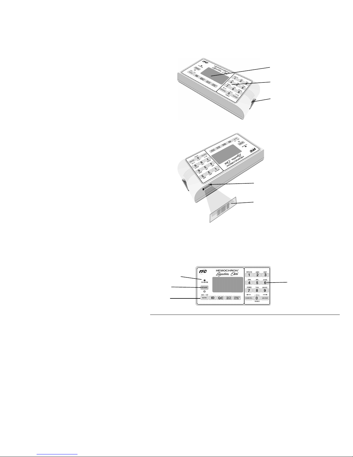
Keypad
The front panel contains a keypad with various action keys as well as a number pad. The operator uses the
keypad to select a command or enter information.
Action keys display a menu of commands according to the label on the key. For example, the PRINT/SCAN key
displays printing commands and enables scanning. Number pad (or option) keys are used to enter characters
for IDs or numbers for selection of commands.
Note: The 0 (zero) key is used as both a numeral key and an action key.
Key
Purpose
START
Turn on the instrument or turn off instrument.
Initiate a test after the test cuvette has reached 37 °C ±1.0 °C and the sample is added.
barcode scanner
(laser aperture)
barcode label
number pad/
option keys
charge indicator
START key
action keys
display panel
keypad
test chamber

6
PRINT/SCAN
Print results on an external printer for the last test result, patient database,
quality control database, or all test results for a specified patient.
Test the printer.
Enter a customized header.
Print instrument system information.
Scan a barcode ID when Enter PID, Enter OID, Enter PIN, Enter CVLot, Enter
QCLot, or Scan Lot is displayed.
NOTE
Select a laboratory-defined note (from nine choices programmed via HEMOCHRON
Configuration Manager) for entry into the record for the current test.
Toggle between alphabetic (ABC) and numeric (123) characters when Enter
PID, Enter OID, Enter PIN, Enter CVLot, or Enter QCLot is displayed.
ID
Enter a Patient ID or Operator ID.
QC
Specify that the test being run is a normal (level 1) control or an abnormal
(level 2) control.
(For QC Lockouts) Display the length of time remaining before Quality Control
testing for a particular test must be successfully completed.
Initiate an EQC (Electronic Quality Control) test.
DATABASE
Display the number of patient or QC test results that are currently stored in the
instrument and the number of additional test results that can be stored.
Display results of the stored patient or QC tests.
Delete patient or QC records.
Initiate POCT-1A communication.
0 through 9
Select a menu option.
Enter information (e.g., a Patient ID, an Operator ID, cuvette lot number, QC lot
number, a time, or a date).
Display the main menu by pressing the Zero key when no tests are running and no
menu is active.
CANCEL
Cancel an operation and return to the previous state.
ENTER
Accept an entry (e.g., a Patient ID, an Operator ID, a time, or a date).
Display Panel
The instrument communicates with the operator by means of the display panel. For example, Add Sample and
Press Start are alternately displayed after a test cuvette reaches temperature:
and
The display is illuminated to enhance visibility in low light conditions. To conserve power during battery
operation, the display is not illuminated when the test well is empty or when a test is running. The display is
momentarily illuminated after a key is pressed or when results of a completed test are displayed. While a test is
running, the display can be momentarily illuminated by pressing the CANCEL key, the ENTER key, or any
numeric key.
7
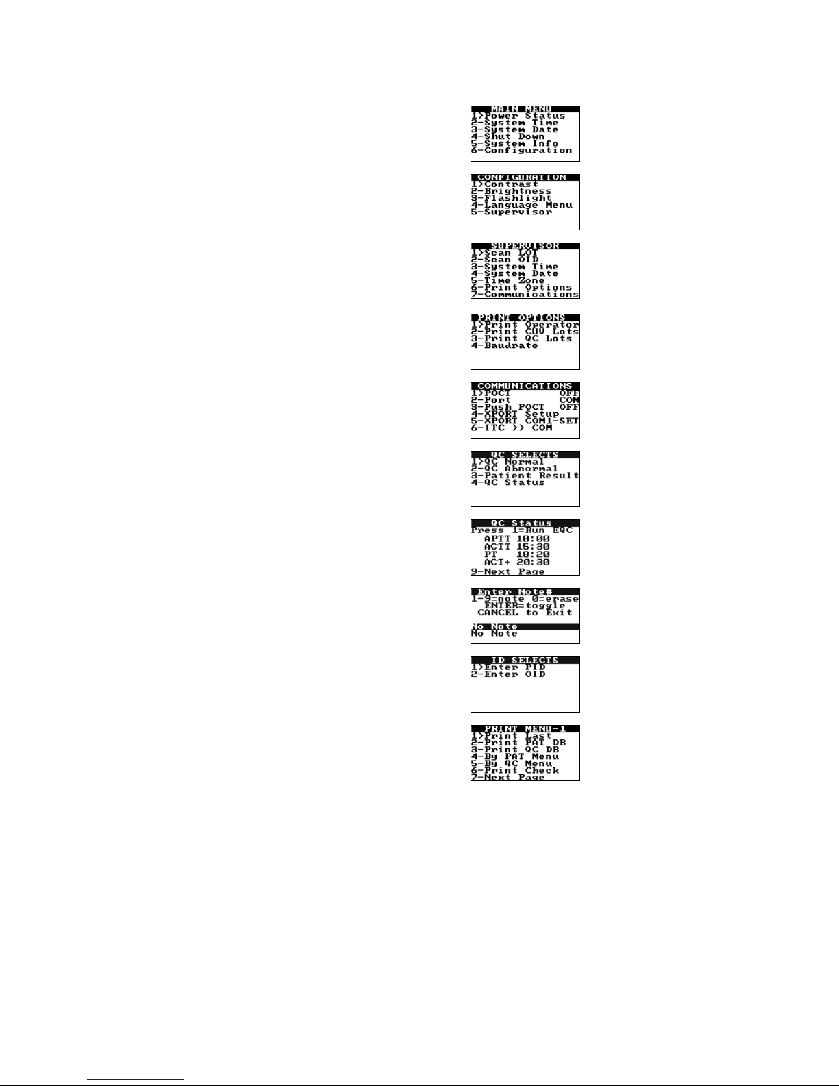
Menus
The action keys are used to display and activate various commands for operating and configuring the system.
The principal menus are shown below:
Menu
Commands
Access
Main Menu
Press the 0 (zero) key when no tests are
running and no other menu is active.
Configuration
Menu
Press the 6 key while the Main Menu is
displayed.
Supervisor
Menu
Press the 5 key while the Configuration
Menu is displayed, enter the supervisor
PIN at the prompt, then press and hold
the Enter key.
Print Options
Menu
Press the 6 key while the Supervisor
Menu is displayed.
Communications
Menu
Press the 7 key while the Supervisor
Menu is displayed.
QC Selects Menu
Press the QC key while a cuvette is
inserted in the instrument.
QC Status Menu
Press the QC key before a cuvette is
inserted in the instrument
(or, select 4 from the QC Selects menu.)
Notes Menu
Press the NOTE key after a cuvette is
inserted in the instrument.
ID Selects Menu
Press the ID key while a cuvette is
inserted in the instrument.
Print/Scan
Menu 1
Press the PRINT/SCAN key.
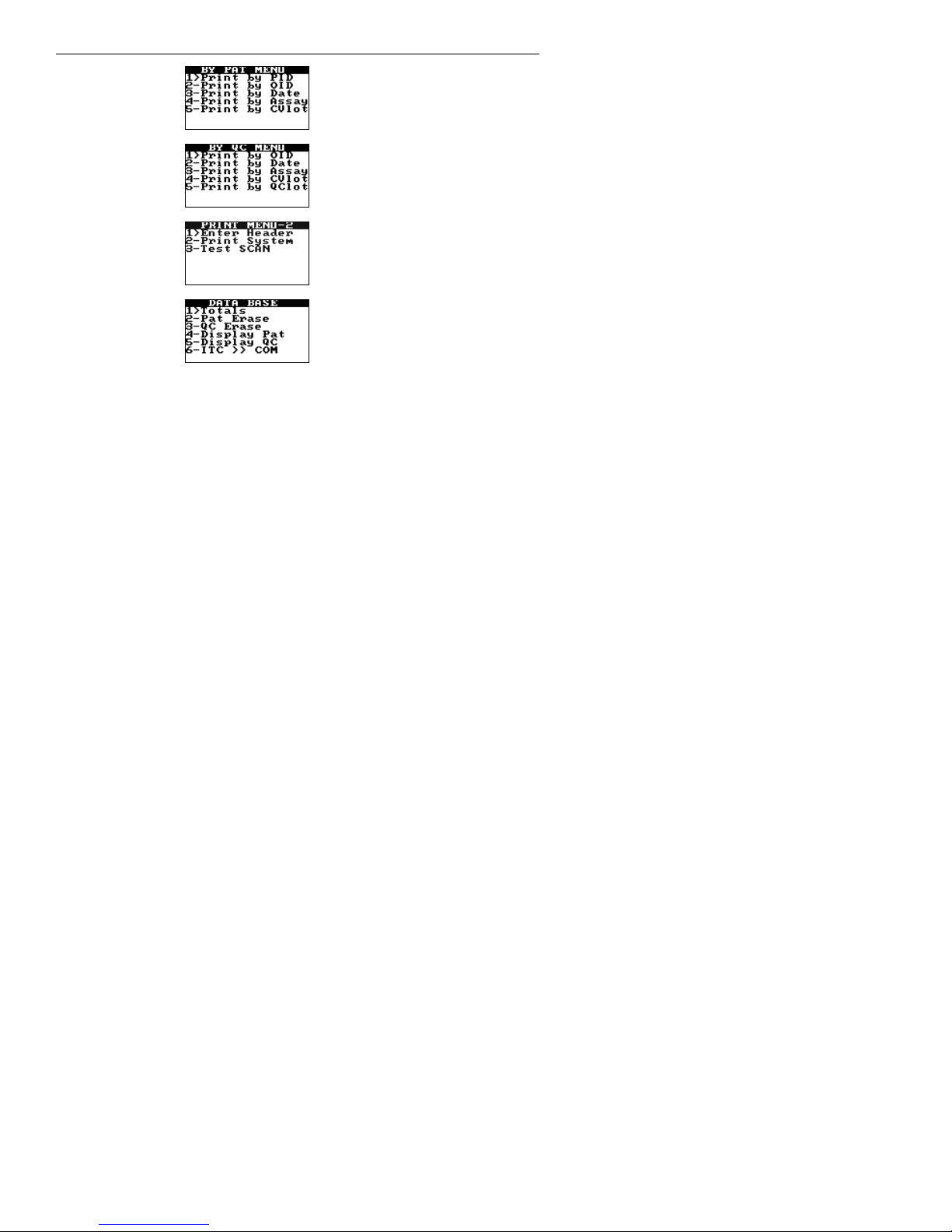
8
Menu
Commands
Access
Print by Patient
Menu
Press the 4 key while the Print Menu 1 is
displayed.
Print by QC
Menu
Press the 5 key while the Print Menu 1 is
displayed.
Print/Scan
Menu 2
Press the 7 key while Print Menu 1 is
displayed.
Database Menu
Press the DATABASE key.
Execute a command on a menu by pressing the action key for that command. For example, if the Main menu is
displayed, press the 4 key to shut down the system, or press the 5 key to display system information.
Note: The main menu cannot be accessed if a cuvette is in the test well. If a cuvette is used to turn on
the instrument, it must be removed to access the main menu.

9
Test Cuvettes
Tests are performed with single-use disposable HEMOCHRON Jr. test cuvettes. Each test cuvette contains a label,
a sample well, a test channel containing reagents, an enclosed waste reservoir, and one or more optical
detection windows.
The cuvette label is human- and instrument-readable. The current test is automatically read by the instrument
and displayed for confirmation when the operator inserts the cuvette into the test chamber. After the cuvette has
warmed, Add Sample and Press Start are displayed by the instrument, alerting the operator to place a drop of
blood in the sample well and begin the test by pressing the START key.
Note: Refer to the package insert accompanying the HEMOCHRON Jr. test cuvettes for storage and
handling instructions.
Features
The HEMOCHRON Signature Elite has a number of performance and convenience features. These are
summarized below:
• the system is portable for bedside use
• fresh whole blood or citrated whole blood can be used (assay dependent)
• only one drop of blood is required
• results are available in minutes
• results are displayed appropriately as whole blood, plasma equivalent, Celite equivalent seconds, or INR
• test type is automatically read from the cuvette
• barcode or manual entry of identification numbers, cuvette lot information, and quality control lot
information
• test results are automatically stamped with date and time
• results from 600 patient tests and 600 QC tests can be stored
• stored results can be printed and/or downloaded to a personal computer
• stored results can be printed by Patient ID
• instrument self checks are automatically performed
• internal Electronic Quality Control (EQC) is designed to check instrument operation at two levels
• Electronic Quality Control (EQC) levels selectable for 300 seconds or 500 seconds using HEMOCHRON
Configuration Manager software
• internal temperature verification is designed to check test chamber temperature
• the display is illuminated for viewing in low light
• the user is alerted when the battery is low
• an optional printer can be connected
• the system can be customized using a personal computer and HEMOCHRON Configuration Manager
software
• User Notes can be entered to add additional information to the test results
• Patient/QC test reports can be created using a personal computer and ITC data management software
programs
• POCT 1A compliant
• Operator certification lockout
• Cuvette expiration lockout
• QC expiration lockout
sample well
overflow area
test channel
label
detection
window

10
Instrument Lockouts
The instrument can be configured to allow use only by authorized operators and/or to allow use only if
specified QC has been performed. If one or more of these lockouts is enabled, processing of the lockout(s)
occurs before any other instrument functions.
Prewarming
If the lockout checks are passed, a cuvette is automatically prewarmed to 37 °C ±1.0 °C when it is placed in the
test chamber. The instrument will sound one short beep when pre-warming is complete.
Test Timeout
Incubation of a cuvette stops automatically if START is not pressed within five minutes after Add Sample and
Press Start are displayed.
Automatic Shutdown
The instrument will automatically shut down after being idle for five minutes if there is no cuvette inserted in
the test chamber and the instrument is running on the battery.
Note: Results that are greater than the time noted in the package insert for a test are beyond the
sensitivity range of the test. They should be repeated immediately and, if confirmed, reported as
greater than the maximum sensitivity range.
11
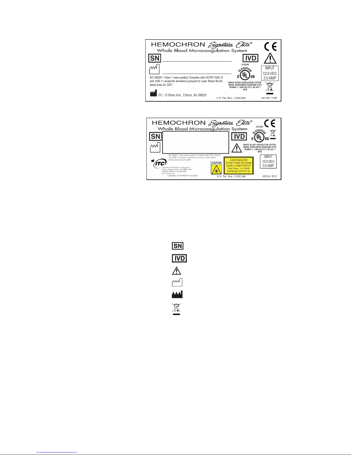
IMPORTANT LABELS AND SYMBOLS
Serial Number Label
A serial number label on the rear of the HEMOCHRON Signature Elite instrument alerts users to the following:
Class 1 Barcode Scanner
Class 2 Barcode Scanner
CAUTION: This manual provides safety instructions for instruments equipped with class 1 or class 2
barcode scanner lasers. Please refer to the back panel of the instrument to identify the class of laser
and follow appropriate instructions provided in this manual.
1. The barcode scanner contains an IEC 60825-1 class 1 or class 2 laser as indicated on the
labels (as shown above)
2. Serial Number of Device
3. For in vitro Diagnostic Use
4. Attention - Read accompanying documentation or instructions
5. Manufactured date
6. Manufacturer
7.
Medical Equipment per Annex 1A, Item 8 Directive 2002/96/EC For Electronic
Equipment Waste – Contact ITC Technical Support @ 1-800-631-5945

12
Other Symbols
Before using the HEMOCHRON Signature Elite system, it is essential that the contents of this Operator’s
Manual, any labels on the instrument or its packaging, and instructions accompanying HEMOCHRON Jr.
cuvettes are read and understood by the operator. These materials make reference to additional symbols that
are explained below:
Handle with care. Handle and open the container with care.
Expiration Date of Cuvettes
Lot Number of Cuvettes
Do Not Reuse Cuvettes – Single Use Only
Upper and Lower Temperature Limitations (For Storage or Use)
Consult Instructions for Use
Input Port for DC Power Cord from AC/DC Power Module - Polarity, VDC and
A Input.
RS232 Output Port for Data Transfer.
Ethernet Output Port for Data Transfer.
Laser Aperture Label. Alerts the user that a class 1 or class 2 laser Radiation is
emitted from the aperture. The label is located on the side of the instrument, next
to the aperture.

13
SPECIFICATIONS
Specifications for the HEMOCHRON Signature Elite Whole Blood Microcoagulation System are listed below.
Dimensions and Weight
Depth
9.4 cm (3.7 in)
Width
19 cm (7.5 in)
Height
5 cm (2.0 in)
Weight
0.53 kg (1.2 lbs)
Performance
Test Precision
≤ 10% C.V. for whole blood samples
Operation
Test Chamber
1
Timing Range
0 second to 1005 seconds
Incubation Temperature
37 °C ±1.0 °C
Incubation Warm-Up Time
30 seconds to 90 seconds
Full-Charge Operating Time
> 2 hours
Battery Life
500 recharges
Battery Type
Lithium Ion
Throughput (Full Charge)
49 test cycles (at 150 sec per test)
17 test cycles (> 500 sec per test)
Operating Environment
15 °C to 30 °C
AC/DC Power Module
Input Power
100 to 240 VAC, 50 to 60 Hz
Output Power
12.0 VDC, 3.5 Amps (42 Watts, 144 BTU/hr) minimum
Barcode Reader
Supported Barcode Formats
UPC/EAN, Code 128, Code 39, Trioptic Code 39,
Code 93, Interleaved 2 of 5, Discrete 2 of 5, Codabar,
and MSI Plessey
Laser Class
IEC 60825-1 class 1 or class 2 laser product complies with
21 CFR 1040.10 and 1040.11 except for deviations pursuant
to Laser Notice No. 50 dated June 24, 2007.
Laser Wavelength
Class 1: 630-670 nm
Class 2: 630-670 nm
Laser Power(peak)
Class 1: 0.7mW @peak
Class 2: 1.5 -1.9 mW @peak
Calibration
The Signature Elite instrument is calibrated at the manufacturing facility to test and verify all functions. The
instrument is also self-calibrating, as all instrument functions are continuously monitored and verified by the
instrument software when a test is performed. The instrument does not require additional calibration by the
user.
For Class 2 Laser Instruments:
CAUTION: CLASS 2 LASER RADIATION WHEN OPEN. DO NOT STARE INTO THE BEAM.
CAUTION: This manual provides safety instructions for instruments equipped with class 1 or class 2
barcode scanner lasers. Please refer to the back panel of the instrument to identify the class of laser
and follow appropriate instructions provided in this manual.

14
PREPARING THE INSTRUMENT
Unpacking and Inspection
Note: Inspect each component for damage when unpacking. If damage is observed, contact your shipper
or service representative immediately.
1. Remove any protective packaging that may be present around the instrument.
2. Examine the packaging material to be sure that the power supply, connecting cables or other
components have been removed. The materials that are provided are listed below.
Note: Do not discard the packaging material.
Materials Provided
Article
Quantity
HEMOCHRON Signature Elite Microcoagulation Instrument
1
PC Cable (ITC Part No. HJ7405; see Connecting a Computer or
Printer on page 25)
1
AC/DC Power Module (ITC Part No. HX1025)
1
Operator’s Manual
1
HEMOCHRON Configuration Manager CD V3.0 or higher
1
Note: An AC power cord is provided in the United States, Canada, and Japan only. For other
countries, the customer must obtain a power supply cord.
Materials Required, But Not Provided
Article
Quantity
HEMOCHRON Jr. Test Cuvettes
As Needed
HEMOCHRON Jr. Quality Control Products
As Needed
Optional Materials
Article
Quantity
HEMOCHRON Jr. PKIT (Printer Kit)
1
HEMOCHRON Jr. PCKIT (Personal Computer Interface Cable)
1
HEMOCHRON Jr. CBL-SIG (Serial Printer Interface Cable)
1
HEMOCHRON ReportMaker™ V6.0 or higher CD (Data Management
Software)
1
idms V7.2 or higher (Integrated Data Management System)
1
Charging the Battery
The battery of the system should be charged before the system is used.
1. Plug the AC/DC Power Module into an electrical service outlet.
2. Connect the AC/DC Power Module cord to the power connector on the side of the instrument. The
charge indicator on the instrument keypad will illuminate.
3. Allow the battery to charge for at least eight hours.
Note: The AC/DC Power Module can remain connected all the time.
4. To ensure adequate charge, leave the instrument connected to the charger for a minimum of eight
hours. This eliminates the risk of the instrument powering down during a test.
15
Battery Warnings
The message CHARGE BATTERY is displayed intermittently when the remaining battery power is insufficient to
ensure test completion. The message BATTERY FAULT is displayed when the battery is completely discharged
and cannot be used to run additional tests. The AC/DC Power Module must be used for additional tests until the
battery is recharged.
If either the battery voltage or the AC/DC Power Module voltage is too high, the instrument beeps continuously
and displays the message DISCONNECT AC ADAPTER IMMEDIATELY. The AC/DC Power Module must be
disconnected to shut down the instrument in this condition.
Checking the Battery
1. Press and hold START to turn on the instrument.
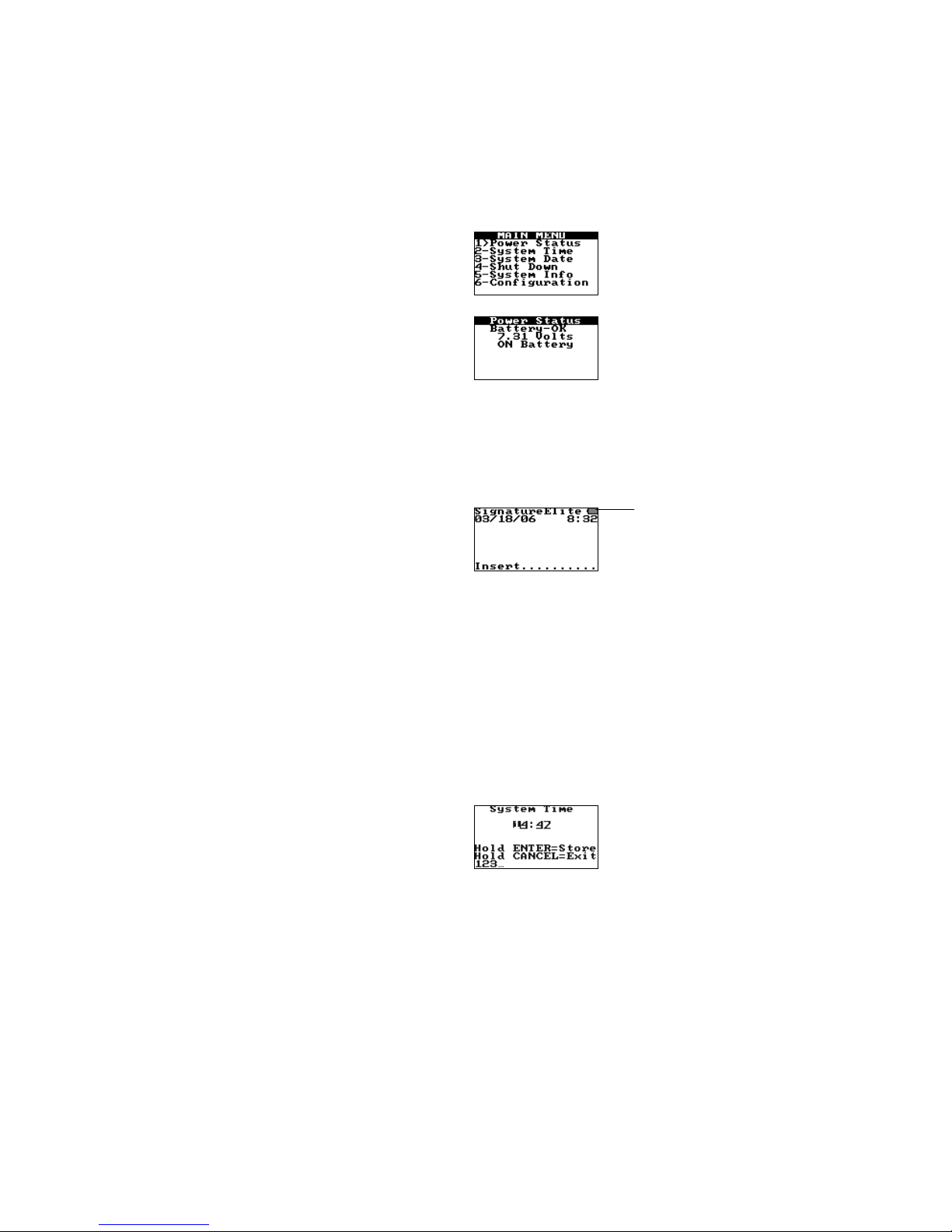
2. Press 0 (zero) to display the main menu:
3. Press 1. The battery status is displayed:
Note: Battery status is displayed as OK, LOW, or BAD.
4. Press CANCEL twice to return to normal operation.
Battery Charge Indicators
A battery charge LED on the front panel (page 5) is illuminated whenever the battery is being charged. The LED
flashes when the remaining battery power is low. A battery charge status indicator is also displayed in the
upper right corner of the screen when a system disconnected from the AC/DC Power Module is ready to run a
test.
Setting the System Time and Date
The time and date a test is run is saved with the test results. The system time and date can be reset by the
operator unless the system is in a lockout condition or the time and date are permanently locked (see the
Configuration Manager section).
Note: The date and time can also be set from the Supervisor menu (page 18) or from
HEMOCHRON Configuration Manager (page 72). If the unit has been off for an extended period of
time or the battery is very weak, the operator will be prompted to enter or verify that the time and
date are correct.
To Set the System Time:
1. Press and hold START to turn on the instrument.
2. Press 0 (zero) to display the main menu.
3. Press 2 to display the time:
battery charge
status indicator
16
4. Enter the new time using the numeric keys.
Note: Use the 24-hour format (i.e., enter 15:30 for 3:30 pm). The leading zero is required for
single digit times (i.e., enter 06:30 for 6:30 am).
5. Press and hold down ENTER. Stored is displayed and the entry is saved.
6. Press CANCEL to return to normal operation.
To Set the System Date:
1. Press and hold START to turn on the instrument.
2. Press 0 (zero) to display the main menu.
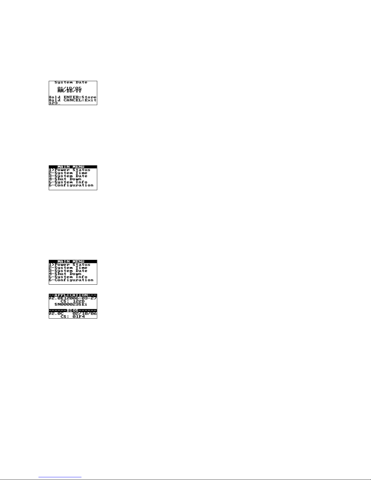
3. Press 3 to display the date:
4. Type the new date using the numeric keys.
Note: Use the US (i.e., MM/DD/YY) or the IVDD (i.e., YY-MM-DD) date format. The leading zero
is required for single digit dates (i.e., enter 06/01/06 for June 1, 2006).
5. Press and hold down ENTER. Stored is displayed and the entry is saved.
6. Press CANCEL to return to normal operation.
Instrument Shutdown
1. Press 0 (zero) to display the main menu:
2. Press 4. The instrument is shut down.
Note: The instrument can also be shut down by pressing and holding down the START key for
four seconds. The instrument will automatically shut down after being idle for five minutes if
there is no cuvette inserted in the test chamber and the instrument is running on the battery.
Displaying System Information
The instrument software version, instrument serial number, and other system software information for the
HEMOCHRON Signature Elite instrument can be displayed.
1. Press and hold START to turn on the instrument.
2. Press 0 (zero) to display the main menu:
3. Press 5 to display the system information:
(example only)
Note: The Main Menu will again be displayed after several seconds, or press CANCEL to return
to normal operation.
17
Configuring Display Brightness, Contrast, and Illumination
The brightness and contrast of the display can be adjusted and the length of time that the display remains
illuminated after a test is completed or a key is pressed can be set.
1. Press and hold START to turn on the instrument.
2. Press 0 (zero) to display the main menu.
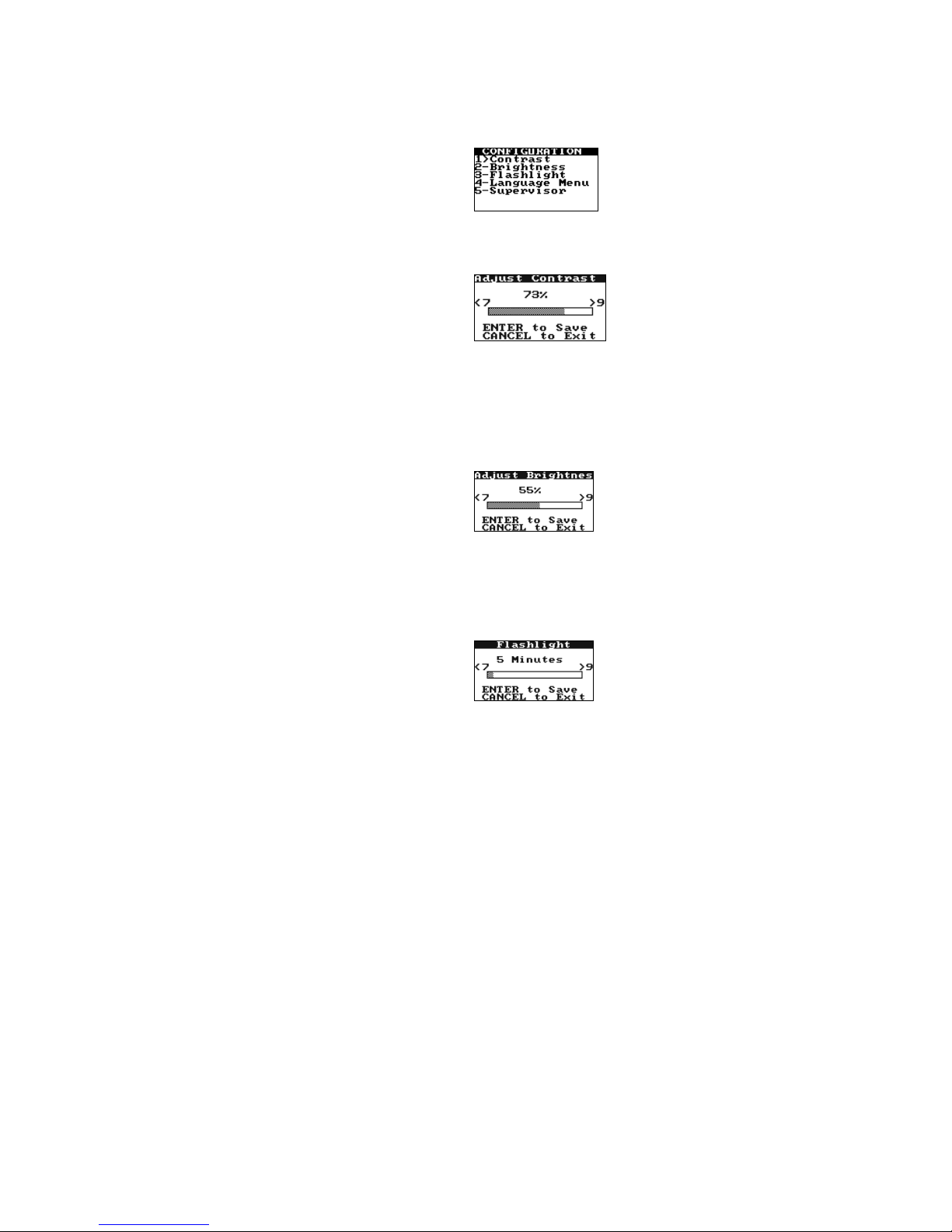
3. Press 6 for the Configuration menu:
To Adjust the Display Contrast:
Display contrast can be set so characters are darker (more contrast) or lighter (less contrast).
1. Press 1 to display the Contrast menu:
2. Press 7 to decrease the contrast. Press 9 to increase the contrast.
Note: Pressing and holding a key for more than one second will cause it to auto-repeat.
3. Press ENTER to save the new setting.
To Adjust the Display Brightness:
Display brightness can be set so the display background is darker or lighter.
1. Press 2 to display the Brightness menu:
2. Press 7 to decrease the brightness. Press 9 to increase the brightness.
Note: Pressing and holding a key for more than one second will cause it to auto-repeat.
3. Press ENTER to save the new setting.
To Adjust the Length of Time the Display Remains Illuminated:
1. Press 3 to display the Flashlight menu:
2. Press 7 to decrease the length of time the display remains illuminated. Press 9 to increase the time.
Note: Pressing and holding a key for more than one second will cause it to auto-repeat.
Note: The factory default time for display illumination is five minutes. The maximum
illumination time is 100 minutes. To disable display illumination, set the time to zero (0).
3. Press ENTER to save the new setting.
18
Displaying Available Languages
English is the only language that is available in HEMOCHRON Signature Elite software. Additional languages
will be available in future software versions.
To Display the Menu of Available Languages:
1. Press and hold START to turn on the instrument.
2. Press 0 (zero) to display the main menu.
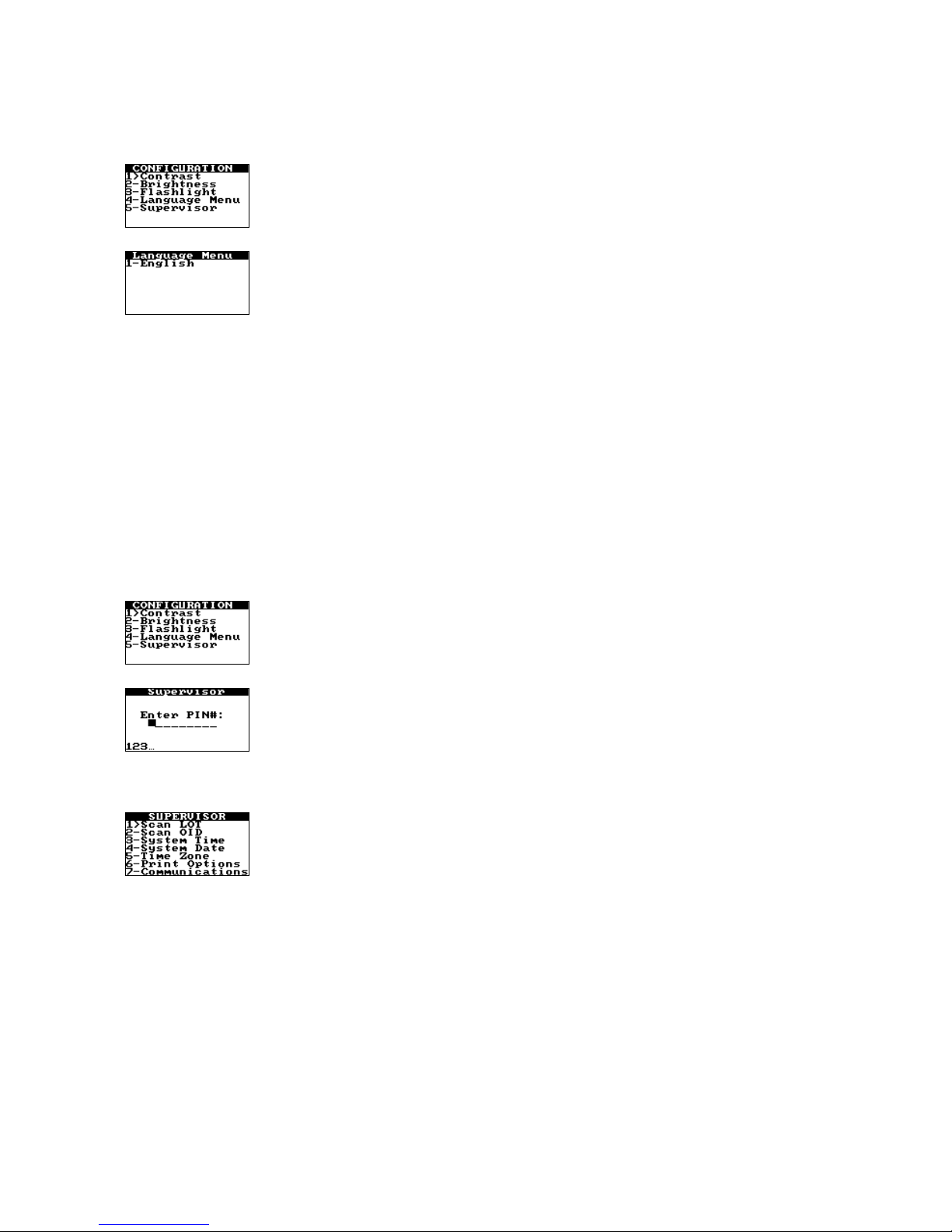
3. Press 6 for the Configuration menu:
4. Press 4 to display the menu of available languages:
5. Press the numeral key that corresponds to the language to be used.
6. Press ENTER to save the new setting.
Supervisor Functions
The Supervisor menu allows additional actions to be carried out by the laboratory supervisor:
• Scan cuvette or quality control material barcodes to upload the lot number, expiration date, and
expected range (for control materials) to HEMOCHRON Configuration Manager
• Scan Operator IDs for uploading to HEMOCHRON Configuration Manager
• Set the instrument date and time (this can also be done from the main menu)
• Print listings of cuvette lot numbers, quality control lot numbers, or Operator IDs
• Set the instrument baud rate
• Enter communication parameters
To Access the Supervisor Functions:
1. Press and hold START to turn on the instrument.
2. Press 0 (zero) to display the main menu.
3. Press 6 for the Configuration menu:
4. Press 5. A prompt is displayed to enter the Supervisor PIN:
Note: The Supervisor PIN is set using HEMOCHRON Configuration Manager (see page 55). If an
instrument does not yet have a Supervisor PIN, press and hold the ENTER key at the prompt.
5. Enter the Supervisor PIN, then press and hold the ENTER key. The Supervisor menu is displayed:

19
Scanning Lot Information for Cuvettes or Quality Control Materials
1. On the Supervisor menu, press 1 to display the Scan Lot screen:
2. Hold the instrument over the barcode on the cuvette wrapper or QC package:
Note: Position the scanner port of the instrument approximately four inches from the
barcode (see page 5).
3. Press PRINT/SCAN to scan the barcode label. The scanned lot number and a Stored confirmation
message are displayed, and the entry is saved.
Note: Additional lots can be scanned by repeating Steps 2 and 3.
4. Press CANCEL to exit.
Scanning Operator IDs
1. On the Supervisor menu, press 2 to display the Scan OID screen:
2. Position the scanner port of the instrument approximately four inches from the barcode
(see page 5).
3. Press PRINT/SCAN to scan the barcode. The scanned Operator ID and a Stored confirmation
message are displayed, and the entry is saved.
Note: Additional Operator IDs can be scanned by repeating Steps 2 and 3.
4. Press CANCEL to exit.
Setting the System Time or System Date
For convenience, the Supervisor menu includes the same commands that are on the main menu for
changing the system time and system date.
1. On the Supervisor menu, press 3 to set the system time.
2. On the Supervisor menu, press 4 to set the system date.
Note: Procedures for setting the system time and system date are described on page 15.
(cuvette wrapper)
barcode
(QC package)
barcode
20
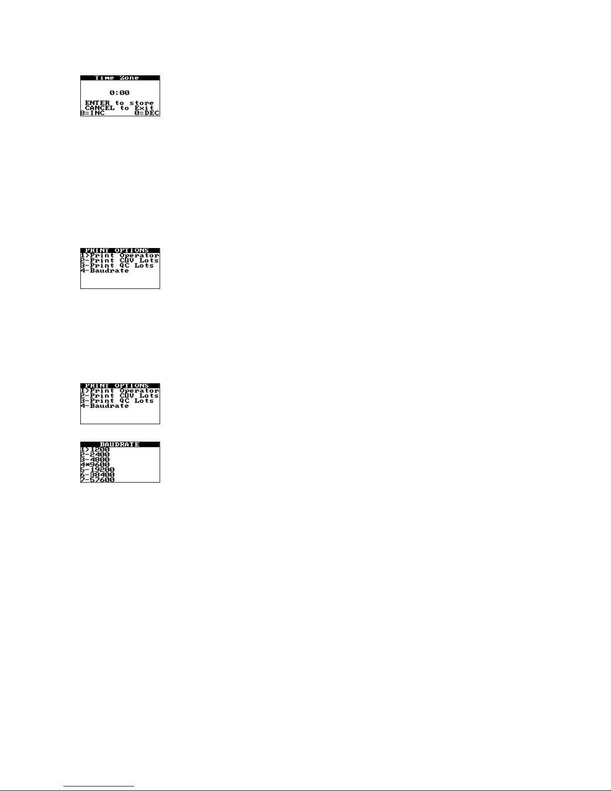
Specifying the Time Zone
The time zone setting is used to compare the instrument time to Greenwich Mean Time (GMT). This allows
the instrument to communicate with other devices in accordance with CLSI Standard POCT-1A.
1. On the Supervisor menu, press 5 to display the Time Zone screen:
2. Enter the difference (in hours and minutes) between the local time zone and GMT. For example, if
the local time is 2:00 pm and GMT is 7:00 pm, enter –5.00.
Note: Press the 8 key to enter positive (+) time differences in 15-minute increments. Press the 0
key to enter negative (-) time differences in 15-minute increments.
3. Press ENTER to store the time zone.
4. Press CANCEL to exit.
Specifying Print Options
Listings of cuvette lot numbers, quality control lot numbers, or Operator IDs can be printed at an external
printer (see page 25 for instructions to connect the printer).
1. On the Supervisor menu, press 6 to display the Print Options menu:
2. Press 1 to print a listing of Operator IDs.
3. Press 2 to print a listing of cuvette lot numbers.
4. Press 3 to print a listing of quality control material numbers.
Specifying the Baud Rate
Listings of cuvette lot numbers, quality control lot numbers, or Operator IDs can be printed at an external
printer (see page 25 for instruction to connect the printer).
1. On the Supervisor menu, press 6 to display the Print Options menu:
2. Press 4 to display the Baud Rate screen.
3. Press the numeral key that corresponds to the baud rate to be selected.
Note: The baud rate that is currently specified is designated by an asterisk (*).
4. Press CANCEL to exit.

21
Specifying the Communication Protocol
The instrument can communicate with a personal computer (using the COM port) or a network (using the
Ethernet port). One of two communication protocols can be selected:
• An ITC proprietary communication protocol that allows records to be transferred from the
instrument and allows the instrument to be configured using ITC software such as HEMOCHRON
Configuration Manager. This protocol is supported over COM or NET.
• A communication protocol that meets CLSI POCT-1A standards. This protocol allows the instrument
to communicate with any software or device that is compliant with POCT-1A. This protocol is
supported over NET only. If Port COM is selected, the following message is displayed:
Note: If the CLSI POCT-1A compliant communication protocol is used, communication must be
initiated from the instrument. If the ITC proprietary communication protocol is used,
communication must be initiated from either the personal computer or the network.
1. From the Supervisor menu, press 7 to display the Communications menu:
2. Press 1 to select the desired communication protocol. (Display OFF to use the ITC proprietary
communication protocol, or display ON to use the CLSI POCT-1A compliant communication
protocol.)
Note: If Port is set to COM when attempting to set POCT ON, the setting will not be allowed and
the message UNSUPPORTED POCT >> COM will be displayed. Specifying POCT connectivity acts as
a toggle. If CLSI POCT-1A connectivity standards are already specified (POCT ON is displayed), this
can be cancelled by pressing 1 again to display POCT OFF.
Specifying the Communication Port
1. From the Supervisor menu, press 7 to display the Communications menu:
2. Press 2 to select the desired port. (Display COM to specify use of the COM port, or display NET to
specify use of the Ethernet port.)
Note: If POCT is set to ON when attempting to set Port COM, the setting will not be allowed and
the message UNSUPPORTED POCT >> COM will be displayed. Specifying the port acts as a toggle. If
use of the Ethernet port is already specified (Port NET is displayed), this can be cancelled by
pressing 2 again to display Port COM.

22
Specifying Continuous POCT-1A Communication
Note: Communication is initiated from the instrument only when the CLSI POCT-1A compliant
communication protocol is used. If the ITC proprietary communication protocol is used,
communication is initiated from a personal computer or network.
1. From the Supervisor menu, press 7 to display the Communications menu:
2. Press 3 to select the desired communication option when the CLSI POCT-1A compliant
communication protocol is used. (Display OFF to initiate communication only if requested, or
display ON to initiate continuous communication whenever the instrument is started.)
Note: Specifying the communication option acts as a toggle. If initiation of communication upon
startup is already specified (Push POCT ON is displayed), this can be cancelled by pressing 3 again
to display Push POCT OFF.
Entering Network Communication Parameters
Some or all of the following parameters may need to be entered in order for the instrument to
communicate over a network:
• IP Address
• Gateway
• NetMask
• Remote IP
• Remote Port
Note: Consult with the network administrator for your facility to determine which parameters
must be entered and what those settings should be.
1. From the Supervisor menu, press 7 to display the Communications menu:
2. (If the CLSI POCT-1A compliant communication protocol is currently selected): Press 1 to toggle the
communication protocol to the ITC proprietary communication protocol:
Note: The CLSI POCT-1A compliant communication protocol must be OFF when running XPORT
Setup.
3. Press 4 to start the XPORT Setup module. The message XPORT Setup Please Wait is displayed,
followed by the first page of the XPORT Setup module:
Note: If the message XPORT Setup NOT RESPONDING! is displayed, contact ITC Technical Support
at (800) 631-5945 or (732) 548-5700, or by e-mail at techsupport@itcmed.com.

23
4. Press 0 to display the next page (for entering IP Address and Gateway settings):
5. Press 1 to display the screen for entry of the IP Address:
Enter the IP Address using the numeral keys:
Note: Press Enter to move to the next field without entering a numeral. Press Cancel to move to
the previous field.
6. After the IP Address has been entered, press and hold ENTER. The message Parameter String
Stored is displayed, followed by the screen for entering IP Address and Gateway settings:
Important: The parameter string is temporarily stored. Even though the new parameter is
displayed on the screen, it is not saved until Enter is pressed to exit XPORT Setup (Step 13).
Note: A range of IP addresses (from 169.254.0.1 to 169.254.255.1) has been reserved for Auto-IP
enabled devices. This range of Auto IP addresses should not to be used over the Internet.
Auto-IP can be disabled by setting the device’s IP address to 000.000.001.000. This setting enables
DHCP but disables Auto-IP.
7. Press 2 to display the screen for entry of the Gateway. Enter the Gateway in the same manner as for
the IP Address, then press and hold ENTER to again display the screen for entering IP Address and
Gateway settings.
8. Press 0 to display the next page (for entering NetMask and Remote IP settings) of the XPORT Setup
module:
9. Press 3 to display the screen for entry of the NetMask. Enter the NetMask in the same manner as for
the IP Address, then press and hold ENTER to again display the screen for entering NetMask and
Remote IP settings.
10. Press 4 to display the screen for entry of the Remote IP. Enter the Remote IP in the same manner as
for the IP Address, then press and hold ENTER to again display the screen for entering NetMask and
Remote IP settings.

24
11. Press 0 to display the next page (for entering the Remote Port setting) of the XPORT Setup module:
12. Press 5 to display the screen for entry of the Remote Port. Enter the Remote Port in the same manner
as for the IP Address, then press and hold ENTER to again display the screen for entering the Remote
Port setting.
13. Press ENTER while any page of the XPORT Setup module is displayed to save the new parameters.
The message Updating XPORT is displayed, followed by the Communications menu (see Step 1).
Important: Parameters are temporarily stored until the Enter key is pressed while any page of
the XPORT Setup module is displayed. If the Cancel key is pressed while any page of the XPORT
Setup module is displayed, the message Cancel without updating XPORT? is displayed for
confirmation by the operator.
Note: The parameters can be printed to a device connected to the COM port by pressing the
PRINT/SCAN key.
Configuring Network Communication Parameters Using a Personal Computer
An experienced network administrator can communicate with the XPORT Setup module and enter
communication parameters using a personal computer connected to the COM port.
1. From the Supervisor menu, press 7 to display the Communications menu:
2. (If the CLSI POCT-1A compliant communication protocol is currently ON): Press 1 to toggle ON to
OFF for the ITC proprietary communication protocol:
Note: The CLSI POCT-1A compliant communication protocol must be OFF when running XPORT
Setup.
3. Press 5 to start the XPORT COM-1 Setup module. The message XPORT Setup Please Wait is
displayed, followed by the message XPORT COM1-SET.
The XPORT module can now communicate with the personal computer through the COM port, using
terminal emulator software such as Microsoft Windows Hyperterminal.
Note: Description of XPORT Setup menus and commands using terminal emulator software is
beyond the scope of this Operator’s Manual. If needed, contact ITC Technical Support for assistance
at (800) 631-5945 or (732) 548-5700, or by e-mail at techsupport@itcmed.com.
4. Upon completing the communication session, press Cancel to exit the session and display the
Communications menu again.

25
Connecting a Computer or Printer
An IBM-compatible laboratory computer or a serial printer (Seiko DPU-414 is recommended) can be used with
the system. The connector port for these devices is located at the side of the instrument.
To Connect to a Printer:
1. Obtain a printer interface cable.
Note: The printer interface cable is included with the optional HEMOCHRON Jr. PKIT (Printer
Kit) only. A separate CBL-SIG (Serial Printer Interface Cable) can be obtained from ITC, or a
cable can be prepared as outlined below. If a printer is connected, the serial printer
communication parameters must be set to 9600 baud with no parity, 8 data bits and 1 stopbit
using XON/XOFF 3-wire software protocol. For additional information on printer configuration,
contact ITC Technical Support at (800) 631-5945 or (732) 548-5700, or by e-mail at
techsupport@itcmed.com.
2. Connect one end of the cable to the printer connector port on the side of the instrument.
3. Connect the other end of the printer cable to the printer.
To Connect to a Personal Computer:
1. Obtain a computer interface cable.
Note: The computer interface cable is included with the instrument. A replacement PCKIT
(Personal Computer Interface Cable) can be obtained from ITC, or a cable can be prepared as
outlined below. Contact ITC Technical Support for instructions on setting up the personal
computer.
2. Connect one end of the cable to the computer connector port on the side of the instrument.
3. Connect the other end of the cable to an unused serial communication port on the computer.
To Connect to a Network:
1. Obtain a network interface cable.
2. Connect one end of the cable to the Ethernet port on the side of the instrument.
3. Connect the other end of the cable to a network connection port.
Preparing a Printer or Computer Interface Cable
Cabling and connectors can be purchased locally at an electronics store. Use an 8-wire RJ45 to RJ45 modular
straight through connecting cable (no longer than 25 feet) plus an RJ45 to DB9 adapter. Numbering of the pins
on the RJ45 connectors is shown below:
Connector Port for
AC/DC Power Module
Connector Port for
Computer or Printer
Ethernet Port
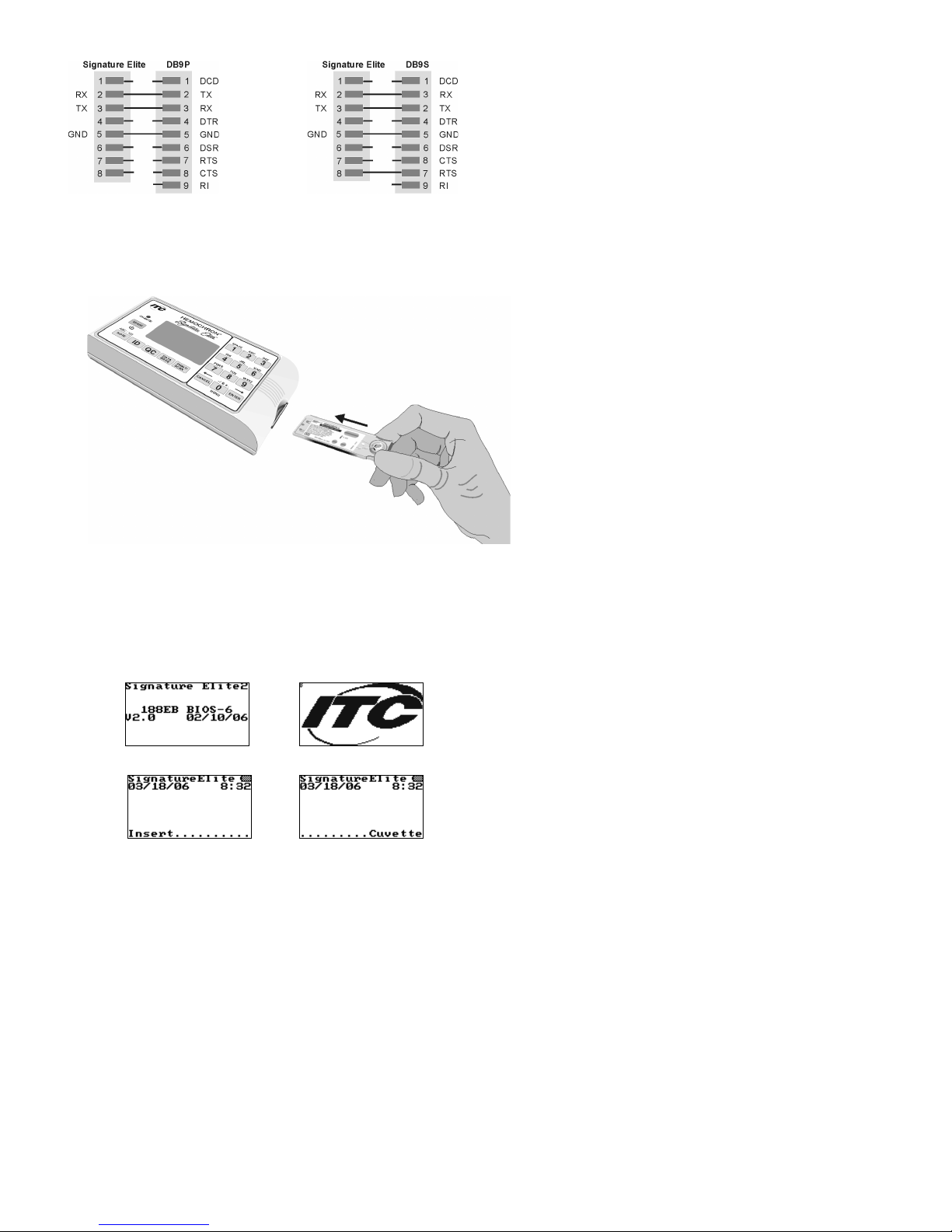
26
The cable configurations used for connecting a serial printer or a computer are shown below:
Connecting the instrument to the Seiko
DPU-414 printer with a DB9S connector
Connecting the instrument to any personal
computer with a DB9P connector
STARTING THE INSTRUMENT
Start the instrument by pressing and holding down the START key or by inserting a cuvette:
Note: Allow cuvettes to reach room temperature (15 to 30 °C) before opening the pouch. This may
take up to 60 minutes. Consult the cuvette package insert for additional information concerning
cuvette storage and handling.
Note: Insert the cuvette with the label facing up. Push the cuvette all the way in until it stops.
Starting the Instrument by Pressing the START Key
1. When the START key is pressed, the following screens are briefly displayed:
and
2. The instrument then prompts the user that the instrument is ready to accept a cuvette:
and
 Loading...