

Page 1
JUMP TO:
Trouble Shooting
Warnings
Basic Diagnostics
Repairs
Maintenance
Wiring Diagram
LPEFI
General Diagnostic Manual
2012 Isuzu NPR Trucks with 6.0 Liter Engine
Mono-Rail System
(Trinity Industries Tank Design)
October, 2012
Manual # M4-121-Isuzu
Bi-Phase Technologies, LLC
Eagan, Minnesota, U.S.A.
Page 2

This manual is for general diagnosis that applies to any LPEFI
system installed on any
vehicle. Where there is a difference in components or installation, it will be identified by
specific vehicle. The theory and diagnostics for the system are the same for any vehicle
that the system might be installed on. However, the system is calibrated to a specific
vehicle and some components, specifically injectors, cannot be interchanged.
In this manual you will find different approaches to diagnostics and troubleshooting. We
will reference specific OEM repair manuals where a technician may need to obtain the
OEM manual to complete the diagnostics. In many cases, the propane injection system
may not be the fault and further investigation of the engine control system may be
required. Remember the basics when troubleshooting. To prevent the replacement of
good components it is necessary to have a general knowledge of both the LPEFI
system
and the vehicle.
“Read all instructions before use to avoid injury”
Anyone who performs repairs to the LPEFI
system must be trained and
certified. This is a propane system and anyone who performs repairs must
have knowledge of Liquefied Petroleum Gases and understand safe
handling and characteristics of such. Some states may require a license to
work on propane vehicles. Consult your state or local authorities or your
state propane gas association. Bi-Phase Technologies is not responsible
for your oversight to comply with federal, state or local laws regulating
the installation or repair of propane gas systems.
The LPEFI
system is a sequential multi-port fuel injection system that injects propane in
a liquid state to the engine. It works the same way as a modern sequential multi-port
gasoline fuel injection system and can be diagnosed with the same diagnostic scanners
used for gasoline vehicles.
The LPEFI system is covered by U.S. and International patents. The LPEFI
system is
also certified to the United States E.P.A. standards.
The information in this manual is believed to be accurate as of its date of publication but
it is subject to change. Up-to-date information and changes, if any, can be requested
from Bi-Phase Technologies.
In the event of any safety-related changes, Bi-Phase Technologies will notify all
customers who returned the warranty registration card for the affected vehicles.
1
Page 3

2
TABLE OF CONTENTS
PropaneSafetyWarnings...................................................................................................................4‐5
FactsaboutPropane&PropanePoweredVehicles................................................................................6
ApproximatePropertiesofLPGases......................................................................................................7
Theory&Operation...........................................................................................................................8‐9
BasicDiagnostics............................................................................................................................10‐15
Checking&ReleasingFuelPressure..........................................................................................11‐12,21‐25
CheckingFuelLines.............................................................................................................................13‐14
CheckingFuelInjectors.......................................................................................................................14‐15
Electron
3SwitchBoxAmperageTestSpecifications..........................................................................................21
PressureTestingtheLPEFI
LPEFI
TroubleshootingbySymptom.........................................................................................................26‐33
icEn
gineManagement......................................................................................................16‐20
®
system(FlowChart)..............................................................................22‐24
®
PurgeLogic................................................................................................................................25
RepairProcedures..........................................................................................................................34‐53
Injectors..............................................................................................................................................35‐37
LPDM...................................................................................................................................................38‐44
FuelPump.............................................................................................................................................39
FuelLines...................................................................................................................................................45
TankControlBox(PurgeBox)...................................................................................................................46
Purgingthetank..................................................................................................................................47‐49
Drain/Evacuatingthetank..................................................................................................................50‐53
Mainte
SendingUnitValues............................................................................................................................55
WiringDiagram…………………………………………………………………………………………………………………………………60
Tank&HoseConfigurations...........................................................................................................61‐62
ServiceTools.......................................................................................................................................63
nance...............................................................................................................................
...54‐59
Page 4

Bi‐PhaseTechnologies,LLC
Page left blank for notes
3
Page 5
Bi-Phase Technologies
LPEFI Propane Safety
4
This is a safety alert symbol. It is used throughout this manual to alert you to
potential hazards. Whenever you see this symbol, you should read and obey the safety
warnings that follow. Failure to obey these warnings could result in serious personal
injury or property damage.
Warning: Never loosen fittings or vent any propane. Escaping
propane can cause frostbite and severe freeze burns. Wear
insulated PVC rubber gloves resistant to propane. Goggles
for protection against accidental release of pressurized
products and thermal protective clothing when handling
refrigerated liquids.
Propane is stored as a liquid. When you release liquid propane, it tries to evaporate as
quickly as it can, by absorbing heat from its surroundings. Everything it touches gets
chilled to -44 degrees F (-42 degrees C). If liquid propane sprays on your skin, it will
freeze it. Anyone who works with liquid propane must wear PVC insulated rubber
gloves.
Danger: Do not remove any valves, bulkheads, or fittings from a
tank unless the tank has been drained completely. The
pressure inside a propane tank can push a loosened
bulkhead or valve out with enough force to cause injury or
death.
Propane is stored under pressure. When you remove a valve or bulkhead from the tank, all
of the pressure is released at once in a violent rush. Always drain the tank before you work
on it. Failure to do this will result in damage to the tank or valves and can result in severe
injury or death. You should drain the tank by the fuel transfer method and/or by using a
flare stack in an approved safe manner. Your propane supplier can help you with this.
_______________________________________________________________________
Page 6

Bi-Phase Technologies
LPEFI Propane Safety
_______________________________________________________________________
Warning: Keep all sources of ignition away from propane vehicles
while the fuel system is being serviced. Even if the tank
and fuel lines are empty, there may still be flammable
vapors near the vehicle.
Do not allow smoking, sparks, flames, recent or running vehicles or other sources of
ignition when fueling, servicing and vented propane. Failure to do this could result in
fire or explosion, causing severe property damage, injury or death.
_______________________________________________________________________
Warning: Do not disconnect any propane hoses unless they have been
properly drained completely.
Propane in the hoses is kept under pressure, even when the engine is off. When you
disconnect a hose; the internal pressure is released all at once. Always drain the fuel
lines before you disconnect them. Failure to do this can result in damage to the hose
fitting and possible injury. See repair procedures in this manual for instructions.
________________________________________________________________ _______
5
Danger: Do not vent or release propane indoors or near sewers, pits
or low lying areas. Propane can accumulate in low spots,
creating a fire hazard. Propane can also displace oxygen,
creating a suffocation hazard.
Propane is heavier than air. It can fill low, sheltered areas with flammable vapors. If
these vapors are ignited, they can create a fire or explosion, causing severe property
damage, injury or death. Never release propane near sewers, pits or indoors.
_______________________________________________________________________
Page 7

Bi-Phase Technologies
LPEFI Facts about Propane & Propane Powered Vehicles
Propane gas is the most widely used alternative fuel, with nearly 4 million vehicles
worldwide running on propane. More than 350,000 vehicles run on propane in the U.S.
according to the U.S. Department of Energy’s Alternative Fuels Data Center.
Propane powered vehicles offer the best combination of durability, performance and
driving range.
The first propane powered vehicle ran in 1913.
Bi-Phase Technologies’ LPEFI
(Liquid Propane Electronic Fuel Injection) system has
surpassed other technologies today by introducing liquid fuel injection. This technology
improves power, efficiency and operating characteristics. For more information, call for
our General Information and Training Manual.
Safety comes first is a motto you should always live by. Without knowledge of a
product, it is hard to follow this motto. In our manuals we try to stress the need for
knowledge and provide warning signs to alert you.
It is your responsibility to know the law. National Fire Protection Association (NFPA)
has manuals to help you understand safe handling of many products. We recommend
that you obtain and read their NFPA #58, Standard for the Storage and Handling of
Liquefied Petroleum Gases.
A number of training programs and efforts have been implemented throughout the
country. The National Propane Gas Association has developed a Certified Employee
Training Program (CETP), which provides service personnel with a complete technical
training curriculum. We encourage you to contact your state propane gas association or
the National Propane Gas Association for more information on how you can benefit from
such programs. Visit www.propanesafety.com or www.npga.org for more information.
6
Page 8

Bi-Phase Technologies
LPEFI Approximate Properties of LP Gases
(Commercial Propane)
C
3H8
Specific gravity of liquid (water = 1) at 60 degrees F. 0.504
Initial boiling point at 14.7 psia, in degrees F. - 44.0
Weight in pounds per gallon of liquid at 60 degrees F. 4.24
Cubic ft. of vapor per gallon at 60 degrees F. 36.38
Cubic ft. of vapor per pound at 60 degrees F. 8.66
Specific gravity of vapor (air = 1) at 60 degrees F. 1.50
Ignition temperature in air, in degrees F. 920 to 1120
Maximum flame temperature in air, in degrees F. 3,595
Limits of flammability in air
Percent of vapor in air/gas mixture
Lower 2.15
Upper 9.60
Air/Fuel ratio by volume 15.6:1
Air/Fuel ratio by weight 24:1
Octane number as it relates to gasoline 98 to 102
Heating values
BTU per cubic foot 2,488
BTU per pound 21,548
BTU per gallon 91,500
Chemical formula C
Vapor pressure in psig
70 degrees F 127
100 degrees F 196
105 degrees F 210
3H8
7
Page 9

L
I
y
Bi-Phase Technologies
PEF
Theor
& Operation
Introduction
This article covers basic description and operation of the LPEFI system. Read this information before
diagnosing vehicles or systems with which you are not completely familiar.
The LPEFI System
The LPEFI
system is a direct replacement propane fuel injection system. It replaces the gasoline fuel
injection system and works the same as a gasoline fuel injection system with the exception it injects
propane, in a liquid state, into the intake port. The gasoline system electronic engine management stays the
same and controls the LPEFI
system just as it did the gasoline injection system. Onboard diagnostics
remain unchanged so the same scan tool and diagnostic approach remains equal to a gasoline system. The
only change in electronic engine management is the fuel enrichment strategy on start up. Gasoline needs a
very rich fuel mixture to start the engine and differs greatly based on outside ambient temperatures. With
propane this fuel enrichment requirement is much less, thus reducing the level of start up emissions
compared with gasoline. The LPEFI
system accomplishes this start up fuel enrichment strategy by
recalibrating the PCM for propane fuel enrichment.
The LPEFI
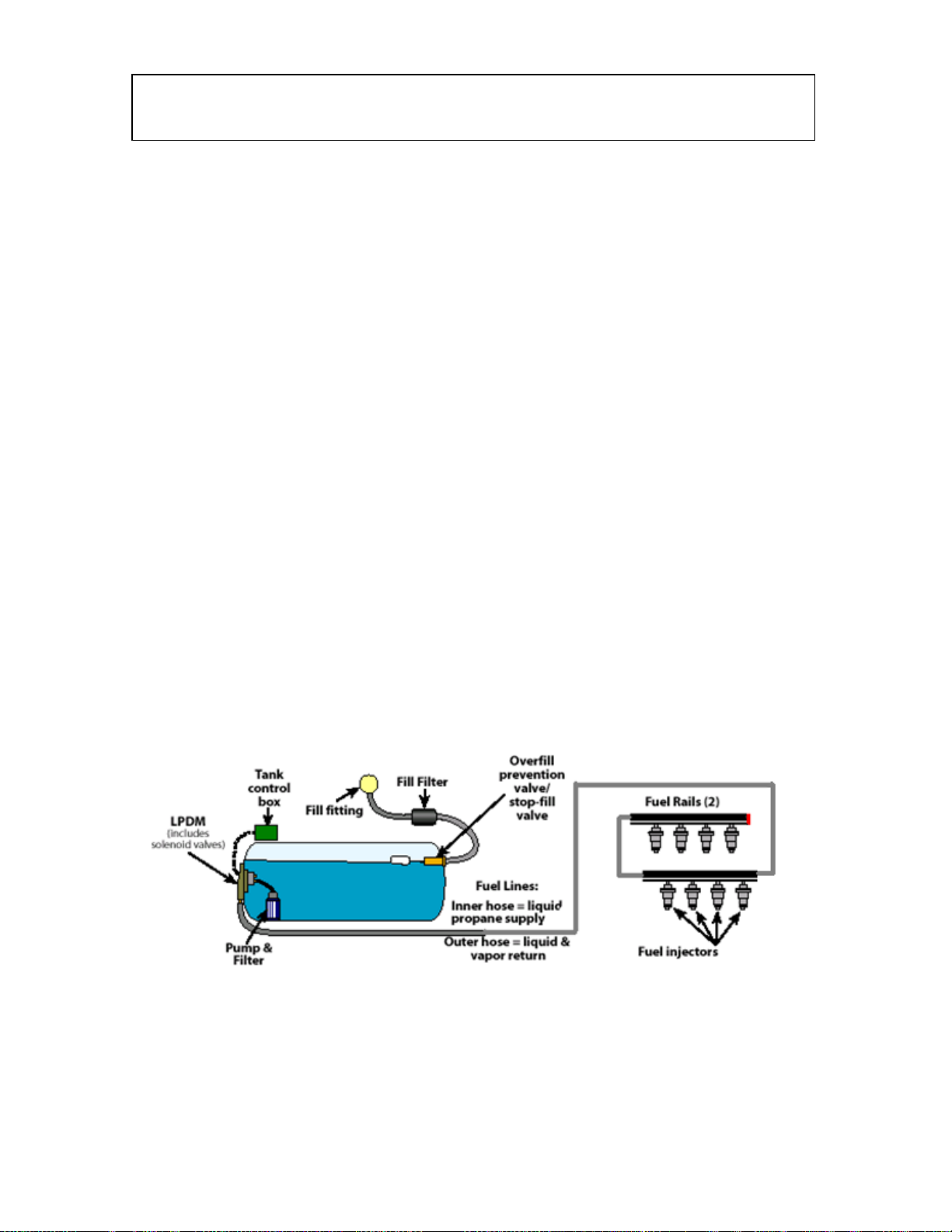
system consists of three main components: the tank, the fuel lines and the injectors. The tank
is located to the rear or middle of the vehicle and the lines are routed forward to the engine compartment
where the injector rail assemblies are mounted in the same position as the original gasoline injector rails
were installed.
The Tank (ASME design, 312.5 p.s.i. working/design pressure)
The fuel tank is the most complicated area of the system. It includes an internal electric fuel pump & filter,
fuel supply & return valves, baffle that keeps the pump submerged in liquid propane and various other
valves, fuel level float assembly, pressure relief valve, overfill prevention device, and liquid service valve.
LPEFI
fuel delivery to the injectors and an optional tank, which only transfers fuel to the main fuel tank based on
fuel level inputs to a transfer module. The main fuel tank fuel pump increases or boosts the tank pressure
by 35 to 50 psi. No matter what the propane tank internal pressure is, the pump boost remains the same.
This is how the propane stays a liquid throughout the liquid supply section of the system. The fuel is
supplied to the injectors and whether the injector is open or not fuel passes through a cooling bushing in the
injector and is returned to the tank. This is called a refrigeration cycle and also aids in maintaining the fuel
in a liquid state throughout the supply passageways in the system. Because propane easily vaporizes, when
the refrigeration cycle stops (when the engine is turned off) or if the return valve malfunctions closed, the
propane will vaporize and cause a loss in power or hard hot restarting. To help in hot restarting, the system
goes through a purge cycle for 10 to 15 seconds before every start up attempt. This strategy is built into the
system’s electronic tank control box. See more about hot restart/hot soak in this manual.
vehicles may have one or two tanks. If it is fitted with two tanks, a main tank, which controls all
8
Page 10
Bi-Phase Technologies
LPEFI Theory & Operation
The Fuel Lines
The fuel lines consist of two flexible hoses, one inside the other, in a concentric arrangement. The nylon
inner line supplies liquid propane to the injectors while the area between the outside of the inner line and
the larger outer hose is the fuel return passage.
The concentric fuel line design has a number of benefits:
1. Cuts the number of possible leak points in half,
2. Reduces vapor-lock in the supply line by using the return fuel passage as insulation,
3. Postpones the vapor-lock that occurs after a hot engine is shut off,
4. Shortens the purge cycle time needed to restart a hot engine.
The Injectors
The LPEFI
injectors that they replace. The injector electrical circuit resistance value is 13-15, similar to a gasoline
injector.
Each fuel injector has a supply passage and a return passage. The fuel injector rails have the same
concentric design as the fuel lines. The passage in the injector from the supply section to the return section
is restricted by a cooling bushing. As liquid propane passes through the cooling bushing, a pressure
reduction takes place, which causes the propane to vaporize and effectively cools the area around the
supply section. This is called a refrigeration cycle and aids in maintaining the fuel in a liquid state for all
driving conditions, regardless of the outside temperature.
The injector delivers propane in a liquid state into the intake port. It vaporizes immediately upon exiting
the injector. This rapidly expanding liquid cools the incoming air to the engine often resulting in a little
more horsepower than the gasoline system could achieve, not to mention the inherently improved exhaust
emissions that propane is known for.
system injectors are designed specifically for liquid propane. They mimic the gasoline fuel
9
Page 11
L
I
g
10
Bi-Phase Technologies
PEF
Basic Dia
nostics
All Models
Introduction
The following diagnostic steps may help prevent overlooking a simple problem. The first step in
diagnosing any drive-ability problem is verifying the customer’s complaint with a test drive under the
conditions the problem reportedly occurred.
Always perform a careful and complete visual inspection first. Most engine control problems result from
mechanical breakdowns, poor electrical connections or damaged/misrouted vacuum hoses. Before
condemning the LPEFI
Visual Inspection
Visually inspect all electrical wiring, looking for chafed, stretched, cut or pinched wiring. Ensure electrical
connectors fit tightly and are not corroded. Visually inspect for any loose or drop harness looms coming in
contact with the injector rails or components. Visually inspect all vacuum hoses and ensure they are
properly routed – not pinched, cut or disconnected. Visually inspect the secondary ignition wires, spark
plugs and ignition coils. Ignition weakness shows up much sooner on propane fueled engines than a
gasoline engine. Visually inspect each, injector insulator housing for cracks, cuts or o-ring sealing at the
manifold or at the top o-ring of the insulator housing (injector repair in this manual). Listen to the fuel
pump operation and the opening “click” of the fuel supply valve. Initiate a purge cycle by turning the
ignition key to the on position (purge logic chart in this manual).
Preliminary Checks
Check that the following systems and components are in good condition and operating properly before
diagnosing problems in the LPEFI
1. Battery condition
2. State of tune (ignition system)
3. All wiring and vacuum connections
4. Air cleaner and ducting
5. Cooling system
Mechanical Inspection
system, perform each test listed in this article.
fuel system.
Warning: DO NOT use the ignition switch during compression test on fuel injected
vehicles. Use a remote starter to crank the engine. Fuel injectors on many models are triggered by
the ignition during cranking mode, which can cause a flammable fuel mixture in the intake manifold
when performing a compression test.
Compression – Check engine mechanical condition with a compression gauge, vacuum gauge or an engine
analyzer. Compression pressures are considered within specifications if the lowest reading cylinder is
within 75 percent of the highest reading cylinder.
Page 12
L
I
g
11
Bi-Phase Technologies
PEF
Basic Dia
nostics
Mechanical Inspection, cont’d
Exhaust system back pressure – The exhaust system can be checked with a vacuum or pressure gauge.
Remove the O
exhaust back pressure is greater than 1¾ to 2 psi., the exhaust system or catalytic converter is plugged. If a
vacuum gauge is used, connect the vacuum gauge hose to an intake manifold port and start the engine.
Observe the vacuum gauge. Open the throttle part way and hold steady. If the vacuum gauge reading
slowly drops after stabilizing, the exhaust system should be checked for a restriction. Also, if the vacuum
gauge will not drop below 3” Hg on a wide open throttle condition or WOT loaded condition, check the
exhaust system for restriction. Leaks in the exhaust system, if upstream from an O
fuel control problems due to oxygen dilution in the exhaust, which causes inaccurate O
sensor and connect a 0-5 psi pressure gauge. Run the engine at 2500 RPMs and if the
2
sensor, can also cause
2
sensor response.
2
Fuel System
Engine does not crank – Check for hydrostatic lock (water or liquid in a cylinder). Repair as needed.
Check for starting and charging system problems.
Engine cranks but will not start
1. Check fuel tank contents and fuel gauge accuracy
2. Check ignition system for good secondary current at the spark plugs – if no spark exists or if spark
is weak, repair ignition system problem first
3. Check fuel lines and fittings for leaks – if no leaks are found, check fuel delivery system for
proper pressure; check for +12 volts to fuel delivery system
4. Check for defective fuel injector; a leaking fuel injector could cause a rich (flooded) condition and
cause a no-start; initiate a purge cycle and after the purge cycle is complete listen at the intake
manifold for injector leaks; open the throttle plate, smell and listen, pull the PCV valve and smell
and listen, lift the injector rail out of the manifold (without disconnecting fuel line) and visually
inspect
5. Check the ECT, coolant temperature sensor – confirm the ECT is in proper working condition
and; if the sensor is faulty
Warning: Always relieve fuel pressure before disconnecting any fuel injection related
component. DO NOT allow uncontrolled fuel release. Never loosen fittings or vent any
propane unless you are wearing insulated PVC rubber gloves; escaping liquid propane can
cause frostbite and severe freeze burns. Do not disconnect any propane hoses or remove any
injectors unless the fuel lines have been properly drained completely. Never release fuel
indoors or in an area where vapors could accumulate – source of ignition could ignite the air
fuel mixture and cause severe injury and property damage.
Fuel Pressure Release
To prevent the fuel pump and fuel supply valve from opening during repair, disconnect battery and/or
electronic tank control box – always disconnect negative battery terminal first.
1. Remove the fuel system Schrader Valve cap on the LPDM
2. The fuel pressure test gauge has a long drain hose; route the drain hose to a flare stack or other
receptacle for flammable propane vapor; never release propane indoors
3. Install the brass collar from the fuel pressure test gauge to the Schrader Valve, with the grooved
end facing out
Page 13
L
I
g
12
Bi-Phase Technologies
PEF
Basic Dia
nostics
Fuel Pressure Release, cont’d
4. Make sure the small thumb valve next to the gauge on the Bi-Phase gauge set is closed
5. Connect the test gauge to the collar; this connection will press the center pin on the Schrader
Valve releasing propane into the hose; this is a sensitive connection and must be confirmed; if the
pressure gauge does not react or reacts slowly, push in on this connection to confirm it has
penetrated the center pin of the Schrader Valve; the brass collar has some adjustments and may
also require oiling the o-ring occasionally
6. Open the valve near the pressure gauge to drain the propane through the long hose; note that the
Schrader Valve does not drain the tank – it only drains the main fuel line and the injectors
7. When the gauge reads “0” and there is no pressure exiting the end of the hose, you may disconnect
the fuel lines or injectors as needed (more detailed procedures and photos on page 36)
Warning: Do not remove the LPDM or any tank valves from the tank at this time.
Propane tank is under pressure. The procedure described previously only drains the fuel
lines for service. Serious injury or death could occur.
Fuel Pressure
Internal tank pressure must be established first. Use the 3-switch diagnostic box from Bi-Phase
Technologies, turn on the fuel supply valve rocker switch and push the fuel return valve “push” switch.
Hold down the fuel return valve switch for 30 seconds or until fuel pressure stabilizes. This is internal tank
pressure. When checking fuel pressures over a given time always recheck internal tank pressure due to
changes in ambient temperature.
When diagnosing the system it is very important to consider this information as it affects the accuracy of
your diagnosis. Boost Pressure = 35 to 50 p.s.i. (pressure over internal tank pressure)
Fuel pressure with return valve open (all models) – With the return valve open or during a purge cycle
the fuel pressure will be 5 to 15 psi below normal operating pressure (internal tank pressure plus boost
pressure). Should the pressure drop more than 15 psi. evacuate the fuel in the fuel lines (reference the
procedures in this manual), remove the primary hose and inspect the white nylon inner liquid supply line in
the primary hose at the LPDM. It could require that you visually inspect all hoses for proper inner liquid
supply line length.
Fuel pressure should always be confirmed first. If fuel pressure is not within specification the system will
malfunction. Fuel pressure can cause many types of drive ability complaints.
Page 14
Bi-Phase Technologies
LPEFI Basic Diagnostics
13
Concentric Fuel Lines
As previously discussed, the fuel lines of the LPEFI
supply and fuel return to be accomplished inside one fuel hose. There are many benefits to this design as
mentioned in the theory section of this manual.
The sealing of the white nylon inner line to all the specific components of the system is very critical. If this
seal is lost, damaged or not made the vehicle will experience hard starting when hot, reduced power under
load, unbalanced injectors (rail to rail or bank to bank) and in extreme cases a no-start condition.
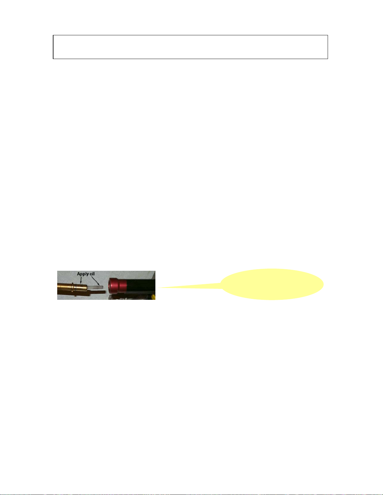
It is very difficult to install the lines and caution should be taken when assembling the concentric fuel lines
that connect from the LPDM and the injector rails. The inner lines are small and easily crimped (kinked)
during installation to the fuel rail. Also damage to the O ring seal in the rail may occur. It is recommended
to coat the metal hose end fitting and the white nylon inner line with clean motor oil before attempting
installation. If the white nylon inner line is crimped during installation or repair of the system a new hose
assembly must be obtained. The white nylon inner line is custom fit to each larger outer hose. Do not
assemble the hose with a crimped inner line; it will cause drive-ability problems. Years of process
development have caused the installation to be more difficult. However, at this time there is no other way
to rely on a proper fit and reliability.
Each white nylon inner line is sealed by a single o-ring located below the inner line alignment bushing
(finger bushing). This is found in each hose port whether it is the LPDM, or the injector rail end fitting.
See illustration below.
system are a concentric design. They permit fuel
Injector rail end fitting & hose
utilizing quick disconnect
much like gasoline
Page 15

Bi-Phase Technologies
LPEFI Basic Diagnostics
Fuel Injectors
Fuel Injector check
1. Connect a tachometer to the engine; run the engine at idle; disconnect and reconnect injectors
individually (this may also be accomplished with a scan tool); if each injector causes a momentary
drop in engine speed of at least 100 RPMs, injectors are giving proper fuel delivery; RPM drop
should only be momentary as the IAC (idle air control) will attempt to reestablish correct idle
RPM
2. Replace any injectors that do not cause sufficient drop in engine speed; when test is complete, turn
engine off; to check curb idle, refer to the emission control specification on the decal in the engine
compartment or the OEM service manual for the particular vehicle
3. With the system pressurized listen, smell, spray with leak detection fluid and visually inspect
injectors for fuel leaks from the injector tip and housing; open the throttle plate to listen and smell,
or without disconnecting the fuel lines lift the injector rail out of the intake manifold to visually
verify that no injector leaks fuel; if an injector sprays fuel or leaks externally without an electrical
demand, the injector must be replaced
4. The fuel injector housing is a heat insulator and is installed over the injector itself, even though it
may look as one piece; the injector insulator housing is sealed onto the injector with one or two
o-rings, depending on the design revision level of the injector; the early single o-ring sealed
injector housing may lose its seal causing a vacuum leak; an injector should hold a vacuum if
checked from the bottom of the housing with a hand operated vacuum pump (reference injector
repair in this manual)
5. The fuel injectors are calibrated for each specific engine; injectors are also assembled on each rail
within a specific range of flow; if an injector from a different engine family is installed it could
cause an out-of-balance situation and set a diagnostic trouble code in the PCM
Fuel injector circuit – Disconnect all injector harness connectors. Use a digital ohmmeter to check
resistance across the terminals of each injector. The nominal resistance for each injector is 12.6 to 13.8Ω.
An acceptable range is 12Ω to 15Ω, but not to exceed 2Ω between the lowest reading injector to the highest
reading injector. If there is greater than 2Ω difference, choose and replace the highest or lowest resistance
injector, whichever corresponds, to achieve a range inside 2Ω. If the resistance test proves an open circuit
the injector must be replaced. Refer to the OEM service manual and wiring diagram for more information
if the wiring harness is at fault.
Ignition Checks
(Note: On many newer vehicles if an ignition failure occurs, the ignition system may continue to operate
with limited ability. Diagnostic trouble codes should be present if this occurs and the engine may be hard
to start. The ignition timing will also be fixed or no change in timing with RPM or load changes.)
Initial Inspection
1. Visually inspect ignition system components and wiring for evidence of damage or loose
connections; check condition of spark plugs, spark plug wires and distributor cap and rotor (if
equipped); repair or replace damaged components
2. Ensure idle speed and ignition timing is correct; check all components that could affect ignition
timing; refer to OEM specifications
Crankshaft position sensor
Camshaft position sensor and/or sensor timing
Crankshaft end play
Timing belt or timing chain condition, worn timing gears, chain or belt can cause erratic
timing
MAP or MAF sensor signals
For more detailed information refer to the OEM repair manual
3. Ensure spark plug wires are properly connected and routed in correct firing order
14
Page 16

Bi-Phase Technologies
LPEFI Basic Diagnostics
Ignition Checks, cont’d
4. Check for spark – Disconnect a spark plug wire from a spark plug; connect a spark plug tester
between the spark plug wire and ground; crank engine and check for a strong consistent spark;
repeat test for each spark plug wire; if no spark is present check ignition coil primary wiring, coil
output or refer to OEM repair manual; if spark appears to be inconsistent do the same as
previously mentioned, but confirm the condition of the spark plug wire and repeat test; an ignition
scope analyzer is also recommended for checking ignition condition; an approved spark plug tester
must be used to prevent damage to ignition control components
5. Using a digital ohmmeter check the resistance of each spark plug wire; high tension wire
resistance should be 4000 to 7000Ω per foot; replace as necessary
6. Check power to coil – Disconnect primary wiring to coil/coils; turn on ignition and measure
voltage of primary positive voltage wire to coil connector; if less than 10 volts repair battery
condition or primary positive voltage wire
7. Check coil/coils – Disconnect coil, using a digital ohmmeter measure resistance of ignition coil
between primary wire terminals; measure resistance between ignition coil’s secondary terminals
and positive primary terminal; refer to appropriate OEM repair manual for exact resistance values
15
Page 17

Bi-Phase Technologies
LPEFI Electronic Engine Management
16
Introduction
The LPEFI
engines. The design intent was to allow direct replacement of the gasoline fuel system to the LPEFI
system was developed and designed for use on modern sequential fuel injected gasoline
system with no change in the original gasoline electronic engine control strategy or onboard diagnostics.
With this said, it is very important that a technician understands electronic engine management theory. In
this section we will not attempt to write the book on electronic engine control or self-diagnostics, but
briefly explain some theory and operation of the general idea of electronic engine management and some
areas that will help in the diagnosis of the LPEFI
system. For details on specific vehicles you should refer
to the OEM repair manuals.
Electronic Engine Management
Power-train control module – The PCM monitors engine operating conditions by input received from
engine sensors. Control output actuators supply the function of fuel supply, incoming air, timing, ignition,
EGR, evaporative emission control to provide the demanded operating condition the driver or the PCM
desires based on the inputs from the engine sensors. The implementation of electronic engine management
brought many benefits:
1. Improved exhaust emissions,
2. Improved power,
3. Improved fuel economy,
4. Improved durability & reliability, and
5. On-board self diagnostics.
Since the first generations of electronic engine management, about 1980, many improvements have been
made. Today all vehicle manufacturers comply with the standards of OBD II (on-board diagnostics second
generation). OBD II did drastically change the way electronic engine management is carried out but it did
not change the original input versus output control strategy. It did require that the names for sensors and
actuators used are common from manufacturer to manufacturer, the same data link connector be used and a
generic list of trouble codes and data are retrievable by aftermarket diagnostic scan tools. In addition, more
monitors were added to track degradation of emission control components and warning flags that would
turn on the malfunction indicator lamp for things like cylinder misfire or catalytic converter failure.
Manufacturers began implementation of OBD II as early as 1994 on select vehicles with a goal to be
completed with light duty trucks by 1996. Today, they are still adding to it and implementing it on heavier
vehicles.
The engine control system consists of the PCM, relays, modules, sensors, switches and actuators. The
PCM sends out electrical reference signals to engine sensors and then analyzes the return signals. The
engine sensors supply specific information to the PCM, in the form of electrical signals, to determine
engine operating conditions.
In the event of a sensor or actuator failure, the PCM initiates an alternative strategy or failure mode to
allow the vehicle to maintain drive ability. In the event of PCM failure a limited operating strategy will be
activated. This provides minimal engine operation and any self-test or feedback systems will stop. The
malfunction indicator lamp will come on and stay on until the vehicle is repaired or until the PCM has
determined that all signals have returned within operating limits and then the PCM will resume normal
operation.
Vehicles are equipped with different combinations of input devices. Not all devices are used on all models.
To determine the input devices used on a specific model refer to the appropriate OEM repair manual and
wiring diagrams.
Page 18

Bi-Phase Technologies
LPEFI Electronic Engine Management
17
Electronic Engine Management, cont’d
Some common input devices
Crankshaft position sensor
Camshaft position sensor
Engine coolant temperature sensor
Inlet air temperature sensor
Oxygen sensor
Throttle position sensor
Mass air flow sensor
Manifold absolute pressure sensor
Vehicle speed sensor
EGR position sensor
Knock sensor
Output signals are signals that send a demand to an actuator; some common actuators
Fuel injectors
Fuel pump
Idle air control or idle speed control
EGR control
Canister purge control solenoid
Spark control
MIL (malfunction indicator lamp)
Transmission controls
There are many more inputs and outputs, these are some common ones. Vehicles are equipped with
different combinations of computer-controlled components. Not all vehicles are equipped with the same
components. Always refer to the specific OEM repair manuals and information.
Self-Diagnostics
With the capability to see data through the use of a scan tool and to verify areas of trouble by checking for
diagnostic trouble codes, today’s electronics have given us more ways to verify where and what the
problem might be. Each vehicle manufacturer has written steps in troubleshooting a vehicle. If the scan
tool leads you to a specific trouble area refer to the OEM written test to troubleshoot accurately. Some
aftermarket manuals are very good in diagnosing electronic engine controls.
To prevent the replacement of good components and wasting precious time, verify engine condition and
basic tune-up requirements before condemning electronic engine control components. If your scan tool
immediately warns of a bad sensor, check it first but remember that an out-of-tune engine or an engine with
internal mechanical deficiencies can trigger diagnostic trouble codes.
DTCs, diagnostic trouble codes, are generated when there is a gross error with a sensor signal, input or
output signal or the PCM can no longer control something, meaning fuel mixture, timing, EGR, canister
purge and so on. Many times a DTC is generated but the fault is not necessarily the same as the DTC. For
example, a vacuum leak may cause an oxygen sensor activity code or a fuel control code. In this situation
the vacuum leak is the problem but it affected the electronic control of fuel which could cause you to
replace an injector if you did not check thoroughly or even the replacement of an oxygen sensor.
Always remember the basics and eliminate all the easy things first.
Page 19

Bi-Phase Technologies
LPEFI Electronic Engine Management
18
Self-Diagnostics, cont’d
Retrieving DTCs, diagnostic trouble codes, is always a good place to start when trouble shooting a
problem. If there are multiple DTCs, you need to evaluate them and troubleshoot with the first DTC listed.
Write down all the DTCs listed and investigate what each one stands for. Open up the data information
available and investigate the area of concern established by the DTCs listed. See if there is any correlation
between the DTC and the data associated with it. Many times you may find that the data reveals proper
function and there is no reason for generating a DTC. If this is the case, look at the freeze frame data, if
available, and see under what conditions the DTC was generated. This will help in diagnosing the problem.
The data information is very helpful. First, you can look at sensor and actuator activity live. This is very
effective diagnostics. Today, it is very important that a technician knows and understands on-board
diagnostics. It can save time and money, which benefits both the technician and the customer.
When diagnosing the LPEFI
stream.
ECT (engine coolant temperature)
IAT (intake air temperature)
IAC (idle air control)
STFT B1 and B2 (short term fuel trim bank 1 and bank 2)
LTFT B1 and B2 (long term fuel trim bank 1 and bank 2)
PW B1 and B2 (average injector pulse width bank 1 and bank 2)
02S11 (oxygen sensor bank 1 front sensor)
02S21 (oxygen sensor bank 2 front sensor)
It is very important that you know the meaning of the PID (parameter identification) names in the data
stream and understand the values displayed. In this manual we will only talk about a few of these terms.
Refer to OEM repair manual for a more detailed explanation. Many of the PID addresses are easy to
identify but some of the acronyms are confusing, and having an OEM repair manual or Mitchell manual is
very helpful. The more you work with electronic diagnostics the more familiar you will become.
Important PIDs, Explanation
ECT (engine coolant temperature) – The data is displayed as degrees F or C depending on your selection
for English or metric display. Engine coolant temperature is important because the learning function of the
computer does not begin until the engine reaches a programmed temperature. This temperature may vary
depending on vehicle model. For example a Ford may not begin to learn until the temperature reaches 165
degrees F. Always perform final diagnosis when the engine is at full operating temperature.
IAT (intake air temperature) – The data is displayed as degrees F or C depending on your selection for
English or metric display.
IAC (idle air control) – The data is displayed in % or counts. % is the percent of time it is on, 50% would
be half open or 75% would ¾ open. Counts would be the same, the higher the count the more open the
valve is. This could be important when a vacuum leak is suspected. Always refer to the OEM repair
manual for the operating range as each model varies.
STFT B1 or B2 (short term fuel trim) – This is displayed either in positive or negative percentages (%) or
in counts. Short term fuel trim is adjustments to fuel delivery, as it is happening at the moment you look at
it. The closer to 0% or 128 counts the better the fuel control is. A negative percentage indicates a rich
condition and the fuel control is subtracting fuel or adjusting the fuel delivery leaner while a positive
percentage is a lean condition and fuel control is adding fuel or adjusting the fuel delivery richer.
system, there are some PID values you may want to look at from the data
Page 20

Bi-Phase Technologies
LPEFI
Electronic Engine Management
19
Important PIDs, Explanation
STFT B1 or B2, cont’d
If it is displayed in counts the range for counts is 0 to 255. The middle of the range is 128 and any reading
less than 128 is a rich condition while any reading greater than 128 is a lean condition. This does not mean
the engine is running rich or lean, but means that fuel delivery is rich/lean and fuel control is adjusting from
that point to optimize fuel delivery for emissions, economy and drive ability. If the range of control
reaches the limit, lean or rich, then the engine is running lean or rich and the computer can no longer
control the fuel mixture and a DTC will be logged in the computer’s memory. If the computer recognizes
this in a second drive cycle it will illuminate the MIL, (malfunction indicator lamp or check engine light).
The STFT has a back up to extend its range of control. It is called LTFT, long term fuel trim, and if the
STFT is controlling too far to the lean or rich side of the middle of the range of control, the LTFT will learn
and allow the STFT to control closer to the middle of the range. This allows the STFT to have a much
longer time period of control. This allows the degradation of the air filter, the fuel filter, fuel injectors,
engine oil contamination, PCV, fuel pump and anything that can affect fuel and air delivery. For example,
when a very dirty air filter is replaced the fuel control will readjust over time or the same with a fuel filter
or the same after an injector is replaced.
LTFT (long term fuel trim) – This is displayed in either positive or negative percentages (%) or in counts.
It is also shown for bank one and bank two. Long term fuel trim is adjustments to fuel delivery over time.
The closer to 0% or 128 counts the better the fuel control is. A negative percentage indicates a rich
condition and the fuel control is subtracting fuel or adjusting the fuel delivery leaner, while a positive
percentage is a lean condition and fuel control is adding fuel or adjusting the fuel delivery richer. If it is
displayed in counts the range for counts is 0 to 255. The middle of the range is 128 and any reading less
than 128 is a rich condition while any reading greater than 128 is a lean condition. This does not mean the
engine is running rich or lean, but means that fuel delivery is rich/lean and fuel control is adjusting from
that point to optimize fuel delivery for emissions, economy and drive ability. If the range of control
reaches the limit, lean or rich, then the engine is running lean or rich and the computer can no longer
control the fuel mixture and a DTC will be logged in the computer’s memory. If the computer recognizes
this in a second drive cycle it will illuminate the MIL, (malfunction indicator lamp or check engine light).
LTFT levels adjust over time as previously mentioned and causes or allows the STFT to maintain control
closer to the middle of the control range. This allows rapid changes to fuel control for better response and
performance. The LTFT is like a fine-tuning function. This gives the STFT a much longer time period of
control. This allows the degradation of the air filter, the fuel filter, fuel injectors, engine oil contamination,
PCV, fuel pump and anything that can affect fuel and air delivery. For example, when a very dirty air filter
is replaced, the fuel control will readjust over time or the same with a fuel filter or the same after an
injector is replaced. If the battery is changed or disconnected it will reset fuel trim and a learning process
could take a few hundred miles. However, for diagnosis purposes bringing the vehicle to full operating
temperature and a short drive will give you an idea of where the controls stabilize. Anytime the STFT
values are stabilized close to the middle of the range of control the LTFT values should be accurate. If the
air filter is clean, the engine oil is not contaminated and the engine condition is good the LTFT values are a
good indicator of how well the injectors are calibrated. It is also helpful to review the LTFT values at
different load conditions, such as cruising at 45 mph or at a wide open throttle situation. If power seems
low and wide open throttle values are very lean this would give you something to look for.
Page 21

20
Bi-Phase Technologies
LPEFI Electronic Engine Management
Important PIDs, Explanation, cont’d
The LPEFI
gasoline injectors. What we want to look for when diagnosing the LPEFI
within 10% or about 40 counts of each other. For instance –2% bank one and –8% bank two would be
okay. It is normal to also see LTFT values at -17% on either bank but we would not want to see a richer
condition or -20% numbers. If the LTFT values are on the leaner end of the control range, other problems
may exist if the value is higher than +12% or 176 counts. Four counts equal approximately 1%.
system will not have LTFT values as good or as close to the middle of the control range as
system is for the values to be
PW (injector pulse width) – The length of time the injector solenoid is energized or the injector is open,
displayed in milliseconds and averaged for each bank of the engine. Naturally the injector pulse width is
lower at idle than it is at cruise and higher than cruise during a loaded condition. Comparing the PW values
could identify an area of concern. For example, if you identified a weak injector during the fuel injector
check in the basic diagnostic procedure section of this manual, it could show up here by displaying a
different PW on the bank that had the weak injector. Most of the time, injector pulse width will be between
2 and 5 milliseconds at idle. The scan tool only displays an average pulse width for each bank of cylinders.
Each bank is normally within a few tenths of each other. If not, refer to checking fuel injectors in basic
diagnostic procedures.
O2S11 or HO2S11 – Oxygen sensor or heated oxygen sensor bank one sensor one
O2S21 or HO2S21 – Oxygen sensor or heated oxygen sensor bank two sensor one
Most oxygen sensors today are equipped with an internal heater to speed up the amount of time it takes for
electronic engine management to reach closed loop. An oxygen sensor is not active until it reaches a
temperature of approximately 570 degrees F. Oxygen sensors create voltage and can be called a galvanic
battery. A low voltage signal is a lean fuel mixture indication and a high voltage signal is a rich fuel
mixture indication. The maximum voltage an oxygen sensor will generate is approximately 1000 millivolts
or one volt. The oxygen sensor actually measures oxygen content in the exhaust stream. If a rich mixture
exists, there is a lack of oxygen compared to the outside ambient atmosphere. This lack of oxygen causes
the oxygen sensor to create voltage. If the amount of oxygen in the exhaust stream is equal to the amount
in the atmosphere, no voltage will be generated. Oxygen sensors are sensitive to silicones and could
become coated and decrease the reaction time or activity. Oxygen sensor signal is something worth
verifying and not only at idle, but at different engine load conditions. Most vehicles today consider an
oxygen sensor signal of 0.45 volts as stoichiometric. The fuel control is based on oxygen sensor voltage
and if fuel control is working properly, oxygen sensor voltage will move below and above the 0.45 volts.
The number of times in a given period that the oxygen sensor signal crosses above or below the 0.45 volts
is called cross counts and the PCM monitors this activity to know how fuel control is functioning as well as
for fuel delivery decisions.
Page 22

L
I
g
21
Bi-Phase Technologies
PEF
Pressure Testin
the LPEFISystem
3 Switch Box Test Switches
3 Switch Box Connectors
Page 23

22
Bi-Phase Technologies
LPEFI Pressure Testing the LPEFI
System
Page 24

Bi-Phase Technologies
LPEFI Pressure Testing the LPEFI
System
23
Page 25

24
Page 26

25
LPEFI® Purge Logic
Page 27

L
I
g by Symp
26
Bi-Phase Technologies
PEF
Troubleshootin
Introduction
Before diagnosing symptoms or intermittent
faults, perform steps in basic diagnostic
procedures and appropriate self-diagnostics with
a scan tool. Use this section to diagnose
problems existing when DTCs, diagnostic
trouble codes, are not present.
Symptom checks can direct the technician to
malfunctioning component(s) for further
diagnosis. A symptom should lead to a specific
component test and/or adjustment.
Symptoms
Symptom checks cannot be used properly unless
the problem occurs while the vehicle is being
tested. To reduce diagnostic time, ensure basic
diagnostic procedures and self-diagnostics were
performed before diagnosing a symptom. Some
symptoms are:
No crank
Hard start cold/long crank
Hard start hot/long crank
No start/normal crank
Low idle speed
High idle speed
Rough idle
Stalls but restarts (hot or cold)
Stalls but does not restart
Stalls during acceleration
Stalls during deceleration
Stalls during steady speed driving
Stalls after vehicle stops
Stalls when put in gear
Stalls while idling
Starts but stumbles and stalls
Hesitates
Surges
Backfires, misfires or cuts out during
acceleration
Backfires, misfires or cuts out during
deceleration
Bucks & jerks
Engine knocks or rattles, spark knocks
Loss of power during cruise or all the time
Loss of power during heavy load condition,
wide open throttle
Poor fuel economy
Failed emissions
tom
Runs rough all the time
High oil consumption
Engine runs hot
Engine runs cold
Fire comes out of exhaust
LPEFI
Smell of propane
Slow fuel filling or no fill
Unable to evacuate fuel lines through
No fuel transfer from optional secondary
Noisy fuel pump or noise in tank
Fuel pump does not shut off
No purge cycle
Injector leaks with no electrical command
Injector insulator housing cracked or not
Specific Symptoms
Schrader Valve
transfer tank
sealing (vacuum leak)
Symptom Diagnosis
No Crank
Check battery connections
Check the start motor
Check appropriate fuses and fuse links
On A/T models check park/neutral safety
switch
On M/T models check clutch switch
Check starter circuitry
Check for seized/hydro locked engine
Check flywheel
Check ignition switch
Hard start cold/long crank
Check battery charge condition
Check ignition primary voltage during crank
& secondary wiring
Check for vacuum leaks
Check fuel pressure (pump boost)
Check injectors for leakage, causing a
rich/flooded condition
Check air cleaner & incoming air ducts
Check engine mechanical condition,
compression
Page 28

Bi-Phase Technologies
L
I
g by Symp
PEF
Troubleshootin
27
tom
Symptom Diagnosis, cont’d
Hard start hot/long crank
Check battery charge condition
Check ignition primary voltage during crank
& secondary wiring
Check for vacuum leaks
Check fuel pressure (pump boost)
Check injectors for leakage, causing a
rich/flooded condition
Check air cleaner & incoming air ducts for
restriction
Check nylon inner liquid supply fuel lines
and the o-ring seals for the nylon inner line
Check engine mechanical condition,
compression test
No start/normal crank
Check battery charge condition & fuel level
Check the LPEFI
Check ignition primary voltage during crank
& secondary wiring
Check for vacuum leaks
Check fuel pressure including operation of
pump and supply & return valves
Check wiring at electronic tank control box
Check injectors for leakage, causing a
rich/flooded condition
Check air cleaner & incoming air ducts for
restriction
Check injector wiring harness & individual
injector connectors
Check injector power wire voltage
Check that injectors are delivering fuel
Injector diagnosis
Low idle speed
Check idle air control wiring harness
connector or ETC, if equipped
Check base timing
Check engine mechanical condition,
compression test
Confirm IAC/ETC controls idle speed
Check and/or adjust minimum idle, refer to
OEM repair manual for specification
Check air cleaner and incoming air ducts
High idle speed
Check IAC/ETC wiring harness connector
Check base timing
Confirm IAC/ETC controls idle speed
Check for vacuum leaks
Check intake manifold gasket for vacuum
leaks
Check and/or adjust minimum idle, refer to
OEM repair manual for specification
system 30-amp fuse
Check EGR valve
Check throttle linkage
Check throttle plate for a closing obstruction
Check incoming air intake ducts
Check PCV
Check canister purge vacuum lines &
evaporative emissions lines, if equipped
before the LPEFI
Rough idle
Check ignition secondary wiring
Check spark plugs
Check for vacuum leaks
Check PCV
Check air cleaner and incoming air ducts &
sealing around MAF sensor
Check fuel injector wiring harness and
individual injector electrical connectors
Check fuel system operating pressure
Check fuel injectors, conduct balance test as
described in basic diagnostic procedures
Check engine mechanical condition,
compression test
Check cooling fan blades for cracks or
bends
Check for broken engine mounts
Check all wiring connectors for intermittent
failure/disconnect
Check for flooded condition/leaking fuel
injector, see basic diagnostic procedures
system installation
Page 29

L
I
g by Symp
Bi-Phase Technologies
PEF
Troubleshootin
28
tom
Symptom Diagnosis, cont’d
Stalls but restarts (hot or cold)
Check and/or adjust minimum idle speed per
the OEM repair manual specification
Check IAC/ETC wiring harness connector
Confirm IAC/ETC controls idle speed
Check for vacuum leaks
Check PCV
Check for restricted air cleaner or incoming
air ducts
Check MAF
Check exhaust for restriction, see basic
diagnostic procedures
Check EGR valve
Check engine mechanical condition,
compression test
Verify there are no leaking fuel injectors,
see basic diagnostic procedures
Check for lean fuel injectors, verify long
term fuel trims
Check fuel pressure
Check wiring & wiring harness connectors
for intermittent failure/disconnect at
electronic tank control box and all LPEFI
wiring connections & OEM connections
Stalls but does not restart
Check fuel pressure and confirm the
LPEFI
system refrigeration cycle is
working, i.e. inner liquid supply line not
sealing, fuel pressure is too low, fuel return
valve malfunction; see basic diagnostic
procedures
Verify ignition voltage is not dropping out,
primary or secondary ignition
Check the LPEFI
system 30-amp fuse
Verify engine is not overheating
Verify engine oil level
Check all wiring connectors for intermittent
failure/disconnect
Check for flooded condition/leaking fuel
injector, see basic diagnostic procedures
Stalls during acceleration
Check all wiring connections
Check ignition voltage & ignition switch
Check primary & secondary ignition voltage
Check for vacuum leaks
Check for excessive lean or rich conditions,
leaking injector
Check exhaust back pressure, see basic
diagnostic procedures
Check for intermittent fuel pump or fuel
supply valve or return valve malfunction
Stalls during deceleration
Check fuel level
Check and/or adjust minimum idle speed per
the OEM repair manual specification
Check IAC/ETC wiring harness connector
Confirm IAC/ETC controls idle speed
Check for vacuum leaks
Check PCV
Check for restricted air cleaner or incoming
air ducts
Check MAF
Check exhaust for restriction, see basic
diagnostic procedures
Check EGR valve
Check engine mechanical condition,
compression test
Verify there are no leaking fuel injectors,
see basic diagnostic procedures
Check for lean fuel injectors, verify long
term fuel trims
Check fuel pressure
Check wiring & wiring harness connectors
for intermittent failure/disconnect at
electronic tank control box and all LPEFI
wiring connections & OEM connections
Stalls during steady speed driving
Check all wiring connections
Check ignition voltage & ignition switch
Check primary & secondary ignition voltage
Check for vacuum leaks
Check for excessive lean or rich conditions,
leaking injector
Check exhaust back pressure, see basic
diagnostic procedures
Check for intermittent fuel pump or fuel
supply valve malfunction
Stalls after vehicle stops
Check fuel level
Check and/or adjust minimum idle speed per
the OEM repair manual specification
Check IAC/ETC wiring harness connector
Confirm IAC/ETC controls idle speed
If equipped with electronic throttle control
check accelerator pedal and throttle plate
control
Check for vacuum leaks
Check PCB
Page 30

L
I
g by Symp
29
Bi-Phase Technologies
PEF
Troubleshootin
Symptom Diagnosis, cont’d
Stalls after vehicle stops, cont’d
Check for restricted air cleaner or incoming
air ducts
Check MAF
Check exhaust for restriction, see basic
diagnostic procedures
Check EGR valve
Check engine mechanical condition,
compression test
Verify there are no leaking fuel injectors,
see basic diagnostic procedures
Check for lean fuel injectors, verify long
term fuel trims
Check fuel pressure
Check wiring & wiring harness connectors
for intermittent failure/disconnect at
electronic tank control box and all LPEFI
wiring connections & OEM connections
Stalls when put in gear
Check and/or adjust minimum idle speed per
the OEM repair manual specification
Check IAC/ETC wiring harness connector
Confirm IAC/ETC controls idle speed
Check for vacuum leaks
Check PCV
Check for restricted air cleaner or incoming
air ducts
Check MAF
Check exhaust for restriction, see basic
diagnostic procedures
Check EGR valve
Check engine mechanical condition,
compression test
Verify there are no leaking fuel injectors,
see basic diagnostic procedures
Check for lean fuel injectors, verify long
term fuel trims
Check fuel pressure
Check wiring & wiring harness connectors
for intermittent failure/disconnect at
electronic tank control box and all LPEFI
wiring connections & OEM connections
tom
Stalls while idling
Check fuel level, insure the fuel pump baffle
area is not running out of fuel
Check and/or adjust minimum idle speed per
the OEM repair manual specification
Check IAC/ETC wiring harness connector
Confirm IAC/ETC controls idle speed
If equipped with electronic throttle control
check accelerator pedal and throttle plate
control
Check for vacuum leaks
Check PCV
Check for restricted air cleaner or incoming
air ducts
Check for interruption in ignition circuit
voltage, primary & secondary; intermittent
voltage drop
Check MAF
Check exhaust for restriction, see basic
diagnostic procedures
Check EGR valve
Check engine mechanical condition,
compression test
Verify there are no leaking fuel injectors,
see basic diagnostic procedures
Check for lean fuel injectors, verify long
term fuel trims
Check fuel pressure
Check wiring & wiring harness connectors
for intermittent failure/disconnect at
electronic tank control box and all LPEFI
wiring connections & OEM connections
Starts but stumbles and stalls
Check fuel level
Complete the purge cycle, repeat the purge
cycle, try purging twice
Verify fuel pressures; pump, fuel supply
valve operation
Check and/or adjust minimum idle speed per
the OEM repair manual specification
Check primary ignition voltage, ignition
switch
If equipped, check electronic throttle
control, (accelerator pedal assembly or
throttle plate actuator)
Confirm injectors are sealing (no leaking
injectors)
Confirm injectors are not leaking a vacuum
(check injector insulator housing seals and
holds a vacuum)
Page 31

L
I
g by Symp
Bi-Phase Technologies
PEF
Troubleshootin
Symptom Diagnosis, cont’d
Hesitates
Check fuel level
Verify fuel pressures; pump, fuel supply
valve operation
If equipped with electronic throttle control,
check accelerator pedal and throttle plate
control actuator
Verify no leaking injectors (injectors leak
fuel when there’s no demand)
Verify no vacuum leaks
Check ignition system, primary & secondary
Perform a hot restart – hot soak for 20
minutes and confirm restart is fast &
smooth; if not, check fuel lines, specifically
inner fuel line sealing or crimped; see hot
soak
Surges
Check fuel level
Verify fuel pressures
Check injectors (fuel leaking/tip leaks or
vacuum leaks)
Check for vacuum leaks
Check ignition system, primary and
secondary
Check EGR valve
Check ignition timing
If equipped, check electronic throttle control
Check PCM control and sensors, MAF,
MAP, O2 sensors, etc; some sensors can
malfunction and not set a trouble code; refer
to OEM guidelines to verify sensor condition
Backfires, misfires or cuts out during
acceleration
Check fuel level
Verify fuel pressures
Check ignition timing, on distributor-less
ignition systems camshaft sensor or
crankshaft sensor could be faulty
Check for vacuum leaks
Check for leaking injectors or vacuum leaks
on injector housings
Check hot restart after 20-minute hot soak
Check ignition system, primary and
secondary
Check O2 sensors, visually monitor scan
tool during failure
30
tom
Backfires, misfires or cuts out during
deceleration
Check fuel level
Verify fuel pressures
eck ignition timing
Ch
Check for vac
Check for leaking injectors (leaking fuel
between pulses causes rich condition
Check long term fuel trim for rich condition
Check ignition system, primary and
secondary
Check injectors, long term fuel trims
injector fuel leaks or vacuum leaks at
injector housings
Check hot restart after 20-minute hot soak
Check O2 sensors, visually monitor scan
tool during failure
Buck & jerks
Check fuel level
Verify fuel pressures
Visually inspect fuel supply inner nylon line
Check ignition system, primary and
secondary
Check EGR valve
If equipped, check ETC (accelerator pedal
and throttle plate actuator)
Check for vacuum leaks
Check O2 sensors, monitor scan tool during
failure
Check hot restart after 20-minute hot soak
Engine knocks or rattles, spark knocks
Check oil level
Check cooling system
Check engine condition
Check ignition timing
Check camshaft and crankshaft position
sensors
Check knock sensor circuit
Check MAF and/or MAP sensors
uum leaks
Page 32

L
I
g by Symp
Bi-Phase Technologies
PEF
Troubleshootin
Symptom Diagnosis, cont’d
Loss of power during cruise or all the time
Check engine compression
Check fuel pressures
Check hot restart after 20-minute hot soak
Check long term fuel trims for very lean
injectors
Check for vacuum leaks
Check MAF and/or MAP sensors
Check ignition system, primary & secondary
Check ignition timing
Loss of power during heavy load condition,
wide open throttle
Check exhaust system, back pressure
Check fuel pressures
Check injectors, long term fuel trims,
injector fuel leaks or vacuum leaks at
injector housings
Check hot restart after 20-minute hot soak
Check ignition system, primary and
secondary
Check incoming air flow, air filter, fresh air
hose to filter
Poor fuel economy
Check incoming air flow, air filter, fresh air
hose to filter
Check fuel injectors, long term fuel trim,
injector fuel leaks
Check for vacuum leaks – vacuum leaks can
cause a lean condition, which causes a rich
fuel demand
Check PCV
Failed Emissions
Slow O2 sensor - Fluid leaks, wrong RTV
Check spark plugs
Check catalytic converter
Leaking injector
Runs rough all the time
Check ignition system, primary and
secondary
Check for vacuum leaks
Check injectors, resistance values for open
circuit
Check engine condition, compression
High oil consumption
Check engine condition, compression
Check PCV
back pressure
Check exha
Check oil change interval, use recommended
oil grade
Engine runs hot
Check cooling level and for leaks
ust
31
tom
Check water pump
Check thermostat
Check temperature gauge
Check exhaust back pressure
Check engine condition, blown head gasket?
Engine runs cold
Check thermostat
Check temperature gauge & sending unit
Fire comes out of exhaust
Check injectors, leaking fuel between pulses
Check for vacuum leaks
Check exhaust back pressure
Check O2 sensors
Check ignition timing per OEM
recommended inspection procedure
LPEFI® system specific symptoms
Smell of propane
Inspect entire system for fuel leaks using
bubble test method with approved leak
detection fluid or electronic leak detector
(all tank valves, hose fittings, system
components i.e. LPDM, hoses, injector rail
end and injectors)
Inspect injector for leaks, leaking through
tip without an electrical command
Inspect injector insulator housings for
damaged or leaking o-rings
Inspect injector housing screws for leaks
when system is charged with fuel
Check exhaust mixtures using an exhaust
gas analyzer or monitor scan tool data
stream for out of specified range long term
fuel trims
Slow fuel filling or no fill
Replace fuel fill filter, special Bi-Phase
OEM part (5 micron)
Check fuel level – if fuel liquid level is at
80% the automatic stop fill valve will stop
the filling process, possibly will allow very
slow filling after shut down
NO FILL – check automatic stop orientation
Compare vehicle tank pressure with filling
station tank pressure; if it is < 70 p.s.i.
difference, there may be a problem with the
dispensing station pump or pump bypass
adjustment; it also may be required to safely
lower the pressure in the vehicle’s fuel tank
Check fuel level in propane station fuel
storage tank
Check the remote fill valve for obstruction
or faulty check valve
Page 33

L
I
g by Symp
Bi-Phase Technologies
PEF
Troubleshootin
Unable to evacuate fuel in fuel lines through
Schrader Valve
Confirm pressure gauge hose connecting
fitting is penetrating the Schrader Valve
Confirm there is fuel in the line by manually
opening the Schrader Valve using a
Schrader Valve service tool; note: wear
gloves when opening Schrader Valve and do
not release propane indoors or in a restricted
space area
If fuel pressure does not decrease or does
not decrease completely from the fuel lines
when attempting to evacuate the fuel line,
replace the LPDM
No fuel transfer from optional (secondary)
transfer tank to main (primary) tank
Check power +12 volts and ground (-) to the
Control module and relay
Confirm the resistance value of the fuel
level gauge sending unit matches the fuel
control module; refer to page 55 for correct
resistance value.
Using the Bi-Phase 3-switch box, manually
run pump on transfer tank to confirm it runs
With transfer tank LPDM disconnected,
bleed the fuel out of the transfer hose,
disconnect the hose from the LPDM and
install a tee with a gauge, reconnect to
LPDM; run the pump manually; after the
transfer line is refilled with fuel, turn the
pump off and note the line pressure;
Turn the pump back on, if the fuel pump
boosts pressure increases by 10 to 20 psi the
pump is good
(Note: the primary tank should be at less
than 50% liquid level)
If the pump does not run, the amperage
exceeds 15 amps or is less than 6 amps,
replace the fuel pump
Check the automatic stop fill device in the
primary tank (the stop fill valve that the
transfer tank pumps to) for correct
operation.
Try to initiate a fuel transfer; to simulate a
level difference, remove each fuel level
gauge sending unit from the tank; note: only
remove the two very small Phillips head
screws on the sending unit and lift the
sending unit out of the float assembly head
o Leave the sending units connected
electrically
32
tom
o Using a magnet, position each
sending unit to an equal fuel level
o Start the engine
o Move the primary tank’s sending
unit the transfer tank pump should
come on; if it does not, turn off the
key/engine
Synchronize the sending units to equal fuel
levels; start the engine; move the primary
tank’s sending unit and listen for transfer
tank pump to start running
y following the
If the fuel transfer work
previous simulation, but fails to work when
the vehicle is on the road you may need to
simulate the over the road conditions
Install pressure gauges on both tanks, a 0 to
250/350 on the vapor service valve or the
fixed liquid level gauge; also install a gauge,
in a prepared tee, in the transfer hose
between the secondary and primary tank
The vehicle should be driven for an hour or
the time it takes to create heat and a fuel
level differential of 15% to 20%
Note the tank pressure in each tank
If the tank pressure in the primary tank is 50
to 80 psi. more than the secondary (transfer)
tank, a fuel transfer may not be
accomplished
Diagnose the reason there is such a pressure
difference in the tanks – does the primary
tank need a heat shield to protect it from the
heat of the exhaust?
All that is needed to complete a fuel transfer
is a pump pressure from the secondary tank
that exceeds the primary tank internal
pressure
s b
Page 34

L
I
g by Symp
Bi-Phase Technologies
PEF
Troubleshootin
Noisy fuel pump or noise in tank
The fuel pump is audible – the fuel pump
makes more noise than a gasoline fuel pump,
although it should not be distracting or
annoying in the cab of the truck
If the pump is more noisy than it should be,
perform a few tests:
o Install the 3-switch tester & fuel
pressure gauge and confirm
operating pressures are within
specification
o Has the pump boost dropped since
it was last checked
o Does the pump make more/less
noise when checking operating
pressure with the engine not
running?
o With the pump & supply valve on,
does the pump make more/less
noise?
o Turn on the return valve – if the
noise reduces, replace the LPDM.
If the above tests do not reduce the noise
and it is determined that the pump itself is
making more noise than normal, replace the
pump
Early LPDMs did have a tendency to squeal;
there was not a large volume of noisy
LPDMs, but a few have been found and a
rolling change has resolved the squeal or
chatter
A pressure equalization noise, after the
engine is turned off, is normal and may be
more prominent on one vehicle than another
Fuel pump does not shut off
If the engine has been running longer than
30 seconds and the fuel pump does not shut
off after the engine is turned off, the key is
removed from the vehicle and door is
closed, replace the tank control box
The control box internal fuel pump control
is shorted
A fuel pump relay could cause the pump to
run all of the time.
33
No purge cycle
After driver-side door has been closed for 10
minutes, open door; if the purge cycle does
not initiate, check the wiring from the door
signal wire to the tank control box, refer to
wiring diagrams
Turn on the ignition key without starting the
engine and after 2 seconds a purge should
initiate, follow purge logic chart in this
manual
Start the engine and turn it off before 30
seconds and purge cycle should initiate
Injector leaks with no electrical command
If the engine is off and the fuel system is
pressurized an injector should not deliver
any fuel
Co
the injector (unplug the electrical
connector); if the fuel flow stops, diagnose
the wiring per the OEM wiring diagram
and/or service manual
If a leaking injector is suspected, make sure
the system is pressurized; open the throttle
plate manually; listen, smell and look for
fuel vapors inside the throttle plate; this
would indicate a leaking injector
Remove the injector rail to identify which
injector is leaking and replace the injector
per the procedures in this manual
A leaking injector will cause misfire,
overheating the catalytic converter, and
could cause catalytic converter damage,
which could cause excessive exhaust back
pressure
Always check exhaust back pressure after
experiencing a leaking injector
Injector insulator housing cracked or not
sealing (vacuum leak)
Visually inspect each injector for visible
cracks in the insulator housing
Visually inspect each injector for ice build
up on the insulator housing. (upper o-ring
pushed out of the housing)
tom
irm there is not a ground (-) signal at
nf
Page 35

L
I
p
Bi-Phase Technologies
PEF
Re
air Procedures
Hot Soak Test
A hot soak test is a test conducted before and/or after a repair. It is the “soak” time after the engine has
been turned off. As previously discussed in the manual, a purge cycle is required before attempting to start
the vehicle, see page 8 Theory & Operation.
A hot soak test will reveal a number of things about the system.
1. If the vehicle starts in less than 3 seconds of cranking time
The concentric hoses inner liquid supply line is sealed at all points
The return valve is working properly
There are no injectors leaking fuel into the cylinder port
2. If the vehicle does not start with more than 3 seconds of cranking time
A pressure test may or may not indicate a problem with a non sealing inner liquid supply
line
An inner liquid supply line may not be sealed in the port of the LPDM, or injector rail(s);
The return valve could be malfunctioning, closed and will not open, restricted, obstructed
An injector is not closed completely leaking fuel into the cylinder port and causing a rich
condition
Weak fuel pump could cause hard starting, verify fuel pressures
Anytime this manual asks to perform a hot soak, the procedure for doing so is discussed below.
1. Drive the vehicle or run the vehicle with the hood closed until engine temperature is at full
operating temperature, 194° F or greater; the longer the better because the more heat under the
hood the more valid the hot soak is
2. Park the vehicle and close the doors, leaving the hood closed
3. Allow the vehicle to sit for 20 minutes; if the vehicle sits for hours the temperatures cool down
and the vapor lock created during the hot soak is minimized; the first 10 to 30 minutes of the hot
soak is most critical because the vapor lock is a higher pressure thus harder to push back to the
tank
4. Return to the vehicle within 20 minutes, open the door or turn on the ignition key to initiate a
purge cycle and wait for the purge cycle to complete, 12 to 15 seconds.
5. If the vehicle starts fast, less than 3 seconds cranking time, and idles smooth chances are there is
no problem with inner liquid supply line, the fuel return valve or a leaking injector flooding the
port with fuel
NOTE: Always perform a hot soak after a repair has been made to confirm a fast and smooth hot restart.
34
Page 36

Bi-Phase Technologies
L
I
p
m
PEF
Re
air Procedures
Injectors
R & R Injectors or Injector Rail Complete
_____________________________________________________________________________________
Warning: Evacuate/drain/release the fuel pressure from the LPEFI® fuel lines before you work
on it. The system contains cold liquid propane under pressure. Wear gloves and goggles to avoid
freeze burns. If space is confined, arrange to burn the fuel release to prevent accumulation of
flammable propane vapors.
_____________________________________________________________________________________
Before removing an injector from the rail or the fuel rail from the fuel line you must first safely
evacuate/drain the fuel from the fuel lines and rails. This will not evacuate the fuel from the tank.
Follow the steps below.
1. Disconnect the vehicle’s battery (always disconnect the negative terminal first)
2. Disconnect the LPEFI
spillage of fuel from the tank in the case the door is opened or the ignition key is
cycled
3. Install the gauge set to one of the system Schrader Valves
4. Bleed the pressurized fuel lines off to a torch or a safe area where flammable
propane vapors will not accumulate
5. Leave the gauge set valve open to atmosphere and when the pressure gauge
reads zero you may remove an injector or the entire fuel rail without further
release of pressure
NOTE: If the fuel pressure does not stop flowing and the electronic tank control box
is disconnected, the LPDM must be replaced (this will require evacuating all the fuel
in the fuel tank).
Injector insulator housing service
The injectors are internally unserviceable; however the insulator housing covers the injector and could
require replacement. The injector insulator housing should be leak free of vacuum leaks or should hold a
vacuum. Before installing the injector rail on an engine, check each injector for vacuum leaks. This is
done by using a hand held (Mighty Vac) vacuum pump. Push the vacuum hose on the injector insulator
housing tip and pump the vacuum pump to 18”Hg to 28”Hg. If it holds a vacuum, it is sealed and does not
need any service. If it does not hold a vacuum, repair/replace the insulator housing and/or o-ring or o-rings.
®
system electronic tank control box; this will prevent
35
18” to 28” Hg
Should hold
vacuu
Top o’ring
sealing
lower sealing oring in addition to
the top o-ring
Injectors, cont’d
Page 37

L
I
p
36
Bi-Phase Technologies
PEF
Re
If freezing occurs on the insulator housing this is an indication the insulator housing is leaking or has a
vacuum leak. Check the insulator housing for cracks and replace as necessary. Always check injectors for
a vacuum tight seal before installing.
Injector electrical
The injector is designed to mimic a gasoline injector. Therefore the injector coil resistance is similar to a
gasoline injector. The nominal resistance across the electrical connectors should be 12.6 to 13Ω ohms. An
acceptable range is 12Ω to 15Ω, but not to exceed 2Ω between the lowest reading injector to the highest
reading injector. If there is greater than 2Ω difference, choose and replace the highest or lowest resistance
injector, whichever corresponds, to achieve a range inside 2Ω. If the resistance test proves an open circuit,
the injector must be replaced.
Injector harness
The injector electrical connectors should be facing outward to allow clearance between injector & intake
plenum. The electrical connector could interfere with the installation of the rail or the installation of the
rail could damage the injector if not pre-positioned outward.
Note: Always be aware of routing of the harness. Do not route over the top of the fuel rail.
INCORRECT ROUTING CORRECT ROUTING
air Procedures
R & R Injector from Fuel Rail
When replacing an injector, it is very important to install it with the o-rings and washers correctly
positioned. The stack up of the washers and o-rings not only prevents fuel leaks to the atmosphere, but
permits fuel to return through the return passage to the tank. If the fuel fails to return, the refrigeration
cycle will not be complete and poor performance will occur.
Direct mount into rail
1. Insert the upper large washer into rail
2. Insert the large o-ring into rail
3. Install the small washer on injector
4. Install the small o-ring on injector
5. Oil the o-rings with clean motor oil
6. Position the locking sleeve and insert
injector into rail, push and rotate slowly
through the large o-ring in the rail until the
injector is seated
7. Slide the locking sleeve into place and
install the plastic locking clip
Page 38

L
I
p
Bi-Phase Technologies
PEF
Re
R & R Injector from Fuel Rail, cont’d
Remove the Fuel Rails, Disconnect the Fuel Lines
Removing the fuel rails is normally a simple procedure. Refer to our vehicle specific repair manuals for
more detail on removing the fuel rail on a specific vehicle. After evacuating the fuel lines as described on
page 53, you will need a 3/8” quick disconnect/QD tool commonly used on gasoline fuel lines. To
disconnect the fuel line from the fuel rail, push the QD tool into the hose fitting to release the locking clip.
Then pull the hose and the tool out together. See the drawing below.
air Procedures
QD tool
37
Page 39

L
I
p
Bi-Phase Technologies
PEF
Re
air Procedures
LPDM (Liquid Propane Delivery Module)
Servicing the LPDM (Liquid Propane Delivery Module)
The LPDM is not serviceable. If a problem develops with the LPDM it should be replaced. The LPDM is
a concentric design like the fuel lines and fuel rails. It provides 100% closure of fuel flow through the
normally closed internal fuel supply valve and fuel return valve. When electrically energized the valves are
two-stage opening allowing pressure to equalize to both sides of the valve before completely opening. This
prevents higher amperage spikes in the 12-volt solenoid used to open the valve. Both valves are equipped
with excess flow valves to prevent excessive flow of fuel in the case of fuel line/hose failure in an accident.
As mentioned previously, the valves are normally closed and would close immediately upon engine failure,
voltage failure or in an accident that disconnected the fuel line. Inside the tank, the condenser and the fuel
pump connect to the LPDM.
38
To remove the LPDM, the tank must be evacuated completely. Refer to the section in the manual for tank
evacuation. The LPDM is secured to a tank flange by 8 bolts. The bolts are special aluminized bolts and
should not be reused. Anytime the LPDM is removed for other tank service, a new o-ring and new bolts
should be used.
Remove the LPDM
1. Evacuate the fuel lines and tank completely, follow procedures on pages 49-53
2. You will need a 3/8” quick disconnect/QD tool commonly used on gasoline fuel lines.
3. To disconnect the fuel line from the fuel rail, push the QD tool into the hose fitting to release
the locking clip. Then pull the hose and the tool out together.
4. Once the hose is out of the LPDM, protect the end of the hose and the LPDM hose port so that
grease, dirt or contaminants do not enter the hose or the LPDM
5. Mark the orientation of the bulkhead with tape or chalk – this will help you orient the hose
6. port correctly when reinstalling
7. Loosen the 8 LPDM flange bolts evenly in a crisscross pattern
Page 40

L
I
p
39
Bi-Phase Technologies
PEF
Re
Remove the LPDM, cont’d
8. Remove all of the bolts completely
9. Pull the LPDM assembly away from the flange slightly
10. Reach into the tank to access the fuel pump and unclip the clip that holds the fuel pump and
filter down inside the fuel pump locating cup; the clip fits through two holes in the fuel pump
cup; simply unhook one side and swing the clip over to the opposite side of the pump locating
cup; this helped to prevent dropping the clip inside the tank); it is not necessary to disconnect
the electrical connector from the fuel pump to remove the hold down clip; however some may
find this step makes it easier – remember, if you disconnect the connector, it must be
reconnected when reinstalling the pump and LPDM
11. Once the fuel pump is unclipped you can remove the LPDM assembly by lifting out the fuel
pump, and then whatever service is necessary can be performed
air Procedures
Pump hold
down clip &
locating cup
Page 41

Bi-Phase Technologies
LPEFI Repair Procedures
Remove the LPDM, cont’d
12. If the LPDM is going to be out of the tank for any length of time cover the opening/flange on
the tank; use duct tape or a prepared cover that can be bolted into place utilizing the sealing oring; it is important to keep air, dirt and moisture out of the fuel tank
Cover the opening
40
Replace the Fuel Pump
_____________________________________________________________________________________
Warning: The supply hose attached to the pump contains propane under pressure. The pump
bypass valve should have released any pressure in excess of 60 to 85 p.s.i. However, at cold
temperatures the hose may contain liquid propane. Wear insulated PVC rubber gloves and goggles
to prevent freeze burns or injuries.
_____________________________________________________________________________________
1. Disconnect the electrical connector from the top of the pump
2. Remove the hose from the supply valve on the LPDM by loosing the clamp. Remove the hose
carefully – propane pressure could spray out.
3. Remove the pump, and hose
4. Reinstall the fuel pump and connect the fuel supply hose from the fuel pump to the LPDM
supply valve (the supply valve is always the valve closest to the hose port or directly
inline/behind the Schrader Valve)
5. Connect the wiring harness to the fuel pump, confirm the wiring is in good condition
6. If you are not replacing the fuel pump, it is probably a good idea to install a new filter;
however, we recommend that you replace the pump and the filter at the same time
7. Tighten all the hose clamps and prepare to reinstall the LPDM
Reinstall the LPDM
Clean inside of tank before reinstalling LPDM. Take a clean rag and wipe the inside of the tank
within an arms reach. If tanks contains excess containments (i.e. sludge, metal flakes) tank should be
removed and clean. Contact your local propane company for proper cleaning procedure.
1. Inspect the wires, hoses, hose clamps to be certain everything is connected properly
2. Lift the LPDM with one hand, hold the fuel pump with the other hand
3. Guide the pump into the tank opening and place the fuel pump into its locating cup
4. Install the fuel pump hold down clip
5. Make sure all hoses and wiring is pushed inside the tank with no kinks or sharp bends, push
the LPDM assembly over the opening in the tank and clock it the same way it was when it
was removed; be careful with the o-ring, it must be in the o-ring groove or the LPDM will
pinch it and cause a fuel leak when the tank is refilled with fuel
Page 42

41
Bi-Phase Technologies
LPEFI Repair Procedures
_____________________________________________________________________________________
6. Install the new aluminized coated bolts that came with the new o-ring and hand tighten (note:
anti-seize compound is not necessary with these aluminized coated bolts, but not prohibited)
7. A deep well 3/8” 12-point socket is required to tighten the bolts
8. Tighten the bolts evenly, a little at a time
9. Finish tightening the bolts in the order shown below, or in a crisscross pattern; torque the
bolts to 20-25 foot pounds
________________________________________
Warning: Improperly attached fuel lines could cause the release of propane causing
personal injury.
_________________________________________
10. Coat the steel hose end fitting and the nylon inner line with clean motor oil before inserting it;
insert the fuel line fitting into the port on the LPDM (be careful not to damage or kink the
inner line)
11. Center the inner line and carefully push it down until it is completely installed
12. IMPORTANT: After hearing the click of the line quick connecting, visually look and
verify the 4 sides of the QD clip are over the locking ring.
Warning: Do not connect the LPDM wiring harness at this time. The tank must be purged and
filled with fuel before the harness is connected. During service a combustible air/fuel mixture could
have been created in the tank causing a dangerous condition if the fuel pump was energized before
the tank is purged of this air/fuel mixture. Once the tank is purged and filled with a minimum of 5
gallons, there is no danger. Refer to evacuating and purging containers in this manual.
_____________________________________________________________________________________
13. Purge the tank following the procedures on pages 47-48; once the tank is purged, pressurize
the tank with propane – no more than a few tenths of a gallon
14. Leak check the LPDM sealing flange and the entire tank with an approved leak detection fluid
or an electronic leak detector; also, submerse the end of the LPDM electrical harness in a cup
of water to verify there are no leaks through the wiring, then dry the connector
15. Once the leak inspection is complete, finish filling the tank to the desired level
Page 43

Bi-Phase Technologies
LPEFI Repair Procedures
Auxiliary (secondary tank) LPDM (Liquid Propane Delivery Module)
Servicing the auxiliary LPDM (Liquid Propane Delivery Module)
The LPDM is not serviceable. If a problem develops with the LPDM it should be replaced. It provides
100% closure of fuel flow through the normally closed internal fuel supply valve. As mentioned
previously, the valves are normally closed and would close immediately upon engine failure, voltage
failure or in an accident that disconnected the fuel line. Inside the tank, the fuel pump connected to the
LPDM.
To remove the LPDM, the tank must be evacuated completely. Refer to the section in the manual for tank
evacuation. The LPDM is secured to a tank flange by 8 bolts. The bolts are special aluminized bolts and
should not be reused. Anytime the LPDM is removed for other tank service, a new o-ring and new bolts
should be used.
Remove the LPDM
1. Evacuate the fuel lines and tank completely
2. Remove the line from the LPDM
3. Remove the line from the LPDM and install a 3/8” cap
42
4. Once the hose is out of the LPDM, protect the end of the hose and the LPDM hose port so that
grease, dirt or contaminants do not enter the hose or the LPDM
5. Mark the orientation of the bulkhead with tape or chalk – this will help you orient the hose
port correctly when reinstalling
6. Loosen the 8 LPDM flange bolts evenly in a crisscross pattern
7. Remove all of the bolts completely
8. Pull the LPDM assembly away from the flange and reach into the tank to access the fuel
pump and unclip the clip that holds the fuel pump and filter down inside the fuel pump
locating cup; the clip fits through two holes in the fuel pump cup (old clip designs did not
attach permanently to the fuel pump locating cup so they were easy to drop inside the tank; a
newer clip design allowed one side of the clip to stay attached to the fuel pump locating cup;
simply unhook one side and swing the clip over to the opposite side of the pump locating cup;
this helped to prevent dropping the clip inside the tank); it is not necessary to disconnect the
electrical connector from the fuel pump to remove the hold down clip; however some may
find this step makes it easier – remember, if you disconnect the connector, it must be
reconnected when reinstalling the pump and LPDM
9. Once the fuel pump is unclipped you can remove the LPDM assembly by lifting out the fuel
pump, and then whatever service is necessary can be performed
Page 44

Bi-Phase Technologies
LPEFI Repair Procedures
10. If the LPDM is going to be out of the tank for any length of time cover the opening/flange on
the tank; use duct tape or a prepared cover that can be bolted into place utilizing the sealing oring; it is important to keep air, dirt and moisture out of the fuel tank
Cover the opening
43
_____________________________________________________________________________________
Warning: The supply hose attached to the pump contains propane under pressure. The pump
bypass valve should have released any pressure in excess of 60 to 85 p.s.i. However, at cold
temperatures the hose may contain liquid propane. Wear insulated PVC rubber gloves and goggles
to prevent freeze burns or injuries.
_____________________________________________________________________________________
Reinstalling the Auxiliary LPDM
Clean inside of tank before reinstalling LPDM. Take a clean rag and wipe the inside of the tank
within an arms reach. If tanks contains excess containments (i.e. sludge, metal flakes) tank should be
removed and clean. Contact your local propane company for proper cleaning procedure.
1. Inspect the wires, hoses, hose clamps to be certain everything is connected properly
2. Lift the LPDM with one hand, hold the fuel pump with the other hand
3. Guide the pump into the tank opening and place the fuel pump into its locating cup
4. Install the fuel pump hold down clip
5. Make sure all hoses and wiring is pushed inside the tank with no kinks or sharp bends, push
the LPDM assembly over the opening in the tank and clock it the same way it was when it
was removed; be careful with the o-ring, it must be in the o-ring groove or the LPDM will
pinch it and cause a fuel leak when the tank is refilled with fuel
6. Install the new aluminized coated bolts that came with the new o-ring and hand tighten (note:
anti-seize compound is not necessary with these aluminized coated bolts, but not prohibited)
7. A deep well 3/8” 12-point socket is required to tighten the bolts
8. Tighten the bolts evenly, a little at a time
9. Finish tightening the bolts in the order shown below, or in a crisscross pattern; torque the
bolts to 20-25 foot pounds
Page 45

44
Bi-Phase Technologies
LPEFI
Repair Procedures
Warning: Improperly attached fuel lines could cause the release of propane causing
personal injury.
_________________________________________
11. Install the line to LPDM fitting, first removing the 3/8” cap
10. Close all the valves on the tank and do not connect the LPDM wiring harness at this time
_____________________________________________________________________________________
Warning: Do not connect the LPDM wiring harness at this time. The tank must be purged and
filled with fuel before the harness is connected. During service a combustible air/fuel mixture could
have been created in the tank causing a dangerous condition if the fuel pump was energized before
the tank is purged of this air/fuel mixture. Once the tank is purged and filled with a minimum of 5
gallons, there is no danger. Refer to evacuating and purging containers in this manual.
_____________________________________________________________________________________
11. Purge the tank following the procedures; once the tank is purged, pressurize the tank with
propane – no more than a few tenths of a gallon
12. Leak check the LPDM sealing flange and the entire tank with an approved leak detection fluid
or an electronic leak detector; also, submerse the end of the LPDM electrical harness in a cup
of water to verify there are no leaks through the wiring, then dry the connector
13. Once the leak inspection is complete, finish filling the tank to the desired level
Page 46

45
Bi-Phase Technologies
LPEFI Repair Procedures
Servicing Fuel Lines – Remove or Install
In the system there are a few different fuel line connections that should be considered. The three types you
will see are discussed below.
________________________________________
Warning: Improperly attached fuel lines could cause the release of propane causing
personal injury.
_________________________________________
1. The injector rail uses a QD (quick disconnect) to lock the fuel line in place in the rail; the
internal sealing of the inner fuel liquid supply line is accomplished with an inner line guide
bushing with o-ring behind it to seal the nylon inner fuel liquid supply line; a 3/8” QD tool is
required to remove the fuel line from the rail once it is installed; special care should be taken
when installing the fuel line into the rail due to the nylon inner line being easily crimped
IMPORTANT: After hearing the click of the line quick connecting, visually look and verify the 4
sides of the QD clip are over the locking ring.
2. Gently pull on the on the hose ends to verify the fitting will not disconnect
3. The LPDM uses the same type of nylon inner liquid supply line sealing as the rail (guide
bushing with o-ring sealing behind the guide bushing), however, the fuel line ports on the
LPDM do not use a QD clip; the hose end fitting is of the same design with the locking flange
or ring near the end of the metal fitting, but to lock it in place two red split collar (locking
wedges) are used; it is very important that these split collar retainers are positioned so that the
locking flange or locking ring at the end of the metal fitting
is below the split collar retainers and locks it into the component without a doubt, see the
illustrations below
QD Clip QD Clip
Page 47

L
I
p
Bi-Phase Technologies
PEF
Re
air Procedures
Tank Control Box (Electronic Tank Control Assembly)
The tank control box is located near the LPDM. In most cases, it is located on a tank guard at the front of
the primary (main) fuel tank. The latest version is a product of our continuous improvement efforts and has
taken the fuel pump power supply out of the box and routed it through a relay. The tank control box
operating strategy did not change, only the fuel pump relay was added.
For operating logic, see page 24-25 and for wiring schematics see pages 60.
Control Box & Relay
46
Page 48

Bi-Phase Technologies
LPEFI Repair Procedures
Purge the Tank
_____________________________________________________________________________________
Warning: Purge the tank outdoors in the open, away from buildings, other vehicles, electrical
devices, gas appliances, and other sources of ignition. Disconnect the electrical connection from the
tank control box and disconnect the battery to avoid ignition inside the tank. Any spark or flame can
ignite a cloud of propane vapor in or near the tank which could cause severe burns, personal injury
and/or property damage. Always disconnect the negative battery terminal first.
_____________________________________________________________________________________
Purging the tank is different from the purge cycle in the LPEFI
the air (oxygen) and moisture from inside the tank before putting the tank into service. This is a required
procedure on all new tanks (tanks that have never been filled with propane) or tanks that have been
evacuated and opened to the atmosphere for service or for any reason. Note: Purging the tank is always
required if the tank is evacuated and any valve or component is removed that causes the tank to be exposed
to the atmosphere.
Why Purge a Tank?
Most tanks are steel and are prone to rust. To prevent rust, purging will remove air (oxygen) and moisture
which causes rust. Also, by purging and removing the air (oxygen) from the tank there is no chance of air
in the tank causing pressure fluctuations. This trapped air could also cause excess pressure in the tank and
could cause a slow fill situation. New tanks come purged with an inert gas and this same situation could
also occur if the inert gas is not purged from the tank. Always follow proper purge procedures.
The LPEFI
system uses an electric fuel pump mounted inside the tank. Propane must be mixed with air
between 2.15% and 9.6% fuel to air mixture to be combustible or flammable. If not purged, a spark from
the electric fuel pump could ignite such a mixture. Fortunately, this combustible mixture is seldom found
inside a tank and by purging the tank prior to filling or refilling, the tank will prevent the air/fuel mixture
from ever reaching a combustible mixture.
How to Purge a Tank
system. Purging the tank means removing
47
Warning: You purge the tank in the open (outside), at least 25 feet from any building.
You can perform the purge with the tank installed on the vehicle. You should not connect any electrical
connectors to the tank after service or before filling a new tank. If the tank is connected electrically,
DISCONNECT it from the tank control box and disconnect the vehicle battery (always disconnect the
negative terminal first). It is also recommended that the tank be grounded to earth ground with a cable (like
a battery jumper cable) to prevent sparks due to static electricity.
At this point all replaced components should be installed and tightened to specification. The following
procedures or method is approved by the United States National Propane Gas Association (NPGA). For
more information you can go to their website at www.npga.org.
1. Remove the brass cap from the vapor service valve on the tank you want to purge – the tank
should not have fuel at this time (it should be totally evacuated); some pressure may build up if the
tank was closed up for a period of time due to the porosity of the steel; release this pressure build
up before starting the purging process
2. Open the valve to release such pressure build up and allow it to equalize to atmospheric pressure
3. Connect the propane vapor source to the fill connection on the tank or if the tank is equipped with
a vapor service valve, hook up to the vapor service valve
Page 49

y
r
Bi-Phase Technologies
LPEFI Repair Procedures
How to Purge a Tank, cont’d
4. The propane vapor used can be a small cylinder, such as a barbeque grill cylinder – these cylinders
are vapor service only; attach an adjustable high pressure regulator to the cylinder and adjust the
outlet pressure of the regulator to 15 p.s.i. (this is to be connected to vapor service only)
5. Slowly open the vapor service valve on the cylinder and allow vapor pressure to equalize into the
tank being purged to15 p.s.i. and turn off the valves
6. Release all the pressure in the tank being purged to atmosphere or to a flare stack and close the
valve when all the vapor pressure is released
7. In order to ensure that at least 95% of the air is removed, the container must be pressurized and
bled down or depressurized several times – usually 3 to 5 times is sufficient
8. The closer to the top of the tank the valve you are using to release the pressure or depressurize the
tank, the better
Note: If there is any indication of moisture or water in the tank and most of the liquid water was
removed during service of the tank, there remains some moisture. In this case, it is a good idea to
inject some methanol into the tank before filling the tank with fuel. On average, one pint of methanol
per 100 gallons of propane or 1 gallon of methanol per 1,000 gallons or propane will resolve any
moisture or water residue.
9. On the last purge with vapor, leave the tank being purged pressurized and this is a good time to
check the tank and valves for leaks; check for leaks with an approved leak detection fluid or
electronic combustible gas detector
10. If no leaks are found and the purge process is complete, the tank is ready to be filled with propane
liquid
11. Fill the tank with 5 gallons of fuel before any electrical components are reconnected. This will
insure there is no or very little air in the tank.
Connecting to a service
valve is also allowable
48
Install high pressure
regulator 0 to 30
p.s.i. here and
adjust to 15 p.s.i.
Small vapor service propane
cylinder, like a barbeque grill
c
linde
Release purging pressure to atmosphere
in a safe manner from a service valve
located close to the top of the tank, repeat
purging procedure 3 to 5 times
Page 50

L
I
p
Bi-Phase Technologies
PEF
Re
air Procedures
Drain/Evacuate the Tank for Service
The safest way to empty a propane tank is to:
1. Use the fuel in the tank
2. Transfer the fuel to an empty tank
3. Burn the fuel through a flare stack
NEVER release propane to the atmosphere where conditions would not permit:
1. The volume required to be released is excessive (> 1 gallon of liquid )
2. Where there are buildings, structures in close quarters
3. When there is no wind to dilute the releasing fuel to a noncombustible limit of flammability
It is never recommended to release to the atmosphere. In all cases when it is necessary to release fuel to the
atmosphere all sources of ignition, clearances and wind condition must be considered. It is recommended
if you cannot transfer the fuel to an empty tank that you burn the fuel through a flare stack, as previously
mentioned.
_____________________________________________________________________________________
49
Warning: Never service a tank inside a building. Always perform the evacuation procedures
outside with 25 feet of clearance from any combustibles, hazardous atmosphere, buildings, structure
and source of ignition. Always remove any possible sources of ignition when performing the
evacuation. If required to release fuel to the atmosphere, do so with the utmost of safety and give
consideration to such factors as distance to buildings, terrain, wind direction and velocity, and use of
a vent stack so that a flammable mixture will not reach a point of ignition. The person(s) or
company performing any fuel transfer or service work on a propane system is liable for their actions
and must be properly trained, insured and licensed if required by the authority having jurisdiction.
The National Fire Protection Associations pamphlet No. 58 states in Chapter 1, “General Provisions 1-5
Qualification of Personnel: Persons who transfer liquid LP-Gas, who are employed to transport LP-Gas,
or whose primary duties fall within the scope of this code shall be trained in proper handling procedures.
Refresher training shall be provided at least every three years. The training shall be documented.”
For more information, contact your local, state or national propane gas association and ask about
certified employee training programs. For more information on NFPA or to order the LP-Gas Code
Handbook, call NFPA at 1-800-344-3555 or visit their website at www.nfpa.org.
_____________________________________________________________________________________
Page 51

Bi-Phase Technologies
LPEFI Repair Procedures
Transferring Fuel from One Tank to Another
Danger: Do not remove any valves, bulkheads or fittings from a propane tank unless the tank
has been properly drained (evacuated) completely. The pressure inside a propane tank can push a
loosened bulkhead or valve out with enough force to cause injury. Release of propane in an
uncontrolled situation will create a flammable/explosive mixture of air and propane, which could
cause serious injury, death and property damage.
Propane is stored under pressure. When you remove a valve or bulkhead from a tank, all of the pressure is
released at once, in a violent rush. Always drain the tank before you work on it. Failure to do this will
result in damage to the tank or valves and can result in severe injury or death. You should drain the tank
using a torch or flare stack in an approved safe manner. Your propane supplier can help you with this.
1. Disconnect the LPDM connector from the electronic tank control box and disconnect the vehicle
battery – always disconnect the negative terminal first
2. Be sure the liquid and vapor service valves are closed and remove the brass cap – if a service
valve hand wheel handle is missing, replace it for this service procedure
3. Connect an approved for LPG hose from the tank liquid service valve to a receiving tank liquid
service valve – receiving tank is the tank that the fuel will be transferred to
Torch or flare stack, recommend 25 feet
clearance when burning vapor. Attached, as
shown here, creates the pressure differential so
that liquid will transfer.
50
Optional sight glass
Connect to fill
valve or liquid
service valve
If connecting service valve to service valve
for fuel transfer, you must pay close attention and
use the fixed liquid level outage gauge on the
receiving tank. Do not overfill the tank. Propane
tank maximum filling capacity is 80%.
Page 52

Bi-Phase Technologies
LPEFI Repair Procedures
Transferring Fuel from One Tank to Another, cont’d
4. Open the liquid service valves slowly on both tanks; if the receiving tank is empty and has no
vapor pressure, the liquid service valve’s excess flow protection will close and stop/decrease the
flow; both the liquid and vapor service valves on the vehicle tank are equipped with excess flow
protection and will only allow 1.7 g.p.m. (gallons per minute); if the flow exceeds this, the excess
flow will close
5. Open the receiving tank vapor service valve and light the torch or flare stack, whichever is used;
do not release any vapor pressure from the tank being evacuated during transfer from the vehicle
tank to the receiving tank as this would decrease the pressure differential between the two tanks or
could cause a flammable environment while the torch is burning
6. You can open the liquid service valve more for more flow, but be aware that if the flow rate is
exceeded, the excess flow protection could close
Warning: The person performing this procedure must be trained and familiar
with the properties and characteristics of propane gas; this person must stand watch
of this procedure until it is complete and cannot leave the process unattended; if the
person must leave the evacuation process then all valves should be shut off and the
process would require restarting upon return
7. When the tank being evacuated is empty of liquid or the flow of liquid has stopped, turn off all
valves and the torch/flare stack
8. Remove the torch/flare stack hose from the receiving tank and connect it to the liquid service
valve of the tank being evacuated
9. Open the liquid service valve and light the torch/flare stack to burn the remaining fuel in the tank
being evacuated
10. If frost is appearing on the bottom of the tank being evacuated, liquid propane is in that area of the
tank; this could be in the area of the LPEFI
area with a water hose to help vaporize the fuel so that it will all be burned from the tank; if you
open the tank (remove the LPDM or any valve) before this frost or ice (depending on the
temperature) has dissipated you may find propane in a liquid state sitting in the bottom of the tank;
finding liquid in the bottom of the tank could be dangerous
system tank baffle; you could spray the tank in that
51
Warning: Make sure that all the propane has been evacuated before
removing any valves or the LPDM from the tank
11. Reverse these steps to transfer the fuel back to the vehicle tank
These procedures must be followed if any service valve, fuel level float gauge assembly, bleeder
valve, filling valve, relief valve, LPDM or any component is removed from the tank.
Flaring Off a Tank (Burning Off a Tank)
Warning: Always disconnect the negative battery terminal first
1. Disconnect the LPDM connector from the electronic tank control box and disconnect the vehicle
battery
2. Be sure the liquid and vapor service valves are closed and remove the brass cap – if a service
valve hand wheel handle is missing, replace it for this service procedure
Page 53

L
I
p
Bi-Phase Technologies
PEF
Re
air Procedures
Flaring Off a Tank (Burning Off a Tank), cont’d
3. Connect an approved LPG hose from the tank liquid service valve to a torch or prefabricated flare
stack; if a torch is used, remember that the time required to burn all of the fuel from the tank is
based on the BTU rating of the torch – for example, 1 gallon of propane supplies 91,500 BTUs per
hour; if the torch is a 1,000,000 BTU torch it would only burn approximately 10 gallons per hour;
if a prefabricated flare stack is built, there would not be an orifice to restrict flow and it would
burn as fast as the liquid service valve is rated to flow – for example, if the liquid service valve is
flow rated at 2 g.p.m. (gallons per minute), it could burn 120 gallon per hour
4. Slowly open the liquid service valve and light the torch or flare stack
_____________________________________________________________________________________
Warning: We recommend 50 feet clearance from the vehicle and/or buildings or
combustible materials if the tank is flared.
____________________________________________________________________________________
52
Recommend 50-foot
clearance when
flaring off propane
liquid
Flaring off or burning off the fuel is the only option if
you cannot transfer the fuel to a temporary
tank/receiving tank. The hose size is not too
important, normal No. 6 (5/16”) approved for propane
use hose. Liquid propane expands 270 times from
liquid to vapor. A propane liquid fire will be loud and
burns a few feet away from the flare stack. Start the
fire slowly and increase the flow as needed to
maximize time.
Transferring the fuel to a temporary tank or just
another tank is always preferred. In either case this
procedure must be performed by a trained technician
and some states may require a license.
Shut-off valve
Flare stack for burning
off the tank
5. Open the liquid service valve or if the flare stack is equipped with a valve, open the valve a little
more until the flow rate and the burn rate are maximized
6. If the flame goes out due to improper fuel mixture, wind or any reason, the tank service valve must
be closed immediately; wait a few minutes for any accumulation of propane vapor to dilute into
the atmosphere before attempting to restart or relight
7. A technician trained in this procedure must attend the process at all times and cannot leave the
area without closing off all valves and discontinuing the evacuation process
Page 54

Bi-Phase Technologies
LPEFI Repair Procedures
Flaring Off a Tank (Burning Off a Tank), cont’d
8. When the tank liquid service valve no longer accesses the liquid level in the tank, a frost or ice line
on the tank indicates liquid propane is in the tank; the burning process is faster than the liquid in
the tank can vaporize, therefore the liquid will freeze the tank and decrease the ability of the
propane liquid to vaporize; spray the tank with a water hose to promote vaporization; you may
also close all valves to see if pressure builds up indicating some liquid fuel remains in the tank
9. Do not remove any valve, gauge or LPDM from the tank until it is completely empty of propane
liquid and vapor
After Servicing the Tank
Purge the tank properly as described on pages 47-48, check the tank and all connections to the tank for
leaks and fill the tank with a minimum of 5 gallons of fuel before reconnecting the battery and electrical
connectors to the tank control box. Remember that the fuel level must be to an adequate level to transfer
propane liquid through the transfer pipe to the fuel pump side of the baffle or the engine will lack fuel to
start.
How to Drain the Fuel Lines
1. Disconnect the electronic tank control box and the vehicle battery – always disconnect the
negative battery terminal first
2. Connect the fuel gauge test kit to the Schrader Valve located at the LPDM on the tank or at the
Wye, if equipped – not all systems are equipped with a Wye
3. Connecting to the Schrader Valve communicates with the liquid supply section of the system, but
also accesses the fuel return section
4. Open the valve on the gauge set and allow the fuel lines to bleed out until the gauge reads zero
(note: bleed the fuel lines down in a safe place, not indoors unless you have enough drain hose to
route the drain hose outside the shop and not near any source of ignition)
5. Leave the gauge set hooked up and leave the valve open until the necessary service is complete
53
6. Once the fuel lines have drained completely leave the valve open and service the injectors, fuel
lines or Wye – this does not drain the tank, so the tank cannot be serviced until the tank evacuation
procedure has been completed as previously discussed
Page 55

L
I
Bi-Phase Technologies
PEF
Maintenance
Recommended Preventative Maintenance
Note: Regardless of mileage, the propane fuel system should be inspected annually.
1. Ask the driver of the vehicle for his comments about the drive ability of the vehicle
2. Visually inspect the injector rail(s) on the engine; confirm the mounting bolts are tight and
visually inspect each injector housing for cracks or misaligned upper o-rings visually detectable at
the top of the injectors insulator housing.
3. Inspect for any loose engine wire harnesses that have come in contact with injector rails or injector
components.
4. Fuel hose routing from tank to injector rails – inspect all hoses for proper routing, protection from
chaffing, hose clamps are tight, and if a hose does not have 8” clearance or more from the exhaust,
it must be protected by a shield; correct any problems that are found
5. Inspect the tank for corrosion, rust, dents and confirm the identification plate is attached to the
tank and it is legible; if the data plate is not legible, the tank must be replaced
6. Inspect all tank mounting bolts for proper torque, 52 foot pounds
7. Inspect mounting supports for cracks and replace tank if cracks are found; report any problems
with structural integrity of the tank to Bi-Phase
8. Confirm the tank service valves are protected with a brass flare cap and if the valve does not have
a cap on the service valve, install a brass 3/8” flare cap and tighten
9. Verify the fill valve/hose is holding pressure. (Test procedure on pages 58-59)
10. Follow the fuel pressure testing flow chart on pages 21-22 and confirm all fuel pressures are
within specification
11. Initiate a purge cycle and after the purge cycle is complete. Spray the injectors, injector
connectors, injector rails and all hose connection with leak detecting solution. Check for leaks..
12. Leak test the entire propane system, all hose connections, tank valves and appurtenances with leak
detecting solution.
13. Install a scan tool and document
Check for diagnostic trouble codes and investigate
ECT, engine coolant temperature, must be operating temperature 194 F
STFT, short term fuel trim, Bank One & Bank Two
LTFT, long term fuel trim, Bank One & Bank Two; document this value at idle and 2000
RPMs
Injector pulse width, Bank One & Bank Two, at idle
14. Test drive the vehicle and document any abnormal driving characteristics
15. Perform a 20-minute hot soak as described on page 34
16. Document all these results, keep a copy and give the customer a copy
17. Verify transfer system works.
18. To simulate a level difference, remove each fuel level gauge sending unit from the tank; note: only
remove the two very small Phillips head screws on the sending unit and lift the sending unit out of
the float assembly head
. Leave t
19
he sending units connected electrically
54
Page 56

L
I
55
PEF
Maintenance
Bi-Phase Technologies
Recommended Preventative Maintenance, cont’d
Fuel transfer
20. Using a magnet, position each sending unit to an equal fuel level
21. Start the engine
22. Move the primary tank’s sending unit; the transfer tank pump should come on; if it does not, turn
off the key/engine
23. Synchronize the sending units to equal fuel levels; start the engine; move the primary tank’s
sending unit and listen for transfer tank pump to start running.
Fuel Level Gauge- Resistance Values
Isuzu
Year Gauges (Empty to Full) Tanks
2012 40-250 ohms 1
Page 57

L
I
aintenance
Bi-Phase Technologies
PEF
M
Replace the Fill Valve, Fill Filter or Fill Hoses
Note: You will need to drain the fuel from the fill hoses and filter, but not from the fuel tank(s). There is
a back-check valve where the fill hose connects to each tank, so the contents of the tank(s) cannot escape
through the fill hose or fittings. It does not matter how much fuel is in the tank(s).
1. Park the vehicle outdoors at least 15 feet from other vehicles, buildings and sources of ignition
2. Locate the fill filter, fill valve or fill hoses
3. Slightly loosen the flare nut on the fill filter, fill valve or fill hoses – cold liquid propane will spray
out until the hoses are empty (this should take less than a minute)
4. Wait until the propane stops venting from the flare nut, then loosen the nut a bit further – more
propane may spray out
5. Loosen flare nut(s) completely
6. Remove clamps or ties
7. Install new fill filter (directional flow), fill valve or fill hoses
8. Reinstall clamps and ties and tighten
9. Tighten flare nut(s)
Fill filter – 10-15 foot pounds
Fill valve – 10-15 foot pounds (note: fill valve also has a mounting nut, tighten to 12-18
foot pounds
Fill hoses – 10-15 foot pounds
10. Refuel the vehicle, check for leaks using a leak detecting probe or soapy water
Recommended Filter Maintenance
Bi-Phase recommends that the fill filter 30,000 miles.
Fill Filter
Each LPEFI system is equipped with a fill filter to remove any particles that may flow from the
dispensing system used for filling the tank. This filter is a proprietary filter and can only be purchased
from Bi-Phase Technologies. If this filter is changed to an inferior filter or removed from the system, the
warranty is void. Fuel only flows through this filter while you are refueling the vehicle.
Change Fill Filter
1. Park the vehicle outdoors, at least 15 feet from other vehicles, building and sources of ignition
2. Locate the fill filter – it is installed between the remote fill valve receptacle (where you connect
the refueling hose) and the overfill prevention device located on the tank, as well as inline with the
hoses
Note: You will need to drain the fuel from the fill hoses and filter, but not from the main fuel line or from
the tank. There is a double back-check valve in the tank that prevents fuel from escaping through the fill
hoses. It does not matter how much fuel is in the tank(s).
56
Page 58

Bi-Phase Technologies
LPEFI Maintenance
____________________________________________________________________________________
Warning: Cold liquid propane will spray out as you drain the fill hoses. To prevent freeze
burns, wear insulated PVC rubber gloves. Always be aware of your surroundings and do not allow
any sources of ignition.
_____________________________________________________________________________________
3. Slightly loosen one of the flare nuts on the fill filter; use a ¾” wrench to keep the filter from
turning as you loosen the flare nut – cold liquid propane will spray out until the fill filter and fill
hoses are empty (this should take less than a minute)
4. Wait until the propane stops venting from the flare nut, then loosen the flare nut a little more to
confirm all pressure has been released from the fill hose and fill filter assembly
5. Loosen the remaining flare nut on the fill filter and remove both hoses from the fill filter
6. Remove the hold down clamp on the fill filter and remove the fill filter
7. Reinstall the new fill filter noting that it is directional and must be installed in the direction of
flow; arrow pointing to the tank or inlet pointing to the remote fill valve receptacle
8. Install the hold down clamp and bolt it in place
9. Using a ¾” wrench to hold the filter in place, tighten the flare nuts of each fill hose; tighten both
flare nuts to 10-15 foot pounds
10. Refuel the tank, check all the fittings for leaks and tighten the flare nuts more, if required
11. Use an approved leak detection fluid to check for leaks, or an electronic combustible gas detector
Fill Filter Illustrations
57
Page 59

Bi-Phase Technologies
LPEFI Maintenance
Fuel Fill System and Fuel Transfer System Leak Test
Purpose: To ensure that no leaks are present in the propane Fuel Fill System and the Fuel Transfer
System.
Frequency: These steps must be performed at scheduled preventative maintenance intervals.
Test Instructions
_____________________________________________________________________________________
Warning: Follow all safety procedures.
This test must be performed outdoors and away from any ignition sources.
Ensure vehicle was NOT fueled within the last 20 minutes prior to performing this test.
_____________________________________________________________________________________
Fuel Fill System Leak Test
This test requires the use of fill system test tool (Bi-Phase Technologies p/n 271292)
1. Insure test tool valve is turned completely out (clockwise).
2. Remove truck fill valve cap and install test tool. Side discharge hole on test tool should point
downward.
3. Turn test tool valve inward (counter clockwise) until resistance is felt.
4. Continue to turn valve inward until propane is released through the side discharge hole of the test
tool. If propane is released, quickly turn valve outward (clockwise) to stop loss of propane.
5. If propane is released, Fuel Fill System passes the test. Proceed to Fuel Transfer System Leak
Test if vehicle is equipped with dual tanks.
6. If propane was not released the fill system has a leak and lost its pressure. Close valve by turning
it clockwise and proceed to step 7.
7. Pressurize vehicle fill system by connecting fill system test tool (p/n 274068) to a suitable hose.
Use transfer hose p/n 271698 part of the vapor burner kit p/n 271157. Connect the other end of the
hose to one of the service valves on the vehicle tank. Verify spitter valve on fill system test tool is
closed. Slowly open service valve to prevent tripping the overflow protection device (OPD). Turn
fill system test tool valve slowly inward (counter clockwise) until vehicle fill system is pressurized
with propane from the tank.
8. Check each connection in the fill system using leak detection fluid (included in the PMI Leak Test
Kit p/n 271292).
9. Repair all detected leaks.
10. Pressurize and recheck for leaks.
58
Page 60

Bi-Phase Technologies
LPEFI Maintenance
Fuel Transfer System Leak Test
A transfer must be initiated to insure that pressure is present in the transfer system. Secondary
tank must not be completely empty when performing this test
1. To initiate a transfer, inspect and verify that the secondary tank gauge reads ¼ tank or more.
If it does not, remove gauge and using a magnet position the gauge to read at least ¼ tank.
Note: only remove the two very small Phillips head screws on the sending unit and lift the
sending unit out of the float assembly head.
2. Remove the primary tank gauge. Using a magnet, position the gauge to read empty. Note:
only remove the two very small Phillips head screws on the sending unit and lift the
sending unit out of the float assembly head.
_____________________________________________________________________________________
Warnings DO NOT ATTEMPT TO REMOVE THE 4 SCOCKET HEAD CAP
SCREWS THAT HOLD THE FLOAT ASSEMBLY UNITS TO THE TANKS. THE
PRESSURE INSIDE THE PROPANE TANK CAN PUSH THE FLOAT ASSEMBLY UNIT
OUT WITH ENOUGH FORCE TO CAUSE SEVERE INJURY OR DEATH.
_____________________________________________________________________________________
(perform only on dual tank trucks), cont’d
59
3. Leave the sending units connected electrically
4. Start the engine
5. Verify that the secondary pump has turned on. If it has not, perform diagnosis to determine
transfer system problem. If the pump turned on, proceed to next step.
6. Using leak detection fluid, inspect all connections in the transfer system.
7. If any leaks are found, repair and retest.
Page 61

60
Page 62

61
Page 63

62
Page 64

Bi-Phase Technologies
LPEFI
Service Tools
This tool available from Bi-Phase Technologies
allows a technician to manually operate the tank
fuel supply valve, fuel return valve and fuel
pump. A built-in ammeter displays the total
current consumed by the fuel pump and valves.
It makes diagnosing easy and every technician
servicing the Bi-Phase Technologies, LPEFI
system should order one.
“3-Switch” Test Box
63
Fuel Pressure Gauge Testing Kit
This pressure gauge testing kit is equipped
with a quick connect Schrader Valve
connector which allows for easy connection
and safe disconnect without releasing any
fuel trapped in the hose. A valve on the
gauge tee allows the technician to bleed the
fuel from the hose outside in a safe location,
instead of uncontrolled release in the service
bay. The valve would also be used to
evacuate the fuel lines on the vehicle when
required. Every technician should have one.
Page 65

Bi-Phase Technologies
LPEFI
Service Tools
64
Torch Kit
This tool is necessary to transfer fuel
from one tank to another. The torch
allows you to safely burn the vapor
being released from the receiving
tank (instead of releasing the vapor to
atmosphere) so liquid transfer can be
accomplished with the transfer hose.
The transfer hose has a sight glass
that allows you to see the direction of
the fuel flow. An 80-gallon transfer
operation can be completed in one
hour with this kit and by following
the instructions in this manual on
pages 56-60. Every serious
technician should have this kit.
.
.
 Loading...