

Isuzu NPR 2008 Owner's Manual

2008
OWNER’S MANUAL
N-SERIES MEDIUM DUTY TRUCK
(
LOW CAB FORWARD
)
THIS MANUAL SHOULD BE CONSIDERED A PERMANENT PART OF
THIS TRUCK. IT SHOULD STAY WITH THE TRUCK WHEN SOLD TO
PROVIDE THE NEXT OWNER WITH IMPORTANT OPERATING,
SAFETY, AND MAINTENANCE INFORMATION.
Table of Contents
Section page
0 Introduction . . . . . . . . . . . . . . . . . . . . . . . . . . . . . . . . . . . . . . 0- 1
1 Before Driving Your Vehicle . . . . . . . . . . . . . . . . . . . . . . . . . . 1- 1
2 Starting and Operating . . . . . . . . . . . . . . . . . . . . . . . . . . . . . . 2- 1
Driving Techniques . . . . . . . . . . . . . . . . . . . . . . . . . . . . . . 2-14
Steering Column Controls . . . . . . . . . . . . . . . . . . . . . . . . . 2-16
Brake System . . . . . . . . . . . . . . . . . . . . . . . . . . . . . . . . . . 2-22
Instrument Panel and Controls . . . . . . . . . . . . . . . . . . . . . 2-29
3 In Case of Emergency . . . . . . . . . . . . . . . . . . . . . . . . . . . . . . 3- 1
Reporting Safety Defects . . . . . . . . . . . . . . . . . . . . . . . . . 3-14
4 Appearance Care . . . . . . . . . . . . . . . . . . . . . . . . . . . . . . . . . . 4- 1
5 Service and Maintenance . . . . . . . . . . . . . . . . . . . . . . . . . . . . 5- 1
Maintenance Schedule . . . . . . . . . . . . . . . . . . . . . . . . . . . 5- 3
6 Specifications . . . . . . . . . . . . . . . . . . . . . . . . . . . . . . . . . . . . . 6- 1
All information, illustrations and specifications in this manual are based
on the latest product information available at the time of printing. We
reserve the right to make changes at any time without notice.
Copyright Isuzu Motors Limited Feb., 2008
Printed in Japan
All Rights Reserved
55702_Sec00_'08 08.2.12 9:41 AM Page A-1

0-1
INTRODUCTION
This manual has been prepared to acquaint you with the operation
and maintenance of your 2008 Isuzu vehicle, and to provide important
safety information. It includes a Maintenance Schedule and is
supplemented with a Warranty and Owner Assistance Information
booklet. We urge you to read all these publications carefully. The
following recommendations will help ensure the most enjoyable, safe,
and trouble-free operation of your vehicle.
When it comes to service, keep in mind that your Isuzu commercial
truck dealer knows your vehicle best and is interested in your complete
satisfaction. Your dealer invites you to return for all of your service
needs both during and after the warranty period.
Remember, if you have a concern that has not been handled to your
satisfaction, follow the steps in the separate “Warranty and Owner
Assistance Information” booklet.
We thank you for choosing an Isuzu product, and want to assure you
of our continuing interest in your motoring pleasure and satisfaction.
CAUTION AND NOTICE
SAFETY WARNINGS
CAUTION: These cautions indicate something that could hurt you
or other people.
In the caution area, we tell you what the hazard is. Then we tell you
what to do to help avoid or reduce the hazard. Please read these
cautions. If you do not, you or others could be hurt.
VEHICLE DAMAGE WARNINGS
NOTICE: These warnings indicate something that could damage
your vehicle.
In the notice area, we tell you about something that can damage your
vehicle. Many times, this damage would not be covered by your
warranty, and it could be costly. But the notice will tell you what to do
to help avoid the damage.
55702_Sec00_'08 08.2.12 9:41 AM Page 1
0-2
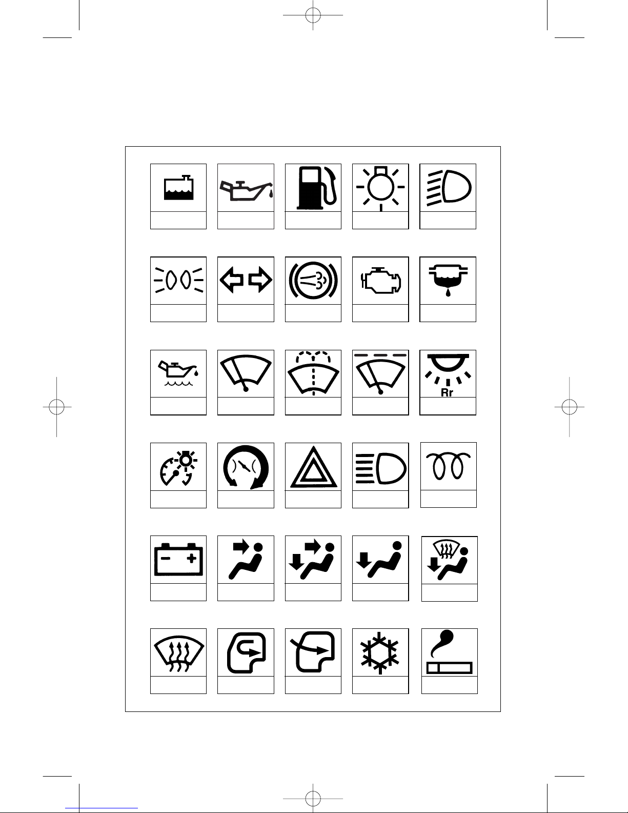
GRAPHIC SYMBOLS
Some of the following symbols are used to identify controls and
displays on your vehicle.
ENGINE
COOLANT
ENGINE OIL
PRESSURE
FUEL
MASTER LIGHTING
SWITCH
LIGHTS
PARKING TURN SIGNALS
EXHAUST
BRAKE
WINDSHIELD
WIPER
WINDSHIELD
WASHER
BODY INTERIOR
LIGHT SWITCH
ILLUMINATION
CONTROL
IDLE SPEED
CONTROL
HAZARD WARNING
FLASHER
HIGH BEAM
GLOW PLUG
BATTERY CHARGING
CONDITION
FACE BI-LEVEL FOOT
FOOT AND
DEFROSTER
WINDSHIELD
DEFROSTER
AIR
RECIRCULATION
FRESH AIR
CHECK ENGINE
WATER
SEPARATOR
ENGINE OIL LEVEL
INTERMITTENT
WIPER
AIR
CONDITIONING
LIGHTER
55702_Sec00_'08 08.2.12 9:41 AM Page 2

0-3
DAYTIME
RUNNING LIGHT
INDICATOR/BRAKE SYSTEM
WARNING LIGHT
PTO
(IF EQUIPPED)
MILES CHECK
CRUISE MAIN CRUISE SET
SERVICE VEHICLE
SOON LIGHT
CRUISE CONTROL
RESUME/
ACCEL
CRUISE CONTROL
SET/
COAST
HORN
PARKING BRAKE
INDICATOR/BRAKE SYSTEM
WARNING LIGHT
DPF
OVERDRIVE
BRAKE
LOW VACUUM
ANTI-LOCK
BRAKE SYSTEM
CHECK TRANS
ENGINE
SHUT DOWN
AUTOMATIC
TRANSMISSION
FLUID TEMPERATURE
ENGINE
OVERHEAT
BRAKE
BRAKE
BOOSTER
BRAKE
LOW VACUUM
55702_Sec00_'08 08.2.12 9:41 AM Page 3
Maximum GVWR
Front GAWR Capacity Rear GAWR Capacity
lbs (kg) lbs (kg) lbs (kg)
NPR 12,000 (5,443) 5,360 (2,431) 8,840 (4,010)
0-4
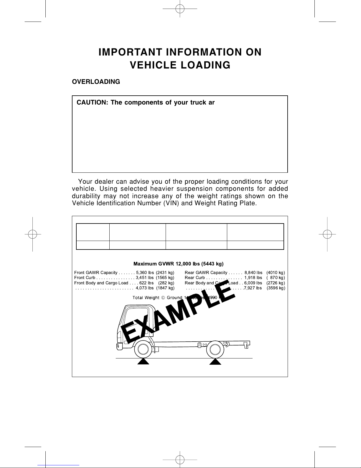
Maximum GVWR 12,000 lbs (5443 kg)
Front GAWR Capacity.......5,360 lbs(2431 kg)
Front Curb................3,451 lbs(1565 kg)
Front Body and Cargo Load....622lbs (282 kg)
........................ 4,073 lbs (1847 kg)
Rear GAWR Capacity...... 8,840 lbs (4010 kg)
Rear Curb............... 1,918 lbs( 870 kg)
Rear Body and Cargo Load . . 6,009 lbs (2726 kg)
........................7,927 lbs (3596 kg)
IMPORTANT INFORMATION ON
VEHICLE LOADING
OVERLOADING
Your dealer can advise you of the proper loading conditions for your
vehicle. Using selected heavier suspension components for added
durability may not increase any of the weight ratings shown on the
Vehicle Identification Number (VIN) and Weight Rating Plate.
CAUTION: The components of your truck are designed to provide
satisfactory service if the vehicle is not loaded in excess of either
the gross vehicle weight rating (GVWR) or the maximum front and
rear gross axle weight ratings (GAWRs). These ratings are listed
on the Vehicle Identification Number (VIN) plate, which is located
on the left side rear pillar panel below the striker.
Overloading can result in loss of vehicle control and personal
injury, either by causing component failures or by affecting vehicle
handling. It can also shorten the service life of your vehicle.
55702_Sec00_'08 08.2.12 9:41 AM Page 4

0-5
MAXIMUM FRONT AND REAR AXLE WEIGHTS
The weight of the cargo load must be properly distributed over both
the front and rear axles. The VIN and Weight Rating Plate show the
maximum weight that the front axle can carry (front GAWR). It also
shows the maximum weight that the rear axle can carry (rear GAWR).
The GVWR is the maximum permissible loaded weight of the vehicle
and takes into account the capabilities of the engine, transmission,
frame, springs, brakes, axles and tires. Actual loads at the front and
the rear axles can only be determined by weighing the vehicle. This
can be done at highway weigh stations or other such places. See your
dealer for help. The cargo load should be distributed on both sides of
the center line as equally as possible.
EFFECT ON WARRANTY
Your new vehicle limited warranty does not cover any part or
component of your vehicle which has been subject to misuse or abuse.
Any part or component which malfunctions because of overloading will
be deemed to have been subject to misuse and/or abuse.
55702_Sec00_'08 08.2.12 9:41 AM Page 5
0-6
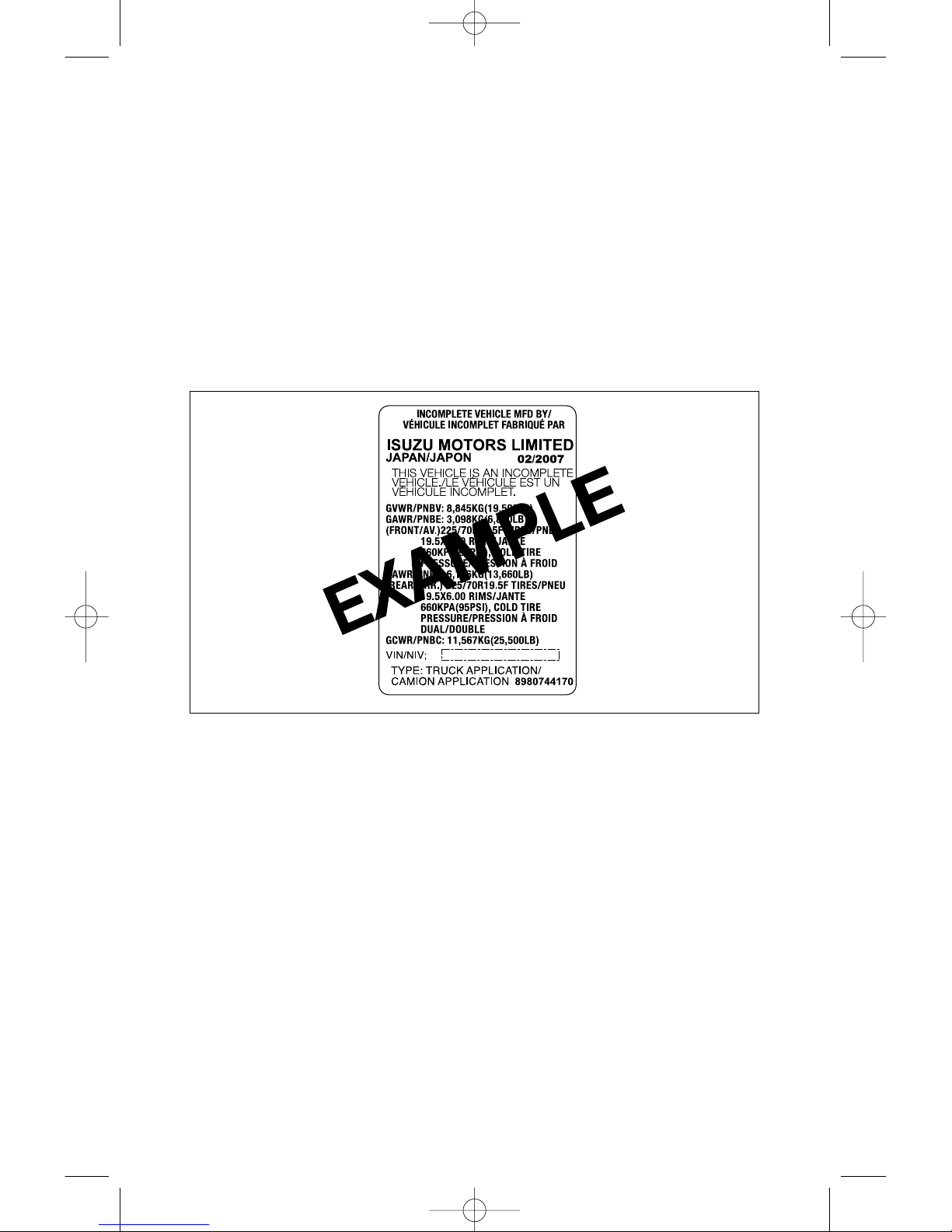
Your VIN and Weight Rating Plate will specify the following:
TIRES
The tires on your truck must be of the proper size and properly
inflated for the load that you are carrying. The VIN and Weight Rating
Plate shows the originally equipped tire size and recommended
inflation pressures.
The tire inflation tables in Section 6 show the load limits for various
size tires at various inflation pressures.
VEHICLE IDENTIFICATION NUMBER
(VIN) AND WEIGHT RATING PLATE
Your VIN and Weight Rating Plate shows the GVWR (Gross Vehicle
Weight Rating) and the front and rear GAWRs for your vehicle.
Gross Vehicle Weight (GVW) is the weight of the originally equipped
vehicle and all items added to it after it has left the factory. This would
include bodies, liftgates, refrigeration systems, etc., winches, booms,
etc., the driver and all occupants, and the load the vehicle is carrying.
The GVW must not exceed the GVWR. Also, gross weight on each of
the front and rear axles must not exceed the front and rear GAWRs
respectively.
55702_Sec00_'08 08.2.12 9:41 AM Page 6

0-7
MODEL REFERENCE
The model covered in this manual is NPR.
Single cab model
NPR
MODEL
55702_Sec00_'08 08.2.12 9:41 AM Page 7

0-8
VIN INTERPRETATION
J 1L B 4 1 6 8 7 0 0 0 0 0A W
GVWR and
Brake System
Chassis
Type Code
Check
Digit
Plant
Code
Sequential Numbers
Series
Code
Engine
Code
Model
Year Code
Identifiers
Cab
Type Code
2008
Code Description
JAL ISUZU
Code Description
1 4 x 2
Code Plant Location
7 Fujisawa
Code Description Cab Type
W
Code Series
4 NPR
Code Description
B 10001-14000 lbs.
Hydraulic Brake System
Code Description
6 Isuzu 4HK1-TC
: Bumper to Back of Cab
Steel Tilt Single Cab 71 inch BBC
55702_Sec00_'08 08.2.12 9:41 AM Page 8
1-1
SECTION 1
BEFORE DRIVING YOUR VEHICLE
DRIVER DAILY CHECKLIST
Be sure you know how to use your truck and its equipment before
operating it.
BEFORE ENTERING THE TRUCK
1. See that windows, mirrors, lights and reflectors are undamaged,
clean and unobstructed.
2. Check tires for damage and proper air pressure. Check that all
wheel nuts are in place.
3. Look for fluid leaks.
4. Be sure that the tilt cab is securely locked in the lowered position.
5. Inspect the exhaust system, checking that the tailpipe is clear.
START-UP
1. Check that all warning lights work (and that the brake alarm
buzzer works as described under that topic in this manual) when
the key is turned to “ON”, and hold until the glow plug indicator
light goes off, then “START”. The “BRAKE” system warning light
should stay on when the parking brake is applied.
2. Check all gauges (including the fuel gauge) and indicator lights.
3. Adjust the seat.
4. Be sure that the adjustable steering column is in the locked
position.
5. Check and adjust mirrors.
FINAL WALK-AROUND CHECK
Set the parking brake.
1. Look for leaks, now that the engine is running.
2. Check that all lights work.
3. Check that doors and covers are in place; and any emergency
equipment is complete.
4. Be sure everything is properly stowed.
5. Check the area under the truck, and behind it if you are about to
back up.
BEFORE DRIVING OFF
Do not drive the truck until the engine has had sufficient time to
circulate the lubricant oil. This usually requires 30 sec. to 2 minutes
depending on ambient conditions.
NOTICE: This will help reduce white start-up smoke.
55702_Sec01_'08 08.2.12 9:43 AM Page 1

1-2
1. Lock all doors.
2. Always properly fasten your seat belt. Check that the seat belt for
any other occupant is fastened properly. Never let anyone ride any
place in or on this vehicle where there is no lap belt or lapshoulder belt.
3. Push down on the brake pedal, release the parking brake, and
check that the “BRAKE” system warning light goes out. If the light
stays on, the vehicle should not be driven until the condition is
corrected.
These checks are in addition to, not instead of, the Bureau of Motor
Carrier Safety requirements. See related topics under “Maintenance
Schedule” in Section 5, especially if problems are found.
One key can operate all the locks on the vehicle. Keep one of the
two keys provided as a spare. The key code is stamped on the tag.
For vehicle security:
• Record the key code numbers.
• Keep the key code plate in a safe place (such as your wallet), NOT
IN THE VEHICLE.
• Be sure to include the key code plate when the vehicle is transferred.
If the original keys are lost, duplicates can be made using the key
codes stamped on key code plate. Contact any authorized Isuzu dealer
or a locksmith.
KEY
Main key
Spare key
Key code plate
55702_Sec01_'08 08.2.12 9:43 AM Page 2
1-3
CAB DOOR LOCKS
ALWAYS LOCK THE DOORS
To lock the cab, Iock one door from the inside by turning the button
forward on the door interior lock button.
Lock the other door from the outside following the instructions under
“DOOR LOCKS” below. Or if desired, turn the interior lock button
forward, then close the door while lifting up on the outside handle.
Overriding door locks are a standard safety feature. When the doors
are locked, the inside handles will not open them. This is to prevent
accidental opening of the doors.
OUTSIDE DOOR HANDLES
A handle for opening each cab door from outside the cab is located
at the rear edge of the door’s outer panel. To open the door from
outside the vehicle, pull up on the handle.
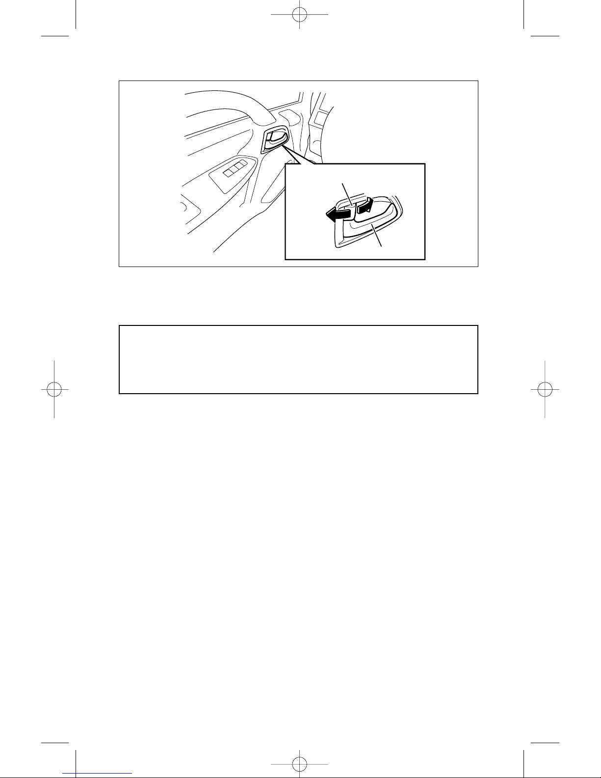
INSIDE DOOR HANDLES
An inside handle for opening each cab door is located in the
recessed area at the front of the door. To open the door, pull on the
handle. If the door is locked, the lock mechanism overrides operation
of the door handle. The door must first be unlocked before the handle
can be used to open the door.
Lock Button
Locked
Inside Handle
Unlocked
CAUTION: To help reduce the risk of personal injury in an
accident, always lock the doors when driving. Along with using the
seat belts properly, Iocking the doors helps prevent people from
being thrown from the vehicle. It also helps prevent unintended
opening of the doors and helps keep out intruders.
55702_Sec01_'08 08.2.12 9:43 AM Page 3

1-4
POWER DOOR LOCKS (IF EQUIPPED)
DOOR LOCK SWITCH
Both doors can be locked and unlocked by pressing the rocker lock
switch. Refer to Page 2-56 for switch location.
DOOR LOCKS
• A door may be locked from outside of the vehicle, by inserting the
key into the door lock and turning it counterclockwise for the driver’s
door and clockwise for the passenger’s door.
• Locking the driver’s door will lock both driver’s and passenger’s
doors.
• To unlock the door, turn the key in the opposite direction.
LOCK
UNLOCK
UPPER SIDE
LOCK
FRONT
UNLOCK
55702_Sec01_'08 08.2.12 9:43 AM Page 4

1-5
LOCK BUTTON
• There is a lock button on each door. When the lock button on the
driver’s door is turned to “Locked”, it works for both the driver’s and
passenger’s doors. Otherwise it works only for its own door.
• Turn the button forward to lock the door, and turn it rearward to
unlock the door.
To lock the door automatically when it closes -
1. Turn the button forward (the door must be opened).
2. Pull up on the outside door handle.
3. While holding the outside door handle up, close the door.
WINDOW CONTROLS
WINDOW REGULATOR HANDLE (Manual window model)
Turn the window regulator handle to raise and lower the window.
POWER WINDOWS (IF EQUIPPED)
POWER WINDOW SWITCH (DRIVER’S DOOR)
The power window switch on the driver’s door can operate both
driver’s and passenger’s power windows.
For driver’s power window
Press lightly on the switch to lower the window. The window
continues its downward motion until the switch is released (or the
window is fully opened).
Press firmly on the switch (until a click is heard) to lower the window
automatically. (To stop window movement, pull up on the switch.)
Pull up on the switch to close the window. The window continues its
upward motion until the switch is released (or the window is fully
closed).
Lock Button
Locked
Inside Handle
Unlocked
NOTICE: The engine control switch must be in the “ON” position.
55702_Sec01_'08 08.2.12 9:43 AM Page 5

1-6
POWER WINDOW SWITCH (PASSENGER’S DOOR)
The power window switch on the passenger’s door can raise and
lower the passenger’s side window only.
Press lightly on the switch to lower the window. The window
continues its downward motion until the switch is released (or the
window is fully opened).
Pull up on the switch to close the window. The window continues its
upward motion until the switch is released (or the window is fully
closed).
OPENCLOSE
OPENCLOSE
Passenger
side
Passenger
side
Driver
side
Driver
side
NOTICE: The engine control switch must be in the “ON” position.
55702_Sec01_'08 08.2.12 9:43 AM Page 6

1-7
MIRRORS
OUTSIDE REARVIEW MIRRORS
Adjust the outside rearview mirrors by hand before vehicle operation.
This helps you determine the location of objects seen in the mirror.
SUN VISORS
The sun visors may be swung down to prevent glare from the front.
They may also be swung to the side.
CAUTION: Do not adjust the outside mirrors while operating the
vehicle.
55702_Sec01_'08 08.2.12 9:43 AM Page 7

1-8
Seatback
Tilt Lever
CAUTION: Do not adjust the driver’s seat while the vehicle is
moving. The seat could move or jerk and cause a loss of control.
After adjustment, push the seat back and forth to be sure it is locked.
Take the vehicle to your dealer for servicing if the seat does not lock.
FORE-AND-AFT
The driver’s seat has a fore-and-aft adjustment and a seatback tilt
adjustment.
The fore-and-aft adjustment lever is located in front of the seat at the
base of the cushion. Move the lever to the upside, adjust the seat
position, and release the lever. The seat is designed to lock in position
when the lever is released. After adjustment, push the seat back and
forth to be sure it is locked. Take the vehicle to your dealer for
servicing if your seat does not lock.
DRIVER’S SEAT CONTROLS
ADJUST DRIVER’S SEAT WHILE PARKED
Fore-and-Aft Lever
55702_Sec01_'08 08.2.12 9:43 AM Page 8

1-9
SEATBACK LATCH (DRIVER)
The seatback latch of the driver seat is designed to limit forward
movement of the seatback during a sudden slowing of the vehicle. Tilt
the seatback to gain access to the area behind it.
The seatback latch release lever is located at the outboard side of
the seat at the base of the cushion. Raise the lever, adjust the
seatback, and release the lever.
After adjusting the seatback, push it back and forth to be sure it is
locked. Take the vehicle to your dealer for servicing if your seatback
does not lock.
Seatback Position When Moving
CAUTION: To reduce the risk of sliding under the lap belt during a
collision, an occupied reclining seat should not be reclined any
more than needed for comfort. The seatback and seat belts provide
best restraint only when the rider is sitting well back and straight
up in the seat. (The lap belt is designed to spread the force of a
collision over the hipbone. If you are reclined, the lap belt may slide
past your hips and apply restraint forces directly to the abdomen.
Therefore, in the event of a collision, the risk of personal injury will
increase with increasing recline of the seatback.)
Do not adjust the reclining seatback on the driver’s seat while the
vehicle is moving. The seatback could jerk and cause a loss of control.
55702_Sec01_'08 08.2.12 9:43 AM Page 9
1-10
SEAT BELT SYSTEMS
NEVER:
• Put the lap portion of a seat belt over any armrest.
• Wear a shoulder belt under your arm nearest the door.
• Use a belt for more than one person at a time.
• Wear the belts twisted or with a buckle release button facing
downward or inward.
• Let the belt system become damaged by the door or seat.
• Put anything into the opening where the seat belt passes through the
trim panel. (This may jam the retractor or damage the belt.)
Twisted Belt
Do not let the belt twist while it is rewinding: it may cause the
retractor to jam so it will not rewind further. If it is not fully rewound,
the belt cannot be pulled out. Should the belt jam, you may be able to
release it by working the belt in and out until the belt rewinds far
enough to unlock. However, if the belt remains jammed or other parts
of the restraint system do not work properly, have your dealer service
it.
CAUTION: To help reduce the risk of personal injury in collisions or
sudden maneuvers, use the seat belts following these instructions
on their proper use, maintenance, and use with child restraint
systems. This applies to pregnant women. Pregnant women should
use a lap-shoulder belt whenever possible; the lap portion should
continue to be worn low and snug throughout the pregnancy.
Children small enough for child restraints (as indicated on the
label of such restraints), including booster seats, should always be
transported in them.
Children who have outgrown child restraint systems should use
the vehicle’s seat belts.
55702_Sec01_'08 08.2.12 9:43 AM Page 10
1-11
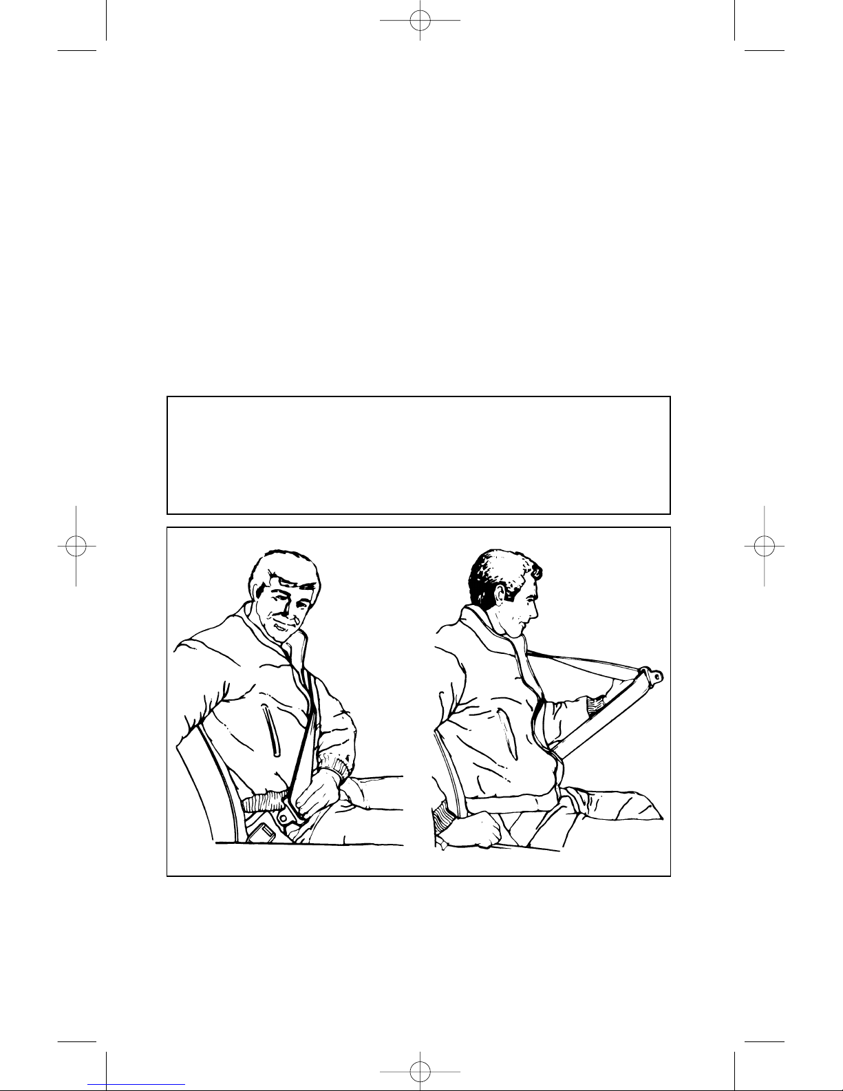
LAP-SHOULDER BELT
1. Adjust the driver’s seat as needed and sit well back and straight up.
(The passenger seat does not adjust.) Grasp the latch plate and:
• Pull the belt as far as it will reach across your lap.
• Hold the latch plate at an angle to the webbing and slide it
further (toward the front of the truck).
• Then pull it slowly across your lap and push it into the buckle
until it clicks. If the retractor locks before the latch plate reaches
the buckle, let the belt retract slightly, then withdraw it slower
than before.
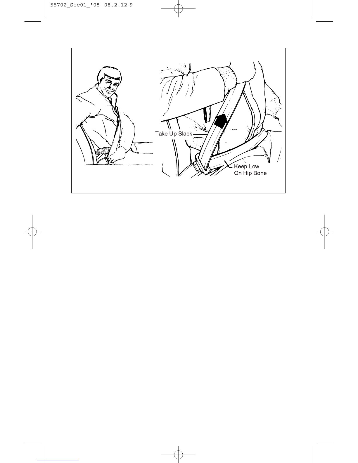
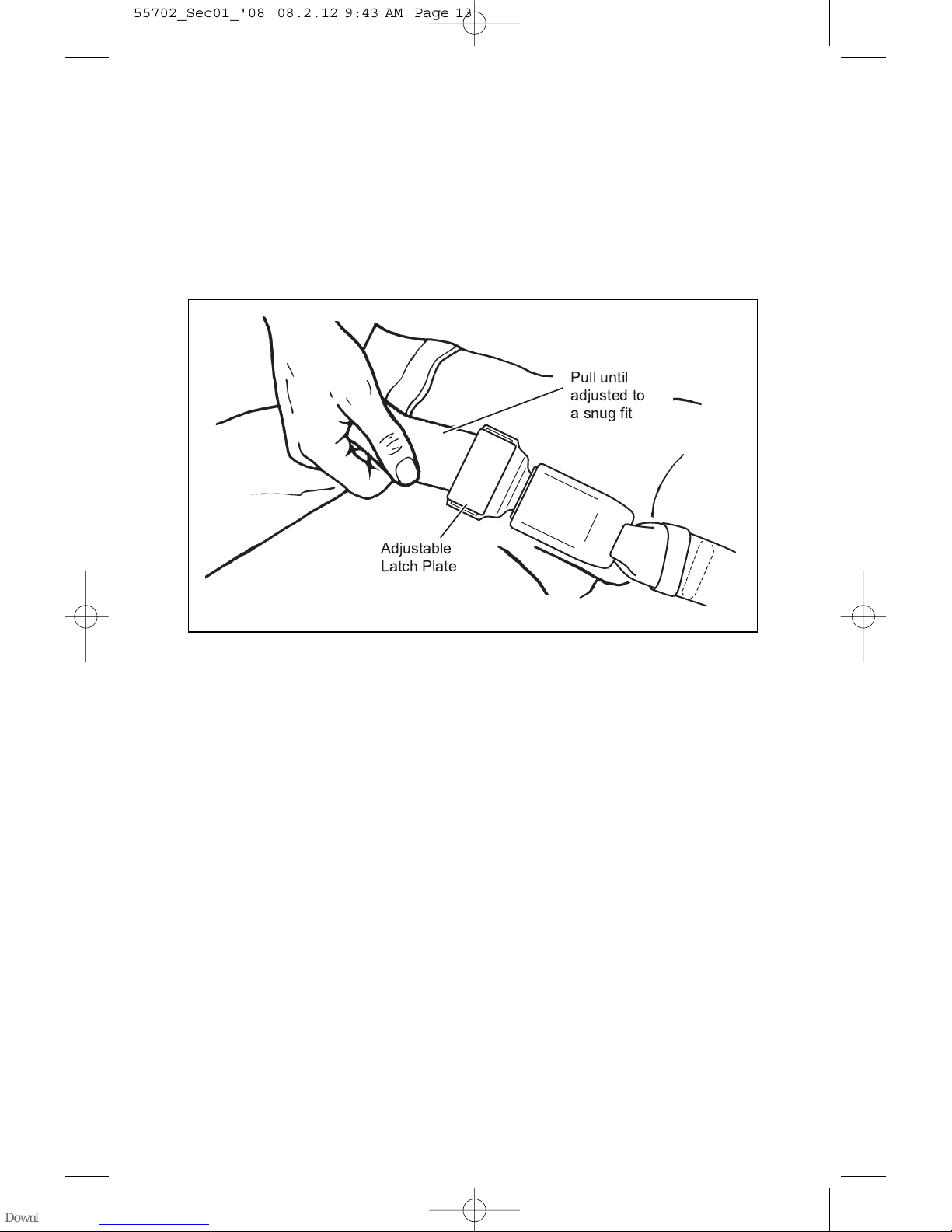
2. To reduce the risk of sliding under the belt during a collision,
position the belt across your lap as low on your hips as possible
and adjust it to a snug fit by pulling the “shoulder” portion upward
through the latch plate.
The lap-shoulder belt is designed to lock during a sudden stop or
impact. At other times it should move freely.
CAUTION: To help reduce the risk of personal injury or death in an
accident, if a child is using the vehicle’s seat belts because the
child has outgrown child restraints, including booster seats, and if
the shoulder belt is on or very close to the child’s face or neck,
move the child toward the center of the seat, away from the
shoulder belts.
W-01623
55702_Sec01_'08 08.2.12 9:43 AM Page 11
1-12
3. To unfasten the belt, push the button on the buckle. The belt
should retract when the buckle is unlatched, but hold the latch
plate while the belt is retracting, to keep it from hitting people or
nearby objects. To help prevent damage to the seat belt and
interior trim before closing the door, be sure the belt is fully
retracted and the latch plate is out of the way.
Take Up Slack
Keep Low
On Hip Bone
55702_Sec01_'08 08.2.12 9:43 AM Page 12
1-13
CENTER LAP BELT
1 . The center seat lap belt has no retractor, but should be positioned,
worn and released as described above. The belt is adjusted to
snug fit by pulling on the free end of the webbing coming from the
latch plate.
2. To lengthen the center seat lap belt, place the latch plate at an
angle to the belt webbing and pull on the latch plate; the belt
should then slide easily through the latch plate adjustment feature.
SEAT BELT INSPECTION
Now and then check that the belts, buckles, latch plates, retractors,
anchorages and guide loops work properly; look for loose parts or
damage (without disassembly) that could keep the restraint system
from doing its job. Have a belt assembly replaced if the webbing has
been cut or otherwise damaged. Replace belts, retractors, and
hardware used in all but a minor collision. Also, restraint systems
should be replaced and anchorages properly repaired if they were in
areas damaged by a collision, whether the belt was in use or not. If
there is any question, replace the belt system. Damage, whether
visible or not, could result in a serious personal injury in the event of
an accident.
Pull until
adjusted to
a snug fit
Adjustable
Latch Plate
55702_Sec01_'08 08.2.12 9:43 AM Page 13

1-14
CHILD RESTRAINT
Be sure to follow all installation and use instructions that come with
any child restraint system.
Child restraint systems are designed to be secured in vehicle seats
either by the lap belt, or the lap portion of the lap-shoulder belt at that
seating position. The child must also be secured within the restraint by
the means provided by the child restraint manufacturer. If the child or
the child restraint is not properly secured, the child risks personal
injury in the event of a collision.
Using a Lap Belt That Has No Retractor
When securing a child restraint with the center seat lap belt, pull the
excess webbing through the belt’s adjustment feature, then take these
steps:
• Once installed, push and pull the child restraint in all directions to be
sure it is secure. If it comes loose, flip the end of the belt with the
adjustment feature over before rebuckling.
• If the child restraint is still not secure, use the outboard seating
position in the vehicle and contact your dealer and the child restraint
manufacturer for help.
• Secure the child in the restraint in accordance with the child restraint
manufacturer’s instructions.
CAUTION: Children small enough for child restraints (as indicated
on the label of such restraints), including booster seats, should
always be transported in them. Children who have outgrown child
restraint systems should wear seat belts. The lap belt should be
snug and positioned low on the abdomen so that it is below the
top of the hipbone. Otherwise, the belt could intrude into the
child’s abdomen during an accident and cause personal injury.
When a child has grown enough so that the shoulder belt can be
worn, a seating position with a shoulder belt should be chosen
whenever possible. If the shoulder belt is on or very close to the
child’s face or neck, move the child toward the center of the seat,
away from the shoulder belt.
Any unrestrained child could be injured by striking the vehicle’s
interior or by ejection from the vehicle during an accident or
driving maneuver. Never allow a child to be held by another
occupant instead of being properly restrained. If not properly
restrained, the child could strike the vehicle interior or be crushed
by the person holding the child, or by other occupants.
55702_Sec01_'08 08.2.12 9:43 AM Page 14
1-15
Installation on Outboard Seat
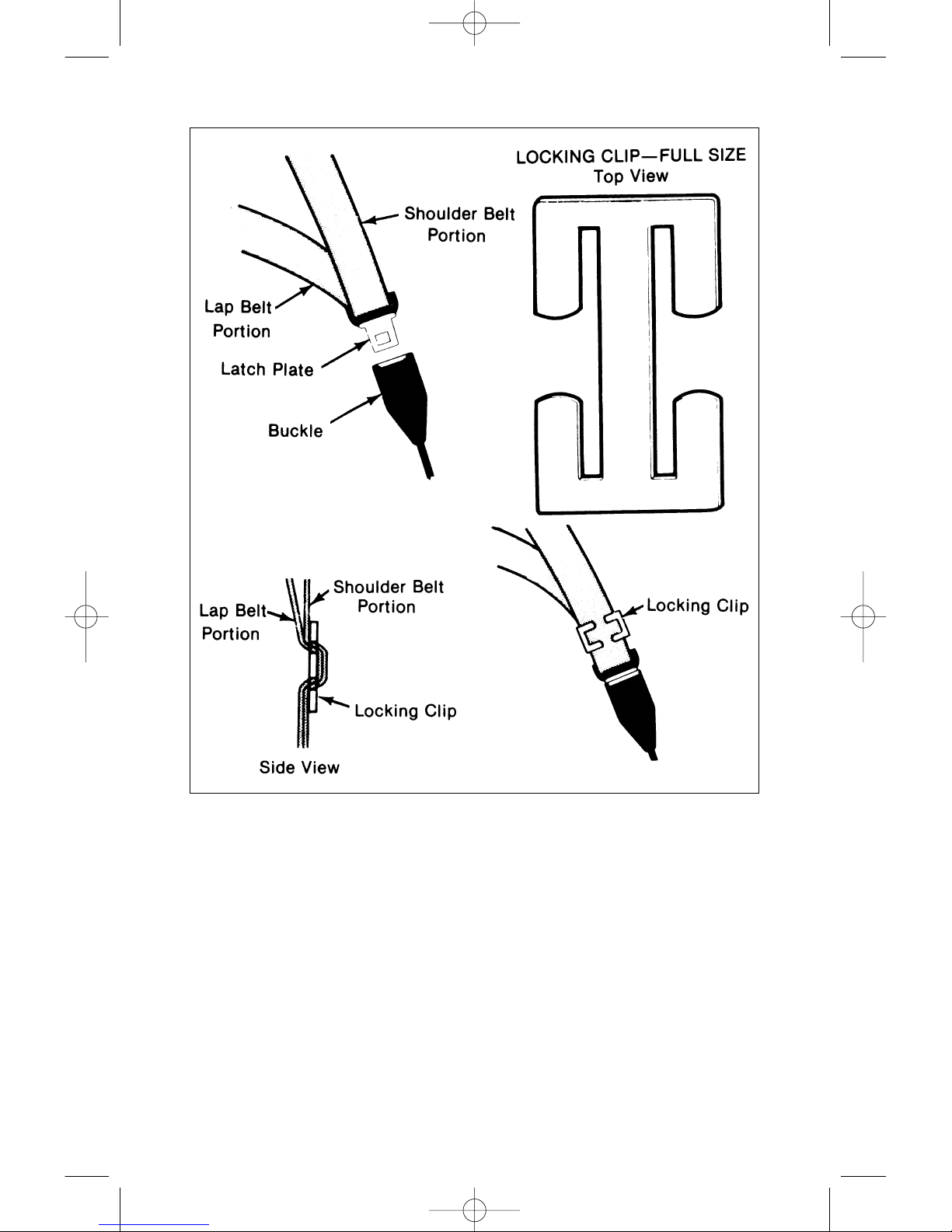
A seat belt locking clip is required for installation of a child restraint
system on the outboard seat of this vehicle. A locking clip may usually
be obtained where child restraints are sold, or by contacting your
dealer for assistance. Make sure the locking clip is identical to the one
shown on page 1-16. Until you have the clip, use the child restraint
system only in the center seat.
CAUTION: To help avoid personal injury or death during a collision
or sudden maneuver, always thread both the lap and shoulder belt
through the locking clip when securing a child restraint on the
outboard seat. If the clip is not used or installed properly, the child
restraint may move or tip over when your vehicle turns or stops
abruptly.
Secure the child restraint with the lap belt portion of the seat belt in
accordance with the restraint manufacturer’s instructions. Then thread
both the lap and shoulder belt portions through the locking clip. Push
and pull the child restraint in all directions to be sure it is secure.
When your child restraint is not installed, remove the locking clip to
permit normal use of the lap-shoulder belt. Keep the locking clip in the
glove box to help prevent its loss.
Child Restraint With Top Strap
CAUTION: We do not recommend using a child restraint that
requires the use of a top strap. There is no appropriate place to
attach a top strap anchor behind the seat in this vehicle.
55702_Sec01_'08 08.2.12 9:43 AM Page 15
1-16
W-01621
SEAT BELT EXTENDER
If the vehicle’s seat belt will fasten around you, you should use it.
But if a seat belt isn’t long enough to fasten, your dealer will order you
an extender. When you go in to order it, take the heaviest coat you will
wear, so the extender will be long enough for you. The extender will be
just for you, and just for the seat in your vehicle that you choose. Do
not let someone else use it, and use it only for the seat it is made to fit.
To wear it, just attach it to the regular seat belt.
55702_Sec01_'08 08.2.12 9:43 AM Page 16

1-17
DIESEL PARTICULATE FILTER (DPF)
The DPF is the system which traps Particulate Matter (PM) in
exhaust gas. This collects PM into the DPF and regenerates the filter
(burns PM) automatically. To prevent DPF failure, take the following
precautions.
CAUTION:
• Exhaust gas from the DPF, muffler, exhaust pipe and tailpipe is
extremely hot when the engine is running, during regeneration
(burning), or immediately after driving.
Nearby flammable materials such as dried grass and wastepaper
may catch fire.
Be very careful not to touch them by accident. You may get
burned.
When you service the vehicle, stop the engine to prevent burns.
• Always use diesel fuel. Use of low quality fuel may adversely
affect the engine parts, and cause failure.
• Use of other than specified fuel may adversely affect the engine
or emission control system and cause failure. Especially for
common rail type engines, always use ultra low sulfur diesel fuel
(15 ppm or less of sulfur content).
• If other than specified diesel fuel is used on a vehicle with DPF,
the vehicle may not conform to specifications.
• Do not modify the DPF or exhaust pipe.
Modification of the direction, length or diameter of the exhaust
pipe will adversely affect the exhaust gas purification system. If
modification is needed according to equipment type, contact
your Isuzu dealer.
55702_Sec01_'08 08.2.12 9:43 AM Page 17
1-18
NOTICE:
• For engine oil, use low ash engine oil. Use of others than those
designated by Isuzu that support the DPF may shorten the
cleaning intervals of the DPF and may lower fuel efficiency.
• The DPF automatically regenerates when a certain amount of PM
(Particulate Matter) accumulates in the filter. However, this may
not complete depending on driving conditions. In this situation,
the DPF indicator (amber) will come on. Perform manual
regeneration according to the procedure. This is not a system
failure, but is to restore the DPF function.
• The exhaust brake valve is activated while the vehicle is idling in
the DPF regeneration (burning) mode. Sound occurs when the
exhaust brake valve is activated and deactivated. This is not a
failure.
• A small amount of white smoke may be emitted from the exhaust
pipe with Particulate Matter (PM) burned during DPF
regeneration. This is not a failure. Also, do not perform the
emergency regeneration indoors with poor ventilation.
• White smoke may be emitted during the DPF regeneration after
the new vehicle runs for a certain distance.
This is not a failure. White smoke may not necessarily be emitted
when the vehicle is new.
• Because of the exhaust gas purification system, the gas from the
exhaust pipe smells differently from that of conventional diesel
vehicles.
• With long continuous idling, the exhaust brake valve may be
activated to prevent white smoke after a certain period of time.
• Use of low ash oil lengthens the maintenance interval of the DPF.
55702_Sec01_'08 08.2.12 9:43 AM Page 18

1-19
CAUTION: In a place with poor ventilation, carbon monoxide
poisoning may occur. Starting or warming-up the engine should be
performed in a well-ventilated place. White smoke may be
temporarily emitted due to PM combustion during the DPF manual
regeneration. Do not perform DPF manual regeneration indoors
with poor ventilation.
CAUTION:
• Before starting the engine, make sure that there are no
flammable materials around the vehicle and dried grass does not
wind around the exhaust pipe. Be careful that the hot exhaust
pipe and hot exhaust gas does not catch fire after engine racing,
or engine running at high speed for long periods of time.
• Pay close attention to the heat of the exhaust gas during idling
especially when using the PTO (POWER TAKE-OFF) or
afterburning on the vehicle equipped with the DPF.
CAUTION: Always use diesel fuel.
Use of low quality fuel may adversely affect the engine parts, and
cause failure.
Use of other than specified fuel may adversely affect the engine
or emission control system and cause failure. Especially for the
common rail type engine, always use ultra low sulfur diesel fuel (15
ppm or less of sulfur content).
If other than specified diesel fuel is used on the vehicle with the
DPF, the vehicle may not conform to specifications.
BEFORE DRIVING
Use the specified fuel (ultra low sulfur diesel fuel only)
Do not keep the engine running indoors
Be careful with flammable materials
55702_Sec01_'08 08.2.12 9:43 AM Page 19

2-1
SECTION 2
STARTING AND OPERATING
Engine Exhaust Gas Caution
(Carbon Monoxide)
CAUTION: Do not breathe exhaust gas because it contains carbon
monoxide, which by itself has no color or odor. Carbon monoxide is
a dangerous gas. It can cause unconsciousness and can be lethal.
If at any time you think exhaust fumes are entering the cab, have
the cause determined and corrected as soon as possible. If you must
drive under these conditions, drive only with all windows fully open.
Prevent carbon monoxide from entering the cab. The best way is
to keep the engine exhaust system, cab and cab ventilation system
properly maintained.
We recommend that the exhaust system and cab be inspected by
a competent technician:
•
Each time the vehicle has an oil change.
•
Whenever a change is noticed in the sound of the exhaust system.
•
Whenever the exhaust system, underbody or cab is damaged or
becomes corroded.
See “Maintenance Schedule” in Section 5 of this manual for parts
requiring inspection.
To allow proper operation of your vehicle’s ventilation system, keep
the air inlet grille clear of snow, leaves or other obstructions at all times.
Do not park with the engine running or idle this vehicle for more than
10 minutes with the ventilation system control switch in the “OFF”
position. Even with the ventilation system on, running the engine while
parked or stopped for longer periods of time is not recommended. Entry
of carbon monoxide into the cab is possible with a poorly repaired,
damaged, or corroded exhaust system or cab.
Do not run the engine in confined areas (such as garages or next to a
building) any more than needed to move the vehicle. When the vehicle
has to be stopped in an unconfined area with the engine running for any
more than a few minutes, take the following steps:
A. Adjust the heating or cooling system to force outside air into
the cab. With temperature and select levers in any position:
•
Set the air source lever to the fresh air position.
•
Set the fan blower to the “3” or “4” position.
•
See “Heating and Ventilation System Controls” later in this
section of the manual.
B. Keep the exhaust tailpipe area clear of snow and other material
to help reduce the buildup of exhaust gases under the vehicle.
This is particularly important when parked in blizzard conditions.
55702_Sec02-1_'08 08.2.12 9:45 AM Page 1

2-2
NEW VEHICLE BREAK-IN
Good vehicle care begins with proper break-in. While every new
vehicle goes through rigid factory and dealer inspection and tests
before delivery, the care you give your vehicle during the initial breakin period can pay off in longer life, better performance and more
economical operation. Follow the recommendations listed below:
•
Warm up the engine by driving easily for the first few minutes before
placing it under load.
•
Keep speeds below 50 MPH (80 km/h) for the first 500 miles (800
kilometers).
•
Do not drive for extended periods at any one constant speed, either
fast or slow, during the first 500 miles (800 kilometers).
•
Use the lowest gear ratio available when starting a loaded vehicle
and when climbing slopes to avoid lugging the engine.
•
Use the correct gear to maintain the desired road speed without
lugging the engine.
•
Avoid racing the engine, full-throttle starts and aggressive application
of brakes when stopping.
•
Keep tires properly inflated for the load carried.
•
Check lubricant levels in the engine and transmission frequently (at
least weekly).
MECHANICAL DRIVESHAFT BRAKE
BURNISH PROCEDURE
It is recommended that the driveshaft mounted parking brake be
burnished as part of the new vehicle break-in procedure. Increased
parking brake performance will result when the parking brake is
burnished according as specified below:
•
Make 10 moderate stops, using the hand brake, from 10 MPH (16
km/h) while spacing the stops a minimum of 2.5 miles (4 km) apart.
•
Operate the vehicle at 20 MPH (32 km/h) between stops.
55702_Sec02-1_'08 08.2.12 9:45 AM Page 2
 Loading...