

Page 1

TNV_OperationManual_T4(under 19kW).book Page i Wednesday, June 17, 2015 11:23 AM
TNV Operation Manual
INTRODUCTION
To help you enjoy your Isuzu C series engine for
many years to come, please follow these
recommendations:
• Read and understand this Operation Manual
before you operate the machine to ensure that
you follow safe operating practices and
maintenance procedures.
• Keep this Operation Manual in a con venient plac e
for easy access.
• If this Operation Manual is lost or damaged, order
a new one from your Isuzu Distributor.
• Make sure this manual is transferred to
subsequent owners. This manual should be
considered a permanent part of the engine and
remain with it.
• Constant efforts are made to improve the quality
and performance of Isuzu products, so some
details included in this Operation Manual may
differ slightly from your engine. If you have any
questions about these differences , please contact
your Isuzu Distributor.
• The specifications and components (instrument
panel, fuel tank, etc.) described in this manual
may differ from ones installed on your machine.
Please refer to the manual provided by the
manufacturer of these components.
i
Page 2

TNV_OperationManual_T4(under 19kW).book Page ii Wednesday, J une 17, 2015 11:23 AM
INTRODUCTION
RECORD OF OWNERSHIP
Take a few moments to record the information you need when you contact Isuzu for service, parts or
literature.
Engine model:________________________________________________________________________
Engine serial No.: _____________________________________________________________________
Date purchased: ______________________________________________________________________
Dealer: ______________________________________________________________________________
Dealer phone: ________________________________________________________________________
SYMBOL EXPLANATION
The following symbols are used throughout this manual to identify specific engine model information
This symbol indicates information pertaining to the following indirect injection engines:
• 3CH1-NGZG01
• 3CH1-SDZP01
• 3CJ1-NGZG01
• 3CJ1-SDZP01
All of the models conform to the engine emission regulations (EPA 2013 rules).
This symbol indicates information pertaining to the following direct injection engines:
•3CE1
This model conform to the engine emission regulations (EPA 2013 rules).
ii
Page 3

TNV_OperationManual_T4(under 19kW).book Page iii Wednesday, June 17, 2015 11:23 AM
TABLE OF
CONTENTS
Introduction............................................................................................... i
Record of Ownership........................................................................... ii
Symbol Explanation............................................................................. ii
Table of Contents ................................................................................... iii
Isuzu Engine After Service .................................................................... 1
Isuzu Genuine Parts........................................................................... 2
Emission-Related Installation Instructions (REF) ............................... 2
Installation of Nonroad Engines into Equipment........................... 2
Allowable Air Intake Restriction and Exhaust Back Pressure....... 2
Allowable Air Intake Restriction.................................................... 2
Allowable Exhaust Back Pressure................................................ 2
Safety....................................................................................................... 3
Safety Statements .............................................................................. 3
Safety Precautions.............................................................................. 4
Before You Operate...................................................................... 4
During Operation and Maintenance.............................................. 4
Product Overview................................................................................. 13
Isuzu C series Engine Features and Applications............................ 13
Component Identification.................................................................. 14
Location of Labels............................................................................. 17
Function of Major Engine Components ............................................ 18
Function of Cooling System Components ........................................ 20
Electronic Control System ................................................................ 21
Main Electronic Control Components and Features......................... 24
iii
Page 4

TNV_OperationManual_T4(under 19kW).book Page iv Wednesday, June 17, 2015 11:23 AM
TABLE OF CONTENTS
Gauges and Indicators...................................................................... 26
Gauges........................................................................................ 26
Indicators..................................................................................... 27
Gauges and Indicators of Electronic Control System........................ 28
Gauges........................................................................................ 28
Indicators..................................................................................... 28
Controls............................................................................................. 29
Key Switch................................................................................... 29
Glow Plugs.................................................................................. 30
Governor Lever ........................................................................... 30
Engine Stop Solenoid (IDI Engines)............................................ 31
Speed Control of Electronically Controlled Engines.................... 31
Electronic Engine Speed Control ................................................ 32
Before You Operate .............................................................................. 35
Diesel Fuel ........................................................................................ 36
Diesel Fuel Specifications........................................................... 36
Filling the Fuel Tank.................................................................... 41
Priming the Fuel System............................................................. 42
Engine Oil.......................................................................................... 43
Engine Oil Specifications............................................................. 43
Engine Oil Viscosity..................................................................... 44
Checking Engine Oil.................................................................... 44
Adding Engine Oil........................................................................ 44
Engine Oil Capacity (Typical)...................................................... 45
Engine Coolant.................................................................................. 46
Engine Coolant Specifications..................................................... 47
Filling Radiator with Engine Coolant ........................................... 47
Daily Check of the Cooling System............................................. 48
Engine Coolant Capacity (Typical).............................................. 48
Daily Checks ..................................................................................... 49
Visual Checks.............................................................................. 49
Check Diesel Fuel, Engine Oil and Engine Coolant Levels......... 49
Check Engine Speed Control...................................................... 49
Check Operator’s Console.......................................................... 50
Check Indicators.......................................................................... 50
Engine Operation .................................................................................. 53
Starting Engine.................................................................................. 54
Cold Start Device .............................................................................. 56
High-altitude Injection Control Device............................................... 56
Checking the Engine During Operation............................................ 57
Adjust Engine Speed......................................................................... 59
Shutting Down the Engine................................................................. 60
iv
Page 5

TNV_OperationManual_T4(under 19kW).book Page v Wednesday, June 17, 2015 11:23 AM
Periodic Maintenance........................................................................... 61
Precautions....................................................................................... 62
The Importance of Periodic Maintenance................................... 62
Performing Periodic Maintenance............................................... 62
The Importance of Daily Checks................................................. 62
Keep a Log of Engine Hours and Daily Checks.......................... 62
Isuzu Replacement Parts............................................................ 62
Tools Required ........................................................................... 62
Ask Your Isuzu Distributor For Help ........................................... 62
Required EPA/ARB Maintenance USA Only.............................. 62
EPA/ARB Installation Requirements USA Only.......................... 63
Tightening Fasteners.................................................................. 63
Standard Torque Chart..................................................................... 63
Periodic Maintenance Schedule....................................................... 64
Periodic Maintenance Chart ....................................................... 64
Periodic Maintenance Procedures.................................................... 66
After Initial 50 Hours of Operation .............................................. 66
Every 50 Hours of Operation ...................................................... 71
Every 250 Hours of Operation .................................................... 75
Every 500 Hours of Operation .................................................... 79
Every 1000 Hours of Operation .................................................. 83
Every 1500 Hours of Operation .................................................. 85
Every 2000 Hours of Operation .................................................. 86
Every 3000 Hours of Operation .................................................. 87
Troubleshooting ................................................................................... 89
Troubleshooting Chart...................................................................... 90
Troubleshooting of Electronic Control System.................................. 92
Fault Detection Capability........................................................... 92
Troubleshooting Information............................................................. 94
List of Possible Faults of Electronically Controlled Engines............. 95
Long-Term Storage .............................................................................. 99
Before You Place the Engine In Long-Term Storage ..................... 100
Returning the Engine to Service..................................................... 101
Specifications ..................................................................................... 103
Engine General Specifications........................................................ 104
Principal Engine Specifications....................................................... 105
TABLE OF CONTENTS
v
Page 6

TNV_OperationManual_T4(under 19kW).book Page vi Wednesday, June 17, 2015 11:23 AM
TABLE OF CONTENTS
This Page Intentionally Left Blank
vi
Page 7

TNV_OperationManual_T4(under 19kW).book Page 1 Wednesday, June 17, 2015 11:23 AM
TNV Operation Manual
ISUZU ENGINE
AFTER SERVICE
Please feel free to contact your Isuzu distributor for
periodical inspection and maintenance.
1
Page 8

TNV_OperationManual_T4(under 19kW).book Page 2 Wednesday, June 17, 2015 11:23 AM
ISUZU ENGINE AFTER SERVICE
ISUZU GENUINE PARTS
The Isuzu genuine parts are identical with those of used in the
engine production, and accordingly, they are warranted by Isuzu
Motors Limited.
The Isuzu genuine parts are supplied by the Isuzu distributors or
the authorized parts suppliers. Please designate "Isuzu Genuine
Parts" when you need engine parts.
EMISSION-RELATED INSTALLATION INSTRUCTIONS (REF)
Failing to follow these instructions when installing a certified engine in a piece of nonroad equipment
violates Federal Law (40 CFR1068.105(B)), subject to fines or other penalties as described in the clean air
act.
Installation of Nonroad Engines into Equipment
To ensure engines operate under the certified configurations, Isuzu has established defined application
requirements when installing any certified engine into a piece of equipment. The instructions outlined below
are included in our certification process and any failure to comply will be considered tampering.
Isuzu certifies engines to operate under variable speed or constant speed conditions. Engines certified as
constant speed are prohibited from installation into variable speed applications. The emission control
information label will identify an engine certified as constant speed.
Allowable Air Intake Restriction and Exhaust Back Pressure
Resistance to intake airflow and exhaust gas flow is generated in the intake and exhaust systems.
Exceeding the limitations will affect the operation of an engine and its certified configuration. Refer to the
installation requirements and limitations of the Isuzu C series Application Manual for the engine being
equipped with these systems.
Allowable Air Intake Restriction
Engine model
All models 2.94 (300) 6.23 (635)
Initial upper limit Upper limit for air cleaner replacement
Allowable air intake restriction kPa (mmAq)
Allowable Exhaust Back Pressure
Engine model
3CH1, 3CJ1 9.81 (1000) 11.77 (1200)
3CE1 12.75 (1300) 15.30 (1560)
Initial upper limit Upper limit for exhaust system cleaning
Allowable exhaust back p ressure kPa (mmAq)
2
Page 9

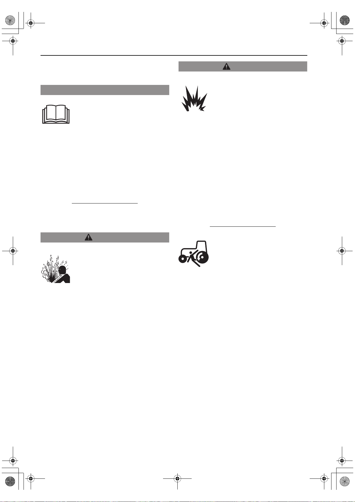
DANGER
WARNING
CAUTION
TNV_OperationManual_T4(under 19kW).book Page 3 Wednesday, June 17, 2015 11:23 AM
TNV Operation Manual
SAFETY
SAFETY STATEMENTS
Isuzu is concerned for your safety and your
machine’s condition. Safety statements are one of
the primary ways to call your attention to the
potential hazards associated with Isuzu C series
engine operation. Follow the precautions listed
throughout the manual before operation, during
operation and during periodic maintenance
procedures for your safety, the safety of others and
to protect the performance of your engine . Keep the
labels from becoming dirty or torn and replace them
if they are lost or damaged. Also, if you need to
replace a part that has a label attached to it, make
sure you order the new part and label at the same
time.
DANGER indicates a hazardous situation which,
if not avoided, will result in death or serious
injury.
WARNING indicates a hazardous situation
which, if not avoided, could result in death or
serious injury.
CAUTION indicates a hazardous situation
which, if not avoided, could result in minor or
moderate injury.
This safety alert symbol appears with
most safety statements. It means
attention, become alert, your safety is
involved! Please read and abide by the
message that follows the safety alert
symbol.
NOTICE
NOTICE indicates a situation which can cause
damage to the machine, personal property and/or
the environment or cause the equipment to operate
improperly.
3
Page 10
NOTICENOTICE
DANGER
TNV_OperationManual_T4(under 19kW).book Page 4 Wednesday, June 17, 2015 11:23 AM
SAFETY
SAFETY PRECAUTIONS
Before You Operate
• Never permit any one to operate the
engine or driven machine without
proper training.
• Read and understand this Operation Manual
before you operate or service the machine to
ensure that you follow safe operating practices
and maintenance procedures.
• Machine safety signs and labels are additional
reminders for safe operating and maintenance
techniques.
• See your Isuzu Distributor for additional training.
During Operation and Maintenance
Scald Hazard!
• Never remove the radiator cap if
the engine is hot. Steam and hot
engine coolant will spurt out and
seriously burn you. Allow the
engine to cool down before you
attempt to remove the radiator
cap.
• Tighten the radiator cap securely after you
check the radiator. Stea m can spurt out during
engine operation if the cap is loose.
• Always check the level of the engine coolant
by observing the reserve tank.
• Failure to comply will result in death or
serious injury.
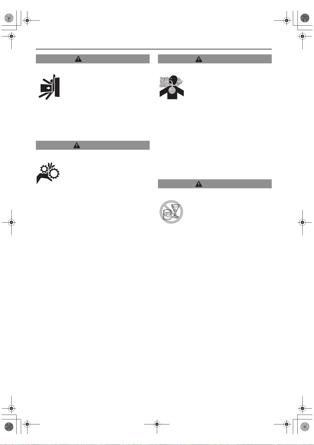
DANGER
Explosion Hazard!
• Keep the area around the battery
well-ventilated. While the engine
is running or the battery is
charging, hydrogen gas is
produced which can be easily
ignited.
• Keep sparks, open flame and any other form
of ignition away while the engine is running or
battery is charging.
• Never short out the battery terminals,
including when checking the remaining
battery charge. This will result in a spark and
may cause an explosion or fire. Use a
hydrometer to check the remaining battery
charge.
• If the electrolyte is frozen, slowly warm the
battery before you recharge it.
• Failure to comply will result in death or
serious injury.
Sudden Movement Hazard!
• Never start the engine by
shorting out the starter terminal
and the battery terminal
(Jump-start). The machine may
move suddenly if the machine
safety circuit is released, but
the gear is still engaged.
• Failure to comply will result in death or
serious injury.
4
Page 11

DANGER
(Continued)
TNV_OperationManual_T4(under 19kW).book Page 5 Wednesday, June 17, 2015 11:23 AM
DANGER
Fire and Explosion Hazard!
• Diesel fuel is extremely
flammable and explosive under
certain conditions.
• When you remove any fuel system component
to perform maintenance (such as changing
the fuel filter) place an approved container
under the opening to catch the fuel.
• Never use a shop rag to catch the fuel. Vapors
from the rag are flammable and explosive.
• Wipe up any spills immediately.
• Wear eye protection. The fuel system is under
pressure and fuel could spray out when you
remove any fuel system component.
• Only use the key switch to start the engine.
• Never jump-start the engine. Sparks caused
by shorting the battery to the starter terminals
may cause a fire or explosion.
• If the unit has an electric fuel pump, in the
case of DI engine, since air is automatically
bled, by keeping the key of the starter switch
in the ON position for 10 to 15 seconds, the
fuel system can be primed. If this is an IDI
engine, keep the key in the ON position
(within 15 seconds) until fuel without bubbles
comes out from the air bleeding bolt. Here, do
not turn the key to the START position.
• If the unit has a mechanical fuel pump, when
you prime the fuel system, operate the fuel
priming lever of the mechanical fuel pump
several times until the fuel filter cup is filled
with fuel. On top of that, operate the fuel feed
pump for several times until fuel without
bubbles comes out from the air bleeding bolt.
• Never use diesel fuel as a cleaning agent.
• Never remove the fuel cap with the engine
running.
• Only fill the fuel tank with diesel fuel. Filling
the fuel tank with gasoline may result in a fire
and will damage the engine.
• Never refuel with the engine running.
• Keep sparks, open flames or any other form of
ignition (match, cigarette, static electric
source) well away when refueling.
• Never overfill the fuel tank.
• Fill the fuel tank. Store any containers
containing fuel in a well-ventilated area, away
from any combustibles or sources of ignition.
• Be sure to place the diesel fuel container on
the ground when transferring the diesel fuel
from the pump to the container. Hold the hose
nozzle firmly against the side of the container
while filling it. This prevents static electricity
buildup which could cause sparks and ignite
fuel vapors.
• Never place diesel fuel or other flammable
material such as oil, hay or dried grass close
to the engine during engine operation or
shortly after shutdown.
• Before you operate the engine, check for fuel
leaks. Replace rubberized fuel hoses every
two years or every 2000 hours of engine
operation, whichever comes first, even if the
engine has been out of service. Rubberized
fuel lines tend to dry out and become brittle
after two years or 2000 hours of engine
operation, whichever comes first.
• When you prime the fuel system, operate the
fuel priming lever of the mechanical fuel pump
several times until the fuel filter cup is filled
with fuel.
• Failure to comply will result in death or
serious injury.
SAFETY
5
Page 12
DANGER
WARNING
TNV_OperationManual_T4(under 19kW).book Page 6 Wednesday, June 17, 2015 11:23 AM
SAFETY
Crush Hazard!
• When you need to transport an
engine for repair, have a helper
assist you to attach it to a hoist
and load it on a truck.
• Never stand under a hoisted engine. If the
hoist mechanism fails, the engine will fall on
you, causing death or serious injury.
• Failure to comply will result in death or
serious injury.
Sever Hazard!
• Keep hands and other body parts
away from moving/rotating parts
such as the cooling fan, flywheel
or PTO shaft.
• Wear tight-fitting clothing and keep your hair
short or tie it back while the engine is running.
• Remove all jewelry before you operate or
service the machine.
• Never start the engine in gear. Sudden
movement of the engine and/or machine
could cause death or serious personal injury.
• Never operate the engine without the guards
in place.
• Before you start the engine make sure that all
bystanders are clear of the area.
• Keep children and pets away while the engine
is operating.
• Check before starting the engine that any
tools or shop rags used during maintenance
have been removed from the area.
• Failure to comply could result in death or
serious injury.
• Never block windows, vents, or other means
of ventilation if the engine is operating in an
enclosed area. All internal combustion
engines create carbon monoxide gas during
operation. Accumulation of this gas within an
enclosure could cause illness or even death.
• Make sure that all connections are tightened
to specifications after repair is made to the
exhaust system.
• Failure to comply could result in death or
serious injury.
• Never operate the engine when you are feeling
ill.
• Failure to comply could result in death or
serious injury.
WARNING
Exhaust Hazard!
• Never operate the engine in an
enclosed area such as a garage,
tunnel, underground room,
manhole or ship’s hold without
proper ventilation.
WARNING
Alcohol and Drug Hazard!
• Never operate the engine while
you are under the influence of
alcohol or drugs.
6
Page 13

WARNING
WARNING
TNV_OperationManual_T4(under 19kW).book Page 7 Wednesday, June 17, 2015 11:23 AM
WARNING
Exposure Hazard!
• Wear personal protective
equipment such as gloves, work
shoes, eye and hearing
protection as required by the
task at hand.
• Never wear jewelry, unbuttoned cuffs, ties or
loose-fitting clothing when you are working
near moving/rotating parts such as the
cooling fan, flywheel or PTO shaft.
• Always tie back long hair when you are
working near moving/rotating parts such as a
cooling fan, flywheel, or PTO shaft.
• Never operate the engine while wearing a
headset to listen to music or radio because it
will be difficult to hear the alert signals.
• Failure to comply could result in death or
serious injury.
• Failure to comply could result in death or
serious injury.
WARNING
Burn Hazard!
• Wait until the engine cools before
you drain the engine coolant. Hot
engine coolant may splash and
burn you.
• Never check for a fuel leak with your hands.
• If you must drain the engine oil while it is still
hot, stay clear of the hot engine oil to avoid
being burned.
• Always wear eye protection.
• Keep your hands and other body parts away
from hot engine surfaces such as the muffler,
exhaust pipe, turbocharger (if equipped) and
engine block during operation and shortly
after you shut the engine down. These
surfaces are extremely hot while the engine is
operating and could seriously burn you.
• Failure to comply could result in death or
serious injury.
Always use a piece of wood or cardboard.
Have your Isuzu Distributor repair the
damage.
• Failure to comply could result in death or
serious injury.
SAFETY
Burn Hazard!
• Batteries contain sulfuric acid.
Never allow battery fluid to come
in contact with clothing, skin or
eyes. Severe burns could result.
Always wear safety goggles and
protective clothing when
servicing the battery. If battery
fluid contacts the eyes and/or
skin, immediately flush the
affected area with a large amount
of clean water and obtain prompt
medical treatment.
High-Pressure Hazard!
• Avoid skin contact with the
high-pressure diesel fuel spray
caused by a fuel system leak
such as a broken fuel injection
line. High-pressure fuel can
penetrate your skin and result in
serious injury. If you are e xposed
to high-pressure fuel spray,
obtain prompt medical treatment.
7
Page 14
WARNING
WARNING
WARNING
CAUTION
TNV_OperationManual_T4(under 19kW).book Page 8 Wednesday, June 17, 2015 11:23 AM
SAFETY
Shock Hazard!
• Turn off the battery switch (if
equipped) or disconnect the
negative battery cable before
servicing the electrical system.
• Check the electrical harnesses for cracks,
abrasions, and damaged or corroded
connectors. Always keep the connectors and
terminals clean.
• Failure to comply could result in death or
serious injury.
• Failure to comply may result in minor or
moderate injury.
CAUTION
Coolant Hazard!
• Wear eye protection
and rubber gloves
when you handle
long life or extended
life engine coolant. If
contact with the eyes
or skin should occur,
flush eyes and wash
immediately with
clean water.
Entanglement Hazard!
• Stop the engine before you begin
to service it.
• Never leave the key in the key switch when
you are servicing the engine. Someone may
accidentally start the engine and not realize
you are servicing it. This could result in a
serious injury.
• If you must service the engine while it is
operating, remove all jewelry, tie back long
hair, and keep your hands, other body parts
and clothing away from moving/rotating parts.
• Failure to comply could result in death or
serious injury.
Sudden Movement Hazard!
• Engaging the transmission or PTO at an
elevated engine speed could result in
unexpected movement of the equipment.
• Failure to comply could result in death or
serious injury.
CAUTION
Flying Object Hazard!
• Always wear eye protection when
servicing the engine and when
using compressed air or
high-pressure water. Dust, flying
debris, compressed air,
pressurized water or steam may
injure your eyes.
• Failure to comply may result in minor or
moderate injury.
• When using a 120 V system only, push the
change-over switch to the right (120 V).
• The main switch should always be kept in the
ON position during operation.
• Before starting the engine, always turn the
switches on the working instruments (lighting
apparatus, motor, etc.) to their OFF position. If
the switches are not OFF, the sudden
application of load when the engine is started
could be very dangerous.
8
Page 15
NOTICE
TNV_OperationManual_T4(under 19kW).book Page 9 Wednesday, June 17, 2015 11:23 AM
NOTICE
• Only use diesel fuels recommended by Isuzu for
the best engine performance, to prevent engine
damage and to comply with EPA/ARB warranty
requirements.
• Only use clean diesel fuel.
Never attempt to adjust the low or high idle speed
limit screw. This may impair the safety and
performance of the machine and shorten its life. If
adjustment is ever required, contact your Isuzu
Distributor.
SAFETY
• Never remove the primary strainer (if equipped)
from the fuel tank filler port. If removed, dirt and
debris could get into the fuel system causing it to
clog.
• Only use the engine oil specified. Other engine
oils may affect warranty coverage, cause internal
engine components to seize and/or shorten
engine life.
• Prevent dirt and debris from contaminating the
engine oil. Carefully clean the oil cap/dipstick and
the surrounding area before you remove the cap.
• Never mix different types of engine oil. This may
adversely affect the lubricating properties of the
engine oil.
• Never overfill the engine with engine oil.
• Always keep the oil level between the upper and
lower lines on the oil cap/dipstick.
• Never overfill. Overfilling may result in white
exhaust smoke, engine overspeed or internal
damage.
If any problem is noted during the visual check, the
necessary corrective action should be taken before
you operate the engine.
New engine break-in:
• On the initial engine start-up, allow the engine to
idle for approximately 15 minutes while y ou check
for proper engine oil pressure, diesel fuel leaks,
engine oil leaks, coolant leaks, and for proper
operation of the indicators and/or gauges.
• During the first hour of operation, vary the engine
speed and the load on the engine. Short periods
of maximum engine speed and load are
desirable. Avoid prolonged operation at minimum
or maximum engine speeds and loads f or the next
four to five hours.
• During the break-in period, carefully observe the
engine oil pressure and engine temperature.
• During the break-in period, check the engine oil
and coolant levels frequently.
• Only use the engine coolant specified. Other
engine coolants may affect warranty coverage,
cause an internal buildup of rust and scale and/or
shorten engine life.
• Prevent dirt and debris from contaminating the
engine coolant. Carefully clean the radiator cap
and the surrounding area before you remove the
cap.
• Never mix different types of engine coolants. This
may adversely affect the properties of the engine
coolant.
If any indicator fails to illuminate when the key
switch is in the ON position, see your Isuzu
Distributor for service before operating the engine.
Never hold the key in the START position for longer
than 15 seconds or the starter motor will overheat.
9
Page 16
NOTICE
TNV_OperationManual_T4(under 19kW).book Page 10 Wednesda y, June 17, 2015 11:23 AM
SAFETY
If the engine fails to start:
Wait until the engine comes to a complete stop
before you attempt to start it again. Engaging the
starter while the engine is still rotating will result in
damage to the starter and flywheel.
Never use an engine starting aid such as ether.
Engine damage will result.
Observe the following environmental operating
conditions to maintain engine performance and
avoid premature engine wear:
• Avoid operating in extremely dusty conditions.
• Avoid operating in the presence of chemical
gases or fumes.
• Avoid operating in a corrosive atmosphere such
as salt water spray.
NOTICE
Never engage the starter motor while the engine is
running. This may damage the starter motor pinion
and/or ring gear.
Make sure the engine is installed on a le v el surf ace.
If a continuously running engine is installed at an
angle greater than (30°) in any direction or if an
engine runs for short periods of time (less than
three minutes) at an angle greater than (35°) i n an y
direction, engine oil may enter the combustion
chamber causing excessive engine speed and
white exhaust smoke. This may cause serious
engine damage.
If any indicator illuminates during engine operation,
stop the engine immediately. Determine the cause
and repair the problem before you continue to
operate the engine.
The illustrations and descriptions of optional
equipment in this manual, such as the operator’s
console, are for a typical engine installation. Refer
to the documentation supplied by the optional
equipment manufacturer for specific operation and
maintenance instructions.
• Never install the engine in a floodplain unless
proper precautions are taken to avoid being
subject to a flood.
• Never expose the engine to the rain.
• The standard range of ambient temperatures for
the normal operation of Isuzu engines is from
-15 °C (+5 °F) to +45 °C (+113 °F).
• If the ambient temperature exceeds +45 °C
(+113 °F) the engine may overheat and cause
the engine oil to break down.
• If the ambient temperature is below -15 °C (+5 °F)
the engine will be hard to start and the engine oil
may not flow easily.
• Contact your Isuzu Distributor if the engine wi ll be
operated outside of this standard temperature
range.
• Contact your Isuzu Distributor if the engine wi ll be
operated at high altitude. High altitude reduces
engine power, de-stabilizes operation and
generates exhaust gas that exceeds the
specification amount in design.
10
Page 17

NOTICE
TNV_OperationManual_T4(under 19kW).book Page 11 Wednesda y, June 17, 2015 11:23 AM
NOTICE
• When the engine is operated in dusty conditions,
clean the air cleaner element more frequently.
• Never operate the engine with the air cleaner
element(s) removed. This may allow foreign
material to enter the engine and damage it.
The maximum air intake restriction, in terms of
differential pressure measurement, must not
exceed 0.90 psi (6.23 kPa; 635 mmAq). Clean or
replace the air cleaner element if the air intake
restriction exceeds the above mentioned value.
Establish a periodic maintenance plan according to
the engine application and make sure you perform
the required periodic maintenance at intervals
indicated. Failure to follow these guidelines will
impair the engine’s safety and performance
characteristics, shorten the engine’s life and may
affect the warranty coverage on your engine.
Consult your Isuzu Distributor for assistance when
checking items marked with a
Make it a habit to perform daily checks. See Daily
Checks in the Before You Operate Section of this
manual.
SAFETY
●
.
For maximum engine life, Isuzu recommends that
when shutting the engine down, you allow the
engine to idle, without load, for five minutes. This
will allow the engine components that operate at
high temperatures, such as the turbocharger (if
equipped) and exhaust system, to cool slightly
before the engine itself is shut down.
• Never attempt to modify the engine’s design or
safety features such as defeating the engine
speed limit control or the diesel fuel injection
quantity control.
• Modifications may impair the engine’s safety and
performance characteristics and shorten the
engine’s life. Any alterations to this engine may
void its warranty. Be sure to use Isuzu genuine
replacement parts.
Protect the air cleaner, turbocharger (if equipped)
and electric components from damage when you
use steam or high-pressure water to clean the
engine.
Periodic maintenance prevents unexpected
downtime, reduces the number of accidents due to
poor machine performance and helps extend the
life of the engine.
The tightening torque in the Standard Torque Chart
in the Periodic Maintenance Section of this manual
should be applied only to the bolts with a “7” head.
(JIS strength classification: 7T)
• Apply 60 % torque to bolts that are
not listed.
• Apply 80 % torque when tightened to
aluminum alloy.
Never use high-pressure water or compressed air
at greater than 28 psi (193 kPa; 19686 mmAq) or a
wire brush to clean the radiator fins. Radiator fins
damage easily.
11
Page 18

NOTICE
TNV_OperationManual_T4(under 19kW).book Page 12 Wednesda y, June 17, 2015 11:23 AM
SAFETY
• Always be environmentally
responsible.
• Follow the guidelines of the EPA or other
governmental agencies for the proper disposal of
hazardous materials such as engine oil, diesel
fuel and engine coolant. Consult the local
authorities or reclamation facility.
• Never dispose of hazardous materials
irresponsibly by dumping them into a sewer, on
the ground, or into ground water or waterways.
• Failure to follow these procedures may seriously
harm the environment.
Precautions for handling desiccant
Disposal:
This material is disposable as non-flammable.
howev er , the bag is flammab le and if it is necessary ,
then tear the bag and discard the bag and the
contents separately.
It is desirable to bury the contents in the bag under
ground.
Dispose in accordance with the disposal standards
for industrial waste defined by local laws and
regulations.
Handling:
The contents of the bag do not leak out in the
normal use.
Take the following emergency measures, however,
if the contents leak out.
NOTICE
• If the contents get on the skin, rinse thoroughly
with running water.
• If the contents get in the eyes, rinse thoroughly
with water. Consult with doctors when any
abnormalities are found.
• If the contents get in the mouth, rinse thoroughly
with water. Drink water to dilute if the content is
swallowed, though a small amount is harmless.
Consult with doctors when any abnormalities are
found.
Characteristics of materials:
• Calcium Chloride (CaCl
• Grain Polysaccharide Approx. 28 %
• Grain Skins Approx. 9 %
• Ethylene Polymer (Bag) Approx. 5 %
Hazard information:
• Explosiveness None
• Inflammability Inflammable
• Combustibility None
• Oxidation None
) Approx. 57 %
2
12
Page 19

TNV_OperationManual_T4(under 19kW).book Page 13 Wednesda y, June 17, 2015 11:23 AM
TNV Operation Manual
PRODUCT
OVERVIEW
ISUZU C SERIES ENGINE FEATURES AND APPLICATIONS
Isuzu C series engine is environmentally friendly
and is designed to:
• Lower the amount of exhaust gas emissions.
• Reduce engine noise and vibration.
• Be easy to start thanks to the specially designed
fuel injection pump and combustion system.
• Be economical to run because diesel fuel and
engine oil consumption are reduced.
• Be easy to operate due to the mi nimum amount o f
required maintenance and their compact design.
• Be durable and reliable due in part to the newly
designed fuel injection valve and fuel injection
pump.
Isuzu C series engine is designed to supply power
to a wide variety of driven machines including:
• Construction
• Agriculture
• Power generation
We are sure that you will agree these features
provide excellent value in an industrial diesel
engine.
These engines are designed to deliver power to
driven machines by means of a “direct coupled
drive” or “belt drive.” In direct coupled drive engine
applications, the engine’s flywheel housing or end
plate is coupled directly to the driven machine. In
belt drive engine applications, a belt drive is used to
power the driven machine. If you have applications
that require a belt drive and/or front power take-off
(PTO), please contact your Isuzu Distributor.
The engine is designed for a wide range of
applications. Options, such as fuel tank, control
panel, indicators, gauges and alarms, are available
to customize the application.
Since designing the application and installing the
engine require special knowledge and skill, always
consult your Isuzu Distributor for these services.
They will help you:
• Select optional equipment. Optional equipment
should be selected to match the work conditions
and environment.
• Maximize engine performance with a minimum
amount of downtime and safety related incidents
by carefully matching the characteristics of the
engine with the driven machine.
• Plan for safe fuel piping, e xhaust piping, elec trical
wiring, ventilation and accurate engine installation.
• Design your applications so they meet
requirements of the local authorities.
13
Page 20
12 3
4
5
67891011
12
13
14
15
16
17
18
19
20 21
22
23
24
25
045080-00X00
TNV_OperationManual_T4(under 19kW).book Page 14 Wednesda y, June 17, 2015 11:23 AM
PRODUCT OVERVIEW
COMPONENT IDENTIFICATION
3CH1-NGZG01, 3CH1-SDZP01, 3CJ1-NGZG01
Figure 1 shows where major indirect injection engine components are located.
1 – Lifting eye (flywheel end)
2 – Engine coolant pump
3 – Lifting eye (engine cooling fan end)
4 – Engine cooling fan
5 – V-belt
6 – Crankshaft V-pulley
7 – Side filler port (eng in e oi l)
8 – Drain plug (engine oil)*
9 – Fuel inlet
10–Mechanical fu el pump
11– D ip st ick (engi ne oi l)
12– Fuel priming lever
13– Engi ne oil filter
* Engine oil drain plug location may vary based on oil pan options.
14
Figure 1
14– G over nor lever
15– Fuel injection pump
16– Intak e manifold
17– Ai r intake port (from air cleaner)
18– Fuel filter
19–Fuel return to fuel tank
20–Top filler port (engine oil)
21–Rocker arm cover
22– Flywheel
23–Star ter motor
24– Exhaust manifold
25– Alternator
Page 21
044905-00X00
123 4 5 6
789101112131415
16 17 18
192021
TNV_OperationManual_T4(under 19kW).book Page 15 Wednesda y, June 17, 2015 11:23 AM
3CJ1-SDZP01
Figure 2 shows where major indirect injection engine components are located.
PRODUCT OVERVIEW
1 – Air intake port (from air cleaner)
2 – Lifting eye (flywheel end)
3 – Intake manifold
4 – Lifting eye (engine cooling fan end)
5 – Engine coolant pump
6 – Engine cooling fan
7–V-belt
8 – Crankshaft V-pulley
9 – Side filler port (engine oi l)
10– D ra in plu g (e ngine oil)*
11–Engine oil filt er
* Engine oil drain plug location may vary based on oil pan options.
12– Mec hanical fuel pump
13– Fuel injection pump
14–Dipstick (engine oil)
15– Governor lever
16– Top filler port (engine oil)
17 – Rocker arm cover
18– Exhaust manifold
19–Flywheel
20–Starter motor
21–Alternator
Figure 2
15
Page 22

045002-00X00
231
456789101112
1
3
1
4
1
5
16 17 18
19202122
TNV_OperationManual_T4(under 19kW).book Page 16 Wednesda y, June 17, 2015 11:23 AM
PRODUCT OVERVIEW
3CE1
Figure 3 shows where major direct injection engine components are located.
1 – Lifting eye (flywheel end)
2 – Lifting eye (engine cooling fan end)
3 – Engine coolant pump
4 – Engine cooling fan
5 – Crankshaft V-pulley
6 – V-belt
7 – Side filler port (eng in e oi l)
8 – Engine oil cooler
9 – Fuel injection pump
10– Engi ne oil filter
11–Intake manifold
12– Dipstick (engine oil)
13– Fuel filter
14–Fuel return to fuel tank
15– Fuel inlet
16–Top filler port (engine oil)
17 – Rocker arm cover
18– EGR valve
19– Flywheel
20–Star ter motor
21– Exhaust manifold
22– Alternator
Figure 3
* Engine oil drain plug location may vary based on oil pan options.
16
Page 23

1
K0000585A
045044-00X01
TNV_OperationManual_T4(under 19kW).book Page 17 Wednesda y, June 17, 2015 11:23 AM
LOCATION OF LABELS
Figure 4 shows the location of regulatory and safety labels on Isuzu C series indirect injection
model engine.
The typical location of the emission control
2
Figure 4
information label is shown (Figure 4, (1)).
Typical location of the engine nameplate is shown
(Figure 4, (2)).
PRODUCT OVERVIEW
Figure 5 shows the location of regulatory and safety labels on Isuzu C series direct injection
model engine.
12
Figure 5
■ Location of labels/nameplates on direct injection model engines
Model Engine nameplate EPA/ARB certification label
3CE1 On the top of the locker arm cover (cooling
fan end) Figure 5, (2)
On the top of the locker arm cover
(flywheel end) Figure 5, (1)
17
Page 24
TNV_OperationManual_T4(under 19kW).book Page 18 Wednesda y, June 17, 2015 11:23 AM
PRODUCT OVERVIEW
FUNCTION OF MAJOR ENGINE COMPONENTS
Components Functions
Air cleaner The air cleaner prevents airbo rn e contaminants from entering the engine.
Since the air cleaner is application specific, it must be carefully selected by
an application engineer. It is not part of the basic engine package as shipped
from the Isuzu factory. Periodic replacement of the air cleaner filter element
is necessary. See the Periodic Maintena nce Schedule on page 64 for the
replacement frequency.
Starter motor The starter motor is powered by the battery. When you turn the key swit ch
in the operator’s console t o the START position, the starter motor engages
with the ring gear installed on the flywheel and starts the flywheel i n motion.
Alternator The alternator is driven by a V-belt which is po wer ed by the crankshaft
V-pulley. The alternator su ppl i es ele ct ric ity t o the engine systems and
charges the battery while the engine is running.
Dipstick (engine oil) The engine oil dipstick is used to deter m i ne t he am ount of engine oil in the
crankcase.
Side and top filler port (engine oil) You can fill the crankcase with engine oil from either the side or top filler
port depending upon which on e is mo st convenient.
Engine oil filter The engine oil filter removes conta m in ant s and sedi m ent from the engine
oil. Periodic replacemen t o f the en gi ne oil filter is necessary. See the
Periodic Maintenance Schedule on page 64 for the replacement frequency.
Engine oil cooler
(if equipped)
Fuel tank The fuel tank is a reservoir that holds diesel fuel. When fuel leaves the fuel
Water separator The water separator removes contaminants, sediment and water fro m
Electric fuel pump The electric fuel pump ma kes sure there is a constant supply of diesel fuel
The engine oil cooler helps to keep the engine oil cool. Engine coolant from
the cooling system is circulated by the coolant pump through an adapter at
the base of the engine to the oil co ol er and then t o th e cy linder block and
back to the coolant pump.
tank it goes to the water separator. Next, fuel is pumped to the fuel filter by
the electric or mechanical fuel pump. Next the fuel goes to the fuel injection
pump. Since fuel is used to keep the fuel injection pump cool and lubricated,
more fuel than necess ar y enters the injection pump. When the injectio n
pump pressure reaches a preset value, a relief valve allows excess fuel to
be returned back to the fue l tank . The f uel t ank is a required engine
component.
diesel fuel going to the fuel filter . Thi s is a re quired component of the fuel
system and is standard equipment with every engine. The separator is
installed between the fue l tank and the fu el pum p. Per iodically drain the
water from the water separator using the drain valve at the bottom of the
separator.
to the fuel injection pump. The electric fuel pump is electro-magnetic and
runs on 12 V DC. An electric fuel pump may be installed as an option or as
standard equipment. Standard equipment may vary based on engine model
and specification. If an electric fuel pump is installed, turn the key switch to
the ON position for 10 to 15 seconds to prime the fuel system.
18
Page 25

TNV_OperationManual_T4(under 19kW).book Page 19 Wednesda y, June 17, 2015 11:23 AM
PRODUCT OVERVIEW
Components Functions
Mechanical fuel pump
Fuel priming lever
Fuel filter The fuel filter removes contaminant s and sediments from the diesel fuel.
The mechanical fuel pump is a diaphragm-type of pump and is installed on
the fuel injection pump body. The mechanical fuel pump is driven by a cam
on the camshaft of the fuel injection pump. An electric fuel pump is available
as an option. The mechanical fuel pump is not installed on the fuel injection
pump if the electric fuel pump opt i on i s i nstalled.
If the unit has a mechanical fu el pum p, a fuel priming lever on the
mechanical fuel pump primes the fuel system. The fuel system needs to be
primed before you start the engine for the first time, if you run out of fuel, or
if fuel system service is perf ormed. To prime the fuel system, operate the
fuel priming lever until the cup in the fuel filter is full of fuel.
Periodic replacement of the fu el filte r is nec essary. See the Periodic
Maintenance Schedule on page 64 for the replacement frequency. Please
note that the word “diesel” is implied thr oughout this manual when the
word “fuel” is used.
19
Page 26

TNV_OperationManual_T4(under 19kW).book Page 20 Wednesda y, June 17, 2015 11:23 AM
PRODUCT OVERVIEW
FUNCTION OF COOLING SYSTEM COMPONENTS
Components Functions
Cooling system The C series engine is liqu id-c ool ed by means of a cooling system. The
cooling system cons ist s of a rad i at or , radi at or cap, engine cooling fan,
engine coolant pump , ther m ostat, and reserve tank. Note that all cooling
system components are required for pr oper engine operation. Since
some of the components ar e application specific, they must be
carefully selected by an application engineer. The application specific
items are not part of the basic engine package as shipped from the
Isuzu factory.
• Engine cooling fan The engine cooling fan is dri ven by a V-belt which is powered by the
cranksha ft V-pu lley . The purp ose of t he engin e cooli ng fan is t o circ ulate ai r
through the radiator.
• Engine coolant pump The engine coolant pump circulates the engine coolant through the cylinder
block and cylinder hea d an d returns the engine coolant to the radiator.
• Radiator The radiator acts as a heat exchanger. As the engine coolant circulates
through the cylinder block it absorbs heat. The heat in the engine coolant is
dissipated in the radiator. As the engine cooling fan circulates air through the
radiator, the heat is transferred to the air.
• Radiator cap The radia t or cap controls t he cooling syst em pressure. The cooling system
is pressurized to raise the boiling point of the engine coolant. As the engine
coolant temperatur e rises, the system pressure and the coolant vo lu m e
increases. When the pressure reaches a preset value, the release valve in
the radiator cap opens and the excess engine coolant flows into the reserve
tank. As the engine coolan t tem perature is reduced, the system pressure
and volume is reduced and the vacu um valve in the radiator cap opens
allowing engine coolant to flow from the reserve tank back into the radiator.
• Reserve tank The reserve tank contai ns the overflow of engine coolant from the radiator.
If you need to add engine coolant to the system, add it to the reserve tank,
not the radiator.
• Thermostat A thermostat is placed in the cooling system to prevent engine coolant from
circulating into the radiator until the engine coolant temperature reaches a
preset temperature. When the engine is cold, no engine coolant flows
through the radiator. Once the engine reaches its operating temperature the
thermostat opens and allows engine coolant to flow through the radiator. By
letting the engine warm up as qu ickl y as pos sibl e, th e t her m ostat reduces
engine wear, deposi t s and e m i ssions.
20
Page 27

WARNING
WARNING
TNV_OperationManual_T4(under 19kW).book Page 21 Wednesda y, June 17, 2015 11:23 AM
ELECTRONIC CONTROL SYSTEM
3CE1
WARNING
• Never use the E-ECU for other purposes than
intended or in other ways than specified by
Isuzu. Doing so could result in the violation of
emission control regulations and will void the
product warranty.
• Improper use or misuse of the E-ECU may
result in death or serious injury due to an
abrupt and unexpected increase in engine
speed.
WARNING
• Be sure to use the E-ECU in conjunction with
the engines whose models or serial numbers
are specified by Isuzu.
Other E-ECU/engine combinations than
specified will void the engine warranty.
• Improper use or misuse of the E-ECU may
result in death or serious injury due to an
abrupt and unexpected increase in engine
speed.
• Replacing the fuel injection pump involves
rewriting the fuel injection data in the E-ECU.
Be sure to contact your Isuzu Distributor
before replacing the fuel injection pump.
Failure to rewrite the fuel injection data before
replacing the fuel injection pump will void the
engine warranty.
• Improper use or misuse of the E-ECU may
result in death or serious injury due to an
abrupt and unexpected increase in engine
speed.
• Replacing the E-ECU involves migrating the
fuel injection data to the existing E-ECU to the
new unit. Be sure to contact your Isuzu
Distributor before replacing the E-ECU.
Failure to migrate the fuel injection data
before replacing the E-ECU will void the
engine warranty.
• Improper use or misuse of the E-ECU may
result in death or serious injury due to an
abrupt and unexpected increase in engine
speed.
PRODUCT OVERVIEW
21
Page 28

NOTICE
NOTICE
NOTICE
TNV_OperationManual_T4(under 19kW).book Page 22 Wednesda y, June 17, 2015 11:23 AM
PRODUCT OVERVIEW
Shut down the engine if the fault indicator comes
on.
Continuing running the engine with the fault
indicator being on may result in a serious
malfunction of or damage to the engine, and will
void the engine warranty.
• Do not plug or unplug the E-ECU f or a period of at
least 6 seconds after power to the unit has been
turned on or off.
• Do not touch connector pins of the E-ECU with
bare hands.
Doing so may result in corrosion of the connector
pins and/or damage to the internal circuits of the
E-ECU due to static electricity.
NOTICE
Do not energize the starter for a period of longer
than 15 seconds.
Take a pause of at least 30 seconds between
energization of the starter.
Otherwise the starter could suffer damage.
• High-pressure washing not recommended.
• Avoid using high-pressure washing for electronic
or electric devices installed in, on or around the
engine, including the E-ECU, relays and harness
couplers.
Otherwise such devices ma y suff er malfunction due
to water ingress into them.
• Do not force a measuring probe into the female
coupler.
Doing so may cause contact failure of the
connector pins, resulting in malfunction of the
E-ECU.
• Take care to prevent water from entering the
couplers when plugging or unplugging the
connector.
Water inside the couplers may cause corrosion,
resulting in malfunction of the E-ECU.
• Avoid plugging/unplugging the connector more
than approx. 10 times.
Frequent plugging/unplugging of the connector
may cause contact failure of the connector pins,
resulting in malfunction of the E-ECU.
• Do not use the E-ECU that has ev er suffered drop
impact.
NOTICE
Always check the battery for proper charge.
Otherwise the electronically controlled engines may
fail to start.
22
Page 29
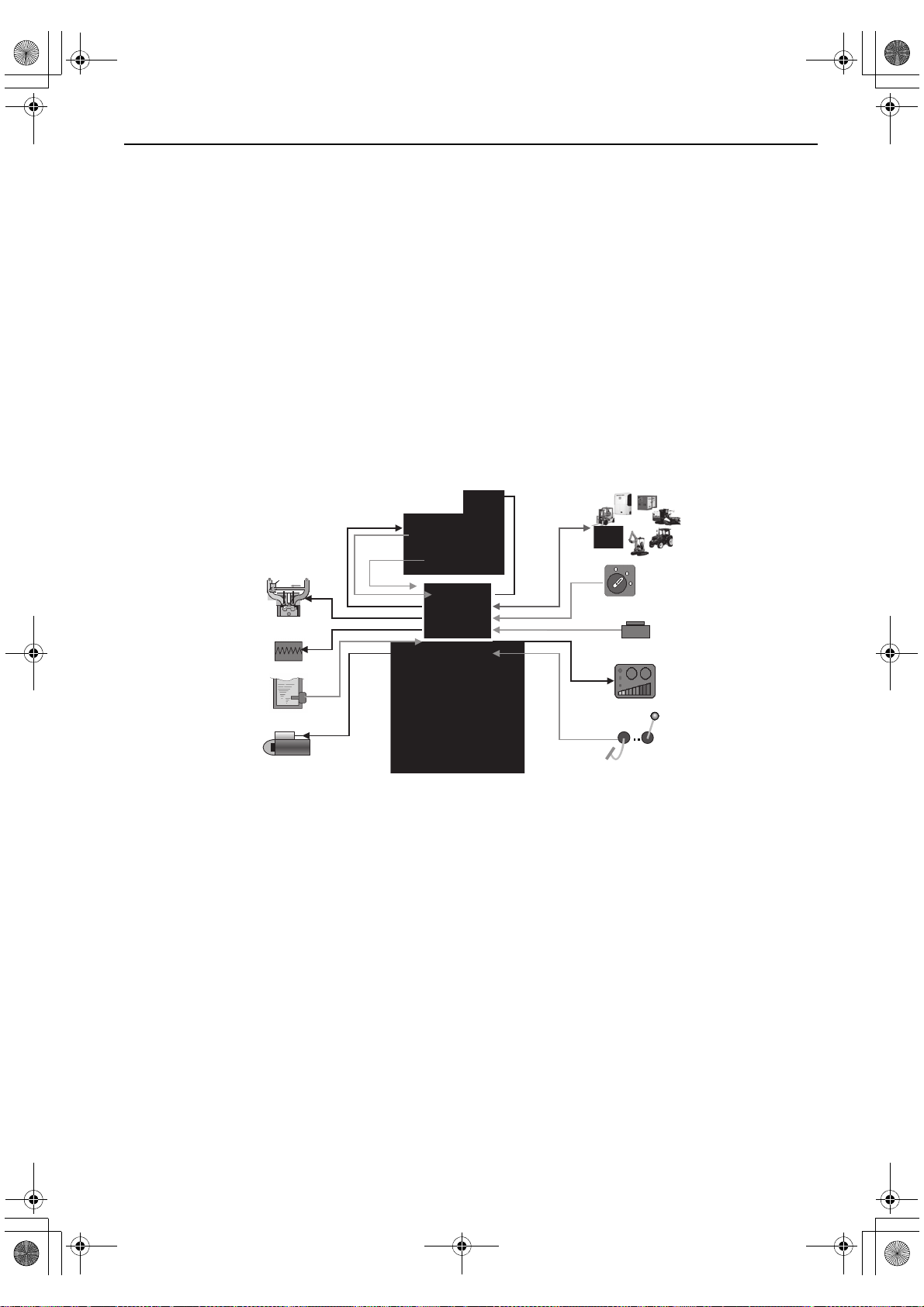
E-ECU
CSD
Engine speed
sensor
Rack position
sensor
Eco-governor
Fuel injection pump
Actuator
Intake Exhaust
EGR-Valve
Piston
Liner
Inj.Nozzle
Re-circulation
EGR
Starting aid
Coolant temperature
sensor
Starter
Operator's console
Stop switch
Key switch
OFF
Accelerator sensor
CAN
Engine
ON
START
TNV_OperationManual_T4(under 19kW).book Page 23 Wednesda y, June 17, 2015 11:23 AM
PRODUCT OVERVIEW
Model 3CE1 engine come with the Exhaust Gas
Recirculation (EGR) system to conform to the
engine emission regulations (EPA 2013 rules).
The EGR system and an electronic governor
(Eco-governor) constitute an electronic engine
control system.
The electronic engine control system regulates the
exhaust gas recirculation flow rate and the fuel
injection volume depending on the engine load and
speed signals from the engine controller (E-ECU),
so that the exhaust gas is kept clean according to
the emission control regulations. Figure 6
illustrates the electronic engine control system.
Features of the electronic engine control system
include:
• Engine speed control schemes
Droop control/Low-idling speed up/Auto
deceleration/High-idling speed down/Black smok e
suppression
• Starting aid
Auto preheating/After heating
• Engine failure detection
• CAN communication with the control system of
the driven machine
Consult the operation manual for the driven
machine for applicability of the features that
depends on the machine.
Figure 6
23
Page 30

TNV_OperationManual_T4(under 19kW).book Page 24 Wednesda y, June 17, 2015 11:23 AM
PRODUCT OVERVIEW
MAIN ELECTRONIC CONTROL COMPONENTS AND FEATURES
3CE1
Component/feature Description
Engine controller (E-E CU ) Adjusts the rack position of the fuel injec tion pump depending
on the speed command signal from the accelerator sensor, thus
regulating the engine speed and power. The engine controller
also regulates the opening of the EGR valve depending on the
engine speed and power. It serves as the master station for the
following component s/ control features.
Electronic governor (Eco-governor) Consists of the engine speed sensor, rack actuator, etc., and is
directly connected to the fuel injection pump in order to regulate
the rack position of the fue l injection pump depending on the
signals communicat ed wit h the E-ECU.
Fuel injection pump (fo r Ec o- gov ernor) Is of single plunger type and equipped with a CSD solenoid
valve that allows the fue l injection timing to advance and the
injection quantity to incr ease, thereby improving the cold start
performance of the engine.
EGR valve Controls the exhaust gas r eci r culation flow rate depending on
the engine speed/load signals from the E-ECU. It is installed on
the top of the exhaust man ifold.
Accelerator sensor Unlike mechanical governors, the Eco-governor has no
governor lever. The accelerator sensor serves as the governor
lever to provide the speed command signal (voltage signal) to
the E-ECU for engine speed control. It is installed in the
operator cabin of the driven machine. Constant speed engines
for e.g. generator use do not require accelerator sensors
because the engine speed can be shifted via a switch on the
operator's console.
Optional CAN communication capa bil ity is available as an option.
Fault indicator Is installed on the operat or ’s console. If a fault occurs in the
E-ECU or Eco-governor, the fault indicator flashes alerting the
operator to a fault. The number of flashes and/or the flashing
pattern vary depending on the type or source of the fault,
Optional
Engine diagnosis tool Allows the operator to troubleshoo t the cause of a problem
Option for service
Engine coolant temper at ure sensor Allows the C SD and ERG to be controlled in engine cold-start
enabling quick-fix.
based on detailed information regarding the problem occurring
in the E-ECU or Eco-governor. This tool can also be used for
data maintenance tasks including programming and mapping.
See Troubleshooting Char t on page 90.
conditions.
24
Page 31

TNV_OperationManual_T4(under 19kW).book Page 25 Wednesda y, June 17, 2015 11:23 AM
PRODUCT OVERVIEW
Component/feature Description
ON-glow at start Optional When the key switch is turned to the ON position, the glow plugs
are energized for up to 15 sec onds. The duration of
energization depends on t he engine coolant temperature. The
HEAT indicator is on during ener gization. When the i ndicator
goes out, turn the key switch to the START position to start the
engine.
Droop control Reduces the engine spee d by a certain percentage from no
load to full (rated) load in steady state operation. The same
percentage droop i s maintained even when the load increases
at any no-load speed.
Isochronous control Optional Offers a constant engine speed from no load to full load. The
engine speed does not decrease even when the load i ncreases
at any no-load speed.
Low-idling speed up
Increases the low-idling speed to up to 1000 min
depending on the engine coolant temperature. When the
coolant temperature reaches a predetermined value, this
feature returns the engine speed to the normal low idl e setting,
thus reducing the warm-up time.
High-idling speed down Optional Decreases the high-idling spe ed depending on the engine
coolant temperature. When the coolant temperature falls to a
predetermined value, this fe at ur e re tu rn s t he engine speed to
the normal high idle settin g, th us m i ni m i zi ng t he e m issi on of
white smoke at low temper at ures.
Auto deceleration Optional Brings the running engine in low idle mode automatically when
the accelerator pedal is not operated for a predetermined period
of time. When the pedal is operated, i.e., the accelerator sensor
is activated, the low idle mode is cancelled.
-1
(rpm)
25
Page 32

NOTICE
K0000023A
4
12
3
10
20
20
40
100
180
220
250
60
80
0
30
40
0
x100
RPM
VDO
VDO
PSI
F
C
0
1
2
3
4
5
bar
80
100
120
0
AUX
MC-704HP-G4
K0000024A
1
2
4
3
TNV_OperationManual_T4(under 19kW).book Page 26 Wednesda y, June 17, 2015 11:23 AM
PRODUCT OVERVIEW
GAUGES AND INDICATORS
The operator’s console provides you with the
means to start and stop the unit and a series of
gauges and indicators that inform you about the
current status of the engine. This is a required
engine component. Since the operator’s console is
application specific, it must be carefully sel ected by
an application engineer. It is not part of the basic
engine package as shipped from the Isuzu factory.
The illustrations and descriptions of optional
equipment in this manual, such as the operator’s
console, are for a typical engine installation. Refer
to the documentation supplied by the optional
equipment manufacturer for specific operation and
maintenance instructions.
Gauges
The following gauges are located on a typical
operator’s console. Some operator’s consoles may
not have the gauges described here or may have
different gauges.
Figure 7
Figure 8
Tachometer - The tachometer display
(Figure 7, (1)) or (Figure 8, (1)) shows the engine
speed in revolutions per minute (RPM).
Engine coolant temperature - The engine coolant
temperature display (Figure 7, (2)) or
(Figure 8, (2)) shows the temperature of the engine
coolant.
Engine oil pressure - The engine oil pressure
display (Figure 7, (3)) or (Figure 8, (3)) shows the
pressure of the engine oil.
Hour meter - The hour meter display
(Figure 7, (4)) or (Figure 8, (4)) shows the total
number of hours the engine has run. This is useful
for planning the Periodic Maintenance Procedures
on page 66.
26
Page 33

10
20
20
40
100
180
220
250
60
80
0
30
40
0
x100
RPM
VDO
VDO
PSI
F
C
0
1
2
3
4
5
bar
80
100
120
0
AUX
MC-704HP-G4
K0000024B
1
2
3
4
5
2
3
4
5
K0000025B
TNV_OperationManual_T4(under 19kW).book Page 27 Wednesda y, June 17, 2015 11:23 AM
PRODUCT OVERVIEW
Indicators
The following indicators are located on a typical
operator’s console.
Figure 9
1
HEAT indicator (Figure 9, (1)) - For the “ON-glow”
type of the starter switch that does not have the
HEAT position in the counterclockwise direction of
the ON position, by turning the key to the ON
position, the preheating function automatically
activates, and the HEAT indicator (Figure 9, (1))
lights up. 4 seconds after the indicator turns off is
when to start the operation. In the case of 3CE1
(DI), the indicator goes off after 15 seconds. Please
refer to HEAT on page 28 about the HEAT indicator
of the electronic controlled engine.
HEAT indicator (Figure 10, (1)) - When cold
starting the engine, in order to activate the glow
plug, the starter key needs to be turned to the
HEAT position (left side of OFF) (Figure 10, (5)).
By turning the key to the HEAT position and
keeping it at that position, the HEAT indicator
(Figure 10, (1)) lights up, and after 4 seconds, it
turns off. The time the indicator turns off is when to
start the operation. In the case of 3CE1 (DI), the
indicator goes off after 15 seconds.
Battery charge (Figure 9, (2)) or (Figure 10, (2)) When the key is turned to the ON position, the
charge indicator lights up. When the engine is
started, the alternator (or dynamo) generates
power, and the battery starts charging. Then the
indicator goes off. This indicator will also come on
when there is a problem in the charging system.
This indicator does not tell you the charging timing
(when the battery is low). See Troubleshooting
Chart on page 90.
Engine oil pressure (Figure 9, (3)) or
(Figure 10, (3)) - This indicator will come on if the
engine oil pressure is below or exceeds normal
limits. See Troubleshooting Chart on page 90.
Engine coolant temperature (Figure 9, (4)) or
(Figure 10, (4)) - This indicator will come on if the
engine coolant temperature exceeds normal limits.
See Troubleshooting Chart on page 90.
Figure 10
Auxiliary (Figure 9, (5)) - Used for special
applications.
27
Page 34

NOTICE
1
2
3
4
5
6
7
8
Optional key switch: Turning it
to ON energizes the glow plugs
automatically.
TNV_OperationManual_T4(under 19kW).book Page 28 Wednesda y, June 17, 2015 11:23 AM
PRODUCT OVERVIEW
GAUGES AND INDICATORS OF ELECTRONIC CONTROL SYSTEM
3CE1
Gauges
The following gauges are located on a typical
operator’s console of the electronically controlled
engines. Some operator’s consoles may not have
the gauges described here or may have different
gauges.
The illustrations and descriptions of optional
equipment in this manual, such as the operator’s
console, are for a typical engine installation. Refer
to the documentation supplied by the optional
equipment manufacturer for specific operation and
maintenance instructions.
Indicators
The following indicators are located on a typical
operator’s console.
See the Gauges and Indicators section for
description of indicators that are not described
below.
Fault (F igur e 11, (1)) (optio nal) - T his indica tor will
flash if a fault occurs in the E -ECU or Eco-governor .
The number of flashes and/or the flashing pattern
vary depending on the type or source of the fault.
See Troubleshooting Chart on page 90.
Auxiliary (Figure 11, (2)) - Rese rved as an
optional fault indicator.
HEAT (Figure 11, (3)) - This indicator will come on
when the glow plugs are energized when cold
starting the engine. For the electronic controlled
engine, by turning the key switch to the ON position
(Figure 11, (7)), the ECU detects the temperature
of the engine coolant, and the HEAT indicator turns
on for a preset period of time (Maximum 15
seconds), then the glow plug will be preheated. The
time the lamp came off is when to start the
operation.
When an optional after heater is installed, it is
energized for up to 80 sec. after the engine has
started, during which, however, the indicator is not
on.
Others (optional) - Other optional indicators
including those for indicating the air cleaner is
clogged or the water separator is filled with water
can also be installed on the console. See the
operation manual f or the driv en machine f or detai ls .
Machine events including alarms and faults are all
stored in memory of the E-ECU and can be loaded
into the service tool.
Figure 11
Figure 11 Typical Operator’s Console
28
Page 35

NOTICE
10
20
20
40
100
180
220
250
60
80
0
30
40
0
x100
RPM
VDO
VDO
PSI
F
C
0
1
2
3
4
5
bar
80
100
120
0
AUX
1
2
3
K0000011A
TNV_OperationManual_T4(under 19kW).book Page 29 Wednesda y, June 17, 2015 11:23 AM
PRODUCT OVERVIEW
CONTROLS
Key Switch
The key s witch for the operator’s console illustrated
in Figure 12 has three positio ns - OFF, ON, START
and HEAT.
MC-704HP-G4
Figure 12
NOTICE
For maximum engine life, Isuzu recommends that
when shutting the engine down, you allow the
engine to idle, without load, for five minutes. This
will allow the engine components that operate at
high temperatures, such as the turbocharger (if
equipped) and exhaust system, to cool slightly
before the engine itself is shut down.
OFF (key straight up and down) (Figure 12, (1))
and (Figure 13, (1)) - When y ou turn the key to this
position the engine shuts down. Electric current to
the gauges and indicators is shut off. You can insert
and remove the key in this position.
ON (Figure 12, (2)) and (Figure 13, (2)) - This is
the position the key will be in when the engine is
running. When the engine is not running, use this
position to energize the gauges, indicators, electric
fuel pump and auxiliary devices.
Never hold the key in the START position for longer
than 15 seconds or the starter motor will overheat.
START (Figure 12, (3)) and (Figure 13, (3)) - Turn
the key to this position to start the engine. As soon
as the engine starts, release the key and it will
automatically return to the ON position. Some key
switches may be equipped with a feature that
prevents you from turning the key to the START
position while the engine is running. When
operating a key switch with this feature, you cannot
turn the key to the START position without first
returning the key to the OFF position.
The key swi tch for the operator’s console illustrated
in Figure 13 has four positions - OFF, ON, START,
and HEAT.
29
Page 36

NOTICE
NOTICE
1
2
3
4
K0000021A
K0000648A
3
1
2
TNV_OperationManual_T4(under 19kW).book Page 30 Wednesda y, June 17, 2015 11:23 AM
PRODUCT OVERVIEW
Glow Plugs
Glow plugs help make the engine easy to start at
cold temperatures. During the engine starting
sequence, the glow plugs are activated for
approximately 4 seconds (15 seconds in case of
3CE1). After the pre-heat indicator goes out, the
engine can be started.
These plugs are installed in the cylinder head swirl
chambers for IDI engines or in the combustion
chambers for DI engines.
Governor Lever
Figure 13
For maximum engine life, Isuzu recommends that
when shutting the engine down, you allow the
engine to idle, without load, for five minutes. This
will allow the engine components that operate at
high temperatures, such as the turbocharger (if
equipped) and exhaust system, to cool slightly
before the engine itself is shut down.
Never hold the k e y in the START position for longer
than 15 seconds or the starter motor will overheat.
HEAT (Figure 13, (4)) - You must turn the key to
the HEAT position to activate the glow plug. The
indicator will flash for several seconds when you
turn the key to HEAT. You can turn the key to
START when the indicator goes out.
Figure 14
NOTICE
Never attempt to adjust the low or high idle speed
limit screw. This may impair the safety and
performance of the machine and shorten its life. If
adjustment is ever required, contact your Isuzu
Distributor.
The governor lever (Figure 14, (1)) controls the
engine speed. The lever is linked to the engine
speed control device in the driven machine.
The high idle speed limit screw (Figure 14, (2))
restricts the maximum engine speed when the
engine is operated without a load.
The low idle speed limit screw (Figure 14, (3)) sets
engine speed while it is idling.
30
Page 37

045045-00X00
1
Rack actuator
TNV_OperationManual_T4(under 19kW).book Page 31 Wednesda y, June 17, 2015 11:23 AM
Engine Stop Solenoid (IDI Engines)
PRODUCT OVERVIEW
Figure 16
Figure 15
When the key is turned to the ON position, the
engine stop solenoid (Figure 15, (1)) is energized
and allows the fuel injection pump to deliver fuel to
the engine, allowing the engine to be started. When
the key is turned to the OFF position, the engine
stop solenoid is de-energized and shuts off the fuel
supply from the fuel injection pump to the engine,
causing the engine to stop.
Speed Control of Electronically Controlled Engines
3CE1
The electronically controlled engines have no
governor lever. For these engines, the position
signal of the throttle lever or accelerator pedal of
the driven machine is converted into an electric
signal by the accelerator sensor Figure 16, which is
then delivered to the rack actuator of the
Eco-governor Figure 18 through the E-ECU
Figure 17, allowing the engine speed to be
controlled.
Figure 17
Figure 18
31
Page 38

Engine speed
Torque
30 %
100 %
110 %
120 %
2
100 %60 %
800 min
-1
1
1
2
3
4
TNV_OperationManual_T4(under 19kW).book Page 32 Wednesda y, June 17, 2015 11:23 AM
PRODUCT OVERVIEW
Electronic Engine Speed Control
3CE1
■ Start and stop of electronic controlled engines
The electronic controlled engines have no engine
stop solenoid. The ECU controls the engine
start/stop sequence.
■ Engine performance curves
Figure 20 shows typical engine speed curves that
outline the relationship between engine speed and
load.
Droop control
The VM series engines for general use are
designed so that the engine speed is reduced by a
certain percentage from 30 % load to full rated load.
See curves (1) in Figure 19 below. The same
percentage droop is maintained at any no-load
speed.
Isochronous control
The CL series consists of isochronous design
engines, the speed of which is kept constant from
no load to full rated load. See curves (2) in
Figure 19 below.
Some VM series engines for general use may be
custom-engineered and have the isochronous
capability. Consult the operation manual for the
driven machine for application details of such
engines.
Figure 19
Figure 20
Figure 20 Typical operator’s console and switch
arrangement
Low-idling speed up
This feature increases the low-idling speed to some
extent depending on the engine coolant
temperature. When the coolant temperature
reaches a predetermined value, this f eature returns
the engine speed to the normal low idle setting,
thus reducing the warm-up time.
32
Page 39

TNV_OperationManual_T4(under 19kW).book Page 33 Wednesda y, June 17, 2015 11:23 AM
Auto deceleration (optional)
This feature brings the running engine in low idle
mode automatically when the accelerator pedal is
not operated for a predetermined period of time.
When the pedal is operated, i.e., the accelerator
sensor is activated, the low idle mode is cancelled.
A certain ON/OFF combination of switches (1) - (4)
on the operator’s console Figure 20 will implement
this optional feature. For details, see the operation
manual for the driven machine.
High-idling speed down (optional)
This feature decreases the high-idling speed
depending on the engine coolant temperature.
When the coolant temperature falls to a
predetermined value, this feature returns the
engine speed to the normal high idle setting, thus
minimizing the emission of white smoke at low
temperatures.
PRODUCT OVERVIEW
A certain ON/OFF combination of switches (1) - (4)
on the operator’s console Figure 20 will implement
this optional feature. For details, see the operation
manual for the driven machine.
Others
Other optional features can be provided by
selecting certain ON/OFF combinations of switches
(1) - (4) on the operator’s console Figure 20 will
implement this optional f eature. For details, see the
operation manual for the driven machine.
33
Page 40

TNV_OperationManual_T4(under 19kW).book Page 34 Wednesda y, June 17, 2015 11:23 AM
PRODUCT OVERVIEW
This Page Intentionally Left Blank
34
Page 41

TNV_OperationManual_T4(under 19kW).book Page 35 Wednesda y, June 17, 2015 11:23 AM
TNV Operation Manual
BEFORE YOU
OPERATE
This section of the Operation Manual describes the
diesel fuel, engine oil, and engine coolant
specifications and how to replenish them. It also
describes the daily engine checkout.
35
Page 42

TNV_OperationManual_T4(under 19kW).book Page 36 Wednesda y, June 17, 2015 11:23 AM
BEFORE YOU OPERATE
DIESEL FUEL
Diesel Fuel Specifications
Diesel fuel should comply with the following
specifications. The table lists several worldwide
specifications for diesel fuels.
Diesel fuel specifica tion Location
ASTM D975
No. 1D S 1 5
No. 2D S 1 5
EN590:96 European Union
ISO 8217 DMX International
BS 2869-A1 or A2 United Kingdom
JIS K2204 Grade No. 2 Japan
KSM-2610 Korea
GB252 China
■ Additional technical fuel requirements
• When operating the engine in cold districts or
high altitudes, the fuel cetane number should be
equal to 45 or higher.
• The sulfur content must not exceed 15 ppm by
volume. A higher sulfur content fuel may
cause sulfuric acid corrosion in the cylinders
of the engines. Especially in U.S.A. and
Canada, Ultra Low Sulfur fuel must be used.
• Use the fuel that can be used where the
temperature is 12 °C (53.6 °F) lower than the
expected lowest temperature to prevent the fuel
from freezing.
USA
• PAH (Polycyclic Aromatic Hydrocarbons) content
should be below 10 % by volume.
• Metal content of Mg, Si, and Al should be equal to
or lower than 1 mass ppm. (Test analysis method
JPI-5S-44-95)
• The diesel fuel should be free from Zn and Na.
• Lubricity: Wear mark of WS1.4 should be Max.
0.018 in. (460 µm) at HFRR test.
■ Precautions and concerns regarding the
use of diesel fuel
• Never use kerosene.
• Never mix kerosene or used engine oil with the
diesel fuel.
• Never use residual fuels that cause diesel fuel
filter clogging and carbon deposits on the
nozzles.
• Never use fuels stored f or long time in a drum can
or the like.
• Never keep fuel in containers with zinc plating on
the inside.
• Never use fuels purchased from unauthorized
dealer.
• Fuel additives are not recommended. Some fuel
additives may cause poor engine performance.
Consult your Isuzu representative for more
information.
• Bio-diesel fuels. See Bio-diesel fuels on page 37.
• Water and sediment in the fuel s hould not e x ceed
0.05 % by volume.
• Ash content not to exceed 0.01 % by volume.
• Carbon residue content not to exceed 0.35 % by
volume. Less than 0.1 % is preferred.
• Total aromatics content should not exceed 35 %
by volume. Less than 30 % is preferred.
36
Page 43

TNV_OperationManual_T4(under 19kW).book Page 37 Wednesda y, June 17, 2015 11:23 AM
BEFORE YOU OPERATE
■ Bio-diesel fuels
General description of biodiesel
1. Biodiesel is a renewable , o xygenated fuel made
from agricultural and renewable resources
such as soybeans or rapeseeds. Biodiesel is a
fuel comprised of methyl or ethyl ester
oxygenates of long chain fatty acids derived
from the transesterification of vegetable oils,
animal fats, and cooking oils. It contains no
petroleum-based diesel fuel but can be
blended at any level with petroleum-based
diesel fuel. In case it is not blended with
petroleum-based diesel fuel such biodiesel is
referred to as “B100”, which means that it
consists of 100 % (pure) biodiesel. However,
most common biodiesel is blended with
conventional (petroleum-based) diesel fuel.
The percentage of the blend can be identified
by its name. For example, “B7” consists of 7 %
biodiesel and 93 % conventional diesel fuel.
The unprocessed vegetable oil is not
considered as diesel fuel.
2. Advantages of biodiesel:
• Biodiesel produces less visible smok e and a
lower amount of particulate matter.
• Biodiesel is biodegradable and nontoxic.
• Biodiesel is safer than con ventional diesel fuel
because of its higher flash point.
Following the increased interest in the reduction
of emissions and the reduction of the use of
petroleum distillate based fuels; many
governments and regulating bodies encourage
the use of biodiesel.
3. Disadvantages of biodiesel:
Concentrations that are higher than 7 % of
biodiesel (higher than B7) can hav e an adverse
affect on the engine’s perf ormance, its integrity
and/or durability . The risk of problems occurring
in the engine increases as the le v el of biodiesel
blend increases. The f ollowing negative aff ects
are exempl ary and typical for the usage of high
concentrated biodiesel blends:
• Biodiesel can accelerate the oxidation of
Aluminum, Brass, Bronz e, Copper and Zinc.
• Biodiesel damages, and finall y seeps through
certain seals, gaskets, hoses, glues and
plastics.
• Certain natural rubbers, nitride and butyl
rubbers will become harder and more brittle as
degradation proceeds when used with
biodiesel.
• The deteriorated biodiesel creates deposits i n
the engines.
• Due to its natural char acteristic, biodiesel will
decrease the engine output by appro ximately 2
percent (in case of B20) comparing to
conventional (petroleum-based) diesel fuel .
• The fuel consumption ratio will increase by
approximately 3 percent (in case of B20)
comparing to conventional d iesel fuel.
Approved engines
Isuzu C series engine can be operated with
biodiesel with concentrations up to B20. In case of
using biodiesel fuel up to B7 concentrations, no
special preparations etc. have to be made and the
original operating conditions and service intervals
as stated in the operating manuals apply. In case of
running below indicated engines with biodiesel
concentrations from B8 to B20, the required
operating conditions (see below Conditions for the
operation with biodiesel (from B8 to B20) ) have
to be observed.
Other than the following listed engines cannot be
run with biodiesel:
• 3CE1, 3CH1 and 3CJ1 Tier 4
37
Page 44

TNV_OperationManual_T4(under 19kW).book Page 38 Wednesda y, June 17, 2015 11:23 AM
BEFORE YOU OPERATE
Approved fuel
In case of using biodiesel (only concentrations up to
B20) such fuel should comply with the below
recommended standards. However, raw pressed
vegetable oils are not considered to be biodiesel
and are not acceptable for use as fuel in any
concentration in Isuzu engines.
1. EN14214 (European standard) and/or ASTM
D-6751 (American standard).
In North America, biodiesel and biodiesel
blends must be purchased from the BQ-9000
accredited producers and BQ-9000 certified
distributors.
2. All applicable engines can be operated with
biodiesel fuel up to B20 (20 % bio-fuel blend)
as a maximum concentration.
(For your information: In Japan, the legally
allowed maximum concentration for on-road
applications is B5.)
Conditions for the operation with biodiesel
(from B8 to B20)
When operating your applicable Isuzu C series
engine with biodiesel blends concentrated above
B8, we seriously recommend observing the
following operation, service and maintenance
conditions:
1. The original service interval of the below stated
services as indicated in the respective Isuzu
engine standard operation manual, the
application manual and the service manual
should be halved (please refer to your own
manuals for the each service interval):
• Replacement interval of engine oil filter , engine
oil and the fuel filter.
• Cleaning interval of the water separator
• Drain interval of the fuel tank.
2. It is required to inspect, clean and adjust the
fuel injector every 1000 operating hours.
3. Before using the bio-die sel fuel of B10 or higher,
replace the following parts.
• Fuel hose (The hose must be replaced every 2
years or 2000 hours regardless of the bio fuel
type.)
• O-ring of fuel filter
• O-ring of water separator
• When replacing a diaphragm type fuel f eed
pump to an electronic type, replace to the feed
pump and the pump cover i nstructed to the
attached list.
• If the water separator is not attached, it needs
to be attached.
Please refer to the attached list of exchange
parts for details.
4. Please use only biodiesel fuel that is
appropriate to the intended operation
environment of the engines. This especially
applies if the operating ambient temperature
falls below 0 degree centigrade.
5. In particular, operation with biodiesel requires
daily maintenance as follows:
• Please daily check the engine oil le vel. If the oil
level rises abo ve the oil lev el of the pre vious
day, the engine oil needs to be immediately
replaced.
• Please daily check the water l ev el of the water
separator. If the water le vel rises abo ve the
“max” indicator, an immediate drain of the
water separator is required.
6. Biodiesel blends up to B20 can only be used for
a limited time of up to 3 months of the date of
biodiesel manufacture. Therefore biodiesel
needs to be used at latest within 2 months from
the time of filling the tank or within 3 months
from the time of production by the fuel supplier ,
whichever comes first.
7. Before a long-term storage without operating
the engine, the biodiesel needs to be drained
out completely and the engine has to be run for
30 minutes with conventional diesel fuel as
indicated in your operation manual.
38
Page 45

TNV_OperationManual_T4(under 19kW).book Page 39 Wednesda y, June 17, 2015 11:23 AM
■ KIT parts list for B10 through B 20
3CH1, 3CJ1 3CE1
5-8640-2407-0 5-8640-2408-0
No need
No need
Need to change only O-ring.
P44: 5-8640-2246-0 --> A
Need to change only O-ring.
P44: 5-8640-2246-0 --> B
Fuel oil tank / - Fuel oil tank
Fuel feed pump
- Fuel oil filter
Fuel oil filter
- Fuel injection pump
Fuel injection pump
- Fuel oil filter
Cap, fuel injection no zzle
Fuel injection nozzle
-Fuel injection nozzle
Fuel injection nozzle
- Fuel injection pump
Fuel oil filter
Water separator
No. (1) (1)
Length 2000 2000
Part No. 5-8640-2241-0 5-8640-2241-0
Part name FO-T CMP FO-T CMP
Number 2 2
No. (3) (4)
Length 450 1000
Part No. 5-8640-2242-0 5-8640-2247-0
Part name FO-T CMP FO-T CMP
Number 1 1
No. (6) (5)
Length 270 220
Part No. 5-8640-2243-0 5-8640-2248-0
Part name FO-T CMP FO-T CMP
Number 1 1
No. (11) (7)
Length 450 300
Part No. 5-8640-2244-0 5-8640-2249-0
Part name FO-T CMP FO-T CMP
Number 1 1
Part No.
Part name
Number
No.
Length 115
Part No. 5-8640-1791-0
Part name FO-T CMP
Number 2
No. (16) (17)
Length 150 Formed pipe
Part No. 5-8640-2245-0 5-8640-2250-0
Part name FO-T CMP FO-T CMP
Number 1 1
BEFORE YOU OPERATE
5-8640-1423-0
5-8640-0112-0
CAP
CLIP
1
1
(13)
No need
(Because of cartridge type)
Need to change only O-ring.
G75 : 5-8640-2251-0 --> C
P16 : 5-8640-1755-0 --> D
P7 : 5-8640-2252-0 --> E
G65 : 5-8640-2418-0 --> C
(Need only for TAIYO-GIKEN)
Fuel feed pump
5-8640-2409-0
Electric feed pump: 5-8640-0024-0
Cover assy, feed pump: 5-8640-1927-0
39
Page 46

A
033051-00X
033050-00X
033042-00X
Part number
A 5-8640-2246-0 (P44)
B 5-8640-2246-0 (P44)
C 5-8640-2251-0 (G75)
D 5-8640-1755-0 (P16)
E 5-8640-2252-0 (P7)
TNV_OperationManual_T4(under 19kW).book Page 40 Wednesda y, June 17, 2015 11:23 AM
BEFORE YOU OPERATE
D
C
B
E
40
Page 47

NOTICE
K0000002A
3
1
2
TNV_OperationManual_T4(under 19kW).book Page 41 Wednesda y, June 17, 2015 11:23 AM
Filling the Fuel Tank
BEFORE YOU OPERATE
DANGER
Fire and Explosion Hazard!
• Diesel fuel is flammable and
explosive under certain
conditions.
• Only fill the fuel tank with diesel fuel. Filling
the fuel tank with gasoline may result in a fire
and will damage the engine.
• Never refuel with the engine running.
• Wipe up all spills immediately.
• Keep sparks, open flames or any other form of
ignition (match, cigarette, static electric
source) well away when refueling.
• Never overfill the fuel tank.
• Fill the fuel tank. Store any containers
containing fuel in a well-ventilated area, away
from any combustibles or sources of ignition.
• Be sure to place the diesel fuel container on
the ground when transferring the diesel fuel
from the pump to the container. Hold the hose
nozzle firmly against the side of the container
while filling it. This prevents static electricity
buildup which could cause sparks and ignite
fuel vapors.
• Never place diesel fuel or other flammable
material such as oil, hay or dried grass close
to the engine during engine operation or
shortly after shutdown.
• Before you operate the engine, check for fuel
leaks. Replace rubberized fuel hoses every
two years or every 2000 hours of engine
operation, whichever comes first, even if the
engine has been out of service. Rubberized
fuel lines tend to dry out and become brittle
after two years or 2000 hours of engine
operation, whichever comes first.
• Failure to comply will result in death or
serious injury.
• Only use diesel fuels recommended by Isuzu for
the best engine performance, to prevent engine
damage and to comply with EPA/ARB warranty
requirements.
• Only use clean diesel fuel.
• Never remove the primary strainer (if equipped)
from the fuel tank filler port. If removed, dirt and
debris could get into the fuel system causing it to
clog.
Note that a typical fuel tank is shown. The fuel tank
on your equipment may be different.
1. Clean the area around the fuel cap
(Figure 1, (1)).
2. Remove the fuel cap from the fuel tank
(Figure 1, (2)).
3. Observe the fuel level sight gauge
(Figure 1, (3)) and stop filling when gauge
shows fuel tank is full. Never overfill the fuel
tank.
4. Replace the fuel cap (Figure 1, (1)), hand
tighten. Over tightening the fuel cap will
damage it.
Figure 1
41
Page 48

DANGER
1
K0000649A
2
TNV_OperationManual_T4(under 19kW).book Page 42 Wednesda y, June 17, 2015 11:23 AM
BEFORE YOU OPERATE
Priming the Fuel System
Fire and Explosion Hazard!
• Diesel fuel is flammable and
explosive under certain
conditions.
• If the unit has an electric fuel pump, when you
prime the fuel system, turn the key switch to
the ON position for 10 to 15 seconds to allow
the electric fuel pump to prime the system.
• If the unit has a mechanical fuel pump, when
you prime the fuel system, operate the fuel
priming lever of the mechanical fuel pump
several times until the fuel filter cup is filled
with fuel.
• Failure to comply will result in death or
serious injury.
The fuel system needs to be primed
under certain conditions:
T o prime the fuel system if an electric fuel pump
is installed:
1. Turn the key to the ON position for 10 to 15
seconds. This will allow the electric fuel pump to
prime the fuel system.
2. Never use the starter motor to crank the engine
in order to prime the fuel system. This may
cause the starter motor to overheat and
damage the coils, pinion and/or ring gear.
To prime the fuel system if a mechanical fuel
pump is installed:
1. Operate the fuel priming lever (Figure 2, (1))
several times until the fuel filter cup
(Figure 2, (2)) is filled with fuel.
2. Never use the starter motor to crank the engine
in order to prime the fuel system. This may
cause the starter motor to overheat and
damage the coils, pinion and/or ring gear.
• Before starting the engine for the first time
• After running out of fuel and fuel has been added
to the fuel tank
• After fuel system maintenance such as changing
the fuel filter and draining the water separator, or
replacing a fuel system component.
Figure 2
42
Page 49

NOTICE
TNV_OperationManual_T4(under 19kW).book Page 43 Wednesda y, June 17, 2015 11:23 AM
ENGINE OIL
The fuel system needs to be primed
under certain conditions:
• Before starting the engine for the first time
• After running out of fuel and fuel has been added
to the fuel tank
• After fuel system maintenance such as changing
the fuel filter and draining the water separator, or
replacing a fuel system component.
To prime the fuel system:
1. Turn the key to the ON position for 10 to 15
seconds. This will allow the electric fuel pump to
prime the fuel system.
2. Never use the starter motor to crank the engine
in order to prime the fuel system. This may
cause the starter motor to overheat and
damage the coils, pinion and/or ring gear.
• Only use the engine oil specified. Other engine
oils may affect warranty coverage, cause internal
engine components to seize and/or shorten
engine life.
• Prevent dirt and debris from contaminating the
engine oil. Carefully clean the oil cap/dipstick and
the surrounding area before you remove the cap.
• Never mix different types of engine oil. This may
adversely affect the lubricating properties of the
engine oil.
• Never overfill. Overfilling may result in white
exhaust smoke, engine overspeed or internal
damage.
BEFORE YOU OPERATE
Engine Oil Specifications
Use an engine oil that meets or exceeds the
following guidelines and classifications:
■ Service categories
• API service categories CD, CF, CF-4, CI-4
(Use an API CF or higher quality oil for
electronically controlled engines.)
• ACEA service categories E-3, E-4, and E-5
• JASO service category DH-1
■ Definitions
• API classification (American Petroleum Institute)
• ACEA classification (Association des
Constructeurs Européens d’Automobilies)
• JASO (Japanese Automobile Standards
Organization)
43
Page 50

-30°C -20°C -10°C 0 10°C 20°C 30°C
SAE 5W-30
SAE 15W-40
SAE 20
SAE 30
SAE 10W-30
K0000005A05
40°C
4
5
1
2
3
K0000587AX
4
TNV_OperationManual_T4(under 19kW).book Page 44 Wednesda y, June 17, 2015 11:23 AM
BEFORE YOU OPERATE
Note:
• Be sure the engine oil, engine oil storage
containers, and engine oil filling equipment are
free of sediments and water.
• Change the engine oil after the first 50 hours of
operation and then at every 250 hours thereafter.
• Select the oil viscosity based on the ambient
temperature where the engine is being operated.
See the SAE Service Grade Viscosity Chart
(Figure 3).
• Isuzu does not recommend the use of engine oil
“additives.”
■ Additional technical engine oil
requirements:
The engine oil must be changed when the Total
Base Number (TBN) has been reduced to 1.0
mgKOH/g. TBN (mgKOH/g) test method; JIS
K-201-5.2-2 (HCI), ASTM D4739 (HCI).
Engine Oil Viscosity
Select the appropriate engine oil viscosity based on
the ambient temperature and use the SAE service
grade viscosity chart in Figure 3.
Checking Engine Oil
1. Make sure engine is level.
2. Remove dipstick (Figure 4, (1)) and wipe with
clean cloth.
3. Fully reinsert dipstick.
4. Remove dipstick. The oil level should be
between upper (Figure 4, (2)) and lower
(Figure 4, (3)) lines on the dipstick.
5. Fully reinsert dipstick.
Adding Engine Oil
1. Make sure engine is level.
2. Remove oil cap (Figure 4, (4)).
3. Add indicated amount of engine oil at the top or
side engine oil filler port (Figure 4, (5)).
4. Wait three minutes and check oil level.
5. Add more oil if necessary.
6. Reinstall oil cap (Figure 4, (4)) and
hand-tighten. Over-tightening may damage the
cap.
44
Figure 3
Page 51

045046-00X01
2
4
1
4
3
TNV_OperationManual_T4(under 19kW).book Page 45 Wednesda y, June 17, 2015 11:23 AM
Engine Oil Capacity (Typical)
Note: These are the engine oil capacities
The following are the engine oil capacities for
various Isuzu C series engine.
BEFORE YOU OPERATE
associated with a “Deep Standard” oil pan.
Oil capacity will vary dependent upon which
optional oil pan is used. Refer to the
operation manual provided by the driven
machine manufacturer for the actual engine
oil capacity of your machine.
Engine oil capacity (typical)
Figure 4
CAUTION
To refuel the engine oil, refuel slowly after
removing the dipstick and both caps. If you
refuel rapidly, the oil intrusion to the intake
occurs through the PCV valve of the valve
cover. It will result in an oil hammer at engine
start, which may cause damage to the engine.
Engine model
3CH1-NGZG01
3CH1-SDZP01
3CJ1-NGZG01 3,0/1,6 qt (2,8/1,5 ℓ)
3CJ1-SDZP01 3.1/1.7 qt (2.9/1.6 ℓ)
Engine oil capacity (typical)
Engine model
3CE1 7.1/4.1 qt (6.7/3.9 ℓ)
Dipstick
upper limit/lower limit
3.6/1.9 qt (3.4/1.8 ℓ)
Dipstick
upper limit/lower limit
45
Page 52

DANGER
WARNING
TNV_OperationManual_T4(under 19kW).book Page 46 Wednesda y, June 17, 2015 11:23 AM
BEFORE YOU OPERATE
ENGINE COOLANT
Scald Hazard!
• Never remove the radiator cap if
the engine is hot. Steam and
hot engine coolant will spurt
out and seriously burn you.
Allow the engine to cool down
before you attempt to remove
the radiator cap.
• Tighten the radiator cap securely after you
check the radiator. Stea m can spurt out during
engine operation if the cap is loose.
• Always check the level of the engine coolant
by observing the reserve tank.
• Failure to comply will result in death or
serious injury.
Burn Hazard!
• Wait until the engine cools
before you drain the engine
coolant. Hot engine coolant
may splash and burn you.
• Failure to comply could result in death or
serious injury.
CAUTION
Coolant Hazard!
• Wear eye protection
and rubber gloves
when you handle
long life or extended
life engine coolant. If
contact with the eyes
or skin should occur,
flush eyes and wash
immediately with
clean water.
• Failure to comply may result in minor or
moderate injury.
NOTICE
• Only use the engine coolant specified. Other
engine coolants may affect warranty coverage,
cause an internal buildup of rust and scale and/or
shorten engine life.
• Prevent dirt and debris from contaminating the
engine coolant. Carefully clean the radiator cap
and the surrounding area before you remove the
cap.
• Never mix different types of engine coolants. This
may adversely affect the properties of the engine
coolant.
46
Page 53

FULL
LOW
K0000029A
5
3
6
4
2
1
045047-00X00
1
TNV_OperationManual_T4(under 19kW).book Page 47 Wednesda y, June 17, 2015 11:23 AM
BEFORE YOU OPERATE
Engine Coolant Specifications
Use a Long Life Coolant (LLC) or an Extended Life
Coolant (ELC) that meets or exceeds the following
guidelines and specifications.
• ASTM D6210, D4985 (US)
• JIS K-2234 (Japan)
• SAE J814C, J1941, J1034 or J2036
(International)
■ Alternative engine coolant
If an Extended or Long Life Coolant is not availab le,
alternatively, you may use an ethylene glycol or
propylene glycol based conventional coolant
(green).
NOTICE
• Always use a mix of coolant and water . Ne v er use
water only.
• Mix coolant and water per the mixing instructions
on the coolant container.
• Water quality is important to coolant performance.
Isuzu recommends that soft, distilled or
demineralized water be used to mix with c oolants.
• Never mix extended or long life coolants and
conventional (green) coolants.
Filling Radiator with Engine Coolant
Fill the radiator and reserve tank as follows. This
procedure is for filling the radiator for the first time
or refilling it after it is flushed. Note that a typical
radiator is illustrated.
1. Check to be sure the radiator drain plug is
installed and tightened or the drain valve
(Figure 5, (1)) is closed. Also make sure the
coolant drain plug (Figure 6, (1)) in the cylinder
block is closed.
Figure 5
• Never mix different types and/or colors of
extended life coolants.
• Replace the coolant every 1000 engine hours or
once a year.
Figure 6
47
Page 54

TNV_OperationManual_T4(under 19kW).book Page 48 Wednesda y, June 17, 2015 11:23 AM
BEFORE YOU OPERATE
2. Remove the radiator cap (Figure 5, (2)) by
turning it counterclockwise about 1/3 of a turn.
3. Pour the engine coolant slowly into the radiator
until it is even with the lip of the engine coolant
filler port. Make sure that air bubbles do not
develop as you fill the radiator.
4. Reinstall the radiator cap (Figure 5, (2)). Align
the tabs on the back side of the radiator cap
with the notches on the engine coolant filler
port. Press down and turn the cap clockwise
about 1/3 of a turn.
5. Remove the cap of the reserve tank
(Figure 5, (3)), and fill it to the LOW (COLD)
mark (Figure 5, (4)) with engine coolant.
Reinstall the cap.
6. Check the hose (Figure 5, (5)) that connects
the reserve tank (Figure 5, (3)) to the radiator.
Be sure it is securely connected and there are
no cracks or damage. If the hose is damaged,
engine coolant will leak out instead of going into
the reserve tank.
7. Run the engine until it reaches operating
temperature. Check the level of engine coolant
in the reserve tank When the engine is running
and the engine coolant is at normal
temperature, the coolant level in the reserve
tank should be at or neat the FULL (HOT) mark
(Figure 5, (6)). If the coolant is not at the FULL
(HOT) mark, add coolant to the reserve tank to
bring the coolant level to the FULL (HOT) mark.
Daily Check of the Cooling System
1. Check the level of engine coolant in the reserve
tank. When the engine is cold, the coolant level
in the tank should be at or slightly above the
LOW (COLD) mark (Figure 5, (4)) on the
coolant reserve tank.
If the coolant lev el is at the FULL (HO T) mark
(Figure 5, (6)) when the engine is c old, the
coolant will expand when it becomes hot and
possibly spray out of the overflo w hose.
2. Add additional engine coolant to the reserve
tank if necessary.
3. Check the radiator hoses for cracks, abrasions,
cuts or other damage. Replace as necessary.
Engine Coolant Capacity (Typical)
Note: Capacities listed are for the engine only
without a radiator. Refer to the operation
manual provided by the driven machine
manufacturer for actual engine coolant
capacity on your machine.
The following are the engine coolant capacities for
various Isuzu C series engine.
Engine coolant capacity (t ypical)
Engine model
3CH1-NGZG01
3CH1-SDZP01
3CJ1-NGZG01 1.0 qt (0.9 ℓ)
3CJ1-SDZP01 1.1 qt (1.0 ℓ)
Engine coolant capacity
1.0 qt (0.9 ℓ)
48
Engine coolant capacity (t ypical)
Engine model
3CE1 2.1 qt (2.0 ℓ)
Engine coolant capacity
Page 55

WARNING
NOTICE
TNV_OperationManual_T4(under 19kW).book Page 49 Wednesda y, June 17, 2015 11:23 AM
BEFORE YOU OPERATE
DAILY CHECKS
Before you begin any job, make sure the Isuzu C
series engine is in good operating condition. Make
sure you check the following items before you start
your shift and have any repairs completed before
you start work.
High-Pressure Hazard!
• Avoid skin contact with the
high-pressure diesel fuel spray
caused by a fuel system leak
such as a broken fuel injection
line. High-pressure fuel can
penetrate your skin and result
in serious injury. If you are
exposed to high-pressure fuel
spray, obtain prompt medical
treatment.
• Never check for a fuel leak with your hands.
Always use a piece of wood or cardboard.
Have your Isuzu Distributor repair the
damage.
• Failure to comply could result in death or
serious injury.
NOTICE
Make it a habit to perform daily checks. See Daily
Checks in the Before You Operate Section of this
manual.
Periodic maintenance prevents unexpected
downtime, reduces the number of accidents due to
poor machine performance and helps extend the
life of the engine.
Visual Checks
1. Check for engine oil leaks.
2. Check for fuel leaks.
3. Check for engine coolant leaks.
4. Check for damaged or missing parts.
5. Check for loose, missing or damaged fasteners.
6. Check the electrical harnesses for cracks,
abrasions, and damaged or corroded
connectors.
7. Check hoses for cracks, abrasions, and
damaged, loose or corroded clamps.
8. Check and clean radiator fins as necessary.
See Check and clean radiator fins on page 76.
9. Check the water separator for presence of
water and contaminants. If you find any water or
contaminants, drain the water separator. See
Drain water separator on page 71. If you have
to drain the water separator frequently , drain the
fuel tank and check for the presence of water in
your fuel supply. See Drain fuel tank on
page 75.
If any problem is noted during the visual check, the
necessary corrective action should be taken before
you operate the engine.
Check Diesel Fuel, Engine Oil and Engine Coolant Levels
Follow the procedures in Diesel Fuel on page 36,
Engine Oil on page 43 and Engine Coolant on page
46 to check these levels.
Check Engine Speed Control
Check the engine speed control for smooth
operation, adjust and lubricate or clean as
necessary. See Check and adjust the governor
lever and engine speed control (except
electronically controlled engines) on page 77.
49
Page 56

AUX
K0000009AX01
1
2
3
4
5
K0000025AX
1
2
3
4
3CE1
1
2
3
4
5
6
TNV_OperationManual_T4(under 19kW).book Page 50 Wednesda y, June 17, 2015 11:23 AM
BEFORE YOU OPERATE
Check Operator’s Console
Before you operate the engine you should make
sure that all of the indicators are functioning
properly.
Check Indicators
Isuzu C series engine are available with various
operator’s consoles. In the below Figures, three
types of typical operator’ s console including the one
for electronic controlled engines are shown as
examples.
HEAT
Figure 8 shows a typical indicator arrangement on
the operator’s console. With the specification of
standard glow (preheat), as you turn the key switch
to the HEAT position, the HEAT indicator is turned
on for 4 seconds, showing that the glow plugs are
energized. When the indicator goes off , turn the ke y
switch to START position and start the engine. In
the case of 3CE1 (DI), the indicator goes off after
15 seconds.
Figure 9
Figure 7
Figure 8
Figure 7 shows an indicator arrangement with the
specification for ON-glow. As you turn the key
switch to ON position, the HEAT indicator is turned
on for 4 seconds. When the indicator goes off, turn
the key switch to the START position and start the
engine. In the case of 3CE1 (DI), the indicator goes
off after 15 seconds.
Figure 9 shows an operator’s console of an
electronic controlled engine. The electronic
controlled engine has an ON-glow specification.
Depending on the water temperature, the heat
indicator will turn on for 15 seconds at the longest,
and preheats the glow plugs. When the indicator
goes off, turn the key switch to the START position
and start the engine.
50
Page 57

TNV_OperationManual_T4(under 19kW).book Page 51 Wednesda y, June 17, 2015 11:23 AM
Battery charge (Figure 7, (2)) or (Figure 8, (2)) or
(Figure 9, (4)) - Stays on until the engine is running
and the alternator is supplying charging current.
This indicator does not indicate whether the battery
is discharged.
Engine oil pressure (Figure 7, (3)) or
(Figure 8, (3)) or (Figure 9, (5)) - Stays on until the
engine is running and the oil pressure is within
normal limits.
Engine coolant temperature (Figure 7, (4)) or
(Figure 8, (4)) or (Figure 9, (6)) - Stays on
momentarily. Comes back on if engine overheats.
Auxiliary (Figure 7, (5)) or (Figure9, (2)) - Stays
on momentarily. Used for special applications.
Here is a summary of how these indicators
function. The table shows what happens when you
turn the key in a certain direction (e.g., OFF to ON).
BEFORE YOU OPERATE
Fault indicator (Figure 9, (1)) (optional) -
Illuminates for approx. 2 sec. when the key sw itch is
turned to ON, and stays off while the engine is
running. If a fault occurs in the Eco-governor
system or during energization of the E-ECU, this
indicator will flash in a certain pattern to indicate
what fault has occurred. See the troubleshooting
section for details.
51
Page 58

TNV_OperationManual_T4(under 19kW).book Page 52 Wednesda y, June 17, 2015 11:23 AM
BEFORE YOU OPERATE
Indicator OFF to HEAT OFF to ON ON to OFF
IDI (3CH1, 3CJ1) turns off
after indicating for 4 seconds.
DI (3CE1 ) turns off after
indicating for 15 seconds.
ON-glow
HEAT
type
Figure 7, (1)
Figure 8, (1)
Figure 9, (3)
HEAT
position
available
on key
switch
Battery ch arge
Figure 7, (2)
Figure 8, (2)
Figure 9, (4)
Engine oil pressure
Figure 7, (3)
Figure 8, (3)
Figure 9, (5)
Engine coolant temperature
Figure 7, (4)
Figure 8, (4)
Figure 9, (6)
Auxiliary
Figure 7, (5)
Figure 9, (2)
Fault (optional)
Figure 9, (1)
3CE1
Glow NA
IDI (3CH1, 3CJ1) turns off
Glow
after indicating for 4 seconds.
DI (3CE1) turns off after
indicating for 15 seconds.
NA ON
NA ON
NA ON
NA ON
NA Lights for 2 sec. only.
Note that, for electronic
control type engines (3CE1),
the indicators are controlled
from 1 to 15 seconds
depending on the
temperature of co oling water.
OFF
OFF OFF
OFF (Stays on until
alternator is supplying
charging current.
Remains on if there is a
problem in the charging
system. This indicator
does not indicate
whether the battery is
discharged.)
OFF (Stays on until oil
pressure reaches
normal operating
pressure. Remains on,
or comes back on, if
there is a pr obl e m in t he
lubrication system.)
OFF (Stays on
momentarily. Comes
back on if there is a
problem in the cooling
system.)
OFF
OFF (Flashes or
intermittently lights if a
fault occurs in the
E-ECU or
Eco-governor.)
52
Page 59

TNV_OperationManual_T4(under 19kW).book Page 53 Wednesda y, June 17, 2015 11:23 AM
TNV Operation Manual
ENGINE OPERATION
This section of the Operation Manual describes the
procedures for starting the engine, checking engine
performance during operation, and shutting the
engine down.
53
Page 60

NOTICE
c
o
1
2
K0000655A
K0000012B
1
2
AUX
K0000009BX
3
1
2
4
TNV_OperationManual_T4(under 19kW).book Page 54 Wednesda y, June 17, 2015 11:23 AM
ENGINE OPERATION
STARTING ENGINE
Use the following procedure to start the engine.
Note that two typical operator’ s consoles are shown
for illustrative purposes only.
1. Make sure you follow the procedures stated in
the Daily Checks on page 49.
2. Before first starting electronically controlled
engines 3CE1: The E-ECU of the electronically
controlled engines shown above needs to be
initialized at initial power up. When the fault
indicator comes on at initial power up, the
E-ECU has finished initialization. Then always
turn the key switch to the OFF position once
before starting the engine. (The E-ECU has
usually been initialized before the driven
machine is delivered).
From the second power up, make sure the fault
indicator is on for 2 sec. when turning the key
switch to the ON position.
3. Make sure the water separator fuel valve
(Figure 1, (1)) is in the ON position
(Figure 1, (2)).
4. Set the transmission (if equipped) in the
NEUTRAL position.
5. Disengage the PTO (if equipped).
6. Set the engine speed control to the
mid-position.
Figure 2
Never use an engine starting aid such as ether.
Engine damage will result.
7. Insert the key int o the key switch (Figure 2, (1))
or (Figure 3, (1)).
Figure 1
54
Page 61

NOTICE
K0000025C
3
5
4
1
2
TNV_OperationManual_T4(under 19kW).book Page 55 Wednesda y, June 17, 2015 11:23 AM
10. If the engine fails to start:
Figure 3
8. Turn the key to the ON position (Figure 2, (2))
or the HEAT position (Figure 3, (2)). The
pre-heat indicator (Figure 2, (3)) flashes for
several seconds and then goes out. After the
pre-heat indicator goes out you can start the
engine.
Note: The glow plugs are used to assist
starting in cold weather conditions. If you
are operating your engine in normal or
warm weather conditions, you may
bypass the Pre-Heat/Heat functions and
go directly to Start.
ENGINE OPERATION
1- Wait until the engine comes to a complete
stop before you attempt to start it again.
Engaging the starter while the engine is still
rotating will result in damage to the starter
and flywheel.
Note: Some key s witc hes are equipped with an
interlock that will not allow you to
re-engage the starter without first turning
the key to the OFF position.
2- Wait at least 30 seconds before you attempt
to start the engine again. This procedure will
allow the battery voltage to recover and
prevent damage to the starter motor due to
the low battery voltage.
Never hold the key in the ST AR T position for
longer than 15 seconds or the starter motor will
overheat.
9. Turn the key clockwise to the START position
(Figure 2, (4)) or (Figure 3, (4)). Release the
key as soon as the engine starts. It will return to
the ON position (Figure 2, (2)) or
(Figure 3, (5)).
Note: The starter of electronically controlled
engines 3CE1 will start with a delay of
approx. 0.5 sec. after the key switch has
been turned to the ON position. This is
because the E-ECU self-diagnostics has
run and is not a failure.
55
Page 62

WARNING
TNV_OperationManual_T4(under 19kW).book Page 56 Wednesda y, June 17, 2015 11:23 AM
ENGINE OPERATION
HIGH-ALTITUDE INJECTION CONTROL DEVICE
COLD START DEVICE
3CH1, 3CJ1
This series has a high-altitude injection control
Sudden Movement Hazard!
• Engaging the transmission or PTO at an
elevated engine speed could result in
unexpected movement of the equipment.
• Failure to comply could result in death or
serious injury.
The cold start device on direct injection models
improves engine starting at lower temperatures.
• If the engine cooling system temperature is below
5 °C (41 °F), the cold start device automatically
advances the fuel injection timing and slightly
increases the fuel injection volume.
• The engine idle speed will be slightly elevated for
approximately the first 5 minutes of operation.
• When the cold start device is activated, you may
notice a slight increase in the amount of exhaust
smoke. This is normal.
• Never engage the transmission or PTO while the
cold start device is activated or unexpected
movement of the machine may result.
device installed. It suppresses black smoke when
operating at high altitudes and at the same time
aims to control particulate matter.
The device consists of an output control solenoid
that is attached to the fuel injection pump and a
solenoid driver (with an atmospheric pressure
sensor) that is assembled on the implement side.
The output control solenoid actuates at engine
start. (It does not actuate during engine operation.)
At engine start, the starter operates and the engine
starts running. 4 seconds after the starter turns off,
the solenoid driver measures the atmospheric
pressure and determines whether to actuate the
solenoid. (The solenoid is energized during normal
operation, but it is turned off during the start of the
control device.) If at this time the atmospheric
pressure sensor determines that the altitude is
2624 ft (800 m) or more, the control device
operates. It reduces the fuel injection amount and
thus controls the occurrence of black smoke.
Because of this reduction in the injection amount,
the output decreases. At 5500 ft (1676 m), the
decrease in output (i.e. torque) is 20 % of the
maximum at low altitudes. Therefore, only apply
medium to low load when operating at high
altitudes.
56
NOTICE
The injection control device does not actuate during
engine operation. (Switch operation is not
performed.) Therefore, when the control device is
not yet operating and the machine is moved to a
high altitude during operation, or when the control
device is already operating and the machine is
moved to a low altitude, turn the key switch to OFF
(engine stop). This resets the control device. After
re-starting the engine, the necessity for injection
control is again determined.
Page 63

WARNING
NOTICE
Control solenoid
045348-00X00
TNV_OperationManual_T4(under 19kW).book Page 57 Wednesda y, June 17, 2015 11:23 AM
CHECKING THE ENGINE DURING OPERATION
Figure 4
• Never check for a fuel leak with your hands.
Always use a piece of wood or cardboard.
Have your Isuzu Distributor repair the
damage.
• Failure to comply could result in death or
serious injury.
ENGINE OPERATION
High-Pressure Hazard!
• Avoid skin contact with the
high-pressure diesel fuel spray
caused by a fuel system leak
such as a broken fuel injection
line. High-pressure fuel can
penetrate your skin and result
in serious injury. If you are
exposed to high-pressure fuel
spray, obtain prompt medical
treatment.
Make sure the engine is installed on a lev el surf ace.
If a continuously running engine is installed at an
angle greater than (IDI = 25°, DI = 30°) in any
direction or if an engine runs for short periods of
time (less than three minutes) at an angle greater
than (IDI = 30°, DI = 35°) in any direction, engine oil
may enter the combustion chamber causing
excessive engine speed and white exhaust smoke.
This may cause serious engine damage.
57
Page 64

NOTICE
NOTICE
4
1
2
3
K0000023B
5
10
20
20
40
100
180
220
250
60
80
0
30
40
0
x100
RPM
VDO
VDO
PSI
F
C
0
1
2
3
4
5
bar
80
100
120
0
AUX
MC-704HP-G4
1
3
4
2
5
K0000024C
TNV_OperationManual_T4(under 19kW).book Page 58 Wednesda y, June 17, 2015 11:23 AM
ENGINE OPERATION
New engine break-in:
• On the initial engine start-up, allow the engine to
idle for approximately 15 min utes while you check
for proper engine oil pressure, diesel fuel leaks,
engine oil leaks, coolant leaks, and for proper
operation of the indicators and/or gauges.
• During the first hour of operation, vary the engine
speed and the load on the engine. Short periods
of maximum engine speed and load are
desirable. Avoid prolonged operation at minimum
or maximum engine speeds and loads for the ne xt
four to five hours.
• During the break-in period, carefully observe the
engine oil pressure and engine temperature.
• During the break-in period, check the engine oil
and coolant levels frequently.
Never engage the starter motor while the engine is
running. This may damage the starter motor pinion
and/or ring gear.
1. While the engine is running, check the gauges
for normal indications. The gauges shown in
Figure 6 and Figure 5 are provided for
illustrative purposes only.
Figure 5
Figure 6
• Tachometer (Figure 6, (1)) or (Figure 5, (1))
-Make sure the engine speed is wi thin normal
limits.
• Engine oil pressure (Figure 6, (2)) or
(Figure 5, (3)) - Make sure the engine oil
pressure is within normal limits. See Principal
Engine Specifications on page 105.
• Engine coolant temperature (Figure 6, (3))
or (Figure 5, (2)) - Make sure the engine
coolant temperature is within normal limits.
• Hour meter - The hour meter display
(Figure 6, (4)) or (Figure 5, (4)) shows the
total number of hours the engine has run. This
is useful for planning periodic maintenance
operations. See Periodic Maintenance
Schedule on page 64.
• If any of the gauges shows an out of normal
limits condition, shut down the engine and have
the necessary repairs performed.
58
Page 65

NOTICE
TNV_OperationManual_T4(under 19kW).book Page 59 Wednesda y, June 17, 2015 11:23 AM
ENGINE OPERATION
2. After the engine has reached operating
temperature, all of the indicators (Figure 6, (5))
or (Figure 5, (5)) should be off. If any of the
indicators are on, shut down the engine and
have the necessary repairs performed.
3. Check for white or black smoke from the
exhaust system. A small amount of white
exhaust smoke is normal on start-up of a cold
engine. Black exhaust smoke could mean the
engine is overloaded or is being over-fueled. If
either of these conditions persists, contact your
Isuzu Distributor.
4. Check for abnormal sounds or vibration. In
some applications the engine and its mounting
may start to resonate and cause unusual
vibrations at certain engine speeds. Avoid
running the engine at these speeds. If the
abnormal sounds or vibration cannot be
resolved, shut down the engine and have the
necessary repairs performed. Contact your
Isuzu Distributor.
5. Check for any fuel, engine coolant or engine oil
leaks. If any leaks are found shut down the
engine and have the necessary repairs
performed.
6. Check the fuel level during operation. If the fuel
level runs low, stop the engine and refuel.
ADJUST ENGINE SPEED
New engine break-in:
• On the initial engine start-up, allow the engine to
idle for approximately 15 minutes while y ou check
for proper engine oil pressure, diesel fuel leaks,
engine oil leaks, coolant leaks, and for proper
operation of the indicators and/or gauges.
• During the first hour of operation, vary the engine
speed and the load on the engine. Short periods
of maximum engine speed and load are
desirable. Avoid prolonged operation at minimum
or maximum engine speeds and loads f or the next
four to five hours.
• During the break-in period, carefully observe the
engine oil pressure and engine temperature.
• During the break-in period, check the engine oil
and coolant levels frequently.
Use the engine speed control to adjust the engine
speed for the task that will be performed.
59
Page 66

NOTICE
AUX
K0000009C
1
K0000025D
1
TNV_OperationManual_T4(under 19kW).book Page 60 Wednesda y, June 17, 2015 11:23 AM
ENGINE OPERATION
SHUTTING DOWN THE ENGINE
For maximum engine life, Isuzu recommends that
when shutting the engine down, you allow the
engine to idle, without load, for five minutes. This
will allow the engine components that operate at
high temperatures, such as the turbocharger (if
equipped) and exhaust system, to cool slightly
before the engine itself is shut down.
Follow these steps to shut down the engine:
1. Disengage the PT O and/or set the tr ansmission
to NEUTRAL (if equipped).
2. Set the engine speed control to its lowest
setting.
3. Run the engine at low idle speed for at least fiv e
minutes before you shut it down.
4. Turn the key to the OFF position (Figure 7, (1))
or (Figure 8, (1)) and remove it from the key
switch.
Figure 8
5. If the engine will not be used for six months or
longer, follow the additional instructions in
Long-Term Storage on page 99.
Figure 7
60
Page 67

TNV_OperationManual_T4(under 19kW).book Page 61 Wednes day, June 17, 2015 11:23 AM
TNV Operation Manual
PERIODIC
MAINTENANCE
This section of the Operation Manual describes the
procedures for proper care and maintenance of the
engine.
61
Page 68

WARNING
TNV_OperationManual_T4(under 19kW).book Page 62 Wednesda y, June 17, 2015 11:23 AM
PERIODIC MAINTENANCE
PRECAUTIONS
The Importance of Periodic Maintenance
Engine deterioration and wear occurs in proportion
to length of time the engine has been in s ervice and
the conditions the engine is subject to during
operation. Periodic maintenance prevents
unexpected downtime, reduces the number of
accidents due to poor machine performance and
helps extend the life of the engine.
Performing Periodic Maintenance
Exhaust Hazard!
• Never operate the engine in an
enclosed area such as a garage,
tunnel, underground room,
manhole or ship’s hold without
proper ventilation.
• Never block windows, vents, or other means
of ventilation if the engine is operating in an
enclosed area. All internal combustion
engines create carbon monoxide gas during
operation. Accumulation of this gas within an
enclosure could cause illness or even death.
• Make sure that all connections are tightened
to specifications after repair is made to the
exhaust system.
• Failure to comply could result in death or
serious injury.
Perform periodic maintenance procedures in an
open, level area free from traffic. If possible,
perform the procedures indoors to prevent
environmental conditions, such as rain, wind, or
snow, from damaging the machine.
The Importance of Daily Checks
Periodic Maintenance Schedules assume that the
daily checks are performed on a regular basis.
Make it a habit of performing daily checks before
the start of each shift. See Daily Checks on
page 49.
Keep a Log of Engine Hours and Daily Checks
Keep a log of the number of hours the engine is run
each day and a log of the daily checks performed.
Also note the date, type of repair (e.g., replaced
alternator), and parts needed for any service
needed between the periodic maintenance
intervals. Periodic maintenance intervals are every
50, 250, 500, 1000, 1500, 2000 and 3000 engine
hours. Failure to perform periodic maintenance will
shorten the life of the engine.
Isuzu Replacement Parts
Isuzu recommends that you use "Isuzu genuine
parts" when replacement parts are needed.
Genuine replacement parts help ensure long
engine life.
Tools Required
Before you start any periodic maintenance
procedure make sure you have the tools you need
to perform all of the required tasks.
Ask Your Isuzu Distributor For Help
Our professional service technicians have the
expertise and skills to help you with any
maintenance or service related procedures you
need help with.
Required EPA/ARB Maintenance USA Only
To maintain optimum engine performance and
compliance with the Environmental Protection
Agency (EPA) Regulations Non-Road Engines and
the California Air Resources Board (ARB,
California), it is essential that you follo w the Periodic
Maintenance Schedule on page 64 and Periodic
Maintenance Procedures on page 66.
62
Page 69

NOTICE
TNV_OperationManual_T4(under 19kW).book Page 63 Wednesda y, June 17, 2015 11:23 AM
PERIODIC MAINTENANCE
EPA/ARB Installation Requirements USA Only
The following are the installation requirements for
the EPA/ARB. Unless these requirements are met,
the exhaust gas emissions will not be within the
limits specified by the EPA and ARB.
Therefore, periodically perform the maintenance
and cleaning of air cleaner and muffler.
Maximum Exhaust Gas Restriction shall be:
• 3CH1, 3CJ1: 1.71 PSI (11.8 kPa;
1200 mm Aq) or less
• 3CE1: 2.22 PSI (15.3 kPa, 1560 mm
Aq) or less
Maximum air intake restriction shall be 0.90 PSI
(6.23 kPa; 635 mmAq) or less. Cl ean or replace the
air cleaner element if the air intake restriction
exceeds the above mentioned value.
Note: EGR-equipped engines have a range of
allowable intake and exhaust restrictions; a
minimum and a maximum value.
Tightening Fasteners
Use the correct amount of torque when you tighten
fasteners on the machine. Applying excessive
torque may damage the fastener or component and
not enough torque may cause a leak or component
failure.
The tightening torque in the Standard Torque Chart
in the Periodic Maintenance Section of this manual
should be applied only to the bolts with a “7” head.
(JIS strength classification: 7T)
• Apply 60 % torque to bolts that are
not listed.
• Apply 80 % torque when tightened to
aluminum alloy.
STANDARD TORQUE CHART
Thread Size × Pitch mm M6 × 1.0 M8 × 1.25 M10 × 1.5 M12 × 1.75 M14 × 1.5 M16 × 1.5
in.-lb96.0 ± 9.0–––––
Tightening torque
Note: Torque values shown in this manual are for clean, non-lubricated fasteners unless otherwise
specified.
ft-lb – 19.0 ± 2.0 36.0 ± 4.0 65.0 ± 7.0 101.0 ± 7.0 167.0 ± 7.0
N·m 10.8 ± 1.0 25.5 ± 2.9 49.0 ± 4.9 88.3 ± 9.8 137.0 ± 9.8 226.0 ± 9.8
kgf/m 1.1 ± 0. 1 2. 6 ± 0. 3 5.0 ± 0.5 9.0 ± 1.0 14.0 ± 1.5 23.0 ± 2.0
63
Page 70

NOTICE
TNV_OperationManual_T4(under 19kW).book Page 64 Wednesda y, June 17, 2015 11:23 AM
PERIODIC MAINTENANCE
PERIODIC MAINTENANCE SCHEDULE
Daily and periodic maintenance is important to keep the engine in good operating condition. The following
is a summary of maintenance items by periodic maintenance intervals. Periodic maintenance intervals vary
depending on engine application, loads, diesel fuel and engine oil used and are hard to establish
definitively. The following should be treated only as a general guideline.
Establish a periodic maintenance plan according to the engine application and make sure you perform the
required periodic maintenance at intervals indicated. Failure to follow these guidelines will impair the
engine’s safety and performance characteristics, shorten the engine’s life and may affect the warranty
coverage on your engine.
Consult your Isuzu Distributor for assistance when checking items marked with a
Periodic Maintenance Chart
: Check : Replace ●: Contact your Isuzu Distributor
Periodic maintenance in terval
Every
Every
System Check item Daily
Check and refill engine coolant
Check and clean radiator fins
Check and adjust cooling fan V-belt
Cooling
system
Change coolant
Cylinder
head
Electrical
equipment
Engine oil
Check and adjust intake/exhau st va lve clearance ●
Check indicators
Check battery and recharge
Check engine oil level
Drain and fill engine oil
Replace engine oil filter
50
hours
1st
time
1st
time
250
hours
2nd
and
after
2nd
and
after
Every
500
hours
●
.
Every
1000
hours
or
every
1 year
which-
ever
comes
first
Every
1500
hours
Every
2000
hours
Every
3000
hours
64
Page 71

TNV_OperationManual_T4(under 19kW).book Page 65 Wednes day, June 17, 2015 11:23 AM
System Check i t em Daily
Engine
speed
control
Emission
control
warranty
Check and adjust governor lever and engine speed
control
Inspect, clean and test fuel injection nozzle, if
necessary
Inspect, clean and test EGR valve
PERIODIC MAINTENANCE
: Check : Replace ●: Contact your Isuzu Distributor
Periodic maintenance i nterval
Every
Every
Every
Every
Every
Every
50
hours
250
hours
500
hours
1000
hours
1500
hours
●
2000
hours
Every
3000
hours
●
Inspect crankcase breather system
Check and refill fuel tank level
Drain fuel tank
Fuel
Hoses
Intake and
exhaust
Complete
engine
Note: These procedures ar e considered normal maintenance and are performed at the ow ner’s expense.
Drain water separator
Check water separator
Clean water separator
Replace fuel filter
Check and replace fuel hoses and engine coolant
hoses
Clean or replace air cleaner element
Overall visual check daily
●
or
every
2
years.
65
Page 72

WARNING
WARNING
TNV_OperationManual_T4(under 19kW).book Page 66 Wednesda y, June 17, 2015 11:23 AM
PERIODIC MAINTENANCE
PERIODIC MAINTENANCE PROCEDURES
After Initial 50 Hours of Operation
Perform the following maintenance after the initial
50 hours of operation.
• Replace engine oil and engine oil filter
• Check and adjust cooling fan V-belt
■ Replace engine oil and engine oil filter
Burn Hazard!
• If you must drain the engine oil
while it is still hot, stay clear of
the hot engine oil to avoid being
burned.
• Always wear eye protection.
• Failure to comply could result in death or
serious injury.
Sudden Movement Hazard!
• Engaging the transmission or PTO at an
elevated engine speed could result in
unexpected movement of the equipment.
• Failure to comply could result in death or
serious injury.
NOTICE
• Only use the engine oil specified. Other engine
oils may affect warranty coverage, cause internal
engine components to seize and/or shorten
engine life.
• Prevent dirt and debris from contaminating the
engine oil. Carefully clean the oil cap/dipstick and
the surrounding area before you remove the cap.
• Never mix different types of engine oil. This may
adversely affect the lubricating properties of the
engine oil.
• Never overfill. Overfilling may result in white
exhaust smoke, engine overspeed or internal
damage.
NOTICE
• Always be environmentally
responsible.
• Follow the guidelines of the EPA or other
governmental agencies for the proper disposal of
hazardous materials such as engine oil, diesel
fuel and engine coolant. Consult the local
authorities or reclamation facility.
• Never dispose of hazardous materials
irresponsibly by dumping them into a sewer, on
the ground, or into ground water or waterways.
• Failure to follow these procedures may seriously
harm the environment.
66
Page 73

K0000587D
1
1
045048-00X01
1
1
TNV_OperationManual_T4(under 19kW).book Page 67 Wednesda y, June 17, 2015 11:23 AM
The engine oil on a new engine becomes
contaminated from the initial break-in of internal
parts. It is very important that the initial oil change
is performed as scheduled.
Note: The oil drain plug may be in another location
if an optional oil pan is used.
Drain the engine oil as follows:
1. Make sure the engine is level.
2. Start the engine and bring it up to operating
temperature.
3. Stop the engine.
4. Remove one of the oil filler caps (Figure 1, (1))
to vent the engine crankcase and allow the
engine oil to drain more easily.
5. Position a container under the engine to collect
waste oil.
PERIODIC MAINTENANCE
Figure 1
67
Page 74

CAUTION
NOTICE
K0000651A
3
4
2
1
045049-00X01
2
3
4
1
TNV_OperationManual_T4(under 19kW).book Page 68 Wednesda y, June 17, 2015 11:23 AM
PERIODIC MAINTENANCE
6. Remove the oil drain plug (Figure 2, (1)) from
the engine oil pan. Allow oil to drain.
7. After all oil has been drained from the engine,
reinstall the oil drain plug
(Figure 2, (1))
and tighten
to 40 - 47 ft-lb (53.9 - 63.7 N·m, 5.5 - 6.5 kgf/m).
• Never ov erfill the engine with engine oil.
• Always k eep the oil le v el between the upper
and lower lines on the oi l cap/dipstick.
8. Dispose of used oil properly.
■ Replace the engine oil filter
To refuel the engine oil, refuel slowly after
removing the dipstick and both caps. If you
refuel rapidly, the oil intrusion to the intake
occurs through the PCV valve of the valve
cover. It will result in an oil hammer at engine
start, which may cause damage to the engine.
1. T urn the engine oil filter
(Figure 2, (3))
using an oil filter wrench.
(Figure 2, (2))
counterclockwise
2. Clean the engine oil filter mounting face.
3. Lightly coat the gasket on the new oil filter with
engine oil. Install the new engine oil filter
manually by turning it clockwise (Figure 2, (4))
until it contacts the mounting surface. Tighten to
14 - 17 ft-lb (19.6 - 23.5 N·m, 2.0 - 2.4 kgf/m) or
one additional turn using the oil filter wrench.
Engine oil filter part No.
Engine model Part No.
3CH1, 3CJ1
Engine oil filter part No.
Engine model
3CE1
* Consult the operation manual for the driven machine for
applicability of the dust proof filter.
5-8640-1515-0
5-8640-0632-0
(68×65L)
Part No.
Standard Dust proof*
5-8640-1495-0
(80×80L)
(80×100L)
4. Add new engine oil to the engine through either
of the oil filler ports as specified in Adding
Engine Oil on page 44.
Figure 2
5. Warm up the engine by running it for 5 minutes
and check for any engine oil leaks.
6. After engine is warm, shut it off and let it sit for
10 minutes.
7. Recheck the engine oil level.
8. Add engine oil to engine oil filler port
(Figure 3, (5)) as needed until the level is
between the upper (Figure 3, (2)) and lower
lines (Figure 3, (3)) shown on the dipstick
(Figure 3, (1)).
68
Page 75

4
5
1
2
3
K0000587AX
4
045046-00X01
2
4
1
4
3
TNV_OperationManual_T4(under 19kW).book Page 69 Wednesda y, June 17, 2015 11:23 AM
PERIODIC MAINTENANCE
9. Reinstall the oil filler cap (Figure 3, (4)). If any
engine oil is spilled, wipe it away with a clean
cloth.
■ Check and adjust cooling fan V-belt
The V-belt will slip if it does not have the proper
tension. This will prevent the alternator from
generating sufficient power. Also, the engine will
overheat due to the engine coolant pump pulley
slipping.
Check and adjust the V-belt tension (deflection) as
follows:
1. Press the V-belt down with your thumb with a
force of approximately 22 ft-lb (98 N·m, 10
kgf/m) to check the deflection.
There are three positions to check f or V - belt
tension (Figure 4, (A), (B) and (C)). Y ou can
check the tension at whichever position is the
most accessible. The proper defl ection of a used
V -belt at each position is:
Used V-belt tension
ABC
3/8 - 1/2 in.
(10 - 14 mm)
1/4 - 3/8 in.
(7 - 10 mm)
5/16 - 1/2 in.
(9 - 13 mm)
Note: A “Used V-Belt” refers to a V-belt which
has been used on a running engine for
five minutes or more.
Figure 3
69
Page 76

K0000652A
A
B
C
A
K0000063AX
B
C
3
1
2
K0000653A
K0000064AX
2
1
3
TNV_OperationManual_T4(under 19kW).book Page 70 Wednesda y, June 17, 2015 11:23 AM
PERIODIC MAINTENANCE
2. If necessary, adjust the V-belt tension. Loosen
the adjusting bolt (Figure 5, (1)) and related
bolts and/or nuts, then move the alternator
(Figure 5, (2)) with a pry bar (Figure 5, (3)) to
tighten the V-belt to the desired tension. Then
tighten the adjusting bolts and/or nuts.
Figure 4
Figure 5
3. Tighten the V-belt to the proper tension. There
must be clearance (Figure 6, (1)) between the
V-belt and the bottom of the pulley groove. If
there is no clearance (Figure 6, (2)) between
the V-belt and the bottom of the pulley groove,
replace the V-belt.
70
Page 77

DANGER
NOTICENOTICE
K0000584
2
1
TNV_OperationManual_T4(under 19kW).book Page 71 Wednesda y, June 17, 2015 11:23 AM
Every 50 Hours of Operation
After you complete the initial 50 hour maintenance
procedures, perform the following procedures e very
50 hours thereafter.
• Drain water separator
•Check battery
PERIODIC MAINTENANCE
Figure 6
4. Check the V-belt for crack s, oil or wear. If any of
these conditions exist, replace the V-belt.
5. Install the new V-belt. Refer to the table for
proper tension.
New V-belt tension
ABC
5/16 - 7/16 in.
(8 - 12 mm)
3/16 - 5/16 in.
(5 - 8 mm)
1/4 - 7/16 in.
(7 - 11 mm)
6. After adjusting, run the engine for 5 minutes or
more. Check the tension again using the
specifications for a used V-belt.
Used V-belt tension
ABC
3/8 - 1/2 in.
(10 - 14 mm)
1/4 - 3/8 in.
(7 - 10 mm)
5/16 - 1/2 in.
(9 - 13 mm)
■ Drain water separator
Fire and Explosion Hazard!
• Diesel fuel is flammable and
explosive under certain
conditions.
• When you remove any fuel system component
to perform maintenance (such as changing
the fuel filter) place an approved container
under the opening to catch the fuel.
• Never use a shop rag to catch the fuel. Vapors
from the rag are flammable and explosive.
• Wipe up any spills immediately.
• Wear eye pr otection. The fuel system is under
pressure and fuel could spray out when you
remove any fuel system component.
• Failure to comply will result in death or
serious injury.
If no water drips when the water
separator drain valve is opened, loosen
the air vent screw on the top of the water
separator by using a screwdriver to turn
it counterclockwise 2 - 3 turns.
This may occur if the water separator is
positioned higher than the fuel lev el in t he fuel tank.
After draining the water separator, be sure to
tighten the air vent screw.
71
Page 78

NOTICE
c
o
8
6
7
K0000590A
5
1
3
9
2
4
10
11
TNV_OperationManual_T4(under 19kW).book Page 72 Wednesda y, June 17, 2015 11:23 AM
PERIODIC MAINTENANCE
• Always be environmentally
responsible.
• Follow the guidelines of the EPA or other
governmental agencies for the proper disposal of
hazardous materials such as engine oil, diesel
fuel and engine coolant. Consult the local
authorities or reclamation facility.
• Never dispose of hazardous materials
irresponsibly by dumping them into a sewer, on
the ground, or into ground water or waterways.
• Failure to follow these procedures may seriously
harm the environment.
Drain the water separator whenever there are
contaminants, such as water, collected in the
bottom of the cup. Never wait until the scheduled
periodic maintenance if contaminants are
discovered.
The separator cup is made from semi-transparent
material. In the cup is a red-colored float ring. The
float ring will rise to the surface of the water to show
how much needs to be drained. Also, some optional
water separators are equipped with a sensor to
detect the amount of contaminants. This sensor
sends a signal to an indicator to alert the operator.
Drain the water separator as follows:
Figure 7
1. Position an approved container under the water
separator (Figure 7, (1)) to collect the
contaminants.
2. Close (Figure 7, (2)) the fuel valve
(Figure 7, (3)).
3. Turn the retaining ring (Figure 7, (4)) to the left
(Figure 7, (9)).
4. Carefully remove the cup (Figure 7, (1)).
Remove the retaining spring (Figure 7, (6)) and
float (Figure 7, (7)) from the cup. Pour the fuel
into an approved container and dispose of
waste properly. Hold the bottom of the cup with
a shop towel to prevent the fuel from dripping.
Wipe up any spills immediately.
5. Clean the inside of the cup.
6. Inspect the condition of the mesh filter
(Figure 7, (10)). Clean the mesh filter if
necessary.
7. Inspect the condition of the O-ring
(Figure 7, (11)). Replace the O-ring if
necessary.
8. Put the float (Figure 7, (7)) and retaining spring
(Figure 7, (6)) inside the cup.
72
Page 79

DANGER
WARNING
045099-01X01
3
1
2
4
5
TNV_OperationManual_T4(under 19kW).book Page 73 Wednesda y, June 17, 2015 11:23 AM
PERIODIC MAINTENANCE
9. Reinstall the cup to the mounting flange
(Figure 7, (8)) and turn the retaining ring
(Figure 7, (4)) to the right (Figure 7, (5)).
hand-tighten only.
10. Open the fuel valve (Figure 7, (3)).
11. Be sure to prime the diesel fuel system when
you are done. See Priming the Fuel System on
page 42.
12. Check for fuel leaks.
Drain the water separator as follows:
Tightening torque
1 - 2 N·m
(0.1 - 0.2 kgf·m)
6. Be sure to tighten the air v ent scre w if it i s loosened.
7. Open the fuel valve.
8. Be sure to prime the diesel fuel system. See
Priming the Fuel System on page 42.
9. Check for fuel leaks.
■ Check battery and recharge
Explosion Hazard!
• Never short out the battery
terminals, including when
checking the remaining battery
charge. This will result in a
spark and may cause an
explosion or fire. Use a
hydrometer to check the
remaining battery charge.
• If the electrolyte is frozen, slowly warm the
battery before you recharge it.
• Failure to comply will result in death or
serious injury.
Figure 8
1. Position an approved container under the water
separator (Figure 8, (1)) to collect water and
contaminants drained from the water separator.
2. Close (Figure 8, (2)) the fuel valve
(Figure 8, (3)).
3. Open the drain valve (Figure 8, (4)) at the
bottom of the water separator. Drain any water
collected inside. If no water comes out, loosen
the air vent screw (Figure 8, (5)) at the top of
the water separator by turning it
counterclockwise 2 - 3 turns.
4. If still no water comes out, open the fuel valve
(Figure 8, (3)).
5. After draining the water separator, hand-tighten
the drain valve.
Burn Hazard!
• Batteries contain sulfuric acid.
Never allow battery fluid to
come in contact with clothing,
skin or eyes. Severe burns
could result. Always wear
safety goggles and protective
clothing when servicing the
battery. If battery fluid contacts
the eyes and/or skin,
immediately flush the affected
area with a large amount of
clean water and obtain prompt
medical treatment.
• Failure to comply could result in death or
serious injury.
73
Page 80

NOTICE
1
2
3
031783-00X
TNV_OperationManual_T4(under 19kW).book Page 74 Wednesda y, June 17, 2015 11:23 AM
PERIODIC MAINTENANCE
• If the engine cranking speed is so slow that the
engine does not start, recharge the battery.
• Always be environmentally
responsible.
Use a specialized battery charger to recharge the
battery with a voltage of 8 volts or less.
Charging the battery by booster even with a
voltage of 8 bolts or less will generate an
abnormally high voltage and destroy electrical
• Follow the guidelines of the EPA or other
governmental agencies for the proper disposal of
hazardous materials such as engine oil, diesel
fuel and engine coolant. Consult the local
authorities or reclamation facility.
• Never dispose of hazardous materials
irresponsibly by dumping them into a sewer, on
the ground, or into ground water or waterways.
• Failure to follow these procedures may seriously
harm the environment.
equipment.
Further, in the electronic control engine, when
unavoidab ly using a rapid charger to recharge, do
not insert and turn the starter key to ON position
while the battery is being charged.
Avoid using a charger equipped with a boost
function (cell start support) to start the engine.
The ECU may be damaged by applied excessive
voltage.
• If the engine still will not start after charging, have
your Isuzu Distributor check the battery and the
engine’s starting system.
Figure 9
• When the amount of fluid nears the lower limit
(Figure 9, (3)), fill with distilled water
(Figure 9, (2)) so it is at the upper limit
(Figure 9, (1)). If operation continues with
insufficient battery fluid, the battery life is
shortened, and the battery may overheat and
explode. During the summer, check the fluid level
more often than specified.
• If operating the machine where the ambient
temperature could drop to -15 °C (5 °F) or less,
remove the battery from the machine at the end of
the day. Store the battery in a warm place until
the next use. This will help start the engine easily
at low ambient temperatures.
74
Page 81

NOTICE
K0000065A
1
2
3
TNV_OperationManual_T4(under 19kW).book Page 75 Wednesda y, June 17, 2015 11:23 AM
Every 250 Hours of Operation
Perf orm the foll owing maintenance e v ery 250 hours
of operation.
• Drain fuel tank
PERIODIC MAINTENANCE
• Always be environmentally
responsible.
• Replace engine oil and engine oil filter
• Check and clean radiator fins
• Check and adjust cooling fan V-belt
• Check and adjust the governor lever and
engine speed control
• Clean air cleaner element
■ Drain fuel tank
DANGER
Fire and Explosion Hazard!
• Diesel fuel is flammable and
explosive under certain
conditions.
• When you remove any fuel system component
to perform maintenance (such as changing
the fuel filter) place an approved container
under the opening to catch the fuel.
• Never use a shop rag to catch the fuel. Vapors
from the rag are flammable and explosive.
• Wipe up any spills immediately.
• Wear eye protection. The fuel system is under
pressure and fuel could spray out when you
remove any fuel system component.
• Failure to comply will result in death or
serious injury.
• Follow the guidelines of the EPA or other
governmental agencies for the proper disposal of
hazardous materials such as engine oil, diesel
fuel and engine coolant. Consult the local
authorities or reclamation facility.
• Never dispose of hazardous materials
irresponsibly by dumping them into a sewer, on
the ground, or into ground water or waterways.
• Failure to follow these procedures may seriously
harm the environment.
Note that a typical fuel tank is illustrated.
1. Position an appro ved container under the dies el
fuel tank (Figure 10, (1)) to collect the
contaminants.
Figure 10
2. Remove the fuel cap (Figure 10, (3)).
3. Remove the drain plug (Figure 10, (2)) to drain
the contaminants (water, dirt, etc.) from the
bottom of the tank.
4. Drain the tank until clean diesel fuel with no
water or dirt flows out. Reinstall and tighten the
drain plug firmly.
5. Reinstall the fuel cap.
6. Check for leaks.
75
Page 82

NOTICE
NOTICE
FULL
LOW
K0000085A
1
TNV_OperationManual_T4(under 19kW).book Page 76 Wednesda y, June 17, 2015 11:23 AM
PERIODIC MAINTENANCE
■ Replace engine oil and engine oil filter
• Only use the engine oil specified. Other engine
oils may affect warranty coverage, cause internal
engine components to seize and/or shorten
engine life.
• Prevent dirt and debris from contaminating the
engine oil. Carefully clean the oil cap/dipstick and
the surrounding area before you remove the cap.
• Never mix different types of engine oil. This may
adversely affect the lubricating properties of the
engine oil.
• Never overfill. Overfilling may result in white
exhaust smoke, engine overspeed or internal
damage.
• Always be environmentally
responsible.
• Follow the guidelines of the EPA or other
governmental agencies for the proper disposal of
hazardous materials such as engine oil, diesel
fuel and engine coolant. Consult the local
authorities or reclamation facility.
■ Check and clean radiator fins
CAUTION
Flying Object Hazard!
• Always wear eye protection
when servicing the engine and
when using compressed air or
high-pressure water. Dust,
flying debris, compressed air,
pressurized water or steam may
injure your eyes.
• Failure to comply may result in minor or
moderate injury.
Dirt and dust adhering to the radiator fins reduce
the cooling performance, causing overheating.
Make it a rule to check the radiator fins daily and
clean as needed.
Note that a typical radiator is shown in Figure 11
for illustrative purposes only.
• Blow off dirt and dust from fins and radiator with
28 PSI (0.19 MPa, 2 kgf/cm
compressed air (Figure 11, (1)). Be careful not to
damage the fins with the compressed air.
2
) or less of
• Never dispose of hazardous materials
irresponsibly by dumping them into a sewer, on
the ground, or into ground water or waterways.
• Failure to follow these procedures may seriously
harm the environment.
Change the engine oil ev ery 250 hours of operation
after the initial change at 50 hours. Replace the
engine oil filter at the same time.
See Replace engine oil and engine oil filter on
page 66.
76
• If there is a large amount of contamination on the
fins, apply detergent, thoroughly clean and rinse
with tap water.
Figure 11
Page 83

NOTICE
2
3
1
K0000654B01
TNV_OperationManual_T4(under 19kW).book Page 77 Wednesda y, June 17, 2015 11:23 AM
PERIODIC MAINTENANCE
NOTICE
Never use high-pressure water or compressed air
at greater than 28 PSI (193 kPa; 19686 mmAq) or a
wire brush to clean the radiator fins. Radiator fins
damage easily.
■ Check and adjust cooling fan V-belt
Check and adjust the cooling fan V-belt every 250
hours of operation after the initial 50 hour V-belt
maintenance. See Check and adjust cooling fan
V-belt on page 69.
■ Check and adjust the governor lever and
engine speed control (
controlled engines
The governor lever and engine speed control
(throttle lever, accelerator pedal etc.), are
connected together by a cable or linkage. If the
cable becomes stretched, or the linkage wears or
loosens, the governor lever may not respond to a
change in the position of the engine speed control.
)
except electronically
NOTICE
Never attempt to adjust the low or high idle speed
limit screw. This may impair the safety and
performance of the machine and shorten its life. If
the idle speed limit screws require adjustment, see
your Isuzu Distributor.
Note: Do not force the throttle cable or linkage
to move. This may damage the the
governor lever, the throttle cable or
linkage and cause irregular operation of
the engine speed control.
The engine speed control (throttle lev er ,
accelerator pedal etc.), should be equipped with
stops to prevent the application of excessiv e
pressure by the governor lever to either the high
idle stop or low idle speed limit scre w .
See your Isuzu Distributor for the adjustment
procedures for your specific engine or machine.
Figure 12
1. Check that the governor lever (Figure 12, (1))
makes firm contact with the high idle stop
(Figure 12, (2)) and the low idle speed limit
screw (Figure 12, (3)) when the engine speed
control is in the full speed or low idle speed
positions.
2. If the governor lever does not make proper
contact with the high idle stop or the low idle
speed limit screw, adjust the throttle cable or
linkage as necessary.
77
Page 84

CAUTION
K0000070A
3
6
4
2
5
1
TNV_OperationManual_T4(under 19kW).book Page 78 Wednesda y, June 17, 2015 11:23 AM
PERIODIC MAINTENANCE
■ Clean air cleaner element
Flying Object Hazard!
• Always wear eye protection
when servicing the engine and
when using compressed air or
high-pressure water. Dust,
flying debris, compressed air,
pressurized water or steam may
injure your eyes.
• Failure to comply may result in minor or
moderate injury.
Note that a typical air cleaner is sho wn in Figure 13
and Figure 14 for illustrative purposes only.
Figure 13
1. Unlatch and remove the air cleaner cover
(Figure 13, (1)).
2. Remove the element (Figure 13, (2)) (outer
element if equipped with two elements).
3. Blow air (Figure 13, (3)) through the element
from the inside out using 42 - 71 PSI (0.29 -
0.49 MPa, 3.0 - 5.0 kgf/cm
2
) compressed air to
remove the particulates. Use the lowest
possible air pressure to remov e the dust without
damaging the element.
4. If the air cleaner is equipped with a double
element, only remove and replace the inner
element (Figure 14, (1)) if the engine lacks
power or the dust indicator actuates (if
equipped).
Note: The inner element should not be
removed when cleaning or replacing the
outer element. The inner element is used
to prevent dust from entering the engine
while servicing the outer element.
5. Replace the element with a new one if the
element is damaged, excessively dirty or oily.
6. Clean inside of the air cleaner cover.
7. Reinstall the element into the air cleaner case
(Figure 13, (4)).
Note: If there is a red line (Figure 14, (2)) in
the outer element, reinsert the element
until the overlap position of red line and
end face of the air cleaner case.
8. Reinstall the air cleaner cover making sure you
2
match the arrow (Figure 13, (5)) on the cover
with the arrow on the case (Figure 13, (6)).
9. Latch the air cleaner cover to the case.
1
NOTICE
• When the engine is operated in dusty conditions,
clean the air cleaner element more frequently.
K0000071A-01X
• Never operate the engine with the air cleaner
element(s) removed. This may allow foreign
Figure 14
material to enter the engine and damage it.
The engine performance is adversely affec ted when
the air cleaner element is clogged with dust. Be
sure to clean the air filter element periodically.
78
Page 85

DANGER
NOTICE
NOTICE
TNV_OperationManual_T4(under 19kW).book Page 79 Wednesda y, June 17, 2015 11:23 AM
PERIODIC MAINTENANCE
Every 500 Hours of Operation
Perf orm the foll owing maintenance e v ery 500 hours
of operation.
• Replace air cleaner element
• Replace fuel filter (element)
• Clean water separator
■ Replace air cleaner element
NOTICE
The maximum air intake restriction, in terms of
differential pressure measurement, must not
exceed 0.90 PSI (6.23 kPa; 635 mmAq). Clean or
replace the air cleaner element if the air intake
restriction exceeds the above mentioned value.
Replace the air cleaner element (Figure 13, (2))
every 500 hours even if it is not damaged or dirty.
When replacing the element, clean the inside of the
air cleaner case (Figure 13, (4)).
If the air cleaner is equipped with a double element,
only remove and replace the inner element
(Figure 14, (1)) if the engine lacks power or the
dust indicator actuates (if equipped). This is in
addition to replacing the outer element.
■ Replace fuel filter (element)
Fire and Explosion Hazard!
• Diesel fuel is flammable and
explosive under certain
conditions.
• When you remove any fuel system component
to perform maintenance (such as changing
the fuel filter) place an approved container
under the opening to catch the fuel.
• Never use a shop rag to catch the fuel. Vapors
from the rag are flammable and explosive.
• Wipe up any spills immediately.
• Wear eye pr otection. The fuel system is under
pressure and fuel could spray out when you
remove any fuel system component.
• Failure to comply will result in death or
serious injury.
For maximum engine life, Isuzu recommends that
when shutting the engine down, you allow the
engine to idle, without load, for five minutes. This
will allow the engine components that operate at
high temperatures, such as the turbocharger (if
equipped) and exhaust system, to cool slightly
before the engine itself is shut down.
• Always be environmentally
responsible.
• Follow the guidelines of the EPA or other
governmental agencies for the proper disposal of
hazardous materials such as engine oil, diesel
fuel and engine coolant. Consult the local
authorities or reclamation facility.
• Never dispose of hazardous materials
irresponsibly by dumping them into a sewer, on
the ground, or into ground water or waterways.
• Failure to follow these procedures may seriously
harm the environment.
79
Page 86

1
4
3
2
5
K0000589A
6
K0000072A
2
1
TNV_OperationManual_T4(under 19kW).book Page 80 Wednesda y, June 17, 2015 11:23 AM
PERIODIC MAINTENANCE
Replace the fuel filter element at
specified intervals to prevent
contaminants from adversely affecting
the diesel fuel flow.
1. Stop the engine and allow it to cool.
2. Close the fuel valve of the water separator.
3. Turn the retaini ng ring (Figure 15, (1)) to the left
(Figure 15, (5)).
Figure 15
4. Carefully remove the cup (Figure 15, (3)). Pour
the fuel into an approved container and dis pose
of waste properly. Hold the bottom of the cup
with a shop towel to prevent the fuel from
dripping. Wipe up any spills immediately.
5. Remove the fuel filter element (Figure 15, (4))
by pulling it down.
6. Replace the fuel filter element with a new one.
Applicable fuel filter element par t No.
Engine model
3CH1, 3CJ1 5-8640-0778-0 5-8 640-1510-0
* This is a fuel filter for DI, and should be installed with a
different filter br ac ket. Consult the operatio n manu al for the
driven machine for applicability of the dust proof filter.
Standard Dust proof*
Part No.
7. Wash the inside of the cup.
8. Check the condition of the O-ring
(Figure 15, (6)). Replace if necessary.
9. Install the cup to the mounting flange and turn
the retaining ring (Figure 15, (1)) to the right
(Figure 15, (2)). Hand-tighten only.
10. Open the fuel valve of the water separator.
11. Prime the fuel system. See Priming the Fuel
System on page 42.
12. Check for fuel leaks.
Replace the fuel filter at specified
intervals to prevent contaminants from
adversely affecting the diesel fuel flow.
1. Stop the engine and allow it to cool.
2. Close the fuel valve of the water separator.
3. Remove the fuel filter using a filter wrench to
turn it to the left (Figure 16, (1)). When
removing the fuel filter, carefully hold it to
prevent the fuel from s pilling. Wipe up all spilled
fuel.
Figure 16
4. Clean the filter mounting surface and apply a
small amount of diesel fuel to the gasket of the
new fuel filter.
5. Install the new fuel filter. Hand-tighten it to the
right (Figure 16, (2)) until it comes in contact
with the mounting surface. Use a filter wrench
and tighten to 14 - 17 ft-lb (19.6 - 23.5 N·m, 2.0
- 2.4 kgf/m) or one additional turn using the fil ter
wrench.
Applicable fuel filter part No.
Engine model
3CE1 5-8640-1510-0 5-8640-1496-0
* Consult the operation manual for the driven machine for
applicability of the dust proof filter.
Standard Dust proof*
Part No.
6. Open the fuel valve of the water separator.
7. Prime the fuel system. See Priming the Fuel
System on page 42.
8. Check for fuel leaks.
80
Page 87

c
o
8
6
7
K0000590A
5
1
3
9
2
4
10
11
TNV_OperationManual_T4(under 19kW).book Page 81 Wednesda y, June 17, 2015 11:23 AM
■ Clean water separator
DANGER
Fire and Explosion Hazard!
• Diesel fuel is flammable and
1. Position an approved container under the cup
explosive under certain
conditions.
• Never use diesel fuel as a cleaning agent.
• When you remove any fuel system component
to perform maintenance (such as changing
the fuel filter) place an approved container
under the opening to catch the fuel.
• Never use a shop rag to catch the fuel. Vapors
from the rag are flammable and explosive.
• Wipe up any spills immediately.
• Wear eye protection. The fuel system is under
pressure and fuel could spray out when you
remove any fuel system component.
• Failure to comply will result in death or
2. Close (Figure 17, (2)) the fuel valve
serious injury.
3. T urn the retaining ring (Figure 17, (4)) to the left
NOTICE
• Always be environmentally
responsible.
• Follow the guidelines of the EPA or other
governmental agencies for the proper disposal of
hazardous materials such as engine oil, diesel
fuel and engine coolant. Consult the local
authorities or reclamation facility.
• Never dispose of hazardous materials
irresponsibly by dumping them into a sewer, on
the ground, or into ground water or waterways.
• Failure to follow these procedures may seriously
harm the environment.
4. Carefully remove the cup (Figure 17, (1)).
5. Remove the element by pulling it down
6. Wash the inside of the element and cup with
PERIODIC MAINTENANCE
Periodically clean the water separator
element and inside cup.
(Figure 17, (1)) of the w ater separator to collect
the contaminants.
Figure 17
(Figure 17, (3)).
(Figure 17, (9)).
Remove the retaining spring (Figure 17, (6))
and float (Figure 17, (7)) from the cup. P our the
fuel into an approved container and dispose of
waste properly. Hold the bottom of the cup with
a shop towel to prevent the fuel from dripping.
Wipe up any spills immediately.
(Figure 17, (10)).
new fuel. If the element is damaged or broken,
replace with a new one.
Applicable mesh filter part No.
Engine model Part No.
3CH1, 3CJ1 5-8640-0832-0
7. Attach the element to the main body.
8. Inspect condition of the O-ring
(Figure 17, (11)). Replace if necessary.
81
Page 88

045100-00X00
2
8
9
610
4
1
TNV_OperationManual_T4(under 19kW).book Page 82 Wednesda y, June 17, 2015 11:23 AM
PERIODIC MAINTENANCE
9. Put the float (Figure 17, (7)) and retaining
spring (Figure 17, (6)) inside the cup.
10. Install the cup to the mounting flange
(Figure 17, (8)) and turn the retaining ring
(Figure 17, (4)) to the right (Figure 17, (5)).
Hand-tighten only.
11. Open the fuel valve (Figure 17, (3)).
12. Prime the fuel system. See Priming the Fuel
System on page 42.
13. Check for fuel leaks.
Periodically clean the water separator
element and inside the cup.
1. Position an approved container under the cup
(Figure 18, (1)) of the w ater separator to collect
the contaminants.
2. Close (Figure 18, (2)) the fuel valve
(Figure 18, (3)).
3. Loosen the drain valve (Figure 18, (4)) and
drain the contaminants. See Drain water
separator on page 71.
4. Turn the cup (Figure 18, (1)) to the left
(Figure 18, (10)) and remove the cup
(Figure 18, (1)). If equipped, disconnect the
sensor wire from the cup before removing the
cup.
5. Carefully hold the cup to prevent fuel from
spilling. If you spill any fuel, clean up the spill
completely.
7. Clean the element (Figure 18, (9)) and inside
cup. Replace the element if it is damaged.
Applicable element part No.
Engine model Part No.
3CE1 5-8640- 2106-0
8. Install the element into the top of body.
9. Position the float ring in the cup.
10. Check the condition of the O-ring. Replace if
necessary.
11. Install the cup to the body by tightening the cup
to the right (Figure 18, (6)) to 18 - 22 N·m (1.8 -
2.2 kfg·m).
12. Close the drain valve. Reconnect the sensor
wire if equipped.
13. Open the fuel valve (Figure 18, (3)).
14. Prime the fuel system. See Priming the Fuel
System on page 42
15. Check for leaks.
3
Figure 18
6. Remove the float ring (Figure 18, (8)) from the
cup. Pour the contaminants into the container
and dispose of it properly.
82
Page 89

CAUTION
NOTICE
TNV_OperationManual_T4(under 19kW).book Page 83 Wednesda y, June 17, 2015 11:23 AM
Every 1000 Hours of Operation
Perform the following maintenance every 1000
hours of operation.
• Change coolant
• Check and adjust intake/exhaust valve
clearance
DANGER
Scald Hazard!
• Never remove the radiator cap if
the engine is hot. Steam and
hot engine coolant will spurt
out and seriously burn you.
Allow the engine to cool down
before you attempt to remove
the radiator cap.
• Tighten the radiator cap securely after you
check the radiator. Steam can spurt out during
engine operation if the cap is loose.
• Always check the level of the engine coolant
by observing the reserve tank.
• Failure to comply will result in death or
serious injury.
• Failure to comply may result in minor or
moderate injury.
• Follow the guidelines of the EPA or other
governmental agencies for the proper disposal of
hazardous materials such as engine oil, diesel
fuel and engine coolant. Consult the local
authorities or reclamation facility.
PERIODIC MAINTENANCE
Coolant Hazard!
• Wear eye protection
and rubber gloves
when you handle
long life or extended
life engine coolant. If
contact with the eyes
or skin should occur,
flush eyes and wash
immediately with
clean water.
• Always be environmentally
responsible.
WARNING
Burn Hazard!
• Wait until the engine cools
before you drain the engine
coolant. Hot engine coolant
may splash and burn you.
• Failure to comply could result in death or
serious injury.
• Never dispose of hazardous materials
irresponsibly by dumping them into a sewer, on
the ground, or into ground water or waterways.
• Failure to follow these procedures may seriously
harm the environment.
■ Change coolant
Engine coolant contaminated with rust or water
scale reduces the cooling effect. Even when
extended life engine coolant is properly mixed, the
engine coolant gets contaminated as its ingredients
deteriorate. Drain, flush and refill the cooling
system with new coolant every 1000 hours or once
a year, whichever comes first.
83
Page 90

K0000074A
1
K0000027B
TNV_OperationManual_T4(under 19kW).book Page 84 Wednesda y, June 17, 2015 11:23 AM
PERIODIC MAINTENANCE
1. Allow engine and coolant to cool.
2. Remove the radiator cap (Figure 19, (1)).
3. Remove the drain plug or open the drain valve
(Figure 19, (2)) at the bottom of the radiator
and drain the engine coolant.
1
FULL
LOW
2
Figure 19
4. Drain the coolant from the engine block.
• On models not equipped with an oil cooler ,
remove the coolant dr ain plug (Figure 20, (1))
from the engine block.
5. After draining the engine coolant, flush the
radiator and engine block to remove any rust,
scale and contaminants. Then reinstall and
tighten the drain plug or close the drain valve in
the radiator. Reinstall and tighten the engine
block drain plug.
6. Fill radiator and engine with engine coolant.
See Filling Radiator with Engine Coolant on
page 47.
■ Check and adjust intake/exhaust valve
clearance
Improper intake/exhaust valve clearance will cause
the engine to run noisily, resulting in poor engine
performance and engine damage. Proper
adjustment is necessary to maintain the correct
timing for opening and closing the valves. See your
Isuzu Distributor to inspect and adjust the
intake/exhaust valve clearance.
Figure 20
84
Page 91

TNV_OperationManual_T4(under 19kW).book Page 85 Wednesda y, June 17, 2015 11:23 AM
PERIODIC MAINTENANCE
Every 1500 Hours of Operation
Perform the following maintenance every 1500
hours of operation.
• Inspect, clean and test fuel injection nozzle, if
necessary
• Inspect crankcase breather system
■ Inspect, clean and test fuel inject ion nozzle
WARNING
High-Pressure Hazard!
• Avoid skin contact with the
high-pressure diesel fuel spray
caused by a fuel system leak
such as a broken fuel injection
line. High-pressure fuel can
penetrate your skin and result
in serious injury. If you are
exposed to high-pressure fuel
spray, obtain prompt medical
treatment.
• Never check for a fuel leak with your hands.
Always use a piece of wood or cardboard.
Have your Isuzu Distributor repair the
damage.
• Failure to comply could result in death or
serious injury.
Proper operation of the fuel injectors is required to
obtain the optimum injection pattern for full engine
performance. The EPA/ARB requires that you have
the injectors inspected, cleaned and tested every
1500 hours. See your Isuzu Distributor for this
service.
This procedure is considered normal maintenance
and is performed at the owner’s expense. This
procedures is not covered by the Isuzu Mortors
Limited Warranty.
■ Inspect crankcase breather system
Proper operation of the crankcase breather system
is required to maintain the emission requirements
of the engine. The EPA/ARB requires that you have
the crankcase breather system inspected every
1500 hours. See your Isuzu Distributor for this
service.
85
Page 92

DANGER
WARNING
TNV_OperationManual_T4(under 19kW).book Page 86 Wednesda y, June 17, 2015 11:23 AM
PERIODIC MAINTENANCE
Every 2000 Hours of Operation
Perform the following maintenance every 2000
hours of operation.
• Check and replace fuel hoses and engine
coolant hoses
■ Check and replace fuel hoses and engine
coolant hoses
Scald Hazard!
• Never remove the radiator cap if
the engine is hot. Steam and
hot engine coolant will spurt
out and seriously burn you.
Allow the engine to cool down
before you attempt to remove
the radiator cap.
• Tighten the radiator cap securely after you
check the radiator. Stea m can spurt out during
engine operation if the cap is loose.
• Always check the level of the engine coolant
by observing the reserve tank.
• Failure to comply will result in death or
serious injury.
Burn Hazard!
• If you must drain the engine oil
while it is still hot, stay clear of
the hot engine oil to avoid being
burned.
• Always wear eye protection.
• Failure to comply could result in death or
serious injury.
CAUTION
Coolant Hazard!
• Wear eye protection
and rubber gloves
when you handle
long life or extended
life engine coolant. If
contact with the eyes
or skin should occur,
flush eyes and wash
immediately with
clean water.
• Failure to comply may result in minor or
moderate injury.
NOTICE
• Always be environmentally
responsible.
• Follow the guidelines of the EPA or other
governmental agencies for the proper disposal of
hazardous materials such as engine oil, diesel
fuel and engine coolant. Consult the local
authorities or reclamation facility.
• Never dispose of hazardous materials
irresponsibly by dumping them into a sewer, on
the ground, or into ground water or waterways.
• Failure to follow these procedures may seriously
harm the environment.
■ Check and replace fuel hoses and engine
coolant hoses
Regularly check the fuel system and engine coolant
system hoses. If they are cracked or degraded,
replace them. Replace the hoses at least every two
years. See your Isuzu Distributor to replace fuel
hoses and engine coolant system hoses.
86
Page 93

045050-00X00
EGR valve
TNV_OperationManual_T4(under 19kW).book Page 87 Wednesda y, June 17, 2015 11:23 AM
Every 3000 Hours of Operation
Perform the following maintenance every 3000
hours of operation.
• Inspect, clean and test EGR valve
3CE1
■ Inspect, clean and test EGR valve
3CE1
The EGR valve is a key component for cleaning
exhaust gas.
To prevent the valve from deteriorating in exhaust
gas recirculation performance due to carbon
accumulation, inspect, clean and test the valve at
least every 3000 hours.
Consult your Isuzu Distributor for this service.
PERIODIC MAINTENANCE
Figure 21
87
Page 94

TNV_OperationManual_T4(under 19kW).book Page 88 Wednesda y, June 17, 2015 11:23 AM
PERIODIC MAINTENANCE
This Page Intentionally Left Blank
88
Page 95

TNV_OperationManual_T4(under 19kW).book Page 89 Wednesda y, June 17, 2015 11:23 AM
TNV Operation Manual
TROUBLESHOOTING
If a problem occurs, stop the engine immediately.
Refer to the SYMPTOM column in the
Troubleshooting Chart to identify the problem.
NOTICE
If any indicator fails to illuminate when the key
switch is in the ON position, see your Isuzu
Distributor for service before operating the engine.
If any indicator illuminates during engine operation,
stop the engine immediately. Determine the cause
and repair the problem before you continue to
operate the engine.
89
Page 96

TNV_OperationManual_T4(under 19kW).book Page 90 Wednesda y, June 17, 2015 11:23 AM
TROUBLESHOOTING
TROUBLESHOOTING CHART
Symptom Probable cause Action Refer to
Indicator turns ON - engine running
Low level of engine oil
Engine oil pressure
indicator
Engine coolant indicator
Battery Indicator
Indicator does not turn ON - key switch is turned to ON (OFF ON) - engine no t running
Indicator stays ON - k ey sw i t ch i s turned from start to ON (START ON) - engine not running
Battery indicator stay s O N Faulty alternator
Engine oil pressure
indicator stays ON
Too high an oil level
Clogged engine oil filter Replace engine oil filter
Low engine coolant lev el Add engine coolan t
Dirty radiator fins Clean the radiator fins
Engine coolant leaking See Isuzu Distributor –
V-belt loose or damaged Ad just V -b elt o r repl ace
Contaminated engine
coolant
Faulty engine coolant pump –
V-belt loose or damaged Ad just V -b elt o r repl ace
Battery fa i l ure Check battery condition
Faulty alternator See Isuzu Distributor –
Faulty electrical wiring or
faulty indicator
Faulty engine oil pressur e
switch
No or low level of engine oil
Clogged engine oil filter Replace engine oil filter
Check and adjust oil level
as necessary
See Isuzu Distributor
See Isuzu Distributor –
See Isuzu Distributor
Check and adjust oil level
as necessary
Checking Engine Oil on
page 44
Replace engine oil and
engine oil filter on page 66
Filling Radiator with Engine
Coolant on page 47
Check and clean radiator
fins on page 76
Check and adjust coo lin g
fan V-belt on page 69
Check and adjust coo lin g
fan V-belt on page 69
Check battery and recharge
on page 73
Checking Engine Oil on
page 44
Replace engine oil and
engine oil filter on page 66
–
–
–
90
Page 97

TNV_OperationManual_T4(under 19kW).book Page 91 Wednesda y, June 17, 2015 11:23 AM
Symptom Probable cause Action Refer to
Engine does not Start
No diesel fuel
Air in fuel system Prime fuel system
Starter motor operates but
engine does not start
Starter motor does not
operate or rotates too
slowly (engine can be
turned manually)
Engine cannot be manually
turned
White or black exhaust s m oke
Black exhaust smoke
White exhaust smok e
Improper diesel fuel
Clogged fuel filter Replace fuel filter
Poor fuel injection
Compressed air leaka ge
from intake/exhaust valves
Faulty engine stop solenoid –
Battery needs charging Check electrolyte, recharge
Faulty cable connection at
battery terminals
Faulty starter switch
Faulty starter motor –
Inner parts seized or
damaged
Engine overloaded Reduce load –
Clogged air cleaner
element
Improper diesel fuel
Faulty spraying of fuel
injection
Excessive i ntake/exhaust
valve clearance
Faulty EGR valve –
Improper diesel fuel
Faulty spray pattern of fuel
injection
Fuel injection timing delay –
Engine burning oil –
Refuel and prime fuel
system
Replace with
recommended diesel fuel
See Isuzu Di stributor
Clean terminals, retighten –
See Isuzu Di stributor
Clean element or replace
Replace with
recommended diesel fuel
See Isuzu Di stributor
Replace with
recommended diesel fuel
See Isuzu Di stributor
TROUBLESHOOTING
Filling the Fuel Tank on
page 41
Priming the Fuel System on
page 42
Diesel Fuel Specification s
on page 36
Replace fuel filter (element)
on page 79
–
–
Check battery and recharge
on page 73
–
–
Clean air cleaner elem ent
on page 78
Diesel Fuel Specification s
on page 36
–
–
Diesel Fuel Specification s
on page 36
–
91
Page 98

WARNING
1
TNV_OperationManual_T4(under 19kW).book Page 92 Wednesda y, June 17, 2015 11:23 AM
TROUBLESHOOTING
TROUBLESHOOTING OF ELECTRONIC CONTROL SYSTEM
3CE1
• Never use the E-ECU for other purposes than
intended or in other ways than specified by
Isuzu. Doing so could result in the violation of
emission control regulations and will void the
product warranty.
• Replacing the fuel injection pump involves
rewriting the fuel injection data in the E-ECU.
Be sure to contact your Isuzu Distributor
before replacing the fuel injection pump.
Failure to rewrite the fuel injection data before
replacing the fuel injection pump will void the
engine warranty.
• Replacing the E-ECU involves migrating the
fuel injection data to the existing E-ECU to the
new unit.
Be sure to contact your Isuzu Distributor
before replacing the E-ECU.
Failure to migrate the fuel injection data
before replacing the E-ECU will void the
engine warranty.
• Improper use or misuse of the E-ECU may
result in death or serious injury due to an
abrupt and unexpected increase in engine
speed.
Fault Detection Capability
The E-ECU has a fault detection capability. See List
of Possible Faults of Electronically Controlled
Engines on page 95.
A fault indicator (Optional) is located on the
operator’s console as shown in Figure 1.
This indicator comes on at power up of the E-ECU
and goes out after 2 sec.
Once a fault is detected, then the indicator flashes
in certain patterns, providing fault information to the
operator.
NOTICE
Shut down the engine if the fault indicator comes
on. Continuing running the engine with the fault
indicator being on may result in a serious
malfunction of or damage to the engine, and will
void the engine warranty.
1 – Fault indicator
Figure 1
92
Figure 1 Typical Operator’s Console
Page 99

Flashing repeated
Power up
2s
On
Off
3s 0.5s
Five 0.5 sec. flashes
3s
Accelerator sensor fault
Flashing repeated
Power up
2s
On
Off
3s 1.5s 0.5s
One 1.5 sec. flash Three 0.5 sec. flashes
3s
EGR valve fault
0.5s
TNV_OperationManual_T4(under 19kW).book Page 93 Wednesda y, June 17, 2015 11:23 AM
TROUBLESHOOTING
Figure 2 exemplifies flashing patterns that represent an accelerator fault (5 flashes) or EGR valv e f ault (1 to
3 flashes) occurring at power up. If multiple faults occur simultaneously, the indicator indicates all the faults
in order of smaller to larger number of flashes.
Figure 2
NOTICE
If the fault indicator comes on, check and note the flashing pattern, shut down the engine without delay and
contact your Isuzu Distributor.
93
Page 100

TNV_OperationManual_T4(under 19kW).book Page 94 Wednesda y, June 17, 2015 11:23 AM
TROUBLESHOOTING
TROUBLESHOOTING INFORMATION
If your engine does not operate properly, refer to the
troubleshooting chart or consult your Isuzu
Distributor.
Supply the Isuzu Distributor with the following
information:
• Model name and serial number of your engine
• The driven machine type (tractor, generator, skid
steer loader), manufacturer’s name, model and
serial number
• How long the engine has been in service (the
number of engine hours or the number of
calendar months)
• Operating conditions when problem occurs:
• Engine RPM
• Color of exhaust smoke
• T ype of diesel fuel
• T ype of engine oil
• Flashing patterns of indicators (When an
electronically controlled engine and the f ault
indicator are used)
• Any abnormal noises or vibration
• Operating environment such as high altitude or
extreme ambient temperatures , etc.
• Engine maintenance history and previous
problems
• Other factors that contribute to the problem
94
 Loading...