

Page 1

TRUE TEMPERATURE
INDICATOR MODEL TTI-22
ISSUE 1 – 08/08
TRUE TEMPERATURE
INDICATOR
MODEL TTI-22
User Maintenance Manual/Handbook
Isotech North America
158 Brentwood Drive, Unit 4
Colchester, VT 05446
Phone: 802-863-8050
Fax: 802-863-8125
www.isotechna.com
sales@isotechna.com
The company is always willing to give technical advice and assistance where appropriate. Equally, because of the programme of
continual development and improvement we reserve the right to amend or alter characteristics and design without prior notice. This
publication is for information only.
Page 1 of 51
Page 2

TRUE TEMPERATURE
INDICATOR MODEL TTI-22
ISSUE 1 – 08/08
CONTENTS
1.
ABOUT THE INSTRUCTION MANUAL ............................................................................................................... 4
2.
SAFETY INSTRUCTIONS ........................................................................................................................................ 4
2.1
G
ENERAL SAFETY INSTRUCTIONS
2.1.1
Liability............................................................................................................................................................. 4
2.1.2
Installation and Use .......................................................................................................................................... 5
2.1.3
Maintenance and Service .................................................................................................................................. 5
2.1.4
Disposal............................................................................................................................................................ 5
2.2
S
PECIAL SAFETY INSTRUCTIONS
2.3
S
AFETY SYMBOLS ON THE INSTRUMENT
3.
TTI-22 - AN OVERVIEW........................................................................................................................................... 7
4.
CHECKING THE SUPPLIED PARTS ...................................................................................................................... 8
5.
OPERATING ELEMENTS AND INSTRUMENT CONNECTIONS .................................................................... 9
5.1
5.2
5.1.1
5.1.2
5.2.1
5.2.2
5.2.3
5.2.4
TTI-22 F
TTI-22 R
RONT SIDE
Display and Function Keys................................................................................................................................. 9
Instrument Connections on Front Side ............................................................................................................. 10
EAR SIDE
Terminal Assignment of RS232 ........................................................................................................................ 11
Ethernet Terminal........................................................................................................................................... 11
External Power Adapter................................................................................................................................... 11
Battery Supply................................................................................................................................................. 12
............................................................................................................................................... 9
................................................................................................................................................ 11
............................................................................................................................ 4
.............................................................................................................................. 5
................................................................................................................... 6
6.
PUTTING TTI-22 INTO OPERATION ................................................................................................................. 13
6.1
A
SSEMBLING THE MEASURING SYSTEM
6.2
P
UTTING THE MEASURING SYSTEM INTO OPERATION
6.2.1
Getting Started with Pre-stored Sensor Parameters.......................................................................................... 14
6.2.2
Getting Started without Stored Sensor Parameters........................................................................................... 15
6.2.3
Switching TTI-22 Off....................................................................................................................................... 15
7.
CONFIGURING TTI-22..................................................................................................................................... 16
7.1
S
ETTING A PASSWORD
7.2
SETTING DATE AND TIME
7.3
SETTING THE TEMPERATURE UNIT
7.4
SETTING BACKLIGHT AND CONTRAST
7.5
ENTERING SENSOR PARAMETERS AND ASSIGNING TO A SENSOR INLET
7.5.1
Entering or Changing Calibration Parameters for a Sensor............................................................................... 18
7.5.2
Assigning Calibration Parameters to a Sensor Channel .................................................................................... 22
7.5.3
Assigning Calibration Parameters to a Sensor Channel via PC/RS232 ............................................................... 22
7.6
SELECTING DISPLAY TYPE
7.7
PERFORMING A SELF-HEATING TEST
8.
READING OUT MEASURING DATA.................................................................................................................. 26
8.1
TRANSFERRING MEASURING DATA VIA
8.2
TRANSFERRING MEASURING DATA VIA ETHERNET
9.
CALIBRATING AND ADJUSTING TTI-22 ......................................................................................................... 31
.......................................................................................................................................... 16
.................................................................................................................................... 17
.................................................................................................................................... 22
................................................................................................................... 13
............................................................................................ 14
....................................................................................................................... 17
.................................................................................................................. 18
................................................................... 18
..................................................................................................................... 24
RS232 ....................................................................................................... 26
................................................................................................. 29
10
LOCKING CALIBRATION PARAMETERS ......................................................................................................... 32
11.
OVERVIEW OF THE MENU STRUCTURE...................................................................................................... 33
11.1
MAIN MENU
....................................................................................................................................................... 33
Page 2 of 51
Page 3

TRUE TEMPERATURE
INDICATOR MODEL TTI-22
ISSUE 1 – 08/08
11.2
11.3
SEL. DISPLAY & START (DISPLAY TYPE SELECTION
EDIT CONFIGURATION
........................................................................................................................................ 34
)................................................................................................ 34
APPENDIX A: TECHNICAL DATA................................................................................................................................ 36
A.1
TTI-22
AS HIGH-PRECISION RESISTANCE METER
A.2
TTI-22
AS HIGH-PRECISION THERMOMETER (SPECIFICATIONS WITHOUT SENSOR
A.3
GENERAL INSTRUMENT DATA
APPENDIX B: DECLARATION OF CONFORMITY.................................................................................................... 38
APPENDIX C: TROUBLESHOOTING........................................................................................................................... 39
C.1
TTI-22 E
C.2
PC ERROR MESSAGES
C.3
PROBLEMS WITH INSTRUMENT ACTIVATION
APPENDIX D: TEMPERATURE CALCULATION METHODS................................................................................... 42
D.1
DIN IEC 751: I
D.2
INTERNATIONAL TEMPERATURE SCALE
APPENDIX E: CALIBRATING AND ADJUSTING TTI-22.......................................................................................... 45
E.1
CALIBRATING AND ADJUSTING
E.2
CALIBRATING AND ADJUSTING THE SENSOR
APPENDIX F: CONVERTING THE TEMPERATURE UNIT....................................................................................... 50
APPENDIX G: FIRMWARE VERSIONS......................................................................................................................... 51
RROR MESSAGES
........................................................................................................................................... 40
NDUSTRIAL PLATINUM RESISTANCE THERMOMETERS AND PLATINUM MEASURING RESISTORS
.............................................................................................................................. 37
.................................................................................................................................... 39
1990
TTI-22................................................................................................................. 45
................................................................................................... 36
) ................................................. 36
.......................................................................................................... 41
.......... 42
(ITS-90) .......................................................................................... 44
.......................................................................................................... 49
Page 3 of 51
Page 4
TRUE TEMPERATURE
INDICATOR MODEL TTI-22
ISSUE 1 – 08/08
1. About the Instruction Manual
This instruction manual informs you about the installation and the safe handling and use of the
instrument. Make sure that the instruction manual is easily accessible to all personnel involved
with the instrument. Pay special attention to the safety instructions and warnings in the manual
and on the instrument.
Symbols in this Instruction Manual
This instruction manual features the following symbols:
Warning: This symbol calls attention to the risk of accidental injuries or damage to
goods. Do not proceed until the indicated conditions for averting this threat are fully
understood and met.
Caution: This symbol calls attention to the risk of instrument damage or measurement
errors. Do not proceed until the indicated conditions for averting this threat are fully
understood and met.
Information: This symbol calls attention to any additional information of use to the
operator.
2. Safety Instructions
• Read the instruction manual at hand before using TTI-22.
• Follow all hints and instructions contained in this instruction manual to ensure the
correct use and safe functioning of TTI-22.
2.1 General Safety Instructions
2.1.1 Liability
• The instruction manual at hand does not claim to address all safety issues associated
with the use of the instrument and samples. It is your responsibility to establish health
and safety practices and determine the applicability of regulatory limitations.
• Isothermal Technology Ltd only warrants the proper functioning of TTI-22 if no
adjustments have been made to the mechanics, electronics, and software.
• Only use TTI-22 for the purpose described in this instruction manual. Isothermal
Technology Ltd is not liable for damages caused by incorrect use of TTI-22.
Page 4 of 51
Page 5

TRUE TEMPERATURE
INDICATOR MODEL TTI-22
ISSUE 1 – 08/08
2.1.2 Installation and Use
• TTI-22 is not an explosion-proof instrument and therefore must not be operated in
areas with risk of explosion.
• TTI-22 is only suitable for inside use.
• The installation procedure should only be carried out by authorized personnel who are
familiar with the installation instructions.
• Do not use any accessories or wearing parts to TTI-22 other than those supplied or
approved by Isothermal Technology Ltd.
• Make sure all operators are trained to use the instrument safely and correctly before
starting any applicable operations.
• In case of damage or malfunction, do not continue operating TTI-22. Do not operate
the instrument under conditions which could result in damage to goods and/or injuries
and loss of life.
• Check if the wetted parts are chemically resistant to the samples and rinsing agents.
2.1.3 Maintenance and Service
• The results delivered by TTI-22 not only depend on the correct function of the
instrument, but also on various other factors. We therefore recommend to have the
results checked (e.g. plausibility tested) by skilled personnel before consequential
actions are taken based on the results.
• Service and repair procedures may only be carried out by authorized personnel or by
Isothermal Technology Ltd.
2.1.4 Disposal
• Concerning the disposal of TTI-22 observe the legal requirements in your country.
2.2 Special Safety Instructions
• Only use shielded cables for connecting the sensors.
• Only connect separated extra low voltage circuits (SELV according to EN60950) to the
instrument.
• Keep an appropriate term for repeating the calibration of the used reference resistor
and/or sensor. Recalibrate TTI-22 and sensors at least once a year.
Page 5 of 51
Page 6
TRUE TEMPERATURE
INDICATOR MODEL TTI-22
ISSUE 1 – 08/08
• The following cases require you to perform an instrument self-check (turn off the
instrument for at least 3-4 seconds) and control the set parameters (RRef, Sensor
Calibration, User Password):
- before large measuring cycles
- after extraordinary operating conditions
- after service work on the instrument
• Avoid exposing TTI-22 to direct sunlight and major temperature changes. After large
ambient temperature changes, TTI-22 requires some time to adjust to the ambient
conditions.
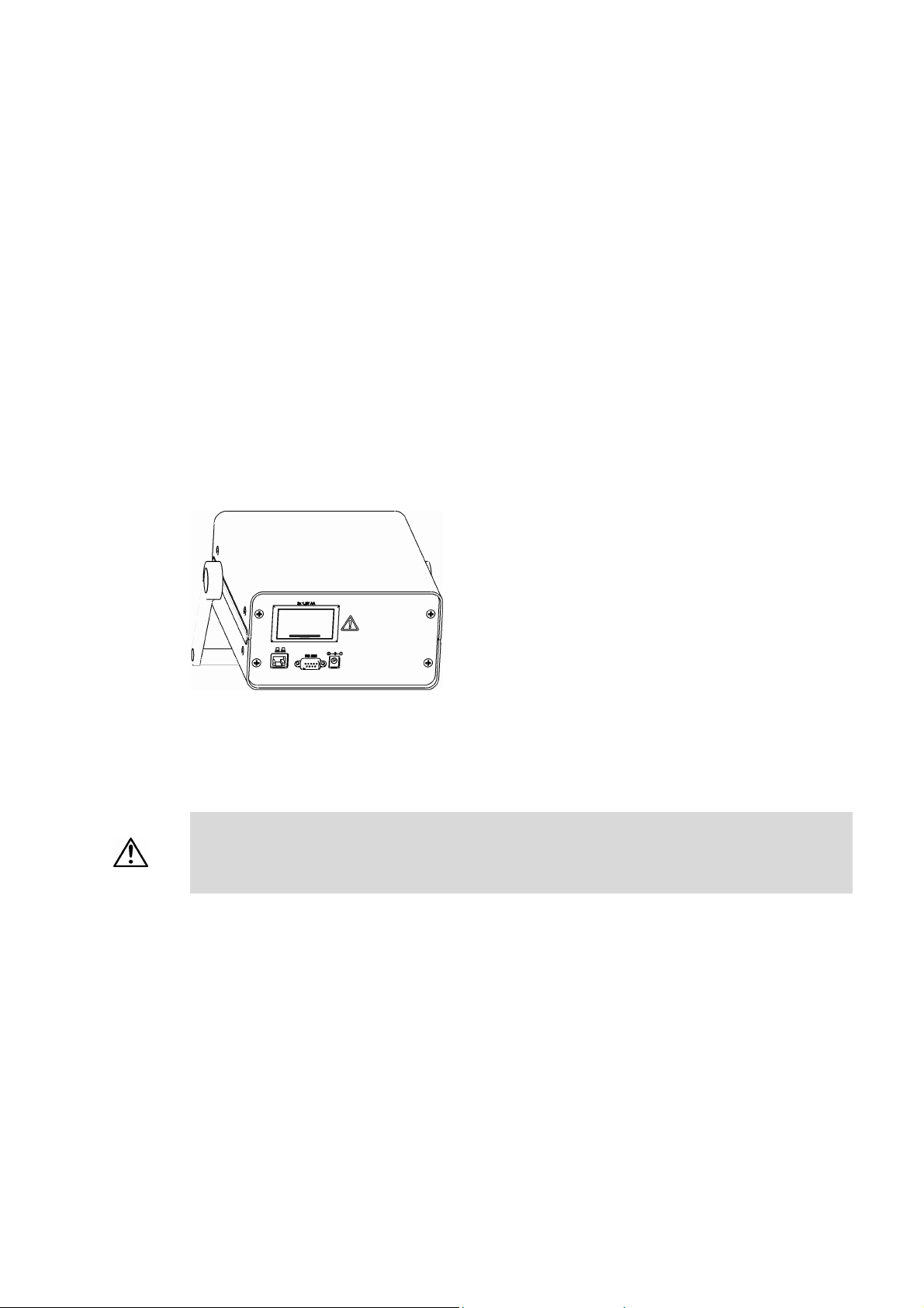
2.3 Safety Symbols on the Instrument
Fig. 2 – 1 Warning symbol next to the battery compartment
There is a warning sign on the rear of the instrument, next to the battery compartment.
Warning:
• Observe the correct polarity when placing the batteries.
• Only use 1.5 V AA batteries or 1.2 V AA rechargeable batteries of the same type and
charge condition.
Page 6 of 51
Page 7

TRUE TEMPERATURE
INDICATOR MODEL TTI-22
ISSUE 1 – 08/08
3. TTI-22 - An Overview
The TTI-22 measures temperatures in °C, K or °F with exceptional accuracy. Combined with
calibrated high-precision platinum resistance thermometers, TTI-22 allows a reduction of
system measurement uncertainties to an absolute minimum of as little as 1mK (0.001°C).
Connect TTI-22 to one or two Pt 100 industrial platinum resistance thermometers, whose
temperature is calculated according to DIN IEC751. Pt 25.5 or Pt 100 standard platinum
resistance thermometers are also suitable for use as temperature sensors. The temperature of
standard thermometers is calculated according to ITS-90 (International Temperature Scale
1990). Individual calibration parameters for up to 30 different sensors can be stored. This
provides easy recalibration and good traceability of the temperature measurement.
TTI-22 is operated via a menu-driven user interface. The current value, the mean value and
the standard deviation of 5 up to 50 values can be continuously displayed. The self-heating
effect of the sensor can be determined via the integrated self-heating test. TTI-22 has a serial
RS232 interface and an Ethernet terminal. The installed web server delivers all important data
to any given browser via internet or intranet.
Page 7 of 51
Page 8

TRUE TEMPERATURE
INDICATOR MODEL TTI-22
ISSUE 1 – 08/08
4. Checking the Supplied Parts
TTI-22 was tested and packed carefully before shipment. However, damages may occur
during transport.
1. Keep the packaging material (box, foam piece, transport protection) for possible
returns and further questions from the transport and insurance company.
2. Check the delivery for completion by comparing the supplied parts to those noted in
Table 4.1
3. If a part is missing, contact your Isotech representative.
4. If a part is damaged, contact the transport company and your Isotech representative.
Table 4.1: Supplied Parts
Pcs. Article Description
1 TTI-22
1 Instruction manual
1 RS232 cable
2 Lemo connectors to suit TTI-22
1 Mains Lead
1 Traceable calibration certificate
1 UKAS calibration certificate (optional extra)
1 Carrying case (optional extra)
1 Power supply
2 AA Batteries
Page 8 of 51
Page 9
TRUE TEMPERATURE
INDICATOR MODEL TTI-22
ISSUE 1 – 08/08
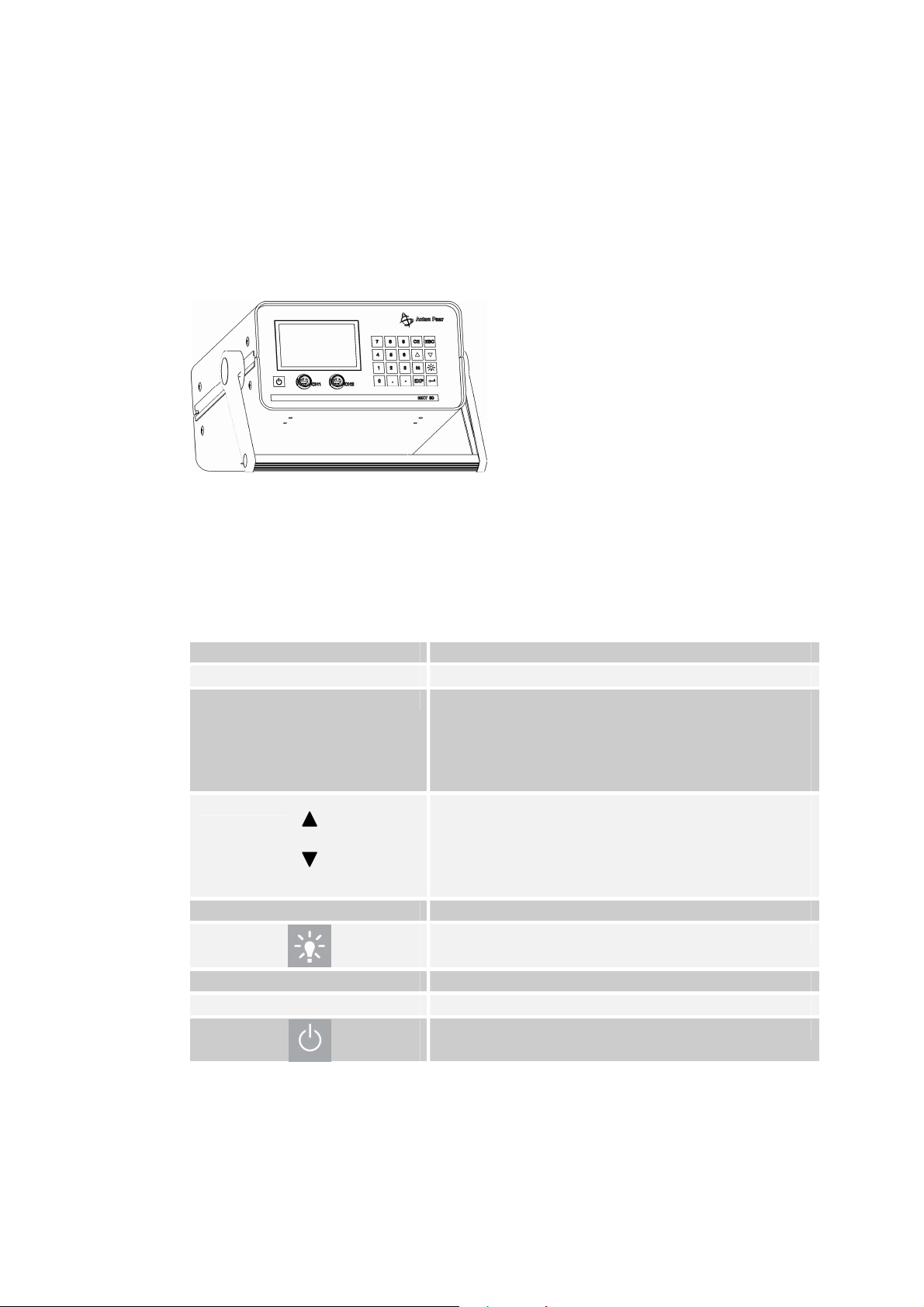
5. Operating Elements and Instrument Connections
5.1 TTI-22 Front Side
Fig. 5 – 1 Front view
5.1.1 Display and Function Keys
Function keys
0,1,2,.., 9 (numerical keys) Menu selection and digit input
CE (CLEAR, BACKSPACE) To delete the last entered character
ESC (ESCAPE) • In the menu mode: To change to the next higher
• To toggle between menu items or input fields
M (menu) To change from measurement mode to menu mode
EXP To enter the exponent of a number
(ENTER) To confirm the input
menu level
• In an active input field: To abort the input. The
input is cancelled and the prior field content is
restored
within one menu
• In statistics menus: To change the amount of
measuring values applied for calculating the
mean value and the standard deviation
Backlight On/Off
<On/Off> key
Page 9 of 51
Page 10
TRUE TEMPERATURE
INDICATOR MODEL TTI-22
ISSUE 1 – 08/08
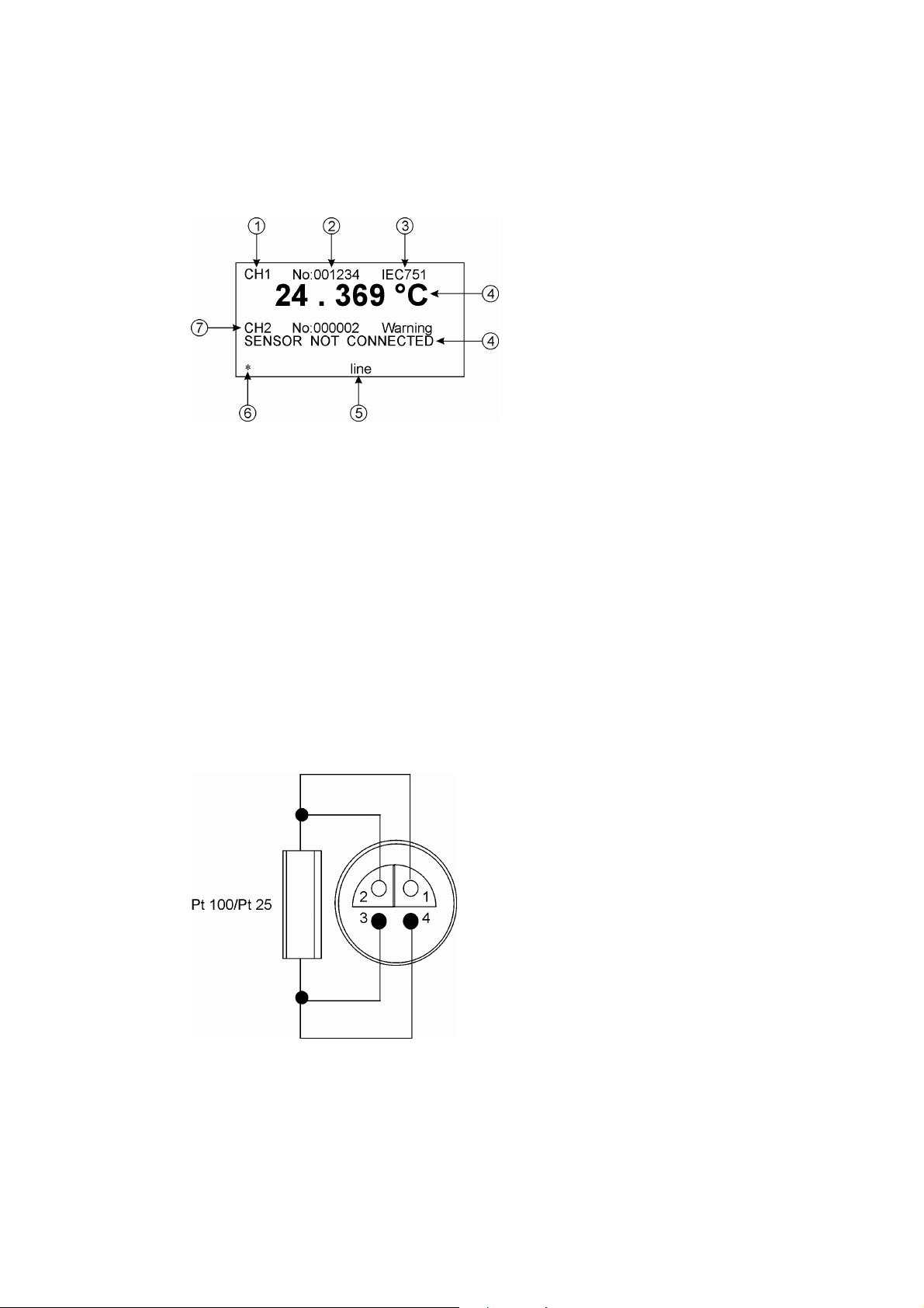
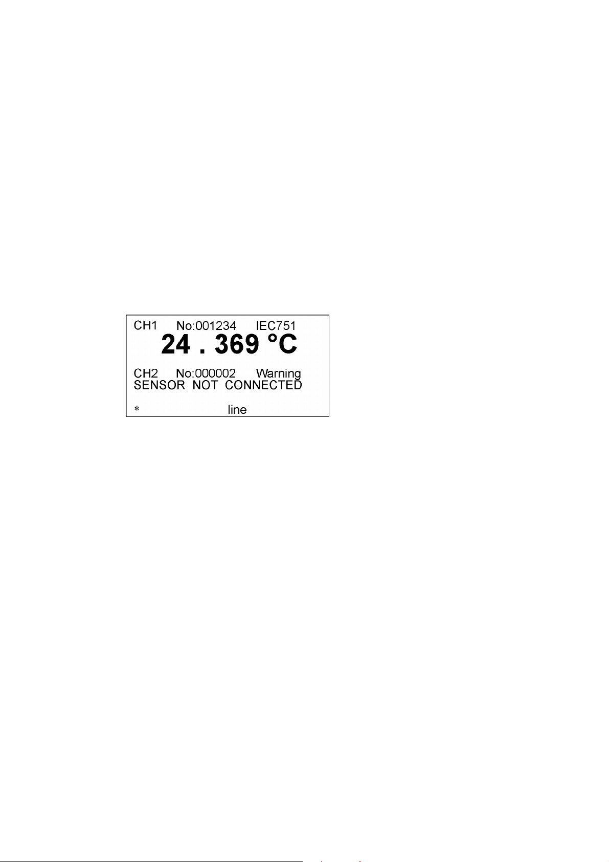
Display:
1 Sensor input 1 (channel 1)
2 Calibration number of sensor
3 Temperature calculation method or ‘Warning’
4 Temperature display or error message
5 Power supply
6 Symbol for measurement mode (blinking)
7 Sensor input 2 (channel 2)
Fig. 5 - 2 Example of a display
5.1.2 Instrument Connections on Front Side
You can connect up to two sensors to TTI-22 via 4-pole sockets (Fig. 5 - 1, "CH 1" and "CH
2") type LEMO 1S304.
Fig. 5 - 3 Assignment of LEMO socket
Page 10 of 51
Page 11
TRUE TEMPERATURE
INDICATOR MODEL TTI-22
ISSUE 1 – 08/08
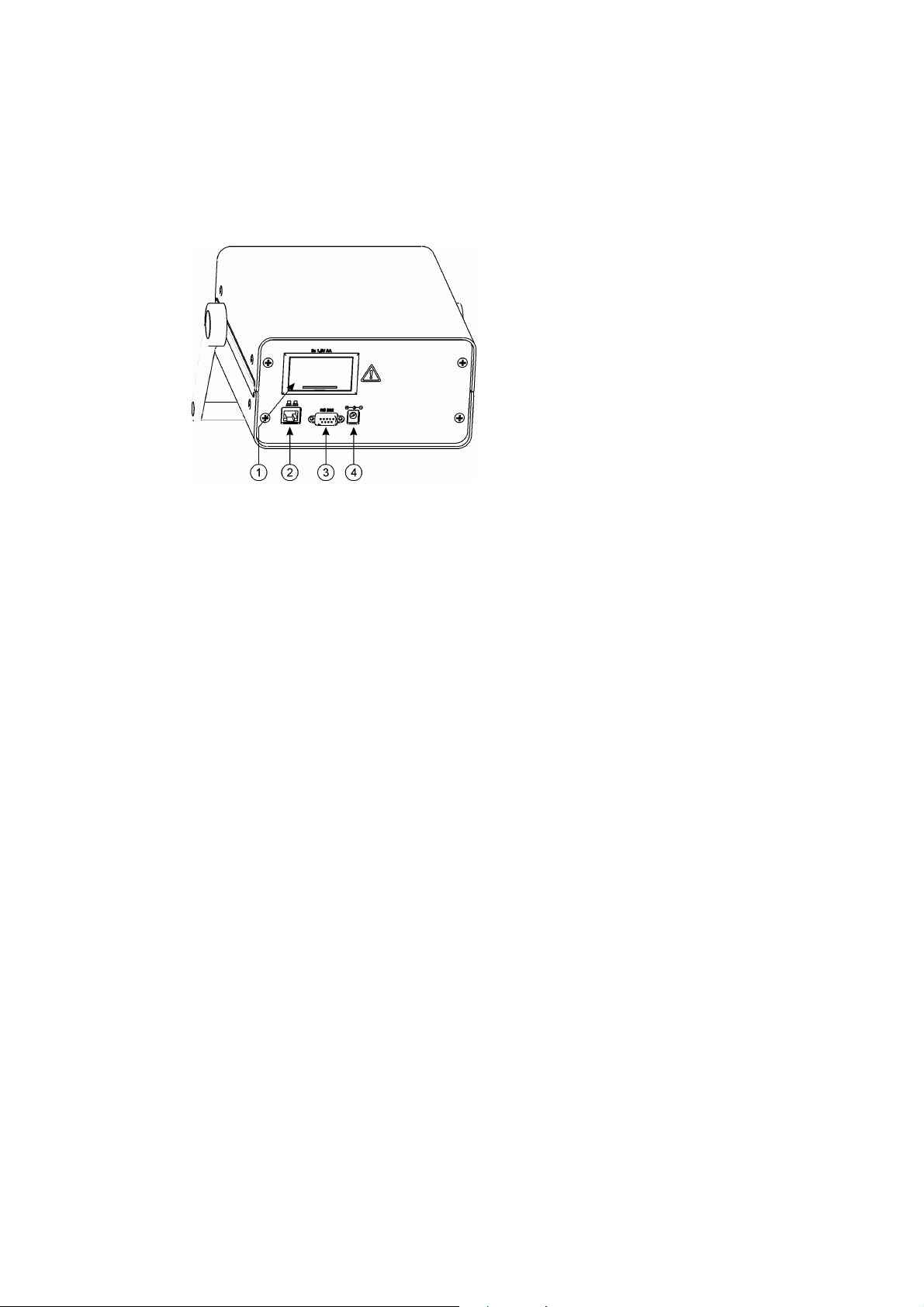
5.2 TTI-22 Rear Side
1 Battery compartment for two batteries type AA
2 Ethernet (LAN)
3 RS232 serial interface
4 Inlet for external power adapter
Fig. 5 - 4 Rear view
5.2.1 Terminal Assignment of RS232
Pin 1: not assigned
Pin 2: TXD (transmit data)
Pin 3: RXD (receive data)
Pin 4: not assigned
Pin 5: GND (ground)
Pin 6: not assigned
Pin 7: not assigned
Pin 8: not assigned
Pin 9: not assigned
5.2.2 Ethernet Terminal
The LAN terminal type RJ45 complies with the standard IEEE 802.3 (10 MBit).
5.2.3 External Power Adapter
Connect the delivered power adapter to the inlet (see (4) inlet for power adapter in Fig. 5 - 4).
The power supply is 7.5 V DC at a maximum of 3 A. As long as a power adapter is connected,
the batteries are not used.
Page 11 of 51
Page 12

TRUE TEMPERATURE
INDICATOR MODEL TTI-22
ISSUE 1 – 08/08
5.2.4 Battery Supply
Warning:
• Observe the correct polarity when placing the batteries.
Under typical operating conditions the delivered Alkaline cells run for approx. 10 hours. In
case of frequent battery usage, we recommend the use of rechargeable batteries for
environment protection.
The use of backlight, RS232 or the network cuts the battery runtime short. When using these
features, use batteries with large capacity (>2000 mAh).
Changing batteries
To open the lid of the battery compartment, stick a screwdriver into the mould and press the
lid down, away from the housing.
Observe the correct polarity when placing the new batteries (see sign in battery
compartment).
Charging batteries
Remove rechargeable batteries from the instrument for charging them.
• Only use 1.5 V AA batteries or 1.2 V AA rechargeable batteries of the same type and
charge condition.
Page 12 of 51
Page 13
TRUE TEMPERATURE
INDICATOR MODEL TTI-22
ISSUE 1 – 08/08
6. Putting TTI-22 into Operation
1. Check if the calibration numbers on these parts are identical:
- on the factory or UKAS calibration certificate
- directly at the sensor
- on the parameter printout, if existent ("Configuration Parameters")
2. Check if the serial number on TTI-22 (on the rear side of the instrument) matches the
number on the optional parameter printout ("Configuration Parameters").
3. If the above-mentioned numbers do not match, be sure to contact the manufacturer or
supplier of the instrument.
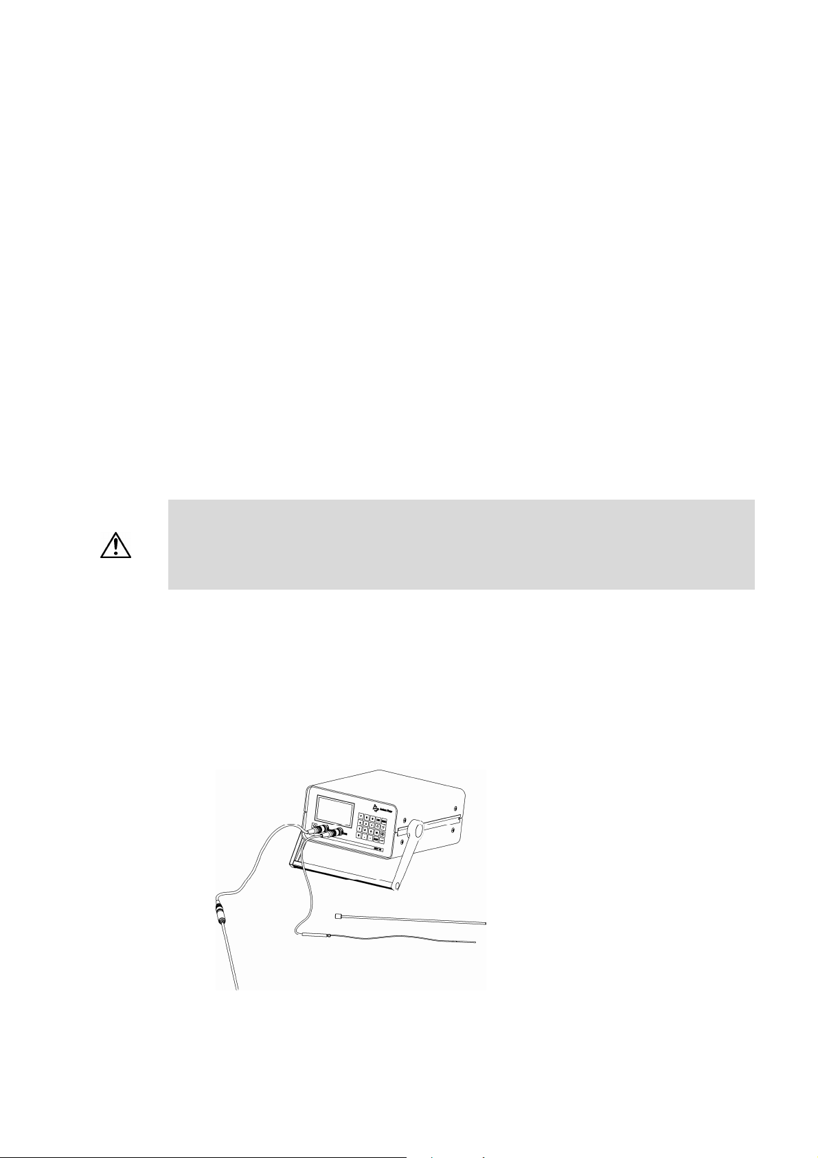
6.1 Assembling the Measuring System
Warning:
• Only use the delivered power adapter, Mat. No. 43768.
1. Place two 1.2/1.5V AA batteries in the battery compartment at the rear of the
instrument or connect the delivered power adapter.
2. If necessary, connect the sensor to the measuring cable (some sensors are supplied
with non-detachable cable).
3. Plug the sensor cable into the socket with the designation "CH 1" on the front side of
the instrument.
• Observe the correct polarity when placing the batteries.
• Only use 1.5 V AA batteries or 1.2 V AA rechargeable batteries of the same type and
charge condition.
Fig. 6 - 1 TTI-22 with connected sensors
Page 13 of 51
Page 14
TRUE TEMPERATURE
INDICATOR MODEL TTI-22
ISSUE 1 – 08/08
6.2 Putting the Measuring System into Operation
Press the <On/Off> key on the lower left front side of the instrument.
TTI-22 performs a self-test. If there are no errors, the instrument will enter measuring mode
after the self test.
6.2.1 Getting Started with Pre-stored Sensor Parameters
If sensor parameters have already been entered and assigned to the sensor inputs 1 and 2 ex
factory, TTI-22 displays the current temperature of the sensors.
Fig. 6 - 2 Example for a measurement display
1. Before measuring with TTI-22, check if the displayed sensor numbers "No”
match the numbers on the label positioned on the sensor.
2. Check if the entered and selected sensor parameters match the data on the factory or
UKAS calibration certificate (see Chapter 7.5).
Page 14 of 51
Page 15
TRUE TEMPERATURE
INDICATOR MODEL TTI-22
ISSUE 1 – 08/08
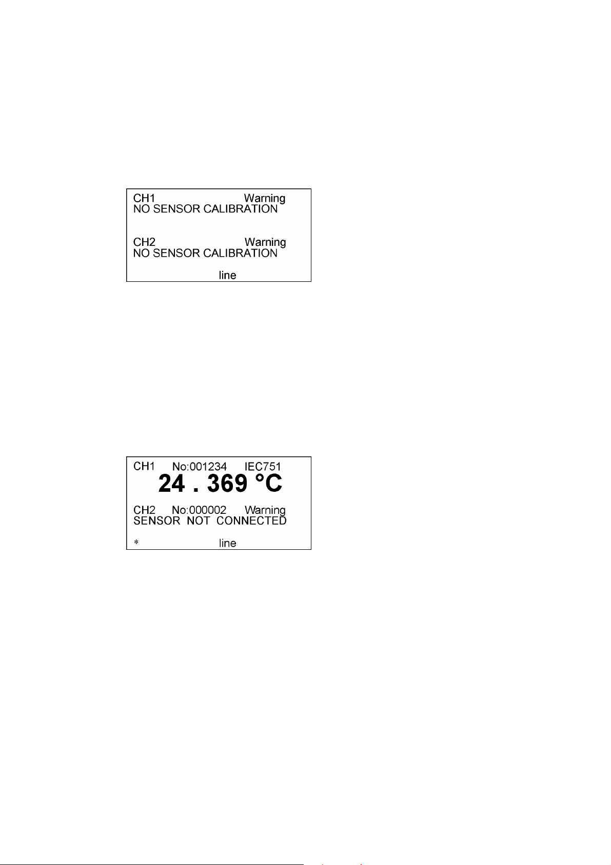
6.2.2 Getting Started without Stored Sensor Parameters
If no sensor parameters have been entered yet, TTI-22 displays no temperature:
Fig. 6 - 3 Display before input and/or selection of sensor parameters
You can either switch to the resistance display (see Chapter 7.6) or enter sensor parameters
and assign these to sensor inputs 1 and 2:
1. Enter the sensor parameters according to the calibration certificate (see
Chapter 7.5).
2. Assign the sensor parameters to the sensor input 1 (CH1) or 2 (CH2) (see
Chapter7.5)
TTI-22 displays the current temperature of the sensor:
Fig. 6 - 4 Display after input and selection of sensor parameters
6.2.3 Switching TTI-22 Off
If you switch off TTI-22 with the <On/Off> key, the current operating condition (e.g. mean
value mode for 20 values) is stored.
If you interrupt the power supply in another way, e.g. by pulling the plug, TTI-22 is
deactivated without storing the current operating condition.
1. To switch off TTI-22, change to measuring mode.
2. Keep the <On/Off> key pressed for 1-2 seconds.
TTI-22 displays the message "Power down" and switches itself off.
Page 15 of 51
Page 16
TRUE TEMPERATURE
INDICATOR MODEL TTI-22
ISSUE 1 – 08/08
7. Configuring TTI-22
After being switched on, TTI-22 is in measuring mode. Press the <M> key to change
to the menu mode.
There are two ways to select a menu item:
• Use the arrow keys to move the cursor to the desired item and press the <> key.
• Enter the digit in front of the menu item.
If the display does not provide enough space for all lines in a menu, the symbol for the arrow
key <> or <> appears on the right-hand side in the headline. You can scroll down the
display with these arrow keys.
To go back to the next higher level, press the <ESC> key.
To change back to the measuring mode, press the <ESC> key in the main menu.
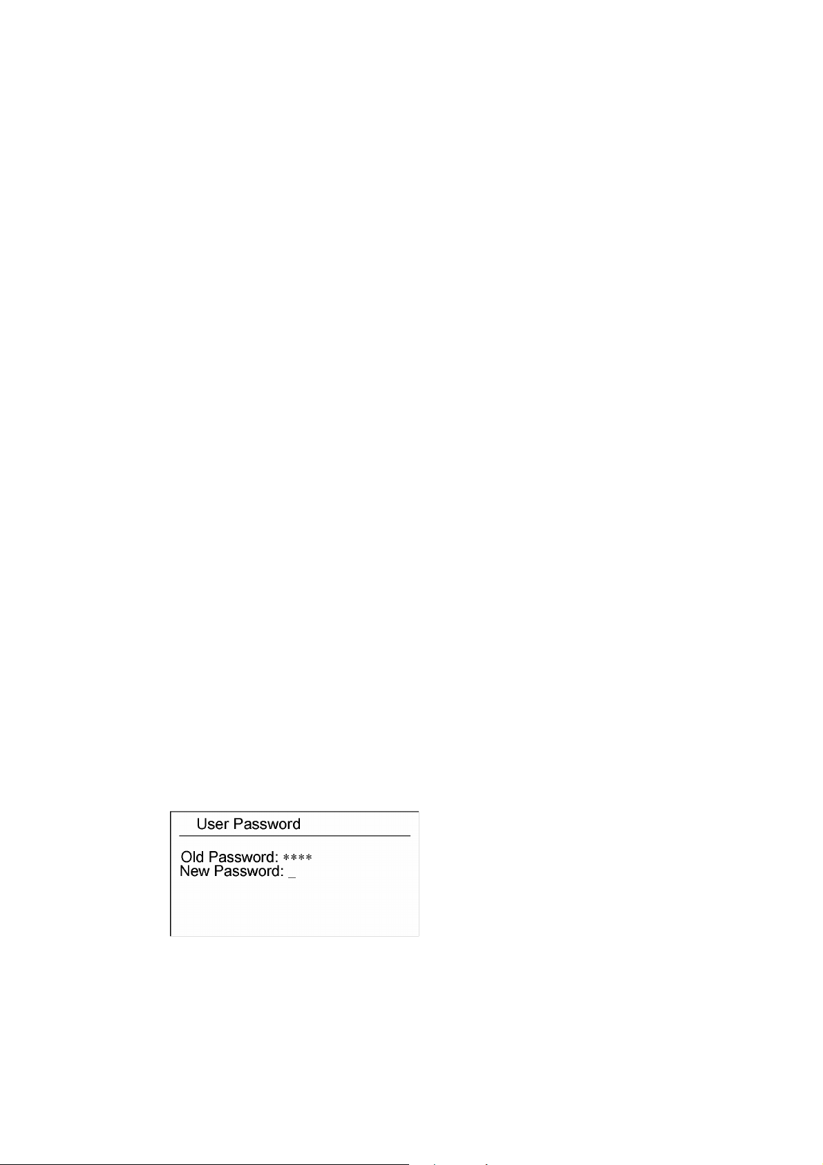
7.1 Setting a Password
TTI-22 has been assigned no password ex factory. We recommend setting a user
password as soon as possible.
The user password restricts the access to the menus Edit Configuration, Change User
Password and LOCK/UNLOCK Device.
To prevent unauthorized access to the menu, change to measuring mode before leaving the
instrument or switch TTI-22 off.
If you have forgotten your user password, contact your Isotech representative.
Setting a user password
Fig. 7 - 1 Setting or changing the user password
Page 16 of 51
Page 17

TRUE TEMPERATURE
INDICATOR MODEL TTI-22
ISSUE 1 – 08/08
1. Choose the menu 3 Change User Password.
2. Enter the old user password ("Old Password").
When setting a password for the first time, enter "0000" in this line and confirm with<>.
3. Enter a new user password ("New Password").
4. To save the new password, press the <> key and select the answer "1 YES" to the
question "Save changes?".
7.2 Setting Date and Time
The date and time are set in order to check the validity of a calibration.
• Date format: "DD.MM.YYYY" (Day.Month.Year)
• Time format: "HH.MM.SS" (Hour, Minute, Second)
1. To set the date and time, press the <M> key and switch to menu 2 Edit
Configuration > 1 Clock.
2. Press the <> key in order to enter the date and time via the numerical keys.
3. To change from day to month to year or to change from hour to minute to second,
press the <> key.
4. To exit the menu, press <ESC> and answer the question "Save changes?" with "1
YES".
7.3 Setting the Temperature Unit
To select the temperature display unit, switch to menu 2 Edit Configuration > 6 Units
& Backlight and set [°C], [K] or [°F].
Fig. 7 - 2 Temperature unit
Page 17 of 51
Page 18

TRUE TEMPERATURE
INDICATOR MODEL TTI-22
ISSUE 1 – 08/08
7.4 Setting Backlight and Contrast
1. To set the backlight, switch to menu 2 Edit Configuration > 6 Units & Backlight
> 2 Backlight.
Fig. 7 - 3 Setting backlight and contrast
In this menu you can set the backlight to be automatically activated (ON) or
deactivated (OFF) whenever TTI-22 is switched on.
During operation you can use the "Lamp" key to activate or deactivate the backlight at
will.
2. To set the contrast, select the menu item 3 Contrast and press <>. Each press of
the key changes the contrast level by 1 step.
7.5 Entering Sensor Parameters and Assigning to a Sensor Inlet
TTI-22 measures the electrical resistance of the connected platinum sensors and uses it to
calculate the temperature via internal formulas (standard case: quadratic equation).
These formulas’ coefficients, which are different for each sensor, are called sensor parameters
(or calibration parameters). Find these parameters in your calibration certificate.
Calibration parameters for up to 30 sensors can be stored in TTI-22.
Caution:
7.5.1 Entering or Changing Calibration Parameters for a Sensor
For each sensor you connect to the instrument you have to enter the calibration parameters
according to the calibration certificate in order to measure temperatures.
When performing a precise temperature measurement, only use calibrated sensors.
Page 18 of 51
Page 19

TRUE TEMPERATURE
INDICATOR MODEL TTI-22
ISSUE 1 – 08/08
Fig. 7 – 4 Entering, deleting and assigning calibration parameters
Caution:
1. Before entering the calibration parameters, make sure that the date stored in TTI-22 is
correct (see Chapter 7.2).
The date is stored together with the calibration parameters.
2. Switch to the menu mode and select the menu 2 Edit Configuration.
3. Enter the user password and then select the menu item 3 Sensors > 1 New/Edit
Calibr.
The calibration parameters of up to 30 sensors can be entered. Initially all 30 lines
display "--------- Free".
In the example in Fig. 7 - 5 calibration parameters for several sensors have already
been entered, with the sensor numbered "000001" having been assigned to channel 1
and the sensor numbered "125607" assigned to channel 2.
Make sure that you are using the correct calibration parameters for your sensors, since
incorrect calibration parameters lead to erroneous results.
Fig. 7 - 5 Display of menu item
4. Select the first line displaying "--------- Free" with the <> key.
Page 19 of 51
Page 20

TRUE TEMPERATURE
INDICATOR MODEL TTI-22
ISSUE 1 – 08/08
5. Select the temperature calculation method and/or the temperature range (see
Appendix D).
If the norm is not specified on the calibration certificate, you can use the calibration
parameters on the calibration certificate for differentiation. With DIN IEC 751 the
parameter R0 is always used, whereas with ITS-90 the parameter R(0.01 °C) is
specified.
• For industry sensors, e.g. the sensors described in Appendix G, select DIN
IEC 751.
• For standard thermometers select one of the 11 ranges of ITS-90.
6. Enter the calibration number Cal.No. written on the sensor and in the
calibration certificate.
7. Enter a calibration time Cal.Time according to your experience and/or accuracy
requirements.
Caution:
The calibration time mainly depends on the thermal stress on the platinum
thermometer. This calibration time can only be estimated and is decided by the user.
At the end of the calibration time the message "SENSOR CAL TIME" is displayed next
to the channel in question. No temperature is displayed.
The overtime exceeding the validity limit of the calibration is displayed in the menu
New/Edit Calibr. (e.g. "-14" means that the calibration has been invalid for 14 days).
In this case check the sensor either at a fixed point or by comparison calibration with a
reference thermometer.
8. If you have selected DIN IEC 75, set the calibration temperature range (e.g. –50 to 200
°C; 0 to 420 °C, etc.) in the lines Cal.Low and Cal.High.
9. Enter the maximum sensor temperature in the line Max.Temp.
If the sensor producer has not stated the maximum temperature, choose one that is
approx. 5°C above the upper limit (Cal.High) of the calibration temperature range.
Do not enter a value that is lower than the value entered for Cal.High. Otherwise the
maximum temperature limit is not monitored.
Therefore check your sensor including TTI-22 regularly (independent of the calibration
time) and after major thermal stress at the triple point or freezing point of water. We
recommend a yearly recalibration.
Caution:
Exceeding the permissible operation temperature range can cause irreversible change
in sensor behaviour and may require a new calibration.
Page 20 of 51
Page 21

TRUE TEMPERATURE
INDICATOR MODEL TTI-22
ISSUE 1 – 08/08
10. Enter the calibration parameters (R0, R[0.01 °C], A, B, C, C[1], ...C[5]) according
to the calibration certificate by overwriting the default values.
The number of parameters depends on the temperature range and the selected
temperature calculation method.
In IEC-751 the constant C is only used for temperatures below 0 °C. You can either
set "C" to "0" or use the default value.
11. After you have concluded your input, press <ESC> and save the new values.
Example for a Pt 100 sensor:
Cal. No.: 000001
Temp. Calculation: IEC-751
Validity of calibration: 180 days
Calibration temperature range: 0 - 200 °C
Maximum sensor temperature: 250 °C
R0 = 100.017
A = 0.0039126
B = -5.9153E – 7
After the example values have been entered, the display shows the following:
Fig. 7 - 6 Example for sensor data
After the maximum sensor temperature has been exceeded
1. Go to menu 3 Edit Configuration > 3 Sensors and select the item 1 New/Edit
Calibration.
The calibration of an "overheated” sensor is marked with "Max.Temp" in the field
"Cal.Time".
No temperature is displayed when this calibration is assigned to a sensor input, instead
the message "Max Temp. exceeded” is shown.
In order to use the calibration again, enter a positive number at "Cal.Time".
Page 21 of 51
Page 22

TRUE TEMPERATURE
INDICATOR MODEL TTI-22
ISSUE 1 – 08/08
2. Before continuing your work, at least check the sensor at the triple point or freezing
point of water.
The calibration parameters can only be used again if the deviation from the reference is
within the permissible range.
In most cases a new sensor calibration will be necessary, which means you are
provided new calibration parameters.
7.5.2 Assigning Calibration Parameters to a Sensor Channel
Assign a calibration to each of the two sensor channels (in menu 2 Edit Configuration > 3
Sensors > 3 Select Sensor #1 or 4 Select Sensor #2).
Information:
If you select the item "NO SENSOR Calibr." (the first line of the list on position 00) instead of
a valid sensor calibration, you receive no displays of temperature, only resistance values are
displayed.
7.5.3 Assigning Calibration Parameters to a Sensor Channel via PC/RS232
If you are using an external multiplexer or several calibrations for a sensor, you can assign a
stored calibration to the desired sensor input via PC. The PC-navigated assignment is lost
when the instrument is switched off. For connecting a PC, see Chapter 8.1.
To assign a calibration to a sensor input, send the command SET SEN1 XX/SET SEN2 XX
(XX = 01, ..., 30).
In the example, calibration 01 is assigned to sensor input 1 and calibration 03 is assigned to the
sensor input 2.
PC command TTI-22 response
SET SEN1 XX (e.g. XX = 01)
SET SEN2 XX (e.g. XX = 03)
SET SENSOR #1: 1
SET SENSOR #2: 3
7.6 Selecting Display Type
To set the display type, go to menu 1 Sel. Display & Start and select one of the 6 display types.
Fig. 7 - 7 Selecting the display type
Page 22 of 51
Page 23

TRUE TEMPERATURE
INDICATOR MODEL TTI-22
ISSUE 1 – 08/08
After this selection TTI-22 automatically goes back into measuring mode.
1 Resistance
Display of ohmic resistance with four digits after the decimal point.
2 Temperature
Display of temperature with three digits after the decimal point.
3 Resistance Stat.
Display of resistance statistics: Display of current resistance, mean value and standard deviation
of N previous values.
We recommend this display type for high-precision resistance measurements.
• Use the arrow keys to set the number N, the amount of values used for averaging,
between 5 and 50.
• After each change to the number N it takes N x 1.44 seconds until a new statistic is
displayed (see Fig. 7 - 8).
Fig. 7 - 8 Display of resistance statistic
The mean value and standard deviation are calculated using the following formulas:
Calculation of Mean:
N
RMean
1
==
N
∑
=
i
Rx
iMean
1
Calculation of empirical standard deviation S. Dev.:
N
..
N
∑
−
1
i
1
=
DevS
−
RRx
=
1
2
)(
Meani
Page 23 of 51
Page 24

TRUE TEMPERATURE
INDICATOR MODEL TTI-22
ISSUE 1 – 08/08
The standard deviation is a measure of the short-term stability of the measuring values and
should be lower than the expected measuring uncertainty.
4 Temperature Stat.
Display of temperature statistics: The current temperature is displayed with four digits after
the decimal point; the mean value and the standard deviation are displayed with five.
We recommend this display type for high-precision temperature measurements.
5 R1/RREF, R2/RREF
Display of the ratios of sensor resistance to internal reference resistance.
6 R1/R2, R2/R1
Display of the ratios of one sensor resistance to the other.
7.7 Performing a Self-heating Test
The term self-heating relates to the sensor being heated by the measuring current. The
measured temperature is therefore a bit higher than the temperature of the sample medium.
Errors through self-heating of approx. 2mK and higher can be determined with the self-heating
test.
Temperature changes of less than 0.5mK at operations with the lower measuring current are
within TTI-22’s measuring uncertainty and cannot be interpreted as self-heating.
Usually the self-heating of the sensor is considered in the calibration parameters. If the
measuring current during calibration strongly deviates from the measuring current in TTI-22,
or the thermal resistance (air, water, still or moving) strongly differs, this function is useful for
avoiding major errors. The self-heating of sensors that are supposed to measure the
temperature of still air, for example, is mostly already too significant to be ignored.
1. For the display select the temperature statistics (1 Sel. Display & Start > 4
Temperature Stat.).
2. Set N>20 and note the average temperature TempI.
3. Use the digit key <5> in the main menu to set Self.Heat.Test to On.
Now the measuring current is reduced times.
The lower right part of the display shows "SHT" for "Self Heating Test On"
4. Go back to the temperature statistics menu.
Page 24 of 51
Page 25

TRUE TEMPERATURE
INDICATOR MODEL TTI-22
ISSUE 1 – 08/08
5. Note the average temperature TempI/÷2 and calculate the temperature difference
(TempI - TempI/÷2).
6. Multiplying the determined temperature change by "2" gives you the current self-
heating of the sensor.
7. For the actual measurement switch back to Self.Heat.Test: Off.
Page 25 of 51
Page 26

TRUE TEMPERATURE
INDICATOR MODEL TTI-22
ISSUE 1 – 08/08
8. Reading out Measuring Data
You can transfer the measuring data to a PC. To do this, connect the PC to the RS232
interface of TTI-22 and use a terminal program or connect the PC to the Ethernet interface of
TTI-22 and use a web browser.
8.1 Transferring Measuring Data via RS232
For transferring the data, connect the RS232 interface on the rear side of TTI-22 with the
RS232 interface of the PC.
1. Connect the interfaces of TTI-22 and the PC with a data cable (e.g. a three-wire
shielded cable with the lines TXD, RXD and GND).
PC - SERIAL PORT
(9-PIN) RS232
1 Shield
2 (RXD) 2 (TXD)
3 (TXD) 3 (RXD)
5 (GND) 5 (GND)
Fig. 8 - 1 Interface connection
Caution:
The instruments earlier TTI-22 features another interface connection with the wires 2 (RXD)
and 3 (TXD) crossed. Therefore you cannot use the interface cable of these instruments for
TTI-22 unless you use an adapter which crosses RXD and TXD. We recommend using the
appropriate cable with the above specified interface connection (see Fig. 8 - 1).
2. Make sure that the interface parameters of TTI-22 and the PC match each other.
3. Configure the TTI-22 interface in the menu 2 Edit Configuration > 4 RS232
Config. as follows:
TTI-22
RS232
Fig. 8 - 2 Interface setting
4. Select the same interface settings in the terminal program on your PC as you set for
RS232.
Page 26 of 51
Page 27

TRUE TEMPERATURE
INDICATOR MODEL TTI-22
ISSUE 1 – 08/08
5. To request data, use your terminal program to send the according command to TTI-22
(see Table 8.1).
Each command consists of two words followed by a <CR> character (carriage return,
13hex), e.g. "GET DATA <CR>". Make sure that you set your terminal program
accordingly.
The response of TTI-22 consists of several lines separated by <CR> (carriage return)
and <LF> (line feed) (see Table 8.1).
If you have entered an incorrect command, TTI-22 responds to the PC by sending
back the available commands (see Appendix C.2).
Table 8.1: PC Commands
PC command transfered data, examples
GET DATA
GET RREF
GET SENSOR
18.12.07 17:38:30
R1= +125.02085 Ohm
R2= +109.00070 Ohm
T1= +64.6448 C
T2= +23.1107 C
SENSOR1= No:000002
SENSOR2= No:000001
RREF Calibration:
INT. RREF = 380.009068
CAL TIME (DAYS): 364
Sensor Calibrations:
Sensor 1 = N:000002
IEC751
CAL TIME (DAYS): 29
MAX TEMP[*C]: 990
CAL LOW[*C]: -300
CAL HIGH[*C]: 990
R0: 100.0000000
A: 0.00390802
B: -5.802000E-07
C: -4.273500E-12
Sensor 2 = N:000001
IEC751
CAL TIME (DAYS): 29
MAX TEMP[*C]: 250
CAL LOW[*C]: 0
CAL HIGH[*C]: 200
R0: 100.0000000
A: 0.00390802
B: -5.802000E-07
C: -4.273500E-12
Page 27 of 51
Page 28

TRUE TEMPERATURE
INDICATOR MODEL TTI-22
ISSUE 1 – 08/08
Table 8.1: PC Commands
PC command transfered data, examples
GET CONFIG
Configuration:
Software V1.000
18.12.07 17:43:03
RREF Calibration:
INT. RREF = 380.009068
CAL TIME (DAYS): 364
Sensor 1 = N:007833
IEC751
CAL TIME (DAYS): 100
MAX TEMP[*C]: 800
CAL LOW[*C]: -50
CAL HIGH[*C]: 200
R0: 100.0000000
A: 0.00390830
B: -5.577500E-07
C: -4.183000E-12
Sensor 2 = N:007845
IEC751
CAL TIME (DAYS): 100
MAX TEMP[*C]: 800
CAL LOW[*C]: -50
CAL HIGH[*C]: 200
R0: 100.0000000
A: 0.00390830
B: -5.577500E-07
C: -4.183000E-12
Sensor 3 = N:000001
IEC751
CAL TIME (DAYS): 29
MAX TEMP[*C]: 250
CAL LOW[*C]: 0
CAL HIGH[*C]: 200
R0: 100.0000000
A: 0.00390802
B: -5.802000E-07
C: -4.273500E-12
Sensor 5 = N:000419
ITS-90 0-419*C
CAL TIME (DAYS): 30
MAX TEMP[*C]: 990
CAL LOW[*C]: 0
CAL HIGH[*C]: 420
R.01: 100.0000000
A: 0.00030000
B: -9.000000E-04
Page 28 of 51
Page 29

TRUE TEMPERATURE
INDICATOR MODEL TTI-22
ISSUE 1 – 08/08
Table 8.1: PC Commands
PC command transfered data, examples
GET RSTAT
R1= 108.98370 Ohm
Mean= 108.98418 Ohm
S.Dev= 0.00026 Ohm
R2= 125.02094 Ohm
Mean= 125.02093 Ohm
S.Dev= 0.00003 Ohm
GET TSTAT
SENSOR1= No:000002
T1= +23.0535 C
Mean= 23.05659 C
S.Dev= 0.00183 C
SENSOR2= No:000001
T2= +64.6449 C
Mean= 64.64503 C
S.Dev= 0.00013 C
GET STATUS
TTI-22 atus
MAC: 000DD9010764
Mains supply
8.2 Transferring Measuring Data via Ethernet
For data transfer connect the Ethernet interface (LAN) of TTI-22 to a local network.
Caution:
1. Configure the Ethernet interface at TTI-22 in the menu 2 Edit Configuration > 5
Ethernet Config as follows:
Be sure to only enter configuration parameters that fit the network you use. If necessary,
contact the network administrator.
Fig. 8 - 3 Ethernet interface setting
The required IP address, Netmask (NM) and Gateway (GW) can be obtained from
your network administrator.
Page 29 of 51
Page 30

TRUE TEMPERATURE
INDICATOR MODEL TTI-22
ISSUE 1 – 08/08
The MAC address (Media Access Control) is the unique address of the instrument and
was already entered ex factory.
2. To request data, enter the IP address in your browser.
The temperature and resistance values will be displayed. Currently no further
functions are available.
Page 30 of 51
Page 31

TRUE TEMPERATURE
INDICATOR MODEL TTI-22
ISSUE 1 – 08/08
9. Calibrating and Adjusting TTI-22
TTI-22 uses an internal reference resistor for measuring the electrical resistance of the sensor.
The temperature value is calculated from the resistance measurement via internal formulas.
For a precise temperature calculation a regular calibration/adjustment of TTI-22 and the used
sensor is necessary.
Send TTI-22 to Isotech once a year for calibration/adjustment. For further information contact
your local Isotech representative.
If you have the capacities for performing a calibration yourself, see Appendix E.
Page 31 of 51
Page 32

TRUE TEMPERATURE
INDICATOR MODEL TTI-22
ISSUE 1 – 08/08
10 Locking Calibration Parameters
With a second password, the "Lock-Password", you can lock parts of the menu so that the
relevant settings for the temperature measurement can no longer be manipulated. In this way,
for example, standards bureau officers can lock TTI-22 for temperature measurements
requiring official calibration.
After the Lock password has been entered, the menu items 1 to 3 in the submenu 2 Edit
Configuration are locked. Sensor parameters and reference resistor parameters and the time
and date can no longer be altered.
Entering Lock password
1. Enter the user password.
2. Choose menu 4 LOCK Device.
3. Enter a Lock password.
Now TTI-22 is locked. In the main menu 4 UNLOCK Device is displayed.
In locked condition, the date, time, reference resistor parameters and sensor
parameters can be accessed, but not altered.
4. To unlock TTI-22, select the menu 4 UNLOCK Device and enter the Lock password.
Now TTI-22 is unlocked. In the main menu 4 LOCK Device is displayed.
Lock password forgotten
If you have forgotten the Lock password, contact your Isotech service engineer.
This engineer can unlock TTI-22. Then you have to define a new Lock password.
Page 32 of 51
Page 33

TRUE TEMPERATURE
INDICATOR MODEL TTI-22
ISSUE 1 – 08/08
11. Overview of the Menu Structure
Fig. 11 - 1 Menu structure
11.1 Main Menu
Fig. 11 - 2 Main menu
1 Sel. Display & Start Display type selection.
2 Edit Configuration Instrument parameter setting.
3 Change User Passw. Entering/changing user password.
4 LOCK Device Locking or unlocking TTI-22 with a "Lock Password".
5 Self.Heat.Test: OFF Switching on/off the self-heating test.
Page 33 of 51
Page 34

TRUE TEMPERATURE
INDICATOR MODEL TTI-22
ISSUE 1 – 08/08
11.2 Sel. Display & Start (Display Type Selection)
Fig. 11 - 3 Menu for display type selection
1 Resistance Display of ohmic resistances with four digits after the decimal
point
2 Temperature Display of temperatures with three digits after the decimal
point
3 Resistance Stat. Display of resistance statistics: Display of resistances, mean
values and standard deviations of the N last values. N can be
set with the arrow keys.
4 Temperature Stat. Display of temperature statistics: The current temperatures
are displayed with four digits after the decimal point, the mean
values and the standard deviations are displayed with five.
5 R1/RREF, R2/RREF Display of the ratios of sensor resistance to reference
resistance in large digits.
6 R1/R2, R2/R1 Display of the ratios of the two sensor resistances in large
digits.
11.3 Edit Configuration
Fig. 11 - 4 Menu for setting the configuration
1 Clock For setting the date and time. Date format "DD.MM.YYYY"
(Day.Month.Year)
Time format: "HH.MM.SS" (Hour, Minute, Second)
2 Reference Resistor
1 Edit Int. RRef For entering or changing the reference resistor value and the
calibration time.
2 Adj. Int. RRef Automatic calibration of the internal reference resistor.
Page 34 of 51
Page 35

TRUE TEMPERATURE
INDICATOR MODEL TTI-22
ISSUE 1 – 08/08
3 Sensors
1 New/Edit Calibr. For entering or editing sensor parameters. Up to 30
calibrations can be stored in TTI-22.
Cal.No. Calibration number.
Cal. Time Calibration time in days: Period of a calibration’s validity.
Max. Temp. Maximum permissible temperature (if unknown, use Cal.
High+ 5 °C).
Cal. Low Calibration temperature range.
Cal. High
(only for IEC 751)
R0, R.01 Calibration parameters: Resistance value at "0" or "0.01" °C,
A, B, C coefficients of the used formulas
C[1], ... C[5]
2 Delete Calibr. For deleting sensor parameters.
3 Select Sensor#1 For assigning sensor parameters to a sensor input (CH1 or
CH2).
4 Select Sensor#2
4 RS232 Config. Interface parameters of RS232.
5 Ethernet Config. Parameters for the LAN interface.
6 Units & Backlight
1 Units: °C/°F/K For choosing degrees Celsius (°C), Kelvin (K) or degrees
Fahrenheit (°F) as temperature display unit.
2 Backlight: OFF/ON In this menu you can set the backlight to be automatically
activated whenever TTI-22 is switched on. During operation
you can use the "Lamp" key to activate or deactivate the
backlight at will.
3 Contrast For setting the contrast (20 ... 41).
Page 35 of 51
Page 36

TRUE TEMPERATURE
INDICATOR MODEL TTI-22
ISSUE 1 – 08/08
Appendix A: Technical Data
The following specifications are related to an ambient temperature of +23 °C.
Find these terms explained in Basic Terms in Metrology 1319 Part 1-3.
A.1 TTI-22 as High-precision Resistance Meter
Internal reference resistance: approx. 380 Ω
Resistance measuring range: approx. 0-440 Ω
Resolution (0.1 ppm f.s.a): 40 µW
Linearity error (< 1 ppm f.s.): < 0.4 mW
Measuring uncertaintyb: < 0.4 mW
(confidence level: 95 %,
Number of measuring values: 50)
a
f.s. = full scales
b
This value does not include the calibration uncertainty of the used reference number.
A.2 TTI-22 as High-precision Thermometer (Specifications without
Sensor)
Pt 100, DIN IEC 751
Temperature measuring range: -200 °C to 850 °C
(depending on sensor)
Resolution: 0.1 mK
Linearity error (< 1 ppm f.s.a): < 1 mK
Measuring uncertainty b: < 1 mK
(confidence level: 95 %,
Number of measuring values: 50)
Sensor: Platinum sensor up to a resistance of 440Ω
a
f.s. = full scales
b
This value does not include the calibration uncertainty of the used reference number.
Page 36 of 51
Page 37

TRUE TEMPERATURE
INDICATOR MODEL TTI-22
ISSUE 1 – 08/08
A.3 General Instrument Data
Measuring current (IDC): 0.5 mA
Measuring current (Ieff):
Normal operation: 0.41 mA
41.0
During self-heating test: 0.29 mA
= 29,0
2
Self-heating test on: Measuring current/÷2
Measuring time: 1.44 seconds
(complete, for both channels)
Internal reference resistor:
Producer, type: VISHAY, VHP 101
Temperature coefficient: < 0.3 ppm/°C (+15 to +25 °C)
Stability without strain
(producer information): 5 ppm max. dR after 1 year
10 ppm max. dR after 3 years
Display: Liquid Crystal Display, graphic, with LED
backlight 128 64 points (approx. 6.5 * 3.5 cm)
Keyboard: 20 keys
Number of sensor inlets (channels): 2
Sensor connections: two Lemos sockets size 1S304, four-pole
Data outlets: RS232 D (9-pole D-Sub outlet)
LAN/Ethernet (RJ 45 plug)
Ambient conditions: 0 -35 °C,
no direct exposure to sunlight
< 90% air humidity, non-condensing
Warm-up time: 60 minutes
Power supply:
Batteries/rechargeables: 2x 1.2-1.5 V AA
or power adapter (Mat. No. 43768): Input: AC 100 - 240 V, 50 - 60 Hz, 2 W
Output: DC 7.5 V, 250 mA
Dimensions (L x W x H): 240 x 190 x 110 mm
(without handle)
Weight approx. 2 kg
Page 37 of 51
Page 38

TRUE TEMPERATURE
INDICATOR MODEL TTI-22
ISSUE 1 – 08/08
Appendix B: Declaration of Conformity
Page 38 of 51
Page 39

TRUE TEMPERATURE
INDICATOR MODEL TTI-22
ISSUE 1 – 08/08
Appendix C: Troubleshooting
C.1 TTI-22 Error Messages
If errors occur during TTI-22 operation, an error message is displayed.
Error message Cause Correction
"ADC ERROR
OUT OF
RANGE"
"CALIBRATION
RANGE"
"MAX TEMP
EXCEEDED"
"NO SENSOR
CALIBRATION"
"RREF CAL.
TIME"
"SENSOR CAL.
TIME"
"SENSOR NOT
CONNECTED"
"WRONG RREF
SELECTION"
The sensor is damaged or the TTI22 ADC is defective.
• The sensor parameters were
entered incorrectly or with a
wrong algebraic sign.
• The temperature range
entered (IEC751) or selected
(ITS-90) at the sensor
parameters was underrun or
overrun.
The sensor was heated to a
temperature higher than the
maximum entered in the
calibration data.
"Max.Temp." is displayed in the line
"Cal.Time".
No sensor parameters were
assigned to the channel.
The calibration time of the
reference resistor is over. A
negative digit is displayed in the line
"Cal.Time".
The calibration time of the
selected sensor is over. A negative
digit is displayed in the line
"Cal.Time".
No sensor was connected to the
sensor channel.
The actual value of the reference
resistor differs too much from the
entered value.
Contact your Isotech
representative or apply a different
sensor.
• Check the entered
parameters.
• Assign another calibration
with appropriate temperature
range to the sensor channel.
Calibrate the sensor again and
enter the new calibration
parameters.
Assign sensor parameters to the
channel.
Calibrate the reference resistor
and enter a positive digit at
"Rref:CALTIME".
Calibrate the sensor and enter the
new calibration parameters
(including the calibration time).
Connect a sensor.
Calibrate TTI-22 again and enter a
precise value.
Page 39 of 51
Page 40

TRUE TEMPERATURE
INDICATOR MODEL TTI-22
ISSUE 1 – 08/08
C.2 PC Error Messages
If TTI-22 is connected to a PC via RS232 interface and data is read out with a terminal
program, the PC may receive the following error messages.
Error message Cause Correction
??? UNKNOWN
COMMAND
COMMANDS:
GET DATA
GET RREF
GET SENSOR
GET CONFIG
GET RSTAT
GET TSTAT
GET STATUS
SET SEN1
SET SEN2
The entered command was not
recognized.
Be sure to use the correct syntax.
After entering "GET RSTAT" or "GET TSTAT":
"Too few samples" The mean and standard deviation
values are directly requested after
starting up TTI-22 or after changing
the number "N" before the number
of measuring values "N" is reached
"wrong display
mode selected"
TTI-22 is not in the correct statistics
display mode.
When choosing a sensor calibration with the command "SET SEN1 XX" or "SET
SEN1 XX":
"invalid memory
number"
"no calibration
data"
"too few
A value outside the range from 1 to
30 was entered as XX.
There is no data for the selected
sensor calibration.
The XX value has not been entered. To choose a calibration, use the
parameters for
SET SEN"
"R1 = not valid" Answer to the command "Get Data"
if the calibration of the internal
reference resistor has expired.
"T1 = not valid" Answer to the command "Get Data"
if the calibration of the measuring
sensor has expired or the maximum
temperature has been exceeded.
Wait N x 1.44 seconds before
reading out the result.
Set the correct display mode.
To choose a calibration, use the
correct syntax "SET SEN1 XX" or
SET SEN2 XX" (XX = 01, ..., 30).
Choose a different sensor calibration
or extend the calibration data of the
chosen sensor calibration.
correct syntax "SET SEN1 XX" or
SET SEN2 XX" (XX = 01, ..., 30).
Adjust the internal reference
resistor.
Renew the calibration of the sensor.
Page 40 of 51
Page 41

TRUE TEMPERATURE
INDICATOR MODEL TTI-22
ISSUE 1 – 08/08
C.3 Problems with Instrument Activation
If TTI-22 cannot be switched on or immediately switches itself off again after activation, check
the following:
1. If you operate TTI-22 with batteries/rechargeables, check their charge condition.
2. If you operate TTI-22 with a power adapter, check whether the power adapter is
correctly plugged in.
3. If the instrument immediately switches itself off despite functional power supply, check
the sensors:
• Disconnect the sensors from TTI-22.
• Switch on the instrument.
If it is switched on without problems, the error is caused by a defect of the sensor or
sensor cable.
• Repair the sensors or sensor cables or exchange them.
Page 41 of 51
Page 42

TRUE TEMPERATURE
INDICATOR MODEL TTI-22
ISSUE 1 – 08/08
Appendix D: Temperature Calculation Methods
TTI-22 employs two methods for calculating the temperature from the primarily measured property "ohmic
resistance": The DIN IEC 751, which describes the relation between resistance and temperature for industrial
sensors, and the ITS-90 (International Temperature Scale 1990), the temperature scale valid for standard
thermometers since 1990.
D.1 DIN IEC 751: Industrial Platinum Resistance Thermometers and
Platinum Measuring Resistors
The DIN IEC 751 defines requirements for industrial platinum resistance thermometers whose
electrical resistance is a defined function of the temperature. It is valid for platinum
thermometers in the temperature range of -200 °C to +850 °C.
Basic values
The relation between electrical resistance and temperature is defined as follows:
Range -200 °C to 0 °C:
(Equ. 1) Rt = R0[1 + At + Bt2 + C(t - 100 °C)t3]
Range 0 °C to 850 °C:
(Equ. 2) Rt = R0(1 + At + Bt2)
Constants: Variables:
A = 3.9083 x 10⁻³ °C-1 t…..Temperature in °C
B = -5.775 x 10⁻⁷ °C-2 Rt…Resistance at temperature t
C = -4.183 x 10⁻¹² °C-4 R0…Resistance at 0°C
The basic values for platinum resistance thermometers are calculated from the equations (1)
or (2).
Nominal values
The nominal value for platinum resistance thermometers usually is 100 Ω (at 0 °C).
Page 42 of 51
Page 43

TRUE TEMPERATURE
INDICATOR MODEL TTI-22
ISSUE 1 – 08/08
Limiting deviations
Two classes of resistance thermometers are discerned based on their limiting deviations:
Class Limiting deviations in °C
A 0.15 + 0.002 * |t|a
B 0.3 +0.005 * |t|
Calibration of industrial platinum resistance thermometers
Example:
Rt = R0[1 + At + Bt2]
the parameters R0, A and B are determined.
a
|t|…Absolute numerical value of the temperature in °C
Thermometers with a nominal value of 100 Ω have to be classified based on the limiting
deviations.
Class A cannot be used for Pt 100 above 650 °C and thermometers with 2-wire connection of
the sensor.
The equations and constants defined in DIN IEC 751 are used to classify sensors with regard to
their highest permissible deviations. In this way, DIN sensor replacement without any on-site
calibration is possible.
Uncalibrated sensors are not suitable for high-precision temperature measurements – at 0 °C
they already feature an allowed deviation of several tenths of degrees Celsius.
Thus, new solutions were called for. Based on many years of experience, it was found that
industrial sensors with a considerably higher accuracy (10mK) over a wide temperature range
can be produced and calibrated.
To achieve this accuracy, the sensors have to be compared to reference thermometers at
three or four certain temperatures. The equation used in DIN IEC 751 for determining the
basic values is then set to these measuring points. This gives individual parameters R0, A, B
and/or C for each sensor.
You require a platinum resistance thermometer for the range of 0-200 °C. The thermometer is
compared to a high-precision reference thermometer at 0 °C, 100 °C and 160 °C. With the
three measuring points and the equation
For calibration plausibility the calibrated platinum resistance thermometer is compared to the
reference thermometer at 60 °C too. From the correlation of the temperatures at this point
the measuring uncertainty of the thermometer between the calibration points can be
determined.
Page 43 of 51
Page 44

TRUE TEMPERATURE
INDICATOR MODEL TTI-22
ISSUE 1 – 08/08
A sensor calibrated in this manner together with a TTI-22 can achieve measuring uncertainties
of <10mK in the calibrated range.
The total measuring uncertainty largely depends on the calibration of the sensor; the measuring
uncertainty of the high-precision thermometer TTI-22 is negligible.
D.2 International Temperature Scale 1990 (ITS-90)
11 temperature ranges of ITS-90 are implemented in the instrument. Find further details on
this temperature scale in technical literature.
Table 11.1: Calibration points and parameters for the temperature ranges 1 through 4 (in K) (T
... triple point)
Temperature range
[K]
1 13,8033 - 273,16 TH2, TNe, TO, THg, TH2Oa a, b, c1, c2, c3, c4, c5
2 24,5561 - 273,16 TH2, TNe, TO, TAr, THg,
3 54,3584 - 273,16 TO, TAr, THg, TH2O a, b, c1
4 83,8058 - 273,16 TAr, THg, TH2O a, b
a.. and additional temperatures close to 17 K and 20.3 K
Table 11.2: Calibration points and parameters for the temperature ranges 5 through 11 (in °C)
(T ... triple point, E ... freezing point, S ... melting point)
Temperature range
[°C]
5 0 - 961,78 TH2O, ESn, EZn, EAl, EAg a, b, c, d (d = 0 for T90
6 0 - 660,32 TH2O, ESn, EZn, EAl a, b, c
7 0 – 419.527 TH2O, ESn, EZn a, b
8 0 – 231.928 TH2O, EIn, ESn a, b
9 0 – 156.5985 TH2O, EIn a
10 0 – 29.7646 TH2O, SGa a
11 -38.8344 – 29.7646 THg, TH2O, SGa a, b
Calibration points Parameters
a, b, c1, c2, c3
TH2O
Calibration points Parameters
< 660.323 °C), W (660 °C)
Page 44 of 51
Page 45

TRUE TEMPERATURE
INDICATOR MODEL TTI-22
ISSUE 1 – 08/08
Appendix E: Calibrating and Adjusting TTI-22
E.1 Calibrating and Adjusting TTI-22
During calibration the displayed temperature value or resistance value is compared to the
display of an accurate reference thermometer or reference resistor. The deviation from the
reference is determined.
During the adjustment the instrument parameters are set in such a way that the deviation from
the reference is as small as possible.
Caution:
The absolute accuracy of the resistance/temperature measurement depends on the
calibration and subsequent adjustment of TTI-22.
The highly stable high-precision resistor VHP 101 from the company VISHAY is installed as
internal reference resistor in TTI-22. Its specifications are as follows:
- Long-term stability at storage conditions: 5 ppm per year (1 % A.Q.L.)
- Temperature coefficients of the resistor: < 0.3 ppm/°C (-55 to 125 °C)
The internal reference resistor is barely strained during laboratory use, neither thermally nor
electrically (dissipation loss 100 µW). So these are practically storage conditions.
Determining suitable calibration intervals
If the true value of the reference resistor deviates from the value stored in TTI-22, this will
result in a gain error of the resistance measurement in the used measuring model. If the
deviation is 3 ppm, for example, the additional deviation of the sensors’ resistance display also
is 3 ppm.
The resulting systematic deviation of the temperature display approximately stems from the
absolute error of the resistance display divided by 0.1 mOhm/mK (Pt 25) or 0.4 mOhm/mK (Pt
100). Therefore this systematic deviation of the temperature display depends on the range.
• Therefore only let well-trained staff or an authorized institute perform the calibration
and adjustment.
• Record each calibration and adjustment in writing and file these records with care.
Caution:
Before the instrument is delivered, the value of the internal reference resistor is determined
to four digits after the decimal point and is stored in the instrument. To ensure the absolute
accuracy of the resistance/temperature measurement, do not change the numerical value of
the reference resistor without prior recalibration.
Page 45 of 51
Page 46

TRUE TEMPERATURE
INDICATOR MODEL TTI-22
ISSUE 1 – 08/08
Calculation example:
Measuring instrument: TTI-22, RRef = approx. 380W, max. aging per year
5ppm
Sensor: Pt 100, R1 = 100 Ω (relates to approx. 0 °C)
Relative deviation of the
resistance display: 5 ppm
Absolute deviation of the
resistance display: 5 ppm * 100 Ω = 0.5 mW
Resulting deviation of the
temperature display: 0.5 mW/(0.4 mW/mK) = 1.25mK (after 1 year)
If the additional systematic deviation throughout the entire measuring range is supposed to be
smaller than 1mK, the change of the reference resistance can amount to a maximum of 1ppm.
The internal reference resistor has to be calibrated every two months.
In case of a limited measuring range or a lower accuracy requirement, the calibration intervals
can be increased accordingly. After the repeated calibration of the internal reference resistor
over a period of 1 to 2 years its behaviour can be predicted with great accuracy.
Performing an automatic adjustment
You can adjust the internal reference resistor very easily by connecting an exactly known,
certified standard resistor and determining the new value of the internal reference resistor.
Equipment:
- TTI-22
- Standard resistor [100 Ohm or rather 400 Ohm]
- Calibration certificate for the standard resistor certified by a bureau of standards
[measuring uncertainty < 1 ppm]
- Thermostat with oil bath
1. The standard resistor in the oil bath needs to be brought to the reference temperature
stated in the calibration certificate.
2. Connect the standard resistor to sensor channel 1.
3. Select the menu item 2 Edit Configuration > 2 Reference Resistor > 2 Adj. Int.
RRef.
Fig. E – 1 Adjusting reference resistor
Page 46 of 51
Page 47

TRUE TEMPERATURE
INDICATOR MODEL TTI-22
ISSUE 1 – 08/08
4. At Std. Res enter the standard resistor value according to the calibration certificate.
5. Now press the <> key.
6. Wait approx. 1.5 minutes (50 measuring values).
The newly determined value of the internal reference resistor New Rref as well as the
old value Old Rref appear on the display.
7. Note the old and the new reference resistor values and the current date.
8. File these records with care.
9. To continue, press the <> key.
10. Press the <> key again in order to store the new value for the internal reference
resistor.
The calibration time Cal.Time is automatically set to 100 days. You can individually
customize the calibration time.
Caution:
After the adjustment, perform another calibration to check TTI-22 as follows:
11. Choose menu 1 Sel. Display & Start > 3 Resistance Stat.
12. Use the <> key to set the amount of values N, with which the mean value is
calculated, to 50.
13. Wait approx. 1.5 minutes.
14. Check if the displayed mean value of the standard resistor accords with the mean value
stated in the calibration certificate.
The two values shall at most differ by the measuring uncertainty of TTI-22.
The calibration time can only be estimated. Therefore it is your own responsibility to
perform regular checks of the measuring device at the triple point or freezing point of water.
Page 47 of 51
Page 48

TRUE TEMPERATURE
INDICATOR MODEL TTI-22
ISSUE 1 – 08/08
Performing a manual adjustment
For a manual adjustment, as opposed to the automatic one, you need to calculate the new
value of the internal reference resistor and enter it into TTI-22 yourself.
The following formula is used for the calculation:
R
=
[ ] [ ]
oldfnewf
ReRe
R
R
R
calculated value of the internal reference resistor in Ω
Ref[new]
value of the internal reference resistor stored in TTI-22 in Ω
Ref[old]
value of the externally connected standard resistor in Ω according to
ext
calibration certificate
Ran mean value of the external standard resistor displayed on TTI-22 (amount of
the measuring values used for averaging: N=50)
Equipment:
- TTI-22
- Standard resistor [100 Ω or 400 Ω]
- Calibration certificate for the standard resistor certified by a bureau of standards
[measuring uncertainty < 1 ppm]
- Thermostat
1. Find the value for RRef[old] in the menu 2 Edit Configuration > 2 Reference
Resistor > 1 Edit Int. RRef.
2. Find the value Rext in the calibration certificate of the standard resistor.
3. To determine the value Ran, the standard resistor in the thermostat needs to be
brought to the reference temperature stated in the calibration certificate.
4. Connect the standard resistor to sensor channel 1.
5. Choose menu 1 Sel. Display & Start > 3 Resistance Stat.
6. Use the <> key to set the amount N, with which the mean value is calculated, to
50.
7. After approx. 1.5 minutes, read the mean value Ran from the display.
8. Insert the determined values in the formula and in this way calculate the new value of
the internal reference resistor RRef[new].
9. Save the new value of the reference resistor in TTI-22 via the menu 2 Edit
Configuration >2 Reference Resistor > 1 Edit Int. RRef.
ext
(Equ. 3)
xRR
R
an
Page 48 of 51
Page 49

TRUE TEMPERATURE
0185
.
100
INDICATOR MODEL TTI-22
ISSUE 1 – 08/08
10. Now check if the displayed mean value of the external standard resistor accords with
the mean value stated in the calibration certificate.
11. Note the date, measuring medium and RRef[new] in a measuring protocol and file it
with care.
Example:
R
R
according to calibration certificate) = 100.014 Ω
Ran (displayed value on TTI-22) = 100.0185 Ω
As this shows, the displayed value deviates from the actual value stated in the calibration
certificate. Insertion in Equ. 3 gives:
(stored in TTI-22) = 400.003 Ω
Ref[old]
(value of the externally connected standard resistor
ext
RexRnewf
[ ]
003.400
014.100
Ω== 9850.399
After the new value 99.9985 Ω has been entered for RRef, the mean value displayed on TTI 22 has to match the actual value of the standard resistor.
Otherwise repeat the procedure.
E.2 Calibrating and Adjusting the Sensor
You can calibrate and adjust sensors by connecting a known, certified reference sensor and
your un-adjusted sensor to a TTI-22 unit and in this way determining the value of the sensor
resistance using a highly precise thermostat at various temperatures. With equations of DIN
IEC 751 or ITS-90 you can calculate the sensor parameters.
Equipment:
- TTI-22 (adjusted)
- Reference sensor with calibration certificate
- Un-adjusted sensor
- Thermostat
1. Connect the reference sensor to sensor channel 1.
2. Connect the un-adjusted sensor to sensor channel 2.
3. Select the display type Resistance Stat.
4. Read the values for the resistance.
5. Calculate the coefficients with the according formula.
6. Record the calibration and adjustment data in writing and file these records with care.
7. Enter the newly calculated coefficients for your sensor into TTI-22 and assign these
calibration parameters to a sensor input.
Page 49 of 51
Page 50

TRUE TEMPERATURE
[][
]
+°=
INDICATOR MODEL TTI-22
ISSUE 1 – 08/08
Appendix F: Converting the Temperature Unit
To convert the temperature into different units, use the following conversion equations:
Conversion of degrees Fahrenheit:
5
[ ] [ ]
[ ] [ ]
Conversion of Kelvin:
[ ] [ ]
δ
[ ] [ ]
( )
FKT
δ
9
5
( )
δ
9
9
( )
5
KTCt
32.
−°=°
FCt
KTF
15.273
−=°
15.27332.
+−°=
3215.273.
+−=°
Conversion of degrees Celsius:
CtKT
[ ] [ ]
δ
T[K] ..... Temperature in K
t[°C] .... Temperature in °C
d[°F] .... Temperature in °F
9
5
15.273
32.
+°=°
CtF
Page 50 of 51
Page 51

TRUE TEMPERATURE
INDICATOR MODEL TTI-22
ISSUE 1 – 08/08
Appendix G: Firmware Versions
Firmware version Date of release Comment
V1.04T 06-2008 First Public released firmware version.
Page 51 of 51
 Loading...