

Page 1
Instruction Manual
SLM 52N
Sound Level Meter
FREN
IT
DE
ES
Un Ov
Page 2

CONTENTS
Title Page
1. INSTRUMENT CARE.....................................................................................1
2. FEATURES.....................................................................................................2
3. MEASUREMENT PARAMETERS..................................................................2
4. SPECIFICATIONS..........................................................................................2
5. CONTROLS AND FUNCTIONS.....................................................................9
6. DISPLAY DESCRIPTION............................................................................. 11
7. PREPARATION FOR USE...........................................................................12
8. CALIBRATION PROCEDURE.....................................................................14
9. MEASUREMENT PROCEDURE..................................................................14
10. STORE OPERATIONS...............................................................................15
11. OUTPUT CONNECTORS...........................................................................16
12. ADJUSTMENT DATA FOR CALIBRATOR (B&K TYPE 4226 PRESSURE
MODE)........................................................................................................16
13. TYPICAL INSTRUMENT FREQUENCY RESPONSE AT 0° INCIDENCE.16
14. TYPICAL FREQUENCY RESPONSE DUE TO CASE REFLECTIONS AT 0°
INCIDENCE.................................................................................................17
15. TYPICAL FREQUENCY RESPONSE OF 65mm WINDSCREEN AT 0°
INCIDENCE ................................................................................................17
16. DIRECTIONAL CHARACTERISTICS OF THE COMPLETE INSTRUMENT
..........................................................................................................................18
17. APPENDIX A FREQUENCY WEIGHTING NETWORK.............................20
18. APPENDIX B RMS DETECTION CIRCUIT AND TIME WEIGHTING.......21
19. APPENDIX C INFLUENCE OF BACKGROUND NOISE ..........................23
Page 3

EN-1
1. INSTRUMENT CARE
Do not attempt to remove the mesh cover from the microphone as this will cause
damage and affect the accuracy of the instrument.
Protect the instrument from impact. Do not drop it or subject it to rough handling.
Transport it in the supplied carrying case.
Protect the instrument from water, dust, extreme temperatures, high humidity and
direct sunlight during storage and use.
Protect the instrument from air with high salt or sulphur content, gases and stored
chemicals, as this may damage the delicate microphone and sensitive electronics.
Always turn the instrument off after use. Remove the batteries from the instrument if
it is not to be used for a long time. Do not leave exhausted batteries in the
instrument, as they may leak and cause damage.
Clean the instrument only by wiping it with a soft, dry cloth or, when necessary, with
a cloth lightly moistened with water. Do not use any solvents, alcohol or cleaning
agents.
Page 4

EN-2
2. FEATURES
The ISO-TECH SLM 52N Sound Level Meter complies with the requirements of
IEC 61672-1: 2002 standard for a Class 2 instrument.
The instrument contains several features which permit sound level measurements
under a variety of conditions.
Features include:
Ease of use.
Easy to read large display.
Five measurement ranges.
Fast and Slow time weightings.
A and C frequency weightings.
Both AC and DC signal outputs are available from a single standard 3.5mm
coaxial socket suitable for use with a frequency analyzer, level recorder, FFT
analyzer, graphic recorder, etc.
3. MEASUREMENT PARAMETERS
The following parameters are used on the instrument.
LA → “A” frequency weighting sound pressure level
LC→ “C” frequency weighting sound pressure level
FAST→Fast time weighting
SLOW→Slow time weighting
max → Maximum time-weighted sound pressure level
The various settings depend on the condition the instrument was in before it was last
turned off.
4. SPECIFICATIONS
Specifications apply to Model SLM 52N fitted with Microphone model MC-21 and
Microphone Preamplifier model AP-21
Applicable standards:
IEC61672-1: 2002 Class 2
IEC60651: 1979 Type 2
ANSI S1.4: 1983 Type 2
Page 5
EN-3
Measurement functions:
•
Main processing functions
Sound level: Current time-weighted sound pressure level A or current timeweighted sound pressure level C
Maximum time-weighted sound pressure level A or Maximum time-weighted
sound pressure level C
•
Total range
: 30 to 130dB A & C weighted
•
Max. measurement level
: 130dB
•
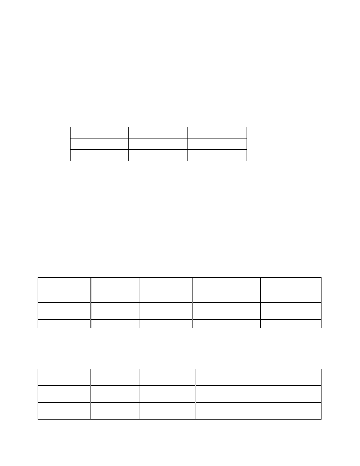
Self-generated noise level:
Typical values at 23℃ using the nominal microphone equivalent capacitance of 27pF
(30-90dB range)
Weighting Electrical Total
“A” 22.7dB 26.1dB
“C” 21.8dB 29.5dB
Linearity operating range
: A-weighted, 1000Hz, 60dB dynamic range.
Total linear operating range:
In accordance with IEC 61672-1, A-weighted, 1000Hz: 30dB to 130dB.
Level range selection
:
5 ranges in 10dB steps 30 to 90dB , 40 to 100dB
50 to 110dB , 60 to 120dB
70 to 130dB
LINEAR OPERATING RANGES (L.O.R.)
RANGE: 30 – 90 dB. Test starting point 64 dB for all weightings and frequencies except
31.5Hz A-weighted, for which the starting point is 44 dB.
FREQUENCY
Hz
WEIGHTING L.O.R.
dB
WEIGHTING
L.O.R.
dB
31.5 A 36.1 – 50.6 C 39.5 – 87.0
1000 A 36.1– 90.0 C 39.5 – 90.0
4000 A 36.1 – 90.0 C 39.5 – 89.2
8000 A 36.1 – 88.9 C 39.5 – 87.0
RANGE: 40 – 100 dB. Test starting point 74 dB for all weightings and frequencies except
31.5Hz A-weighted, for which the starting point is 54 dB.
FREQUENCY
Hz
WEIGHTING L.O.R.,
dB
WEIGHTING
L.O.R
dB
31.5 A 40.0 – 60.6 C 40.0 – 97.0
1000 A 40.0 – 100.0 C 40.0 – 100.0
4000 A 40.0 – 100.0 C 40.0 – 99.2
8000 A 40.0 – 98.9 C 40.0 – 97.0
Page 6
EN-4
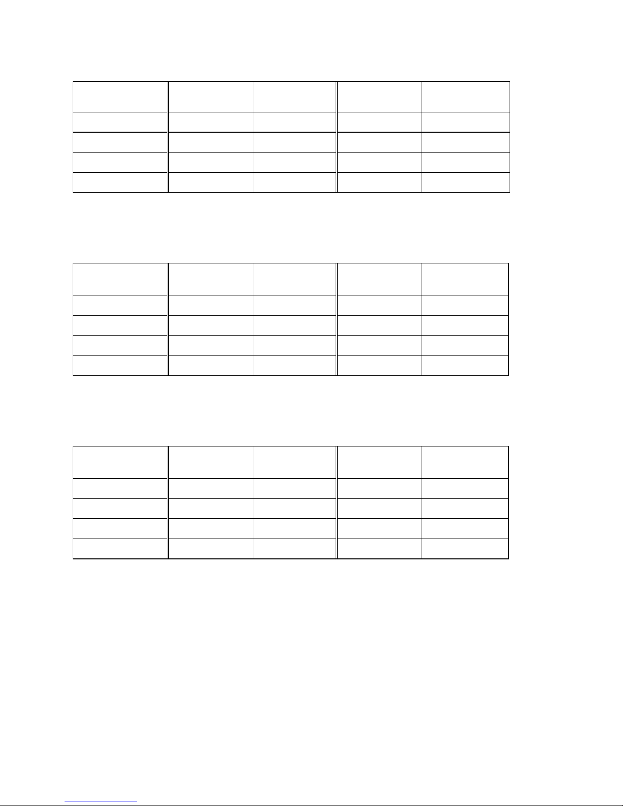
RANGE: 50 – 110 dB. Test starting point 84 dB for all weightings and frequencies except
31.5Hz A-weighted, for which the starting point is 64 dB.
FREQUENCY
Hz
WEIGHTING
L.O.R
dB
WEIGHTING
L.O.R
dB
31.5 A 50.0 – 70.6 C 50.0 – 107.0
1000 A 50.0 – 110.0 C 50.0 – 110.0
4000 A 50.0 – 110.0 C 50.0 – 109.2
8000 A 50.0 – 108.9 C 50.0 – 107.0
RANGE: 60 – 120 dB. Test starting point 94 dB for all weightings and frequencies except
31.5Hz A-weighted, for which the starting point is 74 dB.
FREQUENCY
Hz
WEIGHTING
L.O.R.
dB
WEIGHTING
L.O.R.
dB
31.5 A 60.0 – 80.6 C 60.0 – 117.0
1000 A 60.0 – 120.0 C 60.0 – 120.0
4000 A 60.0 – 120.0 C 60.0 – 119.2
8000 A 60.0 – 118.9 C 60.0 – 117.0
RANGE: 70 – 130 dB. Test starting point 104 dB for all weightings and frequencies
except 31.5Hz A-weighted, for which the starting point is 84 dB.
FREQUENCY
Hz
WEIGHTING
L.O.R.
dB
WEIGHTING
L.O.R.
dB
31.5 A 70.0 – 90.6 C 70.0 – 127.0
1000 A 70.0 – 130.0 C 70.0 – 130.0
4000 A 70.0 – 130.0 C 70.0 – 129.2
8000 A 70.0 – 128.9 C 70.0 – 127.0
Frequency range
:
Overall characteristics including microphone: 31.5 to 8000Hz
Frequency weighting: A,
meets the requirement of IEC 61672-1 for class 2
“A” weighting.
C,
meets the requirement of IEC 61672-1 for class 2
“C” weighting.
Time weighting (RMS detection): Fast
, according to IEC 61672-1 class 2.
Slow
, according to IEC 61672-1 class 2.
Page 7

EN-5
•
Reference conditions:
Type of the acoustic field:
Free
Reference sound pressure level:
94.0dB (related to 20µPa)
Reference level range:
60 to 120dB
Reference frequency:
1000Hz
Reference temperature:
+23
℃
Reference relative humidity:
50%RH
Reference static pressure:
101.325 kPa
Reference incidence direction:
Perpendicular to the front of the microphone
diaphragm.
•
Calibration:
Acoustic using calibrator ISO-TECH SLC 1356, B&K 4231 or equivalent.
Calibration check frequency is 1000Hz.
Nominal calibration level for the free field:
94.1dB
Nominal calibration level for the diffuse field:
94.0dB
•
Frequency for acoustic testing:
8000Hz
.
•
Warm-up time:
≦
2min
•
Sampling interval:
Bar graph indication → 125 ms approx.
Numeric indication → 1 sec approx.
•
Microphone equivalent electrical impedance (electrical input device) :
Replace
the microphone capsule with a series capacitance of 27pF +/- 3pF
Microphone:
•
Model:
MC-21
•
Nominal diameter:
1/2 inch electret condenser type
•
Sensitivity:
-37dB (0dB = 1V/Pa)
•
Frequency response:
31.5Hz to 8000Hz
•
Capacitance:
27pF
•
Reference direction and position:
Perpendicular to the front of the microphone
diaphragm at its geometric centre.
•
Maximum input sound level:
131dB at microphone for no damage.
•
Operating temperature:
-10°C to +50°C
•
Temperature coefficient:
Approx. 0.008dB/°C at 1000Hz
•
Dimensions:
13.2dia x 14mm
Page 8
EN-6
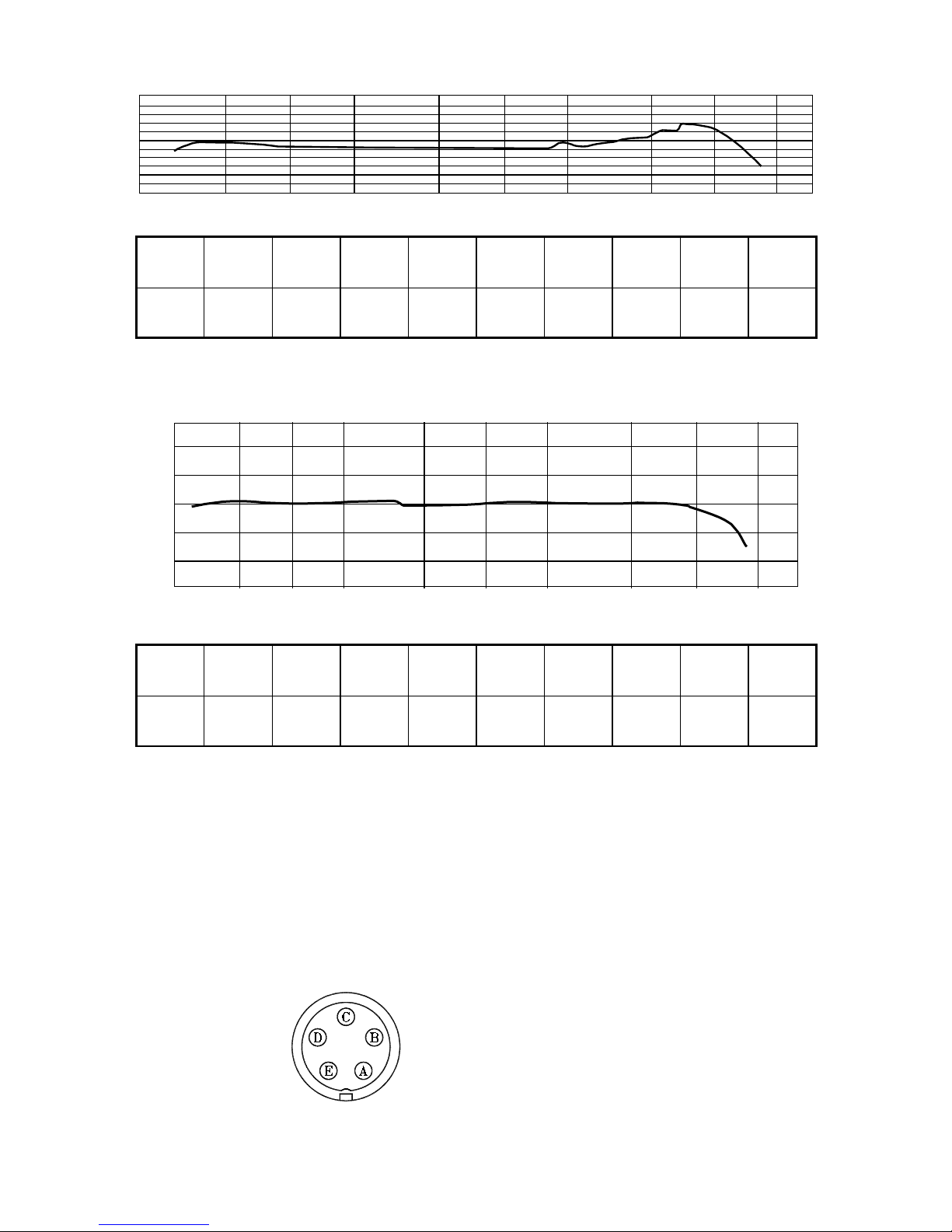
Frequency Response
+5
-5
20 50 100 200 500 1000 2000 5000 10000 20000 (Hz)
(
dB)
0
Freq
units
31.5
Hz
63
Hz
125
Hz
250
Hz
500
Hz
1000Hz2000Hz4000Hz8000
Hz
dB +0.6 +0.8 +0.2 +0.0 0.0 0.0 +0.8 +1.3 +3.0
Typical free-field response 0°°°° incidence
2
0
-
2
0
-10
0
1
0
2
0
(
d
B
)
5
0
1
0
0
2
0
0
5
0
0
1
0
0
0
2
0
0
0
5
0
0
0
1
0
0
0
0
2
0
0
0
0
(
H
z
)
Freq
units
31.5
Hz
63
Hz
125
Hz
250
Hz
500
Hz
1000Hz2000Hz4000Hz8000
Hz
dB +0.1 +0.4 0.0 +0.5 -0.2 0.0 +0.2 0.0 -0.5
Typical diffuse-field response for random incidence
Preamplifier:
•
Model:
AP-21
•
Input impedance:
470MΩ
•
Output impedance:
550Ω at 1000Hz
•
Maximum input voltage:
2.828V peak-to-peak at electrical input for no damage.
•
Measuring input (viewed from top of instrument):
A: ground
B: ground
C: +10V
D: signal input
E: N.C.
Page 9

EN-7
Display LCD
•
Display screens
:
4 digit numerical indication of sound level, from 30.0 to 130.0dB with 0.1dB
resolution.
Bar-graph indication of current sound level with 1dB resolution.
Sound level range indicator: 30–90dB, 40–100dB, 50–110dB, 60–120dB or
70–130dB in five ranges.
Memory and Read indicator : 99 sets
•
Display update rate:
1 second
•
Display first indication:
Depends on the condition the instrument when it was last
turned off.
•
Warning indications:
Out-of-range indications:
Ov displayed at upper limit of the range
Un displayed at lower limit of the range
Outputs
•
AC output
(using selected frequency weighting)
Output voltage:
1Vrms (at full-scale of the range)
Output impedance:
5k
Ω
Load impedance:
≧
1M
Ω
•
DC output
Output voltage:
10mV/dB
Output impedance:
5k
Ω
Load impedance:
≧
1M
Ω
Power requirements
•
One 9V battery (006P or IEC6F22) manganese super heavy duty batteries or
equivalent.
•
Battery life
: Approx. 25 hours
•
External power source:
DC voltage from 6V to 12V
Current rating:
Approx. 10mA @ 6V
Ambient conditions:
•
Environmental conditions
: 23°C, 50%RH and 101.325 kPa
•
Operating conditions
: -10°C to +50°C, 30% to 90%RH non-condensing
•
Storage conditions
: -10°C to +60°C, <70%RH non-condensing
•
Effect of temperature:
< 0.5dB (-10 to +50°C)
•
Effect of humidity:
< 0.5dB (for 30%RH to 90%RH at 40°C, 1000Hz)
•
Effect of vibration:
A 40 Hz 1m/s vibration produces no noticeable effect.
•
Effect of magnetic field:
No noticeable effect.
Page 10

EN-8
Compliance with standards:
•
:
indicates compliance with applicable European Union Directives.
•
EMC Emission
: IEC 61000-6-3, Generic emission standard for residential,
commercial and light industrial environments.
No significant emissions from the instrument.
IEC 61672-1, Instrumentation standard classification group X and
performance class 2 sound level meter.
•
EMC Immunity
: IEC 61000-6-2, Generic standard-Immunity for industrial
environments.
No degradation in performance when subjected to 10V/m for 80%
modulation at 1KHz.
IEC 61672-1, Instrumentation standard classification group X and
performance class 2 sound level meter.
No permanent degradation of performance, loss of function,
change of operating state or configuration, or loss or corruption of
stored data due to ESD discharges as specified in the above
standard.
•
No degradation in performance when the instrument was subjected to ESD at 8kV
per IEC 801-2.
Dimensions
: Approx. 264(L)×68(W)×27(H) mm
Weight (including battery)
: Approx. 260g
Supplied accessories
: Battery 9V, Wind shield, Screwdriver (adjustment), 3.5φ plug
(3pin AC/DC output), Carrying case, Instruction manual
Optional equipment (Not supplied):
AC adaptor, Sound calibrator SLC 1356.
Page 11

EN-9
5. CONTROLS AND FUNCTIONS
Un Ov
1. Microphone and preamplifier: The MC-21 microphone capsule is connected to the
AP-21 preamplifier for normal operation. The microphone capsule may be carefully
removed from the preamplifier and substituted with the appropriate electrical
impedance (See sect. 4. “Specifications”) for electrical verification of the instrument.
2. Display: The LCD shows the sound level as a numeric value and a bar graph. The
display also shows the operation mode of the instrument, the selected measurement
parameters, warning indications.
3. Button : Turns the meter on and off.
4. A, C buttons : Sets the frequency weighting to A or C mode.
5. FAST, SLOW buttons : Sets the time weighting to FAST or SLOW mode.
6. MAX button : Used for reading the maximum time-weighted sound level encountered
during a measurement.
Press this button to enter maximum recording mode. The “max” indicator will appear
on the display. Press again to exit maximum recording mode.
Page 12

EN-10
7. MEM button : Press to store measurement data sets in memory.
8. READ button : Press to read the stored data sets in memory, press again to exit read
mode.
9. ▲▲▲▲ ▼▼▼▼ buttons :
Level range buttons : select the level range for the measurement. The following five
settings are available : 30 to 90dB, 40 to 100dB, 50 to 110dB, 60 to 120dB,
70 to 130dB.
When in read mode, the buttons select the memory address to be displayed.
10. DC/AC output : AC output signal with frequency weighting.
DC output signal corresponding to sound level.
11. External DC 9V power supply jack : Type 1.3 coaxial power connector ; center
negative, nominal 9V DC.
12. CAL potentiometer : Calibration potentiometer for level adjustment.
13. Battery Cover.
14. Tripod mounting thread : ¼” - 20 UNC Female thread.
15. Windscreen : When making outdoor measurement in windy weather or when
measuring air conditioning equipment or similar, wind noise at the microphone can
cause measurement errors.
Page 13

EN-11
6. DISPLAY DESCRIPTION
7
65
43
16
15
14
1312
11
10
9
8
17
2
1
Un Ov
1. Sound level range indicator (5 ranges): 30–90dB, 40–100dB, 50–110dB, 60–120dB
and 70–130dB
2. Bar graph shows the current sound level (1dB resolution).
3. Un : Under-range indicator.
4. Un : Under-range indicator for processed value.
5. A, C: “A” Frequency weighting or “C” Frequency weighting indicator.
6. Ov : Over-range indicator for processed value.
7. Ov : Over-range indicator.
8. : Battery capacity indicator.
9. FAST : Fast time weighting indicator.
10. SLOW : Slow time weighting indicator.
11. FULL : Manual data memory full indicator.
12. M : Data memory indicator.
13. R : Data read indicator.
14.
:
Memory address display (max. 99 sets).
15. dB : Sound level unit.
16. max : Maximum time-weighted sound level reading.
17.
: Sound level reading (0.1dB resolution): 30.0 – 130.0dB
Page 14

EN-12
7. PREPARATION FOR USE
Power Supply
The instrument can be powered by internal batteries, or for extended operation by an
optional external 9V DC supply such as a suitable AC mains adapter or battery pack.
Rechargeable batteries may be used in the instrument, but cannot be recharged when
fitted as the instrument is not designed to recharge batteries.
Before inserting or replacing the batteries and before connecting the AC adaptor, be
sure to turn the instrument off.
1. Battery Installation
When the low battery indication symbol “ ” appears on the display, there is
insufficient power to make accurate measurements and the batteries must be
replaced.
Before replacing the batteries, press the button to turn off the instrument.
Remove the cover of the battery compartment.
Insert the new 9V battery.
Replace the battery cover.
Press the button to turn on the instrument and check for correct operation.
2. Using an external power source
Insert the plug of the AC adaptor or external battery pack into the DC 9V (DC source
from 6V to 12V) socket on the side of the instrument. When a connector is inserted
into this socket, the internal batteries will be disconnected and the instrument will be
powered from the external source. The low battery symbol “
” will appear on
the display if the external voltage is insufficient for the instrument to provide
accurate measurements.
Note: Ensure the external power source is connected with the polarity as indicated
in the following diagram, otherwise damage may be caused to the instrument and
external power source.
Page 15

EN-13
3. Windscreen
When making measurements outdoors in strong winds or when measuring air
conditioning equipment or similar, wind noise and strong air movements at the
microphone can cause measurement errors. Such effect can be reduced by using
the windscreen.
Windscreen
4. Tripod Mounting
For long-term measurements, the instrument may be mounted on a standard
camera tripod using the integral ¼” x 20 UNC mounting thread.
Tripod mounting thread
Page 16

EN-14
8. CALIBRATION PROCEDURE
Most national standards recommend that you calibrate your sound level meter before
each set of measurements and check the calibration after each set.
The procedure to check/adjust the displayed sound level in response to acoustic
calibrator types SLC 1356 or B&K 4231 (or equivalent) is as follows:
1. Turn off the sound calibrator.
2. Press the button to turn on the instrument.
3. Use the “
▲▲▲▲
and
▼▼▼▼
” buttons to select the 60 to 120dB
reference sound level range.
4. Use the
A
button to select “A” frequency weighting.
5. Use the FAST button to select “FAST” time weighting.
6. Insert the microphone very carefully and slowly all the way
into the sound calibrator coupling orifice.
7. Switch on the 1000Hz sound calibrator in its nominal 94 dB
level setting.
8. Adjust the CAL potentiometer of the instrument, until the
display reading for diffuse field is the same as the certified
pressure level of the calibrator, or is 0.1 dB higher than this
pressure level for free-field. This applies to calibrators type
SLC 1356 or B&K4231.
9. Set the power switch of the sound calibrator to OFF.
10. Remove the microphone very carefully and slowly from the
coupler.
9. MEASUREMENT PROCEDURE
Sound level measurement
1. Press the button to turn on the instrument. The initial state depends on the
condition the instrument was in before it was last turned off.
2. Press the A
or C button to select the desired frequency weighting. For normal
sound level measurements, select the “LA” setting.
3. Press the FAST or SLOW button to select the desired time weighting (dynamic
characteristics). Normally, the “FAST” setting should be used.
Un Ov
Page 17

EN-15
4. When performing measurement according to IEC or other standards, the frequency
weighting and time weighting setting required by the standard should be selected.
5. Press the “ ▲▲▲▲ and ▼▼▼▼ ” buttons to select desired level range. Choose a setting in
which the bar graph indication registers approximately the middle of the range. If the
“ Ov ” indicator appear during measurement, the upper limit of the selected range has
been exceeded. Increase the range setting until the symbol remains off during
measurement. Similarly, if the “ Un ” indicator appears, reduce the range setting until
the symbol remains off during measurement. Both indicators are non-latching and will
clear when the correct range is selected.
6. The numeric level indication shows the currently measured sound level. The
reading is updated once every second.
7. If an over-range or under-range condition has occurred at least once during
measurement the “ Ov ” or “ Un ” indication is shown on the display, to indicate
that over-range or under-range data were included in the sound level measurement
values for processing.
8. Press the MAX button to record the maximum time-weighted sound level
encountered during a measurement period; the “max” indicator will appear on the
display. Press this button again to exit this mode.
10. STORE OPERATIONS
1. To memorize the reading
Press MEM button to store one set measurement data in memory, and LCD will
show “ M ” and memory location numbers (1 to 99).
When the data number 99 is reached, the “FULL” indication is shown on the
display, does not change further and does not return to 1.
2. To recall and read the reading
Press READ button to recall the reading memory data mode. LCD will show " R "
and memory location numbers.
Press ▲ or ▼ button to scroll through the logged readings.
Press READ button again to exit READ mode.
3. To clean the memory
Press “ ” button to turn-off the meter.
Press and hold down MEM button then press “ ” button to turn on the meter,
LCD will show “CLr” and all stored data are clear.
Page 18

EN-16
11. OUTPUT CONNECTORS
3.5φ Plug Wiring Connection
Dc output
Ac output
Common output
AC Output:
An AC signal corresponding to the frequency-weighted signal is available at this connector.
Output voltage: 1Vrms±100mVrms (scale upper limit)
Output impedance: approx. 5kΩ
Load impedance:≧ 1MΩ
The output voltage when the instrument is in calibration mode
(-6dB from scale upper limit, 1000Hz sine wave) is 0.5Vrms.
DC Output:
A level-converted DC signal generated by RMS detection and logarithmic
compression is available at this connector. The signal reflects the frequency and time
weighting settings of the instrument.
Output voltage: 10mV±0.1mV/dB
Output impedance: approx. 5kΩ
Load impedance:≧ 1MΩ
The output voltage when the instrument is reading 94dB is nominally 0.94V DC.
12. ADJUSTMENT DATA FOR CALIBRATOR (B&K TYPE 4226 PRESSURE MODE)
Freq
units
31.5
Hz
63
Hz
125
Hz
250
Hz
500
Hz
1000
Hz
2000
Hz
4000
Hz
8000
Hz
dB +0.2 +0.3 +0.1 -0.1 -0.2 -0.1 0 +1.2 +3.9
13. TYPICAL INSTRUMENT FREQUENCY RESPONSE AT 0° INCIDENCE
OvUnUn Ov
Freq
units
31.5Hz40Hz50
Hz63Hz80Hz
100Hz125Hz160Hz200Hz250Hz315Hz400Hz500
Hz
0deg
dB
1.6 2.3 1.1 1.2 1.1 1.0 0.9 1.2 0.4 0.0 0.5 0.5 0.3
Freq
units
630Hz800Hz1000Hz1250Hz1600Hz2000Hz2500Hz3150Hz4000Hz5000Hz6300Hz8000
Hz
0deg
dB
0.2 0.2 0.0 -0.3 0.2 0.2 1.2 2.3 2.3 2.9 4.5 3.4
Page 19

EN-17
14. TYPICAL FREQUENCY RESPONSE DUE TO CASE REFLECTIONS AT 0°
INCIDENCE
Freq
units
31.5Hz63
Hz
80Hz100Hz125Hz160Hz200Hz250Hz315Hz400Hz500Hz630
Hz
Case
Reflections
in dB
-0.1 0.0 0.0 +0.1 +0.2 0.0 0.0 0.0 -0.3 -0.2 0.1 0.1
Freq
units
800Hz1000Hz1250Hz1600Hz2000Hz2500Hz3150Hz4000Hz5000Hz6300Hz8000
Hz
Case
Reflections
in dB
+0.1 0.0 -0.2 0.0 0.4 0.3 0.4 0.3 -0.3 +0.6 +0.6
Absolute effect at 1000Hz = 0.0 dB
Case reflections for an ISO-TECH 52N meter fitted with an MC-21 microphone as
per IEC 61672-1 and IEC 60651, relative to 1000Hz.
15. TYPICAL FREQUENCY RESPONSE OF 65mm WINDSCREEN AT 0°
INCIDENCE
Freq
units
31.5Hz63
Hz
80Hz100Hz125Hz160Hz200Hz250Hz315Hz400Hz500Hz630
Hz
Windshield
Effects
in dB
-0.2 -0.2 -0.1 -0.1 -0.2 -0.2 -0.2 -0.2 -0.1 -0.2 -0.1 -0.1
Freq
units
800Hz1000Hz1250Hz1600Hz2000Hz2500Hz3150Hz4000Hz5000Hz6300Hz8000
Hz
Windshield
Effects
in dB
-0.1 0.0 0.1 0.1 0.1 0.4 0.5 0.4 0.4 0.6 0.4
Absolute effect at 1000Hz = +0.2 dB
Frequency response effects for a 65mm dia. windshield fitted with an MC-21
microphone as per IEC 61672-1 and IEC 60651, relative to 1000Hz.
Page 20

EN-18
16. DIRECTIONAL CHARACTERISTICS OF THE COMPLETE INSTRUMENT
The directional characteristics of a microphone give a measure of its differing
sensitivity for sound waves arriving from various angles. Since the pre-polarized
condenser microphone used in the instrument is a pressure-sensitive type, it should
be equally sensitive in all directions. However, refraction and cavity effects cause
certain microphone directional characteristics at high frequencies. The diagrams
below show the directional characteristics of the complete instrument with the
microphone MC-21.
Ov
Un
OvUn
-25.0
-20.0
-15.0
-10.0
-5.0
0.0
5.0
10.0
dB
30
o
0
o
90
o
150
o
180
o
27
0
o
330
o
60
o
210
o
120
o
240
o
300
o
Directional characteristics for frequency equal to 1000Hz
Page 21

EN-19
-25.0
-20.0
-15.0
-10.0
-5.0
0.0
5.0
10.0
dB
30
o
0
o
90
o
150
o
180
o
27
0
o
330
o
60
o
210
o
120
o
240
o
300
o
Directional characteristics for frequency equal to 2000Hz
-25.0
-20.0
-15.0
-10.0
-5.0
0.0
5.0
10.0
dB
30
o
0
o
90
o
150
o
180
o
270
o
330
o
60
o
210
o
120
o
240
o
300
o
Directional characteristics for frequency equal to 4000Hz
Page 22

EN-20
-25.0
-20.0
-15.0
-10.0
-5.0
0.0
5.0
10.0
dB
30
o
0
o
90
o
150
o
180
o
270
o
330
o
60
o
210
o
120
o
240
o
300
o
Directional characteristics for frequency equal to 8000Hz
17. APPENDIX A FREQUENCY WEIGHTING NETWORK
The SLM 52N provides frequency weightings A, and C. The electrical characteristics of
the weighting network at AC output connector are as shown below.
10
-10
-20
-30
-40
-50
-60
-70
Page 23

EN-21
The human perception of a sound depends not only on the sound pressure level, but
also on the frequency. At high or low frequencies, a sound is felt to be less loud than a
sound of equal level in the midrange. The frequency weighting A compensates for this
effect and produces measurement results which are close to the perceived sound level.
For this reason, this type of frequency weighting is widely used for purposes such as
sound level evaluation.
The frequency weighting C curve produces almost flat response, but with a roll off below
31.5Hz and above 8000Hz. This is suitable for sound pressure level measurements in
situations with unwanted low-frequency or high-frequency components.
18. APPENDIX B RMS DETECTION CIRCUIT AND TIME WEIGHTING
The sound level meter uses rms detection. The effective value E (rms) is defined by the
following equation.
E rms
T
e dt
T
( ) =
z
1
2
0
The voltage e which changes over time is raised to the power of 2, and integration for
the time interval T is performed. The result is divided by T and the square root is
extracted. The circuit configuration for performing the above mathematical operation
looks as follows.
ei
Power of 2
ei
2
1
0
T
T
z
ei
2
ei
2
E(rms)
Input Voltage Output Voltage
During sound level measurements, the level often fluctuates drastically, which would
make it difficult to evaluate readings if some kind of averaging were not applied. Sound
level meters therefore provide the capability for index weighting (index averaging)
using the rms circuit. The parameters of this weighting process are called the time
weightings, determined by the time constant (see next page).
Sound level meters usually have a F(Fast) and S(Slow) setting for the time weighting.
The time range that is considered for averaging is narrow in the F(Fast) setting and
wide in the S(Slow) setting. In the F(Fast) setting, the instantaneous level has a larger
bearing on the displayed value than in the S(Slow) setting. From the point of view of the
measurement objective, the F(Fast) setting is more suitable to situations with swiftly
changing sound level, whereas the S(Slow) setting yields a more broadly averaged
picture. The F(Fast) setting is more commonly used, and sound pressure level values
given without other indication are usually made with F(Fast) characteristics.
Time weightings and time constant
Time constant
Time
Weightings
Rise time Decay time
F(Fast) 125ms 125ms
S(Slow) 1s 1s
Page 24

EN-22
The time weighting network of the sound level meter performs index averaging on the
square of the sound pressure signal. The equivalent circuit is shown at right. ττττ is the
time constant, which equals CR.
The response of the index averaging circuit to a single burst signal is shown below.
C
R
:Input voltage
= C R
:Output voltage
Equivalent electrical circuit
e
i
e
i
e
o
e
o
e
i
:
Input voltage (proportional to
square of sound pressure)
eo : Output voltage
e : Logarithm base
ττττ : Time constant
t : Time
e
i
e
e
i
1
( 1- )
t
t
Signal amplitude
rms amplitude
e
o
Burst signal response
Page 25

EN-23
19. APPENDIX C INFLUENCE OF BACKGROUND NOISE
When measuring a certain sound in a certain location, all other sounds present at that
location except the measurement target sound are background noise (also called
ambient noise or dark noise). Since the sound level meter will display the combination
of target sound and background noise, the amount of background noise must be taken
into consideration when determining the level of the target sound.
If the difference between the instrument reading in absence of the target sound and the
reading with the target sound is more than 10dB, the influence of background noise is
small and may be disregarded. If the difference is less than 10dB, the values shown in the
table below may be used for compensation, to estimate the level of the target sound.
Background noise compensation
Display reading difference with
and without target sound (dB)
4 5 6 7 8 9
Compensation value (dB)
-2 -1
If for example the measured sound level when operating a machine is 70dB, and the
background noise level when the machine is not operating is 63dB, the compensation
value for the difference of 7dB is –1dB. Therefore the sound level of the machine can
be taken to be 70dB + (-1dB) = 69dB.
The above principle for compensating the influence of the background noise assumes
that both the background noise and the target sound are approximately constant. If the
background noise fluctuates, or contains very different spectral content and especially
if it is close in level to the target sound, compensation is difficult and will often be
meaningless.
 Loading...