

Page 1

SATURN/CYCLOPS 878
BLACKBODY SOURCE
User Maintenance Manual/Handbook
Isothermal Technology Limited, Pine Grove, Southport, PR9 9AG, England
Tel: +44 (0)1704 543830 Fax: +44 (0)1704 544799 Internet: www.isotech.co.uk E-mail: info@isotech.co.uk
The company is always willing to give technical advice and assistance where appropriate. Equally, because of the programme of continual
development and improvement we reserve the right to amend or alter characteristics and design without prior notice. This publication is for
information only.
Page 1 of 24
Saturn/Cyclops 878 Iss.05 – 08/18
Page 2

GUARANTEE
ⓒIsothermal Technology Limited
This instrument has been manufactured to exacting standards and is guaranteed for twelve months against electrical
break-down or mechanical failure caused through defective material or workmanship, provided the failure is not the
result of misuse.
In the event of failure covered by this guarantee, the instrument must be returned, carriage paid, to the supplier for
examination and will be replaced or repaired at our option.
FRAGILE CERAMIC AND/OR GLASS PARTS ARE NOT COVERED BY THIS GUARANTEE INTERFERENCE WITH
OR FAILURE TO PROPERLY MAINTAIN THIS INSTRUMENT MAY INVALIDATE THIS GUARANTEE
The company is always willing to give technical advice and assistance where appropriate. Equally, because of the
programme of continual development and improvement we reserve the right to amend or alter characteristics and
design without prior notice. This publication is for information only.
This manual contains information that has been reproduced with the kind permission of Eurotherm. Such data is
subject to the following notice.
Isothermal Technology Limited
Pine Grove, Southport, Merseyside, PR9 9AG, England
Telephone: +44 (0)1704 543830/544611 / Fax: +44 (0)1704 544799
Email: info@isotech.co.uk / Website: www.isotech.co.uk
Page 2 of 24
Saturn/Cyclops 878 Iss.05 – 08/18
Page 3

CONTENTS
EMC INFORMATION ................................................................................................................................................................ 4
ELECTRICAL SAFETY ............................................................................................................................................................... 4
Environmental Ratings
HEALTH AND SAFETY INSTRUCTIONS ................................................................................................................................ 5
CAUTIONARY NOTE........................................................................................................................................................................ 6
INTRODUCTION .............................................................................................................................................................................. 7
THEORY OF OPERATION ................................................................................................................................................................ 8
SPHERICAL BLACK BODY SOURCE ................................................................................................................................................ 9
FEATURES ...................................................................................................................................................................................... 9
Figure 1: Saturn/Cyclops Assembly Detail
PRINCIPLE OF OPERATION ........................................................................................................................................................... 11
SPECIFICATIONS ............................................................................................................................................................................. 12
Each Unit Comprises Of:
PRECAUTIONS ................................................................................................................................................................................ 13
ON ARRIVAL .................................................................................................................................................................................... 14
CAUTION ........................................................................................................................................................................................ 15
Figure 2: Cyclops Assembly Diagram Exploded View (shown in section)
USING THE CONTROLLER ............................................................................................................................................................ 16
FRONT PANEL LAYOUT ............................................................................................................................................................. 16
THE TEMPERATURE CONTROLLER .................................................................................................................................................... 16
ALTERING THE SETPOINT ................................................................................................................................................................. 16
ADVANCED CONTROLLER FEATURES................................................................................................................................................ 16
Setpoint Ramp Rate
Instrument Address
Monitoring the Controller Status
Units
.......................................................................................................................................................................................... 17
Diagnostic alarms
................................................................................................................................................................. 4
................................................................................................................................ 10
.......................................................................................................................................................... 12
................................................................................ 15
................................................................................................................................................................... 16
................................................................................................................................................................ ... 17
.............................................................................................................................................. 17
...................................................................................................................................................................... 17
CONTROLLER ERROR MESSAGES................................................................................................................................................. 18
COMMISSIONING ........................................................................................................................................................................... 19
SAMPLE RESULTS ........................................................................................................................................................................ 19
USING THE PC INTERFACE ................................ ................................................................................................ ........................... 20
CONNECTIONS .......................................................................................................................................................................... 20
CAL NOTEPAD ................................................................................................................................................................................ 21
DEVELOPMENT .......................................................................................................................................................................... 21
HOW TO INSTALL CAL NOTEPAD ........................................................................................................................................... 22
PROTOCOL ................................................................................................................................................................................. 22
GETTING THE BEST FROM YOUR SATURN ................................................................................................................................ 23
INTRODUCTION ........................................................................................................................................................................ 23
SPARE PARTS LIST ........................................................................................................................................................................... 24
Page 3 of 24
Saturn/Cyclops 878 Iss.05 – 08/18
Page 4
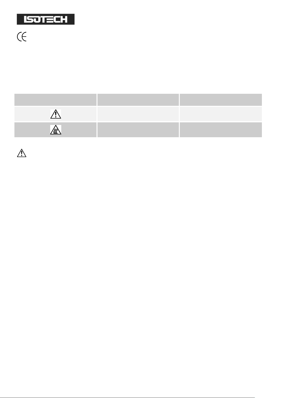
Symbol Identification
Publication
Description
ISO3864
Caution (refer to manual)
IEC 417
Caution, Hot Surface
EMC INFORMATION
This product meets the requirements of the European Directive on Electromagnetic Compatibility (EMC)
89/336/EEC as amended by EC Directive 92/31/EEC and the European Low Voltage Directive 73/25/EEC, amended
by 93/68/EEC. To ensure emission compliance please ensure that any serial communications connecting leads are
fully screened.
The product meets the susceptibility requirements of EN 50082-1, criterion B.
ELECTRICAL SAFETY
This equipment must be correctly earthed.
This equipment is a Class 1 Appliance. A protective earth is used to ensure the conductive parts cannot become live
in the event of a failure of the insulation.
The protective conductor of the flexible mains cable which is coloured green/yellow MUST be connected to a suitable
earth.
The blue conductor should be connected to Neutral and the Brown conductor to Live (Line).
Warning: Internal mains voltage hazard. Do not remove the panels.
There are no user serviceable parts inside. Contact your nearest Isotech agent for repair.
Voltage transients on the supply must not exceed 2.5kV.
Conductive pollution, e.g. Carbon dust, must be excluded from the apparatus. EN61010 pollution degree 2.
The apparatus has two input connectors for temperature sensors, see Figure 1. These inputs are only suitable for
either a thermocouple or resistance thermometer. No other sensor or signal may be connected.
Environmental Ratings
Operating Temperature 5-35°C
Relative Humidity 5-95%, non condensing
Page 4 of 24
Saturn/Cyclops 878 Iss.05 – 08/18
Page 5

HEALTH AND SAFETY INSTRUCTIONS
1. Read this entire manual before use.
2. Wear appropriate protective clothing.
3. Operators of this equipment should be adequately trained in the handling of hot and cold items and liquids.
4. Do not use the apparatus for jobs other than those for which it was designed, i.e. the calibration of
thermometers.
5. Do not handle the apparatus when it is hot (or cold), unless wearing the appropriate protective clothing and
having the necessary training.
6. Do not drill, modify or otherwise change the shape of the apparatus.
7. Do not dismantle the apparatus without disconnecting it from the supply and leaving time for it to reach
ambient temperatures.
8. Do not use the apparatus outside its recommended temperature range
9. If cased, do not return the apparatus to its carrying case until the unit has cooled.
10. There are no user serviceable parts inside. Contact your nearest Isotech agent for repair.
11. Ensure materials, especially flammable materials are kept away from hot parts of the apparatus, to prevent
fire risk.
Page 5 of 24
Saturn/Cyclops 878 Iss.05 – 08/18
Page 6

CAUTIONARY NOTE
ISOTECH PRODUCTS ARE INTENDED FOR USE BY TECHNICALLY TRAINED AND COMPETENT
PERSONNEL FAMILIAR WITH GOOD MEASUREMENT PRACTICES.
IT IS EXPECTED THAT PERSONNEL USING THIS EQUIPMENT WILL BE COMPETENT WITH THE
MANAGEMENT OF APPARATUS WHICH MAY BE POWERED OR UNDER EXTREMES OF TEMPERATURE, AND
ARE ABLE TO APPRECIATE THE HAZARDS WHICH MAY BE ASSOCIATED WITH, AND THE PRECAUTIONS
TO BE TAKEN WITH, SUCH EQUIPMENT.
Page 6 of 24
Saturn/Cyclops 878 Iss.05 – 08/18
Page 7

INTRODUCTION
This patented furnace has been uniquely designed.
Introduced by Isothermal Technology in 1984, the full potential of the bath has yet to be realised.
The lower temperature limit is dictated by the controller and the furnace time constant so that by reducing the heater
power (HL) to about 5 to 10% of full power good results can be obtained even at temperatures just above room
temperature.
Page 7 of 24
Saturn/Cyclops 878 Iss.05 – 08/18
Page 8

THEORY OF OPERATION
The windings that heat the Cyclops are specially profiled to give a uniform area of constant temperature in the central
part of the oven or furnace.
The theory behind the Isotech Spherical Black Body Source is that a solid conducting sphere suspended in the centre
of a hollow outer, heated sphere will take up the temperature of the outer hollow heated sphere by convection and
radiation to give a very stable temperature reference, without end, or edge effects.
Page 8 of 24
Saturn/Cyclops 878 Iss.05 – 08/18
Page 9

SPHERICAL BLACK BODY SOURCE
FEATURES
1. It is spherical and its design ensures a central zone of constant temperature.
2. The temperature of the furnace is controlled from a microprocessor based controller which can incorporate
remote facilities, enabling the furnace temperatures to be pre-programmed from a computer. Thus, totally
automatic readings become possible and easily realisable.
3. Normally the windings will require replacing after 2 or 4 years of operating (dependant on work cycle) and so
the furnace has been designed with ease of maintenance in mind. A spare set of windings is provided free
with each furnace, as is a comprehensive manual.
Page 9 of 24
Saturn/Cyclops 878 Iss.05 – 08/18
Page 10

Figure 1: Saturn/Cyclops Assembly Detail
Page 10 of 24
Saturn/Cyclops 878 Iss.05 – 08/18
Page 11

PRINCIPLE OF OPERATION
The Spherical Black Body Source comprises of a number of concentric shells. (See Figure 1) The outer layer of the
spun metal is for containment and support, inside this is a layer of ceramic fibre. Within the fibre is a ceramic
spherical mantle containing the heater windings.
Lastly in the centre of the furnace is the Cyclops Black Body Source.
Page 11 of 24
Saturn/Cyclops 878 Iss.05 – 08/18
Page 12

Size:
425mm diameter sphere
Weight:
25 Kilos
Temperature Range:
100°C to 1300°C
Warm-up times*
1 hour to 700°C
3 hours to 1300°C
Power Supply:
3KW Typically
Single Phase
Ambient Operating Temperature:
0 to 50°C
<70% RH
SPECIFICATIONS
*
These times may increase as the windings age or if the supply voltage is low.
Each Unit Comprises Of:
1. Spherical Black Body Source
2. Cyclops
3. Controller
4. Spare set of windings
5. Thermocouple
6. Manual/Guarantee
7. Unpacking Instructions
Page 12 of 24
Saturn/Cyclops 878 Iss.05 – 08/18
Page 13

PRECAUTIONS
Some precautions should be noted as follows:
1. Although the furnace has been insulated with the best available ceramic fibre material, some heat does
escape, in fact it is essential for the correct operation of the furnace that it should.
This means that, at high temperatures the outside surface of the furnace becomes hot. If this is a safety
problem then a protecting grill should be built round the furnace.
2. Over Temperature: All the materials used in the construction of the furnace have been rated to 1,400°C.
However, at these temperatures the life expectancy of the heater windings for example are very short. We
therefore recommend an upper temperature of 1300°C for the bath.
3. The furnace must be mounted on a suitable solid flat surface, horizontal to within ±5°.
Page 13 of 24
Saturn/Cyclops 878 Iss.05 – 08/18
Page 14

ON ARRIVAL
On unpacking the Spherical Black Body Source you will find 4 parts:
1. The controller.
2. The Furnace itself.
3. The Spherical Black Body Source and a pack of Kaowool.
4. A packet containing the control thermocouple, a spare set of windings and this instruction book, (sometimes
the windings will be stored inside the furnace).
To assemble the furnace, use the following procedure:
a. Carefully remove all the packing material.
b. Stand the furnace on a flat surface and carefully unscrew the upper half of the outer Sphere.
c. Lift off the upper half of the sphere and the ceramic fibre insulation.
d. You will then see the inner sphere containing the heater windings.
e. The Cyclops fits inside the inner sphere with a layer of Kaowool around it, see Figure 1. It is recommended
that two people continue with the procedure.
Carefully lift the upper hemisphere taking care not to stress the two heater lead wires. When the top half
ceramic is clear, position the insulation and the target to allow access for the target hole through the furnace
aperture.
Ensure the control thermocouple and ceramic tube are located as Figure 2. Should the height need adjusting
use the adjustment screw on the base of the unit.
f. Reassemble the furnace.
g. Unpack the controller and connect the cable marked "heater" to the cable from the lower half of the furnace.
h. Connect a plug to the cable from the controller marked "supply". Note - the controller will normally require
a 13 amp supply at 220/240V.
i. Put the control thermocouple inside the winding shell as shown in diagram below.
Page 14 of 24
Saturn/Cyclops 878 Iss.05 – 08/18
Page 15

CAUTION
Before switching on, check that there is approximately 20Ω between the furnace heater windings and greater than 5
Megohms between windings and outer furnace case.
Assuming this is so you may now commission the furnace.
Please read the controller instruction manual carefully before proceeding.
Figure 2: Cyclops Assembly Diagram Exploded View (shown in section)
Page 15 of 24
Saturn/Cyclops 878 Iss.05 – 08/18
Page 16

USING THE CONTROLLER
FRONT PANEL LAYOUT
The Temperature Controller
The controller has a dual display, the upper display indicates the nominal block temperature, and the lower display
indicates the desired temperature or setpoint.
Altering the Setpoint
To change the setpoint of the controller simply use the UP and DOWN keys to raise and lower the setpoint to the
required value. The lower display changes to indicate the new setpoint.
Advanced Controller Features
Setpoint Ramp Rate
By default the bath is configured to heat (and cool) as quickly as possible. There may be some calibration applications
where it is advantageous to limit the heating (or cooling rate).
An example might be when testing bimetallic thermostats, by forcing the bath to heat at a controlled rate it is easier
to determine the temperature at which the thermostat changes state.
The bath can have its heating rate limited with the Setpoint Ramp Rate feature. This feature is accessed from the
Scroll key. Depress the key until the display shows,
SPrr
Page 16 of 24
Saturn/Cyclops 878 Iss.05 – 08/18
Page 17

On the Upper Display, the lower display will show the current value from OFF (default) to 999.9. The desired rate is
set here with the UP and DOWN keys, the units are °C/min.
When the SPrr is active the controller display will show "RUN", the lower setpoint display will now automatically
update with the current value, known as the working setpoint. The setpoint can be seen by pressing either the UP
and DOWN key.
The Setpoint ramp rate operates when the bath is heating and cooling.
Instrument Address
The controller has a configurable "address" which is used for PC communications. Each instrument has an address,
this allows several instruments to be connected in parallel on the same communications bus. The default value is 1.
This address would only need to be changed if more than one bath is connected to the same PC port.
To check the Address value press the scroll key until the top display indicates,
Addr
The lower display will show the current value that can be modified with the UP and DOWN keys.
Monitoring the Controller Status
A row of beacons indicate the controllers status as follows,
OP1 Heat Output
REM This beacon indicates activity on the PC interface
Units
Momentary pressing the Scroll key will show the controller units °C or °F.
Diagnostic alarms
These indicate that a fault exists in either the controller or the sensor.
Page 17 of 24
Saturn/Cyclops 878 Iss.05 – 08/18
Page 18

Display
shows
What it means
What to do about it
EE.Er
Electrically Erasable Memory Error:
The value of an operator or configuration parameter has been
corrupted
Contact Isotech
S.br
Sensor Break:
Input sensor is unreliable or the input
signal is out of range.
Contact Isotech
HW.Er
Hardware error
:
Indication that a module is of the wrong
type, missing or faulty
Contact Isotech
LLLL
Out of Display range, low reading
Contact Isotech
HHHH
Out of Display range, high reading
Contact Isotech
Err1
Error 1: ROM self-test fail
Consult Isotech
Err2
Error 2: RAM self-test fail
Consult Isotech
Err3
Error 3: Watchdog fail
Consult Isotech
Err4
Error 4: Keyboard failure
Stuck button, or a button was pressed during power up.
Switch the power off and then
on without touching any of the
controller buttons.
Err5
Error 5: Input circuit failure
Consult Isotech
Pwr.F
Power failure
. The line voltage is too low
Check that the supply to the
controller is within the rated
limits
CONTROLLER ERROR MESSAGES
The instruments include powerful diagnostics and in the unlikely event of an internal failure, or a sensor error, one of
the following error messages may be displayed.
Page 18 of 24
Saturn/Cyclops 878 Iss.05 – 08/18
Page 19

COMMISSIONING
During its trip to you, the package containing the furnace may have become damp; therefore, we recommend the
following initial procedure:
1. Switch on the furnace/controller and set the temperature to 100°C. Allow the temperature to reach 100°C
and stabilise there for 2 hours.
2. Increase the set temperature to 200°C. Allow 2 hours for stabilisation.
3. Increase the temperature in 100°C steps allowing 1 to 2 hours between each change until the furnace has
reached 1,000°C.
Your Spherical Black Body Source is now ready for use!
SAMPLE RESULTS
Page 19 of 24
Saturn/Cyclops 878 Iss.05 – 08/18
Page 20

USING THE PC INTERFACE
The bath includes an RS422 PC interface and a special converter cable that allows use with the a standard RS232 port.
When using the bath with an RS232 port it is essential that this converter cable is used. Replacement cables are
available from Isotech, part number ISO-232-432. A further lead is available as an option, Part Number ISO-422-422
lead which permits up to 5 instruments to be daisy chained together.
The benefit of this approach is that a number of calibration baths may be connected together in a "daisy chain"
configuration - and then linked to a single RS232, see diagram.
Note: The RS 422 standard specifies a maximum lead length of 1200M (4000ft). A true RS422 port will be required to
realise such lead lengths. The Isotech conversion leads are suitable for maximum combined lead lengths of 10M that is
adequate for most applications.
CONNECTIONS
For RS232 use simply connect the Isotech cable, a 9 to 25 pin converter is included to suit PCs with a 25 pin serial
converter.
RS422 Connections
Pin Connection
4 Tx+ A
5 Tx- B
8 Rx+ A
9 Rx- B
1 Common
Page 20 of 24
Saturn/Cyclops 878 Iss.05 – 08/18
Page 21

CAL NOTEPAD
Cal Notepad can be used can be used to log and display values from the Dry Blocks and an optional temperature
indicator such as the milliK or TTI-10. The software requires Windows 9X, XP, a minimum of 5Mb of free hard drive
space and free serial ports for the instruments to be connected.
DEVELOPMENT
Cal NotePad was developed by Isothermal Technology using LabVIEW from National Instruments. The license details
are shown on the download page and in the Cal Notepad manual.
Page 21 of 24
Saturn/Cyclops 878 Iss.05 – 08/18
Page 22

HOW TO INSTALL CAL NOTEPAD
1. Download the ZIP from http://www.isotech.co.uk/downloads (7.6Mb)
2. Extract the files to a temporary folder
3. Run setup.exe
4. Follow the prompts which will install the application, a user manual with setup information and the necessary
LabVIEW run time support files.
5. Should you ever need to uninstall the software then use the Add/Remove Programs option from the Control
Panel.
PROTOCOL
The instruments use the "Modbus Protocol"
If required, e.g. for writing custom software the technical details are available from our Document Library at
http://www.isotech.co.uk
Page 22 of 24
Saturn/Cyclops 878 Iss.05 – 08/18
Page 23

GETTING THE BEST FROM YOUR SATURN
INTRODUCTION
Although every effort is made to get complete symmetry inside the Saturn. Variations in tube wall thickness, winding
spacing, ceramic densities inevitably mean that there is a small consistent and reproducible profile round the inner
equalizing sphere.
After assembly, the following test procedure will allow an evaluation of this profile. The profile will be consistent
throughout the life of the furnace and enable calibration to be performed to an accuracy of ¼°C.
1. Set temperatures to 100°C and allow 1 to 1½ hours for stabilisation to occur.
2. Make two thermocouples type R or S, (or use two model 1600's available from ISOTECH).
3. Place 1 in a designated pocket, place the second thermocouple in each of the other pockets in turn, taking
readings in each pocket compared to the standard pocket.
4. Repeat survey at 200°C intervals.
5. Use the survey to provide a correction factor to the results subsequently obtained.
Page 23 of 24
Saturn/Cyclops 878 Iss.05 – 08/18
Page 24

PART NO:
DESCRIPTION:
877-01-02
Windings (2)
932-20-16
Kaowool
935-10-24
Cable Gland/Con Block
935-35-58/59B
Plug/Socket
935-21-21
Relay 240V
935-12-20
Relay 110V
935-12-04
Fuse
935-11-05
Fuse Holder
935-27-01
Neon/Switch
935-06-102B
Controller - 2208L Eurotherm
935-14-21
Control Thermocouple
878
Black Body Cyclops
SPARE PARTS LIST
Page 24 of 24
Saturn/Cyclops 878 Iss.05 – 08/18
 Loading...