

Page 1

User Maintenance Manual
PEGASUS ADVANCED 4853
Telephone: +44 (0)1704 543830 Fax: +44 (0)1704 544799 Email: info@isotech.co.uk Website: www.isotech.co.uk
Isothermal Technology Limited, Pine Grove, Southport, Merseyside, PR9 9AG, England
Pegasus (Advanced) 01-10/14
Page 2

Guarantee
ⓒIsothermal Technology Limited
This instrument has been manufactured to exacting standards and is guaranteed for twelve
months against electrical break-down or mechanical failure caused through defective material or
workmanship, provided the failure is not the result of misuse.
In the event of failure covered by this guarantee, the instrument must be returned, carriage paid,
to the supplier for examination and will be replaced or repaired at our option.
FRAGILE CERAMIC AND/OR GLASS PARTS ARE NOT COVERED BY THIS GUARANTEE
INTERFERENCE WITH OR FAILURE TO PROPERLY MAINTAIN THIS INSTRUMENT MAY
INVALIDATE THIS GUARANTEE
The company is always willing to give technical advice and assistance where appropriate. Equally,
because of the programme of continual development and improvement we reserve the right to
amend or alter characteristics and design without prior notice. This publication is for information
only.
This handbook contains information that has been reproduced with the kind permission of
Eurotherm. Such data is subject to the following notice.
ⓒ2014 Eurotherm Limited
Eurotherm, the Eurotherm logo, Chessell, nanodac, and Itools, are trademarks of Invensys plc, its
subsidiaries and affiliates.
All rights are strictly reserved. No part of this document may be reproduced, modified or
transmitted in any form by any means, neither may it be stored in a retrieval system other than
for the purpose to act as an aid in operating the equipment to which the document relates, without
the prior written permission of Invensys Eurotherm Limited.
Eurotherm Limited pursues a policy of continuous development and product improvement. The
specifications in this document may therefore be changed without notice. The information in this
document is given in good faith, but is intended for guidance only.
Isothermal Technology Limited
Pine Grove, Southport, Merseyside, PR9 9AG, England
Telephone: +44 (0)1704 543830 / Fax: +44 (0)1704 544799
Email: info@isotech.co.uk / Website: www.isotech.co.uk
2
Page 3

Contents
1 UNPACKING AND INITIAL INSPECTION ................................................................................. 5
2 BEFORE YOU USE THE EQUIPMENT ......................................................................................... 6
3 SUMMARY OF SYMBOLS .......................................................................................................... 7
4 ELECTRICITY SUPPLY .............................................................................................................. 8
5 THE UNIT MUST BE EARTHED .......................................................................................... 9
6 EMC INFORMATION ........................................................................................................ 10
7 CAUTIONARY NOTE ....................................................................................................... 11
8 SAFETY WARNINGS ....................................................................................................... 12
8.1 DO NOT MODIFY OR DISASSEMBLE .................................................................................................. 12
8.2 BEWARE OF ELECTRICAL CONSIDERATIONS ........................................................................................ 12
8.3 BE CAREFUL WHERE IT IS USED ...................................................................................................... 12
8.4 BE CAREFUL WITH EXTREMES OF TEMPERATURE ................................................................................. 12
8.5 BE CAREFUL WITH INSERTS ........................................................................................................... 12
9 CONSIDER THE ENVIRONMENT ............................................................................................ 13
10 INTRODUCTION ................................................................................................................... 14
10.1 COMPARISON CALIBRATION .......................................................................................................... 14
10.2 BASIC OPERATION ...................................................................................................................... 14
10.3 SITE OR SELF-CONTAINED CALIBRATORS ......................................................................................... 14
10.4 EXTERNAL STANDARDS + BASIC .................................................................................................... 15
10.5 ADVANCED CALIBRATORS .......................................................................................................... 15
11 MODE OF OPERATION ......................................................................................................... 16
11.1 METAL BLOCK BATH ................................................................................................................... 16
11.1.1 Assembling the Insert ................................................................................................ 16
11.2 BLACKBODY SOURCE ................................................................................................................... 17
11.2.1 Assembling the Insert ................................................................................................ 17
11.3 FAST COOL DOWN PROBE (OPTION) ....................................................................................... 18
12 OPERATION OF THE ADVANCED DRY BLOCK TEMPERATURE CALIBRATOR ....................... 19
12.1 A TOUR OF THE EQUIPMENT ........................................................................................................ 19
12.2 THE USER INTERFACE START UP SCREEN AND CONTROLS ................................................................ 20
12.3 THE ISOTECH HOMEPAGE .......................................................................................................... 20
12.4 THE THERMOSTAT TESTING PAGE ............................................................................................ 20
12.5 THE PROGRAM PAGE (NO ACTIVE PROGRAM) ................................................................................. 21
12.6 THE PROGRAM PAGE (ACTIVE PROGRAM RUNNING) ......................................................................... 21
12.7 THE USER ACCESS PAGE ........................................................................................................... 21
13 GETTING STARTED .............................................................................................................. 22
13.1 CHANGING THE SET POINT ........................................................................................................... 22
14 USING THE ADVANCED FEATURES OF THIS EQUIPMENT ................................................... 23
14.1 TO SET FROM THE FRONT PANEL ................................................................................................... 23
14.1.1 Operator Access .............................................................................................................. 23
14.1.2 Supervisor Access (in addition to the above functions) ....................................................... 23
14.1.3 Engineer Access .............................................................................................................. 23
14.2 HOW TO LOG IN AS THE SUPERVISOR ......................................................................................... 24
3
Page 4

14.3 HOW TO LOG IN AS THE ENGINEER ............................................................................................. 24
14.4 HOW TO CHANGE INPUT SENSOR ON CHANNELS 1, 2 AND 3 ................................................................ 25
14.5 THERMOSTAT TESTING USING THE ADVANCED UNIT .......................................................................... 26
14.6 ENABLING THE AUTOTUNE FEATURE ............................................................................................ 27
14.7 USING THE SETPOINT TRIM FEATURE .......................................................................................... 27
14.8 HOW TO CHANGE THE DATE AND TIME OR THE LANGUAGE OF THE ADVANCED EQUIPMENT .......................... 28
14.9 THERMOMETER INPUT CHANNELS ................................................................................................... 28
14.10 PROCESS TO APPLY A USER CALIBRATION TO THE CONTROLLER USING A PRT CONNECTED TO CHANNEL 1 ....... 29
14.11 THE NETWORK INTERFACE .................................................................................................... 30
14.12 TO ACCESS THE NETWORK INTERFACE ..................................................................................... 30
14.13 THE WEB BROWSER .............................................................................................................. 30
14.13.1 Supported Browsers: ...................................................................................................... 31
14.13.2 The clickable links will allow you to: ................................................................................ 31
14.14 DATA LOGGING ........................................................................................................................ 31
14.15 FTP SERVER ARCHIVING ............................................................................................................ 32
14.16 PROGRAMMER FUNCTION ........................................................................................................... 32
14.17 PROGRAM DETAILS ................................................................................................................... 33
14.17.1 Operation ...................................................................................................................... 33
14.17.2 Status ........................................................................................................................... 33
14.17.3 Program ........................................................................................................................ 33
14.17.4 Holdback Style ............................................................................................................... 33
14.17.5 Program ........................................................................................................................ 33
14.17.6 Ch1 Holdback ................................................................................................................ 34
14.17.7 Ch1 Holdback value ....................................................................................................... 34
14.17.8 Ch2 Holdback ................................................................................................................ 34
14.17.9 Ch2 Holdback value ....................................................................................................... 34
14.17.10 Ramp Style .................................................................................................................. 34
14.17.11 Time ........................................................................................................................... 34
14.17.12 Ch1 Ramp Units ........................................................................................................... 34
14.17.13 Ch2 Ramp Units ........................................................................................................... 34
14.18 HOW TO CREATE A SIMPLE PROGRAM USING THE CONTROLLER INTERFACE ............................................ 35
14.19 TO ENABLE/RUN THIS PROGRAM ............................................................................................... 36
14.20 TO EDIT AN EXISTING PROGRAM ................................................................................................ 36
14.21 USING THE HOLDBACK FEATURE ................................................................................................ 36
15 CONNECTING TEMPERATURE SENSORS.............................................................................. 38
15.1 PLATINUM RESISTANCE THERMOMETERS, PRTS ................................................................................. 38
15.2 INPUT CONNECTIONS .................................................................................................................. 38
15.3 CONNECTING THERMOCOUPLES ...................................................................................................... 38
15.4 CONNECTING 4 – 20MA CURRENT TRANSMITTERS .............................................................................. 39
15.4.1 Using the Current Loop Interface (935-06-161) ................................................................. 39
16 SPECIFICATION ................................................................................................................... 40
17 CONNECTING TO A PC ......................................................................................................... 41
17.1 ISOTECH CONFIG UTILITY ............................................................................................................ 41
17.2 ISOTECH I-CAL EASY ................................................................................................................. 42
17.3 PROGRAM EDITOR ...................................................................................................................... 42
17.4 REVIEW ................................................................................................................................... 43
18 ACCESSORIES ...................................................................................................................... 44
4
Page 5

1 Unpacking And Initial Inspection
Our Packing Department uses custom designed packaging to send out your unit, but as accidents
can still happen in transit, you are advised, after unpacking the unit, to inspect it for any sign of
shipping damage and confirm that your delivery is in accordance with the packing check list. If
you find any damage or that part of the delivery is missing notify us or our agent and the carrier
immediately. If the unit is damaged you should keep the packing for possible insurance
assessment.
5
Page 6

2 Before You Use The Equipment
Please read the handbook and familiarise yourself with all warnings, hazards and safety
information. Regularly inspect the equipment, accessories and electrical leads. Do not use if there
is any sign of damage. Keep the equipment clean, only use a damp cloth. Do not use solvents or
allows liquids to enter the case.
6
Page 7
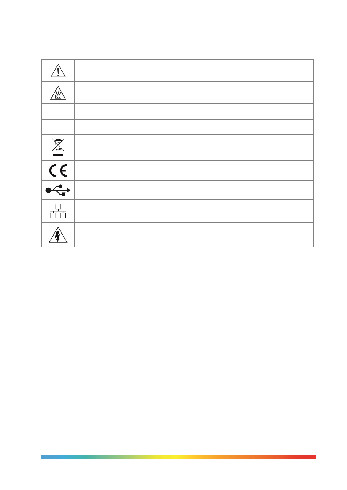
3 Summary of Symbols
ISO3864 – Caution, read the entire manual before use
IEC 417 – Caution, hot surface (risk of burn)
O
Off l On
Waste Electrical and Electronic Equipment (WEEE directive) symbol
Complies with European regulations (CE mark)
USB symbol
Ethernet RJ45 symbol
Risk of Electrical Shock
7
Page 8

4 Electricity Supply
Before connecting to the electricity supply please familiarise yourself with the parts of the manual
relevant to your model.
Your unit's supply voltage requirement is specified on a label on the instrument along with the
serial number. Only connect to a power supply matching the requirement stated on the equipment.
8
Page 9

5 The Unit Must Be Earthed
Colour
Function
Green/yellow
Earth (Ground)
Brown
Live (line)
Blue
Neutral
This equipment is a Class 1 Appliance and must be earthed (grounded). Use the supplied power
cord and plug it directly into an AC outlet with a protective earth.
If using an alternative cord ensure it is of adequate rating.
If fitting a plug to the cable we have supplied the cable is colour coded as follows:
Do not use the equipment if it is not correctly earthed. If in doubt consult Isothermal Technology
Ltd or a qualified electrician.
9
Page 10

6 EMC Information
This product meets the requirements of the European Directive on Electromagnetic Compatibility
(EMC) 89/336/EEC as amended by EC Directive 92/31/EEC and the European Low Voltage
Directive 73/25/EEC, amended by 93/68/EEC. To ensure emission compliance please ensure that
connecting leads are fully screened.
The product meets the susceptibility requirements of EN 50082-1, criterion B.
10
Page 11

7 Cautionary Note
Operators of this equipment should be adequately trained in the handling of hot and cold items.
It is important the user has been trained about the selection and use of liquids over a wide
temperature range. It is expected that personnel using this equipment will be competent with the
management of apparatus which may be powered or under extremes of temperature and are able
to appreciate the hazards which may be associated with and the precautions to be taken with,
such equipment.
11
Page 12

8 Safety Warnings
8.1 Do Not Modify Or Disassemble
Do not use the apparatus for jobs other than those for which it was designed, i.e. the
calibration of thermometers
There are no user serviceable parts inside. Do not dismantle or modify the apparatus. For
repair information contact Isothermal Technology Ltd
For equipment with fans, the fan should kept free from dust build up; a soft brush or
vacuum cleaner may be used on the external grill
8.2 Beware Of Electrical Considerations
The equipment is for installation category II (transient voltages) and pollution degree
II in accordance with IEC 664 at altitudes to 2000 metres
Sensor Input Connection must never exceed 30V with reference to ground
Thermostat test inputs should be voltage free: isolate from any voltage source during test
8.3 Be Careful Where It Is Used
The equipment is not for use in hazardous areas or in an environment close to flammable
materials or gases
The equipment must be used on a flat level surface, with adequate space around it for air
flow and avoid blocking ventilation slots
Ensure free space above the unit to avoid risk of burn or fire
The equipment should only be used indoors
Site in a way that allows access to the power switch, and to allow the cable to be
disconnected
Avoid excessive heat, humidity, dust and vibration ensuring it will not be subjected to
dripping or splashing liquids
8.4 Be Careful With Extremes Of Temperature
In normal use the calibration volume, inserts and probes will become very hot and present
a burn hazard
Do not remove inserts, probes or handle the equipment when it is hot or cold.
Allow the equipment and accessories to reach a temperature between ambient and 70°C
before switching off or storing the equipment in its case
Do not use the equipment outside its recommended temperature range
Operating the equipment at extremes of temperature for extended periods may call for
early replacement of the heating assembly
Wear appropriate protective clothing
8.5 Be Careful With Inserts
Only use inserts supplied with, or ordered specifically for, this model
Do not handle inserts while they are very hot or cold
Inserts for low temperature models may melt and cause a fire if used in high temperature
models
Only use Isotech inserts which are specially treated to avoid them from becoming stuck in
the calibration volume
Do not use powders, liquids or compounds in the insert; this may lead to the insert or
probes becoming stuck
12
Page 13

9 Consider The Environment
The equipment should be recycled or disposed of in a proper way; following the Waste
Electrical and Electronic Equipment (WEEE) directive
13
Page 14

10 Introduction
The purpose of the Pegasus models is to provide an adjustable isothermal enclosure for
calibration purposes. It has been designed to be rugged and easily maintained.
The isothermal enclosure consists of a small furnace into which an insert can be placed. Items
for calibration are placed in suitably drilled holes in the insert. The replaceable inserts enable a
variety of items to be calibrated.
The furnace consists of a specially wound tube assembly. A control sensor is used by the
temperature controller to sense the furnace temperature.
An internal fan runs continuously and cools the electronics in the instrument.
Note: the units’ on/off switch is located on the power inlet. Take care NOT to switch
the unit off when it is hot, allow to cool first.
10.1 Comparison Calibration
By definition, one compares industrial thermometers to a calibrated standard. There are three
methods commonly used.
10.2 Basic Operation
Using the controller as the “calibrated standard”. This method means that the
complete bath is calibrated by comparing the controller reading to a calibrated
standard placed in the bath.
This is a common method but is unsafe since the control sensor is
a) inaccessible
b) in the wrong place to give correct temperature of the insert
For these reasons it fails to satisfy ISO9000 and gives large uncertainties.
The Pegasus should always be used with a calibrated sensor alongside the test devices.
10.3 Site or Self-Contained Calibrators
In these an indicator and external calibrated sensor are used to measure
the temperature of the insert. This arrangement gives good results and
traceability. To recalibrate however it does mean sending the whole
calibrator back to the calibration laboratory. The calibrator is selfcontained, self-sufficient and meets ISO9000 requirements.
14
Page 15

10.4 External Standards + Basic
Here a separate indicator and calibrated sensor
are used to measure the inserts temperature.
With a suitable indicator such as the Isotech
milliK this gives the most accurate and reliable
results, depending on the indicator.
It means that the calibrator does not need
calibrating; only the indicator and its calibrated
sensor need re-calibration. One indicator may
be used with a range of blocks. This method
also meets ISO9000 requirements.
10.5 ADVANCED Calibrators
The ADVANCED model includes an indicator with channels for both
the test thermometers and an external calibrated sensor used to
measure the temperature of the insert. This allows best practice
calibration with established traceability and uncertainty. To
recalibrate however it does mean sending the whole calibrator back
to the calibration laboratory. The calibrator is self-contained for
reference and test probes, self-sufficient and meets ISO9000
requirements.
15
Page 16

11 Mode Of Operation
11.1 Metal Block Bath
The thermometers under test are placed into suitable holes in the metal insert. For
the ADVANCED and S models a calibrated reference probe should be placed into
the insert and the actual temperature can be read from the temperature
indicator. For the Basic models an external temperature indicator should be used.
For traceable calibration the actual value of the insert temperature should be
recorded along with the values from the sensors under test.
11.1.1 Assembling the Insert
The insert is connected to EARTH (Ground) by a metal spike, see diagram. It is
essential this connection is made.
To assemble the insert:
1. Ensure furnace is cool.
2. Slide the long ceramic insulator down the furnace tube so that the tip of the spike
protrudes. (This can be checked by using a ruler or similar).
3. Carefully lower the insert using the extractor tool.
4. Unscrew extractor tool.
5. Finally add the smaller top ceramic insulator.
Note: insulators must be used as shown
1. Top Ceramic Insulation
2. Furnace
3. Insert
4. Lower Ceramic Insulation
5. Earth Spike
6. Side View of Pegasus
16
Page 17

11.2 Blackbody Source
The Blackbody Target Kit can be added for simple calibration on infrared thermometers.
Place the target into the well with the supplied thermocouple fitted. For the ADVANCED and S
models the actual temperature from the thermocouple can be read from the temperature
indicator. For the Basic models an external temperature indicator should be used. The test IR
thermometers should be compared to this value.
11.2.1 Assembling the Insert
Where the unit is to be used with a standard or special insert, the insert ceramics must be
assembled as per the drawing below.
1. Ensure furnace is cool.
2. Slide the long ceramic insulator (970-01-03C) down the furnace tube so that it rests on the
base.
3. Carefully lower the smaller ceramic (970-01-03B) inside the furnace to rest on the lower
ceramic.
4. Load the blackbody (970-01-02) with the reference thermocouple installed (970-20-01).
5. Finally add the upper top ceramic insulator (970-01-03A).
1. Reference Sensor 970-20-01
2. Ceramic Insulation 970-01-03A
3. Pegasus Furnace 853-07-00
4. Blackbody Target 970-01-02
5. Ceramic Insulation 970-01-03B
6. Ceramic Insulation 970-01-03C
7. 970 Pegasus case
17
Page 18

11.3 FAST COOL DOWN PROBE (OPTION)
The fast cool down probe can be attached to a suitable air supply and then placed into the Pegasus
insert for rapid cooling.
Take care when placing the probe into the hot block.
Ensure the air supply is set to give an appropriate flow rate. Guard against setting so high that
the probe may be blown from the insert.
1. Rapid Cool Probe
2. Upper Ceramic
3. Insert
4. Lower Ceramic
5. Earth Spike
6. Airflow (maximum 10 litres per
minute)
18
Page 19

12 Operation Of The ADVANCED Dry Block Temperature Calibrator
12.1 A Tour Of The Equipment
Figure 1: Main Input and Output for the ADVANCED equipment
1. Main supply voltage connection socket
This socket allow the Mains Voltage to be
applied to power up the equipment. Use only
the supplied lead or a suitably specified IEC
alternative. Confirm the supply voltage using
the ratings label on the rear of the
equipment.
2. Power On/Off switch
Once the Power lead is connected, this switch
will power up and down the equipment
3. Fuse carrier and window showing fuse
rating
With the mains cable disconnected, the fuse
carrier can be removed for the inspection or
replacement of the fuse. The fuse rating is
displayed through the window.
4. Channels 1 and 2 PRT input sockets
These allow for the connection of external
Platinum resistance thermometers. Warning
– Do not connect any other form of input to
these sockets.
5. Channels 1,2 and 3 Thermocouple input sockets
These allow for the connection of a range of Thermocouples to be connected. Warning – Do
not connect any other form of input to these sockets.
6. USB socket
This allows for the connection of a USB memory stick or the connection of a USB keyboard.
Please see relevant note at the end of this section.
7. Full colour graphical user interface display
¼ VGA crystal clear, IP66 wash-down display
8. Thermostatic testing input sockets channels 1 and 2
Allows for two thermostats to be connected simultaneously to verify opening or closing
temperatures.
9. Ethernet (RJ45) socket
This allows for the connection of the equipment to either a PC for direct connection or to a
network to allow network access.
Please note at the end of this section
19
Page 20

Note: Precautions against electrostatic discharge should be taken when the
instrument terminals are being accessed. The USB and Ethernet connections are
particularly vulnerable.
When using a USB extension cable, a high quality screened cable must be used. The
total length of USB cable between the device and the USB port must not exceed 3
metres (10 ft.)
12.2 The USER INTERFACE Start Up
Screen And Controls
Figure 2
1. ISOTECH splashscreen
2. PAGE button
3. SCROLL button
4. DOWN button
5. UP button
12.3 The ISOTECH Homepage
Figure 3
1. Channel 1 display value
2. Channel 2 display value
3. RECORD icon
4. Product identifier
5. Block temperature (Process Variable)
6. Set temperature (Working Set Point)
7. Channel 3 display value
8. Setpoint adjust
12.4 The THERMOSTAT TESTING
Page
Figure 4
1. THERMOSTAT 1 freeze temperature
2. THERMOSTAT 1 freeze temperature
3. SENSE value 1 (Normally Open/Closed)
4. SENSE value 2 (Normally Open/Closed)
5. REFERENCE channel temperature display
20
Page 21

12.5 The PROGRAM Page (No Active Program)
Figure 5
1. Current program NAME/STATUS
2. MODE display
3. Program Edit beacon
4. Block temperature (Process Variable)
5. Program Setpoint
6. Program STATUS
12.6 The PROGRAM Page (Active Program Running)
Figure 6
1. Program status (running)
2. Segment type
3. Program progress
4. Segment time remaining
5. Program time remaining
6. Segment progress
12.7 The USER ACCESS Page
Figure 7
1. Channel 1 input type – read only
2. Channel 2 input type – read only
3. Channel 3 input type – read only
4. Channel 1 minus Channel 2 – read only
5. Channel 1 minus Channel 3 – read only
6. IP Type (fixed or dynamic) – read only
7. Setpoint Trim enable/disable – writeable
8. Autotune - writeable
21
Page 22

13 Getting Started
To operate this equipment, place on a suitable surface and visually inspect for any damage, since
either last use, or from transit. Assuming all is well, place the supplied insert or liquid container
in the well at the rear of the equipment.
Using the supplied mains lead, insert into the Main supply voltage connection socket (figure
1, item 1). Ensure the voltage supply and rating of the equipment comply and plug the lead into
the supply.
Press the Power On/Off switch (figure 1, item 2) to power up the equipment. The display will
now illuminate and display the ISOTECH splashscreen (figure 2). The white progress bar at the
bottom of the screen will scroll across the screen showing progress. Normally in the region of 45
seconds.
When the screen has booted up, the home page will be as
figure 3. The equipment will now heat or cool to the last set
point indicated as figure 3, item 7.
To assist in getting started there are some tutorial videos
online at http://www.isotech.co.uk/advanced
13.1 Changing The Set Point
To change the setpoint of the equipment on the ADVANCED
unit:
1. From the ISOTECH homepage, press the SCROLL button once, this will highlight the
SETPOINT ADJUST box.
2. Press the SCROLL button once more and this will allow adjustment of the setpoint via the
UP/DOWN buttons.
3. Scroll to the desired set point as described above.
4. When the temperature is set, press the SCROLL button again to enter and save the setting.
5. The equipment will now raise or lower the block temperature as required.
22
Page 23

14 Using The ADVANCED Features Of This Equipment
The User interface allows for the alteration of certain aspects of the control and indication system.
Examples would be the ability to change the sensor type on any of the Input channels or to change
the resolution of the Channel temperature. This configuration can be set from a PC using the
Isotech Config Utility – see “Connecting to a PC" or from the front panel.
14.1 To Set From The Front Panel
To do this, the user will need to log in to different levels of access using the controller menu
system.
There are three levels of access:
1. Operator Access
2. Supervisor Access
3. Engineer Access
Typical levels of adjustment are outlined below for each level.
14.1.1 Operator Access
Scroll the home pages to allow readable access to controller function
Change the set point of the bath
Change the Sense status of the Freeze display
Enable the Autotune
Enable the set point trim function
14.1.2 Supervisor Access (in addition to the above functions)
Program selection for the program function
Thermometer calibration data entry for Channels 1, 2 and 3
14.1.3 Engineer Access
Change sensor type for channels 1, 2 and 3
Change resolution for channels 1, 2 and 3
Change language selection
Change °C to °F or K
23
Page 24

14.2 How To Log In As The SUPERVISOR
Figure 8
Figure 9
Figure 10
Figure 11
1. Press the Page button to display the Home menu (figure 8)
2. Scroll to LOG IN
3. Press the SCROLL button
4. Press up to scroll to SUPERVISOR in dialogue box
5. Press the SCROLL button to prompt for a passcode
6. Select code 15 from the soft keyboard
7. Press PAGE button to prompt to accept the changes
8. Select Yes and enter with SCROLL button to display the SUPERVISOR screen (figure 9)
9. When logged in as the SUPERVISOR the equipment will control in the normal way
14.3 How To Log In As The ENGINEER
1. Press the Page button to display the Home menu (figure 10)
2. Scroll to LOG IN
3. Press the SCROLL button
4. Press up to scroll to ENGINEER in dialogue box
5. Press the SCROLL button to prompt for a passcode
6. Select code 17 from the soft keyboard
7. Press PAGE button to prompt to accept the changes
8. Select Yes and enter with SCROLL button to display the ENGINEER screen (figure 11)
9. When logged in as the ENGINEER, the equipment will not control the temperature of the
heat source
24
Page 25

14.4 How To Change Input Sensor On Channels 1, 2 And 3
Input sensors can be user defined using the menu system to change to PT100, a range of
thermocouple types, Ohms or Voltage. To change sensor type follow the procedure below:
1. Log in as the ENGINEER
2. Scroll to CHANNEL
3. Select the desired channel for alteration
4. Press the SCROLL button to enter
5. Scroll to MAIN
6. The MAIN Sub Menu will now be displayed
To configure for a PT100:
1. Scroll to TYPE and press SCROLL to enter
2. Press UP to scroll to RTD, press the SCROLL button to enter
3. Scroll to RESOLUTION and press SCROLL to enter
4. Press up to select the Resolution required, press SCROLL to enter
5. Scroll to LIN TYPE and press SCROLL to enter
6. Select PT100 from the list and press SCROLL to enter
7. Ensure RANGE HIGH is set to 800
8. Press the PAGE button until the ENGINEER screen is displayed, scroll to LOG OUT and
enter with the SCROLL button
To configure for a Thermocouple:
1. Scroll to TYPE and press SCROLL to enter
2. Press UP to scroll to THERMOCOUPLE, press the SCROLL button to enter
3. Scroll to RESOLUTION and press SCROLL to enter
4. Press up to select the Resolution required, press SCROLL to enter
5. Scroll to LIN TYPE and press SCROLL to enter
6. Select required thermocouple type from the list and press SCROLL to enter
7. Ensure RANGE HIGH is set to 1200
8. Press the PAGE button until the ENGINEER screen is displayed, scroll to LOG OUT and
enter with the SCROLL button
Important Note: The COLD JUNCTION on Channels 1, 2 and 3 should ALWAYS be set
to CJTypeRemCh3. This value should not ever be changed. Doing so will disable the
cold junction compensation for Channels 1, 2 and 3.
Channel 3 input type should ALWAYS be set to TC+RTD, the thermocouple type can
selected from lower done in the menu.
25
Page 26

How to change from °C to °F or Kelvin:
1. Log in as the Engineer above
2. Select the Channel required for adjustment
3. Select Main from the channel options
4. Scroll down to RANGE UNITS
5. Enter using SCROLL button and select required units
6. Enter value using SCROLL button
7. Press the PAGE button until the ENGINEER screen is displayed, scroll to LOG OUT and
enter with the SCROLL button
Note: Channel 4 is reserved for the control sensor and as such is disabled from user
access.
14.5 Thermostat testing using the ADVANCED unit
The ADVANCED equipment has the facility to test thermostats or thermal switches using the page
featured in figure 4. Up to two thermostats can be tested at the same time.
The system uses Channel 1 as a reference channel to record the temperature of the thermostat
opening or closing. To use this feature, there must be a thermometer connected to Channel 1.
The sense of the thermostat can be changed by the user and each thermostat is referred to as
“FREEZE 1” and “FREEZE 2”. The options are Normally open (N/O) or Normally closed (N/C).
The thermostat is connected via the 2mm input sockets on the controller plate (item 9, figure 1).
You are not required to log in to access this feature.
How to change the SENSE value on the FREEZE display:
1. Scroll to the FREEZE display page
2. Highlight SENSE 1 by pressing the SCROLL button
3. Press the SCROLL button again to access the value and adjust using the up/down buttons
4. Enter the value by pressing the SCROLL button again
5. To adjust SENSE 2, scroll the it at point 2 and adjust as above
Note: if there is no sensor connected to Channel 1 the FREEZE display will return an
“ERROR” message.
26
Page 27

14.6 Enabling The AUTOTUNE Feature
Note: This feature is available on all ADVANCED equipment except PEGASUS.
The ADVANCED equipment has the ability to AUTOTUNE the control parameters to hone the
temperature stability at a specific block temperature. When enabled it will allow the controller to
cycle the temperature of the block and calculate the best values for this temperature. After two
cycles it will install the calculated values and use these for the control loop.
You are not required to log in to access this feature.
To enable the AUTOTUNE feature:
1. Scroll to the USER ACCESS page
2. Press the Scroll button and then select the AUTOTUNE feature using the down button
3. Press the Scroll button again to highlight the feature
4. Use the up/down button to select ON
5. Press the Scroll button again to enter the value.
6. The controller will now begin the tuning process
During the tuning process, AT can now be seen to the left of the clock on the ISOTECH homepage
(figure 3).
To disable the tuning feature during a tune, repeat the process above and select OFF. This will
now disable the tune and install the previous values.
14.7 Using the SETPOINT TRIM feature
This ADVANCED equipment has the facility to adjust the heat source temperature to a value
determined by Channel1 temperature sensor (only Channel 1 will function with this feature).
This allows the user to more accurately bring the block temperature closer to the reference
temperature without making any manual adjustments. This value will automatically adjust every
30 minutes and will not adjust to any value outside of ±5°C of the control sensor value. This will
prevent overheating in the event of a sensor failure of the sensor being accidently removed from
the heat source. In this event the equipment will disable the feature and control in normal mode.
You are not required to log in to access this feature.
To enable the SETPOINT TRIM feature:
1. Ensure a reference sensor is connected to channel 1 and fully immersed into the heat
source
2. Scroll to the USER ACCESS page and scroll down to the SETPOINT TRIM box
3. Press the Scroll button to highlight the feature
4. Press the up/down button to change the value to INPUT 2
5. Enter this with the Scroll button
6. Exit by pressing the PAGE button and scroll to the homepage
The display may change by the difference between the reference temperature and the control
sensor value. This is normal and should not be adjusted.
To exit SETPOINT TRIM mode repeat the process above and enter INPUT 1 and the controller will
now function in normal mode.
27
Page 28

14.8 How to change the Date and Time or the Language of the
ADVANCED equipment
The Date and time of the ADVANCED equipment can be changed to suit local time. This can also
incorporate the any daylight saving time in the time zone of your country or region. The display
language of some of the display screens can also be change to suit the local language.
The options for this are:
English
French
German
Italian
Spanish
Note: Only the Supervisor and Engineer menus will read in the alternative language. The Isotech
Home screen will still read in English when this feature is used.
To change the DATE and TIME or LANGUAGE:
To access these features you will need to log in as the Engineer.
When logged in, scroll to the INSTRUMENT tab on the Engineer homepage
Press the SCROLL button to enter
Scroll to CLOCK and enter by pressing SCROLL button
Alternatively scroll to LOCALE and enter by pressing SCROLL button
Adjust as necessary and exit engineer mode
14.9 Thermometer Input Channels
The ADVANCED equipment has three temperature sensor input channels that can be used for
either a Platinum Resistance Thermometer or a Thermocouple. Channels 1 and 2 can accept
either of these sensors or Channel 3 can accept a Thermocouple.
The thermocouple input connectors used on all three channels have internal cold junction
compensation. This means that the thermocouple can plug directly into the Copper connector
and the controller will automatically compensate for the cold junction of the thermocouple. Ensure
the thermocouple has no additional cold junction as this will introduce errors.
Each of these channels can accept up to eight correction points to improve the linearity of the
thermometer accuracy to the Controller display. These are user defined and are unique to only
one thermometer.
When using the calibration feature, the points must be used in ascending order, that is to say, the
lowest point (Point 1) must be used at the lowest temperature. Each point for the calibration is
based on two values: the temperature at which the value is applied (the point) and the value to
adjust the temperature by (the offset). The factory default setting for each unused channel is
Point -200 and Offset 0.00. This means that if the calibration is enabled then the controller will
ignore these values until they are populated with real values.
The feature functions in the same way irrespective of sensor type.
The calibration (CAL STATUS) has several settings listed below:
28
Page 29

POINTS 1-8: The specific values that are entered to calibrate the thermometer to the controller
ON: Enables the calibration and allows the adjustment of the populated points to function
OFF: Disables the calibration and the channel runs unadjusted
RESET: Erases all existing data for all points (Care must be taken with this as this is not reversible)
14.10 Process to apply a User Calibration to the controller using a PRT
connected to Channel 1
1. Connect the thermometer to Channel 1 and ensure the channel is correctly configured
using the processes above
2. Ensure the thermometer is correctly inserted to heat source of the ADVANCED equipment
3. Ensure the Calibrated Reference thermometer is placed in the same heat source
4. Allow the system the thermally stabilise
5. Press the PAGE button to enter the SUPERVISOR menu
6. Scroll to the CHANNELS tab and enter with the SCROLL button
7. Select 1 from the list and enter with the SCROLL button
8. Scroll to the ISOTECH tab and enter with the SCROLL button
9. Scroll to CAL STATUS and enter with the SCROLL button
10. Scroll to POINT 1 and enter
The controller is now ready to accept a value. Ensure the equipment is thermally stable, you will
now need to use the temperature value displayed by the Calibrated reference thermometer.
11. Record the value on the Calibrated thermometer and scroll to DISPLAY VALUE tab and
press enter
12. This will bring up a soft keyboard, use this keyboard to enter the exact temperature
displayed by the calibrated standard
13. Press the PAGE button to enter the value, the controller will ask you to confirm the settings.
Select YES and enter the value
14. The controller will now accept the value and move to POINT 2 on the display
15. Exit back to the homepage and check the value on the CHANNEL 1 display window
16. When confirmed, move to the next temperature and repeat the process for point 2 and so
on
This process is the same for all three channels.
29
Page 30

14.11 The NETWORK INTERFACE
Access to the NETWORK interface is available when logged in as the ENGINEER. This will allow
adjustment to various network parameters, should they need to be adjusted.
This menu allows writeable access to:
IP type (FIXED or DYMAMIC)
IP address
Subnet Mask
Gateway
and Read only access to:
MAC address
Client identifier
14.12 To access the NETWORK INTERFACE
1. Log in as the ENGINEER
2. From the ENGINEER page scroll to NETWORK tab and enter with the SCROLL button
3. Scroll to INTERFACE and enter with the scroll button
4. Scroll to and adjust desired parameter using the pop out soft keyboard
Use this section in conjunction with CONNECTING TO A PC on Page 41. This provides details
of the available software and download details.
14.13 The WEB BROWSER
The ADVANCED equipment has a built in WEB BROWSER that enables access to the equipment
either via a local network or over the Internet.
The browser homepage
To open the browser simply open the supported browser (below) and in the address bar type the
IP address (see NETWORK INTERFACE) in the format http://XXX.XXX.XXX.XXX
30
Page 31

14.13.1 Supported Browsers:
• Google Chrome V22.0 or greater
• Google Mobile Chrome (Android Mobile technology running ‘Ice cream sandwich’ or
greater
• Internet Explorer V9.0 or greater
• Mobile Safari (Apple Mobile technology running IOS 5.0 or greater)
All files are uploaded from the ADVANCED device to the browser, where all JS and JQuery
files are executed locally.
Browsers should be configured to allow cookies, and support for file caching should
also be enabled. If cookies are not enabled this will have the following detrimental
effects:
• Any web page configuration changes ‘saved’ by the user in the client browser will not be
retained when navigating between web pages
• For the most efficient browsing make sure that caching is enabled in the browser being
used.
• Web server supports standard ASCII character set. Any non-displayable characters will,
therefore, be replaced by an asterisk ‘*’.
14.13.2 The clickable links will allow you to:
View any active channels via the TRENDING link (including the control sensor)
View any messages or alarm details via the SUMMARY link
View individual channels via the settings button in the TRENDING link
Note: The browser is not available when the equipment is in ENGINEERING mode
(logged in as the engineer).
14.14 Data Logging
The ADVANCED equipment will always record data for all four channels UNLESS the equipment is
in ENGINEERING mode. This is indicated by the green R in the bottom left had side of the
ISOTECH homepage (figure 3).
The data can either be extracted via the USB socket on the front panel or to a PC by means of
the FTP protocol (Remote Archiving) using REVIEW software, see page 45 for details.
To back up the data via USB stick on the control panel use the following procedure:
1. Log in as the SUPERVISOR
2. Plug a suitable USB memory stick to the socket on the control panel (figure 1, item 6)
3. Ensure the controller has accepted the memory stick by the icon in the lower left of the
ISOTECH homepage (figure 3)
4. Press the page button to scroll to the SUPERVISOR menu
5. Scroll to DEMAND ARCHIVING
6. Scroll to ARCHIVE TO and enter, select USB from the options and enter
7. Scroll to ARCHIVE and select from:
a. Bring to date
b. All
c. Last month
d. Last week
31
Page 32

e. Last day
f. Last hour
g. None
8. When the selection is entered by pressing the SCROLL button, the transfer will begin (this
may take several minutes depending on the selection made)
9. When the transfer is complete, remove the USB stick and exit SUPERVISOR mode
The data will be stored in a folder called HISTORY.
14.15 FTP Server Archiving
This allows the archiving of recorder files to a remote computer via the RJ45 type connector at
the rear of the recorder, either directly or via a network.
In order to carry out a successful transfer:
1. Details of the remote host must be entered in the Network Archive area of configuration
2. The remote computer must be set up as an FTP server. Help from the user’s IT department
may be necessary in order to achieve this.
3. The remote computer must also be set up to respond to ‘pings’. This is because the
instrument pings the host whilst establishing connection, if it does not receive a response
the archive attempt fails.
4. When accessing files using Microsoft® Internet Explorer, the address (URL) field can be
in one of two for-mats:
5. ftp://<instrument IP address>. This allows a user to log in as the anonymous user (if the
recorder has any account with the user name set to ‘anonymous’ with a blank password.
6. ftp://<user name>:<password>@<instrument IP address> to log in as a specific user.
For IE5 users, Microsoft® Internet Explorer displays, by default, history files only. To quit the
history folder, either uncheck the Tools/Internet Options/Advanced/Browsing/’Enable folder view
for FTP sites’ option, or check the Tools/Internet Options/Advanced/Browsing/’Use Web based
FTP’ option.
14.16 Programmer Function
The ADVANCED equipment has an on-board PROGRAMMER function built in. The PROGRAMMER
runs in SEGMENTS and can store up to 100 programs, each containing 25 segments.
This feature is particularly useful for an automated calibration run, the test data can then be
extracted and converted to a spreadsheet using the REVIEW software available.
The programs can either be created using the available software, or using the control interface
on the ADVANCED equipment.
The software can be downloaded at www.changeme.com. Once created, a program can be sent
directly to the instrument via the network connection or saved to a USB memory stick and
imported from there via the USB socket on the controller panel (Fig1, item6).
Instructions and details of installation are supplied with the download.
32
Page 33

Note: Channel 2 is disabled on this instrument. Details in the following text appear
for information only.
To create, install and run a PROGRAM via the controller interface please follow the
instructions below:
See below for a more detailed description of each of the PROGRAM functions.
14.17 Program Details
14.17.1 Operation
This allows the user to select one of the following:
Load. Opens the program store and allows the user to select a program to be loaded.
Store. Allows the current program to be saved to the internal program drive. This is useful if
you wish to snapshot the current program and store this under a different program name.
Delete. Allows the selected program to be deleted.
Delete All. Deletes all programs.
Copy. Copies the selected program for ‘pasting’ either from the internal drive to the USB device,
or vice-versa. This is useful if you wish to transfer a program to other ADVANCED instruments.
Copy All. As above, for ‘Copy’, but copies all the programs in the selected directory.
Note: If a ‘Store’, ‘Copy’ or ‘Copy All’ operation would result in there being a total of
more than 100 program files in the internal drive, the operation fails and an error
message is displayed.
14.17.2 Status
Success: Previous operation was successful.
Failed: Previous operation failed.
Loading: The program is loading.
Copying: The program copy process is underway.
Deleting: The relevant program is being deleted.
14.17.3 Program
The name of the program currently loaded.
14.17.4 Holdback Style
Appears only if ‘Holdback’ is enabled. See ‘Holdback’, below.
14.17.5 Program
Holdback applies to all appropriate segments.
Per Segment: Holdback enabled on a segment by segment basis as described in ‘Segment
configuration below.
33
Page 34

14.17.6 Ch1 Holdback
Appears only if ‘Holdback Style’ (above) is set to ‘Program’.
Off: Holdback is disabled
Low: Holdback is entered when PV < (PSP - Holdback Value)
High: Holdback is entered when PV > (PSP + Holdback Value)
Band: Holdback is entered when PV < (PSP - Holdback Value) or PV > (PSP + Holdback
Value)
14.17.7 Ch1 Holdback value
The value to be used in triggering holdback.
14.17.8 Ch2 Holdback
As for Ch1 Holdback, above but for channel 2.
14.17.9 Ch2 Holdback value
As for ‘Ch1 Holdback value’, above, but for channel 2.
14.17.10 Ramp Style
Ramp style applies to all ramp segments in the program. Ramp Style can be edited only when
the program is in Reset mode. Setpoints, rates, times etc. are set in the individual segment
configurations
Rate. A Ramp Rate segment is specified by a target set-point and the rate at which to
ascend/descend to that set-point.
14.17.11 Time
A Ramp Time segment is specified by a target set-point and a time in which to achieve that setpoint.
14.17.12 Ch1 Ramp Units
Select ‘Per Second’, ‘Per Minute’ or ‘Per Hour’ for ramp timing units. Ramp Units can be edited
only when the program is in Reset mode.
14.17.13 Ch2 Ramp Units
As for ‘Ch1 Ramp Units’ above.
34
Page 35

14.18 How to create a simple PROGRAM using the controller interface
Below shows a basic PROGRAM that demonstrates the ADVANCED instrument ability to create a
program.
Figure 12
This PROGRAM has 7 segments and these segments are saved as TEST_1 in the memory of the
ADVANCED equipment.
It shows the ADVANCED instrument starting with a setpoint of 0.00°C
It is then set to RAMP to 150°C over a period of 120 minutes
It is then set to DWELL at this temperature for a period of 120 minutes
It is then set to RAMP to 300°C over a period of 120 minutes
It is then set to DWELL at this temperature for a period of 120 minutes
It is then set to RAMP to 450°C over a period of 120 minutes
It is then set to DWELL at this temperature for a period of 120 minutes
It is then set to END and RESET to 0.00°C
35
Page 36

14.19 To enable/RUN this PROGRAM
1. Log in as the SUPERVISOR and exit menu
2. Scroll to the PROGRAM page (figure 5)
3. Press the SCROLL button to highlight the RESET box
4. Press the UP button to highlight the PAGE icon in the top right hand side of the screen
5. Enter this with the SCROLL button
6. This will access the PROGRAM EDIT menu page
7. Scroll to OPERATION and select LOAD, enter with the SCROLL button
8. Scroll to TEST_1 and enter with the SCROLL button
9. The STATUS will display SUCCESS and the CURRENT PROGRAM will display TEST_1
10. TEST_1 is now the default program
11. To RUN the program TEST_1 exit the PROGRAM EDIT page using the PAGE button until
you see the PROGRAM homepage
12. Press SCROLL once to highlight the RESET box
13. Scroll to TEST_1 and press the SCROLL button to initiate the program
The page will now change to show the current program running, as Fig6 above.
14.20 To edit an existing PROGRAM
1. Follow the above procedure to point 10
2. Scroll down to SEGMENT NUMBER and select the SEGMENT you wish to edit using the
SCROLL and UP/DOWN buttons
3. Edit the required parameter (RAMP, DWELL, TIME DURATION etc) using the scroll and
UP/DOWN buttons and enter the value
4. When the editing is complete, it can either be left as the existing PROGRAM or saved under
an alternative file name in the internal memory
5. To leave the alterations under the existing filename simply exit out of the menu and RUN
the program as normal
6. To save as an alternative filename in the memory, SCROLL back up to OPERATION and
enter using the SCROLL button
7. Scroll to STORE and enter
8. The soft keyboard will open allowing you to save the file as a filename of your choice
9. When the name is selected, press the PAGE button to save the changes
10. Both the original file and the modified file will now exist in the memory
14.21 Using the HOLDBACK feature
The PROGRAMMER has a HOLDBACK feature available.
Holdback pauses the program (freezes the Programmer setpoint (PSP) and the time remaining
parameters) if the difference between the Process value (PV) and the PSP exceeds a user-specified
amount (Holdback value). The program remains paused until the PV returns to within the specified
deviation.
In ramp or step segments, holdback indicates that the PV is lagging the SP by more than the
specified amount and that the program is waiting for the process to catch up. In a dwell segment,
holdback is used to guarantee that a work piece stays at set-point within a specified tolerance for
the specified dwell duration.
36
Page 37

This is particularly useful when running a calibration program as it will allow the heat source to
eliminate any “lag” between the controller and the heat source itself.
Holdback can be configured to hold either the segment or the complete program.
The USER defined value is used to define the actual value applied to it.
This can either be:
LOW, where the heat source temperature is below the Setpoint. The programmer will hold the
value until the heat source has “caught-up” in temperature.
HIGH, where the heat source temperature is above the Setpoint. The programmer will hold the
value until the heat source has “caught-up” in temperature.
BAND, where the heat source is outside a band of temperature around the setpoint
To enable this feature
1. Go to EDIT AN EXISTING PROGRAM and enter the menu
2. Scroll to HOLDBACK STYLE and enter using the SCROLL button
3. Select desired parameter and enter using the SCROLL button
4. Scroll to CH1 HOLDBACK and enter the desired parameter and enter with the SCROLL
button
5. Scroll to CH1 HOLDBACK VAL and select the desired temperature, enter using the SCROLL
button
37
Page 38

15 Connecting Temperature Sensors
15.1 Platinum Resistance Thermometers, PRTs
Set the input type to suit from either the front panel of the Isotech Config Software utility.
PRTs can be connected to Inputs P1 and P2. When connecting a PRT ensure the corresponding
thermocouple input is not used, that is if connecting a PRT to Input P1 then Input T1 must not be
used, is if connecting a PRT to Input P2 then Input T2 must not be used.
15.2 Input Connections
The five pin cable plug to suit PRTs is part number 935-16-107. These are readily available,
suppliers include RS Components (Part Number 129-8573) and Farnell (Part Number 112-2585).
With three wire PRT connections ensure identical lead resistance in all three legs of the connection
by using the same length and gauge of cables.
15.3 Connecting Thermocouples
Set the input type to suit from either the front panel of the Isotech Config Software utility.
Thermocouples can be connected to Inputs T1, T2 and T3. When connecting a thermocouple
ensure the corresponding PRT input is not used, that is if connecting a thermocouple to Input T1
then Input P1 must not be used, is if connecting a thermocouple to Input T2 then Input P2 must
not be used.
Input connectors are the industry standard “miniature thermocouple plugs”.
38
Page 39

15.4 Connecting 4 – 20mA Current Transmitters
15.4.1 Using the Current Loop Interface (935-06-161)
This accessory makes it simple to connect and power 4-20mA Transmitters. It includes a 24V DC
Power Supply and a 2.49Ω shunt resistor, connected between 0VC and the central connector.
Set the input type to suit from either the front panel of the Isotech Config Software utility.
Connect the current loop interface either Inputs T1 or T2 when connecting ensure the
corresponding PRT input is not used, that is if connecting to Input T1 then Input P1 must not be
used, is if connecting to Input T2 then Input P2 must not be used.
Connect with the supplied low thermal EMF connecting lead.
39
Page 40

16 Specification
Model
Parameter
Pegasus 4853
Temperature Range
150°C to 1200°C
Absolute Stability over 30 mins
At 150°C: ±0.1°C, at 1200°C: ±0.2°C, Blackbody
Source: ±0.3°C
Display Resolution
0.1°C over whole range
Cools from 1200°C to 800°C, cools
from 1200°C to 200°C
In 50 mins*, in 180 mins*. *substantially reduced by the
cooling adaptor.
Heating Rate
25°C / minute
Calibration Volume
33.5mm diameter by 130mm deep
Standard Insert
4 x 8mm pockets, all 80mm deep + 50mm top insulator
Indicator Units
°C, °F, K
PC Interface
Ethernet - supporting software and USB Host
Power
115Vac or 230Vac (50/60Hz) 800 Watts
Dimensions
Height 335mm, Width 208mm, Depth 307mm
Weight
13kg
40
Page 41

17 Connecting to a PC
There are several software applications that can be used with the ADVANCED models
17.1 Isotech Config Utility
This application makes it easy to adjust and set the various options such as sensor input types,
units, resolution etc.
41
Page 42

17.2 Isotech I-Cal EASY
This application allows logging of data from the ADVANCED model. Additionally if a license is
purchased it allows for fully automatic calibration including certificate printing and the calculation
of coefficients.
Refer to the Isotech I-Cal EASY handbook and help system for more details
17.3 Program Editor
This allows set point programs to be created on a PC and uploaded to the ADVANCED model
Installation instructions are included with the download
42
Page 43

17.4 Review
This is a proprietary software package which allows the user to extract ‘archive’ data from one or
more ADVANCED Dry Blocks and to present this data on a host computer, as if on a chart, or as
a spreadsheet.
As described in the Review help system, ‘Review’ allows the user to set up a regular transfer of
data (using ftp) from connected instruments into a database on the pc, and then from this
database to the chart or spreadsheet. The chart/spreadsheet can be configured to include one
or more ‘channels’ from one or all connected instruments.
It is also possible to archive instrument history files to a memory stick and to use this to transfer
the data to the pc.
The user name and password are both ‘history and they are not editable.
These applications can be downloaded from the Isotech website
http://www.isotech.co.uk/downloads
Connection to the unit is via the Ethernet interface, configure the IP address to suit your network
and then select that IP address in the software. Consult your network manager for assistance if
required.
43
Page 44

18 Accessories
Dry Block Use
Standard Dry Block Insert
4x8mm Pockets
853-06-01
Blank Dry Block Insert
853-06-02
Blackbody Use
Blackbody Target Kit
853-06-03
Probes
Standard Probe for On-site Model
935-14-91
Current Loop Interface
935-06-161
Carrying Case
931-22-111
44
 Loading...