

Page 1

Page 1 of 40
Dual Furnace Models M17705, N17706 & 17707 Iss.09 – 12/14
DUAL FURNACE
FOR MODELS
M17705, M17706 & M17707
User Maintenance Manual/Handbook
Isothermal Technology Limited, Pine Grove, Southport, PR9 9AG, England
Tel: +44 (0)1704 543830 Fax: +44 (0)1704 544799 Internet: www.isotech.co.uk E-mail: info@isotech.co.uk
The company is always willing to give technical advice and assistance where appropriate. Equally, because of the programme of continual
development and improvement we reserve the right to amend or alter characteristics and design without prior notice. This publication is for
information only.
Page 2

Page 2 of 40
Dual Furnace Models M17705, N17706 & 17707 Iss.09 – 12/14
CONTENTS
GUARANTEE ................................................................................................................................................................ 3
EMC INFORMATION .......................................................................................................................................... 4
ELECTRICAL SAFETY .......................................................................................................................................... 4
HEALTH AND SAFETY INSTRUCTIONS ................................................................................................................... 5
DUAL FURNACE CERTIFICATE OF TEST ................................................................................................................. 6
UNPACKING ................................................................................................................................................................ 7
SAFETY ......................................................................................................................................................................... 8
CAUTIONARY NOTE .............................................................................................................................................. 8
THIS EQUIPMENT MUST BE EARTHED ................................................................................................................ 8
FUSE AND NEUTRAL LINK REPLACEMENT ........................................................................................................ 8
INTRODUCTION ........................................................................................................................................................ 9
THE 3 DUAL FURNACES .......................................................................................................................................... 10
MODEL 17707 ........................................................................................................................................................ 10
MODEL 17706 ........................................................................................................................................................ 10
MODEL 17705 ........................................................................................................................................................ 10
OPERATIONAL CONVENIENCE ............................................................................................................................. 11
ACKNOWLEDGEMENT ............................................................................................................................................ 12
COMMISSIONING ..................................................................................................................................................... 13
MODEL 17707 WATER HEAT-PIPE FURNACE ........................................................................................................ 14
FINAL PART OF THE COMMISSIONING INSTRUCTIONS ................................................................................ 14
NEXT GENERATION CALIBRATION APPARATUS FOR INDIUM AND TIN FIXED POINTS ............................. 15
INTRODUCTION .................................................................................................................................................. 15
DESCRIPTION ........................................................................................................................................................ 15
METHOD OF OPERATION ................................................................................................................................... 15
SPECIFICATION ........................................................................................................................................................ 16
HOW TO ORDER .................................................................................................................................................. 16
THE POTASSIUM HEAT-PIPE FURNACE, MODEL 17706 ...................................................................................... 17
FINAL PART OF THE COMMISSIONING INSTRUCTIONS ................................................................................ 17
NEXT GENERATION CALIBRATION APPARATUS FOR ZINC, ALUMINIUM AND SILVER FIXED POINTS ..... 18
INTRODUCTION .................................................................................................................................................. 18
DESCRIPTION ........................................................................................................................................................ 18
METHOD OF OPERATION ................................................................................................................................... 18
SPECIFICATION ........................................................................................................................................................ 19
THE SODIUM HEAT-PIPE FURNACE, MODEL 17705 ............................................................................................ 20
FINAL PART OF THE COMMISSIONING INSTRUCTIONS ................................................................................ 20
NEXT GENERATION CALIBRATION APPARATUS FOR ALUMINIUM, SILVER AND COPPER FIXED POINTS 21
INTRODUCTION .................................................................................................................................................. 21
DESCRIPTION ........................................................................................................................................................ 21
METHOD OF OPERATION ................................................................................................................................... 21
SPECIFICATION ........................................................................................................................................................ 22
ELIMINATING CONTAMINATION DURING THE CALIBRATION OF HIGH TEMPERATURE THERMOMETERS23
ANNEALING COMPONENT OF THE DUAL FURNACE SHOWING AIR FLOW.............................................. 23
MAINTENANCE ........................................................................................................................................................ 25
SPARE PARTS ............................................................................................................................................................. 26
CELL HANDLING ...................................................................................................................................................... 27
CELL KIT................................................................................................................................................................. 27
THERMOMETRIC FIXED POINTS; A TUTORIAL .................................................................................................... 31
DEFINING FIXED POINTS AND RELATED DATA ................................................................................................. 33
GENERAL NOTE ON ISOTECH METAL FREEZE POINT CELLS ........................................................................... 34
PRECAUTIONS TO PREVENT DEVITRIFICATION OF QUARTZ ENVELOPES .................................................... 35
GENERAL COMMENT .............................................................................................................................................. 36
ADDITIONAL SERVICES AND INFORMATION ...................................................................................................... 37
FIGURE 1; SECTION THROUGH DUAL FURNACE ............................................................................................ 38
FIGURE 2; SEALED METAL FREEZING POINT CELL .......................................................................................... 39
FIGURE 3; SEALED METAL FREEZING POINT CELL BODY DIMENSIONS ...................................................... 40
Page 3

Page 3 of 40
Dual Furnace Models M17705, N17706 & 17707 Iss.09 – 12/14
GUARANTEE
This instrument has been manufactured to exacting standards and is guaranteed for twelve months against electrical
break-down or mechanical failure caused through defective material or workmanship, provided the failure is not the
result of misuse. In the event of failure covered by this guarantee, the instrument must be returned, carriage paid, to
the supplier for examination and will be replaced or repaired at our option.
FRAGILE CERAMIC AND/OR GLASS PARTS ARE NOT COVERED BY THIS GUARANTEE
INTERFERENCE WITH OR FAILURE TO PROPERLY MAINTAIN THIS INSTRUMENT MAY INVALIDATE THIS
GUARANTEE
RECOMMENDATION
The life of your ISOTECH Instrument will be prolonged if regular maintenance and cleaning to remove general dust
and debris is carried out.
We recommend that this instrument to be re-calibrated annually.
ISOTHERMAL TECHNOLOGY LTD.
PINE GROVE, SOUTHPORT
PR9 9AG, ENGLAND
TEL: +44 (0) 1704 543830/544611
FAX: +44 (0)1704) 544799
The company is always willing to give technical advice and assistance where appropriate. Equally, because of the
programme of continual development and improvement we reserve the right to amend or alter characteristics and
design without prior notice. This publication is for information only.
Page 4
Page 4 of 40
Dual Furnace Models M17705, N17706 & 17707 Iss.09 – 12/14
EMC INFORMATION
This product meets the requirements of the European Directive on Electromagnetic Compatibility (EMC)
89/336/EEC as amended by EC Directive 92/31/EEC and the European Low Voltage Directive 73/25/EEC, amended
by 93/68/EEC. To ensure emission compliance please ensure that any serial communications connecting leads are
fully screened.
The product meets the susceptibility requirements of EN 50082-1, criterion B.
Symbol Identification
Publication
Description
ISO3864
Caution (refer to manual)
IEC 417
Caution, Hot Surface
ELECTRICAL SAFETY
This equipment must be correctly earthed.
This equipment is a Class 1 Appliance. A protective earth is used to ensure the conductive parts cannot become live
in the event of a failure of the insulation.
The protective conductor of the flexible mains cable which is coloured green/yellow MUST be connected to a
suitable earth.
The Blue conductor should be connected to Neutral and the Brown conductor to Live (Line).
Warning: Internal mains voltage hazard. Do not remove the panels.
There are no user serviceable parts inside. Contact your nearest Isotech agent for repair.
Voltage transients on the supply must not exceed 2.5kV.
Conductive pollution, e.g. Carbon dust, must be excluded from the apparatus. EN61010 pollution degree 2.
Page 5

Page 5 of 40
Dual Furnace Models M17705, N17706 & 17707 Iss.09 – 12/14
HEALTH AND SAFETY INSTRUCTIONS
1. Read this entire manual before use.
2. Wear appropriate protective clothing.
3. Operators of this equipment should be adequately trained in the handling of hot and cold items and liquids.
4. Do not use the apparatus for jobs other than those for which it was designed, i.e. the calibration of
thermometers.
5. Do not handle the apparatus when it is hot (or cold), unless wearing the appropriate protective clothing and
having the necessary training.
6. Do not drill, modify or otherwise change the shape of the apparatus.
7. Do not dismantle the apparatus.
8. Do not use the apparatus outside its recommended temperature range.
9. If cased, do not return the apparatus to its carrying case until the unit has cooled.
10. There are no user serviceable parts inside. Contact your nearest Isotech agent for repair.
11. Ensure materials, especially flammable materials are kept away from hot parts of the apparatus, to prevent
fire risk.
12. Ensure adequate ventilation when using oils at high temperatures.
Page 6

Page 6 of 40
Dual Furnace Models M17705, N17706 & 17707 Iss.09 – 12/14
DUAL FURNACE CERTIFICATE OF TEST
Serial No:
Prior to despatch the following tests were carried out.
Insulation Test MΩ Date
Earth Impedance Ω Date
Temperature cycle to maximum temperature Date
Communications test (if applicable) Date
Laboratory test at °C
Comments or concessions
Controller parameters are listed in an appendix of the manual
The above Serial No. Furnace was tested as above and found to comply with the specifications.
Page 7
Page 7 of 40
Dual Furnace Models M17705, N17706 & 17707 Iss.09 – 12/14
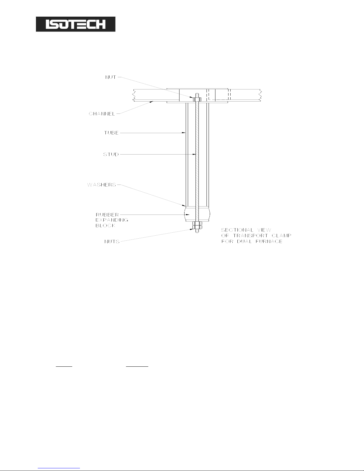
UNPACKING
EVERY EFFORT HAS BEEN MADE TO PACKAGE THIS UNIT FOR TRANSPORT AND TO ENSURE ITS GOOD
CONDITION ON ARRIVAL AT ITS DESTINATION.
BEFORE COMMISSIONING IT IS NECESSARY TO REMOVE THE FURNACE CORE TRANSIT CLAMP. TO AVOID
DAMAGE PLEASE FOLLOW INSTRUCTIONS:
1. Slacken the central nut using the required tube spanner; the insertion of a screwdriver through the tube
spanner will prevent the central stud turning.
2. Remove the 3 screws securing the transit clamp to the top of the unit. Slacken each screw by degrees
equally.
3. Gently lift the transit clamp vertically; the attached tube and rubber securing block will thereby be extracted
from the furnace core.
4. Normal commissioning procedure may now be followed.
5. Keep the transit clamp and use it if the furnace is ever transported.
Page 8

Page 8 of 40
Dual Furnace Models M17705, N17706 & 17707 Iss.09 – 12/14
SAFETY
CAUTIONARY NOTE
Products of Isothermal Technology Ltd are intended for technically trained and competent personnel familiar with
good laboratory practice. It is expected that personnel using this equipment will be knowledgeable and skilful in the
management of apparatus which may be under power or under extremes of temperature (molten metals, cryogenic
liquids, etc.) and will appreciate the hazards which may be associated with, and the precautions to be taken with,
such equipment.
THIS EQUIPMENT MUST BE EARTHED
The furnace is supplied with a fuse carrier fitted with a neutral link. This is clearly labelled and is for use with a mains
system with a neutral line, such as the UK supply. If the furnace is to be used on a system where both supply lines
are live with respect to earth then the neutral fuse link should be replaced with a fuse. A spare fuse is supplied with
the furnace.
FUSE AND NEUTRAL LINK REPLACEMENT
Hazardous voltages are exposed when the rear furnace panel is removed. Before removing the panel you must
isolate the furnace from the electrical supply. To replace the main electrical fuse or to replace the neutral link bar it
is necessary to remove the rear panel; see warning above. The panel will become free after the four corner screws
are removed.
The fuse holders will be seen at the lower right hand side of the cabinet. The black fuse holder will always contain a
fuse. The white fuse holder will leave Isotech with a neutral shorting bar. As explained elsewhere, if your local supply
does not have a neutral line but has both lines live with respect to earth this link should be replaced with a fuse and
the holder labelled to this effect.
The top half of the fuse carrier pulls free from the lower body.
Two spare fuses are supplied with the furnace; they are type A2 and have a rating of 10A for the low and medium
temperature furnace and 32A for the high temperature furnace.
Page 9

Page 9 of 40
Dual Furnace Models M17705, N17706 & 17707 Iss.09 – 12/14
INTRODUCTION
The Dual Furnace range of calibration apparatus comprises 3 models, all working on the same principle and having
the following features in common:
1. A rack for storage, at around room temperature, of up to 4 thermometers. Lined with ceramic board, the
rack will not be damaged if very hot thermometers are placed in it.
2. A furnace of diameter 50mm and depth 400mm which can be used to pre-warm or anneal up to 4
thermometers.
3. A pre-calibration pocket to install a single thermometer immediately prior to calibration or to house the
monitor thermometer between periods of use.
4. A heat-pipe furnace to create optimal conditions for an appropriate range of fixed point cells. The use of
freeze-point cells within the heat pipe is described in the manual which accompanies Isotech cells.
All 4 features are built into one cabinet, making the dual furnace a self-contained calibration facility.
Both component furnaces of the dual furnace can be fitted with communications interfaces for automated use.
Page 10

Page 10 of 40
Dual Furnace Models M17705, N17706 & 17707 Iss.09 – 12/14
THE 3 DUAL FURNACES
MODEL 17707
Contains a water heat pipe, giving an operational temperature range from 125°C to 250°C and thus making it an ideal
system for realisation of Indium and Tin freeze points.
Its annealing furnace has a temperature range from near ambient up to 700°C.
MODEL 17706
Contains a potassium heat pipe with a temperature range from 400°C to 1000°C, thus encompassing Zinc,
Aluminium and Silver freeze points.
Its annealing furnace has a temperature range from near ambient to 950°C.
MODEL 17705
Contains a sodium heat pipe with a temperature range from 450°C to 1100°C, thus constituting a facility for
Aluminium, Silver, Gold and Copper freeze point measurements.
Its annealing furnace has a temperature range from near ambient to 950°C.
Page 11

Page 11 of 40
Dual Furnace Models M17705, N17706 & 17707 Iss.09 – 12/14
OPERATIONAL CONVENIENCE
Until the advent of the dual furnace, the handling of thermometers was treated as a separate problem, or ignored.
With the dual furnace, thermometers can be stored, pre-warmed, calibrated and annealed in one comprehensive
facility, without introducing contamination or strain.
The two furnaces in each dual furnace have independent temperature controllers and independent adjustable overtemperature cut-outs for added security. These features are shown in the wiring diagram.
Page 12

Page 12 of 40
Dual Furnace Models M17705, N17706 & 17707 Iss.09 – 12/14
ACKNOWLEDGEMENT
The Isotech dual furnace owes its origin to Dr. P. Marcarino of Italy. His research and development solved many of
the problems of contamination and handling of high temperature thermometers.
Page 13

Page 13 of 40
Dual Furnace Models M17705, N17706 & 17707 Iss.09 – 12/14
COMMISSIONING
Connect the step down transformer to a suitable 230Vac supply.
Before connecting the unit to the mains power supply, check the impedance between live and earth, and neutral and
earth (values as low as 2MΩ on arrival are acceptable since moisture may be present after transportation).
Familiarise yourself with controller operation; manuals are supplied with all equipment.
Plug in and switch on the dual furnace (figure 1) and operate the reset button. This will energise the annealing
furnace controller. Adjust the set point to 100°C (450 and 500°C for potassium 17706 and Sodium 17705 models)
and the over-temperature controller set point to 50°C above the controller set point. After 1 or 2 hours the
annealing furnace will stabilise. Adjust its over-temperature set point downwards until the circuit relay trips,
switching off the annealing furnace.
Later models of the furnace use a Eurotherm over-temperature cut-off controller. On these models the RESET
button is located below the over-temperature controller. The SP value should be set approximately 50°C higher
than the operating controller setting. If this limit should be exceeded the red push button switch will reset the
apparatus once the furnace temperature has fallen below the AL1 value.
To turn on system power at start up (or as required), it is necessary to depress the red push button.
To adjust SP press the "Scroll" until the controller indicates “SP”.
Press the UP or DOWN keys to modify the SP value.
NOTE; the annealing/pre-heating furnace controller has been pre-set to produce a slow change in temperature, in
line with the heating and cooling rates recommended for annealing of thermometers. Do not over-ride the control
settings.
The recrystallised alumina liner has a closed end and thermometers may be placed directly into the liner for
annealing.
Switch on the main furnace (heat pipe) and press the reset button. This will energise the heater.
The rate of change of temperature for a heat-pipe at low temperature must be controlled, and for this reason the
heat-pipe controller has been pre-programmed to warm up slowly to its minimum working temperature. The
parameters used to effect this control are not directly accessible, for safety reasons.
As soon as the minimum temperature has been reached, the initial restriction on the rate of approach to set point is
removed.
The remainder of the instructions differ for the three models; reference should be made to the page clearly marked
with the appropriate dual furnace model.
Page 14

Page 14 of 40
Dual Furnace Models M17705, N17706 & 17707 Iss.09 – 12/14
MODEL 17707 WATER HEAT-PIPE FURNACE
FINAL PART OF THE COMMISSIONING INSTRUCTIONS
The heat up rate of the furnace is limited to ensure long life of the heat pipe.
Impose a heat pipe set point of 150°C and set the over-temperature controller to 200°C.
Allow 1 to 2 hours for the furnace to stabilise and then reduce the over-temperature cut-out setting until the relay
trips, thus switching off the furnace.
The 17707 furnace is now ready for use.
Page 15

Page 15 of 40
Dual Furnace Models M17705, N17706 & 17707 Iss.09 – 12/14
NEXT GENERATION CALIBRATION APPARATUS FOR INDIUM AND TIN
FIXED POINTS
INTRODUCTION
Before calibrating a standard platinum resistance thermometer, it is usual to check its water triple point resistance
value and then to anneal the thermometer. The annealing temperature varies typically between 400 and 700°C.
DESCRIPTION
The new calibration apparatus developed by Isotech not only allows you to create and maintain the ITS 90 freezing
points of Indium and Tin using a water heat-pipe, but also provides a second furnace for annealing thermometers at
temperatures up to 700°C.
Complementary features of the apparatus are a pre-heating tube, maintained at the cell temperature, and a rack for
storage of up to 4 thermometers at approximately ambient temperature.
METHOD OF OPERATION
1. By adjusting the set-point to a few degrees above the appropriate melting point, the cell, (tin or indium) is
melted in the essentially temperature-gradient-free water-filled heat-pipe. When the cell's contents are
completely melted, the heat-pipe temperature is re-adjusted to a level 0.5°C below the freeze temperature
of the cell. When this set-point has been reached, a cold rod is introduced into the re-entrant tube of the cell
to initiate the freeze, giving a plateau that can be maintained for between 12 and 24 hours. A modified
technique is appropriate for tin, in the form of an applied thermal shock to the whole cell to counteract the
tendency for a slow, large undercool to occur.
2. The thermometers are removed from their rack and, assuming they have already been annealed and are
stable, are placed successively in the pre-warming tube for 5 minutes and then transferred to the cell for
calibration. After 20 to 30 minutes the thermometer can be removed slowly from the cell and, after cooling
to room temperature, the R
TPW
-value can be checked.
Page 16

Page 16 of 40
Dual Furnace Models M17705, N17706 & 17707 Iss.09 – 12/14
SPECIFICATION
Dimensions of the cabinet containing the apparatus are:
Width: 600mm
Depth: 560mm
Height: 960mm (excluding thermometer storage rack)
Control: The heat-pipe and the annealing furnace are controlled independently to a resolution of
0.1°C.
Communications: RS422
Temperature range: 120°C to 250°C.
Over-temperature Provided on each furnace and operated by an independent sensor.
protection:
Supply: 2kW, 220-240V, 50/60Hz.
(110-120V to special order)
Performance: Essentially temperature-gradient-free heat-pipes provide the ideal apparatus for fixed point
calibration and give a virtually perfect freezing profile within the fixed point cell.
The addition of the second furnace enables thermometers to be stabilised before calibration,
by annealing out strain and removing any 3D oxides.
A comprehensive manual accompanies each apparatus.
Reproducibility of the temperatures of freezing indium or tin is typically ±0.1mK with Isotech fixed point cells.
HOW TO ORDER
Ask for Model 17707. We need to know your voltage and whether you require communications. A temperature
equalising block is an available option (for comparison calibration purposes).
PLEASE NOTE: You may wish to purchase cells and thermometers with this apparatus. Both are available from
Isotech. Next Generation Apparatus is also available for Zinc, Aluminium Silver and Copper fixed points. Please ask
for data sheets 17705 and 17706.
Page 17

Page 17 of 40
Dual Furnace Models M17705, N17706 & 17707 Iss.09 – 12/14
THE POTASSIUM HEAT-PIPE FURNACE, MODEL 17706
FINAL PART OF THE COMMISSIONING INSTRUCTIONS
The initial slow temperature ramp is maintained until the temperature reaches 400°C.
Impose a heat-pipe set-point of 420°C and set the over-temperature controller to 450°C. Allow 1 to 2 hours for the
furnace to stabilise and then reduce the over-temperature cut-out setting until the relay trips, thus switching off the
furnace.
Allow the furnace to cool and isolate it from the electricity supply.
At the rear are two water connections; these should be connected to a controllable supply and a flow of 1 to 2 litres
of water per minute established - this prevents the top of the cabinet being over-heated at high furnace
temperatures. Run the water for 1 hour to check the furnace for absence of leaks (the floor underneath the cabinet
should be inspected).
The 17706 furnace is now ready for use.
Page 18

Page 18 of 40
Dual Furnace Models M17705, N17706 & 17707 Iss.09 – 12/14
NEXT GENERATION CALIBRATION APPARATUS FOR ZINC, ALUMINIUM
AND SILVER FIXED POINTS
INTRODUCTION
Using high temperature thermometers presents many problems due to strain and contamination, which can very
easily be introduced into the thermometer during thermal cycling.
Limited understanding of the relevant mechanisms has resulted in a dearth of published information and of available
apparatus for the safe treatment of these sophisticated devices.
DESCRIPTION
Sufficient information now exists at Isotech to allow introduction of a new apparatus, specifically designed not only to
realise and maintain the ITS 90 fixed points of Zinc, Aluminium and Silver, but also to pre- and post-condition the
thermometers to be calibrated. To this end a second furnace has been incorporated, which, because of its design,
will permit conditioning to be carried out safely and without introducing contaminants into thermometers.
Complementary features of the apparatus are a pre-calibration tube (held at the temperature of the fixed point)
made of a unique and gas tight material, together with a rack for storage of up to 4 thermometers at approximately
ambient temperature.
METHOD OF OPERATION
1. By adjusting set-point to a few degrees above the appropriate melting point, the cell (zinc, aluminium or
silver) is melted in an essentially temperature gradient free potassium-filled heat-pipe. When melting is
complete, the heat-pipe temperature is readjusted to a level 0.5°C below the freeze temperature of the cell.
When this set-point has been reached a cold rod is introduced into the re-entrant tube of the cell to initiate
the freeze, giving a plateau that can be maintained for between 12 and 24 hours.
2. The thermometers are removed from their storage rack and placed in the pre-conditioning furnace. The
furnace is slowly heated to 400°C (if the cell is Zinc), 650°C (for Aluminium) or 900°C (for Silver).
During conditioning, thermometers are protected from contamination by a slow air flux around them.
CAUTION: it is essential, when thermometers are inserted into furnaces, to keep their heads cool. This can
be accomplished by blowing air, at ambient temperature, across them by means of a free-standing fan.
3. Thermometers are transferred individually to the cell for 20 to 30 minutes, for calibration, and then returned
to the post-conditioning furnace.
4. When all the thermometers have been calibrated, the post-annealing furnace is slowly cooled to 450°C after
which they can safely be exposed to room temperature and, thereafter, measured at the triple point of
water.
Throughout the time the thermometers are above 450°C the temperature changes are slow enough to
prevent strain, and the slow flow of air prevents contamination at high temperatures.
Page 19

Page 19 of 40
Dual Furnace Models M17705, N17706 & 17707 Iss.09 – 12/14
SPECIFICATION
Dimensions of the cabinet containing the apparatus are:
Width: 600mm
Depth: 560mm
Height: 960mm (excluding thermometer storage rack)
Control: The heat-pipe and the thermometer furnace are controlled independently to a resolution of
0.1°C.
Communications: RS422
Over-temperature Provided on each furnace and operated by an independent sensor.
Protection:
Temperature range: 400 to 1000°C.
Power: 3kW, 110V, 50/60Hz
Performance: Essentially temperature gradient-free heat-pipes provide the ideal apparatus for fixed point
calibration and give a virtually perfect freezing profile within the fixed point cell.
The addition of the second furnace, with its air-flow, enables thermometers to be easily and
safely calibrated.
A comprehensive manual accompanies each delivery.
Page 20

Page 20 of 40
Dual Furnace Models M17705, N17706 & 17707 Iss.09 – 12/14
THE SODIUM HEAT-PIPE FURNACE, MODEL 17705
FINAL PART OF THE COMMISSIONING INSTRUCTIONS
The initial slow temperature ramp is maintained until the temperature reaches 450°C. Impose a heat-pipe set-point
of 500°C and set the over-temperature controller to 550°C. Allow 1 to 2 hours for the furnace to stabilise and then
reduce the over-temperature cut-out setting until the relay trips and thus switching off the furnace.
Allow the furnace to cool and isolate it from the electricity supply.
At the rear are two water connections; these should be connected to a controllable supply and a flow of 1 to 2 litres
of water per minute established - this prevents the top of the cabinet being overheated at high furnace temperatures.
Run the water for 1 hour to check the furnace for absence of leaks (the floor underneath the cabinet should be
inspected).
The 17705 furnace is now ready for use.
N.B. The sodium heat-pipe incorporated in Model 17705 has a life of about 1000 hours at 1100°C, limited by the
Inconel containment.
It should endure operation for at least 10,000 hours at 1000°C.
Page 21

Page 21 of 40
Dual Furnace Models M17705, N17706 & 17707 Iss.09 – 12/14
NEXT GENERATION CALIBRATION APPARATUS FOR ALUMINIUM, SILVER
AND COPPER FIXED POINTS
INTRODUCTION
Using high temperature thermometers presents many problems due to strain and contamination which can very
easily be induced into the thermometer during temperature cycling.
Limited understanding of the relevant mechanisms has resulted in a dearth of published information and of available
apparatus for the safe treatment of these sophisticated devices.
DESCRIPTION
Sufficient information now exists at Isotech to allow introduction of a new apparatus, specifically designed not only to
realise and maintain the ITS 90 fixed points of Aluminium, Silver and Copper, but (housed in the same facility)
incorporating a second furnace which, because of its design, can be used safely and without contamination, to preheat and anneal the thermometers for calibration.
Complementary features of the apparatus are a pre-calibration tube (held at the temperature of the fixed point)
made of a unique and gas tight material, together with a rack for storage of up to 4 thermometers at approximately
ambient temperature.
METHOD OF OPERATION
CAUTION: it is essential, when thermometers are inserted into furnaces, to keep their heads cool. This can be
accomplished by blowing air, at ambient temperature, across them by means of a free-standing fan.
1. By adjusting the set-point to a few degrees above the appropriate melting point, the cell (aluminium, silver or
copper) is melted in an essentially temperature-gradient-free sodium-filled heat-pipe. When melting is
complete, the heat-pipe temperature is re-adjusted to a level 0.5°C to 1°C below the freeze temperature of
the cell. When this temperature has been reached a cold rod is introduced into the re-entrant tube of the
cell to initiate the freeze, giving a plateau that can be maintained for between 12 and 24 hours.
2. The thermometers are removed from their storage rack and placed in the pre-heating furnace. The furnace
is slowly heated to 600°C (if the cell is Aluminium) and 900 or 950°C (if the cell is Silver or Copper).
During conditioning, thermometers are protected from contamination by a slow air flux around them.
3. Thermometers are transferred individually to the cell for 20 to 30 minutes, for calibration and then returned
to the annealing furnace.
4. When all the thermometers have been calibrated and have been returned to the annealing furnace, they are
slowly cooled to 450°C at which stage they can safely be exposed to room temperature and, when cool,
measured at the triple point of water. Throughout the time the thermometers are above 450°C
temperature changes are slow, which prevents strain and the flow of air prevents contamination at high
temperatures.
Page 22

Page 22 of 40
Dual Furnace Models M17705, N17706 & 17707 Iss.09 – 12/14
SPECIFICATION
Dimensions of the cabinet containing the apparatus are:
Width: 600mm
Depth: 560mm
Height: 960mm (excluding thermometer storage rack)
Control: The heat-pipe and the thermometer furnace are controlled independently to a resolution of
0.1°C.
Communications: RS422
Over-temperature Provided on each furnace and operated by an independent sensor.
Protection:
Temperature range: 450 to 1100°C.
Power: 3kW, 220-240V, 50/60Hz
(110-120V to special order)
Performance: Essentially temperature-gradient-free heat-pipes provide the ideal apparatus for fixed point
calibration and give a virtually perfect freezing profile within the fixed point cell.
The addition of the second furnace with its air-flow enables thermometers to be easily and
safely calibrated.
A comprehensive manual accompanies each delivery.
Page 23

Page 23 of 40
Dual Furnace Models M17705, N17706 & 17707 Iss.09 – 12/14
ELIMINATING CONTAMINATION DURING THE CALIBRATION OF HIGH
TEMPERATURE THERMOMETERS
It is quite feasible to heat a high temperature thermometer to 1000°C and return it to ambient temperature without
altering the water triple point resistance value by more than 0.5mK equivalent.
Instructions in the Isotech 962 and 96178 thermometer manuals explain how to handle and keep clean the
thermometers. It is imperative that procedures are followed because contaminants can penetrate and pass through
physically-intact quartz sheaths at temperatures above 800°C.
To prevent this happening, a secondary containment has been provided, in kit form that can be fitted to dual furnace
Models 17705 and 17706.
The completed assembly is depicted below:
ANNEALING COMPONENT OF THE DUAL FURNACE SHOWING AIR FLOW
Air percolates through the quartz wool, oxidising any pollutants and rendering them harmless and unable to
penetrate the quartz sheath of the thermometer.
The combination of air-flow and positioning ensures that thermometers will not become contaminated at high
temperature.
The dual furnace also has a pre-calibration tube made of silicon carbide, which justifies its high cost by remaining
impervious to all gases that would poison the high temperature thermometer. The pre-calibration tube can be used
not only to store each thermometer immediately prior to calibration but also to house the standard thermometer
used to monitor the cell's plateau at various stages in a calibration schedule.
Page 24

Page 24 of 40
Dual Furnace Models M17705, N17706 & 17707 Iss.09 – 12/14
Optional equipment includes an equalising block that fits in the heat-pipe so that the furnace can be used as a
gradient-free comparison facility. Please note that the temperature-equalising block is for use up to 700°C only.
Above 700°C the sensors to be calibrated may be immersed directly into the heat-pipe without using an equalising
block.
IMPORTANT NOTE: Since the calibration of sensors at high temperatures can be fraught with difficulties, if any
doubt exists, please consult Isotech for advice before embarking on any exercise in which there is a risk of
contamination of the sensors you are trying to calibrate.
Page 25

Page 25 of 40
Dual Furnace Models M17705, N17706 & 17707 Iss.09 – 12/14
MAINTENANCE
Unless damaged in transit, the apparatus should operate for many years without maintenance or fault.
It has been common practice in the past to list a number of possible fault modes and corrective actions. However,
our experience suggests that the very low incidence of failure almost implies modes not encountered previously and,
therefore, not easy to envisage before-hand.
Therefore, we now prefer to work differently. With international communications so good these days, if anything
goes wrong with the apparatus or you need any other after sales service, just contact Isotech or the agent from
whom you purchased the apparatus. On our help-line we are anxious to serve you and will swiftly be able to help
you solve your problem, or deal with a technical enquiry.
Page 26

Page 26 of 40
Dual Furnace Models M17705, N17706 & 17707 Iss.09 – 12/14
SPARE PARTS
Chopped Bulk Fibre (kg) 932-20-18
32A Fuse A1 935-12-48
A2 Black Fuse Holder 935-11-09
45 amp Opto Relay 935-21-19
110V Contactor 935-21-18
110V Rocker Switch 935-27-02B
N Thermocouple 935-14-42
White Fuse Holder 935-11-10
Inconel Cell Basket 410-03-00A
Ceramic Bricks 935-29-02
Silicon Carbide Tube (Sodium/Potassium) 935-29-20
Pre-heat Tube (Water) 420-03-22
Page 27

Page 27 of 40
Dual Furnace Models M17705, N17706 & 17707 Iss.09 – 12/14
CELL HANDLING
In order to facilitate introduction to, and removal from the furnace, Isotech can provide for each cell, supplementary
equipment largely comprising an Inconel basket with detachable handle.
To prevent the cell-surface becoming discoloured, it is recommended that, before using the cell, the basket and
insulation be placed in the furnace and the furnace be taken to above the cell working temperature for at least 2
hours. This operation outgases the basket and insulation, which may smoke and discolour during this first
temperature excursion. The cell can then be inserted into the basket in readiness for use. If removing the cell with a
thermometer in its pocket (e.g. tin cell), extreme caution is necessary in applying support by means of the
diametrically-pivoted handle. The handle will need to be maintained in a non-vertical plane while being used for
removing and replacing the assembly.
CELL KIT
Basket, handles, discs of ceramic insulation, Inconel baffles and platinum foil discs if required.
Sketches show the recommended assembly of the cell basket (and insulation discs) in a furnace core.
Page 28

Page 28 of 40
Dual Furnace Models M17705, N17706 & 17707 Iss.09 – 12/14
Page 29

Page 29 of 40
Dual Furnace Models M17705, N17706 & 17707 Iss.09 – 12/14
Page 30

Page 30 of 40
Dual Furnace Models M17705, N17706 & 17707 Iss.09 – 12/14
Page 31

Page 31 of 40
Dual Furnace Models M17705, N17706 & 17707 Iss.09 – 12/14
THERMOMETRIC FIXED POINTS; A TUTORIAL
The International Temperature Scale, the scale most used in science and industry, is based on a series of fixed point
temperatures. Fixed points involve two-phase or three-phase equilibria of, ideally, pure materials to which constant
temperature values have been assigned by primary thermometry. Defining fixed points are chosen to be as few in
number as is consistent with the need to establish satisfactory interpolation procedures.
There are secondary reference points which, also, are two-phase or three-phase equilibria of very pure materials,
whose temperature values have been established by measurements made with interpolation instruments calibrated
at the defining fixed points. Secondary reference points are useful for the calibration of thermometers having total
ranges shorter than the interpolation ranges of the Scale. Generally, secondary points are admitted to the Scale only
if the material is generally available in high purity and if sufficient reproducibility of the equilibrium temperature has
been confirmed by measurements made independently by a considerable number of investigators. An average value
(weighted according to individual uncertainties) is then used as the ITS temperature value.
Two-phase equilibria may be solid-liquid, liquid-vapour, or solid-vapour. From the Phase Rule of Gibbs:
P + F = C + 2
P is an integer equal to the number of phases present, C is the number of components present - for a pure material
C = 1 - and F is an integer representing the number of degrees of freedom. It is evident that the temperatures of
two-phase equilibria are pressure-dependent (one degree of freedom only) whereas equilibria in which all three
phases are present (triple points) are characterised by unique values of temperature and pressure (zero degrees of
freedom).
A necessary condition to establish a triple point is to contain the appropriate material in a sealed enclosure from
which all other materials, including air, have been evacuated, leaving a space to be filled by the vapour phase at a
pressure appropriate to the temperature. When the three-phase (solid, liquid, vapour) condition has been
established, these parameters will settle to their unique triple-point values.
The defining fixed points above 0°C are liquid-solid equilibria of high-purity metals. Pressure-dependence is small and
thermal capacity and thermal conductivity are relatively high. Metals are generally available with a purity of 99.999%
("five-nines") or 99.9999% ("six-nines").
Figure 2 shows the design of a cell for realising the liquid-solid equilibrium of pure metal. The metal is contained in a
crucible of purified graphite, with a graphite cover and a graphite re-entrant sleeve. The crucible is enclosed in an
envelope of fused quartz, which extends into the sleeve interior to form the thermometer well. The cell is charged
with a pure metal, purged and filled with sufficient argon (or another inert gas) to give a pressure of 101kPa (1
standard atmosphere) at the freezing temperature and then sealed. Thus it is at once protected from contamination
and supplied with an inert atmosphere at the required pressure at the equilibrium temperature. A correction for the
effect of change in ambient pressure on freezing point need not be made. Sealed cells of this type have shown no
measurable change after 15 years of use.
In general, sealed fixed-point cells are used in vertical-tube furnaces which provide good temperature control and
sufficient cell immersion to make axial temperature gradients, in the measurement zone, negligible. With the cell in
the furnace, the controller is first set about 5°C above the anticipated value corresponding to the melting
temperature of the metal in the cell. The onset of melting is indicated by a cessation of temperature rise because of
the latent heat required to produce the phase change. This melt plateau can last for a considerable period of time.
When melting is complete, the cell temperature will rise to the furnace temperature.
Page 32

Page 32 of 40
Dual Furnace Models M17705, N17706 & 17707 Iss.09 – 12/14
The furnace temperature is then reduced to a value slightly below the melt temperature. The temperature falls until
the first solid nucleus of metal is formed, at which stage the temperature drop is arrested. With both liquid and solid
metal present in the cell, a constant temperature is maintained by the latent heat released by the freezing metal. The
controller temperature setting will cause the rate of heat egress from the cell to be relatively low, thus generating a
freeze plateau that can usually be maintained for a number of hours, during which time thermometers may be
calibrated.
A variation on this is the establishment of the triple point of mercury. Since this temperature is below normal
ambient, the apparatus in which the point is realised must provide refrigeration as well as controlled heat. A separate
manual describes the use of this apparatus.
Another variation is the realisation of the melting point of gallium. This metal is used on the melt plateau rather than
on the freeze plateau. A separate manual describes the use of the apparatus for realising this fixed point.
There are, unfortunately, no convenient metal freeze points or triple points at the cryogenic end of the Scale. The
defining point applicable to long stem thermometers at the low end of their useful range is the triple point of argon.
In practice, the difficulties of setting up conditions to facilitate this measurement can conveniently be circumvented by
carrying out the alternative procedure of comparison calibration, in which the thermometer is compared, in an
environment of boiling nitrogen, to a similar thermometer which possesses a calibration traceable to national
standards. A separate manual describes the nitrogen boiling point apparatus.
The temperature at which the change of phase occurs at atmospheric pressure is specific to the upper, exposed,
surface of the metal. However, it is not feasible (because of the temperature gradient in this locality of the
thermometer well) to obtain an accurate measurement under this condition. The closest approach to temperature
uniformity demands insertion of the thermometer to the foot of the well with the consequence that the change-ofphase temperature measured is influenced by the static pressure head of the column of metal above the effective
level of the thermometer sensing element.
Corrections that are used to enable measured phase-change temperatures to be converted to values that would
pertain at 1 standard atmosphere pressure, for the various metals (and for mercury and water at their triple points),
are given in the table. For a given column height (of the order of 200mm for Isotech sealed freeze point cells), the
correction will be proportional to metal density and to a coefficient expressing the sensitivity to pressure of the
phase-change temperature. The sign of this coefficient will depend on whether the metal contracts or expands on
freezing.
Page 33

Page 33 of 40
Dual Furnace Models M17705, N17706 & 17707 Iss.09 – 12/14
DEFINING FIXED POINTS AND RELATED DATA
FIXED
POINT
ITS 90 TEMPERATURE
PRESSURE COEFFICIENT
ITL CELL
DESIGNATION
SUITABLE
APPARATUS
FOR CELL
OPERATION
°C
K
mK/
bar
mK/m HEAD OF
SUBSTANCE
ARGON
TP
-189.3442
83.8058
(NOT
AVAILABLE
FROM ITL)
MERCURY
TP
-38.8344
234.3156
+5.4
+7.1
ITL-M-17724
ITL-M-17725
WATER
TP
0.01
273.16
-7.5
-0.73
A11/50 or B11/50
ITL-M-18233
GALLIUM
MP
29.7646
302.9146
-2.0
-1.2
ITL-M-17401
ITL-M-17402A
INDIUM
FP
156.5985
429.7485
+4.9
+3.3
ITL-M-17668
ITL-M-
17701/3/4/7
TIN
FP
231.928
505.078
+3.3
+2.2
ITL-M-17669
ITL-M-
17701/3/4/7
ZINC
FP
419.527
692.677
+4.3
+2.7
ITL-M-17671
ITL-M-
17701/2*/3/6
ALUMINIUM
FP
660.323
933.473
+7.0
+1.6
ITL-M-17672
ITL-M-
17702**/5/6
SILVER
FP
961.78
1234.93
+6.0
+5.4
ITL-M-17673
ITL-M-
17702**/5/6
NOTES:
1. TP = Triple Point, MP = Melting Point, FP = Freezing Point
2. Pressure corrections that apply to triple point and to other sealed-cell measurements are determined solely
by the pressure head of material in the cell; variability of atmospheric pressure has no effect on the
measurements.
* Furnace with potassium heat-pipe for zinc freezing point.
** Furnace with either potassium or sodium heat-pipe at aluminium and silver freezing points.
Page 34

Page 34 of 40
Dual Furnace Models M17705, N17706 & 17707 Iss.09 – 12/14
GENERAL NOTE ON ISOTECH METAL FREEZE POINT CELLS
Isotech freeze point cells contain metal that is 99.9999+% pure, except that aluminium cells may be filled with metal
not less than 99.999% pure, depending upon the availability of aluminium in suitable physical form.
The metal is contained in crucibles of high-purity graphite. After machining the graphite, any residual metal oxides
are removed by exposure to fluorine at a very high temperature. Graphite, even of high density, cannot be
guaranteed to be non-microsporous. Some cells, in preparation or after use, will be seen to exude droplets or
spicules of the contained metal on to the outer surface of the graphite crucible; some may show a film of metal. This
is considered not to be a defect of the cell; it does not reduce its useful life nor change its equilibrium plateau
temperature.
The cell is a fragile device. Although it is as rugged as is consistent with its materials and purpose, it must still be
regarded as a kilogram, or more, of mass, loosely contained in a frangible shell. Cells should never be inverted,
although they may be slowly turned to the horizontal and laid on their sides. Transporting cells by common carrier is
not recommended and, as furnished, they must be hand-carried. A broken cell cannot, in general, be repaired,
although a cell which is broken but sufficiently intact to contain its metal can be used for some time if contamination is
avoided.
Each cell can be supplied with an Inconel container or basket 400mm (16") in length, in which the cell should be
placed to facilitate removal from the furnace. The basket has two diametrically-opposite holes near its upper end in
which a wire handle of suitable material (for example, 14 SWG Nichrome) may be temporarily attached. It is urged
that the basket always be used with tin cells, because the recommended practice includes removal of the cell from
the furnace as part of the freeze cycle.
Page 35

Page 35 of 40
Dual Furnace Models M17705, N17706 & 17707 Iss.09 – 12/14
PRECAUTIONS TO PREVENT DEVITRIFICATION OF QUARTZ ENVELOPES
The crucibles (containing the metal) of Isotech sealed fixed point cells are encased in an envelope of pure fused
quartz, whose purpose is to avoid contamination of the enclosed metal, by foreign metal ions or oxygen. To this end,
it contains an inert gas whose pressure is 1 standard atmosphere at the metal freezing temperature.
Fused quartz is vitreous in nature but, like other glasses, can be stimulated to crystallise (devitrify) by external
influences at high temperatures. The crystalline form is recognisable as a localised cloudy or milky appearance.
Devitrification is progressive and irreversible.
Quartz glass which is the glass used to cover the Silver and Copper Cells has an annealing (softening) temperature of
1050°C. Some 35°C below the Copper Melt Point.
A user should not therefore be surprised if his Copper Cell begins to devitrify at these elevated temperatures.
A devitrified cell can no longer be assumed to be gas-tight. It may leak its enclosed gas and atmospheric air may leak
into it. The pressure at the freeze point may, as a consequence, be incorrect and, more seriously, contamination
may occur.
Silver and especially Copper Cells should be regularly checked by immersing them in clean hot water to make sure
there are no leaks.
If a leak is detected the cell should be returned to Isotech for a new Quartz cover.
Sealed quartz cells can be used for thousands of hours without devitrification if precautions are taken to ensure that
the outside surface is scrupulously clean before raising them to temperature. Any surface dirt, a water spot or a
single fingerprint is a potential seed for devitrification. Before exposing to high temperature the exterior of the cell
should be cleaned with a suitable alcohol such as Ethanol and then thoroughly wiped dry with clean tissue. (Similarly
SPRT’s to be inserted into the cell’s re-entrant tube should be previously cleaned in this way).
It is advisable to handle cells with clean cloth gloves.
The precaution applies particularly to cells for use at temperatures in excess of 500°C, although Isotech advises that
all cells be carefully cleaned before use.
Page 36

Page 36 of 40
Dual Furnace Models M17705, N17706 & 17707 Iss.09 – 12/14
GENERAL COMMENT
The use of freeze-point cells embodies one of nature's simplest and most predictable phenomena. However, the
technique (requiring association of cells with other equipment) involves subtlety and operator sensitivity. Before
relying upon measurements made in them, the operator should perform enough freezes to become familiar with the
cell, furnace, control, monitoring thermometer and readout (as a system) to ensure that the melt is clearly identifiable
and sufficiently consistent.
Page 37

Page 37 of 40
Dual Furnace Models M17705, N17706 & 17707 Iss.09 – 12/14
ADDITIONAL SERVICES AND INFORMATION
Isotech operates one of the world's most comprehensive UKAS supervised Laboratories.
Training is available to customers at an agreed daily rate.
The Isothermal Journal of Thermometry is a must for all Laboratory Managers and is on subscription.
Page 38

Page 38 of 40
Dual Furnace Models M17705, N17706 & 17707 Iss.09 – 12/14
FIGURE 1; SECTION THROUGH DUAL FURNACE
Page 39

Page 39 of 40
Dual Furnace Models M17705, N17706 & 17707 Iss.09 – 12/14
FIGURE 2; SEALED METAL FREEZING POINT CELL
A High-purity graphite crucible and cover
B High-purity graphite sleeve
C High-purity metal
D Fused-quartz envelope, filled to give a pressure of 1 standard atmosphere at the metal freezing temperature.
Page 40

Page 40 of 40
Dual Furnace Models M17705, N17706 & 17707 Iss.09 – 12/14
FIGURE 3; SEALED METAL FREEZING POINT CELL BODY DIMENSIONS
 Loading...