

Page 1
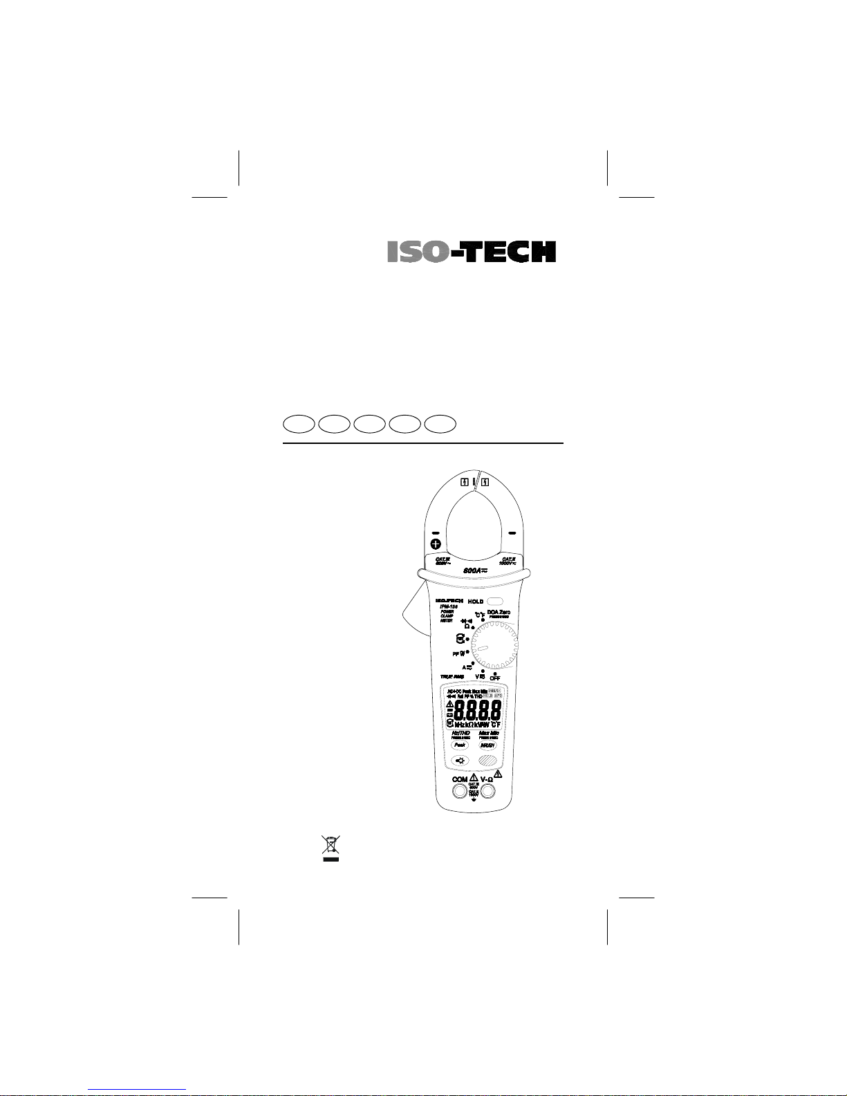
Instruction Manual
IPM 138
Clamp Multimeter
EN DE ES IT FR
Page 2

EN-2
Safety Information
Read and understand this Instruction Manual completely
before using this instrument. Failure to observe the warnings
and cautions in this Instruction Manual may result in injury or
death, or damage to the instrument and other equipment or
property.
If this instrument is used in a manner not specified in these
instructions, the protection provided by the instrument may be
impaired.
WARNING
- Examine the instrument an d pr obes an d lead s before use .
Do not use the instrument if it is wet or damaged, or if you
suspect it is not operating correctly.
- When using the instrument, t est lead s or pro bes, keep your
fingers behind the finger guards.
- Remove the test lead from the instrument before opening the
battery cover or instrument case.
- Always use the correct terminals, switch position and range
for measurements.
- Verify the instrument is oper at ing cor re ct ly by measu rin g a
known voltage before use. If in doubt, have the instrument
serviced.
- Do not apply more than the rated voltage as marked on the
instrument between terminals, or between any terminal and
earth ground.
- Use caution when measuring voltages above 30 Vac rms or
60 Vdc. These voltages pose a shock hazard.
- To avoid incorrect readings that can lead to electric shock,
replace the battery as soon as low battery indicator
appears in the display.
- Disconnect the circuit power and discharge all high-voltage
capacitors before making resistance, continuity, or diode
measurements.
- Do not use the instrument in a Hazardous Area or around
explosive gasses or vapours.
- Wear suitable Personal Protective Equipment when working
around or near hazardous Live conductors which could be
accessible.
- Do not use the th er mo cou p l e to m e a sur e t he t e mp erature of
Hazardous Live conductors or equipment.
Caution
- Disconnect the test leads from the test points before changing
the position of the function rotary switch.
- Never connect the instrument to a source of voltage with the
function rotary switch in Ω/
</ A position.
Page 3
EN-3
- If possible, do not work alone, so assistance can be given if
required.
- Do not expose the instrument to extremes of temperature or
high humidity.
- If this instrument is used in the vicinity of equipment which
generates electro magnetic interference, the display may
become unstable or the measurements may be subject to
large errors.
- Do not take temperature measurements immediately after
taking high voltage measurements as the accuracy of
measurements may be impaired. Allow a minimum of 5 min utes for the instrument to stabilize before taking temperature
measurements.
The following symbols may appear on the
instrument and in this Instruction Manual:
Maintenance
Do not attempt to repair this Instrument. It contains no userserviceable parts. Repair or servicing should only be performed
by qualified personnel. This instrument should be calibrated
yearly, or more frequently if u sed in harsh cond itio ns or if it is
suspected of being inaccurate.
For calibration and repair contact RS Components - the
address is given at the end of these instructions.
Cleaning
Periodically wipe the case with a damp cloth and detergent.
Do not use abrasives or solvents.
Risk of electric shock
Refer to Instruction Manua l
Direct Current (dc)
Alternating Current (ac)
=
Battery
Earth
Equipment protected throughout by double or reinforced
insulation
Conforms to EU directives
Dispose of this equipment in accordance with local
regulations.
F
Application around and removal from hazardous Live
conductors is permitted.
Page 4
EN-4
Power On/ Off
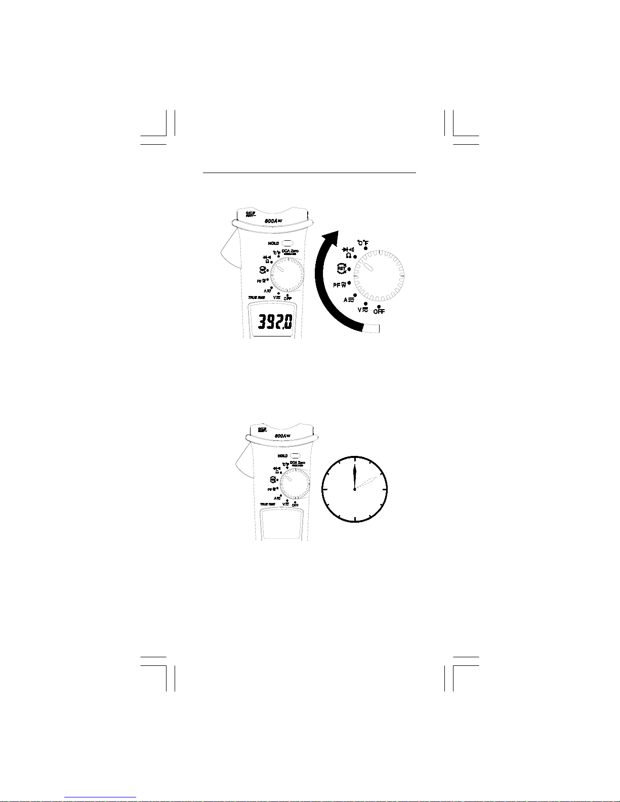
Auto Power Off
The Auto Power-off function will turn the instrument off
approximately 10 minutes after the last operation. To turn the
instrument on again, turn the rotary switch to the off position
and then back to the required function.
10min
To disable the Auto Power-off function:
Turn the instrument off, press and hold the “PEAK” button and
turn the rotary switch to the required function. The “APO”
symbol will not appear in the display. The auto Power-off is
disabled until the next time the instrument is turned off and on
again.
Page 5
EN-5
- If the measured voltage is greater than 42 V DC or AC RMS ,
the display will show "" and the buzzer beeps three times.
- If the measured voltage exceeds 1000 V DC or AC RMS, the
display will show "OL".
- If the measured frequency exceeds 1000 Hz , the display
will show " out. F ".
1. VOLTAGE /CURRENT Measurement
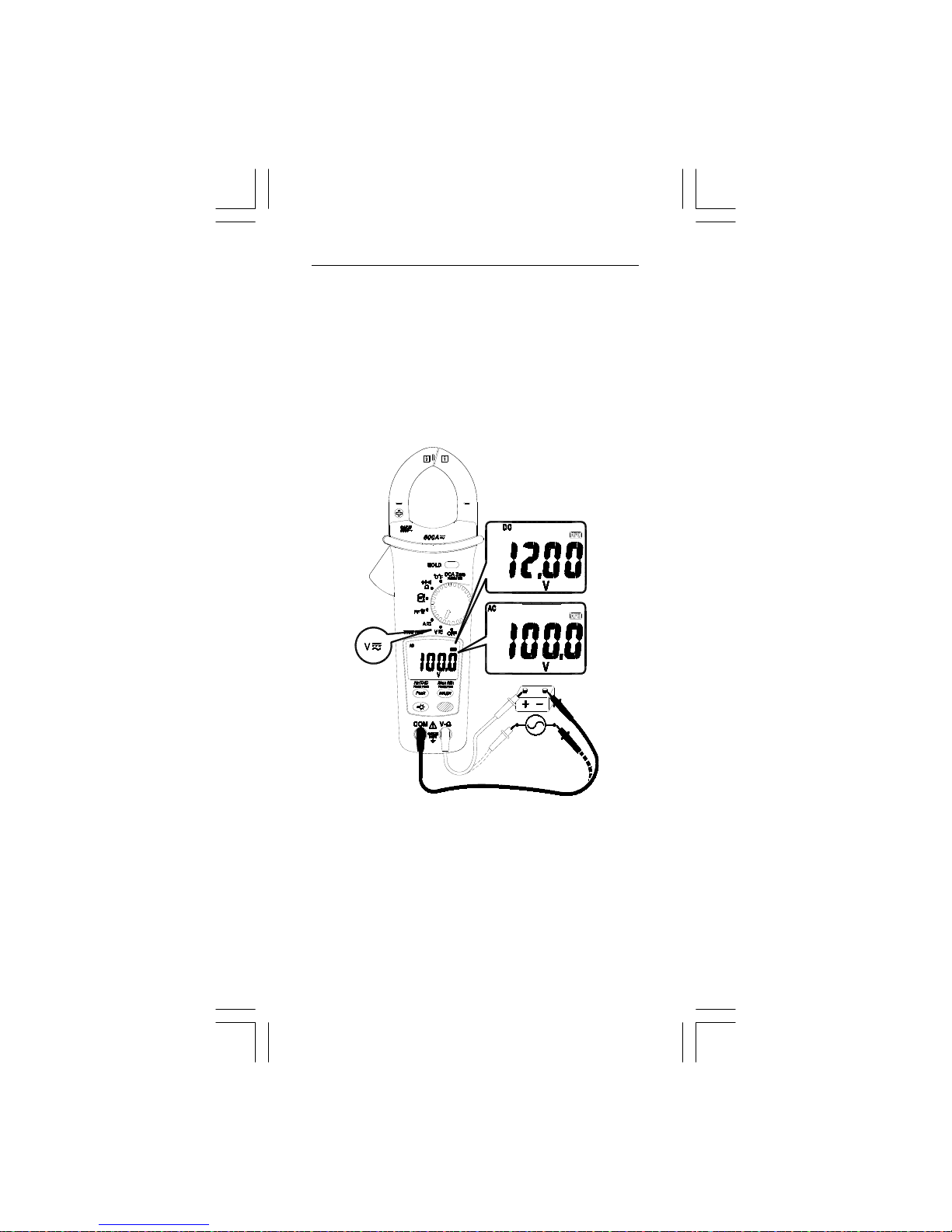
1-1 Voltage testing procedures
1. Plug the Black test lead into the COM terminal and the
Red test lead into the V-Ω terminal.
2. Set the rotary switch to the VB position.
3. Connect the test leads to the device to be measured.
4. Read the value from digital display.
Page 6
EN-6
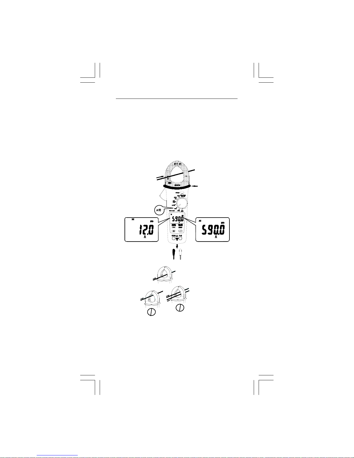
1-2 Current testing procedure
Note : Do not clamp the jaws around a conductor while the
instrument power is on.
1. Press the trigger to open the transformer jaws and clamp
around one conductor only. Ensure the jaw is firmly closed
around the conductor.
2. Set the rotary switch to the AB position.
3. Read the value from digital display.
I
I
I
I
OK
OK
OK
I + (-I) = 0
- If the measured current exceeds 620 A DC or AC RMS,
the display will show "OL" .
- If the measured frequency exceeds 1000Hz , the display
will show " out. F ".
1
2
A
5
9
0
A
CAT.Ⅲ.600V
with respect to
earth for the jaw.
Barrier for
Hand Guard
Do not hold
the meter across
the Barrier
Page 7
EN-7
1-3 Button Function
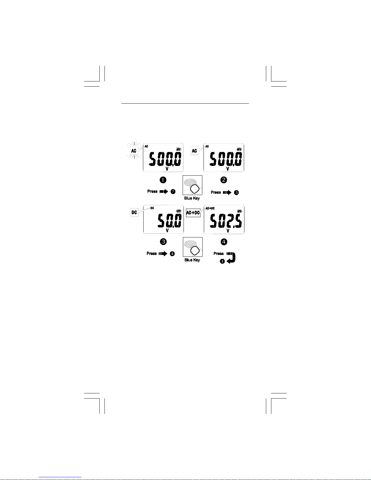
1-3-1 BLUE BUTTON: Press the Blue button to choose
Auto AC or DC, AC, DC, or AC+DC measurement.
n Auto AC/DC mode (AC or DC flashing):
The displayed value will be the AC only RMS value or the
DC value, whichever is greater.
o AC mode : AC only with RMS value.
p DC mode : DC value.
q AC+DC mode : AC+DC RMS value.
Page 8
EN-8
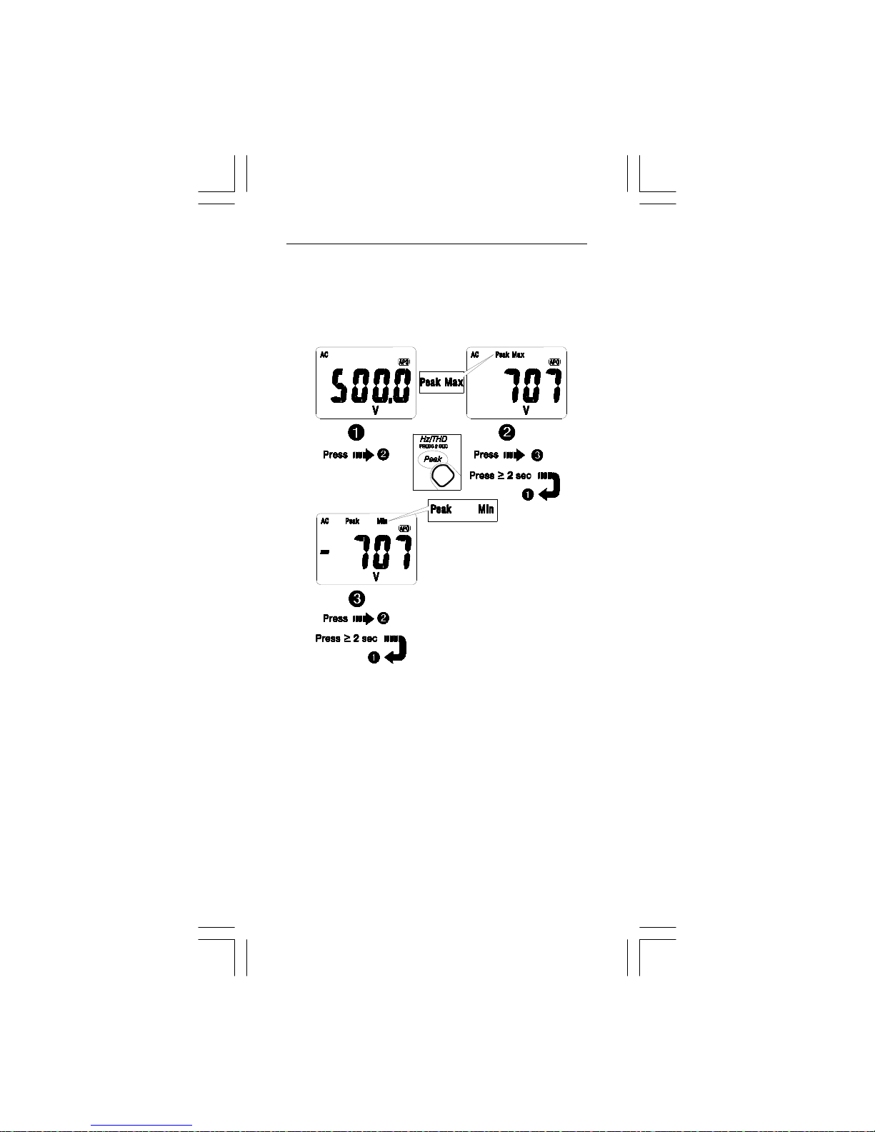
1-3-2 PEAK BUTTON (HZ/THD press for 2 sec):
- Auto AC, AC and AC+DC MODE are available for voltage
and current measurement.
a. PEAK HOLD
n Normal: Normal Operation.
o Peak Max : The instrument is activated to save the positive
peak value and the negative peak value. The posit ive pea k
value is displayed.
p Peak Min : The instrument is activated to save the positive
peak value and negative peak value. The negative peak
value is displayed.
NOTE: Press the HOLD button in PEAK HOLD mode to stop
the instrument updating the positive and negative peak values. When the HOLD mode is nested in PEAK HOLD mode,
the HOLD mode must be released before the PEAK HOLD
mode.
Overrange display :
OL: Peak Max value > 1400V or > 850 A
-OL: Peak Min value < -1400V or < -850 A
Page 9
EN-9
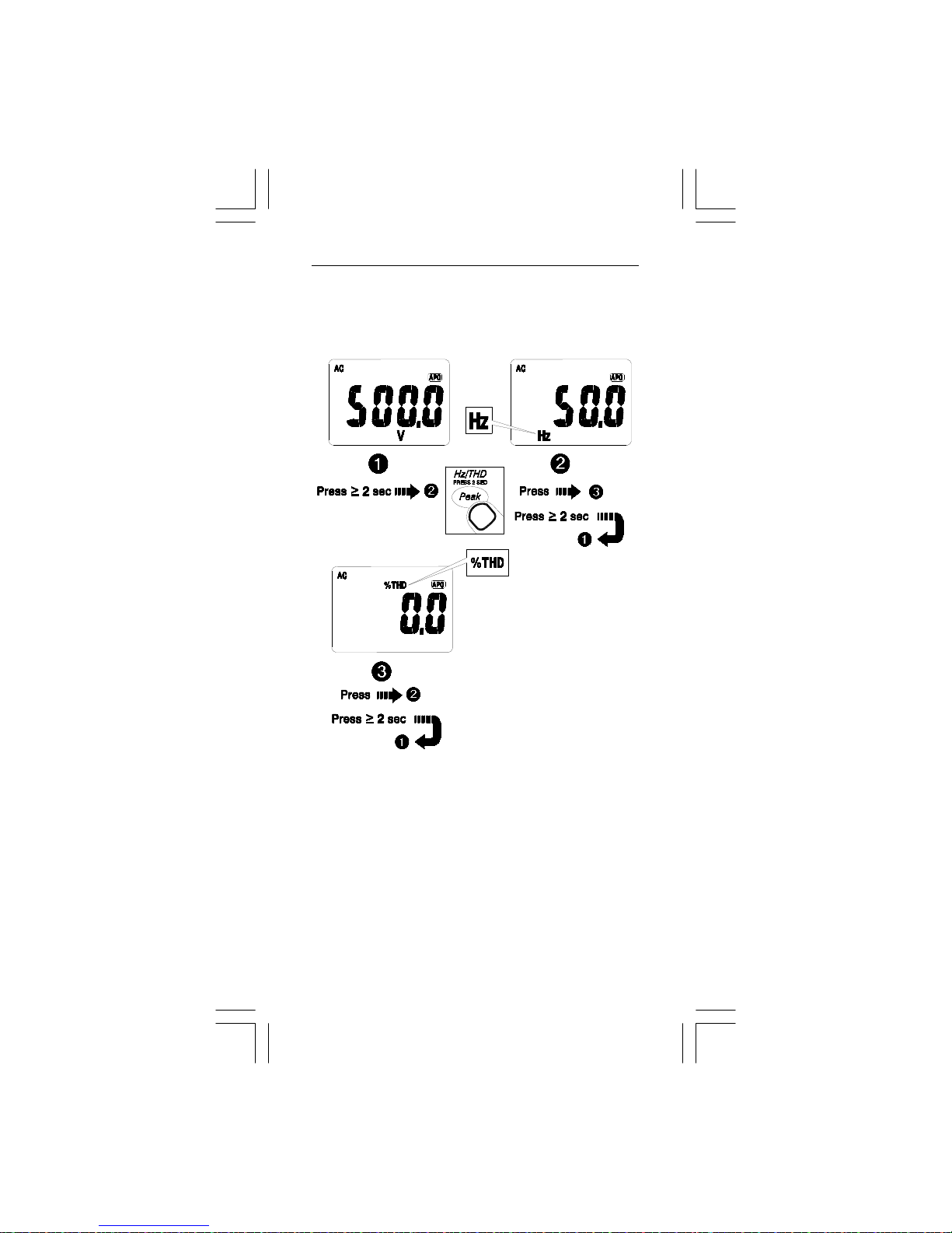
b. HZ/THD (=THD-R) Measurement:
- THD-R= RMS of Harmonics ÷ Total RMS of fundamental
and Harmonics ×100% (Harmonics up to 25th.)
Overrange display:
OL.U : Voltage overload (Vrms > 1000V)
OL.A : Current overload (Arms > 620A)
Page 10
EN-10
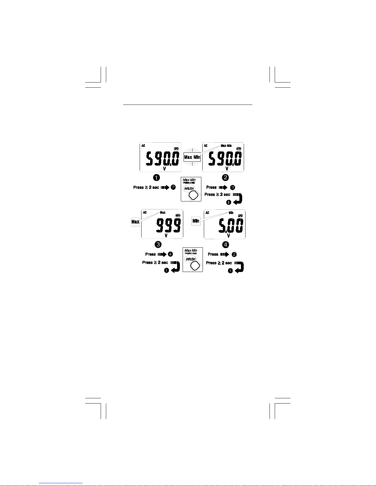
1-3-3 INRUSH BUTTON (Max Min press for 2 sec):
a. MAX MIN MODE:
- MAX MIN MODE is available for all functions.
n Normal : Normal Operation.
o MAX MIN (flashing) : The instrument is activated to save
the maximum and minimum value. The present value is
displayed.
p MAX : The instrument is activated to save the maximum
and minimum value. The maximum value is displayed.
q MIN : The instrument is activated to save the maximum
and minimum value. The minimum value is displayed.
NOTE :
- Press the HOLD button in MAX MIN mode to stop the
instrument updating the maximum and minimum values.
When the HOLD mode is nested in MAX MIN mode, the
HOLD mode must be released before the MAX MIN mode.
- Auto Power Off is disabled in MAX MIN mode.
Page 11
EN-11
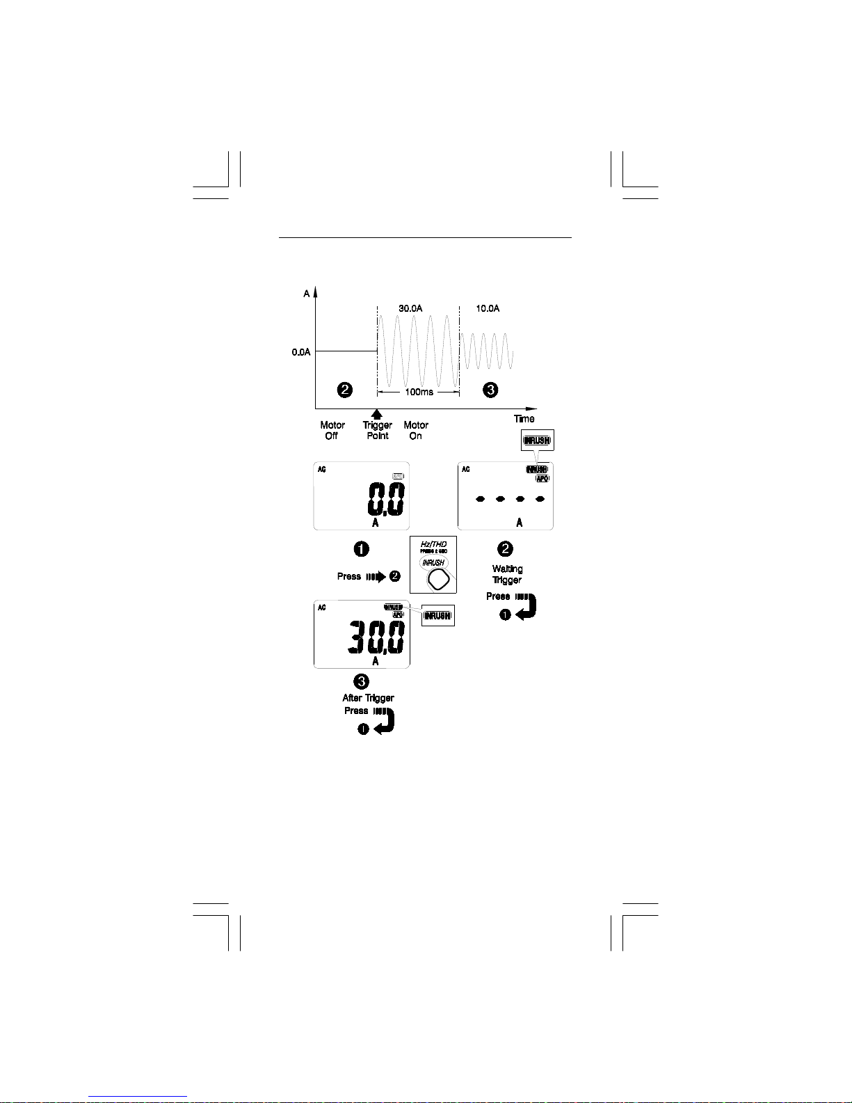
b. INRUSH CURRENT : ACA ONLY
Page 12
EN-12
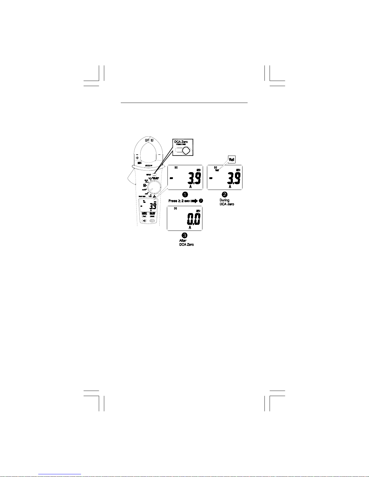
1-3-4 DCA ZERO: Remove the Jaws out of the conductor.
Press the HOLD BUTTON >2 sec to compensate the
residual magnetism.
0
A
- Auto DC, DC, and AC+DC MODE are available for current
measurement.
Page 13
EN-13
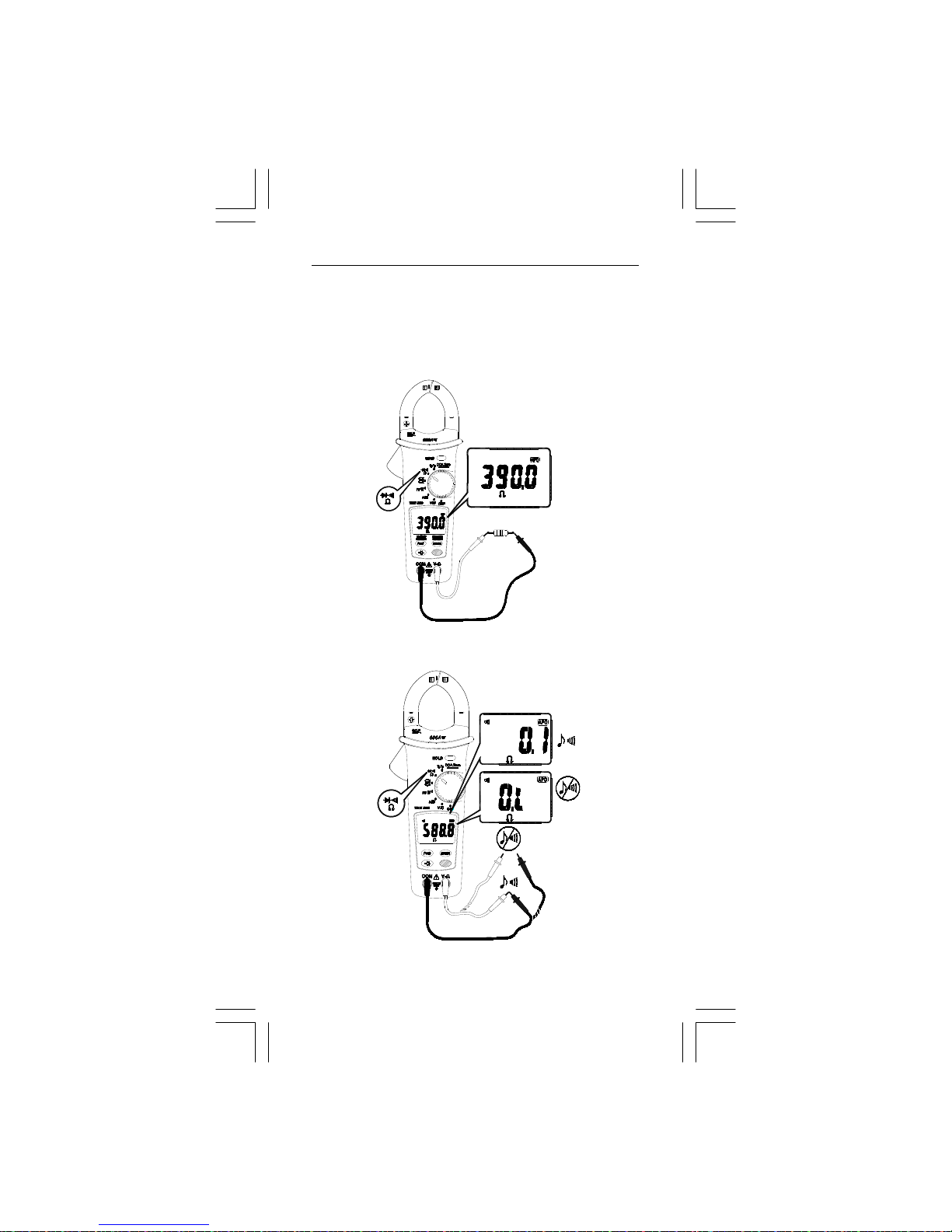
2. Resistance Measurement
Press the blue button to choose Resistance measurement,
Continuity check or Diode test mode.
Resistance measurement
Continuity check
Page 14
EN-14
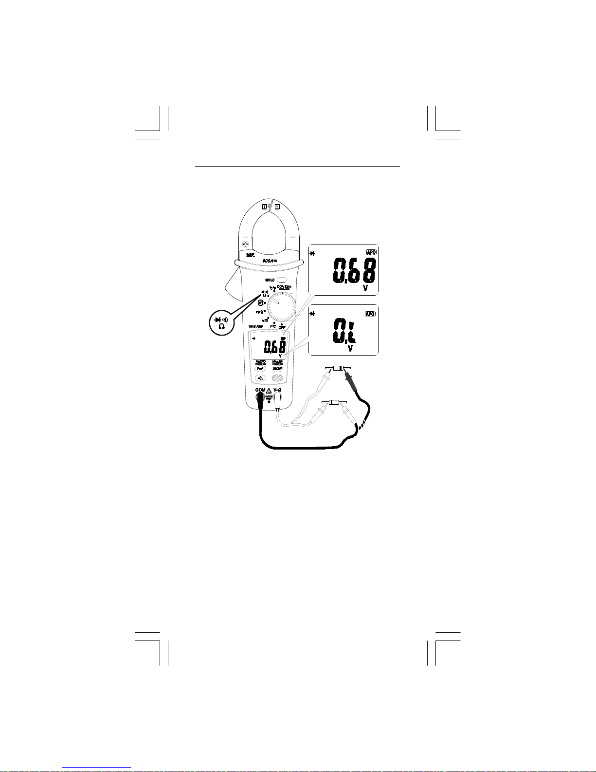
Diode testing
Page 15
EN-15
3. Active power (W)/Power factor (PF) Measurement
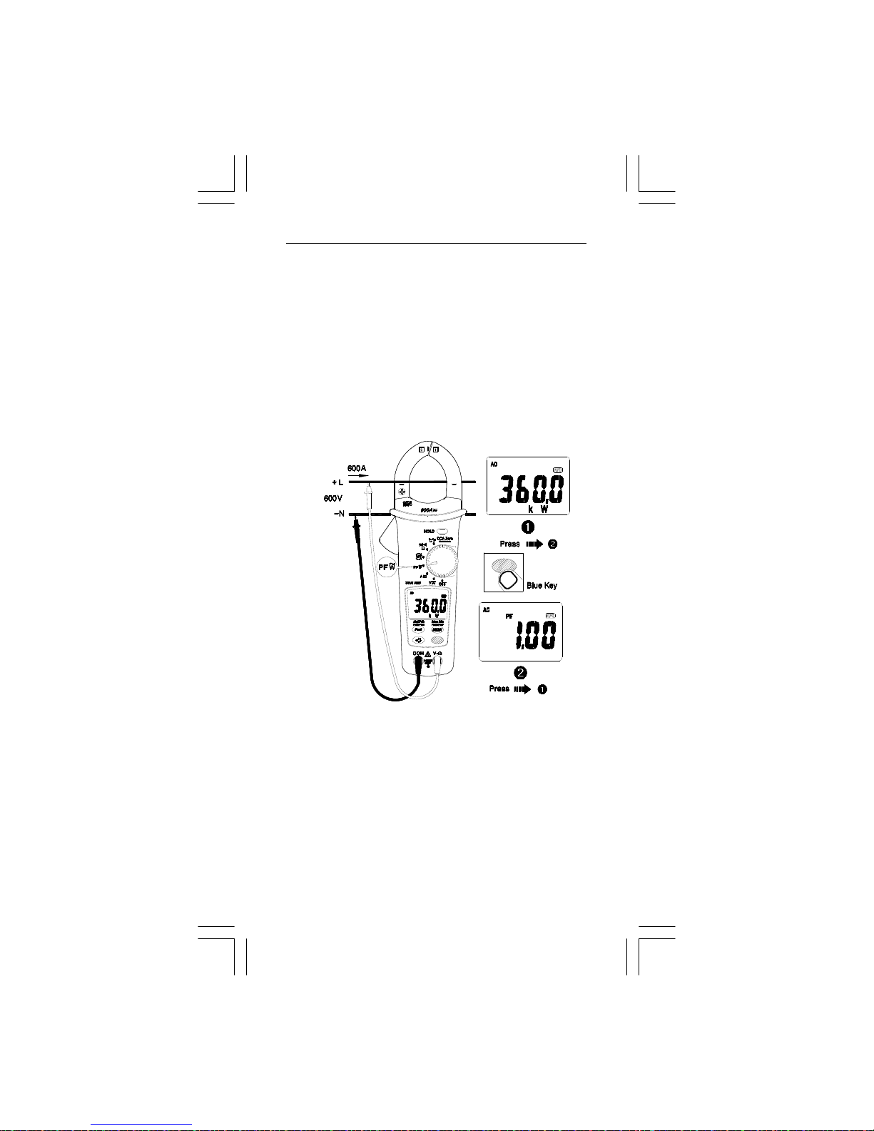
3-1 Single Phase Power Measurement
1. Plug the Black test lead into the COM terminal and the
Red test lead into the V-Ω terminal.
2. Set the rotary switch to the PF W~ posit ion.
3. Connect the Red test lead to the L, and the Black test lead
to the N.
4. Press the trigger to open the tran sfor mer jaws and clamp
around one conductor only. Ensure the jaw is firmly closed
around the conductor.
5. PRESS the BLUE button to choose between Active Power
(W) or POWER FACTOR (PF).
NOTE : For correct indication, the “ + ” symbol on the jaw
must face the power source side.
Active power polarity indication: Refer to above figure.
No sign: Indicates the power flows from the power source to
the load.
"_" sign: Indicates the power flows from the load to the
power source.
Power factor polarity indication:
No sign : The phase of the current signal is lagging
behind the voltage signal (inductive load).
"_" sign : The phase of the current signal is leading the
voltage signal (capacitive load).
Page 16
EN-16
Underrange display :
0.000 kW : Vrms <0.5V or Arms <0.5A
PF - - - - : Vrms <0.5V or Arms <0.5A
Overrange display:
OL.U : Voltage overload ( Vrms > 1000V)
OL.A : Current overload (Arms > 620A)
OL.UA : Both Voltage and current overload.
±OL kW : Active Power > 60 0 kW or < -6 00 kW.
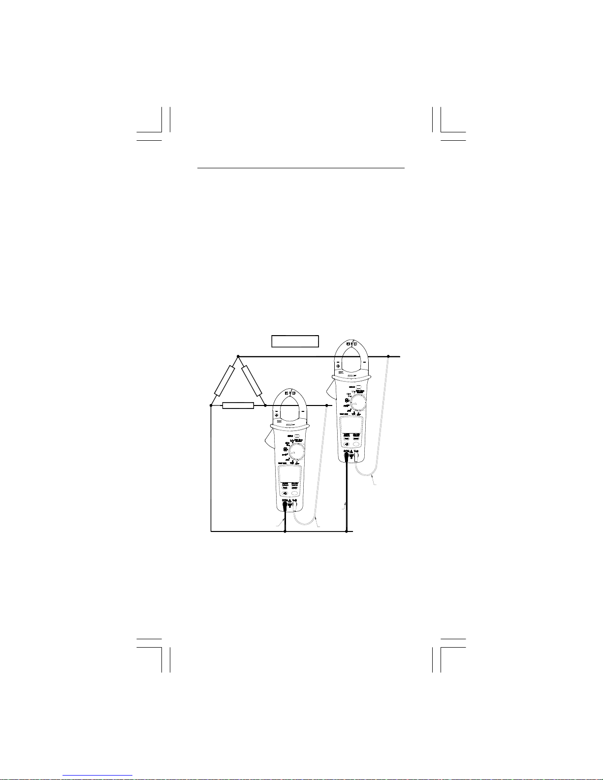
3-2 Three Phase Power Measurement
a. 3-phase 3 wire balanced / unbalanced
Set the rotary switch to the PF W~ position.
W1
W2
Red
Red
Black
1
2
3
Wye or star
Black
W=W1+W2
Page 17
EN-17
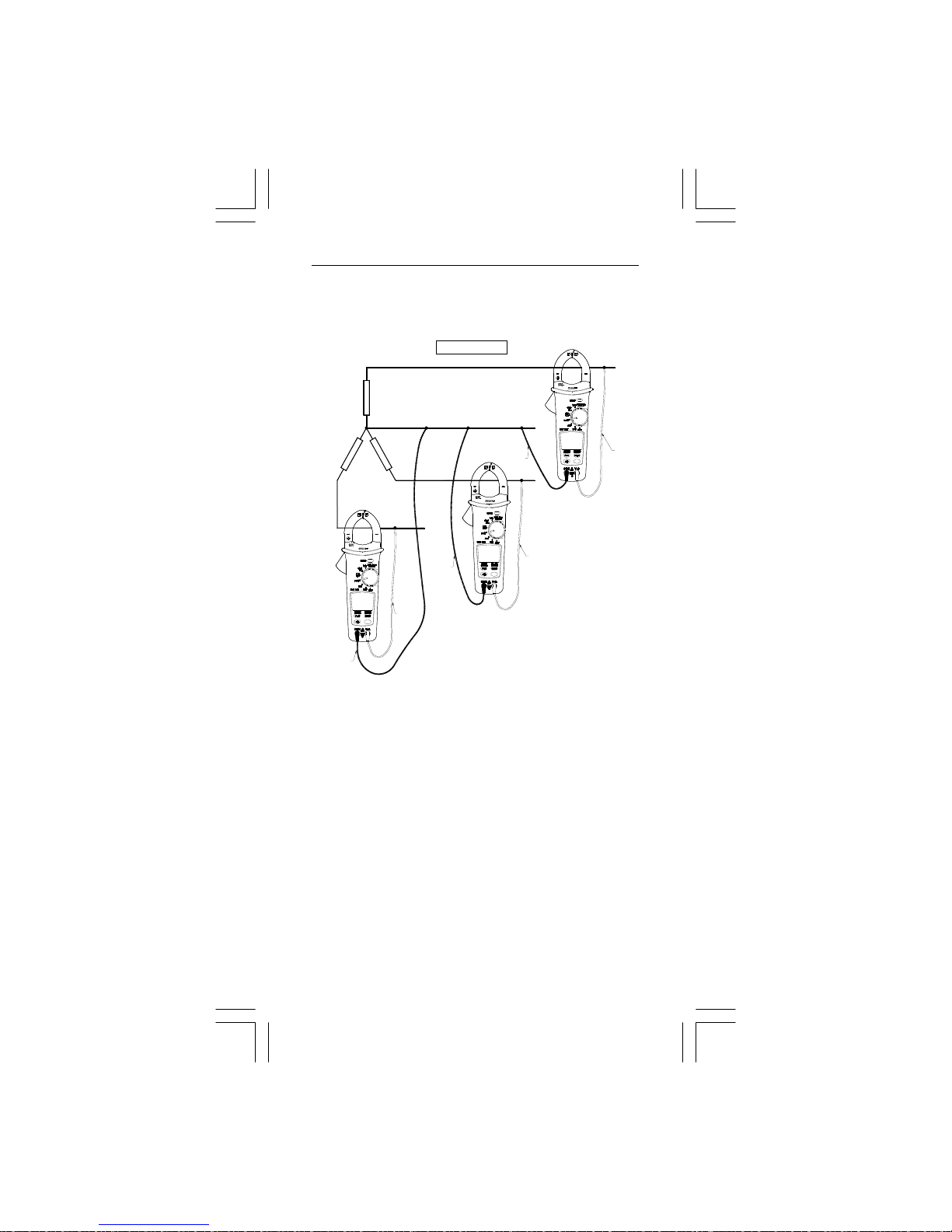
b. 3- phase 4 wire balanced / unbalanced
Set the rotary switch to the PF W~ position
W=W1+W2+W3
Black
Black
Black
Red
Red
Red
W3
W2
N
3
2
1
W1
Page 18
EN-18
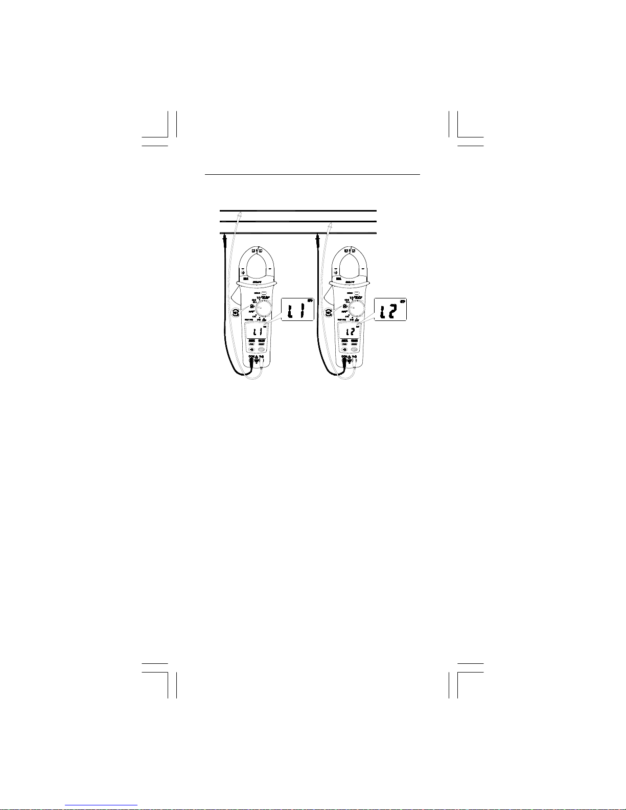
4. Phase Rotation
Line1
Line2
Line3
NOTE :
- Connect the three phases of the power source as shown
above.
- The test is only possible while the system frequency is
stable.
1. Plug the Black test lead into the COM terminal and the Red
test lead into the V-Ω terminal.
2. Set the rotary switch to the “ RST ” po sitio n.
3. Connec t th e Re d te st l ea d to the supposed phase 1, an d th e
Black test le a d to th e supposed phase 3.
a. If the voltage < 30V, it display will show “Lo V” ; if voltage
> 1000V, then it will show “OL V”.
b. If the frequency is not 50 Hz or 60 Hz, then it will display
“out. F ”.
c. If the voltage and frequency are normal, the display will
show “L1” for about 3 sec.
4. If the display shows “L2”, the BUZZER will sound twice.
Connect th e Re d t e st l ea d to t he supposed phase 2 be f ore
the “L2” has disappeared.
5. When “L2” has disappeared, the display will show the testing
result.
Page 19
EN-19
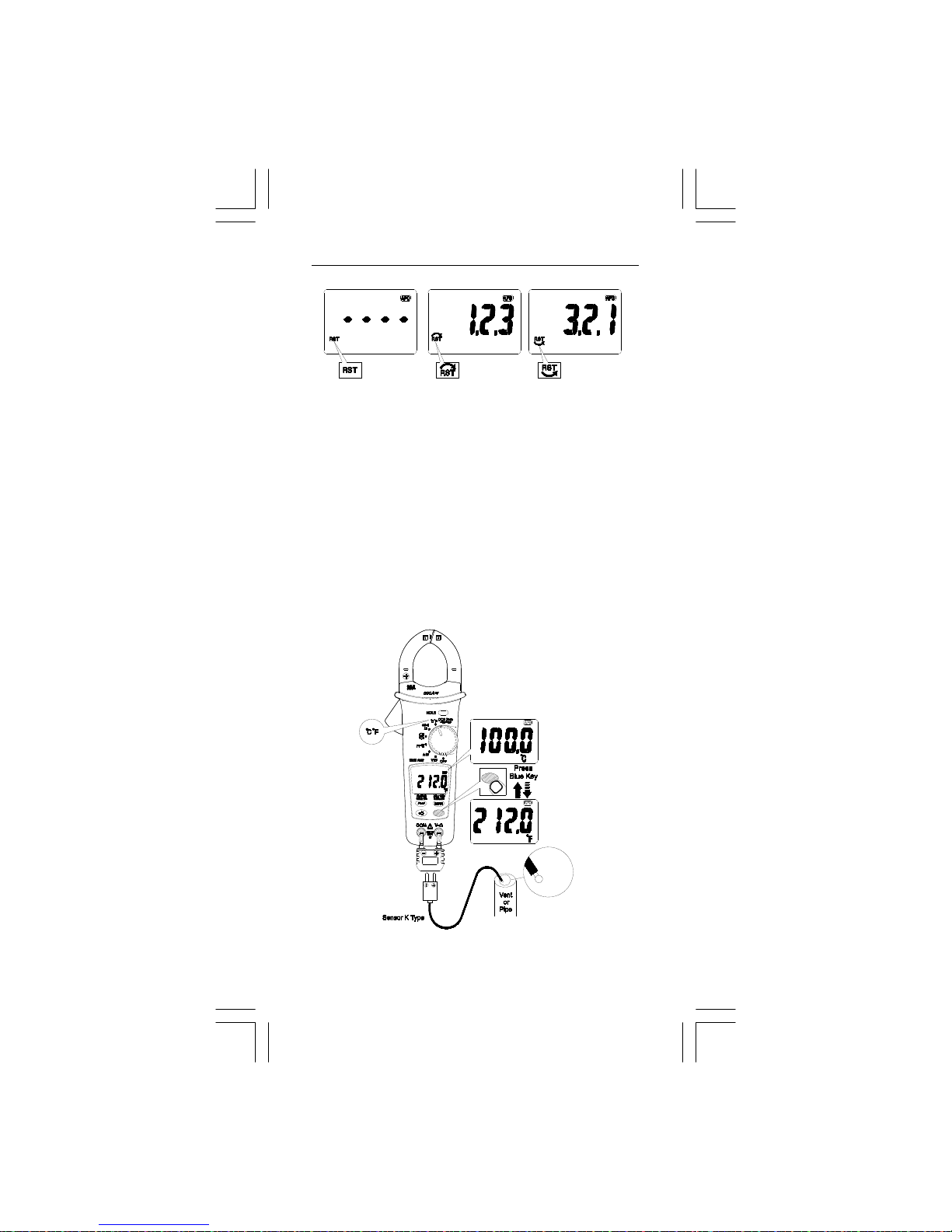
a. If it displays " 1.2.3 ", then the phase sequence is a forward
sequence, which means th e supposed phase 1 is ahe a d of
the supposed phase 2.
b. If it displays " 3.2.1 ", then the phase sequence is reversed
sequence, which means th e supposed phase 2 is ahe a d of
the supposed phase 1.
c. If the display shows "----" means it is unable to judge.
d. If the display shows "Lo V", it is possible the test leads
were removed before the instrument could determine the
correct sequence. Repeat the test.
6. Press Blue button to repeat the test.
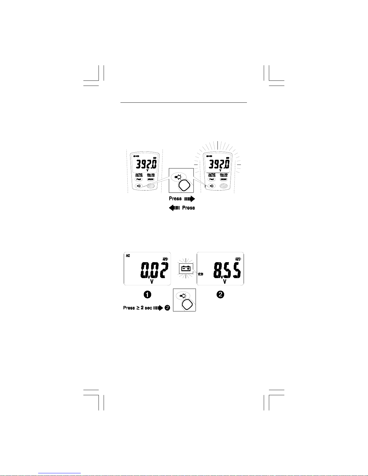
5. °C/°F Measurement
Page 20
EN-20
6. OTHER BUTTON FUNCTION
6-1 YELLOW BUTTON
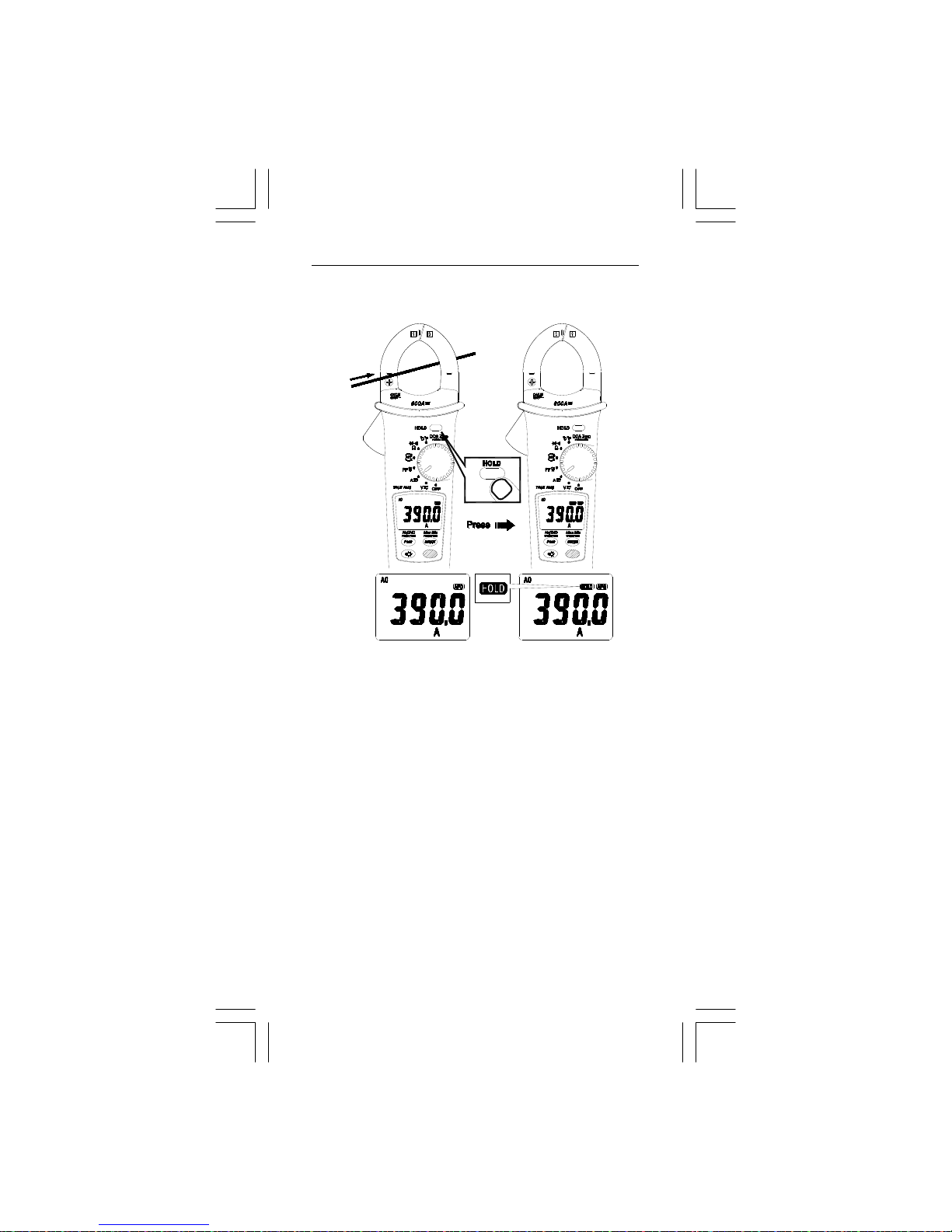
6-1-1 DISPLAY BACKLIGHT
Press the yellow LIGHT BUTTON, to turn the backlight on.
Press the button again to turn the backlight off otherwise the
backlight will automatically turn off after approx. 30 sec.
6-1-2 BATTERY VOLTAGE CHECK
Press the yellow LIGHT BUTTON > 2 sec and the display
will show the internal Battery Voltage. The minimum useable
battery voltage is 7.00V. Replace the battery when the
voltage is 7.00V or less.
Page 21
EN-21
6-2 HOLD BUTTON
0
A
3
9
0
A
Press the HOLD BUTTON to freeze the displayed value. Press
it again to unfreeze the display and return to normal operation.
7. Buzzer
The Instrument beeps once for every valid button-press, and
beeps twice for every invalid button-press.
8. Power-up options
Press the following button s wh ile turn ing t he in str umen t on to
enable the following functions:
PEAK BUTTON : disable auto power off.
INRUSH BUTTON : display of the software version.
HOLD BUTTON : display all LCD sy mbo ls appr ox 10 sec.
Page 22
EN-22
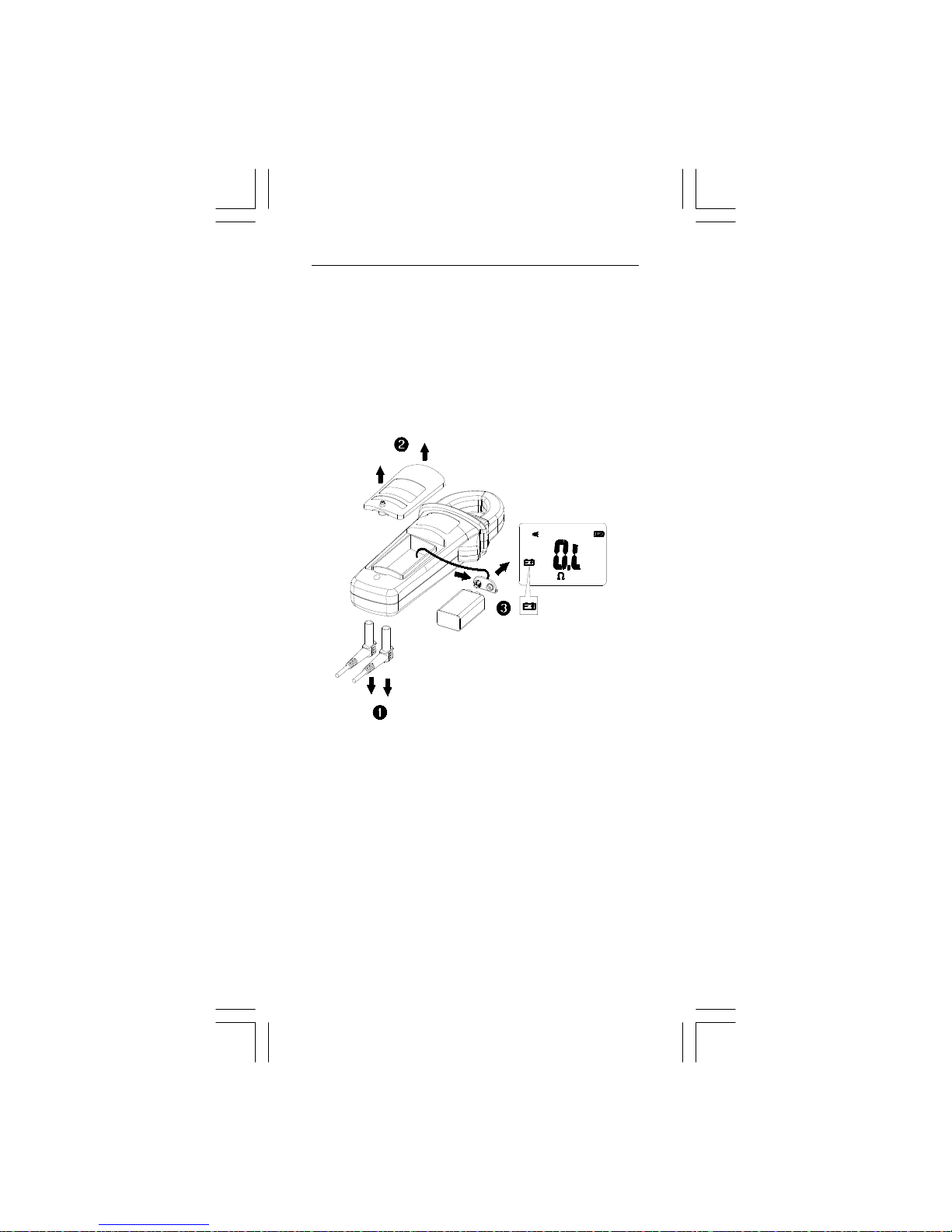
Battery Replacement
When the low battery indicator "" appears on the LCD,
replace the battery with the type given in the specifications.
WARNING
Disconnect the test leads from the circuit and the instrument
before removing the battery cover.
Refer to the following figure to replace the battery :
Page 23

EN-23
Specifications
1-1 General Specifications
LCD display digits : 3 5/6 digit large scale LCD readout.
Display count : 6000 counts.
Measuring rate : 3 times / sec.
Overrange display : "OL" or "-OL" .
Automatic power off time : Approximately 10 minutes after
power on.
Low battery indicator : is shown in the display. Replace
the battery when the indi ca tor appears.
Minimum battery voltage 7.00V
Power requirement :
9V battery Type 6LR61, IEC6LF22 or equivalent)
Battery life: Approxim at e ly 5 0 ho ur s w ith an A l ka line ba ttery.
1-2 Environmental Conditions
Indoor use only.
0°C to 30°C (32°F to 86°F) @ ≦80% RH
30°C to 40°C (86°F to 104°F) @ ≦75% RH)
40°C to 50°C (104°F to 122°F) @ ≦45%RH
Storage temperature :
-10 to +50°C (14°F to 122°F) @ 0 to 80% RH with batteries
removed from the instrument.
Measurement Category (Installation Category) :
per IEC 61010-1:2001: CAT.Ⅲ 600 V Pollut ion Degre e 2
Measurement Category l is for measurements performed on
circuits not directly connected to mains. Examples include:
Measurements on battery powered equipment and specially
protected (internal) mains-derived circuits.
Measurement Category ll is for measurements on circuits
directly connected to the low voltage installation. Examples
include: Household appliances, portable tools and similar
equipment.
Measurement Category lll is for measur e ment s pe rf or me d in
the building installation. Examples include measurements on
distribution boards, junction boxes, socket-outlets and wiring
and cables in the fixed installation.
Measurement Category lV is for measurements performed at
the source of the low-voltage installation. Examples include
measurements on primary overcurren t prot ect ion devices and
electricity meters.
Operating altitude: 2000m (6562 ft)
Conductor Size: Maximum 35mm diameter.
EMC: EN 61326-1
Page 24
EN-24
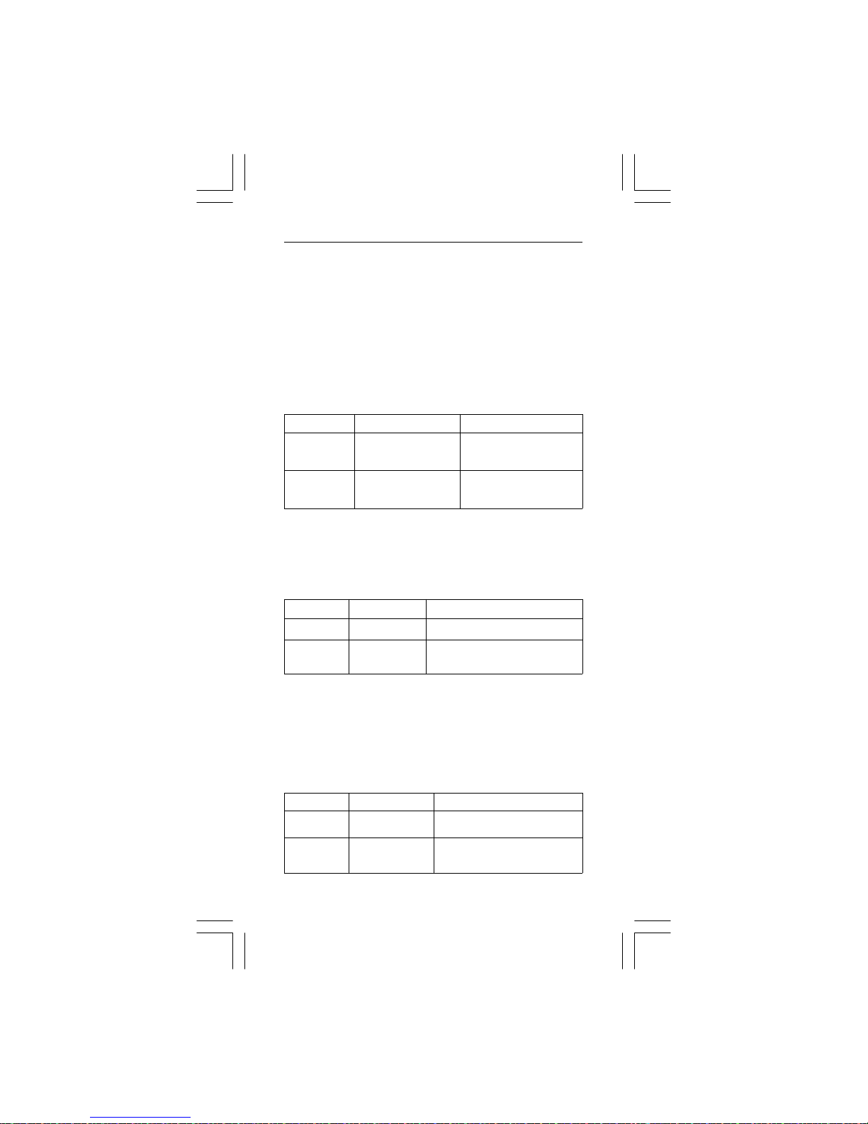
Function Range Accuracy
DCV
60.00V
600.0V
1000V
±(0.7%+ 5 dgt)
ACV
60.00V
600.0V
1000V
±(1.0% + 5 dgt)
45 Hz ~ 500 Hz
Overload protection : 1000Vrms
Input impedance : 3MΩ // less100pF
AC Conversion Type : AC/DC Coupled True RMS responding
AC+DC Vrms accuracy :
same as ACV spec. +1% rdg. + 5dgt.
Current
Function Range Accuracy
DCA 600.0A
±(1.5%+ 5 dgt )
ACA 600.0A
±(1.5% + 5 dgt ) 45 Hz ~ 65 H z
±(2.5% + 5 dgt ) 66 Hz ~ 400 Hz
Overload protection : 600Arms
Position Error : ±1% of reading.
AC Conversion Type : AC/DC Coupled True RMS responding
AC+DC Arms accuracy :
same as ACA spec. +1.5% rdg. +5dgt.
- DCA affected by the temperature and the residual
magnetism. Press HOLD button >2sec to compensate.
Peak Hold : Peak Max / Peak Min
Function Range Accuracy
ACV
85.0V
1400V
±(3% + 15 dgt)
ACA
85.0A
850A
±(3% + 15 dgt)
(corrected DCA Zero)
Shock and vibration: Sinusoidal vibration per MIL-T-28800E
(5 ~ 55 Hz, 3g maximum).
Drop Protection: 4 feet drop onto hardwood or concrete
floor.
1-3 Electrical Specifications
Accuracy is ±(% reading + number of digits) at 23°C ± 5°C
< 80%RH.
Temperature coefficient :
0.2 x (Specified accuracy) / °C, < 18°C, > 28°C .
Voltage
Page 25

EN-25
Overload protection : 1000Vrms/600Arms
Accuracy defined for :
Sine wave, ACV>5Vrms / ACA≧5Arms, Freq.50~400Hz.
- Only suitable for repetitive signals.
Frequency : Hz
Range Accuracy
20.0 ~ 399.9 Hz
400 ~ 4000 Hz
±(0.1% + 5 dgt)
Overload protection : 1000Vrms/600Arms
Sensitivity :
5Vrms for ACV, 5Arms for ACA ( >400Hz Unspecified)
- The reading will be 0.0 for signals below 10.0 Hz.
Function Range Accuracy
ACV / ACA
100.0%
±(3% + 10 dgt)
Overload protection : 1000Vrms/600Arms
- If ACV<10Vrms or ACA <10Arms, it will display “rdy”.
- If the fundamental frequency is out of range 45 ~ 65Hz, the
display will show “out.F”.
Inrush Current :
Function Range Accuracy
ACA
10.0 ~59.9A
60.0 ~ 600.0A
2.5% ± 2A
2.5% ± 5d
Overload protection : 600Arms
Accuracy defined for :
Sine wave, ACA≧10Arms, Freq. 50/60Hz
- Integration time about 100m sec
Active Power : Watts
Function Range Accuracy
W~
4.000 kW
40.00 kW
400.0 kW
600 kW
Add the errors of Voltage
and current.
Overload protection : 1000Vrms/600Arms
Accuracy defined for :
Sine wave, ACV≧10Vrms, ACA≧5Arms
Freq. 45~65Hz, PF=1.00
Page 26
EN-26
- The reading of Active Power may fluctuate due to small
changes in current when measured using the 4.000 kW
range.
Power Factor: PF = Watt ÷ (V×A)
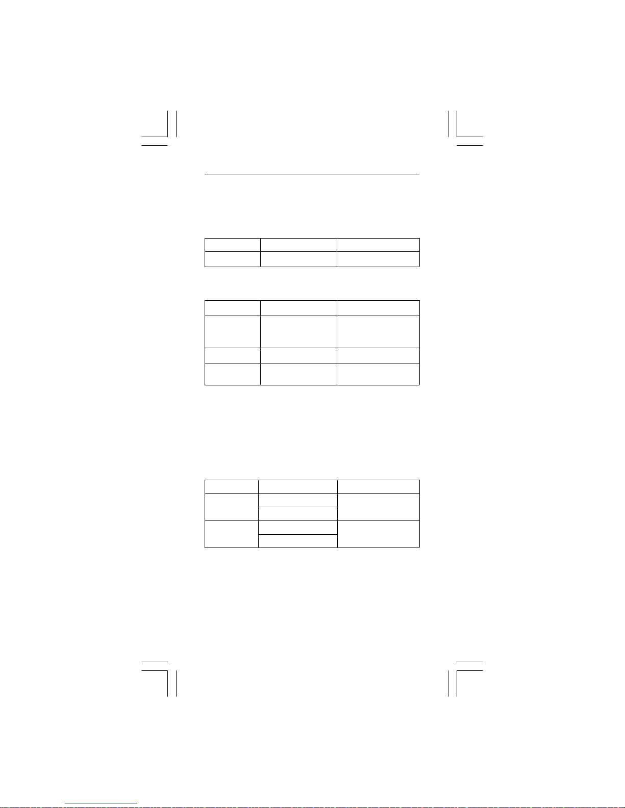
Function Range Accuracy
PF
-1.00 ~ 0.00 ~1.00
±3°
Overload protection : 1000Vrms/600Arms
Resistance, Continuity & Diode testing
Function Range Accuracy
Resistance
600.0 Ω
6.000 kΩ
20.00 kΩ
±(1%+ 5 dgt)
Diode
2.00V
±(1.5% + 5dgt)
for 0.4V ~ 0.8V
Continuity
600.0 Ω
±(1%+ 5 dgt)
Overload protection : 600Vrms
Max. Open Circuit voltage for Diode : 3.0V
Max. Open Circuit voltage for Ω ,;: 2.4V
Continuity check :
The internal buzzer activates if the resistance of the circuit
under test is less than 30Ω approximately.
Max. display count : 5400 counts.
Temperature
Function Range Accuracy
°C
-50.0 °C ~ 399.9°C
± (1% + 3°C )
400 °C ~ 1000 °C
°F
-58. 0 ° F ~ 751.9 °F
752 ° F ~ 1832 °F
±(1% + 6°F)
Overload protection : 600Vrms
- The above specification is assumed for an ambient
temperature stability of within ±1°C. The instrument requires
a 1 hour stabilization period for ambient temperature
changes of more than ±1°C.
Page 27

EN-27
Limited Warranty
This instrument is warranted to the original purchaser against
defects in material and workmanship for 3 years from the date
of purchase. During this warranty period, RS Components will,
at its option, replace or repair the defective unit, subject to
verification of the defect or malfunction. This warranty does not
cover disposable batteries, fuses or damage from abuse,
neglect, accident, unauthorized repair, alteration, contamination, or abnormal conditions of operation or handling.
Any implied warranties arising out of the sale of this product,
including but not limited to implied warranties of merchantability
and fitness for a particular purpose, are limited to the above.
RS Components shall not be liable for loss of use of the
instrument or other incidental or consequential damages,
expenses, or economic loss, or for any claim or claims for such
damage, expense or economic loss. Some states or countries
laws vary, so the above limitations or exclusions may not apply
to you. For full terms and conditions, refer to the current RS
Catalogue.
Page 28

Asia
Iso-Tech
460 Alexandra Road, #15-01A
PSA Building
Singapore 119963
USA
7410 Pebble Drive
Fort Worth
Texas 76118-6961
Europe
Iso-Tech
PO Box 99
Corby
Northamptonshire
NN17 9RS
United Kingdom
Canada
1701 Woodward Drive
Ste 108 Ottawa
Ontario K2C 0R4, Canada
Japan
West Tower (12th Floor)
Yokohama Business Park
134 Godocho, Hodogaya
Yokohama,
Kanagawa 240-0005 Japan
South America
Av. Pdte. Eduardo Frei M. 6001-71
Centro Empresas El Cortijo
Conchali, Santiago, Chile
 Loading...