

Page 1
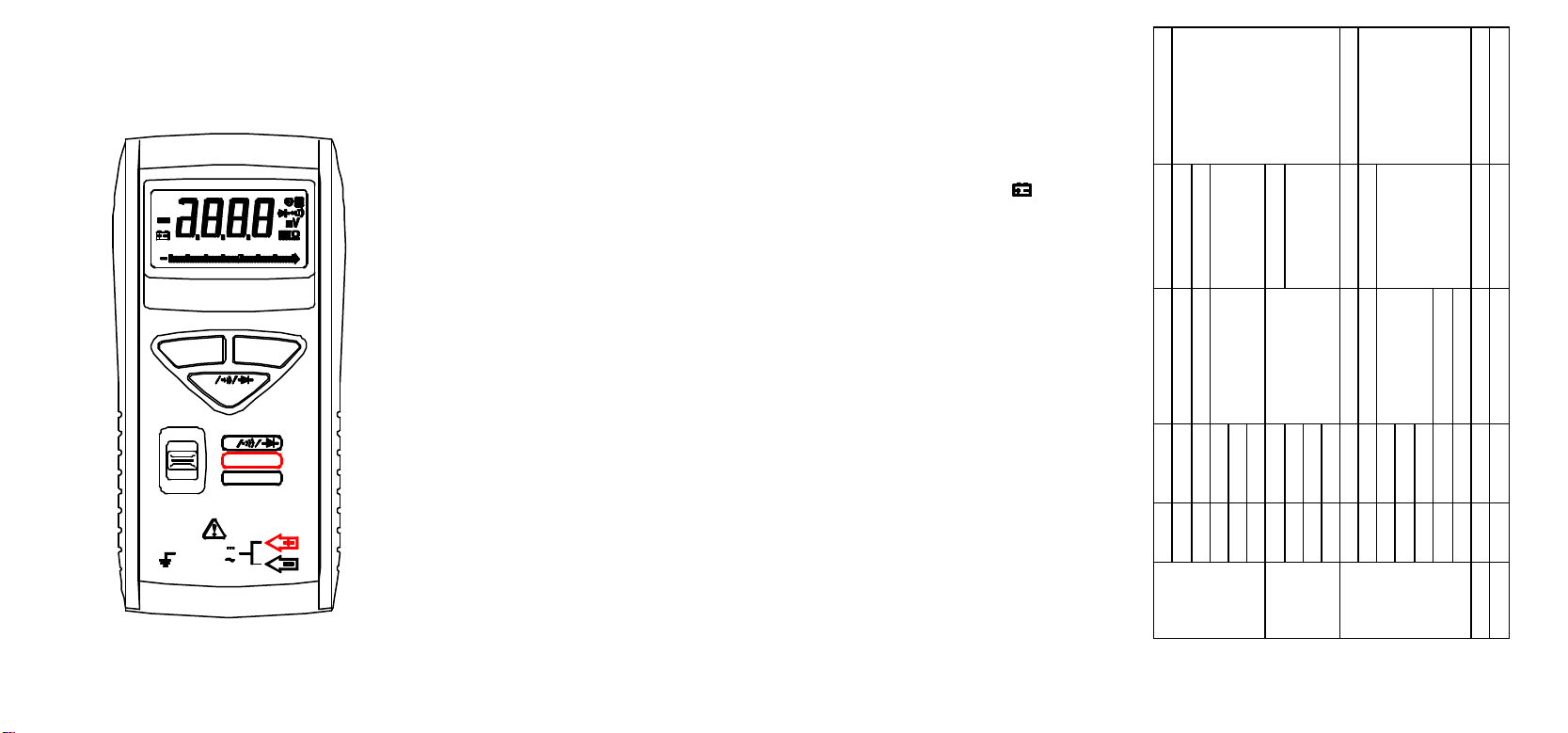
OPERATING INSTRUCTIONS
Overload Protection
Ω
Open circuit volts
Accuracy
10mV
100mV 1V Resolution
Ω
34V 340V 600V Range
Ω
POCKET
DIGITAL MULTIMETER
DC
AC
0 2010 30
RANGE HOLD
Ω
DC/AC
Ω
VOLT
OFF
AUTO POWER OFF
600V
MAX
600V
CATIII 300V CATII 600V
SAFETY INFORMATION
The following safety information must be observed
to insure maximum personal safety during the
operation at this meter:
Do not use the meter if the meter or test leads look
damaged, or if you suspect that the meter is not
operating properly.
Never ground yourself when taking electrical
measurements. Do not touch exposed metal pipes,
outlets, fixtures, etc., which might be at ground
potential. Keep your body isolated from ground by
using dry clothing, rubber shoes, rubber mats, or
any approved insulating material.
Turn off power to the circuit under test before
cutting, unsoldering, or breaking the circuit. Small
amounts of current can be dangerous.
Use caution when working above 60V dc or 30V ac
rms. Such voltages pose a shock hazard.
When using the probes, keep your fingers behind
the finger guards on the probes.
Measuring voltage which exceeds the limits of the
multimeter may damage the meter and expose the
operator to a shock hazard. Always recognize the
meter voltage limits as stated on the front of the
meter.
SPECIFICATIONS
Display: 3½digit liquid crystal display (LCD) with
a maximum reading of 3400, with a 34-segment
analog bar-graph.
Polarity: Automatic, (-) negative polarity
indication.
Overrange: "OL" mark indication.
Low battery indication: The " " is displayed
when the battery voltage drops below the operating
level.
Measurement rate: 2 times per second, nominal.
Bar graph: 20 times per second.
Auto power off: approx. 8 minutes.
Operating environment: 0°C to 40°C (32°F to
144°F) at <70% R.H.
Storage temperature: -20°C to 60°C (-4°F to
140°F) at < 80% R.H. with battery removed from
meter.
Temperature Coefficient: 0.1 x (specified accuracy)
per °C. (0°C to 18°C, 28°C to 40°C).
Power: Two 1.5 button-type batteries (IEC # LR-44,
NEDA # 1166A).
Battery life: 70 hours continuous operation.
Dimensions: 125mm (H) x 60mm (W) x 24mm
(D).
Weight: Approx. 3.9 oz. (110g) including batteries
and case.
(Accuracy at 23°C ± 5°C, <70% R.H.)
Overload Protection
100MΩ
Input Impedance
ACCURACY
± 2.0% rdg + 2 dgts
100µV
Resolution
Range
340mV
10M
± 1.0% rdg + 2 dgts
1mV
3.4V
600V DC or AC rms
10MΩ
9.1MΩ
± 2.0% rdg + 2 dgts
10mV
100mV
34V
340V
DCV
9.1MΩ
± 4.0% rdg + 5 dgts
1V
1mV
3.4V
600V
ACV
(50/60Hz)
-1.2Vdc
± 2.0% rdg + 5 dgts
100m
340
450V DC or AC rms
± 2.0% rdg + 4 dgts
1Ω
10Ω
3.4kΩ
34kΩ
OHM
450V DC or AC rms
450V DC or AC rms
-0.45Vdc
Test current 1.0mA
Response time: 500ms
± 3.0% rdg + 4 dgts
± 5.0% rdg + 5 dgts
± 3.0% rdg + 3 dgts
Audible indication: < 35Ω
1kΩ
1mV
100Ω
10kΩ
100mΩ
2V
340kΩ
340Ω
34MΩ
3.4MΩ
Diode Test
Continuity
Page 2

OPERATION
Before attempting to replace the battery,
first disconnect the Test Leads from any
Before taking any measurements, read the Safety
Information Section. Always examine the
instrument for damage, contamination (excessive
dirt, grease, etc.) and defects. Examine the test leads
for cracked or frayed insulation. If any abnormal
conditions exist do not attempt to make any
measurements.
Autoranging
The meter defaults to autorange when you turn it on. In
autorange, the meter selects the range automatically.
Manually Selecting a Range
The meter also has a manual range mode. In manual range,
you select and lock the meter in a range. To manually
select a range:
Press [RANGE] button to hold the selected range.
Subsequently pressing the [RANGE] button will select
each range in sequence from the lowest to highest range.
Hold the button for 2 seconds to return to the Autorange
Mode.
Data Hold Feature
Press [HOLD] button to toggle in and out of the Data Hold
mode. In the data hold mode, the " H" annunciator is
displayed and the last reading is held on the display.
Press [HOLD] button again to release the hold and current
readings are once again displayed.
Mode Switch (DC/AC), (Ω / / )
Press this switch to toggle between DC and AC in the
voltage measurements. Press this switch to toggle between
the continuity/diode and ohms modes, if the function
switch is set to Ω / / position.
Measuring Voltage
1. Set the Function Switch to " VOLT" position.
2. Press Mode switch to toggle between "DC" and "AC".
The "DC" to "AC" mark is displayed.
3. Touch the probes to the test points. The range will
change automatically to the level that will display the
input voltage with best resolution.
4. The value indicated in the display window is the
measured value of voltage with proper decimal point and
annunciator indication.
Measuring Resistance and Testing Continuity
1. Set the function switch to Ω / / position.
2. Turn off power to the circuit under test. External voltage
across the components causes invalid readings.
3. To toggle between the ohms/continuity/diode modes,
press Mode Switch.
4. Touch the probes to the test points. In ohms, the value
indicated in the display is the measured value of
resistance with proper decimal point and annunciator
indication. In continuity test, the beeper sounds
continuously, if the resistance is less than approximately
35Ω.
Testing Diodes
1. Set the Function switch to Ω / / position.
2. Turn off power to the circuit under test. External voltage
across the components causes invalid readings.
3. Press Mode Switch to toggle between the
ohms/continuity/diode modes
4. Touch probes to the diode. A forward -voltage drop is
about 0.6V (typical for a silicon diode).
5. Reverse probes. If the diode is good, "OL" is displayed.
If the diode is shorted, a value near 0mV will be
displayed.
6. If the diode is open, "OL" is displayed in both
directions.
7. Audible Indication: Less than 0.25V.
Auto Power off
1. Auto power off: approx. 8 minutes.
2. After auto power off, press any button to restart the
meter, and the reading of measurement will be
maintained in the display.
Cancellation Of Auto Power Off Feature: Press and hold
the (RANGE) button while rotating function switch
from off to any position to turn the meter on. The
auto power off feature is disabled.
Safety: Conforms to IEC1010-1 (EN61010-1), Rev-2;
CATII 600V, CATIII 300V.
EMC: Conforms to EN61326.
The symbols used on this instrument are:
Caution, refer to accompanying documents
Equipment protected throughout by Double
insulation (Class II)
Alternating current
Direct current
Ground
BATTERY REPLACEMENT
Power is supplied by two button-type batteries (NEDA
1166A, IEC LR -44). The " " appears on the LCD
display when replacement is needed.
WARNING
energized circuit.
1. Disconnect the test leads from any energized circuit.
2. Set the Function Switch to OFF.
3. Remove battery cover screw.
4. Slide off battery cover and change batteries.
5. Replace battery cover and screw.
SCREW
 Loading...