

Page 1
Iris Technology Corporation [CAGE 78535]
PO Box 5838, Irvine, CA 92616-5838
949.975.8410 tel / 949.975.8498 fax
Toll free 866.240.9540 / www.iristechnology.com
QuietPower 1800 (QP-1800)
DC to AC Power Inverter
TM 11460A-OR/1 A
APRIL 2010
PCN 500 114600 00
Operator’s Manual
Operator’s Manual
Document 287.F701 / 100412 / Rev 12 APR 2010
Supersedes Document 287.F701 / 070901 / Rev 01 SEP 07
Page 2

Iris Technology Operator's Manual
QuietPower 1800 (QP-1800) Doc 287.F701 / 100412
Notice of Copyright
Iris Technology QuietPower Inverter (QP-1800) Owner‟s Manual.
© APR 2010 Iris Technology Corporation. All rights reserved.
Disclaimer
Unless specifically agreed to in writing, Iris Technology Corporation (Iris):
(a) makes no warranty as to the accuracy, sufficiency, or suitability of any
technical or other information provided in its manuals or other documentation.
(b) assumes no responsibility or liability for loss or damage, whether direct,
indirect, consequential, or incidental, which might arise out of the use of such
information. The use of such information will be entirely at the user‟s risk.
Document Number
TM 11460A-OR/1 A / PCN 500 114600 00
287.F701 / 100412 / Rev 12 APR 2010
Supersedes Document 287.F701 / 070901 / Rev 01 SEP 07
U. S. Government Copyright Release
Iris Technology Corporation grants permission to the U.S. Government to reprint
this technical manual for use as needed. This permission includes but is not
limited to posting on U.S. Government websites. This document is subject to
periodic revision and the user is encouraged to check the Iris Technology
website (www.iristechnology.com) for the most current version of this document.
Trademarks
Any references to copyrighted or trademarked names referred to in this document
are the properties of their respective owners.
Page 2 of 56 Rev 12 APR 2010
Page 3

Iris Technology Operator's Manual
QuietPower 1800 (QP-1800) Doc 287.F701 / 100412
TABLE OF CONTENTS
TABLE OF CONTENTS ......................................................................................................................................... 3
APPENDICES ..................................................................................................................................................... 5
LIST OF FIGURES ............................................................................................................................................... 5
LIST OF TABLES ................................................................................................................................................. 5
SYMBOLS AND CONVENTIONS ............................................................................................................................ 6
SPECIFIC WARNINGS AND HAZARDS OF THIS DEVICE .......................................................................................... 7
GENERAL SAFETY PRECAUTIONS ..................................................................................................................... 10
EXPLOSIVE GAS PRECAUTIONS ........................................................................................................................ 11
PRECAUTIONS WHEN WORKING WITH BATTERIES............................................................................................. 11
FCC INFORMATION .......................................................................................................................................... 12
DEPARTMENT OF DEFENSE PRODUCT EVALUATION .......................................................................................... 12
SECTION 1
INTRODUCTION
1.1 INTRODUCTION ................................................................................................................................................ 13
1.2 EQUIPMENT IDENTIFICATION AND DESCRIPTION ................................................................................................. 14
1.3 INVERTER KEY FEATURES ................................................................................................................................. 16
1.3.1 INVERTER FUNCTION ........................................................................................................................................ 16
1.3.2 CONTROL PANEL .............................................................................................................................................. 16
SECTION 2
INSTALLATION
2.1 GENERAL ......................................................................................................................................................... 18
2.2 REQUIREMENTS FOR INSTALLATION .................................................................................................................. 18
2.3 INSTALLING THE INVERTER ............................................................................................................................... 18
2.4 LOCATING THE INVERTER ................................................................................................................................. 19
2.5 MOUNTING THE INVERTER ................................................................................................................................ 21
2.5.1 CONTROL PANEL ORIENTATION ......................................................................................................................... 22
2.6 WIRING THE INVERTER ..................................................................................................................................... 22
2.6.1 MAKING DC WIRING CONNECTIONS .................................................................................................................... 22
2.6.2 DC GROUNDING (ON-VEHICLE) .......................................................................................................................... 24
2.6.3 DC GROUNDING (OFF-VEHICLE) ......................................................................................................................... 24
SECTION 3
OPERATION
3.1 GENERAL ......................................................................................................................................................... 25
3.2 PRINCIPLES OF OPERATION .............................................................................................................................. 25
3.3 OUTPUT WAVEFORM ......................................................................................................................................... 25
3.4 CONTROL PANEL .............................................................................................................................................. 26
3.4.1 TO OPERATE THE QUIETPOWER INVERTER: ........................................................................................................ 27
3.5 POWERSAVE MODE .......................................................................................................................................... 27
3.6 INVERTER OPERATING LIMITS AND PROTECTION FEATURES ................................................................................ 28
3.7 PERFORMANCE GRAPHS AND SPECIFICATIONS .................................................................................................. 30
3.7.1 POWER DERATING CURVE ................................................................................................................................. 30
3.7.2 EFFICIENCY CURVE .......................................................................................................................................... 31
3.7.3 TECHNICAL SPECIFICATIONS ............................................................................................................................. 32
3.8 USAGE GUIDELINES FOR THE QP-1800 .............................................................................................................. 33
Page 3 of 56 Rev 12 APR 2010
Page 4

Iris Technology Operator's Manual
QuietPower 1800 (QP-1800) Doc 287.F701 / 100412
SECTION 4
TEST AND TROUBLESHOOTING
4.1 GENERAL ......................................................................................................................................................... 34
4.2 TESTING .......................................................................................................................................................... 34
4.3 TROUBLESHOOTING ......................................................................................................................................... 35
4.3.1 FAULT CONDITIONS AND INDICATORS ................................................................................................................ 35
4.3.2 TROUBLESHOOTING TIPS .................................................................................................................................. 36
SECTION 5
PREVENTATIVE MAINTENANCE
5.1 GENERAL ......................................................................................................................................................... 37
5.2 INSPECT AND CLEAN ........................................................................................................................................ 37
5.2.1 INSPECTION ..................................................................................................................................................... 37
5.2.2 CLEANING ........................................................................................................................................................ 38
5.3 NATO CABLE REPLACEMENT ............................................................................................................................. 39
5.3.1 NATO CABLE REMOVAL ..................................................................................................................................... 39
5.3.2 NATO CABLE INSTALLATION .............................................................................................................................. 40
5.4 STORAGE ........................................................................................................................................................ 41
5.5 PREPARATION FOR SHIPMENT ........................................................................................................................... 41
SECTION 6
CORRECTIVE MAINTENANCE
6.1 GENERAL ......................................................................................................................................................... 42
6.2 INSPECT AND CLEAN ........................................................................................................................................ 42
6.2.1 INSPECTION ..................................................................................................................................................... 42
6.2.2 CLEANING ........................................................................................................................................................ 43
6.3 FUSE REPLACEMENT ........................................................................................................................................ 44
6.3.1 FUSE REMOVAL ................................................................................................................................................ 44
6.3.2 FUSE INSTALLATION ......................................................................................................................................... 45
SECTION 7
WARRANTY AND SERVICE
7.1 GENERAL ......................................................................................................................................................... 46
7.2 WARRANTY ...................................................................................................................................................... 46
7.3 WARRANTY SERVICE ........................................................................................................................................ 47
Page 4 of 56 Rev 12 APR 2010
Page 5

Iris Technology Operator's Manual
QuietPower 1800 (QP-1800) Doc 287.F701 / 100412
APPENDIX A
VEHICLE CONSIDERATIONS
A.1 VEHICLE ALTERNATOR ...................................................................................................................................... 48
A.2 MILITARY BATTERIES ........................................................................................................................................ 48
A.3 LOAD AND RUNTIME.......................................................................................................................................... 50
APPENDIX B
TECHNICAL ADDENDUM
B.1 QP-1800 PERFORMANCE WITH VEHICLE AND ENVIRONMENTAL FACTORS ............................................................ 51
B.1.1 TEMPERATURE EFFECTS ON BATTERY PERFORMANCE ....................................................................................... 51
B.1.2 AGE AND CONDITION OF THE VEHICLE BATTERY ................................................................................................. 52
B.1.3 CONDITION AND INTEGRITY OF THE VEHICLE CABLING ........................................................................................ 52
B.1.4 LOOSE CONNECTIONS ...................................................................................................................................... 52
B.2 OPERATION WITH SURGE SUPPRESSION POWER STRIPS ..................................................................................... 52
B.3 OPERATION WITH DOWNSTREAM EMC COMPONENTS .......................................................................................... 52
B.4 FREQUENTY ASKED QUESTIONS (FAQS). ............................................................................................................ 53
LIST OF FIGURES
FIGURE 1: FRONT PANEL OF THE QP-1800 ........................................................................................................ 17
FIGURE 2: REAR PANEL OF THE QP-1800 .......................................................................................................... 17
FIGURE 3: APPROVED MOUNTING ORIENTATIONS OF THE QP-1800 ..................................................................... 21
FIGURE 4: CONTROL PANEL ROTATION AND ATTACHMENT .................................................................................. 22
FIGURE 5: INVERTER NATO CABLE .................................................................................................................... 22
FIGURE 6: VEHICLE GROUNDING REQUIREMENTS FOR THE QP-1800 ................................................................... 24
FIGURE 7: QUIETPOWER INVERTER TRUE SINE WAVE OUTPUT ............................................................................ 25
FIGURE 8: QP-1800 CONTROL PANEL ................................................................................................................ 26
FIGURE 9: OUTPUT POWER (W) DERATING CURVE .............................................................................................. 30
FIGURE 10: EFFICIENCY (%) AND HEAT DISSIPATION (W) .................................................................................... 31
FIGURE 11: INVERTER COVER REMOVAL ........................................................................................................... 45
FIGURE 12: FUSE REMOVAL AND REPLACEMENT. ............................................................................................... 45
FIGURE 13: RUNTIME HOURS VS AMPS OVER TEMPERATURE .............................................................................. 51
FIGURE 14: ENERGY FLOW ............................................................................................................................... 54
LIST OF TABLES
TABLE 1: QUIETPOWER SYSTEM AND COMPONENT PARTS LIST ........................................................................... 14
TABLE 2: OPERATING LIMITATIONS .................................................................................................................... 28
TABLE 3: SYSTEM TRIP VOLTAGES .................................................................................................................... 28
TABLE 4: TECHNICAL SPECIFICATIONS ............................................................................................................... 32
TABLE 5: FAULT CONDITIONS AND INDICATORS .................................................................................................. 35
TABLE 6: TROUBLESHOOTING TIPS .................................................................................................................... 36
TABLE 7: INSPECTION (EXTERNAL) .................................................................................................................... 37
TABLE 8: CLEANING (EXTERNAL) ....................................................................................................................... 38
TABLE 9: INSPECTION (INTERNAL) ..................................................................................................................... 42
TABLE 10: CLEANING (INTERNAL) ...................................................................................................................... 43
TABLE 11: COMPARISON OF MILITARY BATTERY SPECIFICAITONS ........................................................................ 49
TABLE 12: SAMPLE LOAD AND RUNTIME TABLE .................................................................................................. 50
Page 5 of 56 Rev 12 APR 2010
Page 6

Iris Technology Operator's Manual
- NOTE -
Provides useful additional information for the user.
CAUTION
The hazard may result in minor or moderate damage to equipment and
may render it inoperative.
WARNING
A POTENTIALLY HAZARDOUS SITUATION WHICH, IF NOT AVOIDED, COULD
RESULT IN DEATH OR SERIOUS INJURY.
QuietPower 1800 (QP-1800) Doc 287.F701 / 100412
Symbols and Conventions
The following conventions are used in this manual to communicate hazards to the operator, device or associated
equipment that may occur with improper installing, operating, maintaining and servicing this equipment. These
symbols are also used to make the operator aware of the inherent and potential hazards associated with this type of
equipment.
Page 6 of 56 Rev 12 APR 2010
Page 7
Iris Technology Operator's Manual
WARNING
FIRE AND SHOCK HAZARD. MAKE SURE THE CABLE IS
DISCONNECTED FROM 24 VDC POWER SOURCE PRIOR TO INSTALLING
CABLE ONTO INVERTER TERMINALS. FAILURE TO DISCONNECT
CABLE FROM 24 VDC POWER SOURCE (NATO PLUG) FIRST MAY
RESULT IN FIRE, SEVERE ELECTRIC SHOCK, OR DEATH.
WARNING
BEFORE MAKING CONNECTIONS, ROUTE THE POSITIVE AND
NEGATIVE BATTERY WIRES DIRECTLY TO THE DC CONNECTION
TERMINALS ON THE QUIETPOWER INVERTER FIRST.
WARNING
SHOCK HAZARD. MAKE SURE GROUND CONNECTIONS ARE
MAINTAINED BETWEEN THE INVERTER, VEHICLE, AND GROUND ROD
(IF APPLICABLE). FAILURE TO DO SO COULD RESULT IN A POTENTIAL
SHOCK HAZARD.
WARNING
DO NOT DISASSEMBLE THE QUIETPOWER INVERTER. ONLY
QUALIFIED ELECTRONICS MAINTENANCE TECHNICIANS ARE
PERMITTED TO REPLACE THE FUSE. ATTEMPTS TO SERVICE THE
INVERTER BY UNQUALIFIED PERSONNEL MAY RESULT IN A RISK OF
ELECTRIC SHOCK OR FIRE. REFER TO SECTION 7, WARRANTY AND
SERVICE, FOR INSTRUCTIONS ON SERVICING THE INVERTER.
QuietPower 1800 (QP-1800) Doc 287.F701 / 100412
Specific Warnings and Hazards of this Device
The following are specific warning, cautions and hazards related to the installation, use,
maintenance and service of this device.
Page 7 of 56 Rev 12 APR 2010
Page 8

Iris Technology Operator's Manual
WARNING
MAKE SURE INVERTER IS ELECTRICALLY DISCONNECTED FROM 24
VDC POWER SOURCE (NATO PLUG) PRIOR TO SERVICING. FAILURE
TO DISCONNECT INVERTER FROM 24 VDC POWER SOURCE (NATO
PLUG) FIRST MAY RESULT IN FIRE, SEVERE ELECTRIC SHOCK, OR
DEATH.
WARNING
DO NOT DISASSEMBLE THE QUIETPOWER INVERTER. ONLY
QUALIFIED ELECTRONICS MAINTENANCE TECHNICIANS ARE
PERMITTED TO REPLACE THE FUSE. ATTEMPTS TO SERVICE THE
INVERTER BY UNQUALIFIED PERSONNEL MAY RESULT IN A RISK OF
ELECTRIC SHOCK OR FIRE. REFER TO SECTION 7, WARRANTY AND
SERVICE, FOR INSTRUCTIONS ON SERVICING THE INVERTER.
CAUTION
Review the Important Safety Instructions found at the beginning of this
manual and read this entire section, paying particular attention to the
CAUTION and WARNING statements, before proceeding with the
installation.
CAUTION
It is recommended that you read the entire wiring instruction Section first
before attempting to wire the Inverter
CAUTION
Make sure cable is connected properly: positive (+), red wire to left post
and negative (-), black wire to right post. Connecting cable improperly
may result in internal damage to inverter.
QuietPower 1800 (QP-1800) Doc 287.F701 / 100412
Page 8 of 56 Rev 12 APR 2010
Page 9

Iris Technology Operator's Manual
CAUTION
Do not disassemble the QuietPower inverter. Only qualified electronics
maintenance technicians are permitted to replace the fuse. Attempts to
service the inverter by unqualified personnel may result in a risk of
electric shock or fire. Refer to section 7, warranty and service, for
instructions on servicing the inverter.
CAUTION
Do not use harsh or abrasive cleaners on the QuietPower inverter or
NATO cable. Do not use petroleum-based products of any kind. Damage
can result if these precautions are not followed. Use only a non-abrasive
cloth dampened with soap and water to clean inverter and NATO cable.
Do not attempt to flush the unit with liquids of any kind.
CAUTION
If you are installing the NATO Cable for the first time, install the red
terminal cover on the red lead and the black terminal cover on the black
lead.
QuietPower 1800 (QP-1800) Doc 287.F701 / 100412
Page 9 of 56 Rev 12 APR 2010
Page 10

Iris Technology Operator's Manual
QuietPower 1800 (QP-1800) Doc 287.F701 / 100412
General Safety Precautions
The following are general safety precautions that are not related to any specific procedures and
therefore do not appear elsewhere in this publication. These are recommended precautions
that personnel must understand and apply during many phases of operation and maintenance.
Keep away from live circuits. Operating personnel must at all times observe all safety
regulations. Do not replace components or make adjustments inside the equipment with
the voltage supply turned on. Under certain conditions, dangerous potentials may exist
when the power control is in the OFF position. To avoid casualties, always remove
power and discharge. Ground a circuit before touching it.
Do not service or adjust alone. Under no circumstances should any person reach into
or enter the enclosure for the purpose of servicing or adjusting the equipment except in
the presence of someone who is capable of rendering aid.
Resuscitation. Personnel working with or near high voltages should be familiar with
modern methods of resuscitation. Such information may be obtained from the Red
Cross (www.redcross.org).
Save these instructions. This Owner‟s Manual contains important safety and operating
information for the QuietPower Inverter.
The QuietPower Inverter has a Ground Fault Circuit Interrupter (GFCI) and a Circuit
Breaker for your safety. These features are critical to the safe operation of this system
and must not be disabled.
Do not expose the QuietPower Inverter to rain, snow, spray, bilge or dust. To
reduce risk of fire hazard, do not cover or obstruct the ventilation openings. Do not
install the QuietPower Inverter in a zero-clearance compartment. Overheating may
result.
Do not use attachments not recommended or sold by Iris Technology. Doing so
may result in a risk of fire, electric shock, or injury to persons.
The QuietPower Inverter is designed to connect to a military vehicle 24 VDC power
system through an available and/or supplied NATO Cable.
Do not operate the QuietPower Inverter with damaged wiring. To avoid a risk of fire
and electric shock, make sure that existing wiring is in good electrical condition.
Do not operate the QuietPower Inverter if it has received a sharp blow, been
dropped, or otherwise damaged in any way. If the QuietPower Inverter has been
damaged, refer to Section 7, Warranty and Service.
Do not disassemble the QuietPower Inverter. Only qualified electronics maintenance
technicians are permitted to replace the fuse. Attempts to service the inverter by
unqualified personnel may result in a risk of electric shock or fire. Refer to Section 7,
Warranty and Service, for instructions on servicing the inverter.
To reduce risk of electrical shock, disconnect the DC power from the QuietPower
Inverter before attempting any maintenance or cleaning or working on any
equipment and circuits connected to the QuietPower Inverter. Turning off controls
will not reduce this risk.
Page 10 of 56 Rev 12 APR 2010
Page 11

Iris Technology Operator's Manual
QuietPower 1800 (QP-1800) Doc 287.F701 / 100412
Explosive Gas Precautions
This equipment contains components which can produce arcs or sparks. To
prevent fire or explosion do not install in compartments containing batteries or flammable
materials or in locations which require ignition protected equipment. This includes any
space containing gasoline-powered machinery, fuel tanks, or joints, fittings, or other
connection between components of the fuel system.
Working in the vicinity of a lead-acid battery is dangerous. Batteries generate
explosive gasses during normal battery operation.
To reduce the risk of battery explosion, follow these instructions and those
published by the battery manufacturer and the manufacturer of the equipment in
which the battery is installed.
Precautions When Working With Batteries
Do not work alone. Someone should be within range of your voice or close enough to
come to your aid when you work near a lead-acid battery.
Have plenty of fresh water and soap nearby in case battery acid contacts skin,
clothing, or eyes.
Wear complete eye protection and clothing protection. Avoid touching eyes while
working near batteries.
Wear eye protection to keep corrosion from coming in contact with eyes, when
cleaning battery terminals and before making connections.
If battery acid contacts skin or clothing, wash immediately with soap and water. If
acid enters eye, immediately flood eye with running cold water for at least 20 minutes
and get medical attention immediately.
NEVER smoke or allow a spark or flame in vicinity of battery or engine.
Do not drop a metal tool on the battery, nor allow metal to contact the battery
terminals or vehicle chassis. The resulting spark or short-circuit on the battery or other
electrical part may cause an explosion.
Remove personal metal items such as rings, bracelets, necklaces, and watches
when working with a lead-acid battery. A lead-acid battery produces a short-circuit
current high enough to weld a ring or the like to metal, causing a severe burn.
Page 11 of 56 Rev 12 APR 2010
Page 12

Iris Technology Operator's Manual
QuietPower 1800 (QP-1800) Doc 287.F701 / 100412
FCC INFORMATION
This equipment has been tested and found to comply with the limits for a Class B digital device,
pursuant to Part 15 of the FCC Rules. These limits are designed to provide reasonable
protection against harmful interference in a residential installation. This equipment generates,
uses, and can radiate radio frequency energy and, if not installed and used in accordance with
the instructions, may cause harmful interference to radio communications. However, there is no
guarantee that the interference will not occur in a particular installation. If this equipment does
cause harmful interference to radio or television reception, which can be determined by turning
the equipment off and on, the user is encouraged to try to correct the interference by one or
more of the following measures:
Reorient or relocate the receiving antenna.
Increase the separation between the equipment and receiver.
Connect the equipment into an outlet on a circuit different from that to which the receiver
is connected.
Consult the dealer or an experienced radio/TV technician for help.
Department of Defense Product Evaluation
This equipment has been tested extensively by the Department of Defense (DoD) and is
approved and recommended for use in wheeled military vehicles. Contact Iris Technology for
details about obtaining a copy of these data (Restricted Distribution, FOUO).
Page 12 of 56 Rev 12 APR 2010
Page 13

Iris Technology Operator's Manual
QuietPower 1800 (QP-1800) Doc 287.F701 / 100412
Section 1
Introduction
1.1 Introduction
Thank you for your purchase of the QuietPower 1800 Inverter. As a high quality, true sine wave
output inverter, you can expect the QuietPower Inverter to deliver exceptional performance and
give you years of dependable operation. The true sine wave AC output from the QuietPower
Inverter ensures all AC loads operating from the unit perform efficiently and correctly. Since
these loads were designed to operate from true sine wave voltage, you can expect these loads
to operate the same as if operating from grid/utility supplied power. In some cases, the true
sine wave output from the QuietPower Inverter is superior to the power supplied by your utility
company.
To get the most out of your QuietPower Inverter, carefully read and follow the instructions in this
guide. Pay special attention to the Important Safety Instructions in this guide and to the
WARNING and CAUTION statements found throughout the guide and on the product. Please
retain all packaging.
Should you have any questions before, during, or after installation, please call Iris Technology's
Customer Service Department for help.
Customer Service (Toll Free): (866) 240-9540
Customer Service (Local): (949) 975-8410
Customer Service (Fax): (949) 975-8498
Customer Service (Email): support@iristechnology.com
Record the following information for use when contacting Iris for servicing of the unit.
QuietPower Serial #: ___________________________ (Required)
Date of purchase: ___________________________ (If Available)
Contract reference: ___________________________ (If Available)
Page 13 of 56 Rev 12 APR 2010
Page 14
Iris Technology Operator's Manual
Iris PN / NSN
Image
Description / Components
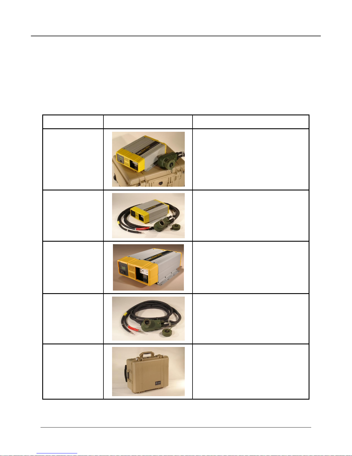
287A120
6130-01-552-6350
QP-1800 Inverter System
NATO Cable (12 ft)
Transportation Case
287A107
6130-01-496-6456
QP-1800 Inverter
NATO Cable (12 ft)
287A101
6130-01-496-6448
QP-1800 Inverter
287A106
6150-01-497-2515
NATO Cable (12 ft)
287A108
7050-01-551-0600
Transportation Case
Outside dimensions:
22.1” x 17.9” x 10.4”
(560 x 455 x 265 mm)
QuietPower 1800 (QP-1800) Doc 287.F701 / 100412
1.2 Equipment Identification and Description
Table 1 lists the QuietPower systems and components that can be ordered. The parts you
receive depend on the part number ordered. Three different systems can be ordered, as well as
individual components. All inverter options ship with an Operator‟s Manual and Installation Kit.
The current revision of the Operator‟s Manual is downloadable from www.iristechnology.com.
Table 1: QuietPower System and Component Parts List
Page 14 of 56 Rev 12 APR 2010
Page 15
Iris Technology Operator's Manual
Iris PN / NSN
Image
Description / Components
287F701
QP-1800 Operator‟s Manual
TM 11460A-OR/1 A
PCN 500 114600 00
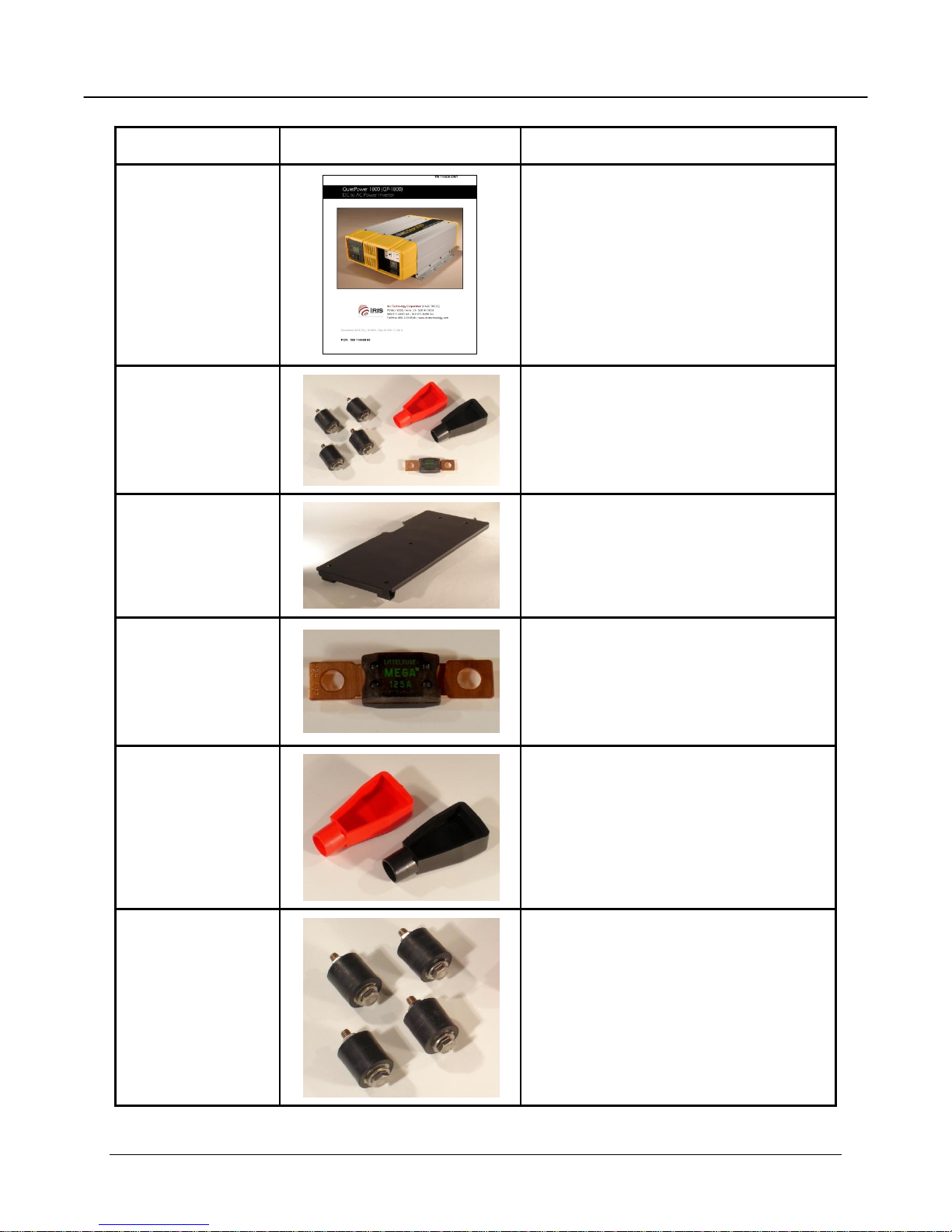
287A109
Installation Kit
Replacement Fuse (1)
Battery Terminal Covers (2)
Vibration Isolators (4)
287A125
Vehicle Mounting Plate
for use with HMMWV
2870128 (EA)
5920-01-562-3354
Replacement Fuse
Littlefuse Mega 125 (125 A)
PN / MEG 125 (EA)
Fuse replacement requires a
Qualified Electronics Technician
2870140 (SET)
2870136 (BK)
2870137 (RD)
Battery Terminal Cover (SET)
Straight Clamp, 3/0 AWG
BK (Negative) PN / 4271 (EA)
RD (Positive) PN / 4272 (EA)
2870140 (SET)
2870110 (EA)
Vibration Isolators (SET)
Neoprene Cylindrical Mount
M/F, 1/4"-20, 1" Ht, 1" Wd
QuietPower 1800 (QP-1800) Doc 287.F701 / 100412
Page 15 of 56 Rev 12 APR 2010
Page 16

Iris Technology Operator's Manual
QuietPower 1800 (QP-1800) Doc 287.F701 / 100412
1.3 Inverter Key Features
The QuietPower Inverter utilizes advanced high frequency switching technology in the power
conversion process. The circuits are similar to those used in power supplies for computers and
other electronic equipment. This technology offers several benefits:
Light weight: for easy installation
Pure sine wave output: for reduced interference
High surge capability: for „hard-to-start” AC loads
High frequency switching: for nearly silent operation
Refer to paragraph 3.7, Performance Graphs and Specifications, for complete specifications.
1.3.1 Inverter Function
When connected properly and the power switch is turned to the „I‟ (On) position, the QuietPower
Inverter draws power from the 24 VDC (nominal) battery and/or vehicle electrical bus and
delivers a true sine wave 115 VAC (nominal @ 15 A) output. As long as the input voltage is
maintained within the operating range of the unit, the QuietPower will continue to deliver AC
power to the loads connected. High and low battery shutdowns will engage if the battery
voltage falls out of the specified range of operation (20-32 VDC).
1.3.2 Control Panel
The Control Panel provides Off/On („O/I‟) control and displays operating information so you can
monitor the status of the Inverter and your batteries.
This panel can be removed and re-attached in different orientations so the display information is
directed at you in the most convenient fashion for all recommended mounting configurations.
The procedure to rotate the panel is found in section 2.5.
Page 16 of 56 Rev 12 APR 2010
Page 17
Iris Technology Operator's Manual
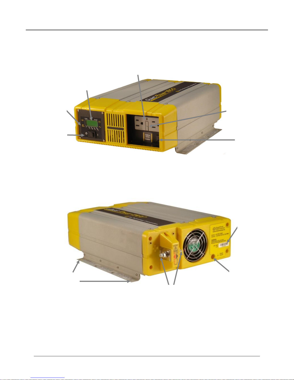
Circuit
Breaker
GFCI
(Ground Fault
Circuit Interrupter)
Off/On
(O/I)
Control
Panel
LCD
Display
Duplex (AC)
Outlet
Serial
Number
Ground
Lug
Isolators (4)
(Not Shown)
Input
Terminals (2)
QuietPower 1800 (QP-1800) Doc 287.F701 / 100412
Figure 1: Front Panel of the QP-1800
Page 17 of 56 Rev 12 APR 2010
Figure 2: Rear Panel of the QP-1800
Page 18

Iris Technology Operator's Manual
CAUTION
Review the Important Safety Instructions found at the beginning of this
manual and read this entire section, paying particular attention to the
CAUTION and WARNING statements, before proceeding with the
installation.
QuietPower 1800 (QP-1800) Doc 287.F701 / 100412
Section 2
Installation
2.1 General
This section contains instructions for installing the QuietPower Inverter. After installing the unit
and making wiring connections, DO NOT turn the unit on. Proceed to Section 3, Operation,
which provides operating instructions.
2.2 Requirements for Installation
You will need the following tools and hardware to properly install the QuietPower Inverter:
Wrench for DC terminals (½” or 13 mm)
Wrench for Vibration Isolators (optional, 7/16”)
2.3 Installing the Inverter
Install the inverter as follows:
1. Find a suitable location to install the QuietPower Inverter. Refer to paragraph 2.4,
Locating the Inverter, for more information.
2. Install the inverter. Refer to paragraph 2.5, Mounting the Inverter, for more
information.
Page 18 of 56 Rev 12 APR 2010
Page 19

Iris Technology Operator's Manual
WARNING
FIRE AND SHOCK HAZARD. MAKE SURE THE CABLE IS
DISCONNECTED FROM 24 VDC POWER SOURCE PRIOR TO INSTALLING
CABLE ONTO INVERTER TERMINALS. FAILURE TO DISCONNECT
CABLE FROM 24 VDC POWER SOURCE (NATO PLUG) FIRST MAY
RESULT IN FIRE, SEVERE ELECTRIC SHOCK, OR DEATH.
CAUTION
Make sure cable is connected properly: positive (+), red wire to left post
and negative (-), black wire to right post. Connecting cable improperly
may result in internal damage to inverter.
QuietPower 1800 (QP-1800) Doc 287.F701 / 100412
3. Install the NATO Cable to the inverter first and then to the 24 VDC power source.
Refer to paragraph 2.6, Wiring the Inverter, for more information.
4. Before turning the inverter on, refer to Section 3, Operation.
Iris Technology makes available a vehicle mounting plate for use with the Expanded-Capacity
HMMWV Fleet or HMMWV (ECV) which have Air Conditioning installed (PN 287A125). This
plate allows for direct bolt-on attachment without vehicle modification. A DoD/USMC
Modification Instruction (MI) exists that details the instructions for mounting this plate for
HMMWV (ECV) installation. (MI 11460A-OI/1)
2.4 Locating the Inverter
The QuietPower Inverter utilizes complex electronic circuits and although design precautions
have been made for protection of these circuits, they can be susceptible to damage from use in
extreme environments. The QuietPower Inverter should only be installed in a location that
meets the following requirements:
Dry: do not allow water or other fluids to drip or splash on the QuietPower Inverter. Do
not mount the QuietPower Inverter in an area subject to splashing or dripping water or
bilge.
Cool: normal ambient air temperature should be between -20°C (-4° F) and +60° C
(+140° F) - the cooler the better within this range. Refer to the operating temperature
information in paragraph 3.7.3.
Ventilated: allow at least 5 inches (13 cm) of clearance around unit. Ensure the
ventilation openings on the unit are not obstructed. If mounting in a compartment,
ventilate with louvers or cut-outs.
Page 19 of 56 Rev 12 APR 2010
Page 20

Iris Technology Operator's Manual
QuietPower 1800 (QP-1800) Doc 287.F701 / 100412
Safe: DO NOT install the QuietPower Inverter in the same compartment as batteries or
in any compartment capable of storing flammable liquids such as gasoline. DO NOT
install the QuietPower Inverter in an engine compartment or other location where ignition
protected equipment is required.
Dust-free: DO NOT install the QuietPower Inverter in a dusty environment where dust,
wood particles or other filings/shavings are present. These can be pulled into the unit
when the cooling fan is operating.
Avoid the use of AC extension cord(s) wherever possible. If extension cords must
be used, they must be three (3) conductor cords (grounded) and must be suitable for the
circuit current (20A).
Install QuietPower Inverter close to battery/batteries: avoid excessive cable lengths
but DO NOT install the QuietPower Inverter in the same compartment as batteries. Use
the recommended wire lengths and sizes (refer to paragraph 2.6, Wiring the Inverter).
DO NOT mount the QuietPower Inverter where it will be exposed to the gases produced
by the battery. These gases are very corrosive and prolonged exposure will damage the
QuietPower Inverter.
Protected from battery acid: Never allow battery acid to drip on the QuietPower
Inverter or its wiring when reading specific gravity or filling the battery.
The remainder of this page is intentionally left blank
Page 20 of 56 Rev 12 APR 2010
Page 21

Iris Technology Operator's Manual
NOTE: Attach the DC Cable
harness first to the unit if
mounting the unit makes access
to the rear terminals difficult.
Refer to Section 2.6 on wiring
the inverter for full instructions
QuietPower 1800 (QP-1800) Doc 287.F701 / 100412
2.5 Mounting the Inverter
Before mounting the QuietPower Inverter, test the chosen location for adequate space around
the unit to allow for connections and ventilation. Mounting hardware should be corrosion
resistant ¼” or 6 mm diameter screws. Your mounting system should be able to support three
times the weight of the QuietPower Inverter, which weighs approximately 16 pounds (7.3Kg).
The more clearance for ventilation around the unit, the better the performance. At a minimum,
have 5” of free space on all sides of the inverter. For your convenience, four (4) Neoprene
Cylindrical Sandwich Mount Vibration Isolators and attachment hardware are provided for shock
mounting.
Mount the QuietPower Inverter on either a horizontal or vertical
surface (such as a bulkhead) using the mounting holes provided.
For secure, permanent mounting, use at least four (4) mounting
holes. Optionally, use four shock mounts provided. For safety
requirements, the QuietPower Inverter must be mounted in one of
the three orientations shown in Figure 3 below. Mounting it in one of
the two (2) prohibited configurations could allow foreign objects to
drop into the AC receptacle, controls, or cooling fan.
Figure 3: Approved Mounting Orientations of the QP-1800
Page 21 of 56 Rev 12 APR 2010
Page 22

Iris Technology Operator's Manual
CAUTION
It is recommended that you read the entire wiring instruction Section first
before attempting to wire the Inverter
QuietPower 1800 (QP-1800) Doc 287.F701 / 100412
2.5.1 Control Panel Orientation
The QuietPower QP-1800 control panel can be detached
and reoriented to facilitate accessing the panel in various
mounting positions. Remove and re-attach the control panel
depending on the orientation of the base unit itself. For
example, if the unit is mounted on a vertical surface, you
may want to remove the panel and attach it so it is again
readable horizontally.
Figure 4: Control Panel Rotation and Attachment
This can be done as follows: (Refer to Figure 4 right);
1. Using the Philips screwdriver, remove the 4 screws on the outer edges of the control
panel.
2. Lift the panel straight-up, out of the housing
3. Rotate the panel to the desired orientation.
4. Reattaching the panel to the base unit.
5. Re-install and secure all four screws.
2.6 Wiring the Inverter
The DC connections must be complete as the first step in wiring the inverter, then the grounding
connections before the unit is ready to deliver AC power via the duplex outlet.
2.6.1 Making DC Wiring Connections
The cable for the QuietPower Inverter System is
approximately 12 feet long and is fabricated from 2/0
AWG multi-strand flexible wires. It is terminated with a
NATO Plug at one end and with two (2) lug terminals
connecting to the Inverter at the other end. This cable is
supplied as a part of the Inverter System (PN 287A107) or
Inverter Complete (PN 287A120). It is also available
separately as PN 287A106 to be used with the Inverter
(PN 287A101)
Figure 5: Inverter NATO Cable
Page 22 of 56 Rev 12 APR 2010
Page 23

Iris Technology Operator's Manual
WARNING
BEFORE MAKING CONNECTIONS, ROUTE THE POSITIVE AND
NEGATIVE BATTERY WIRES DIRECTLY TO THE DC CONNECTION
TERMINALS ON THE QUIETPOWER INVERTER FIRST.
WARNING
SHOCK HAZARD. MAKE SURE GROUND CONNECTIONS ARE
MAINTAINED BETWEEN THE INVERTER, VEHICLE, AND GROUND ROD
(IF APPLICABLE). FAILURE TO DO SO COULD RESULT IN A POTENTIAL
SHOCK HAZARD.
QuietPower 1800 (QP-1800) Doc 287.F701 / 100412
Before making connections, route the positive and negative battery wires directly to the DC
connection terminals on the QuietPower Inverter. Slide the plastic terminal connector covers
(boots) over the positive and negative wires (the red boot slides on the positive wire and the
black boot slides on the negative wire). Do not route the wires through a distribution panel,
battery isolator, or other device that will add additional voltage drops.
Install the NATO Cable to the inverter and the vehicle as follows:
1. Make sure inverter power switch on control panel is in off ('O') position.
2. Make sure NATO Cable is disconnected from 24 VDC power source (NATO Plug).
3. Connect positive (+), red lead to left post on inverter and negative (-), black lead to
right post.
4. Secure cable to inverter using nuts and lock washers. Tighten nuts until snug.
5. Verify cable is connected properly by having a second person verify connections.
6. Connect NATO Cable to 24 VDC power source (NATO Plug).
Page 23 of 56 Rev 12 APR 2010
Page 24

Iris Technology Operator's Manual
- NOTE -
A good ground connection is best achieved with bare metal contact,
remove any paint or coatings from contacting metal surfaces when
making a ground connection.
¶ 2.6.2
¶ 2.6.3
Grounding
Rod
Vehicle
Chassis
Chassis
Earth
QuietPower 1800 (QP-1800) Doc 287.F701 / 100412
2.6.2 DC Grounding (On-Vehicle)
The QuietPower Inverter has a lug on the rear panel labeled Chassis Ground. This lug is used
to connect the chassis of the QuietPower Inverter to your DC ground as required for safety.
Use #6 AWG or larger copper wire (green if insulated) and secure it to the chassis lug as well as
the grounding point in your vehicle (usually the chassis).
2.6.3 DC Grounding (Off-Vehicle)
When the vehicle comes to a stop, the inverter may be used to power off-vehicle accessories. It
is necessary to make an additional grounding connection between the grounding point on the
vehicle and the ground rod to make connection with earth. The chassis connections of the offvehicle accessories must also be connected to this same ground rod.
Figure 6: Vehicle Grounding Requirements for the QP-1800
Page 24 of 56 Rev 12 APR 2010
Page 25

Iris Technology Operator's Manual
QuietPower 1800 (QP-1800) Doc 287.F701 / 100412
Section 3
Operation
3.1 General
This section details how the unit functions as an inverter, provides information on the control
panel, describes operating limits, and provides performance data and system specifications.
3.2 Principles of Operation
The QuietPower Inverter converts DC power (24V) into 60 cycle 115VAC (utility power) power
from batteries and the vehicle electrical bus. This is done by the Inverter internally in two stages.
The first stage is a DC-to-DC converter, used to raise the low voltage DC input to high voltage
DC. The second stage is the actual inverter stage, taking the high voltage DC and converting it
to a precise, true sine wave AC output.
The DC-to-DC converter stage uses modern high frequency power conversion technology that
eliminates the bulky, low frequency (50/60 Hz) based transformers found in inverters using older
technology. The inverter stage uses advanced power semiconductors that provide excellent
overload capabilities.
3.3 Output Waveform
The AC output waveform of the QuietPower Inverter is a “true sine wave” with typically 1% Total
Harmonic Distortion (THD). Figure 7 illustrates the output waveform from the QuietPower
Inverter. This waveform is nearly identical to your utility-supplied power and in some cases
where utility power is poor, the QuietPower Inverter delivers cleaner, more precise AC power.
Figure 7: QuietPower Inverter True Sine Wave Output
Page 25 of 56 Rev 12 APR 2010
Page 26

Iris Technology Operator's Manual
QuietPower 1800 (QP-1800) Doc 287.F701 / 100412
There are many advantages of true sine wave over other waveforms delivered by other
inverters:
AC powered equipment is designed to operate with true sine wave. Many loads will
perform better when connected to the QuietPower Inverter.
Motor loads start easier.
Reduced stress on surge protection circuitry within the equipment means potentially
longer equipment life.
Many advantages of true sine wave are also due to the absence of the sharp-rising edges of
waveforms prevalent in either modified sine wave or square wave inverters. Some of these
advantages are:
Reduced interference in audio and electronic equipment, especially those that use less
complex internal power supplies.
Significantly reduced in-rush current into capacitive loads and reduced stress on the
output devices of the inverter, potentially lengthening equipment life.
Motor loads generally operate cooler and quieter without the extra harmonic distortion
generated by a modified sine wave.
3.4 Control Panel
Once the QuietPower Inverter is properly installed and connected
to the batteries, it is ready to begin delivering AC power to your
loads. The control panel is the interface between you and the
inverter. The information below describes the features of this
panel, and is followed by other sections that contain inverter
operating information.
1. INVERTER OFF/ON (O/I) SWITCH. Turns the
Inverter On when set to the „I‟ position, and Off when
set to the 'O' position. It is also used to enable or
disable POWERSAVE mode during the power-up
sequence.
2. LIQUID CRYSTAL DISPLAY (LCD) DISPLAY. Displays input current from the
battery and battery voltage numerically. A multi-segment bar graph displays actual
output power in watts from the inverter when a load is being operated.
3. CONTROL PANEL. The control panel is designed so it can be removed and re-
attached to the chassis in 90-degree increments depending on the mounting
orientation of the inverter itself. The panel can also be removed entirely from the
unit and mounted remotely, with the purchase of the optional QuietPower Interface
Panel.
Figure 8: QP-1800 Control Panel
4. FAULT CONDITION DISPLAY. Should a fault occur, the error will immediately be
displayed on the LCD Display. An audible alarm sounds and the back-lighting of the
display will flash to draw attention to the fault condition (refer to paragraph 4.3.1).
Page 26 of 56 Rev 12 APR 2010
Page 27

Iris Technology Operator's Manual
QuietPower 1800 (QP-1800) Doc 287.F701 / 100412
3.4.1 To operate the QuietPower Inverter:
Turn the unit ON by moving the rocker switch on the control panel to „I‟ position. The following
information will be displayed (upon each power-up), identifying the type and configuration of
your QuietPower:
QuietPower model number (1800 watt)
Input Voltage, Output Voltage and Frequency configuration
POWERSAVE mode OFF (factory set default)
Following the display of this information, the control panel defaults to the standard display
information of input voltage, input current and output power. When a load is connected, the
output power (watts) is displayed in bar-graph form.
Once the standard display screen is shown, the QuietPower Inverter is ready to deliver AC
power to your loads. You can now plug in a load to the duplex outlet of the unit. The loads
should operate from the inverter as they would from utility power. Paragraph 3.6 explains the
operating limits for the QuietPower Inverter.
3.5 POWERSAVE Mode
Your QuietPower Inverter has a function mode called POWERSAVE. This “sleep” mode shuts
off much of the power control circuitry of the QuietPower Inverter as well as the display backlighting, reducing the standby current draw considerably. With this mode enabled, the unit
draws approximately 1.5 watts while powered up but with no load on the inverter. The
QuietPower Inverter detects the presence of a load by sending out pulses approximately once
every 2.5 seconds. Full output power is available with the detection of a load. The unit will
remain in POWERSAVE mode if the load it detects is less than 10W for the QuietPower 1000
and less than 20W for the QuietPower 1800. This is a factory set search mode setting and
cannot be changed.
You should enable POWERSAVE mode if the inverter is only being used periodically to power
loads. This allows the inverter to draw less power from the batteries during non-use periods. If
the inverter is being used frequently and your batteries are being recharged during inverter use
(e.g. vehicle alternator), or soon after inverter use, you can leave POWERSAVE disabled.
Your QuietPower is factory default set to POWERSAVE OFF. To enable the POWERSAVE
mode, do the following:
1. Turn the Control Panel switch to „O‟ position
2. Switch the unit back to „I‟ position. You will see the power-up information being
displayed as described previously (model number and voltage/frequency
configuration).
3. When the Control Panel displays “POWERSAVE OFF” turn the switch to „O‟
position, wait for approximately 3 seconds, and then turn the switch back to „I‟
position again. “POWERSAVE ON” will now be displayed during the start-up
sequence and when the normal state display appears, a small pointer will be visible,
indicating POWERSAVE mode is enabled. Follow the same procedure for disabling
POWERSAVE mode.
Page 27 of 56 Rev 12 APR 2010
Page 28

Iris Technology Operator's Manual
Model
Continuous AC Output
Current Rating
Peak AC Output
Current Rating
Surge Rating (Max. Watts
Delivered for 5 Seconds)
QP-1800
15A
45A
2900W
Model
DC Input
Over Voltage
Alarm
DC Input
Over Voltage
Shut-down
DC Input
Under Voltage
Alarm
DC Input
Under Voltage
Shut-down
QP-1800
31.6 VDC
32.0 VDC
21.0 VDC
20.0 VDC
QuietPower 1800 (QP-1800) Doc 287.F701 / 100412
3.6 Inverter Operating Limits and Protection Features
Power Output: The QuietPower 1800 delivers 1800 watts continuously. Table 2 displays the
continuous and peak current ratings as well as surge rating.
Table 2: Operating Limitations
The QuietPower Inverter will be able to operate all AC loads rated at or below these power
ratings. Some high horsepower induction motors used in pumps and other motor-operated
equipment require very high surge currents to start and the QuietPower Inverter battery
combination may have difficulty starting these loads. If you have problems with certain loads,
ensure that battery connections are solid, your DC wires are appropriately sized, and that the
battery is of sufficient capacity and fully charged. It may be necessary to operate the vehicle
(possibly continuously) and to power the inverter from the alternator.
Input Voltage: The QuietPower Inverter operates from an input voltage ranging from 20 to 32
VDC.
Peak performance for these inverters occurs when DC input voltage is in the range of 24 volts to
30 volts for 24V models. The QuietPower Inverter will indicate high and low DC voltage
conditions as shown in Table 3.
Table 3: System Trip Voltages
The over-voltage protection and shutdown protects the inverter against excessive input voltage,
should the unit be connected to a higher voltage than it is designed for (up to 35 VDC - higher
voltages may cause damage). Low input voltage shutdown protects your battery from being
over-discharged. The QuietPower Inverter requires a manual reset to re-start after shutdown
from either high or low input voltage. Turn the power switch to „O‟ and then back to „I‟ to re-start
the unit.
Output Overload Protection: A short circuit may be applied to the output continuously without
damage to any internal components. The QuietPower Inverter will shutdown in less than five
seconds when the output falls 10% below the nominal voltage as a result of current limiting.
Page 28 of 56 Rev 12 APR 2010
Page 29

Iris Technology Operator's Manual
WARNING
DO NOT DISASSEMBLE THE QUIETPOWER INVERTER. ONLY
QUALIFIED ELECTRONICS MAINTENANCE TECHNICIANS ARE
PERMITTED TO REPLACE THE FUSE. ATTEMPTS TO SERVICE THE
INVERTER BY UNQUALIFIED PERSONNEL MAY RESULT IN A RISK OF
ELECTRIC SHOCK OR FIRE. REFER TO SECTION 6, WARRANTY AND
SERVICE, FOR INSTRUCTIONS ON SERVICING THE INVERTER.
WARNING
MAKE SURE INVERTER IS ELECTRICALLY DISCONNECTED FROM 24
VDC POWER SOURCE (NATO PLUG) PRIOR TO SERVICING. FAILURE
TO DISCONNECT CABLE FROM 24 VDC POWER SOURCE (NATO PLUG)
FIRST MAY RESULT IN FIRE, SEVERE ELECTRIC SHOCK, OR DEATH.
QuietPower 1800 (QP-1800) Doc 287.F701 / 100412
Input Reverse Polarity Protection: the internal circuitry of the QuietPower Inverter is protected
by an internal, 32V, fast-blow fuse. This fuse is only replaceable by qualified service personnel.
In many reverse polarity conditions, this fuse will protect internal circuits, however, certain high
voltage/current situations may cause internal damage. Refer to Section 6.3, Fuse
Replacement.
The remainder of this page is intentionally left blank
Page 29 of 56 Rev 12 APR 2010
Page 30

Iris Technology Operator's Manual
QuietPower 1800 (QP-1800) Doc 287.F701 / 100412
3.7 Performance Graphs and Specifications
3.7.1. Power Derating Curve
As with all inverters, the amount of continuous power that the QuietPower Inverters can deliver
without overheating is limited by ambient (surrounding air) temperature. The nominal
temperature for the power ratings specified for the QuietPower Inverters is 25° C (77° F). They
will operate and deliver their continuous power ratings at higher temperatures, but the extent to
which they can do this is limited by the ambient temperature as well as the input voltage from
battery. Figure 9 illustrates the relationship between power output and ambient temperature.
The rated power output of the QP-1800 Inverter is 1800W up to 25° C ( 77° F). Operating the
unit above this temperature will result in thermal shutdown or decreased performance. At input
voltages less than 24V, the unit runs warmer which will cause thermal shutdowns at
temperatures below these ambient temperature guidelines.
Operating the unit in conditions outside the power and temperature limits (“above” and “to-the-
right” of the derating curves) will result in thermal shutdown and/or significantly decreased
performance. In addition, operation in this range is outside of the ratings covered by the
product‟s regulatory approvals.
These curves are published for information purposes only to let you know what may happen
while operating in high ambient temperature conditions. Under normal battery voltage
conditions and non-extreme temperatures, inverter operation will be within the derating curve.
Under conditions of extreme low temperature -20° C (-4° F), the inverter may not start under full
load. Once started, however, the inverter will support a full load of 1800 W with no derating at 20°C.
Page 30 of 56 Rev 12 APR 2010
Figure 9: Output Power (W) Derating Curve
Page 31

Iris Technology Operator's Manual
QuietPower 1800 (QP-1800) Doc 287.F701 / 100412
3.7.2 Efficiency Curve
The efficiency rating of the QuietPower Inverter indicates what percentage of DC power is
converted to usable AC power at given power output levels. The higher the rating, the less
power is lost in the way of heat from the inverting process. QuietPower Inverters have an
extremely flat efficiency curve over much of their operating range so less battery power is
wasted, whether operating at low power levels or higher power levels (refer to Figure 10).
Figure 10: Efficiency (%) and Heat Dissipation (W)
The remainder of this page is intentionally left blank
Page 31 of 56 Rev 12 APR 2010
Page 32

Iris Technology Operator's Manual
Parameter
Characteristic
Continuous Power
1800 W
Surge Power
2900 W
Peak Efficiency
90 %
No Load Current Draw
< 0.92 A
Output Frequency
60 Hz 0.05 %
crystal controlled
Output Waveform
True Sine Wave
< 3 % THD
Input Voltage Range
20 - 32 VDC
Output Voltage
120 VAC RMS -10 / +4 %
Input DC Connection
Two 5/16" Posts
for Ring Lugs
Output AC Connection
Dual Receptacles with GFCI
Cabling Supplied with Inverter System
Package (PN 287A107, PN 287A120)
2/0 AWG Flexible
with NATO Plug (12 ft)
Weight
Inverter 16.5 lbs (7490 g)
Cable 18.0 lbs (8170 g)
Case 20.0 lbs (9080 g)
Size of Inverter
15.4 x 11.0 x 4.5 in
(391 x 279 x 114 mm)
Size of Cable
144.0 x 4.0 x 3.5 in
(3660 x 102 x 89 mm)
Size of Case
22.1 x 17.9 x 10.4 in
(561 x 455 x 264 mm)
Operating Temperature
-20 / +60 C
(-4 / +140 F)
Storage Temperature
-30 / +70 C
(-22 / +158 F)
Warranty
24 Months
QuietPower 1800 (QP-1800) Doc 287.F701 / 100412
3.7.3 Technical Specifications
Table 4 provides equipment specifications for the QuietPower 1800 Inverter system.
Table 4:Technical Specifications
Page 32 of 56 Rev 12 APR 2010
Page 33

Iris Technology Operator's Manual
Under even ideal conditions the typical capacity of a vehicle battery is
about 60 minutes (engine off condition). Cold Temperatures reduce
battery output severely and can shorten battery life considerably.
CAUTION
The vehicle battery can be discharged by inverter usage to the point of
insufficient power to start the vehicle rendering it inoperative. The
inverter should not be used for extended periods ( + 45 minutes) with the
vehicle engine off.
Since the condition of the vehicle battery is unknown it is recommended
that drawing from the vehicle battery alone be used for short periods of
time even with light loads.
QuietPower 1800 (QP-1800) Doc 287.F701 / 100412
3.8 Usage Guidelines for the QP-1800
When using the QP-1800 in vehicle installations, it
is important to understand that the vehicle battery
holds a limited amount of power from which the
QP-1800 inverter draws to supply voltage.
When the vehicle engine is running, the battery is
recharged and in most conditions the QP-1800 will
supply power as long as there is fuel to run the
vehicle engine.
In vehicle engine-off situations, the QP-1800
draws power from the battery which is limited.
Page 33 of 56 Rev 12 APR 2010
Page 34

Iris Technology Operator's Manual
CAUTION
Do not disassemble the QuietPower inverter. Only qualified electronics
maintenance technicians are permitted to replace the fuse. Attempts to
service the inverter by unqualified personnel may result in a risk of
electric shock or fire. Refer to section 7, warranty and service, for
instructions on servicing the inverter.
WARNING
MAKE SURE INVERTER IS ELECTRICALLY DISCONNECTED FROM 24
VDC POWER SOURCE (NATO PLUG) PRIOR TO SERVICING. FAILURE
TO DISCONNECT CABLE FROM 24 VDC POWER SOURCE (NATO PLUG)
FIRST MAY RESULT IN FIRE, SEVERE ELECTRIC SHOCK, OR DEATH.
QuietPower 1800 (QP-1800) Doc 287.F701 / 100412
Section 4
Test and Troubleshooting
4.1 General
This section provides testing and troubleshooting instructions for the QuietPower Inverter.
4.2 Testing
Perform the following test procedure to determine if the QuietPower Inverter is connected and
installed properly.
1. Double check all wiring terminals on the inverter to observe correct polarity and
secure connections.
2. Turn the Off/On rocker switch on control panel to the „I‟ (On) position.
3. Observe the power-up sequence on the display. The normal-state inverter display
of input current and input voltage should come up.
4. Plug a test load (e.g. a 3-way lamp) into the duplex outlet of the QuietPower
Inverter. The load should function normally. Observe the output power bar graph it should increase with load demand.
5. Repeat Step 4 with the QuietPower in “POWERSAVE” mode.
6. The QuietPower Inverter is now ready for operation.
Page 34 of 56 Rev 12 APR 2010
Page 35

Iris Technology Operator's Manual
WARNING
DO NOT DISASSEMBLE THE QUIETPOWER INVERTER. ONLY
QUALIFIED ELECTRONICS MAINTENANCE TECHNICIANS ARE
PERMITTED TO REPLACE THE FUSE. ATTEMPTS TO SERVICE THE
INVERTER BY UNQUALIFIED PERSONNEL MAY RESULT IN A RISK OF
ELECTRIC SHOCK OR FIRE. REFER TO SECTION 7, WARRANTY AND
SERVICE, FOR INSTRUCTIONS ON SERVICING THE INVERTER.
Control Panel Indication
Fault Condition
Solution
HIGH BATT SHUTDOWN
Battery voltage too high
Check for fault with battery charging system.
Manually reset inverter by turning switch to
‘O’ then to ‘I’ again.
LOW BATT SHUTDOWN
Battery voltage too low
Charge battery. Manually reset inverter by
turning switch to ‘O’ then to ‘I’ again.
OVERLOAD SHUTDOWN
Battery current too high, probable AC
overload
Reduce load on the inverter.
Disconnect/unplug devices.
OVERTEMP SHUTDOWN
System over-temperature
Improve ventilation and cooling and/or reduce
load on the inverter. Check fan
operation/obstruction.
SYSTEM SHUTDOWN
PS_FAULT SHUTDOWN
DC-DC SHUTDOWN
Overload or system hardware fault
Ensure all loads are disconnected. Try to
reset the unit by switching to ‘O’ and then to
‘I’. If unit still does not operate, contact Iris
Technology for service warranty replacement.
CIRCUIT BREAKER TRIP
(MECHANICAL INDIACTOR)
Circuit overload condition existed (in
excess of 15A)
Turn system off, remove load, reset circuit
breaker, and restart system. Then reapply
load.
GFCI TRIP
(MECHANICAL INDICATOR)
Ground fault condition occurred.
Turn system off, remove load, reset GFCI,
and restart system. Inspect AC load wiring
for any damage or moisture. Then reapply
load.
BLANK CONTROL PANEL
INDICATIONS, NO OUTPUT
Unit may have blown fuse due to cable
reversal or significant circuit overload.
Have qualified electronics maintenance
technician check the fuse in accordance with
section 6.
QuietPower 1800 (QP-1800) Doc 287.F701 / 100412
4.3 Troubleshooting
The following information describes potential installation and configuration problems and
solutions, including fault conditions and indicators. More information is found in Appendix B,
Technical Addendum and on our web site at www.iristechnology.com. For other technical
questions, contact support@iristechnology.com.
4.3.1 Fault Conditions and Indicators
The fault conditions listed in Table 5 are displayed on the control panel, along with an alarm
sound and blinking LCD back-light.
Table 5: Fault Conditions and Indicators
Page 35 of 56 Rev 12 APR 2010
Page 36

Iris Technology Operator's Manual
Problem and symptoms
Possible Cause
Solution
Inverter does not operate
Dust or other foreign matter in unit or
clogged ventilation openings
Refer unit to qualified electronics
technician for internal cleaning per
section 6.
No output voltage and control panel
reading 20.4 VDC or lower
Low input voltage shutdown
Recharge battery, check connections
and cable. Turn engine on to run
alternator.
No output voltage, no voltage indication.
Inverter switched to ‘O’
No power to inverter
Reverse DC polarity connection -internal
fuse open
Turn Inverter power switch to ‘I’.
Check wiring to inverter.
Refer unit to qualified electronics
technician for fuse replacement per
section 6.
No output voltage and control panel
reading 32.0 VDC or higher
High input voltage shutdown
Make sure that the inverter is connected
to correct battery voltage, check
regulation of charging system. Turn
engine off to stop alternator.
Low battery warning on all the time,
voltage indicator below 22.0 VDC
Poor DC wiring, poor battery condition
Use proper cable and make solid
connections.
Charge battery or use new battery.
Circuit breaker trip
(Mechanical Indicator)
Circuit overload condition existed (in
excess of 15A)
Turn system off, remove load, reset
circuit breaker, and restart system. Then
reapply load.
GFCI trip
(Mechanical Indicator)
Ground fault condition occurred.
Turn system off, remove load, reset
GFCI, and restart system. Inspect AC
load wiring for any damage or moisture.
Then reapply load.
Blank control panel indications, no output
Unit may have blown fuse due to cable
reversal or significant circuit overload.
Have qualified electronics maintenance
technician check the fuse in accordance
with section 6.
QuietPower 1800 (QP-1800) Doc 287.F701 / 100412
4.3.2 Troubleshooting Tips
Table 6 provides some troubleshooting tips.
Table 6: Troubleshooting Tips
Page 36 of 56 Rev 12 APR 2010
Page 37

Iris Technology Operator's Manual
Inspection Procedure
Solution
Be sure the inverter is switched OFF and disconnected
from any power source for at least 5 minutes.
Check inverter casing, mounting, and control panel for
obvious damage.
If inverter is damaged in any way, perform inverter testing in
accordance with paragraph 4.2, Testing, to ensure proper
operation.
Check inverter ventilation openings for obstructions.
Remove obstructions to ensure inverter ventilation openings are
clear.
Check inverter for loose mounting screws.
Tighten screws until snug.
Check inverter for missing mounting screws.
Replace missing hardware with corrosion resistant ¼” or 6 mm
screws.
If installed, check vibration isolators for obvious damage or
excessive wear.
If damaged or excessively worn, replace vibration isolators. Refer
to Section 1, Introduction, for vibration isolator part number.
Check NATO Cable for obvious damage.
If there is obvious damage to the NATO Cable outer sleeves,
immediately discontinue use of inverter and replace NATO Cable.
There is a risk of fire and electric shock if inverter is used with
damaged NATO Cable.
Check NATO Cable for tight connections to inverter.
Tighten NATO Cable connections until snug.
QuietPower 1800 (QP-1800) Doc 287.F701 / 100412
Section 5
Preventative Maintenance
5.1 General
This section provides the procedures to inspect and clean the QuietPower Inverter (externally),
replace the NATO Cable, store the inverter, and prepare the inverter for shipment.
5.2 Inspect and Clean
The following paragraphs detail the inspection and cleaning of the QuietPower Inverter
(externally) and NATO Cable.
5.2.1 Inspection
The QuietPower Inverter casing and wiring are built strong enough to withstand most
environments. The inverter contains sophisticated internal electronic circuits that can be
damaged if the outer casing or wiring is damaged. Inspect the QuietPower Inverter and NATO
Cable in accordance with Table 7.
Table 7: Inspection (External)
Page 37 of 56 Rev 12 APR 2010
Page 38

Iris Technology Operator's Manual
CAUTION
Do not use harsh or abrasive cleaners on the QuietPower inverter or
NATO cable. Do not use petroleum-based products of any kind. Damage
can result if these precautions are not followed. Use only a non-abrasive
cloth dampened with soap and water to clean inverter and NATO cable.
Do not attempt to flush the unit with liquids of any kind.
Cleaning Procedure
Solution
Be sure the inverter is switched OFF and
disconnected from any power source for at least 5
minutes.
Check inverter for cleanliness.
Clean inverter casing, control panel, and mounts using a
non-abrasive cloth dampened with soap and water (only).
Do not use let water enter the inverter through the front or
rear vents, switch, control panel, circuit breaker, or AC
receptacle.
Check NATO Cable for cleanliness.
Clean NATO Cable using a non-abrasive cloth dampened
with soap and water (only).
QuietPower 1800 (QP-1800) Doc 287.F701 / 100412
5.2.2 Cleaning
The QuietPower Inverter contains sophisticated internal electronic circuits that can be damaged
if debris or foreign matter enters the inverter casing. Clean the QuietPower Inverter and NATO
Cable in accordance with Table 8.
Table 8: Cleaning (External)
Page 38 of 56 Rev 12 APR 2010
Page 39

Iris Technology Operator's Manual
WARNING
MAKE SURE INVERTER IS ELECTRICALLY DISCONNECTED FROM 24
VDC POWER SOURCE (NATO PLUG) PRIOR TO SERVICING. FAILURE
TO DISCONNECT CABLE FROM 24 VDC POWER SOURCE (NATO PLUG)
FIRST MAY RESULT IN FIRE, SEVERE ELECTRIC SHOCK, OR DEATH.
QuietPower 1800 (QP-1800) Doc 287.F701 / 100412
5.3 NATO Cable Replacement
The following paragraphs detail the procedure to replace the NATO Cable for connection to the
inverter and the vehicle.
5.3.1 NATO Cable Removal
Remove the NATO Cable from the inverter and the vehicle as follows:
1. Make sure inverter power switch on control panel is in off ('O') position.
2. Disconnect cable from 24 VDC power source.
3. Remove nuts and lock washers securing NATO Cable to inverter.
4. Remove NATO Cable from inverter and from vehicle.
The remainder of this page is intentionally left blank
Page 39 of 56 Rev 12 APR 2010
Page 40

Iris Technology Operator's Manual
WARNING
MAKE SURE INVERTER IS ELECTRICALLY DISCONNECTED FROM 24
VDC POWER SOURCE (NATO PLUG) PRIOR TO SERVICING. FAILURE
TO DISCONNECT INVERTER FROM 24 VDC POWER SOURCE (NATO
PLUG) FIRST MAY RESULT IN FIRE, SEVERE ELECTRIC SHOCK, OR
DEATH.
CAUTION
Make sure cable is connected properly: positive (+), red wire to left post
and negative (-), black wire to right post. Connecting cable improperly
may result in internal damage to inverter.
CAUTION
If you are installing the NATO Cable for the first time, install the red
terminal cover on the red lead and the black terminal cover on the black
lead.
QuietPower 1800 (QP-1800) Doc 287.F701 / 100412
5.3.2 NATO Cable Installation
Install the NATO Cable to the inverter and the vehicle as follows:
7. Make sure inverter power switch on control panel is in off ('O') position.
8. Make sure NATO Cable is disconnected from 24 VDC power source.
9. Connect positive (+), red lead to left post on inverter and negative (-), black lead to
right post.
10. Secure cable to inverter using nuts and lock washers. Tighten nuts until snug.
11. Verify cable is connected properly by having a second person verify connections.
12. Connect NATO Cable to 24 VDC power source.
Page 40 of 56 Rev 12 APR 2010
Page 41

Iris Technology Operator's Manual
QuietPower 1800 (QP-1800) Doc 287.F701 / 100412
5.4 Storage
When storing the QuietPower Inverter, follow the environmental conditions specified below.
No rain, snow, spray, bilge, or dust
No salt spray
Low humidity
Cool and dry
Out of direct sunlight
5.5 Preparation for Shipment
The QuietPower Inverter contains sophisticated internal electronic circuits that can be damaged
if the inverter is bounced around or dropped. Approved shipping methods are as follows:
Save the original packaging material. The inverter shall be shipped back to Iris
Technology for repair and the preferred method of shipping is to use the same
packaging material that was used when first shipped from the factory. Make sure the
inverter is secure in the packaging and will not be damaged by rain, snow, spray,
bilge, or dust.
If a transportation case is available, the case can be used for shipping provided it is
packaged properly with adequate packaging material surrounding the inverter. Make
sure the inverter is secure in the packaging and will not be damaged by rain, snow,
spray, bilge, or dust.
Use Military or commercial transport companies to prepare the inverter for shipping.
Make sure the inverter is secure in the packaging and will not be damaged by rain,
snow, spray, bilge, or dust.
The remainder of this page is intentionally left blank
Page 41 of 56 Rev 12 APR 2010
Page 42

Iris Technology Operator's Manual
Inspection Procedure
Solution
Be sure the inverter is switched OFF and
disconnected from any power source for at least 5
minutes.
Perform Inspection (External) procedure.
Remove 14 screws attaching the outer housing.
Check inverter for displaced components indicating
signs of mechanical failure.
If any components are displaced, contact Iris Technology for
repair and/or replacement.
Check inverter for debris buildup.
Perform Cleaning (Internal) procedure.
Check the fuse is intact by verifying continuity across
its terminals.
The fuse may be replaced by removing its fasteners,
substituting a known good fuse, and then replacing its
screws.
Additional checks may be made of the switch, circuit
breaker, and GFCI with support from Iris Technology.
The qualified electronics technician is instructed to contact
Iris Technology for additional procedures relating to these
elements.
QuietPower 1800 (QP-1800) Doc 287.F701 / 100412
Section 6
Corrective Maintenance
6.1 General
This section provides additional procedures for qualified electronic technicians (only) to inspect
and clean the QuietPower Inverter (internally) and to remove and replace the internal fuse.
6.2 Inspect and Clean
The following paragraphs detail the internal inspection and cleaning of the QuietPower Inverter.
6.2.1 Inspection
Inspect the QuietPower Inverter in accordance with Table 9.
Table 9: Inspection (Internal)
Page 42 of 56 Rev 12 APR 2010
Page 43

Iris Technology Operator's Manual
CAUTION
Do not use harsh or abrasive cleaners on the QuietPower inverter or
NATO cable. Do not use petroleum-based products of any kind. Damage
can result if these precautions are not followed. Use only a non-abrasive
cloth dampened with soap and water to clean inverter and NATO cable.
Do not attempt to flush the unit with liquids of any kind.
Cleaning Procedure
Solution
Be sure the inverter is switched OFF and
disconnected from any power source for at least 5
minutes.
Perform Cleaning (External ) procedure.
Remove 14 screws attaching the outer housing.
Using a compressed air duster, blow out any debris
(dirt, sand, etc).
Remove any visible debris, dust, and sand that may be
contaminating the electronic circuitry.
QuietPower 1800 (QP-1800) Doc 287.F701 / 100412
6.2.2 Cleaning
The QuietPower Inverter contains sophisticated internal electronic circuits that can be damaged
if debris or foreign matter enters the inverter casing. Clean the QuietPower Inverter and NATO
Cable in accordance with Table 10.
Table 10: Cleaning (Internal)
Page 43 of 56 Rev 12 APR 2010
Page 44

Iris Technology Operator's Manual
WARNING
MAKE SURE INVERTER IS ELECTRICALLY DISCONNECTED FROM 24
VDC POWER SOURCE (NATO PLUG) PRIOR TO SERVICING. FAILURE
TO DISCONNECT CABLE FROM 24 VDC POWER SOURCE (NATO PLUG)
FIRST MAY RESULT IN FIRE, SEVERE ELECTRIC SHOCK, OR DEATH.
WARNING
DO NOT DISASSEMBLE THE QUIETPOWER INVERTER. ONLY
QUALIFIED ELECTRONICS MAINTENANCE TECHNICIANS ARE
PERMITTED TO REPLACE THE FUSE. ATTEMPTS TO SERVICE THE
INVERTER BY UNQUALIFIED PERSONNEL MAY RESULT IN A RISK OF
ELECTRIC SHOCK OR FIRE. REFER TO SECTION 7, WARRANTY AND
SERVICE, FOR INSTRUCTIONS ON SERVICING THE INVERTER.
QuietPower 1800 (QP-1800) Doc 287.F701 / 100412
6.3 Fuse Replacement
The following paragraphs detail the procedure to replace the MEG125 internal fuse (Iris PN
287.0128 / Littlefuse Mega 125 [125 A]).
6.3.1 Fuse Removal
Remove the fuse as follows:
1. Make sure inverter power switch on control panel is in off ('O') position.
2. Disconnect inverter from 24 VDC source. (NATO Plug), then disconnect wires
from DC terminals.
3. Wait at least 15 minutes for capacitors to discharge completely.
4. Reset the GFCI on the duplex outlet and the 15A circuit breaker.
5. Temporarily, turn inverter switch to the on („|‟) position.
6. Using a voltmeter, verify that no AC voltage is present at the duplex outlet.
7. Turn inverter switch to the Off („O‟) position.
8. Remove 14 screws and lift cover from inverter (refer to Figure 11).
Page 44 of 56 Rev 12 APR 2010
Page 45

Iris Technology Operator's Manual
QuietPower 1800 (QP-1800) Doc 287.F701 / 100412
Figure 11: Inverter Cover Removal
9. Blow out dust from inverter using a compressed air duster.
10. Using an ohmmeter, measure the resistance of the installed fuse and determine
whether it has blown. A good fuse should measure as a short circuit.
11. If the fuse is defective, remove two screws securing fuse to inverter and remove
fuse from inverter (refer to Figure 12).
Figure 12: Fuse Removal and Replacement.
6.3.2 Fuse Installation
Install the fuse as follows:
1. Position the fuse on inverter and secure fuse to inverter with two screws.
2. Position the cover on inverter and secure cover to inverter with 14 screws.
3. Make sure inverter power switch is in off ('O') position.
4. Connect inverter DC wires first then connect to 24 VDC power source (NATO Plug).
5. Turn inverter switch to the On („|‟) position.
6. Test inverter for proper operation. Refer to Section 4, Test And Troubleshooting.
Page 45 of 56 Rev 12 APR 2010
Page 46

Iris Technology Operator's Manual
QuietPower 1800 (QP-1800) Doc 287.F701 / 100412
Section 7
Warranty and Service
7.1 General
This section provides warranty information and instructions for returning the QuietPower Inverter
for service.
7.2 Warranty
Iris Technology manufactures its products from parts and components that are new or
equivalent to new in accordance with industry-standard practices. Iris Technology warrants the
QuietPower Inverter to be free from defects in workmanship or materials for 24 months from the
date of purchase. Proof of purchase is required for warranty service. During the warranty
period, Iris Technology will, at its option, repair or replace the defective product free of charge.
This warranty will be considered void if the unit has suffered any physical damage or alteration,
either internally or externally, and does not cover damage arising from improper use or from use
in an unsuitable environment. This warranty will be considered void where the product has
been misused, neglected, improperly installed, or repaired or modified by anyone other than Iris
Technology, without prior authorization by Iris Technology.
Repair or replacement are your sole remedies and Iris Technology shall not be liable for
damages, whether direct, incidental, special, or consequential, even though caused by
negligence or fault.
Iris Technology owns all parts removed from repaired products. Iris Technology uses new and
reconditioned parts made by various manufacturers in performing warranty repairs and building
replacement products. If Iris Technology repairs or replaces a product, its warranty term is 90
days or the balance of the original warranty, whichever is longer.
This is Iris Technology‟s only warranty, and the Company makes no warranties, express or
implied, including warranties of merchantability and fitness for a particular purpose.
Page 46 of 56 Rev 12 APR 2010
Page 47

Iris Technology Operator's Manual
Iris Technology Corporation
2811 McGaw Avenue, Suite A
Irvine, CA 92614-5835, USA
Phone
Toll-Free
Fax
Email
(949) 975-8410
(866) 240-9540
(949) 975-8435
support@iristechnology.com
QuietPower 1800 (QP-1800) Doc 287.F701 / 100412
7.3 Warranty Service
If your QuietPower Inverter requires service, please return it to Iris Technology directly. Contact
Iris before returning your unit to obtain an RMA number and to verify shipping information.
Updated warranty service information may be available on our web site,
www.iristechnology.com.
You must obtain a Return Material Authorization number (RMA) from Iris Technology before
sending the QuietPower Inverter for service. When you contact Iris Technology to obtain
service, be prepared to supply the serial number of your QuietPower Inverter and date of
purchase and contract information (if available).
If you are returning the unit from the USA, follow this procedure:
1. Contact Iris Technology with the following information:
1.1. Equipment Type
1.2. Equipment serial number
1.3. Identify what is wrong with the equipment
1.4. Provide a Point-of-Contact (POC) with phone number and email
1.5. Provide an Alternate Point-of-Contact (POC) with phone number and email
1.6. Provide an address for return shipment of equipment
2. You will then receive a Return Material Authorization number from Iris Technology.
3. Package the unit safely, preferably using the original box and packing materials. Include the
RMA number, a return address where the repaired unit can be shipped, a contact telephone
number, and a brief description of the problem.
4. Ship the unit to Iris Technology, freight prepaid and provide tracking information to Iris
Technology once the equipment is in transit.
5. Once the unit has been evaluated, you will be contacted regarding disposition
6. Iris Technology will contact you with return shipment tracking information
If you are returning the unit from outside the USA additional procedures may apply. Please
contact Iris Technology for coordinating information.
Page 47 of 56 Rev 12 APR 2010
Page 48

Iris Technology Operator's Manual
Appendix A
Page 48 of 56
Rev 12 APR 2010
QuietPower 1800 (QP-1800) Doc 287.F701 / 100412
Appendix A
VEHICLE CONSIDERATIONS
A.1 Vehicle Alternator
This appendix explains important vehicle and battery systems information necessary to optimize
the performance of the QP-1800 inverter system.
The QuietPower 1800 is a 24 VDC (nominal) device. It will not operate from personal vehicles
which have a 12 VDC (nominal) electrical system.
A 200 Amp alternator system is recommended to deliver full power output (100 Amp minimum).
Under conditions of high power draw, an undersized alternator will be damaged.
A.2 Military Batteries
An automotive starting battery is designed to deliver a large amount of current for a short period
of time (so it can start your engine). Only a small portion of the battery‟s capacity is used when
starting the engine and it is quickly recharged by the running engine. It is not designed for
repeated charge-discharge cycles where the battery is almost completely discharged and then
recharged. Starting batteries used in this kind of deep discharge service will wear out rapidly.
Just as important as the type of battery selected for use with your QuietPower Inverter is the
subject of battery size or capacity. Unfortunately, there are a number of different standards for
rating battery energy storage capacity. Automotive starting batteries are normally rated by
cranking amps. This is not a relevant rating for continuous use. Deep cycle batteries are rated
either by reserve capacity in minutes or by amp-hours. Battery reserve capacity is a measure of
how long a battery can deliver a certain amount of current - usually 25 amps. For example, a
battery with a reserve capacity of 180 minutes can deliver 25 amps for 180 minutes before it is
completely discharged. Amp-hour capacity is a measure of how many amps a battery can
deliver for a specified length of time - usually 20 hours. For example, a typical marine or RV
battery rated for 100 amp-hours can deliver 5 amps for 20 hours. (5 amps * 20 hours = 100
amp-hours).
The batteries are a very important part of your system, so we recommend you have as much
battery capacity as possible. A large battery will extend running time and ensure your
QuietPower Inverter delivers full rated surge.
You can expect performance from the inverter to suffer with the use of a small, low amp-hour
rated battery (e.g. 50 Ah). Even if your battery is in excellent shape and fully charged you will
likely experience poor surge power performance and unsatisfactory operating time with anything
but a small AC load. Iris Technology recommends a minimum battery size of 100 Ah for
moderate loads (< 1000 W) and 200 Ah or greater for heavy loads.
Page 49

Iris Technology Operator's Manual
Appendix A
Page 49 of 56
Rev 12 APR 2010
6TMF Specification
Hawker Armasafe Plus
Image
Volts
12 Volts
12 Volts
CCA
650 Amps
1225 Amps
Reserve Capacity
200 min
240 min
Capacity
120 Ah C20
120 Ah C20
Usable Reserve
30% DoD
70% DoD
Shelf life
3 months
30 months @ 25 Celsius
Battery Type
Flooded, Lead Acid
Sealed, maintenance Free
Cycle Life
235
350
Life (cradle to
grave)
13 months
48/54 months
Technology
Lead Calcium flooded
AGM, sealed recombinant
Internal resistance
0.009 Ohms
0.0017 Ohms
Transport Class
Hazardous
Non-spillable
Environmental
Designation
Hazardous
Non-Hazardous
Weight
75 pounds (34 Kg)
88 pounds (40Kg)
Size (NATO 6T)
10" (256mm) x 10.5" (269mm) x 8.9"h
(227mm)
10" (256mm) x 10.5" (269mm) x 8.9"h
(227mm)
QuietPower 1800 (QP-1800) Doc 287.F701 / 100412
Two batteries are commonly used in military vehicle applications, the 6T/6TMF Series and the
Hawker Armasafe Plus. Table 11 compares the performance of these two batteries. As seen
below, the Armasafe Plus exceeds all military specifications and offers significant performance
benefits in CCA, capacity, reserve, shelf life, cycle life, and internal resistance. The Hawker
Armasafe Plus battery is a sealed spill proof battery and is approved for transport through the
military system.
Table 11: Comparison of Military Battery Specifications
* This table is for reference only
Page 50

Iris Technology Operator's Manual
Appendix A
Page 50 of 56
Rev 12 APR 2010
Commercial
Starting (W)
Running (W)
Microwave oven (625 watts)
800
625
Commercial radio
0
50 - 200
Hand Drill (1/4 inch)
350
350
Color television
300
300
Laptop computer
200 - 250
200 - 250
VCR
50
50
Printer
100
100
Coffee maker
1750
1750
Military
Starting (W)
Running (W)
SSPA (PAC-216)
50
50
24V RPA (MRC-93)
170
170
Battery Charger (SPC)
375
375
PP-8333/U
575
575
MSPA (ASAPS Tower)
30
30
MRPA (ASAPS Suitcase)
30
30
StarPower Charger
200
100
QuietPower 1800 (QP-1800) Doc 287.F701 / 100412
A.3 Load and Runtime
The user must understand two key concepts relating to equipment load and runtime. First, the
total load must never exceed the temperature derated capacity of the QP-1800 (see Figure 9).
As temperatures increase, the capacity of the inverter decreases. Secondly, if the equipment is
to be operated without the engine (and alternator) running, the capacity of the batteries will
establish a maximum runtime before they are depleted and not able to restart the vehicle. The
ideal limit for these military batteries is about 2400 W-hr. This assumes a new, freshly charged
batteries with ideal connections and at standard temperatures. A safety factor of 2 to 4 should
be allowed. Interestingly, the nature of these batteries is that their capacity increases with
temperature (see Figure 13). This planning is very mission specific and should be revisited
regularly. To understand power required for typical loads, Table 12 is provided as reference.
This table is a representation of approximate load values for various commercial appliances and
military radio power adapters. These are meant for a general comparison. Wattages may vary
according to manufacturer. For exact ratings refer to the appliance tag or Technical Manual.
Table 12: Sample Load and Runtime Table
Page 51

Iris Technology Operator's Manual
Appendix A
Page 51 of 56
Rev 12 APR 2010
QuietPower 1800 (QP-1800) Doc 287.F701 / 100412
Appendix B
TECHNICAL ADDENDUM
This technical addendum has been prepared to address concerns raised in regards to degraded
inverter performance specifically: shortened runtime - in the field. Root cause investigation has
revealed that in cases where the inverter malfunction is not the cause, vehicle condition and
environmental factors can severely affect the function and performance of the inverter.
B.1 QP-1800 Performance with Vehicle and Environmental Factors
The performance of the QP-1800 inverter can be affect by external factors:
Temperature (battery)
Age and condition of the vehicle battery & charging system
Condition and integrity of the vehicle cabling
B.1.1 Temperature Effects on Battery Performance
Cold temperatures decrease the output and efficiency of the vehicle battery, and thus the ability
of the inverter to draw power from the battery will be limited. Figure 13 shows typical runtime in
hours over various temperature ranges. Users should be aware that the output of the vehicle
battery and inverter will be shorted in cold weather conditions.
Figure 13: Runtime hours vs Amps Over Temperature
Page 52

Iris Technology Operator's Manual
Appendix A
Page 52 of 56
Rev 12 APR 2010
QuietPower 1800 (QP-1800) Doc 287.F701 / 100412
B.1.2 Age and Condition of the Vehicle Battery
Older batteries; nearing end of operational life and lead acid batteries with insufficient water will
provide less output. A simple voltage measurement at the batteries terminal is not a reliable
indicator of a batteries capacity to provide power for prolong periods. Lead acid batteries
recover to relatively high voltages even if they are weak or damaged. It is important to measure
the holding voltage across these batteries while loaded employing a battery tester that provides
voltage measurements under load. Inverter performance will be optimal with new or a well
maintained vehicle battery.
B.1.3 Condition and Integrity of the Vehicle Cabling
To operate effectively, all connections within the vehicle electrical system must be clean and
very secure. Chemical corrosion is a common factor with battery cabling, over time corrosion
will severely degrade the electrical current the cabling can carry and limit the power the inverter
can receive. Even a new battery with degraded cabling will not provide sufficient output to the
inverter. Periodic checking of the cable and battery terminal connections can improve and
maintain the inverter performance.
B.1.4 Loose Connections
Loose connections of the cabling will degrade the electrical contact between the battery and the
inverter and severely limit the power the inverter can receive. Periodic checking of the cable and
battery terminal connections can improve and maintain inverter performance.
B.2 Operation with Surge Suppression Power Strips
Occasional incompatibility can occur with the QuietPower 1800 and power strips having integral
surge suppressor components (MOVs). The QP 1800 provides surge suppression at the output
and no additional suppressors are typically needed. The use of additional surge suppressors is
not recommended. We have evaluated alternate power strips with this equipment and have not
seen this issue recur. A similar but related issue, with the Ground Fault Circuit Interrupter
(GFCI) discussed next.
B.3 Operation with Downstream EMC Components
The QuietPower 1800 is delivered with a Ground Fault Circuit Interrupter (GFCI) type duplex
outlet. Occasionally, when operated with certain types of electronics, the GFCI would trip for no
apparent reason. The following discussion provided a basic understanding of the operational
issues.
Ground Fault Circuit Interrupters (GFCIs) are important for minimizing shock hazards in outdoor
and potentially wet areas. They are now generally required by the National Electronic Code
(NEC) in these locations. However, what the GFCI detects to protect people - an imbalance in
the currents between the Hot and Neutral wires caused, possibly, by someone touching a live
conductor – may exist safely by design in three (3) wire grounded electronic equipment and
consequently result in the false tripping of the GFCI. The reason is that there are usually small
Page 53

Iris Technology Operator's Manual
Appendix A
Page 53 of 56
Rev 12 APR 2010
QuietPower 1800 (QP-1800) Doc 287.F701 / 100412
filter capacitors between all three wires (Hot, Neutral, and Ground) in the EMC line filters of
many computer and military electronic systems. At power-on and often while operating there
may be enough leakage current through the capacitors, between Hot and Ground especially, to
falsely trip the GFCI. Even for ungrounded two (2) wire devices, the power-on surge into
inductive or capacitive loads as presented by switching power supplies may falsely trip the
GFCI. This is more likely to happen with multiple devices plugged into the same GFCI
protected outlet especially if they are controlled by a common power switch.
Ground fault currents can properly result from deteriorating wiring; contact contamination due to
moisture, oil or dust; insulation breakdown; or other conditions which are indicators that repairs
need to be made.
We have verified the operation of the QuietPower 1800 for compatibility with the PAC-216/U
and VB-90 adapters for SINCGARS, the PAC-24V adapter for the Falcon series, the StarPower
solar power system, laptop and desktop computer systems (including monitors and laser
printers), cellular telephone rechargers, fluorescent lamps, and Uninterruptable Power Supplies
manufactured by APS. This system is also compatible with personal electronics (radios) and,
importantly, most coffee makers.
B.4 Frequently Asked Questions (FAQs)
We appreciate your input very much. You, best, know how this equipment is used operationally
and can provide invaluable feedback. Please visit our web site at www.iristechnology.com for
updates to the Operator's Manual and Product Data Sheets. We have established a Frequently
Asked Questions (FAQs) section specific to our military inverter line. If you take a few moments
to register online, we will notify you of any relevant data releases.
The remainder of this page is intentionally left blank
Page 54

Iris Technology Operator's Manual
Appendix A
Page 54 of 56
Rev 12 APR 2010
Energy Flow
The only energy source put into
your military vehicle enters in the
form of diesel fuel
1) Some of this energy is
converted by the engine to
mechanical energy for motion
2) Some of this mechanical
energy is converted by the
alternator to electrical energy
3) A fraction of this electrical
energy is stored in the batteries for
future use (such as starting)
4) Some of this energy
can be converted by the
QuietPower from 24
VDC to 115 VAC
(with ~ 90% efficiency)
Energy Storage
1) When the vehicle is running, the
alternator provides most of the
current demanded by the
connected electrical systems
2) The excess current flows into the
storage batteries to:
•a) deliver electrical power when the
vehicle is not running
•b) supply surge currents exceeding the
nominal output of the alternator
QuietPower 1800 (QP-1800) Doc 287.F701 / 100412
Figure 14: Energy Flow
Page 55

Iris Technology Operator's Manual
Appendix A
Page 55 of 56
Rev 12 APR 2010
QuietPower 1800 (QP-1800) Doc 287.F701 / 100412
Notes
Page 56

 Loading...