

Page 1

SECT ION
ENGLIS H
IRIS
*
Quickie®IRIS
*
Zippie®IRIS SE
*
Quickie®IRIS SE
* with transit option * without transit option
Supplier:
User:
Distribuidor:
Pasajero:
Cada una de las sillas se envía con un manual de instrucciones en inglés. El manual en español o
francés está disponible en formato PDF en nuestra página en Internet: www.SunriseMedical.com.
Ingrese a la página del producto específico para descargar el manual, o comuníquese con el
proveedor autorizado de Sunrise Medical.
Fournisseur:
Utilisateur / Utilisatrice:
Chaque fauteuil est livré avec un manuel d’instructions en anglais. Les versions en espagnol et en
francais sont à ançais est à votre disposition en format PDF sur le site: www.SunriseMedical.com.
Veuillez vous rendre à la page de votre produit pour télécharger le manuel dans la langue
souhaitée, ou contactez un fournisseur agréé Sunrise Medical.
Fachhändler :
Benutzer :
Zum Lieferumfang jedes Rollstuhls gehört ein Bedienungshandbuch in englischer Sprache. Diese
übersetzte Version des Handbuchs steht im PDF-Format auf unserer Website zur Verfügung:
www.SunriseMedical.com. Gehen Sie bitte zu der betreffenden Produktsite für den Download
der übersetzten Version oder wenden Sie sich an Ihren authorisierten Sunrise Medical
Fachhändler.
This manual must be given to the user of this wheelchair.
Before using this wheelchair read this entire manual and save for future
reference.
Este manual debe ser entregado al pasajero de esta silla de ruedas.
Antes de usar esta silla de ruedas, lea este manual en su totalidad y
guárdelo para futura referencia.
Ce manuel doit être remis à l’utilisateur / utilisatrice de ce fauteuil
roulant.
Avant d’utiliser ce fauteuil roulant, lisez entièrement ce manuel
et conservez le pour le consulter ultérieurement.
Dieses Handbuch muss dem Benutzer des Rollstuhls ausge-
händigt werden.
Vor dem Gebrauch des Rollstuhls lesen Sie bitte das gesamte
Handbuch, und bewahren Sie es für zukünftigen Bedarf auf.
O w n e r ’s M a n u a l
M a n u a l d e I n s t r u c c i o n e s
M o d e d ’ e m p l o i
B e n u t z e r a n w e i s u n g e n
Rivenditore :
Utente :
Ogni carrozzina è accompagnata da un manuale d’uso scritto in inglese. La versione tradotta è
reperibile nel formato PDF sul nostro sito web: www.SunriseMedical.com. Visitare la pagina del
prodotto specifico da scaricare, o contattare il fornitore Sunrise Medical autorizzato.
Il presente manuale va consegnato all'utente della carrozzina.
Prima di usare la carrozzina, leggere il presente manuale per intero e
conservarlo per riferimento futuro.
M a n u a l e d ' u s o
Page 2

ENG LIS H
SUNRISE MEDICAL LISTENS
Thank you for choosing a Quickie/Zippie IRIS tilt in space wheelchair.
We want to hear your questions or comments about this manual, the
safety and reliability of your chair, and the service you receive from
your Sunrise supplier. Please feel free to write or call us at the
address and telephone number below:
SUNRISE MEDICAL
Customer Service Department
2842 Business Park Avenue
Fresno, CA 93727
(800) 333-4000
Be sure to return your warranty card, and let us know if you change
your address. This will allow us to keep you up to date with information about safety, new products and options to increase your use and
enjoyment of the wheelchair. If you lose your warranty card, call or
write and we will gladly send you a new one
.
I. INTRODUCTION
FOR ANSWERS TO YOUR QUESTIONS
Your authorized supplier knows your wheelchair best, and can answer
most of your questions about chair safety, use and maintenance. For
future reference, fill in the following:
Supplier:
___________________________________________________________________________
Address:___________________________________________________________________________
______________________________________________________________________________________
Telephone: ________________________________________________________________________
Serial #:_____________________________ Date/Purchased: ________________________
ADDITIONAL INFORMATION YOU SHOULD KNOW
No component of this chair was made with Natural Rubber Latex.
MK-100151 Rev. A
2
Page 3

ENG LIS H
II. TABLE OF CONTENTS
I. INTRODUCTION ...........................................................................2
II. TABLE OF CONTENTS.................................................................3
III. YOUR CHAIR AND ITS PARTS ..................................................4
IV. NOTICE– READ BEFORE USE ....................................................4
V. GENERAL WARNINGS ......................
A.Weight limits................................................................................5
B. Intended Use................................................................................5
C. Attendants and Caregivers......................................................5
D. Accessories
E. Know your Chair........................................................................5
F. Reduce the risk of an Accident...............................................5
G.Safety Checklist ...........................................................................5
H.Changes and Adjustments.........................................................5
I. Environmental Conditions........................................................6
J. Terrain........................................................................................
K.Street Use ...................................................................................6
L. Motor Vehicle Safety...................................................................6
M.When you need help .................................................................6
VI. SAFETY WARNINGS: FALLS & TIP-OVERS.............................7
A.Center of Balance.......................................................................7
B. Dressing or Changing Clothes ................................................7
C.Obstacles ......................................................................................7
D. Front Caster Lift.........................................................................7
E. Reaching or Leaning ...................................................................7
F. Moving Backward.........................................................................7
G.Escalators......................................................................................8
H. Ramps, Slopes, and Sidehills .....................................................8
I. Transfer ........................................................................................
J. Curbs and Single Steps ...............................................................9
K.Climbing a Curb or Single Step...............................................9
L. Descending a Curb or Single Step .........................................9
M.Stairs............................................................................................10
N. Climbing Stairs.........................................................................10
O. Descending Stairs ....................................................................10
P. Tilt Use and Back Angle Adjustment (Mono Back)..........10
VII. WARNINGS: COMPONENTS & OPTIONS..........................11
A.Anti-tip Tubes ............................................................................11
B. Armrests.....................................................................................11
C.Push Handles .............................................................................11
D. Stroller Handle..........................................................................11
E. Cushions.....................................................................................11
F. Fasteners ....................................................................................11
G. Footrests....................................................................................11
H Pneumatic Tires.........................................................................11
I. Positioning Belts........................................................................12
J. Quick Release Axle..................................................................12
K.Rear Axles..................................................................................12
L. Rear Wheel Locks....................................................................12
M. Modified Seat Systems............................................................12
N. Tray for vent and battery.......................................................12
O. Accessory Hook ......................................................................12
VIII. USE AND MAINTENANCE ......................................................13
A. Introduction ............................................................................13
B. Critical Maintenance Tips.......................................................13
C.Maintenance Chart...................................................................13
D.Cleaning ......................................................................................13
E. Troubleshooting Chart............................................................13
F. To Mount and Remove Rear Wheels....................................14
G.Cushion Installation .................................................................14
H. Wheel Locks.............................................................................14
...........................................5
...6
I. Hub Lock....................................................................................14
J. Anti-Tip Tubes-Rear...................................................................14
K. Dual-Post Armrests .................................................................15
L. Height-Adjustable Armrests...................................................15
M.Adjustable Locking Flip-up Armrests...................................15
N.Cantilever Armrests.................................................................16
O.Swing-away Hangers/Footrests..............................................16
P. Heavy-duty, Lift-off Footrests ................................................16
Q.Articulating Legrest .................................................................16
R. Elevating Legrest.......................................................................17
S. Tilt-in-Space Mechanism .........................................................17
T. Stroller Handle Extension ......................................................18
U.Reclining Back ...........................................................................18
V. Mono Back Stroller handle ....................................................18
W.Folding the Mono back for Transport.................................18
X.Check-out ..................................................................................18
IX. DEALER SERVICE & ADJUSTMENT.........................................19
A.Dealer Service Introduction ..................................................19
B. Critical Maintenance Tips.......................................................19
C.Cleaning ......................................................................................19
D.Rear Axle....................................................................................19
E. Hub Lock Adjustment .............................................................20
F. Wheel Locks .............................................................................20
G.Single-Post Armrest Receiver ................................................20
H.Adjustable Locking Flip-up Armrests...................................21
I. Cantilever Locking Flip-back armrests ................................21
J. Swing-Away Height Adjustment............................................22
.8
K.Heavy-Duty Lift-Off Footrest ................................................22
L. Articulating Legrest..................................................................22
M.Elevating Legrest.......................................................................22
N.Contracture Footrest ............................................................23
O.Tilt-in-space Mechanism .........................................................23
P. Standard Backrest.....................................................................24
Q.Mono Back.................................................................................24
R.Dynamic Mono Back ................................................................25
S. Dynamic Mono Back Elastomer Replacement ..................26
T. Ventilator Hanger Bracket ....................................................26
U.Fixed Stroller Handle...............................................................26
V. Adjustable Stroller Handle (Mono Back)............................26
W.Caster/Fork Assembly.............................................................27
X.Frame Depth .............................................................................27
Y. Frame Width..............................................................................28
Z.Seat Pan ......................................................................................29
AA.Carriage....................................................................................29
BB.Attendant Wheel Lock Installation.....................................30
CC.Footplate Adapter Bracket..................................................30
DD.Lap Belt Instructions.............................................................31
EE.Check-Out................................................................................31
X. SUNRISE LIMITED WARRANTY ..........................................
ESPAÑOL .......................................................................................34
FRANÇAIS......................................................................................70
ITALIANO....................................................................................106
DEUTSCH....................................................................................142
....32
3
MK-100151 Rev. A
Page 4

ENG LIS H
III. YOUR CHAIR AND ITS PARTS
QUICKIE IRIS
4
5
1. Headrest
1
2
2. Push Handle/Back Cane
3. Armrest
4. Footrest Hanger
5. Footplate
6. Carriage
3
7. Caster fork
8. Caster tire
9. Wheel Lock
10. 12" Rear wheel
13
11. Anti-tip
12. Adjustable seat pan
13. Tilt-in-space mechanism release lever
12
NOTE– Not all options are available on both
11
6
the Quickie and Zippie IRIS.
Please refer to the order form for
specific option availability.
7
8
A. CHOOSE THE RIGHT CHAIR & SAFETY OPTIONS
Sunrise provides a choice of many wheelchair styles to meet your needs.
This product is intended for single person use only. Final selection of the
type of wheelchair, options and adjustments rests solely with you and your
health care professional. Choosing the best chair and set-up for your safety
depends on such things as:
1. Your disability, strength, balance and coordination.
2. The types of hazards you must overcome in daily use (where you
live and work, and other places you are likely to use your chair).
3. The need for options that will improve your positioning, safety and
comfort (such as anti-tip tubes, positioning belts, or special seating
systems).
B. REVIEW THIS MANUAL OFTEN
Before using this chair you, and each person who may assist you, should
read this entire manual and make sure to follow all instructions. Review the
warnings often, until they are second nature to you.
10
9
IV. NOTICE– READ BEFORE USE
C. WARNINGS
The word
cause
are in Three main sections, as follows:
NOTE–
“WARNING”
severe injury or death
1. V– GENERAL WARNINGS
Here you will find a safety checklist and a summary of risks you
need to be aware of before you ride this chair.
2. VI– SAFETY WARNINGS: FALLS & TIP-OVERS
Here you will learnabout practices for the safe use of your chair, and
how to avoid a fall or tip-over while you perform daily activities in
your chair.
3. VII– WARNINGS– COMPONENTS & OPTIONS
Here you will learn about the components of your chair and options
you can select for safety. Consult your Premium Retailer and your
health care advisor to help you choose the best set-up and options
for safe use.
Where they apply, you will also find “Warnings” in other sections
of this manual. Heed all warnings in this section. If you fail to do
so a fall, tip-over or loss of control may occur and cause severe
injury to the rider or others.
refers to a hazard or unsafe practice that may
to you or to other persons. The “Warnings”
MK-100151 Rev. A
4
Page 5

ENG LIS H
V. GENERAL WARNINGS
A. WEIGHT LIMITS
WARNING
NEVER exceed the weight limit specified by Sunrise Medical. The weight
capacity provided by your manufacturer is for the combined weight of a rider
and items carried using on-board storage. If you do exceed the weight limit,
damage to your chair, a fall, tip-over or loss of control may occur and cause
severe injury to the rider or others.
Weight Capacities
Quickie IRIS - 250lbs/(113Kg).
Zippie IRIS - 165lbs/(75kg).
Quickie IRIS HD - 350lbs/(159kg).
B. INTENDED USE
The Quickie and Zippie IRIS Series of wheelchair's intended use is to provide mobility to persons limited to a sitting position.
WARNING
DO NOT use this device for purposes other than what is intended by the
manufacturer
1. The wheelchiar is not designed for weight training and is unsafe for
use as a seat while weight training. Weight training from the wheelchair substantially changes the stability of the chair and may cause
tipping.
2. DO NOT stand on the frame of the wheelchair.
3. NEVER allow someone to stand on your chair or use it as a step
ladder.
4. This chair is designed for a single rider only.
5. Unauthorized modifications and use of parts or accessories not supplied or approved by Sunrise Medical may change the chair structure. This will void the warranty and may cause a safety hazard. If
the warning is ignored, damage to your chair, and the potential
severe injury of the person using the chair for unintended purposes
can occur.
C. ATTENDANTS AND CAREGIVERS
WARNING
Before you assist a rider, be sure to read all warnings contained in this
manual, and follow all instructions that apply. Be aware that after consulting
a healthcare advisor, you will need to learn safe and proven body mechanics
to use and create assistive methods best suited to your abilities.
D. ACCESSORIES
WARNING
Unauthorized modifications or use of parts, or accessories not supplied or
approved by Sunrise Medical may change the chair structure. This will void
the warranty and may cause a safety hazard.
Some problems that may occur, but are not limited to:
1. Incorrect Wheels and/or tires that put the rider at risk of a fall or tipover.
2. Adding a component to the frame, changing the structural integrity of
the chair.
3. Any modification or disassembly can potentially create an unsafe situation where rider and/or attendant are put at risk.
E. KNOW YOUR CHAIR
WARNING
Every wheelchair is different. Take the time to learn the feel of this chair
before you begin riding. Start slowly, with easy, smooth strokes. If you are
used to a different chair, you may use too much force and tip over. If you
use too much force, damage to your chair, a fall, tip-over or loss of control
may occur and cause severe injury to the rider or others.
F. REDUCE THE RISK OF AN ACCIDENT
WARNING
1. BEFORE riding, you should be trained in the safe use of this chair by
your health care advisor.
2. Practice bending, reaching and transfers until you know the limit of
your ability. Have someone help you until you know what can cause
a fall or tip-over and how to avoid doing so.
3. Be aware that you must develop your own methods for safe use
best suited to your level of function and ability.
4. NEVER try a new maneuver on your own until you are sure you can
do it safely.
5. Get to know the areas where you plan to use your chair. Look for
hazards and learn how to avoid them.
6. Sunrise recommends using anti-tip tubes in evey circumstance.
If you fail to heed these warnings, damage to your chair, a fall, tip-over or loss
of control may occur and cause severe injury to the rider or others.
G. SAFETY CHECKLIST
WARNING
Before Each Use Of Your Chair:
1. Make sure the chair rolls easily and that all parts work smoothly.
Check for noise, vibration, or a change in ease of use. (They may
indicate low tire pressure, loose fasteners, or damage to your chair).
2. Immediately repair any problem. Your authorized supplier can help
you find and correct the problem.
3. Check to see that both quick-release rear axles are locked. When
locked, the axle button will “pop out” fully. If not locked, the wheel
may come off and cause you to fall.
4. If your chair has anti-tip tubes, lock them in place.
If you fail to heed these warnings, damage to your chair, a fall, tip-over or loss
of control may occur and cause severe injury to the rider or others.
H. CHANGES & ADJUSTMENTS
WARNING
1. See your healthcare advisor and have them adjust seating components any time a change or adjustment needs to be made.
2. Unauthorized modifications or use of parts not supplied or
approved by Sunrise may change the chair structure. This will void
the warranty and may cause a safety hazard.
If you fail to heed these warnings, damage to your chair, a fall, tip-over or loss
of control may occur and cause severe injury to the rider or others.
5
MK-100151 Rev. A
Page 6

ENG LIS H
I. ENVIRONMENTAL CONDITIONS
WARNING
1. Use extra care if you must ride your chair on a
wet or slick surface. If you are in doubt, ask for
help.
2. Contact with water or excess moisture may cause your chair to
rust or corrode. Avoid all extreme weather situations if possible.
a. Do not use your chair in a shower, pool or other body of water.
The chair tubing and parts are not water-tight and may rust or
corrode from the inside.
b. Avoid excess moisture (for example, do not leave your chair in a
damp bathroom while taking a shower).
c. Dry your chair as soon as you can if it gets wet, or if you use
water to clean it.
J. TERRAIN
V. GENERAL WARNINGS
WARNING
If your chair is
1. NEVER let anyone sit in this chair while in a moving vehicle.
2. In an accident or sudden stop the rider may be thrown from the
3. NEVER transport this chair in the front seat of a vehicle. It may shift
4. ALWAYS secure this chair so that it cannot roll or shift.
5. Do not use any chair that has been involved in a motor vehicle acci-
NOT
equipped with the Transit Option:
a. ALWAYS move the rider to an approved vehicle seat.
b. ALWAYS secure the rider with proper motor vehicle restraints.
chair. Wheelchair seat belts will not prevent this, and further injury
may result from the belts or straps.
and interfere with the driver.
dent. The frame and/or components may have been changed due to
the accident. Such items could be, but are not limited to: bent, loosened, and/or broken components that were subjected to an impact.
1
2
1. Based on ANSI/RESNA testing, Sunrise Medical recommends the use
of a caster wheel with a minimum diameter of 5”, if the wheelchair
will be overcoming obstacles up to 1/2” on a regular basis.
2. Your chair is designed for use on firm, even surfaces such as concrete, asphalt, indoor flooring, and carpets.
3. Do not operate your chair in sand, loose soil, or over rocky terrain.
4. If you use your chair on terrain that is rougher than described above
there is a danger that screws and bolts will loosen prematurely, and
that damage to wheels or axles could put the rider at risk of a fall,
tip-over, or loss of control.
If you fail to heed these warnings, damage to your chair, a fall, tip-over or loss
of control may occur and cause severe injury to the rider or others.
K. STREET USE
WARNING
1. This product is not intended for street use.
2. Avoid streets whenever possible.
3. Obey and follow all legal pedestrian pathways, and laws that apply to
pedestrians.
4. Be alert to the danger of motor vehicles in parking lots, or if you
must cross a road.
If you fail to heed these warnings, damage to your chair, a fall, tip-over or loss
of control may occur and cause severe injury to the rider or others
WARNING
L. MOTOR VEHICLE SAFETY
If possible and feasible, the rider should transfer to the Original Equipment
Manufacturer vehicle seat and use the OEM vehicle restraint.
Sunrise Medical does provide a WC-19 Wheelchair Tie-Down and
Occupant Restraint System, otherwise called a Transit Option. To Identify
whether your wheelchair has been manufactured with the Transit Option
installed, look for four points of securement. Two Front points (A), and
two rear points (B). These points are recognized by the securement point
decal which can be found on or near the securement points. If your wheelchair is equipped with the Transit Option please review the Transit
Securement supplement that was provided with the wheelchair for additional information and instructions. You can request a copy from your
authorized supplier, or Sunrise medical at 1-800-333-4000 if you don’t have
it.
1 2
A
Front Transit hook
Look for this symbol on your wheelchair. It indicates wheelchair securement points which conform to ANSI/RESNA (1998)
V.1 - Section 19 and/or ANSI/RESNA (2012) V.4 WC-19. For
more Transit related information, see the “Transit Securement
Supplement” included with your chair.
Rear Transit hook
M. WHEN YOU NEED HELP
WARNING
For The Rider:
lows all warnings and instructions that apply.
For Attendants:
1. Work with the rider’s doctor, nurse or therapist to learn safe methods best suited to your abilities and those of the rider.
2. Tell the rider what you plan to do, and explain what you expect the
rider to do. This will put the rider at ease and reduce the risk of an
accident.
3. Make sure the chair has push handles. They provide secure points for
you to hold the rear of the chair to prevent a fall or tip-over. Check
to make sure push handle grips will not rotate or slip off.
4. To prevent injury to your back, use good posture and proper body
mechanics. When you lift or support the rider or tilt the chair, bend
your knees slightly and keep your back as upright and straight as you
can.
5. Remind the rider to lean back when you tilt the chair backward.
6. When you descend a curb or single step, slowly lower the chair in
one easy movement. Do not let the chair drop the last few inches to
the ground. This may damage the chair or injure the rider.
7. To avoid tipping, or getting hung up on objects, unlock and rotate
anti-tip tubes up, and out of the way.
8. Whenever you aren’t attending the wheelchiar, ALWAYS use the
wheel-lock to secure the rear wheels, and lock anti-tip tubes in
place if you must leave the rider alone, even for a moment. This will
reduce the risk of a tip over or loss of control of the chair.
If you fail to heed these warnings, damage to your chair, a fall, tip-over or
loss of control may occur and cause severe injury to the rider or others.
Make sure that each person who helps you reads and fol-
B
MK-100151 Rev. A
6
Page 7

ENG LIS H
VI. SAFETY WARNINGS: FALLS & TIP-OVERS
A. CENTER OF BALANCE
WARNING
The point where this chair will tip forward, back, or to the side depends on
its center of gravity and stability. How your chair is set up, the options you
select and the changes you make may affect the risk of a fall or tip-over.
The Most Important Adjustment is:
1.
a. The position of the rear wheels. The more you move the rear
wheels forward, the more likely your chair will tip over back-
ward.
b. The position of the carriage.
The Center of Balance is also Affected by:
2.
a. A change in the set-up of your chair, including:
• The seat height and seat angle.
• Backrest angle.
b. A change in your body position, posture or weight distribution.
c. Riding your chair on a ramp or slope.
d. The use of a back pack or other options, and the location and
amount of added weight can change the balance of your chair,
To Reduce The Risk Of An Accident:
3.
a. Consult your doctor, nurse or therapist to find out what axle
and caster position is best for you.
b. Consult your authorized dealer, BEFORE you modify or adjust
this chair. Be aware that you may need to make other changes
to correct the center of balance.
c. Have someone help you until you know the balance points of
your chair and how to avoid a tip-over.
d. Use anti-tip tubes.
If you fail to heed these warnings, damage to your chair, a fall, tip-over or
loss of control may occur and cause severe injury to the rider or others.
B. DRESSING OR CHANGING CLOTHES
WARNING
Your weight may shift if you dress or change clothes while seated in this
chair.
To reduce the risk of a fall or tip-over:
1. Rotate the front casters until they are as far forward as possible.
This makes the chair more stable.
2. Lock anti-tip tubes in place. (If your chair does not have anti-tip
tubes, back it up against a wall and lock both rear wheels).
If you fail to heed these warnings, damage to your chair, a fall, tip-over or
loss of control may occur and cause severe injury to the rider or others.
C. OBSTACLES
WARNING
Riding over curbs or obstacles can cause tipping and serious bodily harm. If
you have any doubt that you can safely cross any curb or obstacle, ALWAYS
ASK FOR HELP. Be aware of your riding skills and personal limitations.
Develop new skills only with the help of a companion.
To avoid the risk of traversing obstacles:
1. Keep a lookout for danger – scan the area well ahead of your chair
as you ride.
2. Make sure the floor areas where you live and work are level and free
of obstacles.
3. Remove or cover threshold strips between rooms.
4. Install a ramp at entry or exit doors. Make sure there is not a drop
off at the bottom of the ramp.
5. To Help Correct Your Center Of Balance:
a. Lean your upper body FORWARD slightly as you go UP over
an obstacle.
b. Press your upper body BACKWARD as you go DOWN from
a higher to a lower level.
6. If your chair has anti-tip tubes, do not go over an obstacle without
help.
7. Keep both of your hands on the handrims as you go over an obstacle.
8. Never push or pull on an object (such as furniture or a doorjamb)
to propel your chair.
If you fail to heed these warnings, damage to your chair, a fall, tip-over or
loss of control may occur and cause severe injury to the rider or others.
D. FRONT CASTER LIFT
WARNING
Front caster lift can occur when the front wheels, ordinarily in contact with
the ground, are either intentionally, or unintentionally caused to lift from
the ground while the rear wheels remain in contact. Pitch control (partial
or full) should
advisor and making sure that anti-tips are installed.
If you fail to heed this warning, you are at a high risk of damage to your
chair, a fall, tip-over or loss of control that may occur and cause severe
injury to the rider or others.
NEVER
be attempted without consulting your healthcare
E. REACHING OR LEANING
WARNING
If you reach or lean it will affect the center of balance of your chair. This may
cause you to fall or tip over. When in doubt, ask for help or use a device to
extend your reach.
NEVER
1.
2.
3.
4.
5.
6. If You Must Reach Or Lean:
If you fail to heed these warnings, damage to your chair, a fall, tip-over or
loss of control may occur and cause severe injury to the rider or others.
reach or lean if you must shift your weight sideways or rise up
off the seat.
NEVER
reach or lean if you must move forward in your seat to do
so. Always keep your buttocks in contact with the backrest.
NEVER
reach with both hands (you may not be able to catch yourself to prevent a fall if the chair tips).
NEVER
reach or lean to the rear unless your chair has anti-tip tubes
locked in place.
DO NOT
damage one or both backrest tubes and cause you to fall.
a. Do not lock the rear wheels. This creates a tip point and makes
b. Do not put pressure on the footrests.
c. Move your chair as close as you can to the object you wish to
d. Do not try to pick up an object from the floor by reaching
e. Rotate the front casters until they are as far forward as possi-
f. Firmly grasp a rear wheel or an armrest with one hand. This will
reach or lean over the top of the seat back. This may
a fall or tip-over more likely.
reach, then back up alongside it. Backing up will rotate the casters forward.
down between your knees. You are less likely to tip if you reach
to the side of your chair.
ble. This makes the chair more stable.
help to prevent a fall if the chair tips.
F. MOVING BACKWARD
WARNING
Use extra care when you move your chair backward. Your chair is most
stable when you propel yourself forward. You may lose control or tip over
if one of the rear wheels hits an object and stops rolling.
1. Propel your chair slowly and smoothly.
2. If your chair has anti-tip tubes, make sure to lock them in place.
3. Stop often and check to be sure your path is clear.
If you fail to heed these warnings, damage to your chair, a fall, tip-over or
loss of control may occur and cause severe injury to the rider or others.
7
MK-100151 Rev. A
Page 8
ENG LIS H
GET READY
TRANSFER
ADJUST
VI. SAFETY WARNINGS: FALLS & TIP-OVERS
G. ESCALATORS
WARNING
NEVER
use this chair on an escalator, even with an attendant. If you do, a fall or tip-over is likely.
If you fail to heed these warnings, damage to your chair, a fall, tip-over or loss of control may occur and
cause severe injury to the rider or others.
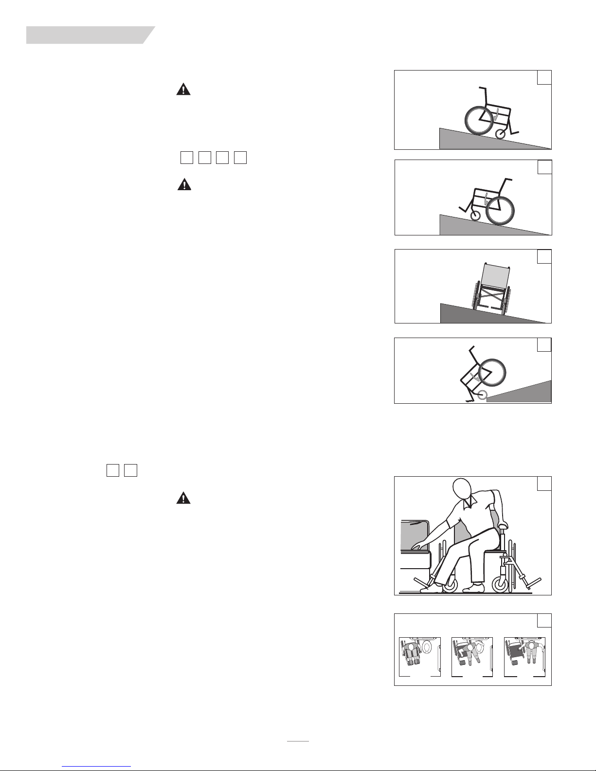
H. RAMPS, SLOPES & SIDEHILLS
3 4 5 6
WARNING
Whenever possible, avoid riding on a slope, which includes a ramp or sidehill. This will change the center of balance of your chair. Your chair is less stable and more difficult to manuever when it is at an
angle. When moving up a hill, anti-tip tubes may not prevent a fall or tip-over. Always ask for help when
riding on slopes.
Do not
1.
2. Avoid Sidehills.
3.
4.
5.
6.
7.
8. To Reduce The Risk Of A Fall Or Tip-Over:
9. Ramps at home & work– For your safety, ramps at home and work must meet all legal require-
10. When you have to use a ramp, always stay in the CENTER of the ramp. Make sure the ramp is
If you fail to heed these warnings, damage to your chair, a fall, tip-over or loss of control may occur and
cause severe injury to the rider or others.
use your chair on a slope steeper than 10°.
Do not
Always
go straight up or straight down a slope.
Do not
turn or change direction on a slope.
Do not
stop on a steep slope. If you stop, you may lose control of your chair.
NEVER
use rear wheel locks to try to slow or stop your chair. This is likely to cause your chair
to veer out of control.
ALWAYS
a. Wet or slippery surfaces.
b. A change in grade on a slope (or a lip, bump or depression). These may cause a fall or tip-
c. A drop-off at the bottom of a slope or ramp. A drop-off as small as 3/4 inch can stop a
a. Lean or press your body UPHILL. This will help adjust for the change in the center of balance
b. Keep pressure on the handrims to control your speed on a down slope. If you go too fast
c. Ask for help any time you are in doubt.
ments for your area:
a. Avoid a drop off. You may need a section at the top or bottom to smooth out the transition.
b. Stay in the center of the ramp and control your speed.
wide enough so that you have no risk of going off the edge.
be aware of:
over.
front caster and cause the chair to tip forward.
caused by the slope or sidehill.
you may lose control.
use your chair on a sidehill with a slope steeper than 6°.
Do not
“cut the corner” on a slope or ramp.
Downslope less than 10°
Straight down
Control Speed
Go Slow
No Turns
Upslope less than 10°
Lean Forward
Straight up
Don’t stop
No Turns
Sidehill less than 6°
Don’t stop
No Turns
Ramps
Straight Down
Stay centered
No Drop-offs
Go Slow
3
4
5
6
I. TRANSFER
7 8
WARNING
It is dangerous to transfer on your own. It requires good balance and agility. Be aware that there is a
point during every transfer when the wheelchair seat is not below you. To Avoid A Fall:
1. Work with your health care advisor to learn safe transfer methods
a. Learn how to position your body and how to support yourself during a transfer.
b. Have someone help you until you know how to do a safe transfer on your own.
2. Lock the rear wheels before you transfer.
3. Be aware that the chair can still slide and/or tip. The wheel lock keeps the rear wheels from
rolling while you are perforrming the transfer.
4. Make sure that the pneumatic tires are properly inflated. Low tire pressure may allow the rear
wheel locks to slip. (see table in Section G “Pneumatic Tires”
5. Move your chair as close as you can to the seat you are transferring to.
If possible, use a transfer board.
6. Rotate the front casters until they are as far forward as possible.
7. If you can, remove the footrests, or swing them out of the way.
a. Make sure your feet do not catch in the space between the footrests.
b. Avoid putting weight on the footrests as this may cause the chair to tip.
8. Make sure armrests are removed, or out of the way and do not interfere with the transfer.
9. Transfer as far back onto the seat surface as you can. This will reduce the risk that the chair will
tip or move away from you.
If you fail to heed these warnings, damage to your chair, a fall, tip-over or loss of control may occur and
cause severe injury to the rider or others.
Optimum Transfer position
1.
2. 3.
Before transferring, remove the armrests, and footrests, and make sure the
wheel lock is set.
7
8
MK-100151 Rev. A
8
Page 9

ENG LIS H
VI. SAFETY WARNINGS: FALLS & TIP-OVERS
J. CURBS & SINGLE STEPS
9
WARNING
Before riding over curbs, or negotiating even a single step, ALWAYS ask for assistance first. Curbs and steps
can cause tipping and serious bodily harm. When in doubt as to our ability to avoid, or traverse any obstacle,
ALWAYS ask for help. Be aware of your riding skills and personal limitations, develop new skills only with the
help of a companion.
For Attendant:
1. Do not try to climb a high curb or step (more than 4 inches high) UNLESS you have help. Doing so may
cause your chair to exceed its balance point and tip over.
2. With the help of an attendant, go straight up and straight down a curb or step. If you climb or descend
at an angle, a fall or tip-over is likely.
3. Be aware that the impact of dropping down from a curb or step can damage your chair or loosen fasteners.
If you fail to heed these warnings damage to your chair, a fall, tip-over or loss of control may occur and can
possibly cause severe injury to the rider or others.
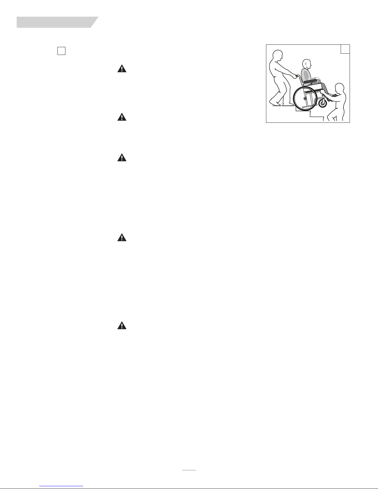
K. CLIMBING A CURB OR SINGLE STEP
Each person who assists the rider with curbs and steps should read and follow all instructions and warnings pertaining to attendants, and caregivers.
9
WARNING
For Attendant:
1. Stay behind the chair.
2. Continue backward until the rear wheels contact the face of the curb or step. Lift and roll the rear
wheels to the top of the curb.
3. Pull the chair backwards until the caster wheels have cleared the edge of the curb and return the chair
to it’s rolling position.
If you fail to heed these warnings damage to your chair, a fall, tip-over or loss of control may occur and cause
severe injury to the rider or others.
L. DESCENDING A CURB OR SINGLE STEP
follow these steps to help the rider climb a curb or single step going BACKWARD:
9
9
WARNING
For Attendant::
1. Stay at the rear of the chair.
2. Several feet before your reach the edge of the curb or step, tip the chair slightly and pull it backward.
3. When the chair is at it’s balance point, carefully step forwards until the rear wheels reach the edge of
the curb or step. Then allow the rear wheels to slowly roll down onto the lower level.
4. Push the chair forward until you are standing on the lower level.
5. When the rear wheels are safely on the lower level, tilt the chair back to its balance point.
If you fail to heed these warnings damage to your chair, a fall, tip-over or loss of control may occur and cause
severe injury to the rider or others.
If you fail to heed these warnings, damage to your chair, a fall, tip-over or loss of control may occur and cause
severe injury to the rider or others.
Follow these steps to help a rider descend a curb or single step going FORWARD:
9
MK-100151 Rev. A
Page 10
ENG LIS H
VI. SAFETY WARNINGS: FALLS & TIP-OVERS
M. STAIRS
10
WARNING
1. NEVER use this chair on stairs UNLESS you have someone to help you. Doing so is likely to cause a
fall or tip-over.
2. Negotiating stairs with a wheelchair always requires at least 2 attendants for safety.
If you fail to heed these warnings, damage to your chair, a fall, tip-over or loss of control may occur and cause
severe injury to the rider or others.
WARNING
Before you assist a rider, be sure to read the warnings “For Attendants” in Section V, Part K and follow all
instructions that apply. Be aware that you will need to learn safe methods best suited to your abilities.
N. CLIMBING STAIRS
WARNING
1. Use at least two attendants to move a chair and rider up stairs.
2. Move the chair and rider BACKWARD up the stairs.
3. The person at the rear is in control. He or she tilts the chair back to its balance point.
4. A second attendant at the front firmly grasps a non-detachable part of the front frame and lifts the chair
up and over one stair at a time.
5. The attendants move to the next stair up. Repeat for each stair, until you reach the landing.
If you fail to heed these warnings, damage to your chair, a fall, tip-over or loss of control may occur and cause
severe injury to the rider or others.
O. DESCENDING STAIRS
10
1. Use at least two attendants to move a chair and rider down stairs.
2. Move the chair and rider FORWARD down the stairs.
3. The person at the rear is in control. He or she tilts the chair to the balance point of the rear wheels
and rolls it to the edge of the top step.
4. A second attendant stands on the third step from the top and grasps the chair frame. He or she lowers the chair one step at a time by letting the rear wheels roll over the stair edge.
5. The attendants move to the next stair down. Repeat for each stair, until you reach the landing.
If you fail to heed these warnings, damage to your chair, a fall, tip-over or loss of control may occur and cause
severe injury to the rider or others.
P. TILT USE AND BACK ANGLE ADJUSTMENT (MONO BACK)
WARNING
BEFORE you operate the tilt mechanism, or back angle adjustment (MONO back):
1. Always verify that the arms of the rider are stable on the armrests or within the armrests.
2. Always verify that the legs of the rider are stable on the footrest/legrest.
3. Never place hands, feet or foreign objects into the tilt mechanism.
4. Never push or propel the chair with the seat tilted in a forward position.
5. Never add chair accessories that are not specifically designed for the IRIS.
6. Never exceed a tilted position that aligns the backrest parallel to the ground.
If you fail to heed these warnings, damage to your chair, a fall, tip-over or loss of control may occur and cause
severe injury to the rider or others.
WARNING
MK-100151 Rev. A
10
Page 11
ENG LIS H
VII. WARNINGS, COMPONENTS & OPTIONS
A. ANTI-TIP TUBES (OPTIONAL)
WARNING
Anti-tip tubes can help keep your chair from tipping over backward in
normal conditions.
1. Sunrise recommends the use of anti-tip tubes:
2. When locked in place (in the “down” position) anti-tip tubes should
be BETWEEN 1 1/2 to 2 inches off the ground.
a. If set
b. If set
3. If you have to climb or descend a curb, or overcome an obstacle, it
may be necessary to have an attendant make sure the anti-tip tubes
are rotated up, and out of the way, so that the chair and rider do
not get stuck and/or become unstable.
If you fail to heed these warnings damage to your chair, a fall, tip-over or
loss of control may occur and cause severe injury to the rider or others.
higher
than 2 inches, they may not prevent a tip-over.
lower
than 1 1/2 inches, they may “hang up” on obstacles
and cause a fall or tip over.
B. ARMRESTS
WARNING
Armrests detach and will not bear the weight of this chair.
1. NEVER lift this chair by its armrests. They may come loose or break.
2. Lift this chair only by non-detachable parts of the main frame.
If you fail to heed these warnings damage to your chair, a fall, tip-over or
loss of control may occur and cause severe injury to the rider or others.
C. PUSH HANDLES
WARNING
When you have a attendant, make sure that this chair has push handles.
1. Push handles provide secure points for an attendant to hold the rear
of this chair, to prevent a fall or tip-over. Make sure to use push handles when you have an attendant.
2. Check to make sure push handle grips will not rotate or slip off.
If you fail to heed these warnings, damage to your chair, a fall, tip-over or loss
of control may occur and cause severe injury to the rider or others.
D. STROLLER HANDLE
WARNING
1. Always keep hands away from the locking mechanism located at the
bottom of the back canes when folding the back down or pulling it
back up.
2. Always keep fingers away from the interior of the hinge when readjusting the adjustable stroller handle.
F. FASTENERS
WARNING
Many of the screws, bolts and nuts on this chair are special high-strength
fasteners. Use of improper fasteners may cause your chair to fail.
1. ONLY use fasteners provided by an authorized supplier (or ones of
the same type and strength, as indicated by the markings on the
heads).
2. Over- or under-tightened fasteners may fail or cause damage to
chair parts.
3. If bolts or screws become loose, tighten them as soon as you can.
If you fail to heed these warnings damage to your chair, a fall, tip-over or
loss of control may occur and cause severe injury to the rider or others.
G. FOOTRESTS
WARNING
1. At the lowest point, footrests should be AT LEAST 2 inches off the
ground. If set too LOW, they may “hang up” on obstacles you can
expect to find in normal use. This may cause the chair to stop suddenly and tip forward.
2. To Avoid A Trip Or Fall When You Transfer:
a. Make sure your feet do not “hang up” or get caught in the space
between the footrests.
b. Avoid putting weight on the footrests, as the chair may tip for-
ward.
c. Footrests should be swung out of the way or removed whenever
entering or exiting the wheelchair.
3. NEVER lift this chair by the footrests. Footrests detach and will not
bear the weight of this chair. Lift this chair only by non-detachable
parts of the main frame.
If you fail to heed these warnings damage to your chair, a fall, tip-over or
loss of control may occur and cause severe injury to the rider or others.
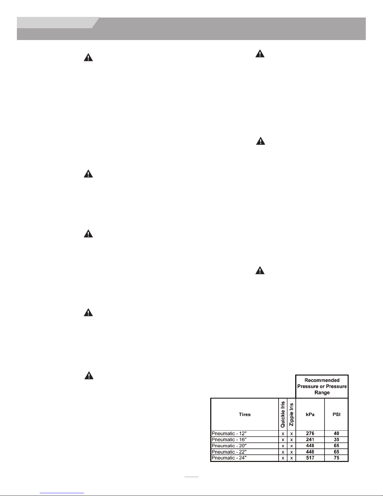
H. PNEUMATIC TIRES
WARNING
Proper inflation extends the life of your tires and makes your chair easier to
use.
1. Do not use this chair if any of the tires is under- or over-inflated. Check
weekly for proper inflation level, as listed on the tire sidewall.
2. Low pressure in a rear tire may cause the wheel lock on that side to slip
and allow the wheel to turn when you do not expect it.
3. Low pressure in any of the tires may cause the chair to veer to one side
and result in a loss of control.
4. Over-inflated tires may burst.
If you fail to heed these warnings, damage to your chair, a fall, tip-over or loss of
control may occur and cause severe injury to the rider or others.
E. CUSHIONS
WARNING
1. Quickie standard foam cushions are not designed for the relief of
pressure.
2. If you suffer from pressure sores or if you are at risk that they will
occur, you may need a special seat system or a device to control your
posture. Consult your doctor, nurse or therapist to find out if you
need such a device for your well-being.
3. Seat pans are not intended to be used as a direct seating surface. A
cushion or other seating surface should be placed on the seat pan
before use.
If you fail to heed these warnings, damage to your chair, a fall, tip-over or
loss of control may occur and cause severe injury to the rider or others.
11
Recommended Tire Pressures
MK-100151 Rev. A
Page 12

ENG LIS H
VII. WARNINGS: COMPONENTS & OPTIONS
I. POSITIONING BELTS (OPTIONAL)
WARNING
Use positioning belts ONLY to help support the rider’s posture. Improper
use of these belts may cause severe injury to or death to the rider.
1. Make sure the rider does not slide down in the wheelchair seat. If
this occurs, the rider may suffer chest compression or suffocate due
to pressure from the belts.
2. The belts must be snug, but must not be so tight that they interfere
with breathing. You should be able to slide your open hand, flat,
between the belt and the rider.
3. A pelvic wedge or a similar device can help keep the rider from sliding down in the seat. Consult with the rider’s doctor, nurse or therapist to find out if the rider needs such a device.
4. Use positioning belts only with a rider who can cooperate. Make
sure the rider can easily remove the belts in an emergency.
5. NEVER Use Positioning Belts:
a. As a patient restraint. A restraint requires a doctor’s order.
b. On a rider who is comatose or agitated.
c. As a motor vehicle restraint. In an accident or sudden stop the
rider may be thrown from the chair. Wheelchair seat belts will
not prevent this, and further injury may result from the belts or
straps.
If you fail to heed these warnings damage to your chair, a fall, tip-over or
loss of control may occur and cause severe injury to the rider or others.
J. QUICK-RELEASE AXLES
WARNING
1. Do not use this chair UNLESS you are sure that both quick-release
rear axles are locked.
2. An axle is not locked until the quick-release button pops out fully. If
the axle is not inserted fully, the wheel may come off during use,
endangering the rider.
3. Quick-release axles should be periodically cleaned and inspected for
function, and signs of wear or bending. Replace as necessary.
If you fail to heed these warnings, damage to your chair, a fall, tip-over or loss
of control may occur and cause severe injury to the rider or others.
K REAR AXLES
WARNING
A change in set-up of the rear wheels will affect the center of balance
of your chair.
1. The farther you move the rear axles FORWARD, the more likely it
is that your chair will tip over backward.
2. Consult your doctor, nurse or therapist to find the best rear axle
set-up for your chair. Do not change the set-up UNLESS you are
sure you are not at risk to tip over.
3. Adjust the rear wheel locks after you make any change to the rear
axles.
a. If you fail to do so, the locks may not work.
b. Make sure lock arms embed in tires at least 1/8 inch when
locked.
If you fail to heed these warnings, damage to your chair, a fall, tip-over or loss
of control may occur and cause severe injury to the rider or others.
L. REAR WHEEL LOCKS
WARNING
Rear wheel locks are NOT designed to slow or stop a moving wheelchair.
Use them only to keep the rear wheels from rolling when your chair is at a
complete stop.
1. NEVER use rear wheel locks to try to slow or stop your chair when
it is moving. Doing so may cause a fall or tip-over
2. To keep the rear wheels from rolling, always set both rear wheel
locks when you transfer to or from your chair.
3. Low pressure in a rear tire may cause the wheel lock on that side to
slip and may allow the wheel to turn when you do not expect it.
4. Make sure lock arms embed in tires at least 1/8 inch when locked. If
you fail to do so, the locks may not work.
If you fail to heed these warnings damage to your chair, a fall, tip-over or
loss of control may occur and cause severe injury to the rider or others.
M. MODIFIED SEAT SYSTEMS
WARNING
Use of a seat system not approved by Sunrise may alter the center of balance of this chair. This may cause the chair to tip over.
1. Do not change the seat system of your chair UNLESS you consult
your authorized supplier first.
2. Use of a seating system not provided by Sunrise is prohibited for
transit use.
If you fail to heed these warnings damage to your chair, a fall, tip-over or
loss of control may occur and cause severe injury to the rider or others.
N. TRAY FOR VENT AND BATTERY
NOTE–
NOTE–
NOTE–
Vent tray only available on the Quickie IRIS.
This option is only compatible with wheelchairs having a mini-
mum floor-to-seat height of 15" (38 cm).
The battery tray components are not compatible with the
Attendant Wheel Lock option or foot release tilt.
WARNING
Never use this wheelchair as a seat in a motor vehicle unless all components are removed from the battery tray, and properly secured
separately in the vehicle.
WARNING
Always contact Technical Service before installing or removing the
battery tray components to obtain the correct assembly locations of
the strut tubes, roller carriage assembly and caster brackets.
WARNING
The combined weight of the user plus the ventilator, battery and tray
components should not exceed 165 lbs (75 kg) on the Zippie IRIS,
250 lbs (114 kg) on the Quickie IRIS, and 350 lbs (159 kg) on the
heavy duty option.
O. ACCESSORY HOOK
MK-100151 Rev. A
WARNING
The weight limit for the accessory hook is 10lbs (total) for all items
If you fail to heed these warnings damage to your chair, a fall, tip-over or
loss of control may occur and cause severe injury to the rider or others.
12
Page 13
ENG LIS H
VIII. USE AND MAINTENANCE
WARNING
The owner and/or Caregiver for the use of this product, is responsible for
making sure that it has been setup and adjusted by a trained service professional under the advice of a healthcare advisor. The chair may require
periodic maintenance or certain in-use adjustments that may be performed
by the owner or caregiver.
A. INTRODUCTION
1. Proper maintenance will improve performance and extend the useful
life of your chair.
2. Clean your chair regularly. This will help you find loose or worn
parts and make your chair easier to use. You will need a mild detergent solution and plenty of cleaning rags.
3. If discovered, repair or replace loose, worn, bent or damaged parts
before using the chair
4. To protect your investment, have all major maintenance and repair
work done by your authorized dealer.
. Insp
ect and maintain this chair strictly per the maintenance chart.
5
. If you detect a problem, make sure to order parts, or have service,
6
and repair work done at your authorized dealer before use.
. At least once per year, have a complete inspection, safety check,
7
and service of your chair made by an authorized dealer.
B. CRITICAL MAINTENANCE TIPS
1. Tire Air Pressure:
Check air pressure in pneumatic tires at least
wheel locks will not grip properly if you fail to maintain the air pressure
shown on tire sidewall.
.
ONCE PER WEEK
. The
D. CLEANING
1. Paint Finish
a. Clean the painted surfaces with mild soap or detergent at least once
a month.
b. Protect the paint with a coat of non-abrasive auto wax every three
months.
2. Axles and Moving Parts
a. Clean around axles and moving parts WEEKLY with a slightly damp
(not wet) cloth.
b. Wipe off or blow away any fluff, dust or dirt on axles or moving
parts.
3. Upholstery
a. Hand-wash (machine washing may damage fabric).
b. Drip-dry only. DO NOT machine dry as heat will damage fabric.
4. Basic Maintenance Materials available at local store
a. Tire Pump
b. Clean rags or cotten cloth.
c. Teflon-based Lubricant
d. Mild Detergent.
NOTE– You do not need to grease or oil the chair.
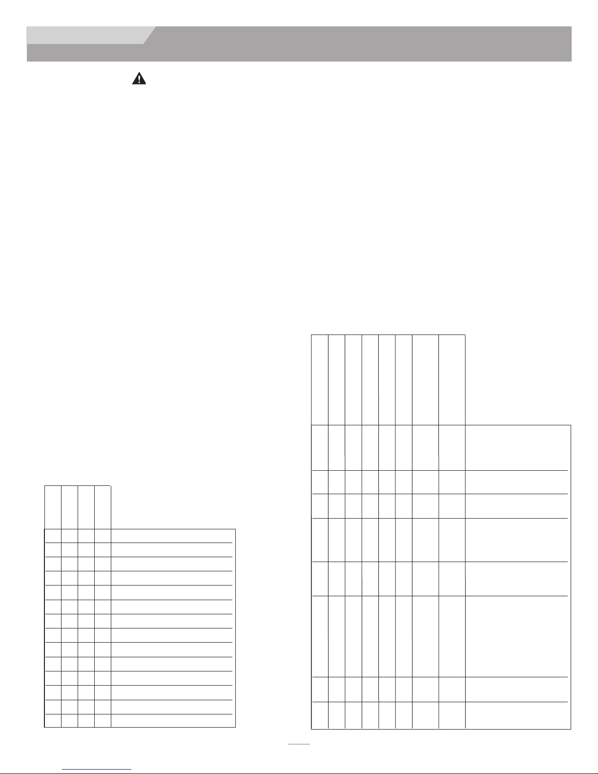
E. TROUBLESHOOTING CHART
2. Axles & Axle Sleeves:
When checking axles and axle sleeves every six months, make sure they
are clean and tight.
Loose sleeves will damage the axle plate and will affect performance.
C. MAINTENANCE CHART
Weekly
3 Months
6 Months
Annually
CHECK...
R Tire inflation level
R Wheel locks
R All fasteners for wear and tightness
R Armrests
R Axle and axle sleeves
R Quick-release axles
R Wheels, tires and spokes
R Casters
R Anti-tip tubes
R Frame
R Rollers
R Tilt cables and plunger
R Rocker arm
Service by authorized supplier
R
SYMPTOMS
Left turn in chair
Right turn in chair
Looseness in chair
Sluggish turning
RR R R
RRRR Make sure all nuts and bolts
RR
R
RR R R
RR R
Squeaks and rattles
Caster flutter
Chair drops fast into tilt
R
and is hard to return.
returns too fast.
Chair is hard to tilt and
SOLUTIONS
Make sure tire pressure is correct and equal in both rear tires
and front caster tires, if pneumatic.
are snug.
Make sure all spokes and nipples
are tight on radial spoke wheels.
Use Tri-Flow Lubricant
(Teflon™-based) between all
modular frame connections and
parts.
Check for proper caster plate
adjustment. See instructions for
caster plate adjustment.
Make sure both front casters
touch the ground simultaneously. If they do not, add the proper
spacers between the bottom
bearing of the caster plate and
fork stem nut until they do.
Make sure you check for this
problem on a flat surface.
Consult with an authorized supplier to adjust CG/CR forward
Consult with an authorized sup-
R
plier to adjust
13
MK-100151 Rev. A
Page 14
ENG LIS H
VIII. USE AND MAINTENANCE
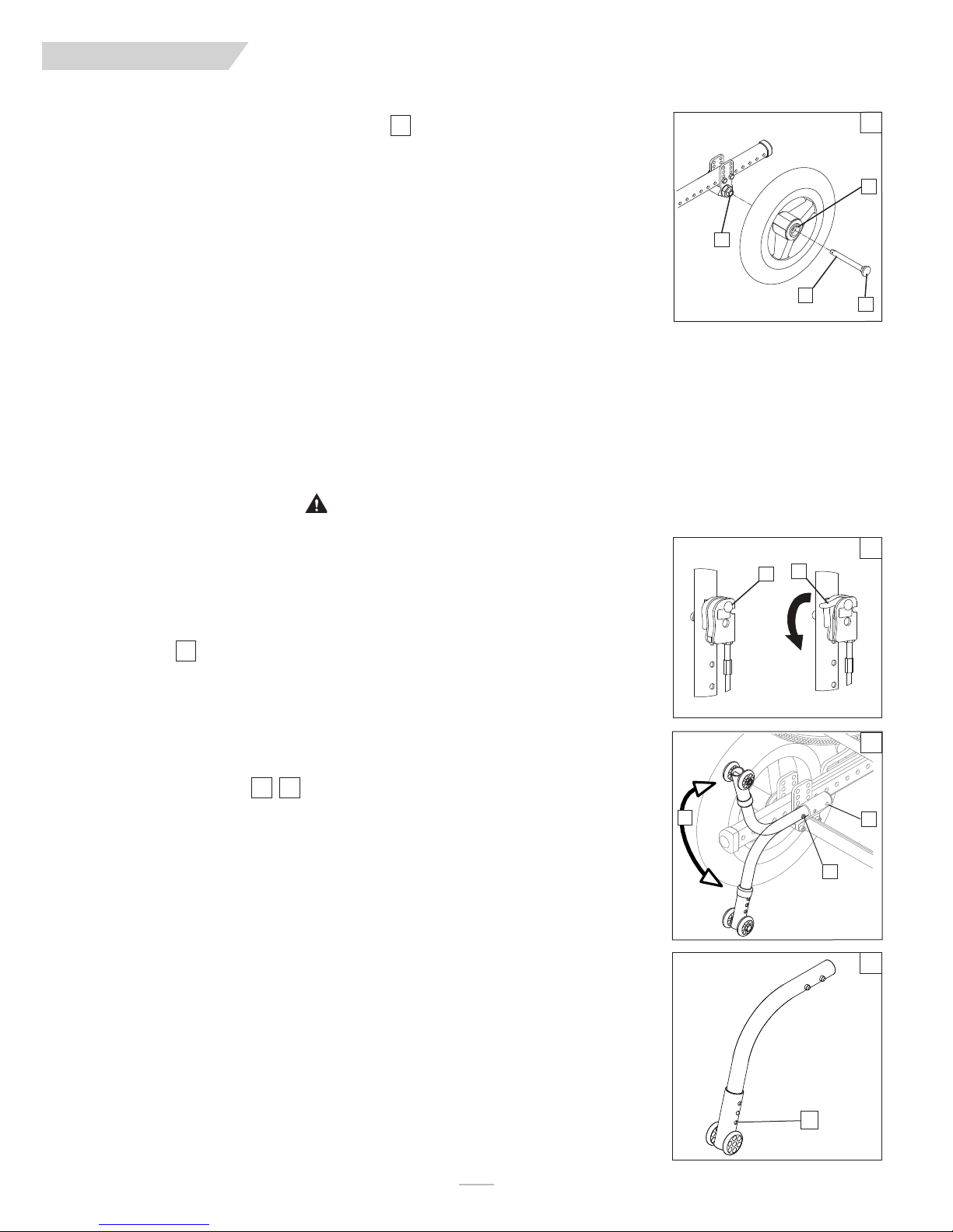
F. TO MOUNT AND REMOVE REAR WHEELS
Do not use this chair UNLESS you are sure both quick-release axles are locked. An unlocked axle may come off
during use and cause a fall.
NOTE–
Axle is not locked until the quick-release button (A) pops out fully.
11
2. To Install Wheel
a. Depress quick-release button (A) fully. This will release tension on ball bearings at other end.
b. Insert axle through hub of rear wheel (B).
c. Keep pressure on button (A) as you slide axle (C) into axle sleeve (D).
d. Release button to lock axle in sleeve. Adjust axle if it does not lock.
e. Repeat steps on other side.
3. To Remove Wheel
a. Depress quick-release button (A) fully.
b. Remove wheel by sliding axle (C) out of axle sleeve (D).
c. Repeat steps on other side.
G. CUSHION INSTALLATION
a. Place cushion on seat pan with hook material side down. The beveled edge of the cushion should be in
front, press it firmly into place.
H. WHEEL LOCKS
WARNING
Wheel locks are installed at Sunrise and should be adjusted by your qualified service person. Inspect wheel locks
weekly per the maintenance chart. Do not use your chair UNLESS you are sure both wheel-locks can fully engage. A
wheel-lock that is not correctly adjusted may allow your chair to roll, or turn unexpectedly. Wheel-locks must be
adjusted after making sure the tires have the correct air pressure. When fully engaged, the arm should be imbedded
into the tire at least 1/8” to be effective. If you find the wheel locks have slipped or are not working correctly contact
your service provider for proper adjustment.
11
B
D
C
A
12
F
E
I . HUB LOCK
12
To operate Hub Lock
1. To Lock rear wheels, press button (E). Lever (F) will flip outward. Do not engage hub lock when chair is in
motion
2. To unlock wheels, press Lever (F) back down until Button (E) pops back out. Each lever operates one side of the
chair. To fully lock chair, both buttons must be pushed.
J. ANTI-TIP TUBES- REAR
Anti-tip tubes are recommended for all wheelchairs. Do not attempt to overcome Obstacles on your own.
1413
1. Inserting Anti-Tip Tubes Into Receivers
a. Press in the rear anti-tip button(G) on the anti-tip so that both buttons are drawn inside.
b. Insert the anti-tip tube into the receiver (H).
c. Turn the anti-tip tube down until front release button pops through the receiver mounting hole.
d. Insert second anti-tip tube the same way.
2. Turning Anti-Tip Tubes Up
Turn the anti-tip tubes up when being pushed by attendant, and overcoming obstacles or climbing curbs.
a. Press in the rear anti-tip tube release button (G).
b. Hold button (G) in and turn anti-tip tube up (I).
c. Release the button.
d. Repeat with second anti-tip tube.
e. Remind attendant to return anti-tips to the down position after completing the maneuver.
3. Adjusting Anti-Tip Tube Wheel
The anti-tip tube wheels may have to be raised or lowered to achieve proper ground clearance (1-1/2" to 2").
a. Press the anti-tip wheel release button (J) so that the release pin is drawn inside.
b. Raise or lower to one of the three or six pre-drilled holes.
c. Release the button (J).
d. Adjust the second anti-tip tube wheel the same way. Both wheels should be at exactly the same height.
13
I
H
G
14
J
MK-100151 Rev. A
14
Page 15
ENG LIS H
VIII. USE AND MAINTENANCE
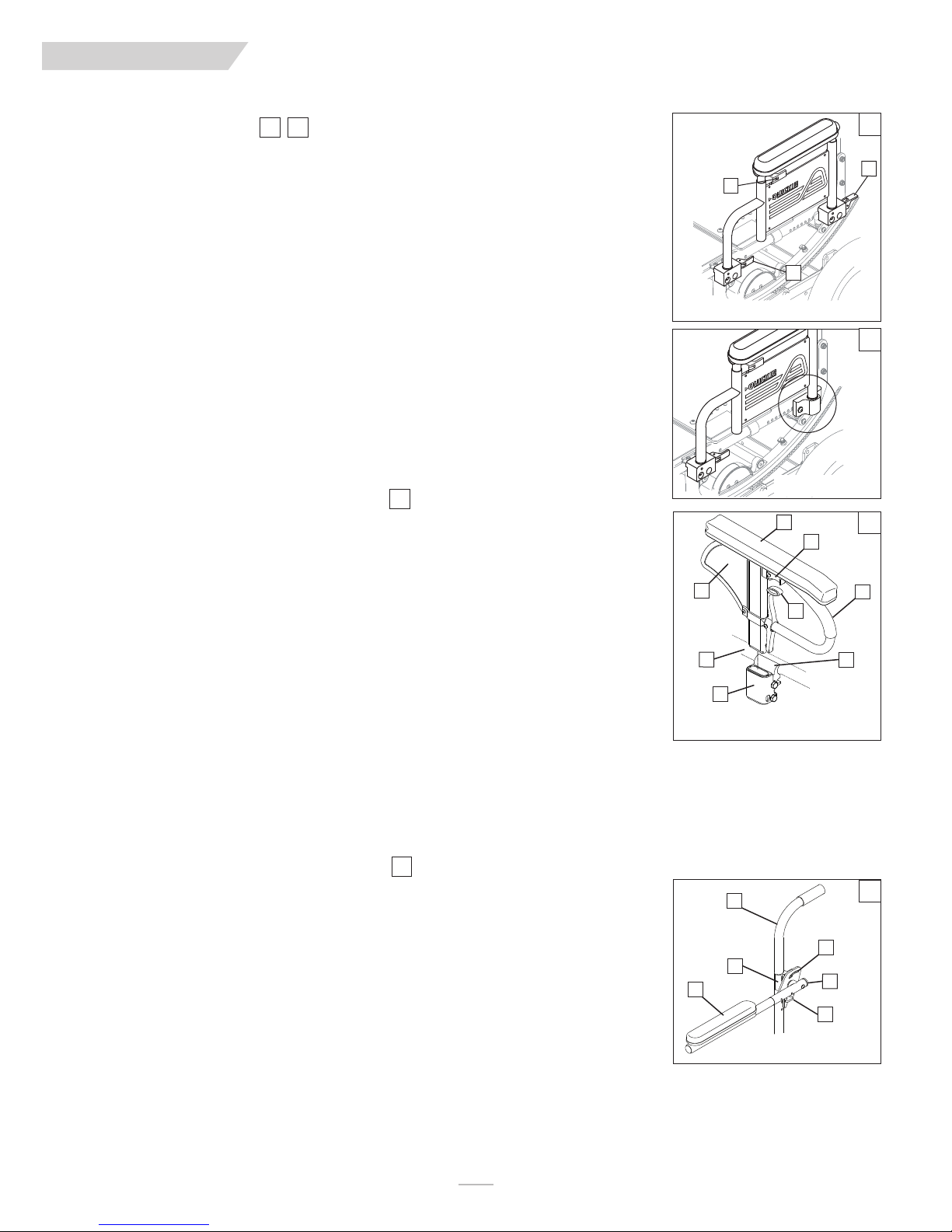
K. DUAL-POST ARMRESTS
1615
1. Installation or Removal
a. The assembly is held securely in place when the securing lever (A) is facing outside.
b. Pull front securing lever (A) forward to release.
c. Insert or remove armrest.
d. Return securing lever to locked position.
2. Height-Adjustment (optional)
a. Release the upper securing lever (C).
b. Set armrest at desired height.
c. Return securing lever to locked position.
d. Move armrest up or down to allow armrest to snap into place.
3. Flip Back (optional)
a. Release the front securing lever only (A).
b. Flip the armrest back, it remains attached to the rear receiver.
c. To detach armrest completely pull rear securing lever (B) up.
d. Move armrest down into place.
e. Return securing lever to locked position.
L. HEIGHT-ADJUSTABLE ARMRESTS (optional)
17
1. Installation
a. Slide the outer armpost (1) into the receiver(7) mounted to the wheelchair frame.
b. The armrest will automatically lock into place.
2. Height Adjustment
a. Rotate release lever (2) to second stop.
b. Slide armrest pad (4) up or down to desired height.
c. Return lever (2) to locked position against armpost.
d. Push arm pad down until upper armpost locks firmly into place.
3. Removing Armrest
a. Grip release lever (3) and pull up to remove the armrest.
C
Flip-Back receivers
6
1
7
A
Fixed receivers
4
2
3
8
15
B
16
17
5
M. ADJUSTABLE LOCKING FLIP-UP ARMRESTS
1. Flip up and down
a. Release the upper securing lever (2).
b. Flip the armrest back (1), it remains attached to the back post.
c. Move armrest down into place.
d. The lever (2) locks itself in position automatically.
Height adjustable single post
1. Outer armpost
2. Release Lever Height
3. Release lever
4. Armrest pad
5. Transfer bar
6. Side panel
7. Receiver
18
8. Clamp
6
5
1
Adjustable Locking Flip-Up
1. Armrest Pad
2. Upper Securing Lever
3. Flip-back tube
4. Angle Adjust Bracket
5. Clamp
6. Back cane
18
4
3
2
15
MK-100151 Rev. A
Page 16

ENG LIS H
VIII. USE AND MAINTENANCE
N. CANTILEVER ARMRESTS
19
1. Flip Back the armrest for access and transfers.
a. Release the armrest (A) by pulling up on the securing lever (this will unlock the armrest).
b. Rotate the armrest back.
2. Return the armrest to the riding position
a. Rotate the armrest back to riding position.
b. Be sure to lock the armrest by returning the securing lever to It’s locked position.
NOTE–
Figure shows Lever(A) in locked position.
O. SWING-AWAY HANGERS/FOOTRESTS
20
Swing-in-Swing-out Hangers and Footrests (60°, 70º, 80°)
1. Installation
a. Place swing-in/swing-out pivot saddle into the receiver (A) on front frame tube with the footrest
facing inward or outward from the frame.
b. Rotate the footrest inward until it locks into place on locking plate.
2. Removal
a. To remove footrest, release latch (B) by pulling lever upward or pushing lever downward.
b. Rotate footrest inward or outward and lift.
19
A
20
B
A
P. HEAVY-DUTY, LIFT-OFF FOOTRESTS (optional)
21
1. Installation
Slide pivot saddle (C) into receiver (D) on front frame tube until it locks into place.
2. Removal
To remove footrest, push release latch (E) while lifting up footrest from receiver.
Q. ARTICULATING LEGREST (optional)
22
1. Installation or Removal
To install or remove Articulating Legrest (ALR) see instructions for Swing-away Footrest installation.
2. Elevation Adjustment
a. To raise legrest, lift to desired position. Legrest will automatically lock in place.
b. To lower legrest, while seated in chair, press release lever (F) down and lower Legrest to desired position.
Legrest will automatically lock in place.
3. Height Adjustment of the Calf Pad
a. Rotate the tube clamp (G) towards the outside.
b. Slide calf pad assembly up or down.
c. Rotate calf pad assembly (H) back in the desired indented position.
21
D
C
F
G
E
22
H
MK-100151 Rev. A
16
Page 17

ENG LIS H
VIII. USE AND MAINTENANCE
R. ELEVATING LEGREST (optional)
23
1. Installation or Removal
To install or remove Elevating Legrest (ELR) see instructions for Swing-away Footrest
installation.
2. Elevation Adjustment
a. To raise legrest, lift to desired position. Legrest will automatically lock in place.
b. To lower legrest, while seated in chair, press release lever (I) down and lower legrest to desired position.
Legrest will automatically lock in place.
S. TILT-IN-SPACE MECHANISM
The tilt-in-space mechanism is installed by Sunrise. Two cable/trigger mechanisms positively lock the chair in
place from -5º to 60º depending on the set-up. The Quickie/Zippie IRIS has the capability to provide from 0º to
5º of forward tilt. DO NOT ATTEMPT TO MAKE THIS ADJUSTMENT. This adjustment must be done by an
authorized supplier.
24
1. Trigger Tilt Operation
a. Depressing both triggers (A) at the same time disengages the locking mechanism and allows the seat and
back to rotate in space. Releasing the triggers positively locks the rockers in place.
b. The approximate degree of tilt the seat is at can be seen on the tilt indicator (C).
c. To lock out the tilting function, insert the locking pin (B) into the trigger holder.
I
23
24
A
B
C
2. Foot Release
a. Depressing foot pedal (D) disengages the locking mechanism and allows the seat and back to rotate in
space. Releasing the foot pedal positively locks the rockers in place.
b. The approximate degree of tilt the seat is at can be seen on the tilt indicator (C).
25
17
25
D
MK-100151 Rev. A
Page 18

ENG LIS H
VIII. USE AND MAINTENANCE
T. STROLLER HANDLE EXTENSION (option)
26 27
Installation
a. Press button (E) on the stroller handle so that release pins are drawn inside the tube.
b. Insert the tube into the back tube receiver (F) until the release pin protrudes through the receiver
mounting hole.
U. RECLINING BACK
The dual trigger reclining mechanism is installed by Sunrise.
To Recline or Raise Backrest
a. Depress both triggers (G) at the same time. Releasing the triggers positively locks the backrest in place
within its 60° range.
b. To lock out the adjustment system, insert the locking pin (H) into the trigger holder.
NOTE– ALWAYS
V. MONO BACK STROLLER HANDLE
Height/Angle Adjustment
a. Press button (A) on the stroller handle so that it releases the push handle.
b. Adjust the push handles to a comfortable position.
NOTE– ALWAYS
the locked position.
lock the dual trigger reclining mechanism securely in place after positioning the backrest.
28
lock Push handles by moving them slightly being sure to hear the mechanism click into
F
E
26
27
G
H
28
A
W. FOLDING THE MONO BACK FOR TRANSPORT
29
Height/Angle Adjustment
a. Push down on the release lever(B) and fold the backrest forward for easier transport of the chair.
b. To return the back to the riding position just pull up on the back until it locks into place at the original
position.
NOTE–
AFTER FOLDING OR UNFOLDING THE MONO BACK,
locked position by moving it slightly and listening for the mechanism to click into the locked position.
ALWAYS
check to make sure it is in the
X. CHECK-OUT
Once the wheelchair is assembled and adjusted, it should roll smoothly and easily. All accessories should also
perform smoothly. If you have any problems, follow these procedures:
1. Review assembly and adjustment sections to make sure the chair was properly prepared.
2. Review the troubleshooting guide.
3. If your problem persists, contact your authorized supplier. If you still have a problem after contacting
your authorized supplier, contact Sunrise customer service. See the introduction page located in the
front of this User’s Manual for details on how to contact your authorized supplier, or Sunrise customer
service.
29
B
MK-100151 Rev. A
18
Page 19

ENG LIS H
IX. DEALER SERVICE & ADJUSTMENT.
WARNING
The owner of this chair is responsible for makiing sure that it has been setup and adjusted by a trained service
professional under the advice of a healthcare advisor. Service or adjustments should only be done with the
advice of a healthcare professional. Always use parts and accessories that have been recommended and
approved by Sunrise Medical when servicing this chair.
A. DEALER SERVICE INTRODUCTION
1. At least once per year, this chair should have a complete inspection, safety check, and regular service
made by an authorized dealer.
2. If you have discovered a worn, bent, or damaged part, repair or replace them with recommended parts
before returning this chair to service.
3. All major maintenance and repair work should be done by the authorized dealer.
B. CRITICAL MAINTENANCE TIPS
1. Torque settings:
A torque setting is the optimum tightening which should be made on a particular fastener. It is important to use
proper torque settings where specified. When not specified, torque settings should be 60 in-lbs
2. Dealer Service and Adjustment Reference materials:
Go to www.sunrisemedical.com for parts manuals, instruction sheets, and instructional videos that will aid in the
repair of the Quickie/Zippie Family of wheelchairs.
.
TOOLS YOU WILL NEED
1. Imperial Hex key set
2. Metric Hex key set
3. Imperial Open-end Wrench set
4. Metric Open-end Wrench set
5. Torque wrench
6. Imperial Hex bit Socket set
7. Metric Hex bit Socket set
8. Phillips and Flat screwdrivers
C. CLEANING
1. Paint Finish
a. Clean the painted surfaces with mild soap or detergent.
b. Protect the paint with a coat of non-abrasive auto wax.
2. Axles and Moving Parts
a. Clean around axles and moving parts with a slightly damp (not wet) cloth.
b. Wipe off or blow away any fluff, dust or dirt on axles or moving parts.
c. DO NOT USE 3 in 1 oil, or WD-40 ® for lubrication. Only use Teflon based Lubricant when working on
this wheelchair.
D. REAR AXLE
1. Rear Wheel Axle Adjustment
Tight axle sleeves should be maintained for proper performance of the wheelchair.
a. To adjust the axle (A) you will need a 3/4" wrench (B) to turn the outside axle nuts (C).
b. You will also need a 1/2" wrench to hold the the opposite end of the axle (D), and prevent the axle from
turning, while you are adjusting the nut.
c. Turn the outside axle nut clockwise to tighten.
d. There should only be zero to ten thousandths of an inch (.010") of play.
2. Moving the Rear Axle for Weight Distribution
Weight distribution between the front and rear wheels is primarily adjusted by moving the rear axles forward or
rearward on the frame. Moving the axles REARWARD provides better forward and rearward tipping stability.
Moving the axles FORWARD shifts more of the rider’s weight onto the REAR wheels, providing the following
benefits: the front end of the wheelchair becomes lighter, thus reducing the turning effort, and with a shorter
wheelbase the turning radius is reduced.
CAUTION
before putting the chair into service
IMPORTANT NOTE–
NOTE–
NOTE–
- Moving the Rear axles can effect the stability of the device ALWAYS check stability with the rider
Use a torque setting of 120 in.-lbs. When setting-up the axle plate.
The frame must be kept horizontal when height adjustments are made. Refer to matrix in the ordering
guide for proper setting.
30
The axle adjustment on each side of the chair should be equal.
D
C
B
A
30
19
MK-100151 Rev. A
Page 20

ENG LIS H
IX. DEALER SERVICE & ADJUSTMENT
3. Axle Position Adjustment
a. Remove both wheels from the chair.
b. Remove the bolts (A) from the axle plate (B) on both sides of the chair.
c. Reposition the axle plate in desired position.
d. Insert and tighten bolts (A).
4. Axle Height Adjustment
a. Loosen and remove bolts (A).
b. Set axle at desired height using pre-set holes in the axle plate (B) on both sides.
c. Replace and tighten bolts.
E
. HUB LOCK ADJUSTMENT
31
31
32
To adjust the cables
1. Loosen jam nut (C) using a 10mm wrench.
2. Turn adjustment screw (D) in our out as necessary. Turning screw upward will loosen cable, turning
downward will tighten cable.
3. Re-tighten jam nut (C) against lever mount.
4. Repeat steps 1-3 for opposite side of chair as necessary.
To adjust lever position
1. Remove socket screw (E) and washer (F) from lever and backrest.
2. Choose desired hole in backrest to mount lever and re-install screw and washer.
3. Repeat steps 1-2 for opposite side of chair.
F. WHEEL LOCKS
33
Adjustment
a. Evenly loosen both screws (G). Do not attempt to remove one screw at a time.
b. Slide assembly toward rear wheel until clamp embeds into tire to prevent wheel movement, when in
locked position.
c. Tighten screws (G).
B
A
32
31
E
F
C
D
33
G. SINGLE -POST ARMREST RECEIVER
1. Adjusting Armrest Receiver Fit
To tighten or loosen the fit of the outer armpost in the receiver:
a. Loosen the bolts on the sides of the receiver (J).
b. With the armrest in the receiver, squeeze the receiver to achieve the desired fit.
c. Tighten the four bolts (J).
2. Moving the Receiver location
a. Loosen the 3 bolts (I) holding the clamp halves(H) together (do not remove them)
b. Slide the clamp so that armrest is at the correct position.
c. Tighten the 3 bolts (I).
MK-100151 Rev. A
34
H
G
I
J
34
20
Page 21

ENG LIS H
IX. DEALER SERVICE & ADJUSTMENT
H. ADJUSTABLE LOCKING FLIP-UP ARMRESTS
35
1. Height Adjustment
a. Loosen bolt and nut (A) and remove flip-back tube.
b. Loosen bolts (B, C) and remove clamp (I).
c. Move the clamp (D) up or down to the desired position.
d. Tighten bolts (B, C).
e. Install the flip-back tube back in place and tighten bolts (C,D).
f. Repeat the process for the other armrest.
2. Angle-Adjustment
a. Loosen bolt (E).
b. Set armrest at desired angle using preset holes in armrest angle plate.
c. Tighten bolt (E).
3. Length-Adjustment (optional)
a. Remove foam grip or armpad (G) from armrest.
b. Loosen the nut and screw (F) in the adjustable flip-up tube.
c. Reposition the sleeve (H) at the desired length.
d. Re-tighten the screw and nut (G).
e. Put foam grip or armpad back in place.
I. CANTILEVER LOCKING FLIP-BACK ARMRESTS
36
1. Height Adjustment
a. Using a 5mm hex key and 13mm open end wrench Loosen Button head screw (A) and nut (B) on the
inside of the armrest pivot.
b. Rotate the armrest up or down to a comfortable height and tighten the hardware (A, B).
c. You should repeat the steps on the opposite armrest, and adjust both sides equally in most cases
35
D
I
B
C
G
F
E
H
A
36
B
A
37
D
2. Level the armrest
37
When you adjust the armrest height, you will also need to Level the armrest pad.
a. Using a 5/32” hex key, Loosen the front pivot socket screw (F) and remove the rear socket screw (F)
from the bracket(E) so that you can level the armpad(D).
b. Once you have found the correct adjustment, Re-insert the rear socket head screw(F), and tighten the
hardware.
3. Armrest Pad Adjustments
3938
You can adjust the armrest pad forward or backwards.
a. Using a 1/8” hex key loosen the two button head screws(C) holding the armrest pad(D) to the adjust-
ment bracket (E), and move the pad forwards or backwards.
b. When you have found the right position, Re-insert the screws(C) and tighten the hardware.
You can also adjust the armrest pad laterally.
a. Using a 5/32” hex key remove the two screws(C) holding the armrest pad(D) to the adjustment bracket
(E).
b. You can achieve an inch of adjustment laterally by Flipping the pad 180° as shown.
c. If you still need more adjustment laterally, you can re-position the Armrest pad bracket by removing the 2
socket head screws(F) that hold the bracket to the cantilever arm, and attaching the bracket on the out-
side of the cantilever arm as shown.
d. When you have found the right position, Re-insert the screws(F) and tighten the hardware.
F
E
38
E
F
D
E
C
F
39
21
MK-100151 Rev. A
Page 22

ENG LIS H
IX. DEALER SERVICE & ADJUSTMENT
J. SWING-AWAY HEIGHT ADJUSTMENT
40
Height Adjustment
NOTE–
K. HEAVY DUTY LIFT-OFF FOOTREST
It is recommended that you maintain a minimum of 2.0 inches between the lowest point on the
footrest and the floor.
a. Loosen set screw (J) using a 3/16 inch hex key.
b. Slide footrest extension (K) up or down inside frame tube to desired height.
c. Tighten set screw (J). Use a torque setting of 144 in-lbs (16.27 Nm).
41
Height-Adjustment, Front Mount
a. Loosen and remove the retaining bolt (L) and nut (M) in the footrest mounting bracket.
b. Position footplate upward or downward in predrilled holes on hanger tube.
c. Reinsert bolt and nut and tighten.
L. ARTICULATING LEGREST
42
1. Height Adjustment of the Calf Pad
a. Loosen the retaining nut (N) located at the back of the calf pad bracket assembly.
b. Slide the calf pad bracket assembly up or down.
c. Tighten the retaining nut (N) once the pad is in the desired position.
Height Adjustment with Extension Tube
a. (See “Swing-away Height Adjustment” Section I)
40
J
K
41
M
L
42
M. ELEVATING LEGREST
43
1. Height Adjustment of the Calf Pad
a. Loosen the retaining nut (O) located at the back of the calf pad bracket assembly.
b. Slide the calf pad bracket assembly up or down.
c. Tighten the retaining nut (O) once the pad is in the desired position.
2. Height Adjustment with Extension Tube
a. (See “Swing-away Height Adjustment” Section I)
N
43
O
MK-100151 Rev. A
22
Page 23

ENG LIS H
IX. DEALER SERVICE & ADJUSTMENT
N. CONTRACTURE FOOTREST
1. Outside Mount -
2. Inside Mount -
3. Height Adjustment
a. Loosen and remove the retaining bolt (A) in the footrest mounting bracket.
b. Slide the lower tube upward or downward to the desired position until predrilled holes on hanger tubes
are aligned.
c. Reinsert bolt (A) and tighten.
4. Footrest Angle Adjustment
a. Loosen the retaining bolt (B) in the adjustment locking joint.
b. Position footrest foreword or rearward in desired angle.
c. Retighten the bolt (B).
5. Footplate Angle Adjustment
a. Loosen the retaining bolt (C) in the footplate locking joint.
b. Position footplate upward or downward in desired angle.
c. Retighten the bolt (C).
Can be mounted laterally
Can be mounted in the center.
46
46
46
464544
44
45
O. TILT-IN-SPACE MECHANISM
The tilt-in-space mechanism is installed by Sunrise. Two cable/trigger mechanisms positively lock the chair in
place from -5º to 60º depending on the set-up. The Quickie/Zippie IRIS has the capability to provide from 0º to
5º of forward tilt.
their own
The Caregiver or User of this chair should not attempt to make a forward adjustment on
. This adjustment must be performed by an authorized supplier.
44
4
5
46
B
A
C
47
1. Rocker Cover removal
a. Remove the (4 or 5) screws (D) that hold the cover to the Rocker Frame (E).
b. Remove the Rocker Cover (F) and store with screws in case you need them later.
2. Tilt-stops Adjustment
NOTE– When using tilt stops, you must first remove the Rocker Cover.
Adjustments can be made to limit the amount of tilt (rotation) that the chair provides by using the tilt-stops (H).
a. Loosen and remove the retaining screw (G).
b. Locate the tilt-stops to the desired limit either anterior or posterior.
c. Each half of tilt stop assembly should plug into directly opposing holes on the rocker (E), then secure in
place by tightening the screw (G).
3. Cable Adjustment
NOTE–
Do not use lubricants on the components or assembly.
a. Loosen the jam nut (I).
b. Rotate the cable adjuster (J) until slack is removed from the cable. Make sure the plunger pin can fully
extend and retract after adjustment and that pins engage the rocker when triggers are released.
c. Tighten jam nut (I).
47
48
49
F
E D
E
H
G
48
49
J
I
23
MK-100151 Rev. A
Page 24

ENG LIS H
IX. DEALER SERVICE & ADJUSTMENT
P. STANDARD BACKREST
1. Angle Adjustment
a. Loosen rear bolt (A).
b. Loosen and remove angle adjustment bolt (B).
c. Set backrest at desired angle using pre-set holes.
d. Replace and tighten the front bolt (B).
e. Tighten rear bolt (A).
f. Repeat on other side.
IMPORTANT NOTE–
NOTE–
NOTE–
Use a torque setting of 240 in.-lbs. When setting-up the angle adjustment of the stroller handle.
Backrest position may also need adjusting to maintain optimal CG alignment and stability.
2. Flip-Down Back Function
a. To fold the back down, pull-up the back release pins (J) and push the backrest forward.
b. To lock it back in position, lift the backrest firmly until it locks in its original position.
3. Dynamic Backrest Elastomer Replacement
a. Remove socket head screw (C) and lock nut (D).
b. Using a flat head screw driver, gently pry out the elastomer (E) as shown.
c. Firmly press the new desired elastomer into place, and align holes in elastomer with holes in plate (F).
d. Replace and tighten screws removed above.
50
The adjustment on each side of the chair should be exactly equal.
51
52
50
A
B
51
J
C
F
52
WARNING
If the chair is equipped with the Dynamic Backrest option, the lockout feature must be in the locked position on
both push handles prior to any type of transport of the chair.
4. Dynamic Backrest Lock Engagement
a. Pull key ring (G) and swing lock downward to unlock backrest.
b. Swing lock upward to lock the backrest.
Q. MONO BACK
1. Backrest Height Adjustment
a. Using a 5/32” hex key, Loosen the 4 button head screws(H).
b. Grip the backshell and bracket assembly. It should move freely up or down the Mono back spine.
c. Set the backrest assembly to the preferred height.
d. Tighten all 4 of the button head screws (H).
NOTE–
NOTE–
Use a torque setting of 60 in.-lbs. When setting-up the height adjustment of the Mono Back.
Anytime the Backrest position changes, it is a good idea to verify that the optimal CG alignment and
stability is maintained.
54
53
E
Unlocked
H
D
53
G
Locked
54
MK-100151 Rev. A
24
Page 25

ENG LIS H
IX. DEALER SERVICE & ADJUSTMENT
2. Backshell Height Adjustment
The backshell has additional height adjustment with it’s mounting bracket.
a. Remove the backrest cover.
b. Using a 10mm open end wrench, remove the 4 nuts(A) that hold the backshell to the Mono back
bracket.
c. Remove the 2 nutplates, and reposition them in available holes(B) up or down on the backshell.
d. Thread the nuts from the rear of your chair, and tighten them to finish the adjustment.
3. Backshell Angle Adjustment
The backshell has +/- 4° of angle adjustment with it’s mounting bracket.
a. Using a 5/32” hex key, loosen the 2 button head screws(C)
b. Using a 5/32” hex key loosen the 2 button head pivot screws(D).
c. You can now tilt the backshell forward or rearward.
d. Tighten the screws to finish the adjustment.
4. Tilt Adjustment with the Mono back post and J bracket
The Mono back has additional angle/tilt adjustment through the J bracket.
a. Using a 3/16 hex key/socket wrench loosen the 2 outside J bracket screws(E)
b. Using a 5/16” hex key, rotate the Larger J bracket socket screw clockwise for Recline, and counter-
clockwise for the upright position.
c. Set the adjustment using the 3/16” hex key to tighten the 2 outside screws(E) to 60 in-lb.
55
56
57
55
A
B
56
D
C
57
5. Lateral Backrest Adjustment with the Mono back post and J bracket
The Mono back adds additional lateral adjustment using the J bracket.
a. Using a 3/16 hex key/socket wrench loosen the 2 outside J bracket screws(E)
b. Grasp the backshell and J bracket from behind and move the assembly left or right to the desired area
of support.
c. Set the adjustment using the 3/16” hex key to tighten the 2 outside screws(E) to 60 in-lb.
R. DYNAMIC MONO BACK
If you have a chair with a Dynamic back function, you can utilize the elastomer inserts by releasing the locking
lever.
IMPORTANT NOTE–
BEFORE
a.
from the rider. Transfer the user to a safe location while this task is performed.
b. The Dynamic function can be used by pulling on the lockout lever(H) and rotating the lockout bracket
( I ) down and out of the way.
c. Repeat the step above for the other side of the lockout system, so that both lockouts are released.
d. To lockout the dynamic back for a more rigid support, rotate the lockout bracket ( I ) up while pulling
out on the lockout lever (H).
e. Make sure that it “Clicks” into place for a positive lockout.
DO NOT convert to a dynamic back with the rider in the chair.
locking, or releasing the lockouts (G) make sure there is no pressure on the back support
58
57
E
F
58
H
G
I
25
MK-100151 Rev. A
Page 26
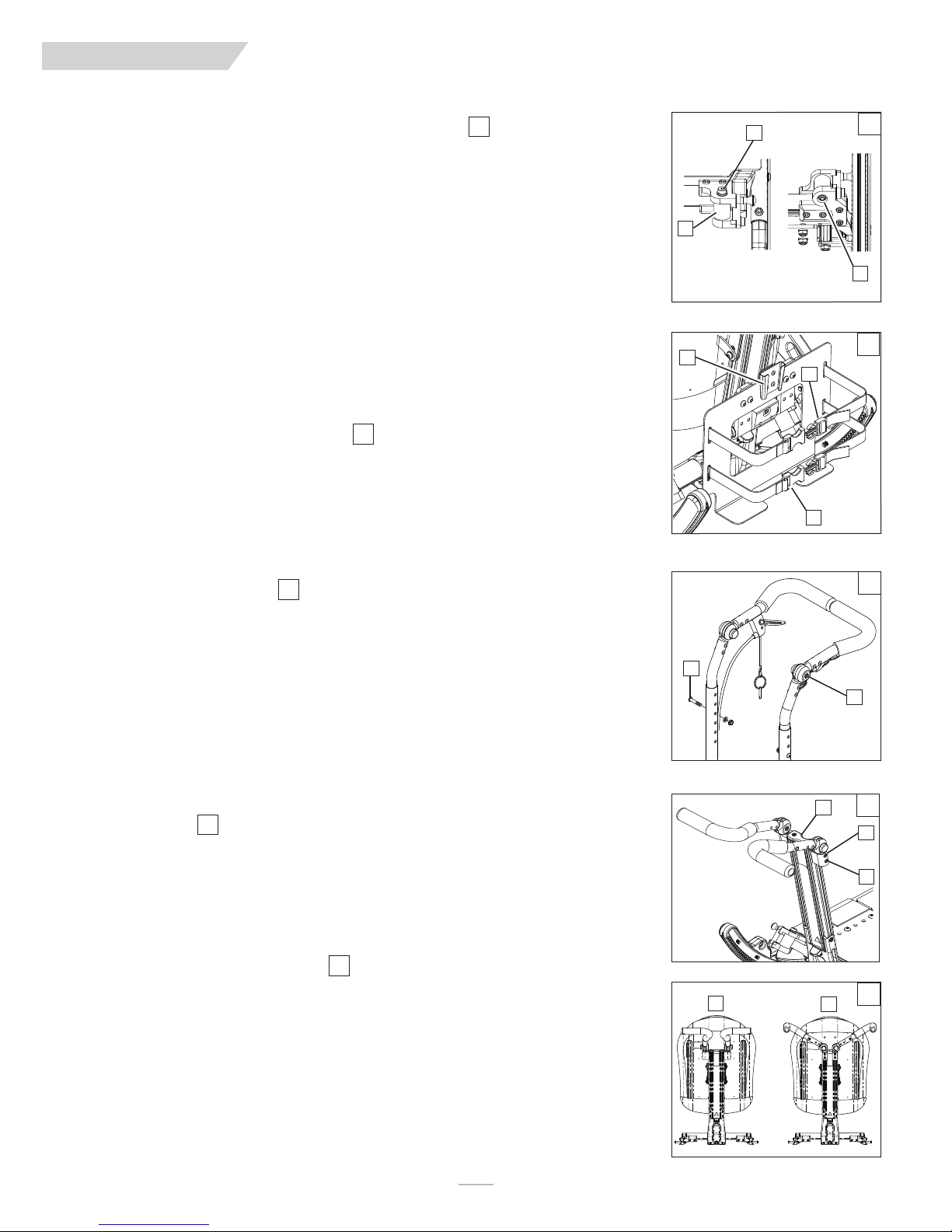
ENG LIS H
IX. DEALER SERVICE & ADJUSTMENT
S. DYNAMIC MONO BACK (ELASTOMER REPLACEMENT)
There are four Elastomer stiffnesses available. Two types are provided with your chair. If your Elastomer gets
worn out, or you need a different level of support, you can replace the elastomer with a few easy steps.
IMPORTANT NOTE–
BEFORE
a.
b. The elastomer inserts(A) can be changed out by using a 5/32” hex key on the upper Socket head
screw(B) and a 10mm socket and socket wrench for the Lower hex nut(C).
c. Loosen and remove the nut and hardware on both sides of the chair that hold the Elastomer in place
on the lockout system
d. Remove and replace the old elastomer.
e. Rethread the Socket head screw from the top, thru the bracket and elastomer, and hold the nut with
your finger while turning the hex key to get the nut started.
f. Finish the replacement by using the socket, socket wrench and hex key to tighten the elastomer hard-
ware to 60 in-lbs.
DO NOT change the elastomer with the rider in the chair.
changing out your Elastomer, transfer the user to a safe location while this task is performed.
59
T. VENTILATOR HANGER BRACKET
1. Attach the ventilator to the ventilator bracket.
a. Position the ventilator above the hanger bracket (D) and slide it into the bracket.
b. Using the 2 nylon straps(E) (F) secure the Ventilator to the hanger bracket and make sure any cords
and tubes are secured and not in danger of pinching in any of the components of the chair.
60
B
A
D
F
E
59
C
60
U. FIXED STROLLER HANDLE
61
1. Angle Adjustment of the Stroller Handle
Depress both black push buttons (H) at the same time. This disengages the stroller handle and allows it to
rotate freely. Releasing the push buttons positively locks the adjustable stroller handle in the desired position.
2. Height Adjustment
a. Remove both bolts (G) from the backrest tube (one on each side).
b. Reposition backrest height.
c. Re-tighten both bolts (I) in the desired location.
V. ADJUSTABLE STROLLER HANDLE (MONO BACK)
1. Height Adjustment
a. Using a 5/32” hex key Loosen both screws ( I ) from the Stroller tube attachment clamp(H) (one on
each side).
b. Reposition stroller handle height by sliding the assembly up or down in the channel.
c. Re-tighten both screws ( I ) in the desired location.
2. Stroller handle to Push handle conversion
a. Loosen both screws (Do not Remove) (I) from the Stroller tube attachment clamp(H)
b. Remove the screws that hold the cap ( J ) to the Mono Back, Remove the endcap, and slide the brack-
ets up and off of the Mono back rail.
c. Reposition the stroller handles in the push handle configuration (L)
c. Re-tighten screws in both clamps once you have them in the desired location.
62
63
61
G
H
62
J
H
I
K
63
L
MK-100151 Rev. A
26
Page 27
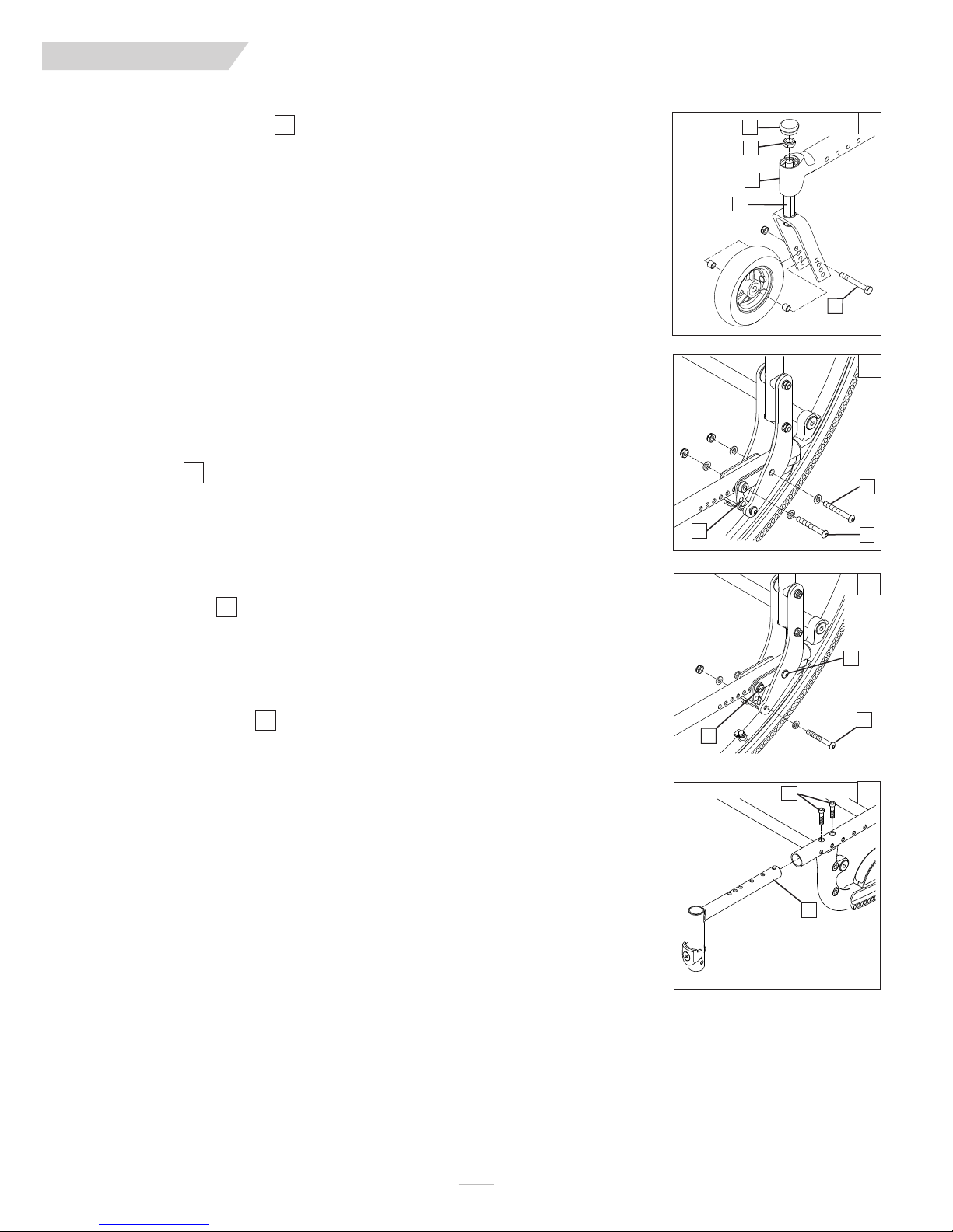
ENG LIS H
IX. DEALER SERVICE & ADJUSTMENT
W. CASTER/FORK ASSEMBLY
64
1. Installation
a. Remove dust cover (A) from caster housing. Pry cover off using a back and forth motion.
b. Caster assembly holds one nut (B) and one washer (immediately below the nut). Remove nut and
washer.
c. Insert caster stem (D) into caster housing (C) and place washer on stem.
d. Replace nut (B) on caster stem and tighten until all play is removed; then loosen approximately 1/8 turn,
allowing for free rotation.
e. Replace dust cover to caster housing.
2. Height Adjustment
a. Loosen and remove bolt (E).
b. Set axle at desired height using pre-set holes in the fork.
c. Replace and tighten bolt.
d. Repeat on other side.
NOTE–
The frame must be kept horizontal when height is adjusted. Refer to matrix in the ordering guide
for proper setting. Refer to Section S-7 for rear axle height adjustment.
X. FRAME DEPTH
1. Back adjustment
a. Remove the screws (F & H) from the back mounting plate (G) on both sides of the chair.
b. Slide the backrest along the seat rail to the same position on both sides.
c. Replace and tighten the screws (F & H) to lock in the position on both sides of chair.
IMPORTANT NOTE–
NOTE–
Use a torque setting of 120 in.-lbs. When setting-up back depth adjustment.
2. Back angle adjustment
a. Remove the screw(F) and loosen H) from the back mounting plate (G) on both sides of the chair.
b. Adjust the backrest to the same position on both sides, using one of the three adjustment holes
shown.
c. Tighten the screws (F & H) to lock in the position on both sides of chair.
65
The adjustment on each side of the chair should be exactly equal.
66
A
B
C
D
64
E
65
H
G
F
66
H
3. Hanger Receiver Adjustment
a. Loosen and remove both Socket head screws (I) from the seat rail.
b. Slide the hanger receiver (J) in the seat rail to the desired position.
c. Replace and tighten the socket head screws.
d. Repeat this process on the other side.
IMPORTANT NOTE–
IMPORTANT NOTE–
NOTE–
refer to matrix in the ordering guide for recommended location.
Use a torque setting of 120 in.-lbs. When setting-up hanger receiver.
These adjustments may also require re-positioning the carriage over the base frame,
The adjustment on each side should be exactly equal.
67
F
G
I
J
67
27
MK-100151 Rev. A
Page 28
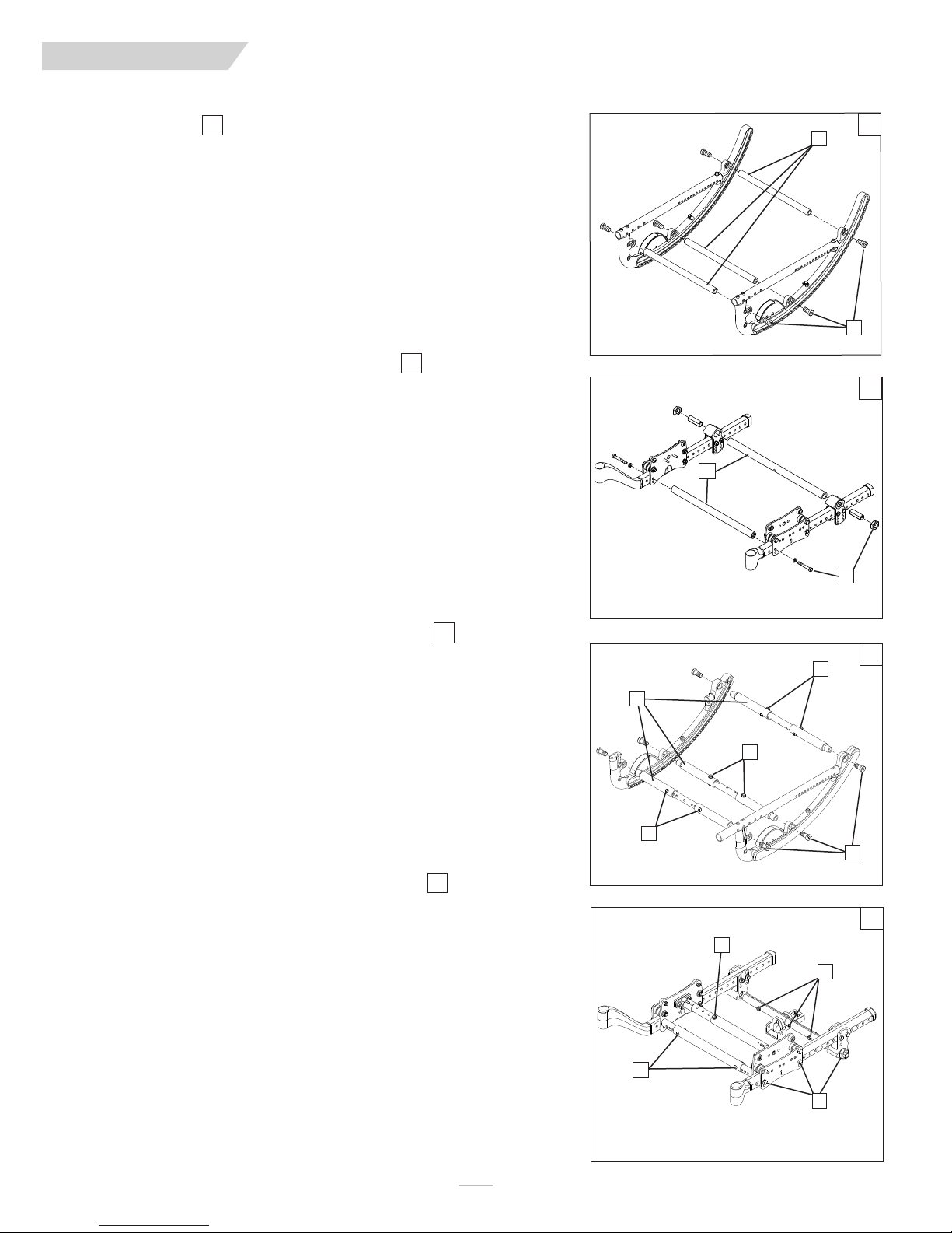
ENG LIS H
IX. DEALER SERVICE & ADJUSTMENT
Y. FRAME WIDTH
The frame of the IRIS is built to accommodate growth by using the growth kit components.
68
1) Fixed Strut Tube Width Adjustment (Rocker assembly)
a. Remove the bolts (A) from both ends of the strut tubes (B) for all strut tubes.
b. Replace with the appropriate length strut tubes
c. Tighten the bolts (A) at each end.
d. Repeat for each strut tube (B).
NOTE–
2) Fixed Strut Tube Width Adjustment (Roller assembly)
NOTE–
Use a torque setting of 200 in.-lbs. when tightening hardware (A).
69
a. Remove the bolts (C) from both ends of the strut tubes (D) for all strut tubes.
b. Replace with the appropriate length strut tubes
c. Tighten the bolts (C) at each end.
d. Repeat for each strut tube (D).
Use a torque setting of 200 in.-lbs. when tightening hardware (A).
B
68
A
69
D
3) Growable Strut Tube Width Adjustment (Rocker assembly)
a. Remove the hardware (E) from all three strut tubes (F) and adjust all three tubes an
equal distance.
b. When you are sure the width is equal for all three adjustable tubes, tighten the hardware
to a torque setting of 150 in-lbs after adjusting the strut tubes.
NOTE–
Use a torque setting of 200 in.-lbs. when tightening hardware (A).
4) Growable Strut Tube Width Adjustment (Roller assembly)
a. Remove the hardware (G), (H), and (I) from the strut tubes.
b. Adjust all three tubes an equal distance, and re-tighten the hardware to a torque setting
of 150 in-lbs after adjusting the strut tubes.
NOTE–
Use a torque setting of 200 in.-lbs. when tightening hardware (J)f
70
71
C
70
E
F
E
E
A
71
G
I
MK-100151 Rev. A
H
J
28
Page 29
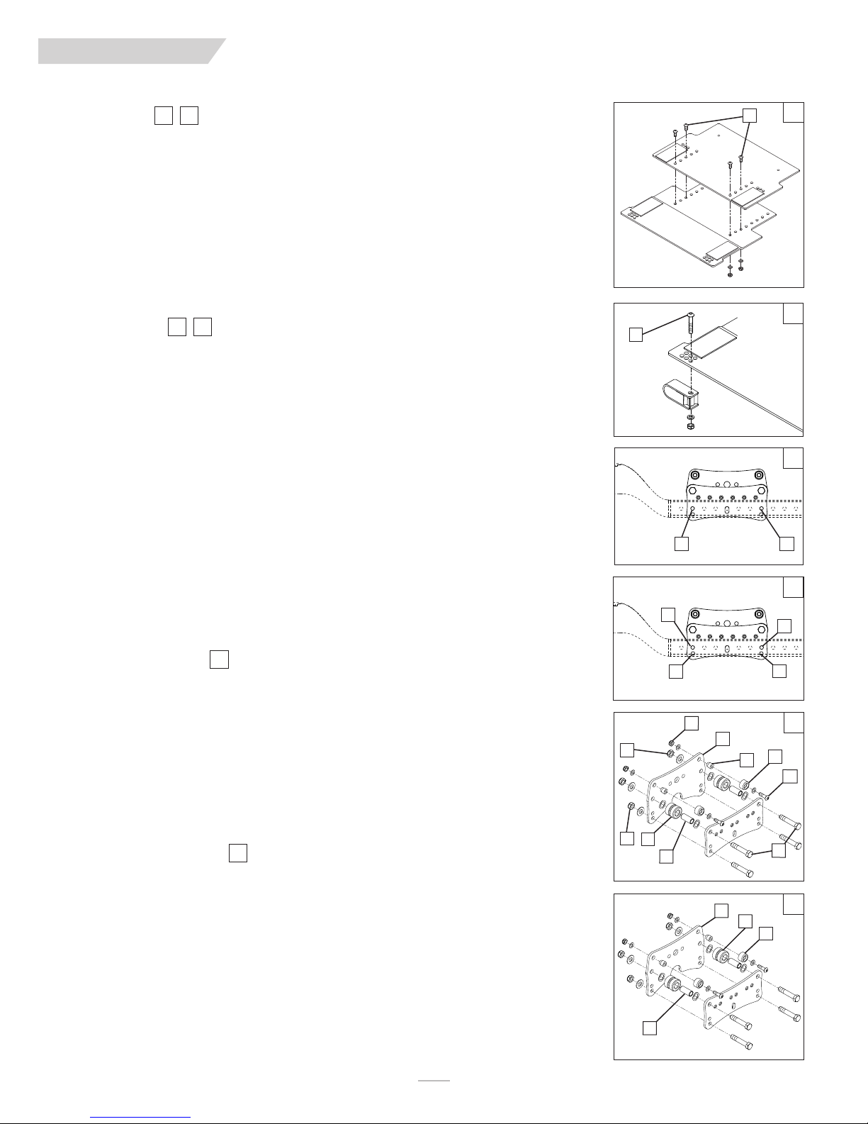
ENG LIS H
IX. DEALER SERVICE & ADJUSTMENT
Z. SEAT PAN
The seat pan of the IRIS is designed to accommodate depth adjustment.
7372
Depth adjustment
a. Loosen and remove all bolts (A).
b. Adjust the seat pan to the desired depth.
c. Replace and tighten all bolts.
NOTE– Use the holes that place the bolts as far away from each other as possible.
Width adjustment
a. Loosen and remove all bolts (B).
b. Adjust chair to the desired width.
c. Replace and tighten all bolts.
AA. CARRIAGE
The carriage of the IRIS can be adjusted to a preset the range of tilt.
7574
1. Adjustment
a. Loosen and remove bolts C & D.
b. Set the carriage at desired range setting using the proper holes.
c. Replace and tighten all bolts.
IMPORTANT NOTE–
NOTE–
Use a torque setting of 120 in.-lbs. When setting-up carriage.
The adjustment on each side of the chair should be exactly equal.
2. Range and setting– 55°
a. -5° to 50°– use holes E & H
b. 0° to 55°– use holes E & G
c. 5° to 60°– use holes F & G
3. Range and setting– 40°
a. -5° to 35°– use holes E & H
b. 0° to 40°– use holes E & G
c. 5° to 45°– use holes F & G
NOTE–
It is highly recommended to replace both rollers within each carriage assembly at the same time.
Do not use lubricants anywhere on the assembly.
72
A
73
B
74
C
D
75
E
G
4. Top Roller Replacement
a. Loosen both plunger pin bracket nuts.
b. Loosen and remove both lower roller nuts (I), chassis fastener nut (J), and base strut bolts (K) on both
sides. Remove base strut.
c. Slide the inner carriage plate (L) off the fasteners, towards the center of the chair.
d. Loosen and remove both sides of the roller hardware (M).
e. Remove old top rollers (N) from the upper roller shafts (O) and replace with new top rollers (P).
f. Reinstall the upper roller shafts (O) onto the inner carriage plate (L), installing roller hardware (M).
g. Reinstall carriage plate (L) onto the frame assembly. Replace and tighten the nuts (I, J) and strut bolts (K).
h. Ensure that the plunger pin is centered and engaged into a rocker hole and pin bracket nuts are tight.
i. Repeat on the other side of chair as necessary.
5. Bottom Roller Replacement
a. Loosen both plunger pin bracket nuts.
b. Loosen and remove both lower roller nuts (I), chassis fastener nut (J), and base strut bolts (K).
c. Slide the inner carriage plate (L) off the fasteners, towards the center of the chair.
d. Remove old bottom rollers (Q) from the roller bushings (R) and replace with new bottom rollers(S).
e. Reinstall carriage plate (L) to the frame assembly. Replace and tighten the nuts (I, J) and bolts (K).
f. Ensure that the plunger pin is centered into a rocker hole and tighten plunger pin bracket nuts.
g. Repeat on the other side of chair as necessary.
NOTE– Use a torque setting of 150 in.-lbs. when tightening bottom roller hardware (J)(K).
76
77
F
M
I
J
Q
R
R
L
L
H
76
N
O
M
K
77
S
P
29
MK-100151 Rev. A
Page 30
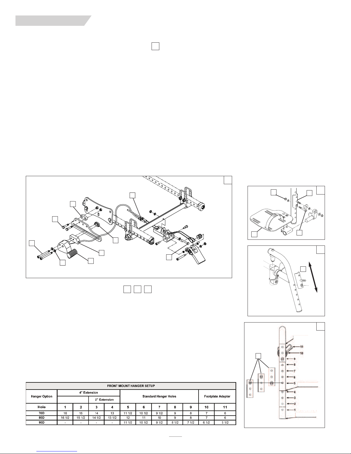
ENG LIS H
IX. DEALER SERVICE & ADJUSTMENT
BB. ATTENDANT WHEEL LOCK INSTALLATION
1. Remove wheels from chair.
2. Attach Mount bracket/cable assembly to axle strut tube using 1/4" x 1-3/4" bolt (item 1) with nut and washers.
3. If push-to-lock wheel locks are already installed, remove the push-to-lock assemblies by removing the M6 bolts (item 2) and adjustment nuts (item 3),
leaving the slide plates mounted on the chair, and go to step 5. If there are no wheel locks mounted already, proceed with step 4.
4. Attach Wheel Lock Slide Plates to Roller Assembly on each side of the chair using 1/4" hex bolts (item 4) and Mounting Block (item 5). If axle of rear
wheel is above the base frame tube, orient the slide plates upward. If the axle of the rear wheel is below the base frame tube, orient the plates down-
ward. Plate may be flipped forward or reversed as needed for different wheel sizes.
5. Attach the left and right Remote Lock Assemblies (item 6) to the slide plates using the Attendant Wheel Lock Spacer Blocks (item 7), M6 x 60 screws
(item 2), lock washers (item 8), and Wheel Lock Adjustment Nuts (item 3). The adjustment nuts marked “R” and “L” are to be mounted to the right and
left side of the chair respectively. The smaller protruding oval shape on the nuts should slide inside of the slot in the slide plate. Do not tighten bolts.
Slide the Remote Lock Assemblies as far forward as they will go.
6. Re-install wheels and slide the Remote Lock Assemblies rearward until the friction block of the remote lock is approximately 1/4" (6mm) away from the
tire when unlocked. If the lock cannot be adjusted to this position, you will need to adjust the position of the slide plate until it can be adjusted as stat-
ed. Once remote locks are properly positioned, tighten bolts.
7. Attach cables to Remote Lock Assemblies by sliding the stud at the end of the cable into the slot in the Remote Lock Assembly. Pull back on the cable
sheath and slide the end of the cable sheath into the pocket on the Attendant Wheel Lock Spacer Block (item 3) as shown. Be sure that the cables are
routed away from all moving parts. Attach the cables into place on the chair with zip-ties provided.
8. Adjust the cable adjustment screws (item 9) as necessary to ensure that the wheel locks can get to their fully extended position when the pedal is
engaged. Position of the Remote Lock Assembly may need to be fine tuned to optimize the force needed to engage the pedal, depending on tire type. If
excessive force is needed to engage the pedal, cable life may be reduced. Once proper adjustment is attained, lock cable adjustment screw in position by
tightening jam nuts against mounting block.
78
78
9
5
B
A
79
4
2
8
6
CC. FOOTPLATE ADAPTER BRACKET
The footplate adapter bracket(A) can be installed by the dealer. The main purpose of this part is to allow for
height adjustment while using front mount footplates on a quick release hanger. The plate can be reversed
which adds to it’s range of adjustment.
3
7
818079
1
1. Footplate Height Adjustment
a. Remove the hardware (B, C) and remove the footplate(D) and adapter plate assembly.
b. Move the footplate(D) and assembly up or down to the desired position, using the “Front mount hang-
er setup” table, and (figure 32) as reference.
c. Re-insert and tighten the hardware (B, C) to a torque of (96in-lbs)
d. Repeat the process for the other hanger and footplate.
NOTE–
In most cases you will want to make sure the footplates are adjusted so that the height is the same on
both sides
D
C
80
A
81
ADAPTER
A
2” EXTENSION
MK-100151 Rev. A
4” EXTENSION
30
Page 31

ENG LIS H
ENG LIS H
IX. DEALER SERVICE & ADJUSTMENT
DD. LAP BELT INSTRUCTIONS
NOTE– Lap belts are fitted as positional aids, and are not suitable as transportation restraints.
85848382
Positioning Belt Kit
The positioning belt kit contains: one positioning belt (A), three tri glide buckles (B), two cable ties (C)
1. To assemble the positioning belt, take the positioning belt strap and thread through the tri-glide.
Repeat on both ends of positioning belt.
2. To fit the positioning belt to the chair, take the positioning belt strap and wrap around the back post.
3. Thread the positioning belt back through the tri-glide to form a loop around the back post. Thread
positioning strap through tri-glide as shown.
4. To secure the positioning belt to the chair. Take one of the cable ties supplied and thread through the
positioning belt strap. Then wrap around the frame and fasten together. DO NOT over tighten posi-
tioning belt. Repeat steps 2-4 with both ends of positioning belt.
5. To adjust the positioning belt use the tri-glide buckles and the fastening buckle.
6. The positioning belt should be adjusted so the fastening buckle is situated in the middle of the stom-
ach.
7. The positioning belt should be adjusted so a hand can be placed between the user and the belt.
WARNING
The positioning belt must only be fitted by an approved Sunrise Medical dealer/agent. The positioning belt
should only be adjusted by a professional, or a Sunrise Medical approved dealer/agent. The positioning belt
must be checked on a daily basis to ensure it is adjusted correctly (see step 6) and is free from any obstruction or adverse wear. Sunrise Medical does not encourage the transportation of any person in a vehicle using
this positioning belt as a method of restraint. Please see Sunrise Medical transit booklet for further advice on
transportation.
Lap Belt Maintenance
Check lap belt and securing components at regular intervals for any sign of frays or damage. Replace if necessary.
NOTE–
The lap belt should be adjusted to suit the end user as detailed above. Sunrise Medical recommends that
the length and fit of the belt be checked on a regular basis to reduce the risk of the end user inadvertently re-adjusting the belt to an excessive length.
C
A
82
B
83
84
85
EE. CHECK-OUT
Once the wheelchair is assembled and adjusted, it should roll smoothly and easily. All accessories should also
perform smoothly. If you have any problems, follow these procedures:
1. Review assembly and adjustment sections to make sure the chair was properly prepared.
2. Review troubleshooting guide.
3. If your problem persists, contact your authorized supplier. If you still have a problem after contacting
your authorized supplier, contact Sunrise customer service. See the introduction page for details on
how to contact your authorized supplier or Sunrise customer service.
31
MK-100151 Rev. A
Page 32

ENG LIS H
X. SUNRISE LIMITED WARRANTY
A. FOR LIFETIME
Frame and cross-brace (if applicable) warranty:
1. Although the anticipated useful service time of this wheelchair is five
years, Sunrise guarantees the frame and cross brace against defects
in material and workmanship for life or for as long as the original
purchaser owns the chair.
2. This warranty does not apply if:
a. The chair is subject to abuse
b. The chair is not maintained as recommended in the owner’s
manual
c. The chair is transferred to a different person from the original
owner
B. FOR ONE (1) YEAR
We warrant all Sunrise-made parts and components of this wheelchair
against defects in materials and workmanship for one year from the date of
first consumer purchase.
C. LIMITATIONS
1. We do not warrant:
a. Tires and tubes, upholstery, pads and push-handle grips.
b. Damage from neglect, accident, misuse, or from improper instal-
lation or repair.
c. Products modified without Sunrise Medicals express written
consent.
d. Damage from exceeding the weight limit.
2. This warranty is VOID if the original chair serial number tag is
removed or altered.
3. This warranty applies in the USA only. Check with your supplier to
find out if international warranties apply.
4. This warranty is not transferable and only applies to the first consumer purchase of this wheelchair through an authorized Sunrise
Medical dealer.
E. WHAT YOU MUST DO
1. Obtain from us, while this warranty is in effect, prior approval for
return or repair of covered parts.
2. Return the wheelchair or part(s), freight pre-paid, to Sunrise Mobility
Products Division at: 2842 Business Park Avenue, Fresno, CA 93727-
1328.
3. Pay the cost of labor to repair, remove or install parts.
F. NOTICE TO CONSUMER
1. If allowed by law, this warranty is in place of any other
warranty (written or oral, express or implied, including a warranty of
merchantability, or fitness for a particular
purpose).
2. This warranty gives you certain legal rights. You may also have other
rights that vary from state to state.
G. ADDITIONAL WARRANTY INFORMATION
For goods provided by Sunrise Medical Pty Ltd in Australia, our goods
come with a guarantee by Sunrise that cannot be excluded under the
Australian Consumer Law. You are entitled to a replacement or refund for
a major failure and for compensation for any other reasonably forseeable
loss or damage. You are also entitled to have the goods repaired or
replaced if the goods fail to be of acceptable quality and the failure does
not amount to a major failure. The benefits to you given by this warranty
are in addition to your other rights and remedies under a law in relation to
the goods to which the warranty relates.
D. WHAT WE WILL DO
Our sole liability is to repair or replace covered parts. This is the exclusive
remedy for consequential damages.
Record your serial number here for future reference:
___________________________________________
MK-100151 Rev. A
32
Page 33

SECT ION
ENGLIS H
IRIS
*
*
*
Supplier:
User:
Quickie
Zippie
with transit option
®
IRIS
®
IRIS SE
This manual must be given to the user of this wheelchair.
Before using this wheelchair read this entire manual and save for
future reference.
*
Quickie®IRIS SE
*
without transit option
Quickie®IRIS Quickie®IRIS SE
®
Zippie
Distribuidor:
Pasajero:
Cada una de las sillas se envía con un manual de instrucciones en inglés. El manual en español o
francés está disponible en formato PDF en nuestra página en Internet: www.SunriseMedical.com.
Ingrese a la página del producto específico para descargar el manual, o comuníquese con el
proveedor autorizado de Sunrise Medical.
IRIS SE
Este manual debe ser entregado al pasajero de esta silla de
ruedas.
Antes de usar esta silla de ruedas, lea este manual en su totalidad y guárdelo para futura referencia.
O w n e r ’s M a n u a l
M a n u a l d e I n s t r u c c i o n e s
Page 34

ESP AÑ OL
SUNRISE MEDICAL ESCUCHA
Gracias por elegir una silla de ruedas con inclinación en el espacio Quickie/Zippie
IRIS. Nos gustaría recibir sus preguntas o comentarios acerca de este manual, de
la seguridad y fiabilidad de su silla, o del servicio que ha recibido de su distribuidor Sunrise. No dude en escribirnos o llamarnos al domicilio y teléfono que
aparecen a continuación:
SUNRISE MEDICAL
Departamento de Servicio al Cliente
2842 Business Park Avenue
Fresno, CA 93727
1 (800) 333-4000
No olvide regresar su tarjeta de garantía e informarnos si cambia de domicilio.
Esto nos permitirá mantenerlo al tanto con información acerca de la seguridad,
productos nuevos y opciones para mejorar el uso y disfrutar de la silla de ruedas.
Si ha perdido su tarjeta de garantía, llame o escriba y con gusto le enviaremos una
nueva.
I. INTRODUCCIÓN
PARA CONTESTAR SUS PREGUNTAS
Su distribuidor autorizado conoce bien su silla de ruedas y puede contestar la
mayoría de sus preguntas acerca de la seguridad, uso y mantenimiento de la silla.
Como información de referencia para el futuro, escriba los siguientes datos:
Distribuidor:
______________________________________________________________________
Dirección:_________________________________________________________________________
______________________________________________________________________________________
Teléfono: __________________________________________________________________________
Núm. Serie:_______________________ Fecha de compra: ________________________
Información adicional que debería conocer:
Ningún componente de esta silla se realizó con látex de caucho natural.
MK-100151 Rev. A
34
Page 35

ESP AÑ OL
II. ÍNDICE
I. INTRODUCCIÓN.........................................................................34
II. ÍNDICE .............................................................................................35
III. SU SILLA Y SUS PARTES .............................................................36
IV. AVISO: LEA ESTE MANUAL ANTES DE USAR EL .................
PRODUCTO.....................................
V. ADVERTENCIAS GENERALES...................................................37
A.Límites de peso.........................................................................37
B. Uso previsto ..............................................................................37
C. Ayudantes y cuidadores.........................................................37
D. Accesorios
E. Conozca su silla ........................................................................37
F. Reduzca el riesgo de un accidente.......................................37
G.Lista de verificación de seguridad.........................................37
H.Cambios y ajustes ....................................................................37
I. Condiciones ambientales........................................................38
J. Terreno .......................................................................................38
K.Uso en la calle...........................................................................38
L. Seguridad de vehículos motorizados....................................38
M.Cuando necesite ayuda ...........................................................39
VI. ADVERTENCIAS DE SEGURIDAD: CAÍDAS Y .......................
VOLCADURAS...............................................................................39
A.Centro de equilibrio ................................................................39
B. Al vestirse o cambiarse de ropa...........................................39
C.Obstáculos .................................................................................39
D. Elevación de la rueda pivotante delantera .........................40
E. Al estirarse o inclinarse..........................................................40
F. Cómo moverse hacia atrás .....................................................40
G.Escaleras mecánicas .................................................................40
H. Rampas, pendientes y laderas ...............................................40
I. Cambios......................................................................................41
J. Aceras y escalones sencillos....................................................42
K.Para subir a una acera o escalón sencillo...........................42
L. Para bajar de una acera o escalón sencillo ........................42
M.Escaleras .....................................................................................43
N. Para subir escaleras................................................................43
O. Para bajar escaleras.................................................................43
P. Uso de la inclinación................................................................43
VII. ADVERTENCIAS: COMPONENTES Y OPCIONES.............44
A.Tubos contra volcaduras.........................................................44
B. Reposabrazos............................................................................44
C.Asideros de empuje .................................................................44
D. Manija de la silla de paseo......................................................44
E. Cojines........................................................................................44
F. Sujetadores ................................................................................44
G. Reposapiés.................................................................................44
H Llantas neumáticas ...................................................................44
I. Cinturones de posicionamiento............................................45
J. Eje de liberación rápida...........................................................45
K.Ejes traseros..............................................................................45
L. Seguros de las ruedas traseras..............................................45
M. Sistemas de asiento modificados .........................................45
N. Bandeja para ventilación y batería.......................................45
O.Gancho de accesorios.............................................................45
VIII. USO Y MANTENIMIENTO DEL PROPIETARIO ................46
A. Introducción ............................................................................46
B. Consejos fundamentales para el mantenimiento..............46
C.Tabla de mantenimiento..........................................................46
D.Limpieza......................................................................................46
E. Tabla de solución de problemas ...........................................47
F. Para montar y quitar las ruedas traseras.............................47
..............................................36
G.Instalación del cojín .................................................................47
H. Seguros de las ruedas ............................................................48
I. Seguro del cubo........................................................................48
J. Tubos traseros contra volcaduras..........................................48
K. Reposabrazos de poste doble...............................................49
L. Reposabrazos de altura ajustable .........................................49
M.Reposabrazos elevables ajustables con bloqueo...............49
N.Reposabrazos levadizos ..........................................................50
O.Reposapiés/Sostenes giratorios.............................................50
P. Reposapiés elevables de uso pesado ...................................50
Q.Reposapiernas articulado .......................................................50
R. Reposapiernas elevable ...........................................................51
S. Mecanismo con inclinación en el espacio...........................51
T. Extensión de la manija de la silla de paseo ........................52
U.Respaldo reclinable..................................................................52
V. Manija de la silla de paseo con respaldo de una sola pieza .52
W.Plegado del Respaldo De Una Sola Pieza Para Transporte..52
X.Revisión.......................................................................................52
IX.
AJUSTE Y SERVICIO DEL DISTRIBUIDOR ............................53
A.Información de servicio del distribuidor ............................53
B. Consejos fundamentales para el mantenimiento..............53
C.Limpieza ......................................................................................53
D.Eje trasero..................................................................................53
E. Ajuste del seguro del cubo ....................................................54
F. Seguros de las ruedas..............................................................54
G.Receptáculo del reposabrazos de un solo poste..............54
H.Reposabrazos elevables ajustables con bloqueo...............55
I. Reposabrazos levadizos elevables con bloqueo................55
J. Ajuste giratorio de altura.......................................................56
K.Reposapiés elevables de uso pesado ...................................56
L. Reposapiernas articulado .......................................................56
M.Reposapiernas elevable ...........................................................56
N.Reposapiés Contracture ........................................................57
O.Mecanismo con inclinación en el espacio...........................57
P. Respaldo Estándar....................................................................58
Q.Respaldo de una Sola Pieza ...................................................58
R.Respaldo Dinámico de una Sola Pieza .................................59
S. Respaldo Dinámico de una Sola Pieza (Reemplazo de
Elastomero)................................................................................60
T. Soporte Colgante Para Ventilador........................................60
U.Manija Fija de la Silla de Paseo..............................................60
V. Manija Ajustable de la Silla de Paseo (Respaldo de una
sola pieza)...................................................................................60
W.Conjunto de Ruedas Pivotantes/horquilla..........................61
X.Profundidad del Armazón.......................................................61
Y. Ancho del Armazón.................................................................62
Z.Recipiente del Asiento ............................................................63
AA.Chassis......................................................................................63
BB. Instalación de seguros de ruedas para el ayudante .......64
CC.Abrazadera adaptadora del reposapiés............................65
DD.Instrucciones del cinturón subabdominal ........................66
EE.Revisión......................................................................................66
X. GARANTÍA LIMITADA DE SUNRISE ......................................67
35
MK-100151 Rev. A
Page 36

ESP AÑ OL
III. SU SILLA Y SUS PARTES
QUICKIE IRIS
4
5
1. Apoyacabeza
1
2
2. Manija de empuje/Bastón del respaldo
3. Reposabrazos
4. Soporte del reposapiés
5. Estribo
6. Chasis
3
7. Horquilla de la rueda pivotante
8. Llanta de la rueda pivotante
9. Seguro de las ruedas
10. Rueda trasera de 30,48 cm (12 pulg.)
13
11. Contra volcaduras
12. Recipiente ajustable del asiento
13. Palanca de liberación del mecanismo con
12
inclinación en el espacio
11
6
NOTA– No todas las opciones están disponibles
en ambas sillas de ruedas IRIS Quickie y
Zippie. Consulte el formulario de pedidos para obtener información sobre las
opciones específicas disponibles.
7
8
IV. AVISO: LEA ESTE MANUAL ANTES DE USAR EL PRODUCTO
A. SELECCIONE LA MEJOR SILLA Y LAS OPCIONES DE
SEGURIDAD
Sunrise ofrece una variedad de estilos diferentes de sillas de ruedas para
satisfacer sus necesidades. Este producto fue diseñado para que solo lo use
una persona. La selección final del tipo, las opciones y los ajustes de la silla
de ruedas es solamente suya y de su profesional de la salud. La selección de
la mejor silla y de los mejores ajustes de seguridad para usted depende de
factores como:
1. Su discapacidad, fortaleza, equilibrio y coordinación.
2. Los tipos de riesgos que enfrentará en el uso diario (lugar donde
vive y trabaja, y los otros sitios donde es probable que use su silla).
3. La necesidad de opciones que mejorarán su posición, seguridad y
comodidad (tales como los tubos contra volcaduras, los cinturones
posicionadores o los sistemas especiales de transporte.)
B. LEA ESTE MANUAL CON FRECUENCIA
Antes de usar esta silla, usted y cada persona que lo asista deben leer este
manual por completo y asegurarse de seguir todas las instrucciones. Repase
con frecuencia las advertencias, hasta que las aprenda de memoria.
10
9
C. ADVERTENCIAS
La palabra “
que pueden provocarle a usted o a otras personas lesiones graves o incluso la muerte. Las “Advertencias” se dividen en tres secciones principales:
3. VII– ADVERTENCIAS - COMPONENTES Y OPCIONES
NOTA–
ADVERTENCIA
1. V– ADVERTENCIAS GENERALES
Here you will find a safety checklist and a summary of risks you
need to be aware of before you ride this chair.
2. VI– ADVERTENCIAS DE SEGURIDAD: CAÍDAS Y VOLCADURAS
Aquí aprenderá las prácticas para el uso seguro de su silla y para
evitar una caída o una volcadura mientras realiza sus actividades
diarias en la silla.
Aquí aprenderá acerca de los componentes de su silla y las opciones
que tiene para su seguridad. Consulte a su distribuidor autorizado y
a su profesional de la salud para ayudarle a seleccionar la mejor configuración y opciones para un uso seguro.
Donde corresponda, también encontrará “Advertencias” en otras
secciones de este manual. Obedezca todas las advertencias de
esta sección. Si no lo hace, puede ocurrir una caída, volcadura o
pérdida del control y provocar lesiones severas al pasajero o a
otras personas
” se refiere a un peligro o una práctica insegura
MK-100151 Rev. A
36
Page 37

ESP AÑ OL
V. ADVERTENCIAS GENERALES
A. LÍMITES DE PESO
ADVERTENCIA
NUNCA
capacidad de peso proporcionada por el fabricante es para el peso combinado de un pasajero y los elementos acarreados usando el almacenamiento a
bordo. Si sobrepasa el límite de peso, puede ocurrir daño a su silla, una caída,
volcadura o pérdida del control y provocar lesiones severas al pasajero o a
otras personas.
Capacidades de peso
Quickie IRIS - 113 kg/(250 libras)..
Zippie IRIS - 75 kg/(165 libras).
Quickie IRIS HD - 159 kg/(350 libras).
B. USO PREVISTO
Las sillas de ruedas de las series IRIS Quickie y Zippie fueron diseñadas
para proporcionar movilidad a personas con una posición limitada al sentarse.
sobrepase el límite de peso especificado por Sunrise Medical. La
ADVERTENCIA
NO
use este dispositivo para otros fines que no hayan sido los previstos
por el fabricante.
1. La silla de ruedas no está diseñada para ejercitarse en el levantamiento de pesas y no es segura para usarla como asiento mientras
se practica esa actividad. Levantar pesas en una silla de ruedas cambia sustancialmente la estabilidad de la silla y puede provocar volcaduras.
NO
2.
se pare sobre el armazón de la silla de ruedas.
NUNCA
3.
escalera.
4. Esta silla está diseñada para un único pasajero.
5. Las modificaciones no autorizadas o el uso de partes o accesorios
no aprobados o suministrados por Sunrise Medical podrían cambiar
la estructura de la silla. Esto anulará la garantía y puede crear un
riesgo de seguridad. Si se ignora esta advertencia, se puede dañar la
silla y producir una grave lesión potencial de la persona que usa la
silla con fines para los que no fue diseñada.
permita que nadie se pare sobre la silla ni la use como
C. AYUDANTES Y CUIDADORES
ADVERTENCIA
Antes de ayudar al pasajero de la silla de ruedas, asegúrese de leer las
advertencias contenidas en este manual y de seguir todas las instrucciones
que se apliquen. Tenga en cuenta que después de consultar a un profesional
de la salud, deberá aprender una mecánica corporal segura y probada para
usar y crear los métodos de asistencia más adecuados para su capacidad.
D. ACCESORIOS
ADVERTENCIA
Las modificaciones no autorizadas o el uso de partes o accesorios no
aprobados o suministrados por Sunrise Medical podrían cambiar la estructura de la silla. Esto anulará la garantía y puede crear un riesgo de seguridad.
Podrían producirse algunos problemas, entre otros:
1. Ruedas o llantas incorrectas que hacen que el pasajero corra el riesgo
de caídas o volcaduras.
2. Agregar un componente al armazón, cambiar la integridad estructural
de la silla.
3. Realizar cualquier modificación o desarmar la silla de ruedas puede
crear una situación insegura en la que el pasajero o el ayudante corren riesgos
E. CONOZCA SU SILLA
ADVERTENCIA
Cada silla de ruedas es diferente. Tómese su tiempo para conocer las características de esta silla antes de empezar a usarla. Empiece lentamente, con
impulsos leves, suaves. Si está acostumbrado a una silla diferente, podría
aplicar demasiada fuerza y volcarse. Si aplica demasiada fuerza, podría
provocar daño a su silla, una caída, volcadura o pérdida del control y provocar lesiones severas al pasajero o a otras personas.
F. REDUZCA EL RIESGO DE UN ACCIDENTE
ADVERTENCIA
ANTES
1.
2. Practique doblarse, estirarse y cambiarse hasta que conozca el límite
3. Tenga en cuenta que debe desarrollar sus propios métodos para un
4.
5. Conozca las áreas donde planea usar su silla. Tenga cuidado con los
6. Use los tubos contra volcaduras a menos que sea un pasajero hábil
Si hace caso omiso de estas advertencias, pueden ocurrir daños a su silla, una
caída, volcadura o pérdida del control y provocar lesiones severas al pasajero
o a otras personas.
de que use esta silla, su profesional médico debe instruirlo
en el uso seguro de ella.
de su habilidad. Haga que alguien le ayude hasta que conozca lo que
puede provocar una caída o volcadura y cómo evitarlas.
uso seguro y que sean los mejores para su nivel de funcionalidad y
habilidad.
NUNCA
esté seguro de que puede hacerla sin riesgos.
peligros y aprenda a evitarlos.
en esta silla y que esté seguro de que no tiene riesgo de volcarse.
intente una nueva maniobra por sí mismo a menos que
G. LISTA DE VERIFICACIÓN DE SEGURIDAD
ADVERTENCIA
Antes de cada uso de su silla:
1. Asegúrese de que su silla se desplace con facilidad y de que todas las
partes funcionen bien. Compruebe si hay algún ruido, vibración o
variación en su uso corriente. (Pueden indicar baja presión en las
llantas, sujetadores sueltos o daños en su silla.)
2. Solucione cualquier problema. Su distribuidor autorizado le puede
ayudar a encontrar y corregir el problema.
3. Verifique que ambos ejes traseros de liberación rápida estén asegurados. Cuando están asegurados, el botón del eje “saldrá” por completo. Si no lo están, la rueda podría salirse y provocar una caída.
Si hace caso omiso de estas advertencias, pueden ocurrir daños a su silla, una
caída, volcadura o pérdida del control y provocar lesiones severas al pasajero
o a otras personas.
H. CAMBIOS Y AJUSTES
ADVERTENCIA
1. Consulte a su profesional de la salud y haga que adapte los componentes del asiento en cualquier momento en que sea necesario
hacer un cambio o ajustes.
2. Las modificaciones no autorizadas o el uso de partes no aprobadas
o suministradas por Sunrise podrían cambiar la estructura de la silla.
Esto anulará la garantía y puede crear un riesgo de seguridad.
Si hace caso omiso de estas advertencias, pueden ocurrir daños a su silla, una
caída, volcadura o pérdida del control y provocar lesiones severas al pasajero
o a otras personas.
37
MK-100151 Rev. A
Page 38

ESP AÑ OL
I. CONDICIONES AMBIENTALES
ADVERTENCIA
1. Tenga más cuidado si debe usar su silla sobre
una superficie húmeda o resbalosa. Si tiene
dudas, pida ayuda.
2. El contacto con el agua o el exceso de humedad puede provocar
que su silla se oxide o corroa. Evite todas las situaciones climáticas
extremas si es posible.
a. No use su silla para bañarse, en la piscina o cualquier otra masa
de agua. Los tubos y piezas de la silla no son herméticos y
pueden oxidarse o corroerse desde adentro.
b. Evite el exceso de humedad (por ejemplo, no deje su silla en un
baño húmedo mientras se baña).
c. Seque la silla tan pronto como pueda en caso de que se moje o si
usa agua para limpiarla.
J. TERRENO
V. ADVERTENCIAS GENERALES
ADVERTENCIA
Si su silla NOestá equipada con la opción de tránsito:
NUNCA
1.
encuentre en un vehículo en movimiento.
2. En caso de accidente o parada súbita, el pasajero podría ser lanzado
de la silla. Los cinturones de la silla de ruedas no prevendrán esto, y
los cinturones y las correas pueden causar lesiones adicionales.
NUNCA
3.
Podría moverse e interferir con el conductor.
4. Asegure
No
5.
de vehículos de motor. El armazón o los componentes pueden haber
cambiado debido a un accidente. Esos elementos podrían ser, entre
otros: componentes doblados, sueltos o rotos que sufrieron un
impacto.
permita que alguien se siente en esta silla cuando se
SIEMPRE
a.
b. Asegure
to apropiados del vehículo de motor.
use ninguna silla que se haya visto involucrada en un accidente
cambie al usuario a un asiento de vehículo aprobado.
SIEMPRE
transporte esta silla en el asiento delantero de un vehículo.
SIEMPRE
al pasajero con los restrictores de movimien-
esta silla de tal manera que no se mueva o ruede.
1. Basándose en las pruebas del (ANSI)/(RESNA), Sunrise Medical
ADVERTENCIA
recomienda el uso de una rueda pivotante con un diámetro mínimo
de 12,7 cm (5 pulg.) si la silla de ruedas superará regularmente
obstáculos de hasta 1,27 cm (½ pulg.)
2. Su silla está diseñada para usarse sobre una superficie firme y nivelada, tal como el concreto y el asfalto, y pisos y alfombras en interiores.
3. No use su silla en la arena, en la tierra suelta o en un terreno rocoso.
4. ISi usa la silla en un terreno que sea más irregular que lo descrito
anteriormente, existe el peligro de que los tornillos y los pernos se
aflojen antes de lo previsto, y de que el daño ocasionado en las
ruedas o en los ejes exponga al pasajero al riesgo de una caída, una
volcadura o la pérdida de control.
K. USO EN LA CALLE
ADVERTENCIA
1. Este producto no fue diseñado para ser usado en la calle.
2. Siempre que sea posible, evite las calles.
3. Obedezca y cumpla con todas las leyes que se aplican a los peatones
y a las sendas para peatones.
4. Esté alerta del peligro que representan los vehículos automotores
en los estacionamientos, o si debe cruzar una calle.
Si hace caso omiso de estas advertencias, pueden ocurrir daños a su silla, una
caída, volcadura o pérdida del control y provocar lesiones severas al pasajero
o a otras personas.
A
Horquilla de tránsito delantera
Busque este símbolo en su silla de ruedas. Indica los puntos
de fijación de la silla de ruedas que cumplen con la norma
ANSI/RESNA (1998) V.1 - Section 19 and/or ANSI/RESNA
(2012) V.4 WC-19. Para obtener más información relacionada
con tránsito, consulte el “Complemento Fijación de Tránsito”
incluido con su silla.
1
Horquilla de tránsito trasera
2
B
L. SEGURIDAD EN VEHÍCULOS MOTORIZADOS
Siempre que sea posible, el pasajero se debe trasladar al asiento del vehículo
del Fabricante del Equipo Original (OEM) y utilizar el sistema de restrictor
de movimiento del fabricante del equipo original instalado en el vehículo.
Sunrise Medical proporciona un Sistema de Sujetadores de Sillas de Ruedas
y Restrictores de Movimiento del Ocupante WC-19 que también se llama
Opción de tránsito. Para identificar si la silla ha sido fabricada con la
Opción de tránsito ya instalada, busque cuatro puntos de fijación. Dos puntos delanteros y dos puntos traseros. Estos puntos se reconocen por la calcomanía de puntos de fijación que se encuentra sobre los puntos de
fijación o cerca de ellos. Si su silla de ruedas está equipada con la Opción
de tránsito, repase el complemento Fijación de Tránsito que se entregó con
la silla de ruedas para obtener instrucciones e información adicionales.
Puede solicitarle una copia a su proveedor autorizado o a Sunrise Medical
si no lo tiene.
MK-100151 Rev. A
1 2
38
Page 39

ESP AÑ OL
V. ADVERTENCIAS GENERALES
M. CUANDO NECESITE AYUDA
ADVERTENCIA
Para el pasajero:
todas las advertencias e instrucciones que se apliquen.
Para los ayudantes:
1. Trabaje en conjunto con el doctor, la enfermera o el terapeuta del
pasajero de la silla para aprender los métodos seguros y mejor adaptados a sus capacidades y las del pasajero.
2. Infórmele al pasajero lo que planea hacer y explíquele lo que espera
que haga. Esto tranquilizará al pasajero y reducirá el riesgo de accidente.
3. Asegúrese de que la silla tenga asideros de empuje. Ofrecen puntos
seguros para que usted sostenga la parte posterior de la silla para
evitar una caída o volcadura. Revise que los asideros de empuje no
giren ni se salgan.
Asegúrese de que cada persona que le ayude, lea y siga
VI. ADVERTENCIAS DE SEGURIDAD: CAÍDAS Y VOLCADURAS
A. CENTRO DE EQUILIBRIO
ADVERTENCIA
El punto donde esta silla se volcará hacia delante, atrás o lateralmente
depende de su centro de gravedad y estabilidad. La manera como esté ajustada su silla, las opciones que seleccionó y los cambios que haga pueden influir
en el riesgo de una caída o volcadura.
Los ajustes más importantes son:
1.
a. La posición de las ruedas traseras. Cuanto más mueva las
ruedas traseras hacia adelante, más probable será que su silla se
vuelque hacia atrás..
b. La posición del chasis.
El centro de equilibrio también se ve afectado por:
2.
a. Un cambio en la configuración de su silla, lo que incluye:
• La altura y el ángulo del asiento.
• El ángulo del respaldo.
b. Los cambios de posición del cuerpo, de postura o de distribu-
ción del peso.
c. Uso de su silla en una rampa o plano inclinado.
d. El uso de una mochila u otras opciones y la ubicación y cantidad
del peso agregado puede cambiar equilibrio de la silla.
Para reducir el riesgo de un accidente::
3.
a. Consulte a su doctor, enfermera o terapeuta para averiguar la
mejor posición del eje y ruedas pivotantes.
b. Consulte a su distribuidor autorizado ANTES de modificar o
ajustar esta silla. Tenga en cuenta que podría necesitar hacer
otros cambios para corregir el centro de equilibrio.
c. Pida que alguien le ayude hasta que conozca los puntos de
equilibrio de su silla y la manera de evitar una volcadura.
d. Use los tubos contra volcaduras.
Si hace caso omiso de estas advertencias, pueden ocurrir daños a su silla,
una caída, volcadura o pérdida del control y provocar lesiones severas al
pasajero o a otras personas.
4. Para evitar lesiones de su espalda, use una buena postura y mecánica
corporal apropiada. Cuando levante o sostenga al pasajero o incline
la silla, doble ligeramente sus rodillas y mantenga su espalda tan
recta y erguida como pueda.
5. Recuérdele al pasajero que se incline hacia atrás cuando usted
incline la silla hacia atrás.
6. Cuando baje una acera o un solo escalón, baje lentamente la silla en
un solo movimiento continuo. No permita que la silla caiga en los
últimos centímetros hasta el suelo. Esto podría dañar la silla o
lesionar al pasajero.
7. Para evitar que su silla se vuelque o que una rueda quede suspendida en algún objeto, libere y gire hacia arriba los tubos contra volcaduras y asegúrese de que no estorben.
8. En cualquier momento en el que no esté vigilando la silla de ruedas,
use SIEMPRE el seguro de las ruedas para trabar las ruedas traseras
y asegure los tubos contra volcaduras si debe dejar solo al pasajero,
incluso por un momento. Esto reducirá el riesgo de una volcadura o
la pérdida de control de la silla.
B. AL VESTIRSE O CAMBIARSE DE ROPA
ADVERTENCIA
Su peso puede cambiar de posición si se viste o cambia de ropa mientras
esté sentado en esta silla.
Para reducir el riesgo de caída o volcadura:
1. Gire las ruedas pivotantes delanteras hasta que estén tan adelante
como sea posible. Esto hace que la silla sea más estable.
2. Asegure los tubos contra volcaduras. (Si su silla no tiene tubos contra volcaduras, coloque el respaldo contra la pared y asegure las
ruedas traseras).
C. OBSTÁCULOS
ADVERTENCIA
Pasar sobre aceras u obstáculos puede provocar volcaduras y graves daños
al cuerpo. Si tiene dudas de poder cruzar de manera segura aceras u
obstáculos, SIEMPRE PIDA AYUDA. Tenga en cuenta sus habilidades para
conducir la silla y sus limitaciones personales. Desarrolle nuevas habilidades
sólo con la asistencia de un ayudante.
To avoid the risk of traversing obstacles:
Para evitar el riesgo de obstáculos que se atraviesen:
1. Esté alerta de los peligros, revise el área delante de su silla al
tiempo que viaja.
2. Asegúrese de que los pisos donde vive y trabaja estén nivelados y sin obstáculos.
3. Quite o cubra las tiras de los umbrales entre habitaciones.
4. Instale una rampa en las puertas de entrada o salida.
Asegúrese de que no haya un escalón al final de la rampa.
5. Para ayudar a corregir su centro de equilibrio:
a. Incline la parte superior de su cuerpo ligeramente hacia
ADELANTE cuando SUBA un obstáculo.
b. Incline la parte superior de su cuerpo hacia ATRÁS cuan-
do vaya hacia ABAJO de un nivel superior a uno inferior.
6. Si la silla tiene tubos contra volcaduras, no pase sobre un
obstáculo sin ayuda.
7. Mantenga ambas manos en los aros para las manos cuando
pase un obstáculo.
8. Nunca empuje o tire de un objeto (como muebles o perillas
de puertas) para impulsar su silla.
Si hace caso omiso de estas advertencias, pueden ocurrir daños a su silla,
una caída, volcadura o pérdida del control y provocar lesiones severas al
pasajero o a otras personas.
39
MK-100151 Rev. A
Page 40

ESP AÑ OL
VI. ADVERTENCIAS DE SEGURIDAD: CAÍDAS Y VOLCADURAS
D. ELEVACIÓN DE LA RUEDA PIVOTANTE
DELANTERA
ADVERTENCIA
La rueda pivotante delantera puede elevarse cuando las ruedas delanteras,
que por lo general están en contacto con el suelo, se levantan de manera
intencional o no, mientras las ruedas delanteras permanecen contra el piso.
NUNCA
consultar a su profesional de la salud y sin estar seguro de que están instalados los elementos contra volcaduras.
se debe intentar controlar la inclinación (parcial o completa) sin
E. AL ESTIRARSE O INCLINARSE
ADVERTENCIA
Si se estira o inclina, ello afectará el centro de equilibrio de su silla.
Esto puede provocar que se caiga o vuelque. En caso de duda, pida
ayuda o use un dispositivo para aumentar su alcance.
NUNCA
1.
se estire o incline si debe cambiar su peso lateralmente o levantarse del asiento.
NUNCA
2.
se estire o incline si para hacerlo debe moverse
hacia delante en el asiento. Mantenga siempre sus glúteos en
contacto con el respaldo..
NUNCA
3.
estire ambos brazos (podría no ser capaz de sujetarse para evitar caerse si la silla se voltea).
NUNCA
4.
se estire o incline hacia atrás a menos que su silla
tenga asegurados los tubos contra volcaduras.
NO
5.
se estire o incline por encima de la parte superior del
respaldo. Esto podría dañar uno o ambos tubos del respaldo
y provocar que usted caiga.
6. Si debe estirarse o inclinarse:
No
a.
asegure las ruedas traseras. Esto crea un punto de
volcadura y hace más probable una caída o volcadura.
No
b.
aplique presión en los reposapiés.
c. Mueva su silla tan cerca como pueda del objeto que
desea alcanzar y luego colóquese a su lado haciendo
retroceder la silla. Al regresar, la silla moverá las ruedas
pivotantes hacia delante.
No
d.
intente levantar un objeto del piso estirándose hacia
abajo entre sus piernas. Tiene menos probabilidades de
volcarse si se estira por un lado de su silla.
e. Gire las ruedas pivotantes delanteras hasta que estén tan
adelante como sea posible. Esto hace que la silla sea más
estable.
f. Tome con firmeza la rueda trasera o un reposabrazos
con una mano. Esto ayudará a evitar una caída si la silla
se vuelca
Si hace caso omiso de estas advertencias, pueden ocurrir daños a su silla,
una caída, volcadura o pérdida del control y provocar lesiones severas al
pasajero o a otras personas.
F. CÓMO MOVERSE HACIA ATRÁS
ADVERTENCIA
Tenga mucho cuidado cuando mueva su silla hacia atrás. Su silla es
más estable cuando usted se impulsa hacia delante. Puede perder
el control o volcarse si una rueda trasera golpea un objeto y deja
de rodar.
1. Impulse su silla lenta y suavemente.
2. Si su silla tiene tubos contra volcaduras, asegúrelos.
3. Pare con frecuencia y revise que su camino no tenga
obstáculos.
Si hace caso omiso de estas advertencias, pueden ocurrir daños a su silla,
una caída, volcadura o pérdida del control y provocar lesiones severas al
pasajero o a otras personas.
G. ESCALERAS MECÁNICAS
ADVERTENCIA
NUNCA
dante. Si lo hace, es probable que sufra una caída o volcadura.
Si hace caso omiso de estas advertencias, pueden ocurrir daños a su silla,
una caída, volcadura o pérdida del control y provocar lesiones severas al
pasajero o a otras personas.
H. RAMPAS, PLANOS INCLINADOS Y LADERAS
use esta silla en una escalera mecánica, aunque sea con un ayu-
6543
ADVERTENCIA
Siempre que sea posible, evite usar la silla en un plano inclinado, lo
que incluye una rampa o una ladera. Esto cambia el centro de equilibrio de la silla. Su silla es menos estable cuando está inclinada y es
más difícil maniobrar cuando está en un ángulo. Cuando sube una
cuesta, es posible que los tubos contra volcaduras no eviten una
caída o volcadura. Cuando use la silla en pendientes, siempre pida
ayuda.
No
1.
use su silla en un plano inclinado mayor de 10°.
2. Evite las laderas. Nouse su silla en una ladera con un plano
inclinado de más de 6°.
Siempre
3.
jos” cuando circule por una pendiente o rampa.
No
4.
No
5.
detiene, puede perder el control de su silla.
NUNCA
6.
erar o detener su silla. Esto probablemente provocará que su
silla vire sin control.
SIEMPRE
7.
a. Las superficies mojadas o resbalosas.
b. Un cambio en el grado de inclinación (o un bordillo,
c. Un escalón al llegar a la parte de abajo de una pendiente
8. Para reducir el riesgo de caída o volcadura:
a. Inclínese o cargue su cuerpo CUESTA ARRIBA. Esto ayu-
b. Mantenga la presión en los aros para las manos para con-
9. Rampas en casa y en el trabajo: Por su seguridad, las rampas
en su casa y su trabajo deben cumplir con todos los requisitos legales para su área:
a. Evite los escalones. Podría necesitar una sección en el
b. Permanezca en el centro de la rampa y controle la
10. Cuando tenga que usar una rampa, permanezca siempre en
el CENTRO de esta. Asegúrese de que la rampa sea lo suficientemente ancha de modo que no corra riesgo de pasar el
borde.
11. SI necesita descender de una colina:
a. El declive debe ser inferior a 10º
b. VAYA DESPACIO.
c. SIEMPRE vaya en línea recta hacia abajo.
d. SIEMPRE controle la velocidad.
e. NUNCA encienda una colina.
suba o baje una ladera en línea recta. No“tome ata-
vire ni cambie de dirección sobre una pendiente.
se pare en un plano inclinado muy pronunciado. Si se
use los seguros de las ruedas traseras para desacel-
tenga en cuenta:
bache o depresión). Podría provocar una caída o volcadura.
o de una rampa. Un escalón tan pequeño como de 2 cm
(¾ pulg.) puede detener las ruedas pivotantes delanteras
y hacer que la silla se vuelque hacia delante.
dará a compensar el cambio del centro de equilibrio
provocado por el plano inclinado o ladera.
trolar su velocidad de bajada. Si va muy rápido puede
perder el control.
tope o el fondo para suavizar la transición.
velocidad.
3
MK-100151 Rev. A
40
Page 41

ESP AÑ OL
GET READY
TRANSFER
ADJUST
VI. ADVERTENCIAS DE SEGURIDAD: CAÍDAS Y VOLCADURAS
12. SI necesita subir una colina:
a. La subida debe ser inferior a 10º
b. SIEMPRE vaya en línea recta hacia arriba.
c. NUNCA se detenga en una subida.
d. NUNCA gire en una colina.
e. SIEMPRE inclínese hacia delante.
13. SI necesita atravesar una ladera:
a. La ladera debe tener menos de 6º o correrá el riesgo de
volcarse.
b. NO SE DETENGA.
c. NO realice cambios de dirección en la colina.
14. Si necesita atravesar una rampa:
a. Vaya despacio.
b. Tenga cuidado con los desniveles.
c. SIEMPRE vaya en línea recta hacia abajo.
d. Manténgase en el centro de la rampa
I. CAMBIOS
87
4
5
6
ADVERTENCIA
Es peligroso realizar un cambio de asiento sin ayuda. Se necesita buen equilibrio y agilidad.
Tenga en cuenta que existe un punto durante cada cambio en que el asiento de la silla de
ruedas no está debajo de usted. Para evitar una caída:
Para evitar una caìda
1. Trabaje en conjunto con su distribuidor minorista Premium para aprender métodos
seguros para cambiar de asiento.
a. Aprenda a colocar su cuerpo y a sujetarse durante un cambio de asiento.
b. Pida que alguien lo ayude hasta que aprenda los métodos seguros para cambiar de
asiento.
2. Asegure las ruedas traseras antes de cambiarse.
3. Tenga en cuenta que la silla todavía puede resbalar o volcar. El seguro de las ruedas
evita que las ruedas delanteras giren mientras usted se está cambiando de asiento.
4. Asegúrese de que las llantas neumáticas estén infladas apropiadamente. Tenerlas a
baja presión puede provocar que los seguros de las ruedas traseras se resbalen.
Transferencia:
1. Mueva su silla tan cerca como pueda del asiento al cual se está cambiando.
Si es posible, utilice una tabla para cambiarse.
2. Gire las ruedas pivotantes delanteras hasta que estén tan adelante como sea posible.
3. Ponga el freno de bloqueo de la rueda o tambor.
4. Si puede, quite o gire los reposapiés para retirarlos del camino.
a. Asegúrese de que sus pies no se atasquen en el espacio entre los reposapiés.
b. Evite cargar el peso sobre los reposapiés debido a que puede provocar que la
silla se vuelque.
5. Asegúrese de retirar los reposabrazos y de que no estorben ni interfieran al
momento de cambiar de asiento.
6. Al cambiarse, acérquese todo lo posible a la superficie del asiento de destino antes
de soltarse. Así correrá menos riesgo de que la silla se deslice lejos de usted o se
vuelque.
:
3
Posición óptima de cambio
Antes de cambiarse:
1. Retire los reposabrazos.
2. Retire o mueva los reposapiés.
3. Asegúrese de que esté colocado el
seguro de la rueda.
4
5
6
7
1.
Prepárese
2.
41
Cámbiese
8
3.
Realice los ajustes
MK-100151 Rev. A
Page 42

ESP AÑ OL
VI. ADVERTENCIAS DE SEGURIDAD: CAÍDAS Y VOLCADURAS
J. ACERAS Y ESCALONES ÚNICOS
9
ADVERTENCIA
9
SIEMPRE
pida ayuda. Las aceras y
Antes de usar la silla sobre aceras o incluso en un solo escalón,
los escalones pueden hacer que la silla vuelque y producir una lesión corporal grave. Cuando esté
en duda sobre nuestra capacidad para evitar o atravesar algún obstáculo, siempre pida ayuda.
Tenga en cuenta sus habilidades para conducir la silla y sus limitaciones personales, desarrolle
nuevas habilidades solo con la ayuda de un acompañante.
Para los ayudantes:
Cada persona que ayude al pasajero de la silla de ruedas con las aceras y escalones debe leer y
seguir las instrucciones y advertencias relacionadas con los ayudantes y los cuidadores.
1. No intente subir una acera o escalón altos (más de 11 cm [4 pulg.] de alto) A MENOS QUE
tenga ayuda. Hacerlo puede provocar que su silla sobrepase el punto de equilibrio y se
vuelque.
2. Suba o baje recto una acera o escalón. Si sube o baja en ángulo, es probable que sufra una
caída o volcadura.
3. Tenga en cuenta que el impacto de caerse de una acera o escalón puede dañar su silla o
aflojar los sujetadores.
Si hace caso omiso de estas advertencias, pueden ocurrir daños a su silla, una caída, volcadura o
pérdida del control y provocar lesiones severas al pasajero o a otras personas
K. SUBIR UNA ACERA O UN ESCALÓN ÚNICO
ADVERTENCIA
Para el asistente:
una acera HACIA ATRÁS.
1. Permanezca detrás del dispositivo de la silla.
2. Continúe dirigiéndose hacia atrás hasta que las llantas traseras hagan contacto con la acera o con el
escalón. Levante y haga girar las llantas hasta la parte superior de la acera.
3. Jale la silla hacia atrás hasta que las ruedas pivotantes hayan pasado el borde de la acera y devuelva la
silla a su posición normal para rodar.
Si hace caso omiso de estas advertencias, pueden ocurrir daños a su silla, una caída, volcadura o pérdida del
control y provocar lesiones severas al pasajero o a otras personas.
siga las instrucciones a continuación para ayudar al usuario de la silla a subir un escalón o
9
L. BAJAR UNA ACERA O UN ESCALÓN ÚNICO
9
ADVERTENCIA
Para el Asistente:
escalón HACIA DELANTE:
1. Permanezca detrás de la silla.
2. Algunos metros antes de llegar al borde de la acera o del escalón, levante ligeramente la silla y jálela hacia
atrás.
3. Cuando la silla esté en su punto de equilibrio, avance con cuidado hasta que las ruedas traseras de la silla
toquen el borde de la acera o del escalón. Luego permita que las ruedas se deslicen lentamente hacia
abajo, hacia el nivel inferior.
4. Empuje la silla hacia adelante lentamente hasta que usted esté de pie sobre el nivel inferior.
5. Cuando las ruedas estén de manera segura en el nivel inferior, coloque la silla de ruedas de nuevo en su
posición original.
Si hace caso omiso de estas advertencias, pueden ocurrir daños a su silla, una caída, volcadura o pérdida del
control y provocar lesiones severas al pasajero o a otras personas.
Siga estos pasos para ayudar al pasajero de la silla de ruedas a bajar de una acera o
MK-100151 Rev. A
42
Page 43

ESP AÑ OL
VI. ADVERTENCIAS DE SEGURIDAD: CAÍDAS Y VOLCADURAS
M. ESCALERAS
10
ADVERTENCIA
NUNCA
1.
use esta silla en escaleras A MENOS QUE tenga a alguien que le ayude. Es
probable que sufra una caída o una volcadura.
2. Utilice al menos a dos ayudantes para subir/bajar la silla de ruedas y al pasajero por las
escaleras.
Si hace caso omiso de estas advertencias, pueden ocurrir daños a su silla, una caída, volcadura o
pérdida del control y provocar lesiones severas al pasajero o a otras personas
ADVERTENCIA
Antes de ayudar al pasajero de la silla de ruedas, asegúrese de leer las advertencias “Para los ayudantes”
(Sección V, Parte K) y de seguir todas las instrucciones que se apliquen. Tenga en cuenta que necesitará
aprender los métodos seguros que se adapten mejor a sus capacidades.
N. CÓMO SUBIR ESCALERAS
ADVERTENCIA
1. Utilice al menos a dos ayudantes para subir la silla de ruedas y al pasajero por las escaleras.
2. Suba la silla de ruedas y al pasajero HACIA ATRÁS por las escaleras.
3. La persona de atrás tiene el control. Inclina la silla hacia atrás hasta alcanzar su punto de equilibrio.
4. El segundo ayudante en el frente debe tomar con firmeza el receptáculo del soporte o la parte
delantera del riel del asiento y levantar la silla un escalón a la vez.
5. Los ayudantes se mueven al siguiente escalón superior. Repita esto en cada escalón, hasta que llegue
abajo.
Si hace caso omiso de estas advertencias, pueden ocurrir daños a su silla, una caída, volcadura o pérdida
del control y provocar lesiones severas al pasajero o a otras personas.
10
O. CÓMO BAJAR ESCALERAS
ADVERTENCIA
1. Utilice al menos a dos ayudantes para bajar la silla de ruedas y al pasajero por las escaleras.
2. Baje la silla de ruedas y al pasajero HACIA DELANTE por las escaleras.
3. La persona de atrás tiene el control. Inclina la silla hasta el punto de equilibrio de las ruedas traseras
y la rueda hasta el borde del primer escalón.
4. Un segundo ayudante se para en el tercer escalón hacia abajo y toma el receptáculo del soporte o
la parte delantera del riel del asiento. Luego baja la silla un escalón a la vez, permitiendo que las
ruedas traseras de la silla rueden sobre el borde del escalón.
5. Los ayudantes se mueven al siguiente escalón hacia abajo. Repita esto en cada escalón, hasta que
llegue abajo.
Si hace caso omiso de estas advertencias, pueden ocurrir daños a su silla, una caída, volcadura o pérdida
del control y provocar lesiones severas al pasajero o a otras personas.
P. USO DE LA INCLINACIÓN Y AJUSTE DEL ÁNGULO DEL RESPALDO
(RESPALDO DE UNA SOLA PIEZA)
ADVERTENCIA
ANTES de operar el mecanismo de inclinación, o de realizar el ajuste del ángulo del respaldo (respaldo de
una sola pieza):
Siempre
1.
2.
3.
4.
5.
6.
Si hace caso omiso de estas advertencias, pueden ocurrir daños a su silla, una caída, volcadura o pérdida del
control y provocar lesiones severas al pasajero o a otras personas.
verifique que los brazos del pasajero de la silla de ruedas estén estables sobre los
reposabrazos o dentro de ellos.
Siempre
verifique que las piernas del pasajero de la silla de ruedas estén estables sobre el repos-
apiés/reposapiernas.
Nunca
ubique las manos, los pies ni objetos extraños dentro del mecanismo de inclinación.
Nunca
empuje ni impulse la silla con el asiento inclinado en posición hacia delante.
Nunca
agregue a la silla accesorios que no estén específicamente diseñados para la silla IRIS.
Nunca
supere una posición de inclinación que alinee el respaldo paralelo al suelo.
43
MK-100151 Rev. A
Page 44

ESP AÑ OL
VII. ADVERTENCIAS: COMPONENTES Y OPCIONES
A. TUBOS CONTRA VOLCADURAS (OPCIONAL)
ADVERTENCIA
Los tubos contra volcaduras pueden ayudar a evitar que su silla se vuelque
hacia atrás en condiciones normales.
1. Sunrise recomienda el uso de tubos contra volcaduras:
2. Cuando están asegurados, (en la posición de “abajo”) los tubos contra volcaduras deben estar ENTRE
3,8 y 5,1 cm (1-1/2 y 2 pulg.) del piso.
a. Si se colocan por sobre los 5,1 cm (2 pulg.), es posible que no
eviten una volcadura.
b. Si se ubican por debajo de los 5,1 cm (2 pulgadas), pueden
“agarrarse” a obstáculos y causar una volcadura.
3. Si tiene que subir o bajar una acera o pasar un obstáculo, es posible
que necesite que un ayudante se asegure de que los tubos contra
volcaduras estén girados hacia arriba y no estorben, de modo que la
silla y el pasajero no se atasquen ni pierdan estabilidad.
B. REPOSABRAZOS
ADVERTENCIA
Los reposabrazos se desprenden y no soportan el peso de esta silla..
NUNCA
1.
pueden desprender o romper.
2. Levante esta silla tomándola solamente de partes no desprendibles
del armazón principal.
levante esta silla tomándola por los reposabrazos. Se
C. ASIDEROS DE EMPUJE
ADVERTENCIA
Cuando tenga un ayudante, asegúrese de que esta silla tenga asideros de
empuje.
1. Los asideros de empuje ofrecen puntos seguros para que un ayudante sostenga la parte posterior de la silla para evitar una caída o
volcadura. Asegúrese de usar los asideros de empuje cuando tenga
un ayudante..
2. Revise que los asideros de empuje no giren ni se salgan.
If you fail to heed these warnings, damage to your chair, a fall, tip-over or loss
of control may occur and cause severe injury to the rider or others.
D. MANIJA DE LA SILLA DE PASEO
ADVERTENCIA
1. Siempre mantenga las manos alejadas del mecanismo de seguro ubicado en la parte inferior de los bastones del respaldo al bajar o
subir el respaldo.
2. Siempre mantenga los dedos lejos del interior de las bisagras cuando
vuelva a ajustar la manija de la silla de paseo.
E. COJINES
F. SUJETADORES
ADVERTENCIA
La mayoría de los tornillos, pernos y tuercas en esta silla son sujetadores
especiales de alta resistencia. El uso de sujetadores inadecuados puede
provocar la falla de su silla.
1. 1. Use SOLAMENTE sujetadores provistos por un distribuidor
autorizado (o del mismo tipo y resistencia, como se indica en las
marcas en las cabezas).
2. Los sujetadores apretados de más o de menos pueden fallar o
provocar daño a las partes de la silla.
3. Si se aflojan los tornillos o los pernos, apriételos tan pronto como
pueda.
G. REPOSAPIÉS
ADVERTENCIA
1. En el punto más bajo, los reposapiés deben estar AL MENOS A 5,1
cm (2 pulg.) del piso. Si se colocan muy BAJO, podrían “agarrarse” a
obstáculos esperados bajo uso normal. Esto puede provocar que la
silla pare súbitamente y se vuelque hacia delante.
2. Para evitar un tropiezo o caída cuando se cambie::
a. Asegúrese de que sus pies no “cuelguen” o se atasquen en el
espacio entre los reposapiés.
b. Evite cargar el peso sobre los reposapiés debido a que la silla se
puede volcar hacia delante.
c. Los reposapiés deben oscilar sin entorpecer o quitarse al entrar o
salir de la silla de ruedas.
NUNCA
3.
apiés se desprenden y no soportan el peso de esta silla. Levante esta
silla tomándola solamente de partes no desprendibles del armazón
principal.
Si hace caso omiso de estas advertencias, pueden ocurrir daños a su silla,
una caída, volcadura o pérdida del control y provocar lesiones severas al
pasajero o a otras personas.
levante esta silla tomándola por los reposapiés. Los repos-
H. LLANTAS NEUMÁTICAS
ADVERTENCIA
El inflado apropiado extiende la vida útil de sus ruedas neumáticas y hará que
su silla sea más fácil de usar.
1. No use esta silla si cualquiera de las ruedas neumáticas está inflada de
más o de menos. Verifique semanalmente el inflado; debe estar como se
indica en el costado de la rueda.
2. La baja presión en una rueda trasera puede provocar que el seguro de la
rueda de ese lado se resbale y permita que la rueda gire cuando usted
no lo espera.
3. La baja presión en cualquiera de las ruedas puede provocar que la silla
vire hacia un lado, lo que puede resultar en la pérdida de control..
4. Las ruedas infladas de más pueden reventar.
ADVERTENCIA
1. Los cojines de espuma estándar Quickie no están diseñados para el
alivio de la presión.
2. Si usted sufre de úlceras de presión o si tiene riesgo de que le
aparezcan, podría necesitar un sistema de asiento especial o un dispositivo para controlar su postura. Consulte a su doctor, enfermera
o terapeuta para saber si necesita tal dispositivo para su bienestar.
3. Los recipientes del asiento no fueron diseñados para ser usados
directamente como asientos. Antes de usar la silla, debe colocar un
cojín u otro tipo de asiento sobre el recipiente del asiento.
MK-100151 Rev. A
Presiones recomendadas
para las llantas
44
Page 45

ESP AÑ OL
VII. ADVERTENCIAS: COMPONENTES Y OPCIONES
I. CINTURONES DE POSICIONAMIENTO (OPCIONAL)
ADVERTENCIA
Use los cinturones de posicionamiento SOLAMENTE para ayudar a soportar la posición del pasajero. El uso inapropiado de dichos cinturones puede
provocar lesiones severas o la muerte del pasajero.
1. Asegúrese de que el usuario no se resbale del asiento de la silla de
ruedas. Si ocurre esto, el pasajero puede sufrir la compresión del
pecho o asfixia debido a la presión de los cinturones.
2. Los cinturones deben estar ajustados, pero no tanto, ya que pueden
interferir con la respiración. Debe poder pasar su mano abierta,
plana, entre el cinturón y el pasajero.
3. Una cuña pélvica o dispositivo similar puede ayudar a evitar que el
pasajero se resbale del asiento. Consulte con el doctor, enfermera o
terapeuta del pasajero para saber si necesita dicho dispositivo.
4. Use los cinturones de posicionamiento solamente en un pasajero
que pueda cooperar. Asegúrese de que el pasajero pueda retirar los
cinturones con facilidad en caso de emergencia.
NUNCA
5.
a. Como restrictor de movimiento. Un restrictor de movimiento
b. En un pasajero que está en coma o agitado.
c. Como cinturón de seguridad de vehículo automotor. En caso de
Si hace caso omiso de estas advertencias, pueden ocurrir daños a su silla,
una caída, volcadura o pérdida del control y provocar lesiones severas al
pasajero o a otras personas.
use los cinturones de posicionamiento:
requiere el pedido de un médico.
accidente o parada súbita, el pasajero podría ser lanzado de la
silla. Los cinturones de la silla de ruedas no prevendrán esto, y
los cinturones y las correas pueden causar lesiones adicionales.
J. EJES DE LIBERACIÓN RÁPIDA
ADVERTENCIA
1. No use esta silla A MENOS QUE esté seguro de que los ejes
traseros de liberación rápida estén asegurados. Un eje no asegurado
puede salirse durante el uso y provocar una caída.
2. El eje no estará asegurado hasta que el botón de liberación rápida
sobresalga por completo. Un eje no asegurado se puede salir
durante el uso, provocando una caída, volcadura o pérdida del control y provocar lesiones severas al pasajero o a otras personas.
Si hace caso omiso de estas advertencias, pueden ocurrir daños a su silla, una
caída, volcadura o pérdida del control y provocar lesiones severas al pasajero
o a otras personas.
K EJES TRASEROS
ADVERTENCIA
Un cambio en la configuración de las ruedas traseras afectará el centro de equilibrio de su silla.
1. Cuanto más mueva los ejes traseros HACIA DELANTE, más probable será que su silla se vuelque hacia atrás.
2. Consulte a su doctor, enfermera o terapeuta para encontrar la
mejor configuración del eje trasero para su silla. No cambie la configuración A MENOS QUE esté seguro de que no corre riesgo de
volcarse.
3. Ajuste los seguros de las ruedas traseras después de efectuar
cualquier cambio a los ejes traseros.
a. Si no lo hace, los seguros podrían no funcionar.
b. Asegúrese de que el brazo del seguro se encaje en la rueda al
menos 3 mm (1/8 pulg.) cuando esté activado.
Si hace caso omiso de estas advertencias, pueden ocurrir daños a su silla, una
caída, volcadura o pérdida del control y provocar lesiones severas al pasajero
o a otras personas.
L. SEGUROS DE LAS RUEDAS TRASERAS
ADVERTENCIA
Los seguros de las ruedas traseras NO están diseñados para desacelerar o
detener la silla de ruedas en movimiento. Úselos solamente para mantener
inmóviles las ruedas traseras cuando su silla esté completamente detenida.
NUNCA
1.
detener su silla cuando esté en movimiento. Esto puede provocar
una caída o volcadura.
2. Para mantener las ruedas traseras inmóviles, active siempre ambos
seguros de las ruedas traseras cuando se cambie de o hacia su silla.
3. La baja presión en una rueda trasera puede provocar que el seguro
de la rueda de ese lado se resbale y permitir que la rueda gire de
manera inesperada.
4. Asegúrese de que el brazo del seguro se encaje en la rueda al
menos 3 mm (1/8 pulg.) cuando esté activado. Si no lo hace, los
seguros podrían no funcionar.
Si hace caso omiso de estas advertencias, pueden ocurrir daños a su silla,
una caída, volcadura o pérdida del control y provocar lesiones severas al
pasajero o a otras personas.
use los seguros de las ruedas traseras para desacelerar o
M. SISTEMAS DE ASIENTO MODIFICADOS
ADVERTENCIA
El uso de un sistema de asiento no aprobado por Sunrise puede alterar el
centro de equilibrio de esta silla. Esto puede provocar que la silla se
vuelque.
1. No cambie el sistema de asiento de su silla A MENOS QUE consulte primero a su distribuidor autorizado.
2. El uso de un sistema de asiento no aprobado por Sunrise puede
afectar el mecanismo de doblado de esta silla.
3. Para el tránsito, se prohíbe usar un sistema de asiento no proporcionado por Sunrise.
Si hace caso omiso de estas advertencias, pueden ocurrir daños a su silla,
una caída, volcadura o pérdida del control y provocar lesiones severas al
pasajero o a otras personas.
N. BANDEJA PARA VENTILACIÓN Y BATERÍA
NOTA–
NOTA–
NOTA–
La bandeja de ventilación solo está disponible en la Quickie IRIS.
Esta opción solo es compatible con las sillas de ruedas que tienen
una altura mínima de 38 cm (15") desde el asiento hasta el piso.
Los componentes de la bandeja de la batería no son compati-
bles con la opción de seguro de ruedas para el ayudante ni con
el pedal de liberación del accionador de inclinación.
ADVERTENCIA
Nunca
use esta silla como un asiento en un vehículo motorizado, a menos
que todos los componentes se quiten de la bandeja de la batería y se acomoden asegurados apropiadamente por separado en el vehículo.
ADVERTENCIA
Comuníquese
componentes de la bandeja de la batería para llegar a los lugares correctos
de ensamble de los tubos.
SIEMPRE
con el Servicio Técnico antes de instalar o sacar los
ADVERTENCIA
El peso combinado del usuario más el ventilador, la batería y los componentes de la charola no debe sobrepasar los 75 kg (165 libras) en la silla
Zippie IRIS, 114 kg (250 libras) en la silla Quickie IRIS y 159 kg (350 libras)
en la opción de uso pesado.
O. GANCHO DE ACCESORIOS
El limite de peso el gancho accesorio es 4,5 kg para todos los itmes.
45
MK-100151 Rev. A
Page 46

ESP AÑ OL
VIII. USO Y MANTENIMIENTO DEL PROPIETARIO
ADVERTENCIA
El dueño o el cuidador son responsables, en cuanto al uso de este producto,
de garantizar que un profesional de servicios capacitado, asesorado por un
profesional de la salud, ha armado y ajustado la silla de ruedas. Es posible
que la silla requiera un mantenimiento periódico o determinados ajustes
durante su uso, que puede realizar el dueño o el cuidador. Siempre use
partes y/o accesorios que Sunrise Medical haya recomendado o aprobado
cuando esta silla reciba servicios de mantenimiento.
A. INTRODUCCIÓN
1. Un mantenimiento apropiado mejorará el rendimiento y prolongará la
vida útil de su silla.
2. Limpie regularmente su silla. Esto le ayudará a encontrar partes sueltas
o desgastadas y hará que su silla sea más fácil de usar. Necesitará una
solución detergente suave y muchos trapos para limpieza.
3. Si las detecta, repare o reemplace las partes sueltas, desgastadas,
dobladas o dañadas antes de usar la silla.
4. Para proteger su inversión, llévela a mantenimiento y reparación con
su distribuidor autorizado.
. Inspeccione y dé mantenimiento a esta silla estrictamente de acuerdo
5
a la tabla de mantenimiento.
. Si detecta un problema, asegúrese de solicitar las partes o de obtener
6
un trabajo de mantenimiento y reparación en el distribuidor autoriza-
do antes de usarla.
. Al menos una vez al año, haga
7
inspeccione por completo, revise su seguridad y le dé servicio.
B. CONSEJOS FUNDAMENTALES PARA EL MANTENIMIENTO
1. Presión del aire de la rueda neumática:
Revise la presión del aire de las ruedas neumáticas al menos
SEMANA
presión del aire mostrada en la pared lateral de la rueda.
. Los seguros de las ruedas no tendrán agarre si no mantiene la
que un distribuidor autorizado la
UNA VEZ POR
2. Ejes y mangas de los ejes:
Al controlar los ejes y sus mangas cada seis meses, asegúrese de que
estén limpios y firmes. Las mangas sueltas pueden dañar la placa del eje y
afectar el desempeño.
D. LIMPIEZA
1. Acabado de la pintura
a. Limpie las superficies pintadas con jabón suave o detergente al
menos una vez al mes.
b. Proteja la pintura con una capa de cera automotriz no abrasiva
cada tres meses.
2. Ejes y partes móviles
a. Limpie alrededor de los ejes y las partes móviles SEMANAL-
MENTE con un trapo húmedo (no mojado).
b. Limpie o sacuda la pelusa, polvo o suciedad en los ejes o partes
móviles.
3. Tapicería
a. Lave a mano (el lavado a máquina puede dañar la tela).
b. Para secar la tapicería solo tiene que colgarla. NO la seque en
secadora porque el calor dañará la tela.
4. Los materiales de mantenimiento básico están disponibles en
la tienda local
a. Inflador
b. Paños de algodón o trapos limpios.
c. Lubricantes con teflón
d. Detergente suave.
NOTA–
No necesita usar grasa ni aceite en la silla.
C. TABLA DE MANTENIMIENTO
Semanalmente
Cada 3 meses
Cada 6 meses
Anualmente
REVISE...
R El inflado de las ruedas neumáticas
R Seguros de las ruedas
R Desgaste y tensión de todos los sujetadores
R Reposabrazos
R Ejes y mangas de los ejes
R Ejes de liberación rápida
R Ruedas, neumáticos y rayos
R Ruedas pivotantes
R Tubos contra volcaduras
R Bastidor
R Rodamientos
R Cables y clavija del inclinado
R Balancín
Servicio por parte de un distribuidor autorizado
R
MK-100151 Rev. A
46
Page 47

ESP AÑ OL
E. TABLA DE SOLUCIÓN DE PROBLEMAS
SINTOMAS
La silla da vuelta a la izquierda
La silla da vuelta a la derecha
Silla floja
Vueltas con esfuerzo
Chirridos y ruidos
Vibración de las ruedas pivotantes
La silla cae rápidamente a la posición
inclinada y es difícil colocarla nueva-
mente en posición normal.
RR R R
RRRR Asegúrese que estén apretados todos los tornillos y tuercas.
RR Asegúrese que los rayos y empalmes estén apretados en las ruedas de rayos.
R Use Lubricante Tri-Flow (con TeflónTM) entre todas las conexiones modulares del bastidor y las partes.
RR R R
R
R
R
R
RR R
R Consulte a un distribuidor autorizado para ajustar el centro de gravedad/centro de rotación hacia delante.
VIII. USO Y MANTENIMIENTO DEL PROPIETARIO
Es difícil colocar la silla en posición
inclinada y regresa nuevamente a la
posición normal demasiado rápido.
SOLUCIONES
Asegúrese que la presión sea correcta e igual para ambas ruedas traseras y en las ruedas pivotantes
delanteras, si son neumáticas.
Revise el ajuste apropiado de la placa de la rueda pivotante.
Vea las instrucciones del ajuste de la placa de la rueda pivotante.
Agregue una arandela espaciadora entre el asiento de plástico y la placa de la rueda pivotante por encima de la
placa de la rueda pivotante izquierda.
Agregue una arandela espaciadora entre el asiento de plástico y la placa de la rueda pivotante por encima de la
placa de la rueda pivotante derecha.
Agregue una arandela espaciadora entre el asiento de plástico y la placa de la rueda pivotante en los pernos de
retención por debajo de la placa de la rueda pivotante derecha.
Agregue una arandela espaciadora entre el asiento de plástico y la placa de la rueda pivotante en los pernos de
retención por debajo de la placa de la rueda pivotante izquierda.
Asegúrese que ambas ruedas pivotantes delanteras toquen simultáneamente el suelo. Si no es así, agregue los
espaciadores apropiados entre el cojinete inferior de la placa de la rueda pivotante y la tuerca del vástago de
horquilla hasta que toquen el suelo. Asegúrese de verificar este problema sobre una superficie plana.
R Consulte a un distribuidor autorizado para ajustar el centro de gravedad/centro de rotación hacia atrás.
F. PARA MONTAR Y QUITAR LAS RUEDAS TRASERAS
No use esta silla A MENOS QUE esté seguro de que ambos ejes de liberación rápida estén asegurados. Un eje
no asegurado puede salirse durante el uso y provocar una caída.
NOTA–
El eje no estará asegurado hasta que el botón de liberación rápida (A) sobresalga por completo.
2. Para instalar la rueda
a. Oprima completamente el botón de liberación rápida (A). Esto liberará la tensión de los cojinetes de
bolas del otro lado.
b. Inserte el eje a través del cubo de la rueda trasera (B).
c. Mantenga presionado el botón (A) a medida que desliza el eje (C) dentro de la manga del eje (D).
d. Suelte el botón para asegurar el eje en la manga. Ajuste el eje si no se asegura.
e. Repita estos pasos en el otro lado.
3. Para quitar la rueda
a. Oprima completamente el botón de liberación rápida (A).
b. Retire la rueda deslizando el eje (C) fuera de la manga del eje (D).
c. Repita estos pasos en el otro lado.
G. INSTALACIÓN DEL COJÍN
a. Coloque el cojín en el recipiente del asiento con la parte de los ganchillos hacia abajo. La parte biselada
del cojín debe estar al frente, firmemente presionada en el lugar.
1
11
D
C
47
1
B
A
MK-100151 Rev. A
Page 48

ESP AÑ OL
VIII. USO Y MANTENIMIENTO DEL PROPIETARIO
H. SEGUROS DE LAS RUEDAS
ADVERTENCIA
Los seguros para las ruedas se instalan en Sunrise y una persona calificada del servicio debe ajustarlos.
Inspeccione semanalmente los seguros de las ruedas según la tabla de mantenimiento. No use la silla A MENOS
que esté seguro de que ambos seguros de las ruedas pueden colocarse por completo. Un seguro para ruedas
que no se ajuste correctamente puede permitir que la silla ruede o vuelque de manera inesperada.
Los seguros para las ruedas deben ajustarse después de asegurarse de que las llantas tienen la presión de aire
correcta. Cuando estén completamente colocados, el brazo debe quedar metido dentro de la llanta, al menos a
3,2 mm (1/8”), para ser eficaz.
Si detecta que los seguros de las ruedas se han deslizado o no están funcionando correctamente, comuníquese
con su proveedor de servicios para que los ajuste apropiadamente.
I . SEGURO DEL CUBO
12
Para activar el seguro del cubo
1. Para asegurar las ruedas traseras, oprima el botón (A). La palanca (B) girará hacia fuera. No active el seguro del
cubo mientras la silla está en movimiento.
2. Para liberar las ruedas, oprima nuevamente la palanca (B) hacia abajo hasta que sobresalga el botón (A). Cada
palanca funciona en uno de los lados de la silla. Para asegurar la silla de ruedas por completo, debe oprimir
ambos botones.
J. TUBOS TRASEROS CONTRA VOLCADURAS
Los tubos contra volcaduras se recomiendan para todas las sillas de ruedas. No trate de pasar obstáculos usted
solo.
1413
1. Para insertar los tubos contra volcaduras en los receptáculos
a. Oprima el botón contra volcaduras trasero (C) en el tubo contra volcaduras de manera que ambos
botones se muevan hacia adentro.
b. Inserte el tubo contra volcaduras dentro del receptáculo (D).
c. Gire el tubo contra volcaduras hacia abajo hasta que el botón de liberación delantero sobresalga a través
del agujero de montaje del receptáculo.
d. Inserte el segundo tubo contra volcaduras de la misma manera.
2. Para girar los tubos contra volcaduras hacia arriba
Gire los tubos contra volcaduras hacia arriba cuando la silla sea empujada por un ayudante, cuando pase sobre
obstáculos y para subir aceras.
a. Oprima el botón de liberación del tubo contra volcaduras trasero (C).
b. Sostenga el botón (C) hacia adentro y gire el tubo contra volcaduras hacia arriba (E).
c. Suelte el botón.
d. Repita con el segundo tubo contra volcaduras.
e. Recuerde al ayudante que, después de terminar esta maniobra, vuelva los tubos contra volcaduras a su
posición hacia abajo.
3. Ajuste de la rueda del tubo contra volcaduras
Las ruedas del tubo contra volcaduras deberán ser elevadas o bajadas para alcanzar un espacio libre apropiado de
3,81 a 5 cm [1-1/2 a 2 pulg.]) desde el suelo.
a. Oprima el botón de liberación de la rueda contra volcaduras (F) de tal manera que el pasador de lib-
eración se mueva hacia adentro.
b. Eleve o baje hacia uno de los tres o seis orificios perforados previamente.
c. Suelte el botón (F).
d. Ajuste la segunda rueda del tubo contra volcaduras de la misma manera. Ambas ruedas deben estar exac-
tamente a la misma altura.
12
B
A
13
E
D
C
14
F
MK-100151 Rev. A
48
Page 49

ESP AÑ OL
VIII. USO Y MANTENIMIENTO DEL PROPIETARIO
K. REPOSABRAZOS DE POSTE DOBLE
1615
1. Instalación o remoción
a. El conjunto se asegura en el lugar cuando la palanca del seguro (A) está ubicada hacia fuera.
b. Jale hacia delante la palanca del seguro delantero (A) para liberar.
c. Inserte o retire el reposabrazos.
d. Regrese la palanca del seguro a la posición de asegurado.
2. Ajuste de la altura (opcional)
a. a. Libere la palanca superior del seguro (C).
b. Coloque el reposabrazos a la altura deseada.
c. Regrese la palanca del seguro a la posición de asegurado.
d. Mueva el reposabrazos hacia arriba o abajo para permitir que encaje en su sitio.
3. Plegable (opcional)
a. a. Libere solo la palanca del seguro delantero (A).
b. Pliegue el reposabrazos, que permanece unido al receptáculo trasero.
c. Para quitar por completo el reposabrazos jale hacia arriba la palanca del seguro trasero (B).
d. Baje el reposabrazos hasta colocarlo en su lugar.
e. Regrese la palanca del seguro a la posición de asegurado.
L. REPOSABRAZOS DE ALTURA AJUSTABLE (OPCIONALES)
17
1. Instalación
a. Deslice el poste externo (1) en el receptáculo (7) montado en el armazón de la silla de ruedas.
b. El reposabrazos se asegurará automáticamente en su sitio.
2. Ajuste de la altura
a. Gire la palanca de liberación (2) hasta el segundo punto de detención.
b. Deslice el cojín del reposabrazos (4) hacia arriba o hacia abajo hasta la altura deseada..
c. Regrese la palanca (2) a la posición de asegurado contra el poste.
d. Empuje hacia abajo el cojín del brazo hasta que el poste superior quede firmemente asegurado en su
sitio.
3. Remoción del reposabrazos
a. Tome la palanca de liberación (3) y súbala para retirar el reposabrazos.
15
B
C
A
16
4
2
6
3
1
17
5
8
M. REPOSABRAZOS ELEVABLES AJUSTABLES CON BLOQUEO
1. Subir y bajar
a. Libere la palanca superior del seguro (2).
b. Pliegue el reposabrazos (1), que permanece unido al poste del respaldo.
c. Baje el reposabrazos hasta colocarlo en su lugar.
d. La palanca (2) se asegura por sí misma en la posición de manera automática.
7
1. Poste externo
2. Altura de la palanca de liberación
3. Palanca de liberación
4. Cojín del reposabrazos
5. Barra de transferencia
6. Panel lateral
7. Receptáculo
8. Abrazadera
18
6
5
1
1. Cojín del reposabrazos
2. Palanca superior del seguro
3. Tubo giratorio
4. Abrazadera de ajuste de ángulo
5. Abrazadera
6. Bastón del respaldo
18
4
3
2
49
MK-100151 Rev. A
Page 50

ESP AÑ OL
VIII. USO Y MANTENIMIENTO DEL PROPIETARIO
N. REPOSABRAZOS LEVADIZOS
19
1. Pliegue el reposabrazos para acceder a la silla y para realizar los cambios de asiento.
a. Quite el reposabrazos (A) al tirar de la palanca de seguridad (de esta manera, se desbloqueará el
reposabrazos).
b. Rote el reposabrazos.
2. Vuelva a colocar el reposabrazos en la posición de paseo
a. Rote el reposabrazos hacia atrás hasta la posición de paseo.
b. Asegúrese de bloquear el reposabrazos al volver a colocar la palanca de seguridad en la posición de
asegurado.
NOTA–
La figura muestra la palanca (A) en la posición de asegurado.
O. SOSTENES Y REPOSAPIÉS GIRATORIOS
20
Sostenes y reposapiés giratorios hacia adentro y hacia fuera (60°, 70º, 80°)
Instalación
1.
a. Coloque el pasador del asiento del pivote giratorio hacia dentro/fuera dentro del receptáculo (A) en el
tubo delantero del armazón con el reposapiés mirando hacia fuera del armazón.
b. Gire el reposapiés hacia adentro hasta que caiga en su sitio en el perno de seguro.
2. Remoción
a. Para remover el reposapiés, empuje la palanca de liberación hacia el armazón(B).
b. Gire el reposapiés hacia dentro y levántelo. O tire hacia fuera el cerrojo de liberación para retirarlo del
armazón y gírelo hacia fuera.
19
A
20
B
A
P. REPOSAPIÉS ELEVABLES DE USO PESADO (OPCIONAL)
21
1. Instalación
Deslice la montura del pivote (C) dentro del receptáculo (D) en el tubo del armazón delantero hasta que esté
asegurado en el lugar.
2. Remoción
Para sacar el reposapiés, empuje el cerrojo de liberación (E) mientras levanta el reposapiés retirándolo del
receptáculo.
Q. REPOSAPIERNAS ARTICULADO (OPCIONAL)
22
1. Instalación o remoción
Para instalar o remover el Reposapiernas articulado (ALR, por sus siglas en inglés) consulte las instrucciones de
instalación del Reposapiés giratorio.
2. Ajuste de la elevación
a. Para elevar el reposapiernas, levántelo hasta la posición deseada. El reposapiernas se asegurará automáti-
camente en su sitio.
b. Para bajar el reposapiernas, mientras está sentado sobre la silla, presione la palanca de liberación (D) hacia
abajo y baje el reposapiernas hasta la posición deseada. El reposapiernas se asegurará automáticamente en
su sitio.
3. Ajuste de la altura del cojín para la pantorrilla.
a. Rote hacia fuera la abrazadera del tubo (G).
b. Deslice hacia arriba o hacia abajo el cojín para la pantorrilla.
c. Gire nuevamente el conjunto del cojín para la pantorrilla (H) hacia la posición deseada.
21
D
C
F
G
E
22
H
MK-100151 Rev. A
50
Page 51

ESP AÑ OL
VIII. USO Y MANTENIMIENTO DEL PROPIETARIO
R. REPOSAPIERNAS ELEVABLE (OPCIONAL)
23
1. Instalación o remoción
Para instalar o remover el Reposapiernas elevable (ELR, por sus siglas en inglés) consulte las instrucciones de
instalación del Reposapiés giratorio.
2. Ajuste de la elevación
a. Para elevar el reposapiernas, levántelo hasta la posición deseada. El reposapiernas se asegurará
automáticamente en su sitio.
b. Para bajar el reposapiernas, mientras está sentado sobre la silla, presione la palanca de liberación (G)
hacia abajo y baje el reposapiernas hasta la posición deseada. El reposapiernas se asegurará automáticamente en su sitio.
S. MECANISMO CON INCLINACIÓN EN EL ESPACIO
Sunrise instala el mecanismo con inclinación en el espacio. Dos mecanismos de cable/gatillador aseguran la
silla en el lugar, desde 5º a 60º, según la configuración. La silla Quickie/Zippie IRIS tiene la capacidad de proporcionar una inclinación hacia delante de 0º a 5º. NO TRATE DE HACER ESTE AJUSTE. Un proveedor
autorizado es quien debe hacerlo.
1. Funcionamiento del gatillador de inclinación
a. Al oprimir ambos gatilladores (A) al mismo tiempo, se libera el mecanismo del seguro y permite girar el
asiento y el respaldo. Al soltar los gatilladores se aseguran los balancines en su sitio.
b. Se pueden ver los grados aproximados de inclinación del asiento en el indicador de inclinación (C).
c. Para bloquear la función de inclinación, inserte el pasador de seguridad (B) dentro del soporte del
gatillador.
24
I
23
24
A
B
2. Liberación del pedal
a. a. Al oprimir el pedal (D) se libera el mecanismo del seguro y permite que giren el asiento y el respal-
do. Al soltar el pedal se aseguran los balancines en su sitio.
b. Se pueden ver los grados aproximados de inclinación del asiento en el indicador de inclinación (C).
25
C
25
D
51
MK-100151 Rev. A
Page 52

ESP AÑ OL
T. EXTENSIÓN DE LA MANIJA DE LA SILLA DE PASEO (OPCIONAL)
VIII. USO Y MANTENIMIENTO DEL PROPIETARIO
27
26
Instalación
a. Oprima el botón (E) en la manija de la silla de paseo de modo que los pasadores de liberación se muevan
hacia adentro del tubo.
b. Inserte el tubo dentro del receptáculo del tubo del respaldo (F) hasta que el pasador de liberación sobre-
salga del orificio de montaje del receptáculo.
U. RESPALDO RECLINABLE
The dual trigger reclining mechanism is installed by Sunrise.
To Recline or Raise Backrest
a. Depress both triggers (G) at the same time. Releasing the triggers positively locks the backrest in place
within its 60° range.
b. Para bloquear el sistema de ajuste, inserte el pasador de seguridad (H) dentro del soporte del gatillador.
NOTA– SIEMPRE
respaldo.
asegure en su lugar el mecanismo de reclinado de gatillador doble después de ubicar el
F
E
26
27
G
H
V. MANIJA DE LA SILLA DE PASEO CON RESPALDO DE UNA SOLA PIEZA
28
Ajuste de altura/ángulo
a. Presione el botón (A) en la manija de la silla de paseo para liberar el asidero de empuje.
b. Ajuste los asideros de empuje hasta una posición cómoda.
NOTA– SIEMPRE
clic del mecanismo en la posición de asegurado.
W. PLEGADO DEL RESPALDO DE UNA SOLA PIEZA PARA TRANSPORTE
asegure los asideros de empuje moviéndolos lentamente hasta asegurarse de escuchar el
29
Ajuste de altura/ángulo
a. Oprima la palanca de liberación (B) y pliegue el respaldo hacia adelante para facilitar el transporte de la
silla..
b. Para volver a colocar el respaldo en la posición de paseo, tire del respaldo hasta que se ajuste en su sitio
en la posición original.
NOTA–
LUEGO DE ABATIR O DESPLEGAR EL RESPALDO DE UNA SOLA PIEZA, cerciórese de que esté en
la posición de asegurado moviéndolo suavemente y escuchando que el mecanismo haga clic en la posición de
asegurado.
X. REVISIÓN
Una vez que la silla está ensamblada y ajustada, debe funcionar uniforme y fácilmente. Todos los accesorios también deben funcionar uniformemente. Si tiene algún problema, siga estos procedimientos:
1. Repase las secciones de ensamblado y ajuste para asegurarse de que la silla esté bien preparada.
2. Repase la guía de detección y solución de problemas.
3. Si el problema persiste, póngase en contacto con su distribuidor autorizado. Si el problema persiste
después de haberse puesto en contacto con su distribuidor autorizado, póngase en contacto con los servicios al cliente de Sunrise. Consulte la página de introducción ubicada al principio de este Manual del
Usuario para obtener más detalles sobre cómo comunicarse con el proveedor autorizado o el servicio al
cliente de Sunrise.
28
A
29
B
MK-100151 Rev. A
52
Page 53

ESP AÑ OL
IX. AJUSTE Y SERVICIO DEL DISTRIBUIDOR
ADVERTENCIA
El dueño de esta silla es el responsable de garantizar que un profesional de servicios capacitado, asesorado por
un profesional de la salud, ha armado y ajustado la silla de ruedas. El mantenimiento o los ajustes solo deben
hacerse con el asesoramiento de un profesional de la salud. Siempre use partes y accesorios que Sunrise
Medical hayan recomendado y aprobado cuando esta silla reciba servicios de mantenimiento.
A. INTRODUCCIÓN DEL SERVICIO DEL DISTRIBUIDOR
1. Al menos una vez al año, haga que un distribuidor autorizado inspeccione esta silla por completo, revise
su seguridad y proporcione un mantenimiento regular.
2. Si ha detectado una parte gastada, doblada o dañada, repárela o reemplácela con las partes recomendadas
antes de que la silla vuelva al servicio.
3. Un distribuidor autorizado debe hacer el trabajo principal de mantenimiento y reparaciones.
B. CONSEJOS FUNDAMENTALES DE MANTENIMIENTO
1. Valores de tensión:
Un parámetro de tensión es el apretado óptimo que debe hacerse a un sujetador en particular. Es importante
usar los parámetros de tensión apropiados cuando se especifican. Cuando no se indique ninguna especificación,
use un parámetro de tensión de 60 pulg.-libras.
2. Materiales de referencia de ajuste y servicio del distribuidor:
Visite www.sunrisemedical.com para ver los manuales, las hojas de instrucciones y los videos informativos de la
Familia de sillas de rueda Quickie/Zippie.
HERRAMIENTAS NECESARIAS
1. Juego de llave hexagonal sistema
imperial
2. Juego de llave hexagonal sistema
métrico
3. Juego de llave inglesa sistema imperial
4. Juego de llave inglesa sistema
métrico
5. Llave dinamométrica
6. Juego de cubo hexagonal sistema
imperial
7. Juego de cubo hexagonal sistema
métrico
8. Destornilladores Phillips y planos
C. LIMPIEZA
1. Acabado de la pintura
a. Limpie las superficies pintadas con jabón o detergente suave.
b. Proteja la pintura con una capa de cera automotriz no abrasiva.
2. Ejes y partes móviles
a. Limpie alrededor de los ejes y las partes móviles con un trapo húmedo (no mojado).
b. Limpie o sacuda la pelusa, polvo o suciedad en los ejes o las partes móviles.
c. NO USE aceite 3 en 1 ni WD-40 ® para lubricar. Use solo lubricantes con teflón cuando trabaje en esta
silla de ruedas.
D. EJE TRASERO
1. Ajuste del eje de la rueda trasera
Se deben mantener apretadas las mangas de los ejes para un funcionamiento apropiado de la silla de ruedas.
a. Para ajustar el eje (A) necesitará una llave de 1,9 cm (¾ pulg.) (B) para las tuercas externas del eje (C).
b. También necesitará una llave de 1,5 cm (1/2") para sostener el extremo opuesto del eje (D) y evitar que
el eje gire, mientras usted ajusta la tuerca.
c. Gire la tuerca externa del eje en sentido antihorario para apretarla.
d. Debe haber un juego de cero a diez milésimas de pulgada (0,010") solamente.
2. Cómo mover el eje trasero para distribuir el peso
La distribución del peso entre las ruedas delanteras y traseras se ajusta principalmente moviendo hacia delante o
hacia atrás los ejes traseros en el armazón. Mover los ejes HACIA ATRÁS proporciona una mejor estabilidad de
vuelco hacia delante y hacia atrás. Mover los ejes HACIA DELANTE desplaza más el peso del pasajero de la silla
de ruedas hacia las ruedas TRASERAS, lo que proporciona los siguientes beneficios: el extremo delantero de la
silla de ruedas se torna más liviano, lo que reduce el esfuerzo para doblar, y con una base de ruedas más corta el
radio de giro se reduce.
PR
ECAUCIÓN
bilidad con el pasajero antes de hacer funcionar la silla.
NOTA IMPORTANTE –
NOTA–
Use una configuración de tensión de 120 pulg.-libra cuando configure la placa del eje.
NOTA–
El armazón debe mantenerse horizontal cuando se realizan los ajustes de la altura. Consulte la matriz
que figura en la guía de pedidos para ver la configuración apropiada.
30
- Mover los ejes traseros puede afectar la estabilidad del dispositivo. SIEMPRE controle la esta-
El ajuste del ángulo a cada lado de la silla debe ser igual.
D
C
B
A
30
53
MK-100151 Rev. A
Page 54

ESP AÑ OL
IX. AJUSTE Y SERVICIO DEL DISTRIBUIDOR
3. Ajuste de la posición del eje
a. Retire ambas ruedas de la silla.
b. Retire los pernos (A) de la placa del eje (B) a ambos lados de la silla.
c. Vuelva a ubicar la placa del eje en la posición deseada.
d. Inserte y ajuste los pernos (A).
4. Ajuste de la altura del eje
a. Afloje y quite los pernos (A).
b. Coloque el eje a la altura deseada usando los orificios perforados en la placa del eje (B) a ambos lados.
c. Reemplace y ajuste los pernos.
E
. AJUSTE DEL SEGURO DEL CUBO
31
31
32
Para ajustar los cables
1. Afloje la contratuerca (C) con una llave de 10 mm.
2. Gire el tornillo de ajuste (D) hacia dentro o hacia fuera según sea necesario. Al girar el tornillo hacia arri-
ba se afloja el cable, al girarlo hacia abajo se tensa el cable.
3. Vuelva a apretar la contratuerca (C) contra el montante de la palanca.
4. Repita los pasos 1 a 3 en el lado opuesto de la silla según sea necesario.
Para ajustar la posición de la palanca
1. Retire el tornillo del receptáculo (E) y la arandela (F) de la palanca y del respaldo.
2. Elija el orificio deseado en el respaldo para montar la palanca y vuelva a colocar el tornillo y la arandela.
3. Repita los pasos 1 y 2 en el lado opuesto de la silla.
F. SEGUROS DE LAS RUEDAS
33
Ajuste
a. Afloje ambos tornillos por igual (G). No trate de sacar un tornillo por vez.
b. Deslice el conjunto hacia la rueda trasera hasta que la abrazadera se meta en la rueda para restringir su
movimiento cuando se encuentre en posición de asegurado.
c. Ajuste los tornillos (G).
B
A
32
31
E
F
C
D
33
G. RECEPTÁCULO DEL REPOSABRAZOS DE UN SOLO POSTE
34
1. Ajuste del receptáculo del reposabrazos
Para apretar o aflojar el ajuste del poste externo en el receptáculo:
a. Afloje los pernos de los lados del receptáculo (J).
b. Con el reposabrazos en el receptáculo, apriete el receptáculo para lograr el ajuste deseado.
c. Apriete los cuatro pernos (J).
2. Cómo mover la ubicación del receptáculo
a. a. Afloje los 3 pernos (I) que unen las mitades de la abrazadera (H) (no las retire).
b. Deslice la agarradera de modo que el reposabrazos esté en la posición correcta.
c. Apriete los 3 pernos (I).
G
H
I
J
34
MK-100151 Rev. A
54
Page 55

ESP AÑ OL
IX. AJUSTE Y SERVICIO DEL DISTRIBUIDOR
H. REPOSABRAZOS ELEVABLES AJUSTABLES CON BLOQUEO
35
1. Ajuste de la altura
a. Afloje el perno y la tuerca (A) y retire el tubo plegable.
b. Afloje los pernos (B, C) y retire la abrazadera (I).
c. Mueva la abrazadera (D) hacia abajo o hacia arriba hacia la posición deseada.
d. Ajuste los pernos (B, C).
e. Vuelva a instalar el tubo plegable en su lugar y ajuste los pernos (C, D).
f. Repita el procedimiento para el otro reposabrazos.
2. Ajuste del ángulo
a. Afloje el perno (E).
b. Coloque el reposabrazos en el ángulo deseado usando los orificios perforados en la placa del ángulo del
reposabrazos.
c. Ajuste el perno (E).
3. Ajuste de la altura (opcional)
a. Retire la empuñadura de goma o el cojín (G) del reposabrazos.
b. Afloje la tuerca y el tornillo (F) en el tubo elevable ajustable.
c. Vuelva a colocar la manga (H) a la longitud deseada.
d. Vuelva a ajustar al tornillo y la tuerca (G).
e. Ponga nuevamente en su lugar la empuñadura de goma o el cojín.
I. REPOSABRAZOS LEVADIZOS ELEVABLES CON BLOQUEO
36
1. Ajuste de la altura
a. a. Con la ayuda de una llave hexagonal de 5mm y de una llave inglesa de 13mm afloje el tornillo de
cabeza cilíndrica (A) y extraiga la tuerca (B) situada en el interior de la bisagra del reposabrazos.
b. Rote el reposabrazos hacia arriba o hacia abajo hasta una altura cómoda y ajuste los accesorios (A, B).
c. Debe repetir los pasos en el reposabrazos opuesto y, en la mayoría de los casos, debe ajustar ambos
lados equitativamente
35
D
I
B
C
G
F
E
H
A
36
B
A
37
D
2. Nivelar el reposabrazos
37
Cuando ajuste la altura del reposabrazos, también deberá nivelar el cojín del reposabrazos.
a. Con la ayuda de una llave hexagonal de 5/32 pulg., afloje el tornillo del receptáculo del pivote delantero
(F) y extraiga el tornillo del receptáculo trasero (F) del soporte (E) de manera que pueda nivelar el
reposabrazos (D).
b. Una vez que encontró el ajuste correcto, vuelva a insertar el tornillo de cabeza del receptáculo (F), y
ajuste los accesorios.
3. Ajustes del cojín del reposabrazos
3938
Puede ajustar el cojín del reposabrazos hacia atrás o hacia delante.
a. Mediante una llave hexagonal de 5/32 pulg. afloje los dos tornillos de cabeza cilíndrica (C) que sujetan el
cojín del reposabrazos (D) al soporte de ajuste (E) y mueva el cojín hacia atrás o hacia delante.
b. Una vez que encontró la posición correcta, vuelva a insertar los tornillos (C) y ajuste todos los acceso-
rios.
También puede ajustar el cojín del reposabrazos lateralmente.
a. Con la ayuda de una llave hexagonal de 5/32 pulg., extraiga los dos tornillos (C) que sujetan el cojín del
reposabrazos (D) al soporte de ajuste (E).
b. Puede ajustar una pulgada lateralmente al cambiar de posición el cojín 180º tal como se muestra.
c. Si necesita realizar más ajustes lateralmente, puede volver a colocar el soporte del cojín del reposabrazos
al retirar los dos tornillos de cabeza hueca (F) que sujetan el soporte al brazo levadizo y al adjuntar el
soporte en la parte exterior del brazo levadizo tal como se muestra.
d. Una vez que encontró la posición correcta, vuelva a insertar los tornillos (F) y ajuste todos los acceso-
rios.
F
E
38
E
F
D
E
C
F
39
55
MK-100151 Rev. A
Page 56

ESP AÑ OL
IX. AJUSTE Y SERVICIO DEL DISTRIBUIDOR
J. AJUSTE GIRATORIO DE ALTURA
40
Ajuste de la altura
NOTA–
K. REPOSAPIÉS ELEVABLES DE USO PESADO
Se recomienda que mantenga un mínimo de 5 cm (2 pulg.) de distancia entre el punto más bajo del
reposapiés y el piso.
a. Afloje el tornillo de ajuste (J) usando una llave hexagonal de 0,5 cm (3/16 pulg.).
b. Deslice la extensión del reposapiés (K) hacia arriba o hacia abajo dentro del tubo del armazón hasta la
altura deseada.
c. Apriete los tornillos de ajuste (J). Use un parámetro de tensión de 16,27 Nm (144 pulg.-libras).
41
Ajuste de la altura, montaje delantero
a. Afloje y retire el perno (L) y la tuerca de retención (M) en la abrazadera de montaje del reposapiés.
b. Ubique el reposapiés hacia arriba o hacia abajo en los orificios perforados en el tubo del soporte.
c. Reinserte el perno y la tuerca, y apriételos.
L. REPOSAPIERNAS ARTICULADO
42
1. Ajuste de la altura del cojín para la pantorrilla
a. Afloje la tuerca de retención (N) ubicada en la parte posterior del conjunto de la abrazadera del cojín
para la pantorrilla.
b. Deslice hacia arriba o hacia abajo la abrazadera del cojín para la pantorrilla.
c. Ajuste la tuerca de retención (N) una vez que la almohadilla esté en la posición deseada.
Ajuste de la altura con el tubo de extensión
a. ( “Ajuste giratorio de altura” Section I)
40
J
K
41
M
L
42
M. REPOSAPIERNAS ELEVABLE
43
1. Ajuste de la altura del cojín para la pantorrilla
a. Afloje la tuerca de retención (N) ubicada en la parte posterior del conjunto de la abrazadera del cojín
para la pantorrilla.
b. Deslice hacia arriba o hacia abajo la abrazadera del cojín para la pantorrilla.
c. Ajuste la tuerca de retención (N) una vez que la almohadilla esté en la posición deseada.
2. Ajuste de la altura con el tubo de extensión
a. (“Ajuste giratorio de altura” Section I)
N
43
O
MK-100151 Rev. A
56
Page 57

ESP AÑ OL
IX. AJUSTE Y SERVICIO DEL DISTRIBUIDOR
N. REPOSAPIÉS CONTRACTURE
1. Montaje externo: puede montarse lateralmente
2. Montaje interno: puede montarse en el centro.
3. Ajuste de la altura
a. Afloje y retire el perno de retención (A) en la abrazadera de montaje del reposapiés.
b. Deslice hacia arriba o hacia abajo el tubo inferior hacia la posición deseada hasta que esté alineado con
los orificios perforados.
c. Reinserte el perno (A) y apriételo.
4. Ajuste del ángulo del reposapiés
a. Afloje el perno de retención (B) en la articulación de ajuste.
b. Coloque el reposapiés hacia delante o hacia atrás en el ángulo deseado.
c. Vuelva a ajustar el perno (B).
5. Ajuste del ángulo del estribo
a. Afloje el perno de retención (C) en la articulación de ajuste del estribo.
b. Ubique el estribo hacia arriba o hacia abajo en el ángulo deseado.
c. Vuelva a ajustar el perno (C).
46
46
46
464544
44
45
O. MECANISMO CON INCLINACIÓN EN EL ESPACIO
Sunrise instala el mecanismo con inclinación en el espacio. Dos mecanismos de cable/gatillador aseguran la silla
en el lugar, desde 5º a 60º, según la configuración. La silla Quickie/Zippie IRIS tiene la capacidad de proporcionar
una inclinación hacia delante de 0º a 5º.
es quien debe hacerlo.
1. Retiro de la cubierta del balancín
a. Retire los (4 o 5) tornillos (D) que sostienen la cubierta del armazón del balancín (E).
b. Retire la cubierta del balancín (F) y guárdela junto con los tornillos por si los necesita posteriormente.
NO trate de ajustar hacia adelante usted solo
47
. Un proveedor autorizado
44
45
46
B
A
C
47
F
2. Ajuste de los topes de inclinación
NOTA– Cuando use topes de inclinación, primero debe retirar la cubierta del balancín.
Los ajustes pueden hacerse para limitar la cantidad de inclinación (rotación) que la silla ofrece al usar los topes
de inclinación (H).
a. Afloje y retire el tornillo de retención (G).
b. Coloque los topes de retención en el límite deseado, sea anterior o posterior.
c. Cada mitad del conjunto de topes de retención debe calzar directamente dentro de los orificios opuestos
en el balancín (E), luego asegure en su lugar ajustando el tornillo (G).
3. Ajuste del cable
NOTA–
No use lubricantes en los componentes ni en el ensamble.
a. a. Afloje la contratuerca (I).
b. Rote el tensor del cable (J) hasta que la parte floja salga del cable. Asegúrese de que el pasador del émbo-
lo pueda extenderse por completo y retraerse después del ajuste y de que los pasadores encajen en el
balancín cuando se liberen los gatilladores.
c. Ajuste la contratuerca (I).
49
48
57
E D
E
H
G
48
49
J
I
MK-100151 Rev. A
Page 58

ESP AÑ OL
IX. AJUSTE Y SERVICIO DEL DISTRIBUIDOR
P. RESPALDO ESTÁNDAR
1. Ajuste del ángulo
a. Afloje el perno trasero (A).
b. Afloje y retire el perno de ajuste del ángulo (B).
c. Coloque el respaldo en el ángulo deseado usando los orificios perforados.
d. Reemplace y ajuste el perno delantero (B).
e. Ajuste el perno trasero (A).
f. Repita en el otro lado.
NOTA IMPORTANTE:–
NOTA–
NOTA–
Use una configuración de tensión de 240 pulg.-libras cuando configure el ajuste del ángulo de la manija de
la silla de paseo.
Es posible que también sea necesario ajustar la posición del respaldo para mantener una óptima estabilidad y alineación del centro de gravedad.
2. Función abatible del respaldo
a. Para abatir el respaldo, tire de los pasadores de liberación del respaldo (J) hacia arriba y empuje el respal-
do hacia delante.
b. Para asegurarlo nuevamente en su posición, levante el respaldo firmemente hasta que se asegure en su
posición original.
3. Reemplazo del elastómero del respaldo dinámico
a. Retire el tornillo de cabeza del receptáculo (A) y la contratuerca (B).
b. Con un destornillador plano, saque cuidadosamente el elastómero (C) tal como se muestra.
c. Presione firmemente el nuevo elastómero en el sitio deseado y alinee los orificios del elastómero con los
orificios de la placa (D).
d. Reemplace y apriete los tornillos que retiró anteriormente.
50
El ajuste del ángulo a cada lado de la silla debe ser exactamente igual.
51
52
50
A
B
51
J
C
F
52
ADVERTENCIA
Si la silla está equipada con la opción de respaldo dinámico, la función de bloqueado debe estar en la posición de
asegurado para ambos asideros de empuje antes de realizar cualquier tipo de transporte de la silla.
4. Activación del seguro del respaldo dinámico
a. Tire del llavero (G) y gire el seguro hacia abajo para desbloquear el respaldo.
b. Gire el seguro hacia arriba para asegurar el respaldo.
Q. RESPALDO DE UNA SOLA PIEZA
1. Ajuste de la altura del respaldo
a. Con la ayuda de una llave hexagonal de 5/32 pulg., afloje los 4 tornillos de cabeza cilíndrica (H).
b. Tome el casco del respaldo y el conjunto de la abrazadera. Debería mover libremente hacia arriba o hacia
abajo el respaldo de una sola pieza.
c. Coloque el conjunto del respaldo a la altura deseada.
d. Ajuste los 4 tornillos de cabeza cilíndrica (H).
NOTA–
NOTA–
Use una configuración de tensión de 60 pulg.-libra cuando configure el ajuste de la altura del respaldo de
una sola pieza.
Cada vez que cambia la posición del respaldo, es una buena idea verificar que se mantenga la alineación de CG y la estabilidad.
54
53
E
desbloqueado
H
D
53
G
bloqueado
54
MK-100151 Rev. A
58
Page 59

ESP AÑ OL
IX. AJUSTE Y SERVICIO DEL DISTRIBUIDOR
2. Ajuste de la altura del casco del respaldo
a. Extraiga la cubierta del respaldo.
b. Con la ayuda de una llave inglesa de 10 mm, extraiga las 4 tuercas (A) que sujetan el casco del respaldo
a la abrazadera del respaldo de una sola pieza.
c. Extraiga las 2 placas de tuercas y vuelva a colocarlas en los orificios disponibles (B) hacia arriba o hacia
abajo en el casco del respaldo.
d. Enrosque las tuercas de la parte trasera de la silla y apriételas para terminar el ajuste.
3. Ajuste del ángulo del casco del respaldo
El casco del respaldo tiene un ajuste de ángulo de +/- 4º con su soporte de montaje.
a. Con la ayuda de una llave hexagonal de 5/32 pulg., afloje los 2 tornillos de cabeza cilíndrica (C).
b. Con la ayuda de una llave hexagonal de 5/32 pulg., afloje los 2 tornillos de cabeza cilíndrica (D).
c. Ahora puede inclinar el casco del respaldo hacia delante o hacia atrás.
d. Apriete los tornillos para finalizar el ajuste.
55
56
4. Ajuste de la inclinación con el poste del respaldo del respaldo de una sola pieza y el soporte J
El soporte de una sola pieza tiene un ángulo adicional/ajuste de inclinación mediante el soporte J.
a. Con la ayuda de una llave hexagonal de 3/16 llave de copa, afloje los 2 tornillos externos de soporte J
(E)
b. Mediante una llave hexagonal de 5/16 pulg., rote el tornillo del receptáculo del soporte J más grande en
el sentido horario para reclinarlo y en el sentido antihorario para colocarlo en posición vertical.
c. Establezca el ajuste con la ayuda de una llave hexagonal de 3/16 pulg. para ajustar los dos tornillos
externos (E) en 100 pulg.-libra.
55
A
B
56
D
57
C
57
5. Ajuste del respaldo lateral con el poste del respaldo de una sola pieza y el soporte J
El respaldo de una sola pieza agrega un ajuste lateral adicional mediante el soporte J.
a. Con la ayuda de una llave hexagonal de 3/16 pulg llave de copa afloje los 2 tornillos externos de
soporte J (E)
b. Tome el casco del respaldo y el soporte J desde la parte trasera y mueva el conjunto izquierdo o dere-
cho hasta el área de soporte deseada.
c. Establezca el ajuste con la ayuda de una llave hexagonal de 3/16 pulg. para ajustar los dos tornillos
externos (E) en 100 pulg.-libra.
R. RESPALDO DINÁMICO DE UNA SOLA PIEZA
Si tiene una silla con la función de respaldo Dinámico, puede utilizar las inserciones de elastómero al soltar la
palanca de liberación.
NOTA IMPORTANTE– NO
silla.
ANTES
a.
b. La función Dinámica puede usarse al tirar de la palanca de bloqueo (H) y rotar el soporte de bloqueo
c. Repita el paso anterior para el otro lado del sistema de bloqueo, de manera que ambos bloqueos se
d. Para bloquear el respaldo dinámico a fin de obtener un soporte más rígido, rote el soporte de bloqueo
e. Para que el bloqueo sea positivo, cerciórese de que “haga clic” en el lugar.
de bloquear o de liberar los bloqueos, cerciórese de que no haya presión en el soporte del
respaldo por parte del usuario. Mueva al usuario a una ubicación segura mientras se realiza esta tarea.
(I) hacia arriba y hacia afuera.
liberen.
(I) hacia arriba mientras retira la palanca de bloqueo (H).
se debe convertir a un respaldo dinámico cuando el usuario se encuentra en la
58
57
E
F
58
H
G
I
59
MK-100151 Rev. A
Page 60

ESP AÑ OL
IX. AJUSTE Y SERVICIO DEL DISTRIBUIDOR
S. RESPALDO DINÁMICO DE UNA SOLA PIEZA
(REEMPLAZO DE ELASTÓMERO)
El elastómero puede presentar cuatro tipos de rigidez diferentes. Dos tipos se suministran con su silla. Si el
elastómero se gasta, o bien, si necesita un nivel de soporte diferente, puede reemplazar el elastómero con unos
pocos pasos sencillos.
NOTA IMPORTANTE: –
ANTES
a.
b. Las inserciones de elastómero (A) pueden cambiarse con la ayuda de una llave hexagonal de 5/32pulg. en
c. Afloje y retire la tuerca y los accesorios en ambos extremos de la silla que sujetan el elastómero en el
d. Retire y reemplace el elastómero antiguo.
e. Vuelva a enroscar el tornillo con cabeza cilíndrica desde la parte superior, a través del soporte y el
f. Finalice el reemplazo con la ayuda del receptáculo, la llave de copa y la llave hexagonal para ajustar los
de cambiar su elastómero, coloque al usuario en una ubicación segura mientras realiza esta tarea.
el tornillo con cabeza cilíndrica superior (B) y un dado de 10 mm y una llave de copa para la tuerca
hexagonal inferior (C).
lugar en el sistema de bloqueo
elastómero, y sostenga la tuerca con el dedo mientras gira la llave hexagonal para comenzar con la tuerca.
accesorios de elastómero a 60 pulg.-libra.
NO cambie el elastómero si el usuario se encuentra en la silla.
59
T. SOPORTE COLGANTE PARA VENTILADOR
1. Coloque el ventilador en el soporte para ventilador
a. Ubique el ventilador sobre el soporte colgante y deslícelo por el soporte.
b. Con la ayuda de 2 correas de nailon (D) sujete el ventilador al soporte colgante y cerciórese de que las
cuerdas y los tubos estén asegurados y que no exista peligro de comprimir alguno de los componentes
de la silla.
60
U. MANIJA FIJA DE LA SILLA DE PASEO
1. Ajuste del ángulo de la manija de la silla de paseo
Oprima ambos botones negros (H) al mismo tiempo. Esto libera la manija de la silla de paseo y permite que rote
libremente. Liberar los botones asegura la palanca ajustable de la silla de paseo en la posición deseada.
2. Ajuste de la altura
a. Retire ambos pernos (I) del tubo del respaldo (uno a cada lado).
b. Reposicione la altura del respaldo.
c. Vuelva a ajustar ambos pernos (I) en el lugar deseado.
61
61
B
A
D
F
E
59
C
60
61
G
H
V. MANIJA AJUSTABLE DE LA SILLA DE PASEO (RESPALDO DE UNA SOLA PIEZA)
1. Ajuste de la altura
a. Con la ayuda de una llave hexagonal de 5/32 pulg, Afloje ambos tornillos (I) de la abrazadera del anexo
del tubo de la silla de paseo (H) (uno a cada lado).
b. Reposicione la altura de la manija de la silla de paseo al deslizar el conjunto hacia arriba o hacia abajo por
el canal.
c. Vuelva a ajustar ambos tornillos (I) en el lugar deseado.
2. Manija de la silla de paseo para conversión del asidero de empuje
a. Afloje ambos tornillos (no los retire) (I) de la abrazadera del anexo del tubo de la silla de paseo (H).
b. Retire la tapa (L) y deslice los soportes hacia arriba y hacia afuera del riel del respaldo de una sola pieza.
c. Vuelva a colocar las manijas de la silla de paseo en la configuración del asidero de empuje (K).
d. Vuelva a ajustar los tornillos en las abrazaderas una vez que estén en la ubicación deseada.
MK-100151 Rev. A
62
60
62
J
H
I
63
K
63
L
Page 61

ESP AÑ OL
IX. AJUSTE Y SERVICIO DEL DISTRIBUIDOR
W. CONJUNTO DE RUEDAS PIVOTANTES/HORQUILLA
64
1. Instalación
a. Quite el guardapolvo (A) del alojamiento de la rueda pivotante con un movimiento hacia delante y hacia
atrás.
b. El conjunto de la rueda pivotante tiene una tuerca (B) y una arandela (inmediatamente por debajo de la
tuerca). Quite la tuerca y la arandela.
c. Inserte la espiga de la rueda pivotante (D) en el alojamiento (C) y coloque la arandela en la espiga.
d. Reponga la tuerca (B) en la espiga de la rueda pivotante y apriétela hasta que no haya juego; luego, aflójela
aproximadamente 1/8 de vuelta, permitiendo que gire con libertad.
e. Reponga el guardapolvo del alojamiento de la rueda pivotante.
2. Ajuste de la altura
a. Afloje y quite el perno (E).
b. Coloque el eje a la altura deseada usando los orificios perforados en la horquilla.
c. Reemplace y ajuste el perno.
d. Repita en el otro lado.
NOTA–
Cuando se ajuste la altura, se debe mantener el armazón en forma horizontal. Consulte la matriz
que figura en la guía de pedidos para ver la configuración apropiada. Consulte el ajuste de la altura
del eje trasero en la Sección S-7.
X. PROFUNDIDAD DEL ARMAZÓN
1. Ajuste del respaldo
a. Retire los tornillos (F y H) de la placa de montaje trasera (G) a ambos lados de la silla de ruedas.
b. Deslice el respaldo a lo largo del riel del asiento hasta la posición deseada en los dos costados.
c. Reemplace y apriete los tornillos (F y H) para asegurar la posición a ambos lados de la silla de ruedas.
65
A
B
C
D
64
E
65
H
G
F
66
NOTA IMPORTANTE–
NOTA–
Use una configuración de tensión de 120 pulg.-libra cuando configure el ajuste de la profundidad del
respaldo.
2. Ajuste del ángulo del respaldo
a. Retire el tornillo (F) y afloje (H); suéltelo de la placa de montaje trasera (G) a ambos lados de la silla
de ruedas.
b. Ajuste el respaldo en la misma posición a ambos lados, usando uno de los tres orificios de ajuste que
se muestran.
c. Apriete los tornillos (F y H) para asegurar la posición a ambos lados de la silla de ruedas.
3. Ajuste del receptáculo del soporte
a. Afloje y quite ambos tornillos de cabeza hueca (D) del riel del asiento.
b. Deslice el receptáculo del soporte (E) en el riel del asiento hasta la posición deseada.
c. Reemplace y apriete los tornillos de cabeza hueca.
d. Repita este proceso en el otro lado.
NOTA IMPORTANTE–
NOTA IMPORTANTE–
NOTA–
Use una configuración de tensión de 120 pulg.-libra cuando configure el receptáculo del soporte.
El ajuste del ángulo a cada lado de la silla debe ser exactamente igual.
66
67
Estos ajustes podrían requerir también reposicionar el chasis sobre el armazón de la
base; consulte la matriz de la guía de pedido para conocer la ubicación recomendada.
El ajuste a cada lado de la silla debe ser exactamente igual.
H
F
G
I
J
67
61
MK-100151 Rev. A
Page 62

ESP AÑ OL
IX. AJUSTE Y SERVICIO DEL DISTRIBUIDOR
Y. ANCHO DEL ARMAZÓN
El armazón de la silla IRIS está construido para ajustarse a un mayor ancho usando los componentes del juego de ampliación.
6968
1. Ajuste del ancho del tubo del puntal fijo (conjunto del balancín)
a. Quite los pernos (A) de ambos extremos de los tubos del puntal (B) en todos los
tubos.
b. Reemplace con tubos del puntal de la longitud adecuada.
c. Apriete los pernos (A) en cada extremo.
d. Repita con cada tubo del puntal (B).
NOTA–
Use una configuración de tensión de 200 pulg.-libra para ajustar los accesorios
(A).
2. Ajuste del ancho del tubo del puntal fijo (conjunto de rodamientos)
a. Quite los pernos (C) de ambos extremos de los tubos del puntal (D) en todos los
tubos.
b. Reemplace con tubos del puntal de la longitud adecuada.
c. Apriete los pernos (C) en cada extremo.
d. Repita con cada tubo del puntal (D).
NOTA–
Use una configuración de tensión de 200 pulg.-libra para ajustar los accesorios
(A).
B
68
A
69
D
C
3. Ajuste del ancho del tubo del puntal ampliable (conjunto del balancín)
a. a. Retire los accesorios (E) de los tres tubos del puntal (F) y ajústelos de manera
equidistante.
b. Cuando esté seguro de que el ancho es igual en los tres tubos ajustables, apriete los
accesorios con una configuración de tensión de 150 pulgadas-libra después de ajustar
los tubos del puntal.
NOTA–
Use una configuración de tensión de 200 pulg.-libra para ajustar los accesorios
(A).
70
4. Ajuste del ancho del tubo del puntal ampliable (conjunto de rodamientos)
a. a. Retire los accesorios (G), (H) e (I) de los tres tubos del puntal.
b. Ajuste los tres tubos de manera equidistante y vuelva a apretar los accesorios con un
configuración de tensión de 150 pulgadas-libra después de ajustar los tubos del puntal.
NOTA–
Use una configuración de tensión de 200 pulg.-libra para ajustar los accesorios (J).
70
E
F
E
E
A
71
G
71
H
I
J
MK-100151 Rev. A
62
Page 63

ESP AÑ OL
IX. AJUSTE Y SERVICIO DEL DISTRIBUIDOR
Z. RECIPIENTE DEL ASIENTO
El recipiente del asiento de la silla IRIS está diseñado para poder ajustar su profundidad.
7372
Ajuste de la profundidad
a. Afloje y quite todos los pernos (A).
b. Ajuste el recipiente del asiento a la profundidad deseada.
c. Reemplace y ajuste todos los pernos.
NOTA– Use los orificios que coloquen a los pernos lo más lejos posible uno del otro.
Ajuste del ancho
a. Afloje y quite todos los pernos (B).
b. Ajuste la silla de ruedas al ancho deseado.
c. Reemplace y ajuste todos los pernos.
AA. CHASIS
El chasis de la silla IRIS se puede ajustar a un rango predeterminado de inclinación.
7574
No use lubricantes en ningún lugar del conjunto.
1. Ajuste
a. Afloje y quite los pernos C y D.
b. Coloque el chasis en el rango deseado usando los orificios correctos.
c. Reemplace y ajuste todos los pernos.
NOTA IMPORTANTE–
NOTA–
Use una configuración de tensión de 120 pulg.-libra cuando configure el chasis.
El ajuste del ángulo a cada lado de la silla debe ser exactamente igual.
2. Rango y configuración: 55°
a. a. -5° a 50°: use los orificios E y H
b. 0° a 55°: use los orificios E y G
c. 5° a 60°: use los orificios F y G
3. Rango y configuración: 40°
a. a. -5° a 35°: use los orificios E y H
b. 0° a 40°: use los orificios E y G
c. 5° a 45°: use los orificios F y G
NOTA–
Se recomienda reemplazar al mismo tiempo ambos rodamientos dentro de cada conjunto del chasis.
4. Reemplazo del rodamiento superior
a. Afloje ambas tuercas de la abrazadera del pasador del émbolo.
b. Afloje y quite ambas tuercas del rodamiento inferior (I), la tuerca sujetadora del chasis (J) y los pernos del
puntal de la base (K) a ambos lados. Retire el puntal de la base.
c. Saque la placa interna del chasis (L) de los sujetadores, hacia el centro de la silla.
d. Afloje y quite ambos tornillos de cabeza cilíndrica del rodamiento (M).
e. Quite los rodamientos superiores usados (N) de los ejes del rodamiento superior (O) y reemplácelos
con rodamientos superiores nuevos (P).
f. Vuelva a colocar los ejes del rodamiento superior (O) en la placa interna del chasis (L), instalando los
tornillos de cabeza cilíndrica (M).
g. Vuelva a colocar la placa del chasis (L) sobre el conjunto del armazón. Reponga y apriete las tuercas (I, J)
y los pernos del puntal (K).
h. Asegúrese de que el pasador del émbolo esté centrado y metido en el orificio del balancín y de que las
tuercas de la abrazadera del pasador estén ajustadas.
i. Repita en el otro lado de la silla según sea necesario.
5. Reemplazo del rodamiento inferior
a. a. Afloje ambas tuercas de la abrazadera del pasador del émbolo.
b. Afloje y quite ambas tuercas del rodamiento inferior (I), la tuerca sujetadora del chasis (J) y los pernos del
puntal de la base (K).
c. Saque la placa interna del chasis (L) de los sujetadores, hacia el centro de la silla.
d. Quite los rodamientos inferiores usados (Q) de los bujes (R) y reemplácelos con rodamientos inferiores
nuevos (S).
e. Vuelva a colocar la placa del chasis (L) en el conjunto del armazón. Reponga y apriete las tuercas (I, J) y
los pernos (K).
f. Asegúrese de que el pasador del émbolo esté centrado en el orificio del balancín y ajuste las tuercas de
la abrazadera del pasador.
g. Repita en el otro lado de la silla según sea necesario.
NOTE–
Use una configuración de tensión de 150 pulg.-libra para ajustar los accesorios del rodamiento inferior
(J) (K).
76
77
72
A
73
B
74
C
D
75
E
F
M
I
J
Q
R
R
L
L
G
H
76
N
O
M
K
77
S
P
63
MK-100151 Rev. A
Page 64

ESP AÑ OL
IX. AJUSTE Y SERVICIO DEL DISTRIBUIDOR
BB. INSTALACIÓN DE SEGUROS DE RUEDAS PARA EL AYUDANTE
1. Saque las ruedas de la silla.
2. Una el conjunto de la abrazadera de montaje/cable al tubo de puntal del eje con un perno de 1/4" x 1-3/4" (pieza 1) con tuerca y arandelas.
3. Si ya se encuentran instalados los seguros de las ruedas tipo “empuje para asegurar”, retírelos quitando los pernos de bloqueo M6 (pieza 2) y las
tuercas de ajuste (pieza 3), dejando las placas laterales montadas en la silla, y continúe con el paso 5. Si aún no se han instalado los seguros de las
ruedas, siga con el paso 4.
4. Una las placas corredizas de los seguros de las ruedas al conjunto de rodamientos a cada lado de la silla usando pernos hexagonales de 1/4" (pieza 4)
y el bloque de montaje (pieza 5). Si el eje de la rueda trasera se encuentra por encima del tubo del armazón de la base, oriente las placas corredizas
hacia arriba. Si el eje de la rueda trasera se encuentra por debajo del tubo del armazón de la base, oriente las placas hacia abajo. La placa puede
girarse hacia delante o puede invertirse según sea necesario de acuerdo con los diferentes tamaños de las ruedas.
5. Instale los conjuntos de seguro de mando remoto izquierdo y derecho (pieza 6) en las placas corredizas con los bloques separadores de seguros de
ruedas para el ayudante (pieza 7), los tornillos M6 x 60 (pieza 2), las arandelas de sujeción (pieza 8) y las arandelas de ajuste del seguro de las ruedas
(pieza 3). Las tuercas de ajuste que tienen las marcas “R” y “L” deben instalarse en el lado derecho e izquierdo de la silla de ruedas respectivamente.
La porción más pequeña de forma ovalada que sobresale de la tuerca debe deslizarse en el interior de la ranura de la placa corrediza. No apriete los
pernos. Deslice los conjuntos de seguro de mando remoto tan adelante como sea posible.
6. Vuelva a instalar las ruedas y deslice los conjuntos de seguro de mando remoto hacia atrás, hasta que la zapata de fricción del seguro de mando
remoto se encuentre a una distancia aproximada de 6 mm (1/4 pulg.) de la llanta cuando está sin asegurar. Si el seguro no se puede ajustar en esta
posición, deberá ajustar la posición de la placa corrediza hasta que pueda ajustarse según lo explicado. Una vez que los seguros de mando remoto
estén correctamente ubicados, ajuste los pernos.
7. Una los cables a los conjuntos de seguro de mando remoto deslizando el montante que se encuentra en el extremo del cable dentro de la ranura
del conjunto de seguro de mando remoto. Tire la vaina del cable hacia atrás y deslice el extremo de la vaina en la cavidad del bloque separador del
seguro de ruedas para el ayudante (pieza 3) como se muestra. Asegúrese de que los cables queden colocados lejos de todas las piezas móviles. Sujete
los cables en la silla de ruedas con las tiras de amarre incluidas.
8. Apriete los tornillos de ajuste de cables (pieza 9) según sea necesario para garantizar que los seguros de las ruedas puedan extenderse totalmente
cada vez que se active el pedal. Es posible que se deba ajustar la posición del conjunto de seguro de mando remoto a fin de optimizar la fuerza
necesaria para activar el pedal, lo que depende del tipo de llanta. Si se necesita una fuerza excesiva para activar el pedal, es probable que se reduzca
la vida útil del cable. Una vez que logre el ajuste correcto, asegure el tornillo de ajuste del cable en su sitio apretando las contratuercas contra el
bloque de montaje.
78
78
9
5
4
2
8
6
3
7
1
MK-100151 Rev. A
64
Page 65

ESP AÑ OL
IX. AJUSTE Y SERVICIO DEL DISTRIBUIDOR
CC. ABRAZADERA ADAPTADORA DEL REPOSAPIÉS
79 80 81
La abrazadera adaptadora del estribo (A) puede ser instalada por el distribuidor. El objetivo principal de esta
pieza es permitir el ajuste de la altura a la vez que usa los estribos de montaje delantero en un soporte de liberación rápida. La placa puede invertirse, lo que se complementa a su rango de ajuste.
1. Ajuste de la altura del estribo
a. Retire el equipo (B, C), y retire el estribo (D) y el conjunto de la placa del adaptador.
b. Mueva el estribo (D) y el conjunto hacia arriba o hacia abajo hasta alcanzar la posición deseada. Use la
tabla "Configuración del Soporte de montaje delantero" y (figura 32) a modo de referencia.
c. Vuelva a insertar y ajuste el equipo (B, C) a una tensión de (96in-lbs)
d. Repita el procedimiento para el otro soporte y estribo.
NOTA–
En la mayoría de los casos deberá verificar que los estribos están ajustados de manera que la altura sea
la misma en ambos lados
OPCIÓN DE MONTAJE FRONTAL HANGER
OPCIÓN
HANGER
AGUJERO
4 PULG EXTENSIÓN
2” EXTENSIÓN
AGUJERO PARA COLGAR ESTÁNDAR
ADAPTADOR
FOOTPLATE
B
D
C
79
A
80
A
81
ADAPTER
A
2” EXTENSIÓN
4” EXTENSIÓN
65
MK-100151 Rev. A
Page 66

ESP AÑ OL
IX. AJUSTE Y SERVICIO DEL DISTRIBUIDOR
DD. INSTRUCCIONES DEL CINTURÓN SUBABDOMINAL
NOTA
– Los cinturones subabdominales se proveen como auxiliares de posicionamiento y no son adecuados
como restrictores de movimiento durante el transporte.
85848382
Juego de cinturón de posicionamiento
El juego de cinturón de posicionamiento incluye: un cinturón de posicionamiento (A), tres hebillas plásticas
trideslizables (B), dos retenciones de cable (C)
1. Para ensamblar el cinturón de posicionamiento, tome la correa de posicionamiento y pásela a través de la
hebilla plástica trideslizable. Repita en ambos lados del cinturón de posicionamiento.
2. Para ajustar el cinturón de posicionamiento en la silla de ruedas, tome la correa de posicionamiento y
pásela alrededor del poste trasero.
3. Pase nuevamente el cinturón de posicionamiento a través de la hebilla plástica trideslizable para formar un
lazo alrededor del poste trasero. Pase la correa de posicionamiento a través de la hebilla plástica trideslizable como se muestra.
4. Para fijar el cinturón de posicionamiento en la silla de ruedas, tome una de las retenciones de cable inclu-
idas y páselo a través de la correa de posicionamiento. Luego, pásela alrededor del bastidor y fíjela. NO
apriete demasiado el cinturón de posicionamiento. Repita los pasos 2 a 4 en ambos extremos del cinturón
de posicionamiento.
5. Para ajustar el cinturón de posicionamiento utilice las hebillas plásticas trideslizables y la hebilla sujetadora.
6. El cinturón de posicionamiento debe ajustarse de tal manera que la hebilla sujetadora quede colocada en
la parte media del estómago.
7. El cinturón de posicionamiento debe ajustarse de tal manera que pueda pasar una mano entre el usuario
de la silla y el cinturón.
ADVERTENCIA
El cinturón de posicionamiento debe ser colocado únicamente por un distribuidor/agente de Sunrise Medical
autorizado. El cinturón de posicionamiento sólo debe ser ajustado por un experto o un distribuidor/agente de
Sunrise Medical autorizado. El cinturón de posicionamiento debe verificarse diariamente para garantizar que se
encuentra ajustado de manera correcta (vea el paso 6) y que no existe ninguna obstrucción o desgaste excesivo.
Sunrise Medical no aconseja transportar a una persona en un vehículo utilizando el cinturón de posicionamiento
como método restrictor del movimiento. Consulte el folleto de tránsito de Sunrise Medical que incluye más
consejos para el transporte.
C
A
82
B
83
84
85
Mantenimiento del cinturón subabdominal
Verifique frecuentemente el cinturón subabdominal y los componentes de fijación en busca de señales de desgaste o daño. Reemplácelos si es necesario.
NOTA–
El cinturón subabdominal debe ajustarse al usuario de la silla de la manera detallada anteriormente. Sunrise
Medical recomienda que se verifique la longitud y el ajuste del cinturón periódicamente para disminuir el
riesgo de que el usuario de la silla vuelva a ajustar el cinturón a una longitud excesiva inadvertidamente.
EE. REVISIÓN
Una vez que la silla está ensamblada y ajustada, debe funcionar uniforme y fácilmente. Todos los accesorios también deben funcionar uniformemente. Si tiene algún problema, siga estos procedimientos:
1. Repase las secciones de ensamblado y ajuste para asegurarse de que la silla esté bien preparada.
2. Repase la guía de detección y solución de problemas.
3. Si el problema persiste, póngase en contacto con su distribuidor autorizado. Si aún tiene el problema
después de haberse puesto en contacto con su distribuidor autorizado, póngase en contacto con los servicios al cliente de Sunrise. Consulte la página de introducción para ponerse en contacto con su distribuidor autorizado o con servicios al cliente de Sunrise.
MK-100151 Rev. A
66
Page 67

ESP AÑ OL
X. GARANTÍA LIMITADA DE SUNRISE
A. DE POR VIDA
Garantía del armazón y del soporte transversal (si corresponde):
1. Aunque el tiempo de vida útil previsto de esta silla es de cinco años,
Sunrise garantiza al comprador original del armazón y del soporte
transversal, si corresponde, que esta silla de ruedas se encuentra
libre de defectos de materiales y mano de obra durante cinco años
después de la fecha de venta.
2. Esta garantía no se aplica si:
a. Se somete la silla a un uso inadecuado.
b. No se realiza el mantenimiento de la manera recomendada en el
manual del propietario.
c. La silla se transfiere a una persona que no sea el propietario
original.
B. POR UN (1) AÑO
Garantizamos contra defectos de los materiales y mano de obra todas las
partes y componentes de esta silla de ruedas fabricados por Sunrise por un
año a partir de la fecha de compra del primer consumidor.
C. LIMITACIONES
1. Nuestra garantía no cubre:
a. Ruedas neumáticas y cámaras, tapicería, almohadillas y asideros
de empuje.
b. Daños por negligencia, accidente, mal uso o instalación o
reparación inapropiadas.
c. Productos modificados sin el consentimiento expreso por
escrito de Sunrise Medical.
d. Daños causados al sobrepasar el límite de peso.
2. Esta garantía quedará ANULADA en caso de alteración o desaparición de la etiqueta original del número de serie de la silla.
3. Esta garantía solamente es válida en los Estados Unidos. Compruebe
con su distribuidor si se aplica alguna garantía internacional.
4. Esta garantía no es transferible y se aplica solamente a la primera
compra del consumidor de este producto a través de un distribuidor
autorizado de Sunrise Medical.
D. LO QUE HAREMOS
Nuestra única responsabilidad es reparar o reemplazar las piezas cubiertas
por la garantía. Este es el único resarcimiento por daños emergentes.
E. LO QUE USTED DEBE HACER
1. Obtener de nosotros, mientras esta garantía esté en vigor, la autorización previa para la devolución o reparación de las piezas cubiertas
por la garantía.
2. Devolver la silla de ruedas o la(s) parte(s), con porte pagado a
Sunrise Mobility Products Division a: 2842 Business Park Avenue,
Fresno, CA 93727-1328.
3. Pagar el costo de la mano de obra para instalar, extraer o reparar las
piezas.
F. AVISO AL CONSUMIDOR
1. Si la ley lo permite, está garantía reemplaza cualquier otra
garantía (escrita o verbal, expresa o implícita, incluyendo la garantía de
comerciabilidad o idoneidad para un propósito en particular).
2. Esta garantía le otorga ciertos derechos legales. Es posible que usted
ostente también otros derechos, que pueden variar de un estado a
otro.
Anote su número de serie aquí como referencia a futuro:
___________________________________________
67
MK-100151 Rev. A
Page 68

SECT ION
ENGLIS H
IRIS
*
*
*
Supplier:
User:
Quickie
Zippie
with transit option
®
IRIS
®
IRIS SE
This manual must be given to the user of this wheelchair.
Before using this wheelchair read this entire manual and save for
future reference.
*
Quickie®IRIS SE
*
without transit option
Quickie®IRIS Quickie®IRIS SE
®
Zippie
Fournisseur:
Utilisateur / Utilisatrice:
Chaque fauteuil est livré avec un manuel d’instructions en anglais. Les versions en espagnol et en
francais sont à ançais est à votre disposition en format PDF sur le site: www.SunriseMedical.com.
Veuillez vous rendre à la page de votre produit pour télécharger le manuel dans la langue
souhaitée, ou contactez un fournisseur agréé Sunrise Medical.
IRIS SE
Ce manuel doit être remis à l’utilisateur / utilisatrice de ce fauteuil roulant.
Avant d’utiliser ce fauteuil roulant, lisez entièrement ce manuel et conservez le pour le consulter
ultérieurement.
O w n e r ’s M a n u a l
M o d e d ’ e m p l o i
Page 69

FRANÇA IS
SUNRISE MEDICAL EST À L'ÉCOUTE DE VOS BESOINS
Merci d'avoir choisi un fauteuil roulant Quickie/Zippie IRIS avec base
roulante. Nous sommes à l’écoute de vos questions et commentaires sur ce
manuel, sur la sécurité et la fiabilité de votre fauteuil, et sur le service offert
par votre revendeur Sunrise. N’hésitez pas à nous écrire ou à nous appeler
à l’adresse et au numéro de téléphone ci-dessous:
SUNRISE MEDICAL
Customer Service Department
2842 Business Park Avenue
Fresno, CA 93727
(800) 333-4000
Veillez à renvoyer votre carte de garantie et à nous informer de votre
changement d’adresse éventuel. Cela nous permettra de vous tenir au
courant des informations concernant la sécurité, les nouveaux produits et
les options proposées afin d'optimiser l’usage et le confort de ce fauteuil. Si
vous égarez votre carte de garantie, appelez-nous ou écrivez-nous et nous
serons heureux de vous en faire parvenir une nouvelle.
I. INTRODUCTION
RÉPONSES À VOS QUESTIONS
Votre revendeur agréé est la personne qui connaît le mieux les caractéristiques de votre fauteuil roulant et peut répondre à la plupart de vos questions sur sa sécurité, son usage et son entretien. À titre de référence,
veuillez remplir les renseignements suivants :
Revendeur:
________________________________________________________________________
Adresse: ___________________________________________________________________________
______________________________________________________________________________________
Téléphone: ________________________________________________________________________
Nº de série:____________________________ Date d’achat: ________________________
Informations supplémentaires à savoir
Aucun composant de ce fauteuil n'est fabriqué à base de latex de
caoutchouc naturel.
MK-100151 Rev. A
70
Page 70

FRANÇA IS
II. TABLE DES MATIÈRES
I. INTRODUCTION .........................................................................70
II. TABLE DES MATIÈRES.................................................................71
III. VOTRE FAUTEUIL ET SES PIÈCES ...........................................72
IV. NOTICE – À LIRE AVANT TOUTE UTILISATION.............72
V. AVERTISSEMENTS D’ORDRE GÉNÉRAL..............................
A.Limite de poids .........................................................................73
B. Usage prévu ...............................................................................73
C. Accompagnateurs et personnes soignantes......................73
D. Accessoires
E. Connaître votre fauteuil .........................................................73
F. Réduire le risque d'accident...................................................73
G.Liste de contrôle de sécurité ................................................73
H.Modifications et réglages ........................................................73
I. Conditions ambiantes..............................................................74
J. Terrain........................................................................................
K.Utilisation du fauteuil dans la rue .......................................74
L. Sécurité en voiture...................................................................74
M.Pour toute assistance ..............................................................75
VI.CONSIGNES DE SÉCURITÉ: CHUTES ET BASCULEMENT.75
A.Centre d'équilibre ....................................................................75
B. Habillage ou changement de vêtements .............................75
C.Obstacles....................................................................................75
D. Levage des roues avant ..........................................................75
E. Pour saisir un objet ou vous pencher .................................76
F. Déplacement vers l'arrière......................................................76
G.Escaliers roulants......................................................................76
H. Rampes, pentes et descentes................................................76
I. Transfert .....................................................................................77
J. Trottoirs et marches..................................................................77
K.Monter un trottoir ou une seule marche ..........................78
L. Descendre d’un trottoir ou d’une seule marche..............78
M.Escaliers ......................................................................................78
N. Monter un escalier .................................................................78
O. Descendre un escalier............................................................79
P. Utilisation de la fonction d'inclinaison.................................79
VII. AVERTISSEMENTS : COMPOSANTS ET OPTIONS............79
A.Tubes anti-basculement...........................................................79
B. Appuis-bras................................................................................79
C.Poignées de manœuvre...........................................................79
D. Poignée de poussée .................................................................79
E. Coussins .....................................................................................79
F. . Pièces de fixation....................................................................79
G. Repose-pieds.............................................................................80
H Pneumatiques ............................................................................80
I. Sangles de maintien..................................................................80
J. Essieu à déblocage rapide.......................................................80
K.Essieu arrière.............................................................................80
L. Freins d'immobilisation des roues arrière..........................80
M. Sièges modifiés .........................................................................81
N. Plateau de ventilation pour batterie ...................................81
O.Crochet Accessoire .................................................................81
VIII. UTILISATION ET D’ENTRETIEN ............................................81
A. Introduction ............................................................................81
B. Conseils critiques en matière d'entretien ..........................81
C.Diagramme d'entretien ...........................................................81
D.Nettoyage...................................................................................82
.73
.74
E. Tableau de dépannage .............................................................82
F. Montage et retrait des roues arrières..................................83
G.Installation des coussins..........................................................83
H. Freins de roue..........................................................................83
I. Frein du moyeu.........................................................................83
J. Tubes anti-basculement arrière...............................................83
K. Accoudoirs à double montant .............................................84
L. Accoudoirs à hauteur réglable..............................................84
M.Appuis-bras Réglables et Rabattables ....................................85
N.Accoudoirs en Porte a faux .................................................85
O.Crochets/repose-pieds escamotables..................................85
P. Repose-pieds se soulevant pour usage intensif.................85
Q.Repose-jambes articulé...........................................................86
R. Repose-jambes élévateur........................................................86
S. Mécanisme d'inclinaison ..........................................................86
T. Rallonge de poignée de poussée télescopique..................87
U.Dossier inclinable .....................................................................87
V. Poignee de Pousette du Dossier de Fauteuil.....................87
W.Replier le Fauteuil Pour son Transport...............................87
X Vérifications................................................................................87
IX. SERVICE DU REVENDEUR ET RÉGLAGE..............................88
A.Introduction du service ..........................................................88
B. Conseils d'entretien essentiel................................................88
C.Nettoyage...................................................................................88
D.Essieu arrière.............................................................................88
E. Réglage du verrou de Moyeu ...............................................89
F. Freins de roue...........................................................................89
G.Logement d'accoudoir à montant unique...........................89
H.Appuis-bras rabattables et ajustables .................................90
I. Accoudoirs retours en arrière verrouillables porte à faux .90
J. Réglage de la hauteur ..............................................................91
K.Repose-pieds robustes et amovibles ...................................91
L. Repose-jambes articulé ...........................................................91
M.Repose-jambes élévateur........................................................91
N. Repose-pieds Contracture ...................................................92
O.Mécanisme D’inclinaison.........................................................92
P. Dossier Standard......................................................................93
Q.Dossier de Fauteuil..................................................................93
R. Dossier de Fauteuil Dynamique ..........................................94
S. Dossier de Fauteuil Dynamique ...............................................
(Remplacement élastomère) ................................................95
T. Support de Suspension du Ventilateur.................................95
U.Poignée fixe de Pousette ........................................................95
V. Poignée de la pousette réglable (Dossier du Fauteuil)....95
W.Ensemble Roulettes/fourches................................................96
X.Profondeur du châssis .............................................................96
Y. Largeur du châssis du fauteuil ...............................................97
Z.Plate-forme du siège................................................................98
AA.Chariot .....................................................................................98
BB.Installation du frein d’immobilisation de
l’accompagnateur .........................................................................99
CC.Support d’adaptateur de semelle ....................................100
DD.Instructions Concernant les ceintures ventrales.........101
EE.Vérifications ............................................................................102
X. GARANTIE LIMITÉE SUNRISE.................................................103
71
MK-100151 Rev. A
Page 71

FRANÇA IS
III. VOTRE FAUTEUIL ET SES PIÈCES
QUICKIE IRIS
4
5
1. Appui-tête
1
2
2. Poignée de poussée/canne de dossier
3. Accoudoir
4. Support du repose-pieds
5. Semelles
6. Chariot
3
7. Fourche de roulette
8. Pneu de roulette
9. Blocage de roue
10. Roues arrière de 12 po
13
11. Anti-basculement
12. Plate-forme de siège en aluminium
13. Mécanisme d'inclinaison du levier de
12
dégagement.
11
6
NOTE-Les options ne sont pas toutes disponibles
pour le modèle Quickie et Zippie IRIS.
Veuillez vous reporter au formulaire de
commande afin de voir la disponibilité
des options.
7
8
A. CHOISISSEZ LE FAUTEUIL ET LES OPTIONS DE
SÉCURITÉ QUI RÉPONDENT LE MIEUX À VOS BESOINS
Sunrise propose de nombreux modèles de fauteuils roulants pour répondre
à vos besoins. Ce produit est conçu pour un usage individuel uniquement.
Toutefois, le choix définitif du type de fauteuil roulant, des options et des
réglages n'appartient qu'à vous et à votre conseiller en soins de santé. Le
choix du fauteuil et de la configuration les mieux appropriés pour votre
sécurité dépend notamment des aspects suivants:
1. votre invalidité, votre force physique, votre sens de l’équilibre et
votre coordination;
2. le genre de risques que vous avez à surmonter quotidiennement (à
la maison, au travail et dans d'autres endroits où vous êtes susceptible d'utiliser votre fauteuil);
3. des options dont vous aurez besoin pour votre sécurité et votre
confort (ex. : tubes anti-basculement, sangles de maintien ou sièges
spéciaux).
B. CONSULTEZ CE MANUEL RÉGULIÈREMENT
Avant d’utiliser ce fauteuil, nous vous conseillons, ainsi qu’à toute personne
susceptible de vous aider, de lire ce manuel et de veiller à en suivre toutes
les instructions. Consultez régulièrement les avertissements jusqu’à ce que
vous les observiez automatiquement.
10
9
IV. NOTICE – À LIRE AVANT TOUTE UTILISATION
C. AVERTISSEMENTS
Le terme « AVERTISSEMENT » indique un risque ou une pratique dangereuse pouvant vous causer, ainsi qu'à d'autres personnes, des blessures
graves, voire mortelles. Les « Avertissements » sont répartis sous les trois
catégories suivantes :
1. V– AVERTISSEMENTS D’ORDRE GÉNÉRAL
Dans cette section, vous trouverez une liste de vérification de sécurité et un résumé des risques que vous devez connaître avant d’utiliser ce fauteuil.
2. VI– CONSIGNES DE SÉCURITÉ : CHUTES ET BASCULEMEN
Dans cette section, vous apprendrez à utiliser votre fauteuil en toute
sécurité, et comment éviter de tomber ou de basculer pendant vos
activités quotidiennes dans votre fauteuil.
3. VII– AVERTISSEMENTS – COMPOSANTS ET OPTIONS
Dans cette section, vous trouverez des détails sur les composants de
votre fauteuil et les options que vous pouvez choisir pour votre
sécurité. Demandez à votre revendeur agréé et à votre conseiller en
soins de santé de vous aider à choisir la configuration et les options
qui vous conviennent le mieux pour une utilisation sécuritaire.
NOTE–
Vous trouverez également des « Avertissements » dans d'autres
sections de ce manuel. Tenez compte de tous les avertissements
de cette section. Si vous ne les observez pas, une chute, un basculement ou une perte de contrôle peut se produire et causer
des blessures graves à l'utilisateur ainsi qu'à d'autres personnes.
MK-100151 Rev. A
72
Page 72

FRANÇA IS
V. AVERTISSEMENTS D’ORDRE GÉNÉRAL
A. LIMITES DE POIDS
AVERTISSEMENT
NE JAMAIS dépasser la limite de poids permise par Sunrise Medical. La limite
de poids permise par votre fabricant inclut le poids du passager ainsi que les
objets personnels placés dans le dispositif de rangement. Si vous dépassez
cette limite, votre fauteuil peut être endommagé; une chute, un basculement
ou une perte de contrôle peut se produire et causer des blessures graves à
l'utilisateur ainsi qu'à d'autres personnes.
Capacité de poids
Quickie IRIS - 113Kg/(250lbs)
Zippie IRIS - 75kg/(165lbs).
Quickie IRIS HD - 159kg/(350lbs).
B. USAGE PRÉVU
Les séries Quickie et Zippie IRIS sont conçues pour offrir un moyen de
mobilisation aux personnes restreintes à la position assise.
AVERTISSEMENT
NE PAS utiliser cet appareil à des fins autres que ce qui est prévu par le
fabricant
1. Ce fauteuil roulant n'est pas conçu pour des entraînements aux
poids et ne doit pas servir de siège lors d'un tel exercice. S'entraîner
aux poids depuis le fauteuil roulant altère significativement la stabilité
du fauteuil et peut causer un basculement.
2. NE PAS s'appuyer sur la structure du fauteuil roulant.
3. NE PERMETTEZ à personne de se tenir debout sur votre fauteuil
ou de l'utiliser comme marchepied.
4. Ce fauteuil est conçu pour une personne seulement.
5. Toute modification ou tout usage non autorisé de pièces non
fournies ou approuvées par Sunrise peut changer la structure du fauteuil. Procéder ainsi annulera la garantie et pourrait créer un risque
d’accident. Le non-respect des avertissements peut endommager
votre fauteuil roulant et causer de sérieuses blessures à l'utilisateur
si le fauteuil est utilisé à des fins non autorisées.
C. ACCOMPAGNATEURS ET PERSONNES
SOIGNANTES
AVERTISSEMENT
Avant d'aider l'utilisateur du fauteuil roulant, veuillez lire tous les avertissements et observer toutes les instructions applicables. Après une consultation avec votre conseiller en santé, vous devrez apprendre et développer
des mouvements corporels sécuritaires et éprouvés qui répondront à vos
besoins d'assistance en fonction de vos capacités.
D. ACCESSOIRES
AVERTISSEMENT
Toute modification ou tout usage non autorisé de pièces ou accessoires
non fournis ou approuvés par Sunrise peut changer la structure du fauteuil.
Procéder ainsi annulera la garantie et pourrait créer un risque d’accident.
Voici quelques-uns des problèmes qui, sans s'y limiter, pourraient survenir:
1. Des roues et des pneus non conformes peuvent mettre l'utilisateur
à risque d'une chute ou d'un basculement.
2. Ajouter un composant au châssis et modifier l'intégrité structurelle
du fauteuil.
3. Toute modification ou tout démontage peut créer une situation dangereuse et mettre l'utilisateur ou l'accompagnateur à risque.
E. CONNAÎTRE VOTRE FAUTEUIL
AVERTISSEMENT
Chaque fauteuil roulant est différent. Prenez le temps de vous familiariser
avec le fauteuil avant de l’utiliser. Commencez lentement, par mouvements
doux et réguliers. Si vous êtes habitué à un fauteuil différent, vous risquez
d'exercer trop de force et de basculer. Si vous exercez trop de force, votre
fauteuil peut être endommagé; une chute, un basculement ou une perte de
contrôle peut se produire et causer des blessures graves à l'utilisateur ainsi
qu'à d'autres personnes.
F. RÉDUIRE LE RISQUE D'ACCIDENT
AVERTISSEMENT
1. AVANT d’utiliser le fauteuil, veillez à suivre une formation dispensée
par votre conseiller en soins de santé sur l'utilisation sécuritaire de
ce fauteuil.
2. Exercez-vous à vous pencher, saisir, et effectuer des transferts
jusqu'à ce que vous connaissiez vos limites. Faites-vous aider jusqu'à
ce que vous sachiez ce qui peut causer une chute ou un basculement, et comment les éviter.
3. Vous devez savoir qu'il vous faut développer vos propres méthodes
d'utilisation sécuritaire, les mieux adaptées à vos capacités.
4. NE tentez JAMAIS une nouvelle manœuvre par vous-même sans
être sûr qu'il n'y a pas de danger.
5. Familiarisez-vous avec les lieux où vous prévoyez utiliser votre fauteuil. Repérez les dangers éventuels et apprenez à les éviter.
6. Utilisez les tubes anti-basculement à moins d'être expérimenté et
certain que vous ne risquez pas de basculer.
G. LISTE DE CONTRÔLE DE SÉCURITÉ
AVERTISSEMENT
Avant toute utilisation de votre fauteuil:
1. 1. Assurez-vous que le fauteuil roule facilement et que toutes les
pièces fonctionnent sans problème. Prêtez attention aux bruits, aux
vibrations ou à tout changement dans la facilité d’emploi. (Ces signes
peuvent indiquer que les pneus ne sont pas assez gonflés, que des
pièces de fixation sont desserrées ou que votre fauteuil est endommagé.)
2. Remédier aux problèmes. Votre revendeur agréé peut vous aider à
repérer le problème et à y remédier.
3. Vérifiez que les deux essieux arrière à déblocage rapide sont verrouillés. Lorsque l’essieu est verrouillé, le bouton de l’essieu ressort
complètement. S’il n’est pas verrouillé, la roue peut se détacher et
provoquer votre chute.
4. Si votre fauteuil est doté de tubes anti-basculement, bloquez-les.
H. CHANGEMENTS ET RÉGLAGES
AVERTISSEMENT
1. Lorsqu'un réglage du fauteuil roulant est requis, demandez à ce qu'il
soit effectué par votre conseiller en soins de santé.
2. Toute modification ou tout usage non autorisé de pièces non
fournies ou approuvées par Sunrise peut changer la structure du
fauteuil. Procéder ainsi annulera la garantie et pourrait créer un
risque d’accident.
73
MK-100151 Rev. A
Page 73

FRANÇA IS
V. AVERTISSEMENTS D’ORDRE GÉNÉRAL
I. CONDITIONS AMBIANTES
AVERTISSEMENT
1. Redoublez de prudence si vous devez utiliser
votre fauteuil sur une surface mouillée ou glissante. En cas de doute, demandez de l'aide.
2. Votre fauteuil peut rouiller ou se corroder au contact de l'eau ou de
toute humidité excessive. Évitez les conditions climatiques extrêmes
autant que possible.
a. N'utilisez pas votre fauteuil sous la douche, dans une piscine ou
dans tout autre plan d'eau. Le tubage et les pièces du fauteuil ne
sont pas étanches et peuvent rouiller et se corroder de l'intérieur.
b. Évitez l'excès d'humidité (par exemple, ne laissez pas votre fau-
teuil dans une salle de bain humide pendant que vous vous
douchez).
c. Séchez votre fauteuil dès que possible s'il est mouillé, ou si vous le
nettoyez à l'eau.
J. TERRAIN
AVERTISSEMENT
1. S'appuyant sur des tests des associations américaines ANSI et
RESNA, Sunrise Medical recommande l'utilisation d'une roue pivotante d'un diamètre minimum de 13 cm (5 po) si le fauteuil doit
franchir des obstacles jusqu'à 1,25 cm (1/2 po) sur une base
régulière.
2. Votre fauteuil est conçu pour être utilisé sur des surfaces uniformes
et fermes, comme le béton et l'asphalte, et sur les planchers et
moquettes à l'intérieur.
3. N'utilisez pas votre fauteuil sur des terrains sablonneux, meubles ou
accidentés.
4. Si vous utilisez votre fauteuil sur un terrain plus accidenté que ceux
mentionnés ci-haut, les vis et boulons pourraient se dévisser prématurément, et les dommages occasionnés aux roues et aux essieux
pourraient entraîner une chute, un basculement ou une perte de
contrôle.
K. UTILISATION DU FAUTEUIL DANS LA RUE
AVERTISSEMENT
Si votre fauteuil n'est pas doté du système d'ancrage pour transit :
1. 1. NE laissez JAMAIS quiconque prendre place dans ce fauteuil à
bord d'un véhicule en mouvement.
a. Placez TOUJOURS l'utilisateur sur un siège approuvé du véhicule.
b. Attachez TOUJOURS l'utilisateur à l'aide des dispositifs de retenue
appropriés du véhicule.
2. En cas d’accident ou d’arrêt brusque, l’utilisateur risque d’être éjecté
du fauteuil. Les ceintures du siège ne peuvent pas empêcher ce
genre d’accident. De plus, les ceintures ou sangles risquent d’entraîner d’autres blessures.
3. NE transportez JAMAIS ce fauteuil sur le siège avant d'un véhicule. Il
risquerait de bouger et de gêner le conducteur.
4. Fixez TOUJOURS ce fauteuil de manière à ce qu’il ne puisse ni
rouler ni changer de place.
5. N'utilisez pas un fauteuil qui a été impliqué dans un accident avec
une automobile. Le châssis et(ou) les composants peuvent avoir été
altérés lors de l'accident. Il peut s'agir, entre autres, de composants
qui ont été pliés, dévissés, et(ou) brisés lors de l'accident.
1
A
Crochet avant du système
d'ancrage pour transit
Recherchez ce symbole sur votre fauteuil roulant. Indique les
points d'arrimage sécuritaire pour fauteuil roulant conformément
à la norme ANSI/RESNA (1998) V.1 - Section 19 and/or
ANSI/RESNA (2012) V.4 WC-19. Pour plus de renseignements
concernant le système d'ancrage pour Transit, consultez le document relatif au système d'ancrage qui accompagne votre fauteuil.
Crochet arrière du système
d'ancrage pour transit
2
B
AVERTISSEMENT
1. Ce produit n’est pas destiné à une utilisation dans les rues.
2. Dans la mesure du possible, évitez de rouler dans les rues.
3. Roulez seulement sur les allées piétonnières autorisées en respectant les lois qui s'appliquent aux piétons.
4. Soyez conscient du danger que représentent les véhicules motorisés
dans les aires de stationnement et quand vous traversez une rue.
L. SÉCURITÉ AUTOMOBILE
21
AVERTISSEMENT
Dans la mesure du possible, l'utilisateur doit être transféré sur le siège du
véhicule et se servir des ceintures de sécurité d'origine du véhicule.
Sunrise Medical offre un fauteuil roulant WC-19 avec un système de dispositifs d'immobilisation de fauteuil roulant et système de retenue pour
occupants connu sous le nom d'un système ancrage pour transit. Afin d'identifier si votre fauteuil roulant a été fabriqué avec un système d'ancrage
pour transit, recherchez les quatre points d'arrimage. Deux points avant et
deux à l'arrière. Vous pouvez reconnaître ces points d'arrimage par une
décalcomanie située sur ces points ou près de ceux-ci. Si votre fauteuil
roulant est doté du système d'ancrage pour transit, veuillez consulter le
document sur ce sujet qui accompagne votre fauteuil afin d'obtenir plus
d'information. Si vous n'avez pas le document, vous pouvez en demander
une copie à votre revendeur ou à Sunrise Medical.
MK-100151 Rev. A
74
Page 74

FRANÇA IS
V. AVERTISSEMENTS D’ORDRE GÉNÉRAL
M. POUR TOUTE ASSISTANCE
AVERTISSEMENT
À l’intention de l'utilisateur: Veillez à ce que chaque personne qui
vous aide lise et respecte tous les avertissements et instructions
applicables.
À l’intention des accompagnateurs:
1. Apprenez auprès du médecin, du personnel infirmier ou du
thérapeute de l'utilisateur du fauteuil roulant les méthodes sécuritaires les mieux adaptées à vos capacités et à celles de l'utilisateur.
2. Informez l'utilisateur de ce que vous allez faire et expliquez-lui ce
que vous attendez de lui. Cela le mettra à l'aise et réduira le risque
d'accident.
3. Assurez-vous que le fauteuil est doté de poignées de manœuvre.
Ces poignées permettent de maintenir l'arrière du fauteuil roulant
afin de prévenir tout basculement ou chute. Assurez-vous que les
embouts en caoutchouc des poignées de manœuvre ne pivotent pas
et ne se détachent pas.
VI. CONSIGNES DE SÉCURITÉ : CHUTES ET BASCULEMENT
A. CENTRE D'ÉQUILIBRE
AVERTISSEMENT
Le point où ce fauteuil basculera vers l'avant, l'arrière ou sur le côté dépend
de son centre d'équilibre et de sa stabilité. La configuration du fauteuil, les
options choisies et les changements effectués peuvent influer sur le risque de
chute ou de basculement.
Les réglages les plus importants sont les suivants:
1.
a. La position des roues arrière. Plus les roues arrière sont rap-
prochées des roulettes, plus votre fauteuil risque de basculer
vers l'arrière.
b. La position du chariot..
Le centre d'équilibre est également affecté par les éléments ci-
2.
dessous.
a. Un changement dans la configuration de votre fauteuil, incluant::
• la hauteur et l'angle du siège;
• Backrest angle.
b. Un changement de la posture ou de la position du corps, ou
encore de la répartition du poids.
c. Rouler près d'une rampe ou d'une pente.
d. L'utilisation d'un sac à dos ou d'autres articles, ainsi que l'endroit
où ce poids additionnel est situé peuvent changer le centre
d'équilibre de votre fauteuil.
Pour réduire le risque d'accident:
3.
a. Consultez votre médecin, infirmier(ère) ou thérapeute pour
savoir quelle est pour vous la meilleure position pour l'essieu et
les roulettes.
b. Consultez toujours votre revendeur agréé AVANT de modifier
ou de régler votre fauteuil. Notez que d'autres modifications
peuvent s’avérer nécessaires pour rectifier le centre d'équilibre.
c. Faites-vous aider jusqu'à ce que connaissiez bien les points
d'équilibre de votre fauteuil et comment éviter un basculement.
d. Utilisez des tubes anti-basculement.
B. HABILLAGE OU CHANGEMENT DE VÊTEMENTS
AVERTISSEMENT
La répartition de votre poids peut varier lorsque vous vous habillez ou
changez de vêtements dans ce fauteuil.
Pour réduire le risque de chute ou de basculement :
1. Tournez les roulettes avant jusqu'à ce qu'elles soient avancées au
maximum. Cela stabilise le fauteuil.
2. Bloquez les tubes anti-basculement. (Si votre fauteuil ne dispose pas
de tubes anti-basculement, placez-le contre un mur et bloquez les
roues arrière).
4. Pour éviter le mal de dos, maintenez une bonne posture et des
mouvements du corps corrects. Lorsque vous soulevez ou soutenez
l'utilisateur ou inclinez le fauteuil, fléchissez les genoux légèrement
et maintenez votre dos vertical et aussi droit que possible.
5. Rappelez à l'utilisateur de se pencher vers l'arrière lorsque vous
inclinez le fauteuil vers l'arrière.
6. Lorsque vous descendez un trottoir ou une marche, abaissez le fauteuil lentement et sans à-coups. Ne laissez pas tomber le fauteuil
lorsque vous êtes à quelques centimètres du sol. Cela peut l’endommager ou blesser l’utilisateur.
7. Pour éviter de trébucher ou d'accrocher des objets, débloquez et
tournez les tubes anti-basculement vers le haut pour les écarter.
8. Bloquez TOUJOURS les roues arrière et bloquez les tubes anti-basculement en place si vous devez laisser l'utilisateur seul, même pour
une courte durée. Cela évitera le risque de basculement ou de
perte de contrôle du fauteuil.
C. OBSTACLES
AVERTISSEMENT
Rouler sur des bordures de trottoir ou d’autres obstacles risque de faire
basculer le fauteuil roulant et d’entraîner des lésions corporelles graves. Si
vous n’êtes pas certain de pouvoir traverser une bordure de trottoir ou un
obstacle en toute sécurité, DEMANDEZ TOUJOURS DE L'AIDE. Soyez
conscient de vos limites personnelles et de vos compétences. Développez
de nouvelles compétences uniquement lorsqu'une autre personne vous
accompagne.
Pour éviter les risques liés à la traversée d'obstacles:
1. Surveillez les dangers – assurez-vous de voir loin devant votre fauteuil lors de vos déplacements.
2. Assurez-vous que le plancher chez vous et à votre lieu de travail est
plat et dépourvu d'obstacles.
3. Enlevez ou recouvrez les bandes de seuils entre les pièces.
4. Installez une rampe aux portes d'entrée ou de sortie. Assurez-vous
de l'absence de déclivité au bas de la rampe.
5. Pour aider à rectifier votre centre d'équilibre :
a. Penchez le haut du corps légèrement EN AVANT lorsque vous fran-
chissez un obstacle.
b. Inclinez le haut du corps vers l'ARRIÈRE lorsque vous descendez
d'un niveau.
6. Si votre chaise est dotée de tubes anti-basculement, ne passez pas
sur un obstacle sans vous faire aider.
7. Gardez les deux mains sur les mains courantes pour franchir un
obstacle.
8. Ne poussez et ne tirez jamais sur un objet (tel qu'un meuble ou un
montant de porte) pour avancer votre fauteuil.
D. ÉLÉVATION DES ROULETTES AVANT
AVERTISSEMENT
Les roulettes avant peuvent se lever lorsque les roues avant, qui sont normalement en contact avec le sol, sont levées intentionnellement ou non et
que les roues arrière sont en contact avec le sol. Le réglage des vitesses
(partiel ou complet) ne devrait JAMAIS être tenté sans consulter votre
professionnel de la santé et sans l'installation du mécanisme d'anti-basculement.
Si vous n'observez pas ces avertissements, votre fauteuil peut être endommagé et une chute, un basculement ou une perte de contrôle peut se produire et causer des blessures graves à l'utilisateur ou à d’autres personnes.
75
MK-100151 Rev. A
Page 75

FRANÇA IS
VI. CONSIGNES DE SÉCURITÉ : CHUTES ET BASCULEMENT
E. POUR SAISIR UN OBJET OU VOUS PENCHER
AVERTISSEMENT
Si vous saisissez quelque chose ou si vous vous penchez, vous déplacez le
centre d'équilibre de votre fauteuil. Cela peut vous faire tomber ou basculer.
En cas de doute, demandez de l'aide ou utilisez un dispositif vous permettant
d’avoir une plus grande portée.
1. Ne vous penchez PAS et ne saisissez JAMAIS un objet si vous devez
déplacer votre poids sur le côté ou vous lever du siège.reach or lean if
you must shift your weight sideways or rise up off the seat.
2. Ne vous penchez PAS et ne saisissez JAMAIS un objet si vous devez
vous avancer sur votre siège pour le faire. Gardez toujours le fessier
en contact avec le dossier.
3. Ne saisissez JAMAIS un objet avec les deux mains (vous risquez de
ne pas pouvoir vous rattraper pour prévenir une chute si le fauteuil
bascule).
4. Ne saisissez JAMAIS un objet en vous penchant vers l'arrière si les
tubes anti-basculement de votre fauteuil ne sont pas bloqués.reach
or lean to the rear unless your chair has anti-tip tubes locked in
place.
5. Ne saisissez PAS un objet et ne vous penchez PAS par-dessus le
dossier. Cela peut endommager les tubes du dossier et provoquer
votre chute.
6. Si vous devez absolument saisir un objet ou vous pencher:
a. Ne bloquez pas les roues arrière. Cela crée un point de bascule-
ment qui accroît le risque de vous faire tomber ou basculer.
b. Ne faites pas pression sur les repose-pieds.
c. Amenez votre fauteuil aussi près que possible de l'objet que
vous voulez atteindre. Reculer permet de tourner les roulettes
vers l'avant.
d. N'essayez pas de ramasser un objet sur le sol en tendant le bras
vers le bas entre vos genoux. Vous risquez moins de basculer si
vous tendez le bras sur le côté de votre fauteuil.
e. Tournez les roulettes avant pour les avancer au maximum. Cela
stabilise le fauteuil.
f. Saisissez fermement une roue arrière ou un accoudoir d'une
main. Cela vous empêchera de tomber si le fauteuil bascule.
Si vous n'observez pas ces avertissements, votre fauteuil peut être endommagé et une chute, un basculement ou une perte de contrôle peut se produire et causer des blessures graves à l’utilisateur ou à d’autres personnes.
H. RAMPES, PENTES ET DESCENTES
6543
AVERTISSEMENT
Évitez, autant que possible, de rouler sur une pente, que ce soit une rampe
ou toute autre descente. Ceci déplacerait le centre d’équilibre de votre fauteuil. Votre fauteuil est moins stable et plus difficile à manœuvrer s'il est en
biais. Lorsque vous montez une pente, il est possible que les tubes anti-basculement n'empêchent pas une chute ou un basculement. Faites-vous toujours aider lorsque vous roulez sur des pentes.
1. N'utilisez pas votre fauteuil sur une pente de plus de 10 .
2. Évitez les descentes. N'utilisez pas votre fauteuil sur une pente de
plus de 6.
3. Roulez toujours en ligne droite sur une pente ascendante ou descendante. Ne prenez pas de raccourci sur les pentes ou les rampes.
4. Ne tournez pas ou ne changez pas de direction alors que vous vous
trouvez sur une pente.
5. Ne vous arrêtez pas sur une pente raide. Si vous vous arrêtez, vous
risquez de perdre le contrôle de votre fauteuil.
6. NE vous servez JAMAIS du système de blocage des roues arrière
pour essayer de ralentir ou d'immobiliser votre fauteuil. Cela peut
faire tourner le fauteuil, et le rendre impossible à manœuvrer.
7. Soyez toujours conscient des éléments suivants:
a. les surfaces mouillées ou glissantes;
b. les changements d'inclinaison d'une pente (ou d'un rebord, d'une
bosse ou d'un creux). Ils peuvent causer une chute ou un basculement;
c. d'une déclivité au bas d'une pente. Une déclivité aussi faible que
1,9 cm (3/4 po) peut arrêter une roulette avant et faire basculer
le fauteuil en avant.
8. Pour réduire le risque de chute ou de basculement
a. Penchez-vous ou faites pression avec votre corps VERS L'A-
MONT. Cela vous permet de vous adapter au changement de
centre d'équilibre causé par la pente ou la descente.
b. Continuez d'appuyer sur les mains courantes pour contrôler la
vitesse en descente. Si vous roulez trop vite, vous pouvez perdre
le contrôle du fauteuil.
9. Rampes à la maison et au travail – Pour assurer votre sécurité, ces
rampes doivent être conformes aux normes légales de votre région.
a. Évitez une déclivité. L’installation d’une section en haut ou en
bas de la rampe peut être nécessaire pour assurer une transition en douceur.
b. Restez au centre de la rampe et contrôlez votre vitesse.
10. Lorsque vous devez utiliser une rampe, veuillez toujours rester au
CENTRE de la rampe. Assurez-vous que la rampe est assez large afin
d'éviter le risque de franchir le bord de la rampe.
F. DÉPLACEMENT VERS L’ARRIÈRE
AVERTISSEMENT
Redoublez de prudence lorsque vous reculez votre fauteuil. La stabilité de
votre fauteuil est optimale lorsque vous avancez. Vous risquez de perdre le
contrôle ou de basculer si l'une des roues arrière heurte un objet et cesse
de rouler.
1. Faites avancer votre fauteuil lentement et sans à-coups.
2. Si votre fauteuil est doté de tubes anti-basculement, veillez à les bloquer.
3. Arrêtez-vous souvent pour vous assurer que la voie est libre.
G. ESCALIERS ROULANTS
AVERTISSEMENT
N'utilisez JAMAIS ce fauteuil sur un escalier roulant, même si quelqu'un
vous aide. Vos risques de tomber ou de basculer seraient élevés.
Si vous n'observez pas ces avertissements, votre fauteuil peut être endommagé et une chute, un basculement ou une perte de contrôle peut se produire et causer des blessures graves à l’utilisateur ou à d’autres personnes.
MK-100151 Rev. A
Pente descendante moins de 10°
Descente en ligne droite
Vitesse de contrôle
Ralentir
Interdiction de virer
Descente moins de 6°
Ne pas arrêter
Interdiction de virer
76
3
Pente ascendante moins de 10°
Se pencher vers l'avant
Monter en ligne droite
Ne pas arrêter
Interdiction de virer
5
Rampes
Descente en ligne droite
Restez au centre
Aucune déclivité
Ralentir
4
6
Page 76

FRANÇA IS
GET READY
TRANSFER
ADJUST
VI. CONSIGNES DE SÉCURITÉ : CHUTES ET BASCULEMENT
I. TRANSFERT
87
AVERTISSEMENT
Il est dangereux d'effectuer le transfert seul(e). Cela exige un bon équilibre et de l'agilité. N'oubliez pas qu'à un
certain moment du transfert, le siège du fauteuil roulant n'est plus en-dessous de vous. Pour éviter une chute:
1. Apprenez toutes les méthodes de transfert sécuritaire auprès de votre professionnel de la santé.
a. Apprenez comment placer votre corps et vous soutenir lors d’un transfert.
b. Faites-vous aider jusqu'à ce qu'on vous enseigne les méthodes de transfert sécuritaire.
2. Bloquez les roues arrière avant le transfert.
3. BSoyez conscient que le fauteuil peut toujours glisser ou basculer. Le frein d'immobilisation empêche
les roues arrière de rouler lors du transfert.
4. Veillez à gonfler correctement les pneus. Si un pneu n’est pas assez gonflé, le système de blocage des
roues peut glisser.
5. MPlacez votre fauteuil le plus près possible du siège sur lequel vous allez vous asseoir.
6. Tournez les roulettes avant jusqu'à ce qu'elles soient avancées au maximum.
7. Si possible, enlevez les repose-pieds ou mettez-les à l'écart.
a. Veillez à ce que vos pieds ne se coincent pas entre les repose-pieds.
b. Évitez de mettre du poids sur les repose-pieds, car cela pourrait faire basculer le fauteuil.
8. Veillez à ce que les accoudoirs soient à l'écart et ne gênent pas lors du transfert.
9. Enfoncez-vous le plus possible sur le siège. Ainsi, vous risquerez moins de vous écarter du siège ou de
tomber.
Si vous n'observez pas ces avertissements, votre fauteuil peut être endommagé et une chute, un basculement
ou une perte de contrôle peut se produire et causer des blessures graves à l’utilisateur ainsi qu'à d’autres
personnes.
1.
2.
Position optimale de transfert
Avant de transférer l'utilisateur,
retirez les appuis-bras, les
repose-pieds et assurez-vous de
bloquer les roues.
3.
7
8
SE PRÉPARER
J. TROTTOIRS ET MARCHES
9
AVERTISSEMENT
Avant de franchir une bordure de trottoir ou une marche, demandez TOUJOURS de l'aide. Rouler sur des
bordures de trottoir ou d’autres obstacles risque de faire basculer le fauteuil roulant et d’entraîner des
blessures graves. Si vous doutez de votre capacité à franchir un obstacle, demandez toujours de l'aide. Soyez
conscient de votre capacité à manœuvrer votre fauteuil et de vos limites personnelles. Ne tentez pas d'apprendre de nouvelles aptitudes sans l'aide d'un assistant.
À l'intention de l'accompagnateur:
Toute personne qui aide l'utilisateur à franchir les trottoirs ou les marches doit suivre les instructions et les
avertissements relatifs aux accompagnateurs et aux soignants.
1. N'essayez pas de monter sur un trottoir ou sur une marche, ou d’en descendre SANS aide si la hauteur
dépasse 10 cm (4 pouces). Votre fauteuil pourrait alors dépasser son point d'équilibre et basculer.
2. Pour monter sur un trottoir ou une marche et en descendre, allez toujours en ligne droite. Si vous
montez ou descendez en biais, vous risquez fort de tomber ou de basculer.
3. Notez que l'impact causé lorsque vous descendez d'un trottoir ou d'une marche peut endommager
votre fauteuil ou desserrer les pièces de fixation.
TRANSFERT
77
AJUSTER
9
MK-100151 Rev. A
Page 77

FRANÇA IS
VI. CONSIGNES DE SÉCURITÉ : CHUTES ET BASCULEMENT
K. MONTER UNE BORDURE DE TROTTOIR OU UNE SEULE MARCHE
9
AVERTISSEMENT
Pour le préposé :
monter un trottoir ou une marche À RECULONS
1. Restez derrière le fauteuil.
2. Continuez à reculer jusqu'à ce que les roues arrière touchent le trottoir ou la marche. Soulevez puis
faites rouler les roues arrière sur le dessus du trottoir.
3. Tirez le fauteuil vers l'arrière jusqu'à ce que les roues pivotantes se soient retirées du bord du trottoir
puis remettez le fauteuil dans sa position de roulement.
Si vous n'observez pas ces avertissements, votre fauteuil peut être endommagé; une chute, un basculement ou
une perte de contrôle peut se produire et causer à l’utilisateur/l’utilisatrice ou à d’autres personnes des
blessures graves.
L. DESCENDRE UNE BORDURE DE TROTTOIR OU UNE SEULE MARCHE
suivez les directives ci-après pour aider l'utilisateur/l’utilisatrice du fauteuil roulant à
9
AVERTISSEMENT
Pour le préposé :
descendre un trottoir ou une marche EN AVANT :
1. Restez derrière le fauteuil.
2. Environ un mètre avant d'arriver au bord du trottoir ou de la marche, penchez légèrement le fauteuil
et tirez-le vers l'arrière.
3. Lorsque le fauteuil est à son point d'équilibre, avancez soigneusement vers l'avant jusqu'à ce que les
roues arrières touchent le bord du trottoir ou de la marche. Laissez alors les roues arrière rouler
lentement et descendre le trottoir ou la marche.
4. Poussez le fauteuil lentement vers l'avant jusqu'à ce que vous soyez au-dessus de la première marche
ou du trottoir.
5. Une fois les roues arrière descendues et en sécurité, inclinez le fauteuil vers l'arrière jusqu'à ce qu'il
soit en position de roulement.
Si vous n'observez pas ces avertissements, votre fauteuil peut être endommagé; une chute, un basculement ou
une perte de contrôle peut se produire et causer à l’utilisateur/l’utilisatrice ou à d’autres personnes des
blessures graves.
Suivez les directives ci-après pour aider un(e) utilisateur / utilisatrice de fauteuil roulant à
M. ESCALIERS
10
AVERTISSEMENT
1. N'utilisez JAMAIS ce fauteuil dans un escalier SANS personne pour vous aider. Vous risqueriez fort de
tomber ou de basculer.
2. Négocier les escaliers avec un fauteuil roulant nécessite toujours au moins deux agents de sécurité
Si vous n'observez pas ces avertissements, votre fauteuil peut être endommagé et une chute, un basculement ou
une perte de contrôle peut se produire et causer des blessures graves à l’utilisateur ainsi qu'à d’autres personnes.
AVERTISSEMENT
Avant d'aider un utilisateur de fauteuil roulant, veillez à lire les avertissements « Aux préposés » (Section V,
partie K) et à observer toutes les instructions applicables. Notez que vous devrez apprendre les méthodes
sécuritaires les mieux adaptées à vos propres capacités.
N. MONTER UN ESCALIER
AVERTISSEMENT
1. Il faut au moins deux personnes pour monter un escalier avec un fauteuil et son occupant.
2. Déplacez le fauteuil et son occupant à RECULONS pour monter un escalier.
3. La personne derrière le fauteuil contrôle le déplacement dans l'escalier. Elle incline le fauteuil pour le
ramener à son point d'équilibre.
4. Une seconde personne à l'avant saisit fermement une partie non détachable de l'armature avant et
soulève le fauteuil pour monter une marche à la fois.
5. Les préposés montent jusqu'à la marche suivante. Répétez ce processus pour chaque marche, jusqu'au
palier.
10
MK-100151 Rev. A
78
Page 78

FRANÇA IS
VI. CONSIGNES DE SÉCURITÉ : CHUTES ET BASCULEMENT
O. DESCENDRE UN ESCALIER
AVERTISSEMENT
1. Il faut au moins deux personnes pour descendre un escalier avec un
fauteuil et son occupant.
2. Déplacez le fauteuil et son occupant VERS L'AVANT pour descendre
un escalier.
3. La personne derrière le fauteuil contrôle le déplacement dans
l'escalier. Elle incline le fauteuil vers le point d'équilibre des roues
arrière et le fait rouler jusqu'au bord de la marche du haut.
4. Une seconde personne se tient sur la troisième marche à partir du
haut et saisit l'armature du fauteuil. Elle abaisse le fauteuil une
marche à la fois en laissant les roues arrière rouler sur le bord de la
marche.
5. Les préposés descendent jusqu'à la marche suivante. Répétez ce
processus pour chaque marche, jusqu'au palier.
A. TUBES ANTI-BASCULEMENT (EN OPTION)
AVERTISSEMENT
Dans la plupart des situations, les tubes anti-basculement servent à
empêcher votre fauteuil de basculer vers l'arrière sous des conditions normales.
1. Sunrise vous conseille d’utiliser des tubes anti-basculement:
2. Lorsqu'ils sont bloqués (dans la position vers le bas), les tubes antibasculement doivent être situés ENTRE 3,8 et 5 cm (1 /2 et 2
pouces) au-dessus du sol.
a. S'ils sont réglés plus haut que 2 po, il est possible qu'ils n'em-
pêchent pas un basculement.
b. S'ils sont réglés plus bas que 2 po, ils peuvent s'accrocher aux
obstacles et causer une chute ou un basculement.
3. Si vous devez monter ou descendre une bordure, ou franchir un
obstacle, il serait préférable qu'un accompagnateur s'assure que les
tubes anti-basculement sont tournés vers le haut et à l'écart pour
éviter que le fauteuil et son passager se coincent ou deviennent
instables.
Si vous n'observez pas ces avertissements, votre fauteuil peut être endommagé et une chute, un basculement ou une perte de contrôle peut se produire et causer des blessures graves à l’utilisateur ainsi qu'à d’autres personnes.
P. RÉGLAGE DE L'UTILISATION DU PIVOTEMENT ET
DE L'ANGLE DU DOSSIER (DOSSIER DU FAUTEUIL)
AVERTISSEMENT
AVANT que vous ne faites fonctionner le mécanisme de pivotement ou le
réglage de l'angle du dossier (dossier de fauteuil):
1. Vérifier toujours que les bras de l'utilisateur sont appuyés sur les
appuis-bras ou à l'intérieur des appuis-bras.
2. Vérifiez toujours que les jambes de l'utilisateur ou de l'utilisatrice
reposent sur les repose-pieds ou les repose-jambes.
3. Ne mettez jamais les mains, les pieds ou tout corps étranger dans le
mécanisme d'inclinaison du fauteuil.
4. Évitez de pousser et de faire avancer le fauteuil lorsque le siège est
incliné vers l'avant.
5. N'ajoutez jamais d'accessoires qui ne sont pas conçus spécifiquement pour l'IRIS.
6. N'inclinez jamais le dossier parallèlement au sol.
VII. AVERTISSEMENTS : COMPOSANTS ET OPTIONS
C. POIGNÉES DE MANŒUVRE
AVERTISSEMENT
Si vous avez quelqu'un pour vous aider, assurez-vous que ce fauteuil est
doté de poignées de manœuvre.
1. Elles assurent à la personne qui vous aide des points de sécurité
pour tenir l'arrière du fauteuil et empêcher une chute ou un basculement. Veillez à ce que les poignées de manœuvre soient utilisées
lorsque quelqu'un vous aide.
2. Assurez-vous que les embouts en caoutchouc des poignées de
manœuvre ne pivotent pas et ne se détachent pas.
D. POIGNÉE DE POUSSÉE
AVERTISSEMENT
1. Toujours garder les mains à l'écart du mécanisme de blocage situé
au bas des tubes de dossier lorsque vous repliez le dossier vers le
bas ou le soulevez vers le haut.
2. Toujours garder les doigts à l'écart de l'intérieur de la charnière
lorsque vous réajustez la poignée de poussée ajustable.
E. COUSSINS
B. APPUIS-BRAS
AVERTISSEMENT
Les appuis-bras se détachent et ne supportent pas le poids de ce fauteuil.
1. NE soulevez JAMAIS ce fauteuil par ses appuis-bras. Ils risquent de
se détacher ou de se casser.
2. Soulevez ce fauteuil uniquement par les parties non détachables de
l'armature principale.
AVERTISSEMENT
1. Les coussins en mousse standard de Quickie ne sont pas conçus
pour soulager la pression.
2. Si vous avez des plaies de lit ou que vous risquez d'en avoir, il vous
faudra peut-être un siège ou un dispositif spécial pour contrôler votre
posture. Consultez votre médecin, votre infirmier(ère) ou votre
thérapeute pour savoir si vous avez besoin d'un tel dispositif pour
votre bien-être.
3. La plate-forme du siège ne doit pas être utilisée comme chaise.
Avant de s'asseoir sur la plate-forme de siège, mettez-y un coussin
ou autre article semblable.
Si vous n'observez pas ces avertissements, votre fauteuil peut être endommagé et une chute, un basculement ou une perte de contrôle peut se produire et causer des blessures graves à l’utilisateur ainsi qu'à d’autres personnes.
79
MK-100151 Rev. A
Page 79

FRANÇA IS
VII. AVERTISSEMENTS : COMPOSANTS ET OPTIONS
F. PIÈCES DE FIXATION
AVERTISSEMENT
Un grand nombre des vis, boulons et écrous de ce fauteuil sont des pièces
de fixation spéciales à haute résistance. L'utilisation de pièces de fixation
inadéquates peut provoquer un mauvais fonctionnement de votre fauteuil.
1. Utilisez UNIQUEMENT les pièces de fixation fournies par un revendeur agréé (ou des pièces de fixation de même type et résistance,
tel qu'indiqué par les marques sur les têtes).
2. Des pièces de fixation serrées excessivement ou insuffisamment
peuvent se rompre ou endommager certaines pièces du fauteuil.
3. Si des boulons ou vis se desserrent, resserrez-les dès que possible.
Si vous n'observez pas ces avertissements, votre fauteuil peut être endommagé et une chute, un basculement ou une perte de contrôle peut se produire et causer des blessures graves à l'utilisateur ainsi qu'à d’autres personnes.
G. REPOSE-PIEDS
AVERTISSEMENT
1. Au point le plus bas, les repose-pieds doivent être situés à AU
MOINS 5 cm (2 pouces) au-dessus du sol. S'ils sont réglés trop BAS,
ils peuvent s'accrocher aux obstacles courants lors d’une utilisation
normale. Cela risque d’entraîner l'arrêt brusque du fauteuil et de le
faire basculer.
2. Pour éviter de trébucher ou de tomber durant un transfert :
a. Veillez à ce que vos pieds ne se « coincent » pas entre les
repose-pieds.
b. Évitez de mettre du poids sur les repose-pieds car cela pourrait
faire basculer le fauteuil en avant.
c. Les repose-pieds devraient être mis à l'écart ou retirés lorsque
vous prenez place sur votre fauteuil et le quittez.
3. NE soulevez JAMAIS ce fauteuil par ses repose-pieds. Les reposepieds se détachent. Ils ne peuvent supporter le poids de ce fauteuil.
Soulevez ce fauteuil uniquement par les parties non détachables de
l'armature principale.
H. PNEUS GONFLABLES
AVERTISSEMENT
Un gonflement adéquat des pneus permet de prolonger leur durée de vie et de
vous faciliter l’utilisation du fauteuil.
1. N’utilisez pas le fauteuil si les pneus sont trop ou pas assez gonflés. Veillez
une fois par semaine à gonfler les pneus à la pression indiquée sur le
flanc du pneu.
2. Une pression trop basse sur un pneu arrière peut faire glisser le frein
d'immobilisation du côté du pneu et faire tourner la roue lorsque vous
ne vous y attendez pas.
3. Une pression trop basse de l’un des pneus peut faire dévier le fauteuil
d’un côté et provoquer une perte de contrôle.
4. Des pneus trop gonflés peuvent éclater.
Pression des pneus
recommandée
I. SANGLES DE MAINTIEN (EN OPTION)
AVERTISSEMENT
Utilisez des sangles de maintien UNIQUEMENT pour aider l'utilisateur ou
l'utilisatrice à maintenir une bonne posture. Une utilisation incorrecte de
ces sangles peut provoquer des accidents graves, voire mortels.
1. Veillez à ce que l’utilisateur ou l'utilisatrice du fauteuil ne glisse pas
vers l’avant du siège du fauteuil. Si cela se produit, l'utilisateur ou l'utilisatrice pourrait subir une compression du thorax ou suffoquer en
raison de la pression exercée par la sangle.
2. La sangle doit être bien tendue, mais ne doit pas l’être au point de
gêner la respiration. Vous devez pouvoir passer la main ouverte à
plat entre la sangle et l'occupant.
3. Une cale sous-abdominale ou un dispositif similaire peut être utile
pour vous empêcher de glisser dans le fauteuil. Demandez au
médecin, au personnel infirmier ou au thérapeute de l’utilisateur s’il
a besoin d’un tel dispositif.
4. N’utilisez une sangle de maintien que si l'utilisateur est en mesure
de coopérer. Veillez à ce que l'utilisateur puisse enlever la sangle
facilement en cas d’urgence.
5. N’utilisez JAMAIS une sangle de maintien:
a. Comme système de contention d’un patient. Un système de
contention nécessite une ordonnance médicale;
b. Sur des utilisateurs comateux ou agités;
c. Comme système de contention dans un véhicule. En cas d’acci-
dent ou d’arrêt brusque, l’utilisateur risque d’être éjecté du fau-
teuil. Les ceintures du siège ne peuvent pas empêcher ce genre
d’accident. De plus, les ceintures ou sangles risquent d’entraîner
d’autres blessures.
J. ESSIEUX À DÉBLOCAGE RAPIDE
AVERTISSEMENT
1. N’utilisez pas ce fauteuil SAUF si vous êtes certain que les deux
essieux arrière à déblocage rapide sont verrouillés. Un essieu non
verrouillé peut se détacher pendant l’utilisation et provoquer une
chute.
2. Un essieu n’est verrouillé que lorsque le bouton de déblocage rapide ressort complètement. Un essieu non verrouillé peut se détacher
pendant l’utilisation et provoquer une chute, un basculement ou une
perte de contrôle et entraîner des blessures graves pour l'utilisateur
ainsi que pour d’autres personnes.
K. ESSIEU ARRIÈRE
AVERTISSEMENT
Un changement dans la configuration des roues arrière modifiera le centre
d'équilibre de votre fauteuil.
1. Plus vous AVANCEZ les essieux arrière, plus votre fauteuil risque de
basculer vers l'arrière.
2. Consultez votre médecin, infirmier(ère) ou thérapeute pour décider
de la meilleure position de l'essieu arrière pour votre fauteuil. Ne
changez pas la configuration À MOINS d'être certain de ne pas risquer de basculer.
3. Réglez les freins des roues arrière après avoir effectué les changements désirés sur les essieux arrière.
a. Sans ce réglage, il se peut que les freins ne fonctionnent pas.
b. Assurez-vous que les bras de frein s'enfoncent dans les pneus
d'au moins 0,3 cm (1/8 pouce) une fois le frein serré.
MK-100151 Rev. A
80
Page 80

FRANÇA IS
VII. AVERTISSEMENTS : COMPOSANTS ET OPTIONS
L. FREINS DE ROUES ARRIÈRE
AVERTISSEMENT
Le système de blocage des roues arrière N'EST PAS conçu pour ralentir ou
arrêter un fauteuil roulant en mouvement. Ne les utilisez que pour
empêcher les roues arrière de rouler lorsque votre fauteuil est à l'arrêt
complet.
1. NE vous servez JAMAIS du système de blocage des roues arrière
pour essayer de ralentir ou d'immobiliser votre fauteuil lorsqu'il est
en mouvement. Cela pourrait causer une chute ou un basculement.
2. Pour empêcher les roues arrière de rouler, serrez toujours les deux
freins arrière lorsque vous vous asseyez sur le fauteuil ou le quittez.
3. Une pression trop basse sur un pneu arrière peut provoquer un
glissement du frein correspondant et faire tourner la roue lorsque
vous ne vous y attendez pas.
4. Assurez-vous que les bras de frein s'enfoncent dans les pneus d'au
moins 0,3 cm (1/8 pouce) une fois le frein serré. Sans ce réglage, il
se peut que les freins ne fonctionnent pas.
M. SIÈGES MODIFIÉS
AVERTISSEMENT
L'utilisation d'un siège non approuvé par Sunrise peut modifier le centre
d'équilibre de ce fauteuil. Cela peut faire basculer le fauteuil.
1. Ne changez pas le siège de votre fauteuil AVANT d'avoir consulté
votre revendeur agréé.
2. L'usage d'un siège non approuvé par Sunrise peut affecter le mécanisme de pliage de ce fauteuil.
Si vous n'observez pas ces avertissements, votre fauteuil peut être endommagé et une chute, un basculement ou une perte de contrôle peut se produire et causer des blessures graves à l'utilisateur ainsi qu'à d’autres personnes.
N. PLATEAU DE VENTILATION POUR BATTERIE
NOTE–
Le plateau de ventilation est offert seulement sur le modèle
Quickie IRIS.
NOTE–
Cette option n’est compatible qu’avec les fauteuils dont la hauteur
minimum entre le sol et le siège est de 38 cm (15 po).
NOTE–
Les composants du plateau à batterie ne sont pas compatibles avec
l’option de frein d'immobilisation de l'accompagnateur et la
pédale inclinable de dégagement du pied.
AVERTISSEMENT
N’utilisez jamais ce fauteuil roulant comme siège dans un véhicule, à moins
que tous les composants ne soient retirés du support pour batterie et bien
fixés dans le véhicule.
AVERTISSEMENT
Adressez-vous toujours au service technique afin de connaître les emplacements exacts des tubes de fixation, du chariot à galets et des supports de
roulettes avant d’installer ou de retirer les composants du support à batterie.
AVERTISSEMENT
Le poids de l'utilisateur en plus de poids du ventilateur, de la batterie et des
composantes du support ne devraient pas excéder 75 kg (165 lb) sur le
Zippie IRIS, 114 kg (250 lb) sur le Quickie IRIS et 159 kg (350 lb) sur le
modèle renforcé.
O. CROCHET ACCESSOIRE
La limite de poids pour crochet accessoire est 4,5 kg pour tous le itmes.
AVERTISSEMENT
Le propriétaire ou le soignant qui utilise ce produit est responsable d'assurer que le fauteuil a été monté et ajusté par un professionnel de service
sous l'avis d'un conseiller en santé. Le fauteuil peut nécessiter un entretien
périodique ou des réglages au fil de son usage qui pourront être effectués
par l'utilisateur ou le soignant.
A. INTRODUCTION
1. Un bon entretien permet d’améliorer les performances et de prolonger la durée d’utilisation de votre fauteuil.
2. Nettoyez votre fauteuil régulièrement. Cela vous permettra de trouver des pièces desserrées ou usées et en facilitera l’utilisation. Vous
aurez besoin d'un détergent doux et de plusieurs chiffons.
3. Réparez ou remplacez les pièces desserrées, usées, tordues ou
endommagées avant d'utiliser ce fauteuil.
4. Pour protéger votre investissement, demandez à votre revendeur
agréé d’effectuer tous les travaux d’entretien et de réparation
importants.
. Inspectez et entretenez ce fauteuil en vous conformant strictement
5
au « Diagramme d’entretien ».
. Si vous détectez un problème, assurez-vous de commander les
6
pièces auprès de votre revendeur agréé ou demandez-lui d'effectuer
l'entretien ou la réparation avant d'utiliser le fauteuil.
. Au moins une fois par an, faites effectuer l'inspection complète, un
7
contrôle de sécurité et l'entretien de votre f
deur agréé.
auteuil par un reven-
VIII. UTILISATION ET D’ENTRETIEN
B. CONSEILS D'ENTRETIEN ESSENTIEL
1. La pression des pneus :
Vérifiez la pression des pneus gonflables au moins UNE FOIS PAR SEMAINE.
Les freins d'immobilisation des roues ne fonctionneront pas correctement si
vous ne gonflez pas les pneus à la pression indiquée sur le flanc du pneu.
2. Essieux et manchons d'essieux :
Vérifiez les essieux et leurs manchons tous les six mois pour vous assurer
qu'ils sont bien serrés.
Des manchons desserrés vont endommager la plaque d'essieu et diminuer
la performance.
81
MK-100151 Rev. A
Page 81

FRANÇA IS
VIII. UTILISATION ET D’ENTRETIEN
C.
DIAGRAMME D'ENTRETIEN
Une fois par semaine
Tous les 3 mois
R La pression des pneus
R Les freins de roues
R Toutes les attaches pour déceler tout signe d’usure
R Les essieux et manchons d’essieu
R Les essieux à déblocage rapide
R Les roues, pneus et rayons
R Les roulettes
R Les tubes anti-basculement
R L’armature
R Les galets
R Les câbles et le piston d’inclinaison
R Le culbuteur
Tous les 6 mois
VÉRIFIER...
Une fois par an
et vérifier le serrage
Révision par un fournisseur agréé
R
D. NETTOYAGE
1. Peinture
a. Nettoyez les surfaces peintes avec un savon doux ou un détergent
au moins une fois par mois.
b. Protégez la peinture à l'aide d'une couche de cire automobile non
abrasive tous les trois mois.
2. Essieux et pièces mobiles
a. Nettoyez autour des essieux et pièces mobiles UNE FOIS PAR
SEMAINE avec un chiffon légèrement humide (pas mouillé).
b. Essuyez ou soufflez pour enlever peluche, poussière ou saletés sur
les essieux ou les pièces mobiles.
3. Garnissage
a. Lavez le garnissage à la main (le lavage en machine peut détériorer
le tissu).
b. Faites sécher par égouttage seulement. NE séchez PAS à la
machine car la chaleur endommagerait le tissu.
4. Le matériel pour l'entretien de base est disponible dans votre
magasin local.
a. Pompe à pneu
b. Chiffons propres ou tissus de coton
c. Lubrifiant à base de téflon
d. Détergent doux
NOTE– Il est inutile de graisser ou de lubrifier le fauteuil.
E.
TABLEAU DE DÉPANNAGE
SYMPTÔMES
Le fauteuil se déporte vers la gauche
Le fauteuil se déporte vers la droite
Le fauteuil est desserré
Virage lent
Grincements et cliquetis
Vibrations des roulettes
RR R R
RRRR Vérifiez que tous les boulons et les écrous sont bien serrés.
RR Vérifiez que tous les rayons et les écrous de rayon sont bien serrés sur les roues radiales.
R Utilisez un lubrifiant Tri flow (TeflonTM) entre toutes les connexions modulaires de l’armature et les différentes
RR R R Vérifiez le réglage du bas de la roulette. Consultez les instructions pour le réglage du bas de la roulette.
R
R
R
R
RR R
MK-100151 Rev. A
de le remettre en position.
Le fauteuil tombe rapidement
en position inclinée et il est difficile
R Consultez un fournisseur agréé pour qu’il effectue le réglage avant CG/CR.
Il est difficile d'incliner le fauteuil et il se
R Consultez un fournisseur agréé pour qu’il effectue le réglage arrière CG/CR.
SOLUCIONES
remet en position trop vite.
Vérifiez que la pression des pneus est correcte et la même pour les pneus arrière et les pneus des roulettes avant
s’ils sont gonflables.
pièces.
Ajoutez une rondelle d’écartement entre la selle en plastique et le bas de la roulette sur la partie supérieure du
bas de la roulette gauche.
Ajoutez une rondelle d’écartement entre la selle en plastique et le bas de la roulette sur la partie supérieure du
bas de la roulette droite.
Ajoutez une rondelle d’écartement entre la selle en plastique et le bas de la roulette au bas des boulons de
retenue du bas de la roulette droite.
Ajoutez une rondelle d’écartement entre la selle en plastique et le bas de la roulette au bas des boulons de
retenue du bas de la roulette gauche.
Vérifiez que les deux roulettes avant touchent le sol en même temps. Si elles ne touchent pas le sol en même temps,
ajoutez les pièces d’écartement appropriées entre le roulement du bas de la roulette et l’écrou à tige de la fourche jusqu’à
ce que les roulettes touchent le sol en même temps. Procédez à cette vérification sur une surface plane.
82
Page 82

FRANÇA IS
VIII. UTILISATION ET D’ENTRETIEN
F. MONTAGE ET RETRAIT DES ROUES ARRIÈRE
N’utilisez pas ce fauteuil SAUF si vous êtes certain que les deux essieux à déblocage rapide sont verrouillés. Un
essieu non verrouillé peut se détacher pendant l’utilisation et provoquer une chute.
NOTE–
Un essieu n’est verrouillé que lorsque le bouton de déblocage rapide (A) ressort complètement.
11
2. Installation de la roue
a. Appuyez complètement sur le bouton de détachement rapide (A). Ceci relâchera la tension sur le roule-
ment à billes de l'autre extrémité.
b. Insérez l'essieu au travers du moyeu de la roue arrière (B).
c. Continuez d'appuyer sur le bouton (A) tout en glissant l'essieu (C) dans le manchon (D).
d. Relâchez le bouton pour verrouiller l’essieu à l’intérieur du manchon. Ajustez la position de l’essieu s’il ne
se verrouille pas.
e. Répétez cette procédure de l’autre côté.
3. Retrait de la roue
a. Appuyez complètement sur le bouton de détachement rapide (A).
b. Retirer la roue en glissant l'essieu (C) à l'extérieur du manchon (D).
c. Répétez cette procédure de l’autre côté.
G. INSTALLATION DES COUSSINS
a. Posez le coussin sur la plate-forme du siège, côté VELCRO® vers le bas. Le bord en biseau du coussin
doit se trouver sur le devant.
H. FREINS DE ROUES
AVERTISSEMENT
Les freins d'immobilisation sont installés par Sunrise et devraient être ajustés par un professionnel qualifié.
Inspectez les freins d'immobilisation de façon hebdomadaire comme indiqué sur le tableau d'entretien. N’utilisez
pas ce fauteuil SAUF si vous êtes certain(e) que les deux freins d'immobilisation fonctionnent parfaitement. Un
frein d'immobilisation mal ajusté peut permettre à votre chaise de rouler ou de tourner soudainement. Les freins
d'immobilisation doivent être ajustés après s'être assuré que la pression d'air des pneus est adéquate. Pour que
le frein d'immobilisation fonctionne parfaitement, le cran doit s'encastrer dans le pneu à une profondeur d'au
moins 0,3 cm (1/8 po). Si vous trouvez que les freins d'immobilisation glissent ou perdent leur efficacité, communiquez avec votre revendeur agréé pour le faire ajuster.
11
B
D
C
A
I . FREIN DU MOYEU
12
Utilisation du dispositif de blocage de moyeu
1. Pour bloquer les roues arrière, appuyez sur le bouton (E). Le levier (F) basculera vers l'extérieur. N’engagez pas
le dispositif de blocage du moyeu lorsque le fauteuil est en mouvement.
2. Pour débloquer les roues, abaissez le levier (F) jusqu’à ce que le bouton (E) ressorte. Chaque levier contrôle un
côté du fauteuil. Pour débloquer complètement le fauteuil, les deux boutons doivent être enfoncés.
J. TUBES ANTI-BASCULEMENT - ARRIÈRE
Les tubes anti-basculement sont recommandés pour tous les fauteuils roulants. Ne tentez pas de franchir des
obstacles lorsque vous êtes seul.
1413
1. Insérez les tubes anti-basculement dans leurs logements
a. Enfoncez le bouton anti-basculement arrière (G) de façon à ce que les deux goupilles entrent à l'intérieur.
b. Introduisez le tube anti-basculement (G) dans son logement (H).
c. Enfoncez le tube en tournant, jusqu’à ce que la goupille s’engage dans le trou de montage du logement.
d. Introduisez le deuxième tube anti-basculement de la même façon.
2. Rotation vers le haut des tubes anti-basculement
Tournez les tubes anti-basculement vers le haut quand le fauteuil est poussé par la personne qui vous aide, pour
franchir un obstacle ou grimper sur un trottoir.
a. Enfoncez le bouton déclencheur du tube anti-basculement (G).
b. Maintenez la goupille enfoncée (G) et tournez le tube anti-basculement vers le haut (l).
c. Relâchez la goupille.
d. Procédez de la même façon pour le deuxième tube anti-basculement.
e. Rappelez à l'accompagnateur qu'il faut remettre les tubes anti-basculement vers le bas après l'exécution
de la manœuvre.
12
F
E
13
I
H
G
83
MK-100151 Rev. A
Page 83

FRANÇA IS
VIII. UTILISATION ET D’ENTRETIEN
3. Réglage de la roulette du tube anti-basculement
Les tubes anti-basculement des roues devront possiblement être abaissés ou élevés pour obtenir le dégagement
nécessaire par rapport au sol, soit entre 3,8 et 5 cm (1 1/2 et 2 po).
a. Appuyez sur le bouton de déblocage de roue anti-basculement (A), de façon à ce que la goupille entre à
l’intérieur.
b. Relevez ou abaissez dans l’un des trois ou des six trous prépercés.
c. Relâchez la goupille (A).
d. Introduisez le deuxième tube anti-basculement de la même façon. Les deux roues doivent être à la même
hauteur.
K. APPUIS-BRAS À DEUX MONTANTS
1615
1. Montage ou démontage
a. L’ensemble est solidement maintenu en place lorsque le levier de fixation (B) est orienté vers l’extérieur.
b. Tirez le levier de fixation avant (B) vers l'avant pour relâcher.
c. Insérez ou retirez l'accoudoir.
d. Remettez le levier de fixation en position verrouillée.
2. Réglage de la hauteur (facultatif)
a. Relâchez le levier de fixation supérieur (D).
b. Réglez l'accoudoir à la hauteur désirée.
c. Remettez le levier de fixation en position verrouillée.
d. Faites bouger l’accoudoir vers le haut ou le bas jusqu’à ce qu’il s’enclenche.
3. Appuis-bras rabattables (en option)
a. Relâchez le levier de fixation supérieur seulement (B).
b. Rabattez l'appui-bras vers l'arrière, il demeure fixé au logement arrière.
c. Pour retirer complètement l'appui-bras, tirez le levier de fixation vers le haut (C).
d. Ajustez l'appui-bras en place.
e. Remettez le levier de fixation en position verrouillée.
14
A
1
5
C
D
B
a
F
-B
c
lip
k
é
r
c
e
p
u
te
r
s
1
6
L. APPUIS-BRAS À HAUTEUR RÉGLABLE (EN OPTION)
17
1. Installation
a. Glissez la console d'accotoir extérieure (1) dans son logement (7) fixé sur l’armature du fauteuil.
b. L’appui-bras s’enclenchera automatiquement.
2. Réglage de la hauteur
a. Tournez le levier de déblocage (2) jusqu’à la deuxième butée.
b. Faites glisser le coussinet de l'appui-bras (4) vers le haut ou vers le bas, à la hauteur désirée.
c. Remettez le levier (2) en position verrouillée contre la console d'accotoir.
d. Appuyez sur le coussinet jusqu’à ce que la console d'accotoir s’enclenche fermement en place.
3. Retrait de l’appui-bras
a. Tournez le levier de dégagement (3) et retirez l'appui-bras.
R
é
c
e
p
u
te
r
s
fix
4
2
6
3
1
7
8
Réglable en hauteur poste unique
1. Console d'accotoir
2. Levier de déblocage de la hauteur
3. Levier de déblocage
4. Coussinet de l’accoudoir
5. Barre de transfert
6. Panneau latéral
7. Logement de l'accoudoir
8. Collier de serrage
5
e
17
s
MK-100151 Rev. A
84
Page 84

FRANÇA IS
VIII. UTILISATION ET D’ENTRETIEN
M. APPUIS-BRAS RÉGLABLES ET RABATTABLES
18
1. Pour rabattre vers le haut et vers le bas
a. Relâchez le levier de fixation supérieur (2).
b. Rabattez l'appui-bras vers l'arrière (1), il demeure attaché au récepteur arrière.
c. Ajustez l'appui-bras en place.
d. Le levier (2) se verrouille automatiquement en position.
N. ACCOUDOIRS EN PORTE À FAUX
19
1. Retournez vers l'arrière l'accoudoir pour l'accès et les transferts.
a. Libérez l'accoudoir (A) en tirant vers le haut sur le levier le fixant (cela débloquera l'accoudoir).
b. Tournez de nouveau l'accoudoir.
2. Remettez l'accoudoir à la position de chevauchement
a. Tournez de nouveau l'accoudoir à la position de chevauchement.
b. Assurez-vous de verrouiller l'accoudoir en retournant le levier de fixation à sa position verrouillée.
6
5
1
Réglables et rabattables
1. Coussinet de l’appui-bras
2. Levier de fixation supérieur
3. Tube rabattable
4. Réglage des angles
5. Collier de serrage
6. Canne de dossier
18
4
3
2
19
O. CROCHETS/REPOSE-PIEDS ESCAMOTABLES
Supports et repose-pieds pivotants
(60°, 70°, 80°)
20
1. Installation
a. Installez la semelle pivotante et le repose-pieds (A) dans leur logement situé sur le tube du châssis avant
b. Tournez le repose-pied vers l’intérieur jusqu’à ce qu'il se verrouille sur le boulon de serrage.
2. Retrait
a. Pour retirer le repose-pied, poussez le verrou de déblocage (B) vers le châssis.
b. Tournez le repose-pied vers l’extérieur et levez-le. Ou tenez le verrou de déblocage à l'écart et tournez
vers l'extérieur.
P. REPOSE-PIEDS SE SOULEVANT POUR USAGE INTENSIF (EN OPTION)
21
1. Installation
Glissez la semelle pivotante (C) dans le logement (D) sur le tube du châssis avant jusqu'à ce qu'elle se verrouille
en place.
2. Retrait
Pour retirer le repose-pieds, appuyez sur le verrou de déblocage (E) tout en soulevant le repose-pieds de son
logement.
A
20
B
A
21
D
C
E
85
MK-100151 Rev. A
Page 85

FRANÇA IS
VIII. UTILISATION ET D’ENTRETIEN
Q. REPOSE-JAMBES ARTICULÉ (EN OPTION)
22
1. Installation et retrait
Pour installer ou enlever le repose-jambes élévateur, reportez-vous aux instructions pour l’installation du
repose-pied rabattable.
2. Réglage de l'élévation
a. Pour relever le repose-jambes, élevez-le à la position désirée. Le repose-jambes s’enclenchera automa-
tiquement.
b. Pour abaisser le repose-jambes tout en restant assis dans le fauteuil, poussez le levier de déblocage (F)
vers le bas et abaissez le repose-jambes jusqu’à la position désirée. Le repose-jambes s’enclenchera
automatiquement.
3. Réglage de la hauteur de l'appui-mollets
a. Tournez le collier du tube (G) vers l'extérieur.
b. Glissez l'appui-mollets vers le haut ou le bas.
c. Ramenez l'appui-mollets (H) à l'angle désiré.
R. REPOSE-JAMBES ÉLÉVATEUR (EN OPTION)
23
1. Installation et retrait
Pour installer ou enlever le repose-jambes élévateur, reportez-vous aux instructions pour l’installation du
repose-pied
2. Réglage de l'élévation
a. Pour relever le repose-jambes, élevez-le à la position désirée. Le repose-jambes s’enclenchera automa-
tiquement.
b. Pour baisser le repose-jambes tout en restant assis dans le fauteuil, poussez le levier de déblocage (A)
vers le bas et abaissez le repose-jambes jusqu’à la position désirée. Le repose-jambes s’enclenchera
automatiquement.
F
G
A
22
H
3
2
S. MÉCANISME D'INCLINAISON
Le double mécanisme d’inclinaison est installé en usine par Sunrise. Deux câbles/déclencheurs verrouillent le
fauteuil en place dans une position de -5º à 60º en fonction de la configuration. Le Quickie/Zippie IRIS peut
offrir une inclinaison avant de 0º à 5º. NE TENTEZ PAS D'EFFECTUER CE RÉGLAGE. Ce réglage doit être fait
par un revendeur agréé.
24
1. Pour activer le mécanisme d'inclinaison
a. Abaisser les deux déclencheurs (B) en même temps, dégage le mécanisme de blocage et permet au siège
et au dossier de tourner librement. Relâchez la pédale pour bloquer complètement les balanciers.
b. Le degré approximatif d’inclinaison du siège est affiché sur l’indicateur de basculement (D).
c. Pour bloquer le mécanisme d'inclinaison, insérer la goupille de verrouillage (C) dans le crochet.
2. Dégagement du pied
a. Appuyez sur la pédale (E) pour débloquer le mécanisme de blocage et permettre au siège et au dossier
de pivoter. Relâchez la pédale pour bloquer complètement les balanciers.
b. Le degré approximatif d’inclinaison du siège est affiché sur l’indicateur de basculement (D).
25
24
B
C
D
5
2
E
MK-100151 Rev. A
86
Page 86

FRANÇA IS
27
T. RALLONGE DE POIGNÉE DE POUSSÉE (OPTION)
26
Installation
a. Appuyer la goupille (E) sur la poignée de poussée pour relâcher les goupilles à l'intérieur du tube.
b. Insérer le tube dans le logement du tube arrière (F) jusqu'à ce que la goupille de déverrouillage s'en-
clenche dans le trou du logement.
U. DOSSIER INCLINABLE
Le double mécanisme de déclenchement de l’inclinaison est installé en usine.
Pour incliner ou monter le dossier du siège
a. Relâcher les deux déclencheurs (G) en même temps. Le relâchement des déclencheurs verrouille le
dossier en place dans un rayon de 60°.
b. Pour bloquer le système de réglage, insérer la goupille de verrouillage (H) dans le crochet.
REMARQUE–
TOUJOURS verrouiller le mécanisme d'inclinaison à deux déclencheurs après le positionnement du dossier.
VIII. UTILISATION ET D’ENTRETIEN
26
F
E
27
G
H
V. POIGNÉE DE POUSETTE DU DOSSIER DE FAUTEUIL
28
Réglage de la hauteur/de l'angle
a. Appuyez sur le bouton (A) sur la poignée de la poussette afin qu'il libère la poignée-poussoir.
b. Réglez les poignées-poussoirs à une position confortable.
REMARQUE–
d'entendre le mécanisme cliqueter en position verrouillée.
W. REPLIER LE FAUTEUIL POUR SON TRANSPORT
TOUJOURS verrouiller les poignées-poussoirs en les déplaçant légèrement et en s'assurant
29
Réglage de la hauteur/de l'angle
a. Poussez vers le bas sur le levier de libération (B) et pliez le dossier vers l'avant pour un transport plus
simple du fauteuil.
b. Pour remettre le dossier à la position de chevauchement, tirez simplement sur celui-ci jusqu'à ce qu'il
se verrouille en place à sa position originale.
REMARQUE–
verrouillée en le déplaçant légèrement et en écoutant que le mécanisme clique en position verrouillée.
Après pliage ou dépliage du fauteuil, vérifiez toujours pour vous assurer qu'il soit en position
28
A
29
B
X. VÉRIFICATIONS
Une fois le montage et le réglage du fauteuil terminés, il devrait fonctionner facilement et sans à-coups. Tous
les accessoires doivent également fonctionner sans difficulté. En cas de problème, veuillez suivre les procédures suivantes:
1. Relisez les instructions d’assemblage et de réglage pour vous assurer que le fauteuil a bien été monté.
2. Relisez le tableau de dépannage.
3. Si le problème persiste, contactez votre revendeur agréé. Si le problème est toujours présent après
avoir contacté votre revendeur agréé, contactez le service à la clientèle Sunrise. Consultez la page d’introduction du manuel de l'utilisateur pour obtenir les coordonnées de votre distributeur agréé ou du
service à la clientèle Sunrise.
87
MK-100151 Rev. A
Page 87

FRANÇA IS
IX. SERVICE DU REVENDEUR ET RÉGLAGE
AVERTISSEMENT
Le propriétaire ou le soignant qui utilise ce produit est responsable d'assurer que le fauteuil a été monté et
ajusté par un professionnel de service sous l'avis d'un conseiller en santé. Le service ou le réglage du fauteuil
devrait être effectué selon l'avis d'un conseiller en santé. Utilisez toujours des pièces et des accessoires recommandés et approuvés par Sunrise lors de l'entretien de ce fauteuil.
A. INTRODUCTION - DU SERVICE
1. Au moins une fois par an, faites effectuer l'inspection complète, un contrôle de sécurité et l'entretien de
votre fauteuil par un revendeur agréé.
2. Si vous découvrez une pièce usée, pliée ou endommagée, remplacez-la selon les recommandations de
Sunrise avant d'envoyer ce fauteuil pour une réparation.
3. Toute réparation et tout entretien majeur doivent être effectués par votre revendeur agréé.
B. CONSEILS D'ENTRETIEN ESSENTIEL
1. Couples de serrage :
Un couple de serrage est le serrage optimal devant être fait sur une attache particulière. Il est important de
respecter les couples de serrage spécifiés. Sauf sous indication contraire, le couple de serrage recommandé est
de 6,8 Nm (60 pouces-livres).
2. Service de réparation et documents de références
Consultez le site Web de Sunrise au www.sunrisemedical.com pour les manuels de pièces, les feuilles d'instructions et des vidéos de formation pour vous assister lors de la réparation de fauteuils roulants de la gamme
Quickie/Zippie.
OUTILLAGE REQUIS
1. Ensemble de clés hexagonales à
mesures impériales
2. Ensemble de clés hexagonales
métriques
3. Ensemble de clés à fourche à
mesures impériales
4. Ensemble de clés à fourche
métriques
5. Clé dynamométrique
6. Jeu de mèches et douilles hexagonales à mesures impériales
7. Jeu de mèches et douilles hexagonales métriques
8. Tournevis cruciforme et
tournevis plat
C. NETTOYAGE
1. Peinture :
a. Nettoyez les surfaces peinturées avec un savon ou détergent doux.
b. Protégez la peinture en appliquant une couche de cire automobile non abrasive tous les trois mois.
2. Essieux et pièces mobiles
a. Nettoyez autour des essieux et des pièces mobiles avec un chiffon légèrement humide (pas mouillé).
b. Essuyez ou soufflez pour enlever peluche, poussière ou saletés sur les essieux ou les pièces mobiles.
c. NE PAS UTILISEZ d'huile 3 dans 1, ou du WD-40 ® pour la lubrification. Utilisez seulement un lubrifiant à
base de téflon pour ce fauteuil.
D. ESSIEU ARRIÈRE
1. Réglage de l’écrou de l’essieu arrière
Les manchons des essieux doivent être entretenus régulièrement pour un fonctionnement optimal du fauteuil
roulant.
a. Pour ajuster l'essieu (A), vous aurez besoin d'une clé de 3/4 po (B) pour tourner les écrous d'essieu
extérieur (C).
b. Une clé de 1/2'' sera aussi nécessaire pour tenir l'extrémité opposée de l'essieu (D) et pour prévenir
l'essieu de tourner lorsque vous ajustez l'écrou.
c. Tourner l'écrou d'essieu extérieur dans le sens horaire pour resserrer.
d. Il devrait y avoir un jeu de zéro à dix millièmes de pouces (.010'') seulement.
2. Déplacer l'essieu arrière pour répartir le poids
La répartition du poids entre les roues avant et arrière est principalement réglée en déplaçant les essieux arrière
vers l'avant or vers l'arrière sur le châssis. Déplacer les essieux VERS L'ARRIÈRE offre une meilleure stabilité contre les basculements avant et arrière. Déplacer les essieux VERS L'AVANT, reporte le poids du passager sur les
roues ARRIÈRE, permettant ainsi les avantages suivants: l'avant du fauteuil devient plus léger, donc ceci réduit l'effort pour tourner, et avec un plus faible empattement, le rayon de braquage est réduit.
MISE EN GARDE
l'utilisateur ou l'utilisatrice avant d'envoyer ce fauteuil en réparation.
REMARQUE IMPORTANTE–
REMARQUE–
REMARQUE–
- Déplacer les essieux arrière peut déstabiliser le fauteuil. Vérifier TOUJOURS la stabilité avec
Utilisez un couple de serrage de 120 pouces-livres. Le montage de la plaque-support de roue.
Le châssis doit être à l'horizontale lorsque les réglages de la hauteur sont effectués. Référez-vous
à la matrice dans le guide de commande afin d'effectuer un montage adéquat.
30
Le réglage des essieux de chaque côté du fauteuil doit être égal.
D
C
B
A
30
MK-100151 Rev. A
88
Page 88

FRANÇA IS
IX. SERVICE DU REVENDEUR ET RÉGLAGE
3. Réglage de la position de l'essieu
a. Retirez les deux roues du fauteuil.
b. Retirez les boulons (A) de la plaque-support de roue (B) située sur les deux côtés du fauteuil.
c. Replacer la plaque-support de roue dans la position désirée.
d. Insérez les boulons et resserrer (A).
4. Réglage de la hauteur des accoudoirs
a. a. Dévissez et retirez les boulons (A).
b. Positionnez l'essieu à la hauteur désirée à l'aide des trous prépercés dans la plaque-support (B) sur les
deux côtés.
c. Remettez et serrez les boulons
E. RÈGLAGE DU VERROU DE MOYEU
31
31
32
Réglage des câbles
1. Desserrez l'écrou d’arrêt (C) au moyen d’une clé de 10 mm.
2. Tournez la vis de réglage (D) vers l’extérieur ou vers l’intérieur comme nécessaire. Tourner la vis vers le
haut a pour effet de desserrer le câble tandis que la tourner vers le bas le resserre.
3. Revissez l’écrou d’arrêt (C) contre le support du levier.
4. Répétez les étapes 1 à 3 sur l’autre côté du fauteuil, si nécessaire.
Ajuster la position du levier
1. Retirez la vis à tête creuse (E) et la rondelle (F) du levier et du dossier.
2. Installez le levier à la hauteur désirée en vous servant des trous et réinstallez la vis et la rondelle.
3. Répétez les étapes 1 à 2 sur l’autre côté du fauteuil.
B
A
32
E
31
F
C
D
F. FREINS DE ROUE
33
Réglage
a. Dévissez les deux vis de façon uniforme (G). Ne tentez pas de retirer les deux vis à la fois.
b. Glissez l’assemblage vers la roue arrière jusqu’à ce que le collier s’incruste dans le pneu pour empêcher
tout mouvement de la roue en position de blocage.
c. Serrer les vis (G).
G. LOGEMENT D'ACCOUDOIR À MONTANT UNIQUE
34
1. Ajuster le récepteur de l'appui-bras
Pour resserrer ou desserrer l'accoudoir extérieur dans le récepteur:
a. Dévissez légèrement les quatre boulons situés sur les côtés du logement (J).
b. Lorsque l'appui-bras est dans son logement, effectuer une compression sur ce dernier pour atteindre l'a-
justement qui convient.
c. Vissez les quatre boulons (J).
2. Changer le récepteur de place
a. Dévissez les 3 boulons (I) qui maintiennent le support (H) (ne les retirez pas)
b. Glisser le support jusqu'à ce que l'appui-bras est à la position désirée.
c. Vissez les trois boulons (I).
33
G
H
I
J
34
89
MK-100151 Rev. A
Page 89

FRANÇA IS
IX. SERVICE DU REVENDEUR ET RÉGLAGE
H. APPUIS-BRAS RABATTABLES ET AJUSTABLES
35
1. Réglage de la hauteur
a. Dévissez le boulon et l'écrou (A) et retirez le tube rétractable.
b. Dévissez les boulons (B, C) et retirez le support (I).
c. Déplacez le support (D) de haut en bas jusqu'à l'obtention de la position désirée.
d. Vissez les boulons (B, C).
e. Replacez le tube rétractable en place et resserrez les boulons (C, D).
f. Répétez ce processus pour l'autre appui-bras.)
2. Réglage de l'angle
a. Dévissez le boulon (E).
b. Placer l'appui-bras à l'angle désiré en utilisant les trous prépercés dans la plaque.
c. Resserrez le boulon (E).
3. Réglage de la hauteur (option)
a. a. Retirez la poignée en mousse ou la manchette de l'appui-bras.
b. Dévissez l'écrou et la vis (F) du tube rétractable.
c. Positionnez le manchon (H) à la longueur désirée.
d. Revissez la vis et l'écrou (G).
e. Remettre la poignée en mousse ou la manchette.
I. ACCOUDOIRS RETOURS EN ARRIÈRE VERROUILLABLES PORTE À FAUX
36
1. Réglage de la hauteur
a. En utilisant une clé hexagonale de 5 mm et une clé à bout ouvert de 13 mm , déserrez la vis à tête de
bouton (A) et enlevez l'écrou (B) à l'intérieur du pivot de l'accoudoir.
b. Tournez l'accoudoir vers le haut ou le bas à une hauteur confortable et serrez la quincaillerie (A, B).
c. Vous devez répéter les étapes sur l'accoudoir opposé et régler les deux côtés de manière égale dans la
plupart des cas.
2. Niveler l'accoudoir
37
Lorsque vous réglez la hauteur de l'accoudoir, vous aurez aussi besoin de niveler le coussinet de
l'accoudoir.
a. En utilisant une clé hexagonale de 4,00 mm (5/32 po), desserrez la vis du support du pivot avant (F) et
retirez la vis de la douille arrière (F) du support (E) afin que vous puissiez niveler le coussinet (D).
b. Une fois que vous avez trouvé le bon réglage, insérez de nouveau la vis à tête de douille arrière (F), et
serrez la quincaillerie.
35
D
I
B
C
G
F
E
H
A
36
B
A
37
D
F
E
38
3. Réglages du coussinet de l’accoudoir
38 39
Vous pouvez régler le coussinet de l'accoudoir vers l'avant ou vers l'arrière.
a. En utilisant une clé hexagonale de (5/32 po), desserrez les deux vis à tête de bouton (C) tenant le
coussinet de l'accoudoir (D) au support de réglage (E), puis déplacez le coussinet vers l'avant ou l'arrière.
b. Lorsque vous avez trouvé la bonne position, insérez de nouveau les vis (C) et serrez toute la quincaillerie.
Vous pouvez également régler le coussinet de l'accoudoir de manière latérale
a. En utilisant une clé hexagonale de 4,00 mm (5/32 po), retirez les deux vis (C) tenant le coussinet de l'ac-
coudoir (D) au support de réglage (E).
b. Vous pouvez atteindre 2,5 cm (1 po) de réglage au niveau latéral en inversant le coussinet de 180°
comme montré.
c. Si vous avez besoin de plus de réglage au niveau latéral, vous pouvez positionnez de nouveau le support
du coussinet de l'accoudoir en retirant les deux vis à tête de douille (F) qui tiennent le support au bras
porte à faux, et en fixant le support à l'extérieur du bras porte à faux comme montré.
d. Lorsque vous avez trouvé la bonne position, insérez de nouveau les vis (F) et serrez la quincaillerie.
MK-100151 Rev. A
90
E
F
D
E
C
F
39
Page 90

FRANÇA IS
IX. SERVICE DU REVENDEUR ET RÉGLAGE
J. RÉGLAGE DE LA HAUTEUR
40
Réglage de la hauteur
NOTE–
K. REPOSE-PIEDS ROBUSTES ET AMOVIBLES
Il est recommandé de maintenir une hauteur minimale de 5 cm (2 pouces) entre le point le plus bas
du repose-pied et le sol.
a. Dévissez la vis de pression (J) au moyen d'une clé hexagonale de 3/16 po.
b. Glissez la rallonge du repose-pieds (K) vers le haut ou vers le bas à l'intérieur du tube jusqu'à la hauteur
désirée.
c. Vissez la vis de pression (J). Appliquez un couple de serrage de 144 pouces-livres (16,27 Nm).
41
Réglage de la hauteur - Montage avant
a. Dévissez et retirez le boulon (L) et l'écrou de retenue (M) du support de fixation du repose-pieds.
b. Placer la palette du repose-pieds dans les trous prépercés sur le tube.
c. Remettre le boulon et l'écrou puis vissez.
L. REPOSE-JAMBE ARTICULÉ
42
1. Réglage de la hauteur de l'appui-mollets
a. Dévisser l'écrou de retenue (N) situé à l'arrière du support de l'appui-mollets.
b. Glissez l'appui-mollets de haut en bas.
c. Vissez l'écrou de retenue (N) lorsque l'appui-mollets est à la position désirée.
Réglage de la hauteur au moyen du tube de rallonge.
a. (Voir « Reglage de la hauteur, » Section I)
40
J
K
41
M
L
42
M. REPOSE-JAMBES ÉLÉVATEUR
43
1. Réglage de la hauteur de l'appui-mollets
a. a. Dévisser l'écrou de retenue (O) situé à l'arrière du support de l'appui-mollets.
b. Glissez l'appui-mollets de haut en bas.
c. Vissez l'écrou de retenue (O) lorsque l'appui-mollets est à la position désirée.
2. Réglage de la hauteur au moyen du tube de rallonge.
a. (Voir « Reglage de la hauteur, » Section I)
N
43
O
91
MK-100151 Rev. A
Page 91

FRANÇA IS
IX. SERVICE DU REVENDEUR ET RÉGLAGE
N. REPOSE-PIEDS CONTRACTURE
1. Montage extérieur - peut être monté latéralement
2. Montage intérieur - peut être monté au centre.
3. Réglage de la hauteur
a. Dévisser et retirez le boulon de retenue du support de fixation du repose-pieds.
b. Glissez le tube inférieur à la position désirée et jusqu'à ce que les trous prépercés soient alignés.
c. Réinsérez le boulon (A) et serrez-le.
4. Réglage de l'angle du repose-pieds
a. a. Dévisser le boulon de retenue (B) du joint de blocage.
b. Positionnez le repose-pieds vers l'avant ou vers l'arrière dans l'angle désiré.
c. Revissez le boulon (B).
5. Réglage de l’angle de la semelle
a. Dévisser le boulon de retenue (C) du joint de blocage de la palette du repose-pieds.
b. Positionnez la palette vers le haut ou vers le bas dans l'angle désiré.
c. Resserrez le boulon (C).
46
46
46
464544
44
45
O. MÉCANISME D'INCLINAISON
Le double mécanisme d’inclinaison est installé en usine. Deux câbles/déclencheurs verrouillent le fauteuil en
place dans une position de -5º à 60º tout dépendant du montage. Le Quickie/Zippie IRIS peut offrir une inclinaison avant de 0º à 5º.
par un revendeur agréé.
Ne tentez pas d'effectuer des ajustements avant par vous-même.
Ce réglage doit être fait
44
45
46
B
A
C
47
1. Retrait du cache-culbuteurs
a. Retirez les quatre ou cinq vis (D) qui maintiennent le cache-culbuteur sur le châssis du culbuteur (E).
b. Retirez le cache-culbuteur (F) et mettez-le à rangez-le avec des vis au cas ou ils seraient nécessaires plus
tard.
2. Réglage des butées d'inclinaison
NOTE– Avant d'utiliser les butées d'inclinaison, vous devez d'abord enlever le cache-culbuteur.
Des réglages peuvent être faits afin de limiter le degré d'inclinaison (rotation) dont le fauteuil peut offrir en utilisant les butées d'inclinaison (H).
a. Dévissez et retirez la vis de retenue (G).
b. Placez les butées pour obtenir le degré d'inclinaison avant ou arrière voulu.
c. Chacune des deux parties des butées d'inclinaison doit s'enclencher dans les trous correspondants du
culbuteur (E) pour ensuite être fixés en place en serrant la vis (G).
3. Réglage des câbles
NOTE–
N'utilisez pas de lubrifiants sur les composants ou sur l'assemblage.
a. Desserrez le contre-écrou (l).
b. Tournez le tendeur de câbles (J) pour éliminer le lâche du câble. Assurez-vous que le bouton du piston
peut s'étendre et se rétracter pleinement après le réglage et que les pistons engagent la bascule lorsque
les déclencheurs sont relâchés.
c. Resserrez le contre-écrou (l)
49
47
48
F
E D
E
H
G
48
49
J
I
MK-100151 Rev. A
92
Page 92

FRANÇA IS
IX. SERVICE DU REVENDEUR ET RÉGLAGE
P. DOSSIER STANDARD
1. Réglage de l’angle
a. Dévissez le boulon arrière (A).
b. Dévissez et retirez le boulon de réglage des angles.
c. Placez le dossier à l'angle désiré au moyen des trous prépercés.
d. Replacez et resserrez le boulon avant (B).
e. Resserrez le boulon arrière (A).
f. Répétez cette procédure de l’autre côté.
NOTE IMPORTANTE–
NOTE–
NOTE–
Utilisez un couple de serrage de 240 pouces-livres. Réglage de l'angle de la poignée de poussée
La position du dossier devra possiblement être ajustée afin de maintenir une stabilité et un alignement
optimal en fonction du centre de gravité
2. Fonction du dossier rabattable
a. Pour replier le dossier, tirez vers le haut les tiges de libération du dossier (J) et poussez vers l'avant le
dossier.
b. Pour le verrouiller de nouveau en position, soulevez le dossier fermement jusqu'à ce qu'il se verrouille
dans sa position originale.
3. Remplacement de l’élastomère du dossier dynamique
a. Retirez la vis à tête creuse (C et l’écrou de blocage (D).
b. Au moyen d'un tournevis à lame plate, soulevez délicatement l'élastomère (E) comme illustré.
c. En appuyant fermement, mettez le nouvel élastomère en place et alignez les trous de l’élastomère avec
ceux de la plaque (F)
d. Remettez les vis retirées précédemment et serrez-les.
50
Le réglage de chaque côté du fauteuil doit être parfaitement égal.
51
52
50
A
B
51
J
C
F
52
AVERTISSEMENT
Si le fauteuil est équipé du dossier dynamique optionnel, avant transport, le dispositif de verrouillage doit être en
position verrouillée sur les deux poignées de manœuvre avant tout type de transport.
4. Enclenchement du mécanisme de blocage du dossier dynamique
a. Tirez l’anneau (G) let faites basculer le mécanisme de blocage vers le bas pour déverrouiller le dossier.
b. Faites basculer le mécanisme de blocage vers le haut pour verrouiller le dossier.
Q. DOSSIER DE FAUTEUIL
1. Réglage de la hauteur du dossier
a. En utilisant une clé hexagonale de 4,00 mm (5/32 po), déserrez les 4 vis à tête de bouton (H).
b. Saisissez l'assemblage du dossier et du support. Il devrait se déplacer librement vers le haut ou le bas le
long de la colonne vertébrale du fauteuil.
c. Configurez l'assemblage du dossier à la hauteur préférée.
d. Serrez l'ensemble des 4 vis à tête de bouton (H).
REMARQUE–
REMARQUE–
Utilisez un couple de serrage de 60 pouces-livres. Lors de la mise en place du réglage de la hauteur
du dossier de fauteuil.
Toutes les fois que la position du dossier change, il est conseillé de vérifier que l'alignement et la
stabilité CG optimales soient conservées.
54
53
E
Débloqué
H
D
53
G
Fermé
54
93
MK-100151 Rev. A
Page 93

FRANÇA IS
IX. SERVICE DU REVENDEUR ET RÉGLAGE
2. Réglage de la hauteur du dossier
Le dossier possède un réglage de hauteur supplémentaire avec son support de montage.
a. Retirez le couvercle du dossier.
b. Utiliser une clé à bout ouvert de 10 mm, enlevez les 4 écrous (A) qui soutiennent le dossier au sup-
port du dossier du fauteuil.
c. Retirez les deux plaques-écrous et repositionnez-les dans les trous disponibles (B) en haut ou en bas
sur le dossier.
d. Enfilez les écrous de l'arrière de votre fauteuil, et les serrer pour terminer le réglage.
3. Réglage de l'angle du dossier
Le dossier possède un réglage d'angle +/- 4° avec son support de montage.
a. En utilisant une clé hexagonale de 4,00 mm (5/32 po), desserrez les 2 vis à tête de bouton (C).
b. En utilisant une clé hexagonale de 4,00 mm (5/32 po), desserrez les 2 vis à tête de bouton (D).
c. Vous pouvez à présent pencher le dossier vers l'avant ou l'arrière.
d. Serrez les vis pour terminer le réglage.
4. Réglage du pivotement avec le montant arrière du fauteuil et le support en J
Le dossier du fauteuil possède un réglage d'angle/pivotement supplémentaire à travers le support en J.
a. En utilisant une clé hexagonale/clé à douilles de 4,00 mm (3/16 po), déserrez les 2 vis de support en J à
l'extérieur (E).
b. En utilisant une clé hexagonale de 7,9 mm (5/16 po), tournez la plus grosse vis de la douille du support
en J dans le sens horaire pour Inclinaison, et dans le sens antihoraire pour la position droite.
c. Réglez grâce à la clé hexagonale de 4,00 mm (3/16 po) pour serrer les 2 vis à l'extérieur (E) à 100
pouces-livre.
55
56
57
55
A
B
56
D
C
57
5. Réglage du dossier latéral avec le montant arrière du fauteuil et le support en J
Le dossier du fauteuil rajoute un réglage latéral supplémentaire en utilisant le support en J.
a. En utilisant une clé hexagonale/clé à douilles de 4,00 mm (3/16 po), desserrez les 2 vis de support en J
à l'extérieur (E).
b. Saisissez le dossier et le support en J de derrière et déplacez l'assemblage vers la gauche ou la droite
vers la zone désirée du support.
c. Réglez grâce à la clé hexagonale de 4,00 mm (3/16 po) pour serrer les 2 vis à l'extérieur (E) à 100
pouces-livre.
R. DOSSIER DE FAUTEUIL DYNAMIQUE
Si vous avez une chaise avec une fonction de dossier dynamique, vous pouvez utiliser les encarts élastomères
en libérant le levier de verrouillage.
NOTE IMPORTANTE–
AVANT
a.
dossier de l'utilisateur. Transférez l'utilisateur à un emplacement sécuritaire alors que cette tâche se
réalise.
b. La fonction dynamique peut être utilisée en tirant sur le levier de fermeture (H) et en tournant le sup-
port de fermeture (I) vers le bas et hors du chemin.
c. Répétez l'étape du haut pour l'autre côté du système de fermeture, afin que les deux dispositifs de fer-
meture soient libérés.
d. Pour fermer le dossier dynamique pour un support plus rigide, tournez le support de fermeture (I)
vers le haut tout en tirant sur le levier de fermeture (H).
e. Assurez-vous que cela « clique » en place pour une fermeture positive.
NE PAS convertir à un dossier dynamique avec l'utilisateur dans la chaise.
de verrouiller ou de libérer les fermetures, assurez-vous qu'il n'y a pas de pression sur le
58
57
E
F
58
H
G
I
MK-100151 Rev. A
94
Page 94

FRANÇA IS
IX. SERVICE DU REVENDEUR ET RÉGLAGE
S. DOSSIER DE FAUTEUIL DYNAMIQUE (REMPLACEMENT ÉLASTOMÈRE)
Il y a quatre duretés d'élastomères disponibles. Deux types sont offerts avec votre fauteuil. Si votre élastomère
devient usé, ou si vous avez besoin d'un niveau différent de support, vous pouvez remplacer l'élastomère avec
quelques étapes simples.
NOTE IMPORTANTE–
AVANT
a.
effectuez cette tâche.
b. Les encarts d'élastomère (A) peuvent être changés en utilisant une clé hexagonale de 4,8 mm (5/32 po)
sur la vis à tête de douille supérieure (B) et une douille de 10 mm et une clé à douilles pour l'écrou
hexagonal inférieur (C).
c. Déserrez et enlevez l'écrou et la quincaillerie sur les deux côtés du fauteuil maintenant l'élastomère en
place sur le système de verrouillage.
d. Enlevez et remplacez le vieil élastomère.
e. Renfilez la vis à tête de douilles depuis le haut, à travers le support et l'élastomère, et tenez l'écrou avec
votre doigt tout en tournant la clé hexagonale pour lancer l'écrou.
f. Terminez le remplacement en utilisant la douille, la clé à douilles et la clé hexagonale pour serrer
l'équipement d'élastomère à 60 pouces-livre.
NE PAS changer l'élastomère avec l'utilisateur dans le fauteuil.
de changer votre élastomère, déplacez l'utilisateur à un endroit sécuritaire alors que vous
59
T. SUPPORT DE SUSPENSION DU VENTILATEUR
1. Fixez le ventilateur au support du ventilateur.
a. Positionnez le ventilateur au-dessus du support de suspension et glissez-le dans le support.
b. En utilisant les 2 courroies de nylon (D), fixez le ventilateur au support de suspension et assurez-vous
que toute corde et tube soit fixé et non en danger de pincer tout composant de la chaise.
60
B
A
D
F
E
59
C
60
U. POIGNÉE FIXE DE POUSETTE
61
1. Réglage de l'angle de la poignée de la poussette
Appuyez sur les deux boutons-poussoirs noirs (H) en même temps. Cela libère la poignée de la poussette et lui
permet de tourner librement. Libérer les boutons-poussoirs verrouille de manière positive la poignée réglable de la
poussette à la position désirée.
2. Réglage de la hauteur
a. Retirez les deux boulons (I) du tube du dossier (un sur chaque côté).
b. Repositionnez la hauteur du dossier.
c. Resserrez les deux boulons (I) à l'emplacement désiré.
V. POIGNÉE DE LA POUSETTE RÉGLABLE (DOSSIER DU FAUTEUIL)
1. Réglage de la hauteur
a. En utilisant une clé hexagonale de 4,00 mm (5/32 po), Desserrez les deux vis ( I ) de la pince de fixation
du tube de la poussette (H) (un sur chaque côté).
b. Repositionnez la hauteur de la poignée de la poussette en glissant l'assemblage vers le haut ou le bas dans
le canal.
c. Resserrez les deux vis ( I ) à l'emplacement désiré.
2. Conversion de poignée de poussette à poignée-poussoir
a. Desserrez les deux vis (Ne pas enlever) (I) de la pince de fixation du tube de la poussette (H).
b. Retirez le capuchon (L) et glissez les supports vers le haut et hors du rail arrière du fauteuil.
c. Repositionnez les poignées de la poussette dans la configuration de poignée-poussoir (K).
d. Resserrez les vis dans les deux pinces une fois que vous les avez à l'emplacement désiré.
62
63
61
G
H
62
J
H
I
K
63
L
95
MK-100151 Rev. A
Page 95

FRANÇA IS
IX. SERVICE DU REVENDEUR ET RÉGLAGE
W. ENSEMBLE ROULETTES/FOURCHE
64
1. Installation
a. Retirez la housse (A) du boîtier de roulette. Retirez la housse anti-poussière avec un mouvement de va-et-
vient.
b. L'ensemble de roulette contient un écrou (B) et une rondelle (sous l'écrou). Retirez l'écrou et la rondelle.
c. Insérez la tige de la roulette (D) à l'intérieur du boîtier de roulette (C) et mettez une rondelle sur la tige.
d. Remplacez l'écrou (B) sur la tige de la roulette et resserrez jusqu'au bout; ensuite dévissez 1/8 de tour pour
permettre une rotation libre.
e. Replacez la housse anti-poussière sur le boîtier de roulette.
2. Réglage de la hauteur
a. a. Dévissez et retirez le boulon (E).
b. Positionnez l'essieu à la hauteur désirée à l'aide des trous pré-percés dans la fourche.
c. Remettez le boulon et serrez-le.
d. Répétez cette procédure de l’autre côté.
NOTE–
Le châssis doit être à l'horizontale lorsque la hauteur est ajustée. Reportez-vous à la matrice dans le
guide de commande afin d'effectuer un réglage adéquat. Reportez-vous à la section S-7 pour régler la
hauteur de l'essieu arrière.
X. PROFONDEUR DU CHÂSSIS
1. Réglage du dossier
a. Retirez les vis (F et H) de la plaque de montage (G) sur les deux côtés du fauteuil.
b. Glissez le dossier le long du rail du siège à la même position des deux côtés.
c. Replacez et resserrez les vis (F et H) afin de verrouiller la position des deux côtés du fauteuil.
NOTE IMPORTANTE–
NOTE–
Utilisez un couple de serrage de 120 pouces-livres. Réglage de la profondeur du dossier.
2. Réglage de l'angle d'inclinaison du dossier
a. Retirez la vis (F) et dévissez la vis (H) de la plaque de montage du dossier (G) sur les deux côtés du fau-
teuil.
b. Réglez le dossier à la même position aux deux côtés en utilisant l'un des trois trous de réglage illustrés.
c. Serrez les vis (F et H) afin de verrouiller la position des deux côtés du fauteuil.
65
Le réglage de chaque côté du fauteuil doit être parfaitement égal.
66
A
B
C
D
64
E
65
H
G
F
66
H
3. Réglage de l'armature de suspension.
a. Dévissez et retirez les deux vis à tête creuse (I) du rail du siège.
b. Glissez l'armature de suspension (J) dans le rail du siège à la position désirée.
c. Replacez et serrez les vis à tête creuse.
d. Répétez ce processus pour l'autre côté.
NOTE IMPORTANTE–
NOTE IMPORTANTE–
NOTE-
Reportez-vous à la matrice dans le guide de commande pour la position recommandée.
Utilisez un couple de serrage de 120 pouces-livres. Montage de l'armature de suspension.
Ces réglages peuvent exiger un repositionnement du chariot sur le châssis de base.
Le réglage de chaque côté du fauteuil doit être égal.
67
F
G
I
J
67
MK-100151 Rev. A
96
Page 96

FRAN ÇAI S
FRANÇA IS
IX. SERVICE DU REVENDEUR ET RÉGLAGE
Y. LARGEUR DU CHÂSSIS DU FAUTEUIL
L’armature du fauteuil IRIS est conçue pour permettre un agrandissement du fauteuil en utilisant
les composants de l'ensemble.
68 69
1) Réglage de la largeur des tubes de fixation cylindriques (culbuteur)
a. Retirez les boulons (A) des deux extrémités de chaque tube de fixation (B).
b. Remplacez les tubes de fixation par d'autres tubes de la longueur désirée.
c. Serrez les boulons (A) à chaque extrémité.
d. Répétez le processus pour chaque tube de fixation (B).
NOTE–
Utilisez un couple de serrage de 200 pouces-livres pour resserrer les pièces de quincaillerie (A).
2) Réglage de la largeur des tubes de fixation cylindriques (rouleau)
a. Retirez les boulons (C) des deux extrémités de chaque tube de fixation (D).
b. Remplacez les tubes de fixation par d'autres tubes de la longueur désirée.
c. Serrez les boulons (C) à chaque extrémité.
d. Répétez le processus pour chaque tube de fixation (D).
NOTE–
Utilisez un couple de serrage de 200 pouces-livres pour resserrer les pièces de
boulonnerie (A).
B
68
A
69
D
3) Réglage de la largeur du tube de fixation extensible (culbuteur)
a. a. Enlevez la boulonnerie (E) des trois tubes cylindriques (F) et mettez les tubes à une
distance égale.
b. Lorsque vous êtes certain que la largeur est égale pour les trois tubes ajustables, fixez les
tubes et serrez la boulonnerie à un couple de serrage de 150 po-lb.
NOTE–
Utilisez un couple de serrage de 200 pouces-livres pour resserrer la boulonnerie (A).
4) Réglage de la largeur du tube de fixation extensible (culbuteur)
a. a. Retirez la boulonnerie (G), (H) et (I) des tubes cylindriques.
b. Ajustez les tubes à une distance uniforme, fixez-les, puis revissez la boulonnerie à un cou-
ple de serrage de 150 pouces-livres.
NOTE–
Utilisez un couple de serrage de 200 pouces-livres pour resserrer la boulonnerie (J)
70
71
C
70
E
F
E
E
A
71
G
I
97
H
J
MK-100151 Rev. A
Page 97

FRANÇA IS
IX. SERVICE DU REVENDEUR ET RÉGLAGE
Z. PLATE-FORME DU SIÈGE
La plate-forme du siège de l'IRIS est conçue pour permettre un réglage de la profondeur.
72 73
Réglage de la profondeur
a. Dévissez et retirez tous les boulons (A).
b. Réglez la plate-forme du siège à la profondeur désirée.
c. Replacez et resserrez les boulons.
NOTE
– Utilisez les trous qui tiennent les boulons à l'écart l'un de l'autre.
Réglage de la largeur
a. Dévissez et retirez tous les boulons (B).
b. Réglez la chaise à la largeur désirée.
c. Replacez et resserrez tous les boulons.
AA. CHARIOT
Le chariot de l'IRIS peut être ajusté selon une plage de degrés d'inclinaisons prédéterminés.
74 75
1. Réglage
a. Dévissez et retirez les boulons C et D.
b. Réglez le chariot au niveau d'inclinaison désiré au moyen des trous prépercés.
c. Replacez et resserrez tous les boulons.
NOTE IMPORTANTE–
NOTE–
Utilisez un couple de serrage de 120 pouces-livres. Montage du chariot.
Le réglage de chaque côté du fauteuil doit être parfaitement égal.
2. Degrés d'inclinaison et réglages – 55 degrés
a. -5° à 50°– utilisez les trous E et H
b. 0° à 55°– utilisez les trous E et G
c. 5° à 60°– utilisez les trous F et G
3. Degrés d'inclinaison et réglages - 40 degrés
a. -5° à 35°– utilisez les trous E et H
b. 0° à 40°– utilisez les trous E et G
c. 5° à 45°– utilisez les trous F et G
NOTE–
Il est fortement recommandé de remplacer les deux rouleaux du fauteuil en même temps.
N'utilisez aucun lubrifiant sur l'assemblage.
4. Remplacement du rouleau supérieur
a. Dévissez légèrement les deux écrous de support du bouton de piston.
b. Dévissez et retirez les deux écrous du rouleau (l), l'écrou de l'attache du châssis (J) et les boulons du
tube de fixation du bas (K) sur les deux côtés. Retirez le tube de fixation de la base arrière.
c. Enlevez les fixations de la plaque de support (L) et faites glisser la plaque vers le centre du fauteuil.
d. Dévissez et retirez les deux vis à tête ronde (M).
e. Enlevez les vieux rouleaux du haut (N) des arbres supérieurs (O) et remplacez-les par de nouveaux rouleaux (P).
f. Réinstallez les arbres supérieurs (O) sur la plaque de support (L) avec des vis à tête ronde (M).
g. Réinstallez la plaque de support (L) sur le châssis. Replacez et resserrez les écrous (I, J) et les boulons de fixation (K).
h. Assurez-vous que le bouton du piston est centré et enclenché dans un trou du culbuteur et serrez les
écrous du support à piston.
i Répétez le processus sur l'autre côté du fauteuil si nécessaire.
76
72
A
73
B
74
C
D
75
E
F
M
I
L
G
H
76
N
O
M
5. Remplacement du rouleau inférieur
a. a. Dévissez légèrement les deux écrous du support du bouton de piston.
b. Dévissez et retirez les deux écrous du rouleau inférieur (l), l'écrou de l'attache du châssis (J) et les
boulons de fixation de la base arrière (K).
c. Enlevez les fixations de la plaque de support (L) et faites glisser la plaque vers le centre du fauteuil.
d. Enlevez les vieux rouleaux inférieurs (Q) des bagues (R) et remplacez-les par des nouveaux rouleaux (S).
e. Réinstallez la plaque de support (L) sur le châssis. Replacez et serrez les écrous (I, J) et les boulons (K).
f. Assurez-vous que le bouton du piston est centré et enclenché dans le trou et serrez les écrous du support à piston.
g Répétez le processus sur l'autre côté du fauteuil si nécessaire.
NOTE–
Utilisez un couple de serrage de 150 pouces-livres pour resserrer la boulonnerie du rouleau inférieur
(J) (K).
MK-100151 Rev. A
77
98
J
Q
R
L
R
K
77
S
P
Page 98

FRANÇA IS
IX. SERVICE DU REVENDEUR ET RÉGLAGE
BB. INSTALLATION DU FREIN D’IMMOBILISATION POUR
L’ACCOMPAGNATEUR
1. Enlevez les roues du fauteuil.
2. Fixez le support/câble de montage sur le tube cylindrique de la base arrière à l’aide d’un boulon de 1/4 x
1 3/4 po (1) avec écrou et rondelles.
3. Si les roues à verrou-poussoir sont déjà installées, enlevez les assemblages de verrou-poussoir en retirant
les boulons M6 (2) et les écrous de réglages (3), en laissant les plaques coulissantes fixées aufauteuil, et
passez à l'étape 5. Si les freins d'immobilisation ne sont pas installés, passez à l'étape 4.
4. Fixez les plaques coulissantes des freins d’immobilisation sur les rouleaux de chaque côté du fauteuil à
l’aide des boulons hexagonaux de 1/4 x 1 1/4 po (4) et du bloc de montage (5). Si l’essieu de la roue
arrière est au-dessus du tube d’armature de la base, orientez les plaques coulissantes vers le haut. Si
l’essieu de la roue arrière est en-dessous du tube d’armature de la base, orientez les plaques vers le bas.
La plaque peut être basculée vers l'avant ou l'arrière selon la grosseur des roues.
5. Fixez les ensembles de freins d’immobilisation à distance de gauche et de droite (pièce 6) sur les plaques
coulissantes à l’aide des cales d’écartement de frein d’immobilisation de l’accompagnateur (7), des vis M6
x 60 (2), des rondelles de blocage (8) et des écrous de réglage de frein d’immobilisation (3). Les écrous de
réglage marqués d’un « R » et d’un « L » doivent être montés sur les côtés droit (Right) et gauche (Left)
du fauteuil, respectivement. La plus petite forme ovale dépassant sur les écrous doit glisser à l’intérieur de
la fente de la plaque coulissante. Ne serrez pas les boulons. Faites glisser les ensembles de blocage à distance vers l’avant, le plus loin possible.
6. Remettez les roues et glissez les ensembles de blocage à distance vers l’arrière jusqu’à ce que le frottoir
des dispositifs de blocage se trouve à environ 1/4 po (6 mm) des pneus lorsque ceux-ci sont débloqués. Si
le dispositif de blocage ne peut pas être réglé sur cette position, vous devrez ajuster la position de la
plaque coulissante jusqu’à ce que vous obteniez le réglage indiqué. Une fois les dispositifs de blocage à distance correctement positionnés, serrez les boulons.
7. Fixez les câbles sur les ensembles de blocage à distance en glissant le goujon de l’extrémité du câble dans
la fente et dans l’ensemble de blocage. Tirez la gaine du câble vers l’arrière et glissez l’extrémité de la
gaine dans la poche située sur la cale d’écartement du frein d’immobilisation de l’accompagnateur (3),
comme illustré. Veillez à acheminer les câbles en les faisant passer à l’écart de toutes les pièces mobiles.
Fixez les câbles en place sur le fauteuil avec les attaches fournies.
8. Ajustez les vis de réglage du câble (9) selon le besoin pour vous assurer que les freins d’immobilisation
peuvent s’étendre complètement lorsque la pédale est engagée. La position de l’ensemble de blocage à
distance devra peut-être faire l’objet d’un réglage de précision afin d’optimiser la force requise pour
engager la pédale, suivant le type de pneu. Si une force excessive est nécessaire pour engager la pédale, la
vie utile du câble peut s’en trouver écourtée. Une fois la position correcte obtenue, bloquez la vis de
réglage du câble en position en serrant les contre-écrous contre le bloc de montage.
78
78
9
5
4
2
8
6
3
7
1
99
MK-100151 Rev. A
Page 99

FRANÇA IS
IX. SERVICE DU REVENDEUR ET RÉGLAGE
CC. SUPPORT D'ADAPTATEUR DE SEMELLE
79 80 81
Le support d'adaptation (A) de la semelle peut être installé par le revendeur. L'objectif principal de cette partie est de permettre un ajustement de la hauteur pendant l'utilisation des semelles avant sur un support à
dégagement rapide. La plaque peut être inversée, ce qui augmente sa plage de réglage.
1. Ajustement de la hauteur de la semelle
a. Enlevez le matériel (B et C), puis enlevez la semelle (D) et l'ensemble de la plaque d'adaptation
b. Déplacez la semelle (D) et l'ensemble vers le haut ou vers le bas à la position souhaitée, en utilisant le
tableau « Installation du support de fixation à l'avant » et la figure 32 comme référence.
c. Réinsérez et serrez le matériel (B et C) à un couple de (96in-lbs)
d. Répétez le processus pour l'autre support et pour l'autre semelle.
REMARQUE–
HANGER OPTION
TROU
Dans la plupart des cas, vous voudrez vous assurer que les semelles sont ajustées à la même
hauteur des deux côtés.
CONFIGURATION MONTAGE AVANT HANGER
L'EXTENSION DE 4 POUCES
2” EXTENSION
DES TROUS DE SUSPENSION
STANDARDS
ADAPTATEUR DE
REPOSE-PIEDS
B
D
C
79
A
80
A
81
ADAPTATEUR
A
L'EXTENSION
DE 2 POUCES
L'EXTENSION
DE 4 POUCES
MK-100151 Rev. A
100
Page 100

FRANÇA IS
IX. SERVICE DU REVENDEUR ET RÉGLAGE
DD. INSTRUCTIONS CONCERNANT LES CEINTURES VENTRALES
.
NOTE
– Les ceintures ventrales sont destinées à servir d’aide au maintien, et non pas de dispositif de con-
tention.
848382 85
Ensemble de sangles de maintien
L'ensemble de sangles de maintien contient: une sangle de maintien (A), trois boucles tri-glide (B) et deux
attaches de câble.
1. Pour assembler la sangle de maintien, guidez sa courroie de maintien dans le passant « tri-glide ».
Procédez de la même façon aux deux extrémités de la sangle de maintien.
2. Pour adapter la sangle de maintien sur le fauteuil, enroulez sa courroie autour du montant du dossier.
3. Repassez la sangle de maintien dans le passant tri-glide afin de former une boucle autour du montant du
dossier. Guidez la courroie dans le passant tri-glide comme illustré.
4. Pour fixer la sangle de maintien sur le fauteuil, guidez dans la courroie de la sangle de maintien l’une des
attaches de câble fournies. Enroulez-la ensuite autour de l’armature pour la fixer sur le fauteuil. NE TENDEZ PAS excessivement la sangle de maintien. Répétez les étapes 2 à 4 aux deux extrémités de la sangle
de maintien.
5. Pour régler la sangle de maintien, utilisez les passants « tri-glide » et la boucle d’attache.
6. La sangle de maintien doit être réglée de manière à ce que la boucle d'attache se trouve au milieu du
ventre.
7. La sangle de maintien doit être réglée de manière à ce qu’il soit possible de passer une main entre l'utilisateur et la ceinture.
AVERTISSEMENT
La sangle de maintien doit être installée uniquement par un revendeur ou agent Sunrise Medical agréé. La sangle
de maintien doit être réglée uniquement par un professionnel, un revendeur ou un agent Sunrise Medical agréé.
La sangle de maintien doit être inspectée quotidiennement pour vérifier qu’elle est correctement réglée (voir
étape 6) et qu’elle ne présente ni obstruction ni usure. Sunrise Medical déconseille l’usage de cette sangle de
maintien comme méthode de contention lors du transport de personnes dans un véhicule. Reportez-vous au
livret de l’option transit de Sunrise Medical pour tout renseignement complémentaire concernant le transport.
Entretien des ceintures ventrales
Recherchez à intervalles réguliers tout signe d’effilochage ou d’autres dommages sur la ceinture ventrale et ses
éléments d'attache. Remplacez ces derniers si nécessaire.
NOTE–
La ceinture ventrale doit être adaptée à l'utilisateur final, comme indiqué précédemment. Sunrise Medical
conseille de vérifier régulièrement la longueur et l’ajustement de la ceinture afin que l’utilisateur final ne
risque pas de régler accidentellement la ceinture à une longueur excessive.
C
A
82
B
83
84
85
101
MK-100151 Rev. A
 Loading...