

Page 1
On-Premise
Laundry
Planning
Handbook
Refer to Installation manual for full instructions.
5-08-51R5
November 2011
CHM2097N
IWF Washer-Extractors
Page 2

Table of
Contents
Washer-Extractors................................................................... 2
Introduction............................................................................ 2
Model Identification - IWF Washer-Extractors ................. 2
Specifications and Dimensions - Model IWF014
(2-speed).............................................................................. 3
Specifications and Dimensions - Model IWF018
(2-speed).............................................................................. 7
Specifications and Dimensions - Model IWF025
(2-speed).............................................................................. 11
Specifications and Dimensions - Models IWF030
(2-speed).............................................................................. 15
Installation ............................................................................. 19
Models IWF014, IWF018, IWF025 and IWF030
(2-speed) ........................................................................ 19
Specifications and Dimensions - Models IWF033
(2-speed).............................................................................. 21
Specifications and Dimensions - Model IWF040
(2-speed).............................................................................. 25
Specifications and Dimensions - Model IWF055
(2-speed).............................................................................. 29
Specifications and Dimensions - Model IWF075
(2-speed).............................................................................. 33
Installation ............................................................................. 37
Models IWF033, IWF040, IWF055 and IWF075
(2-speed) ........................................................................ 37
Specifications and Dimensions - Models IWF0014
(M-speed)............................................................................. 39
Specifications and Dimensions - Model IWF018
(M-speed)............................................................................. 43
Specifications and Dimensions - Model IWF025
(M-speed)............................................................................. 47
Specifications and Dimensions - Models IWF030
(M-speed)............................................................................. 51
Installation ............................................................................. 55
Models IWF014, IWF018, IWF025 and IWF030
(M-speed) ....................................................................... 55
Specifications and Dimensions - Models IWF033
(M-speed)............................................................................. 57
Specifications and Dimensions - Model IWF040
(M-speed)............................................................................. 61
Specifications and Dimensions - Model IWF055
(M-speed)............................................................................. 65
Specifications and Dimensions - Model IWF075
(M-speed)............................................................................. 69
Installation ............................................................................. 73
Models IWF033, IWF040, IWF055 and IWF075
(M-speed) ....................................................................... 73
© Published by permission of the copyright owner.
All rights reserved. No part of the contents of this book may be reproduced or transmitted in any form or by any
means without the expressed written consent of the publisher.
1
© Copyright, Alliance Laundry Systems LLC – DO NOT COPY or TRANSMIT
5-08-51
Page 3

Washer-Extractors
Introduction
Model Identification - IWF Washer-Extractors
Figure 1
IWF014 IWF030 IWF055
IWF018 IWF033 IWF075
IWF025 IWF040
CHM2097N
5-08-51
© Copyright, Alliance Laundry Systems LLC – DO NOT COPY or TRANSMIT
2
Page 4

Washer-Extractors
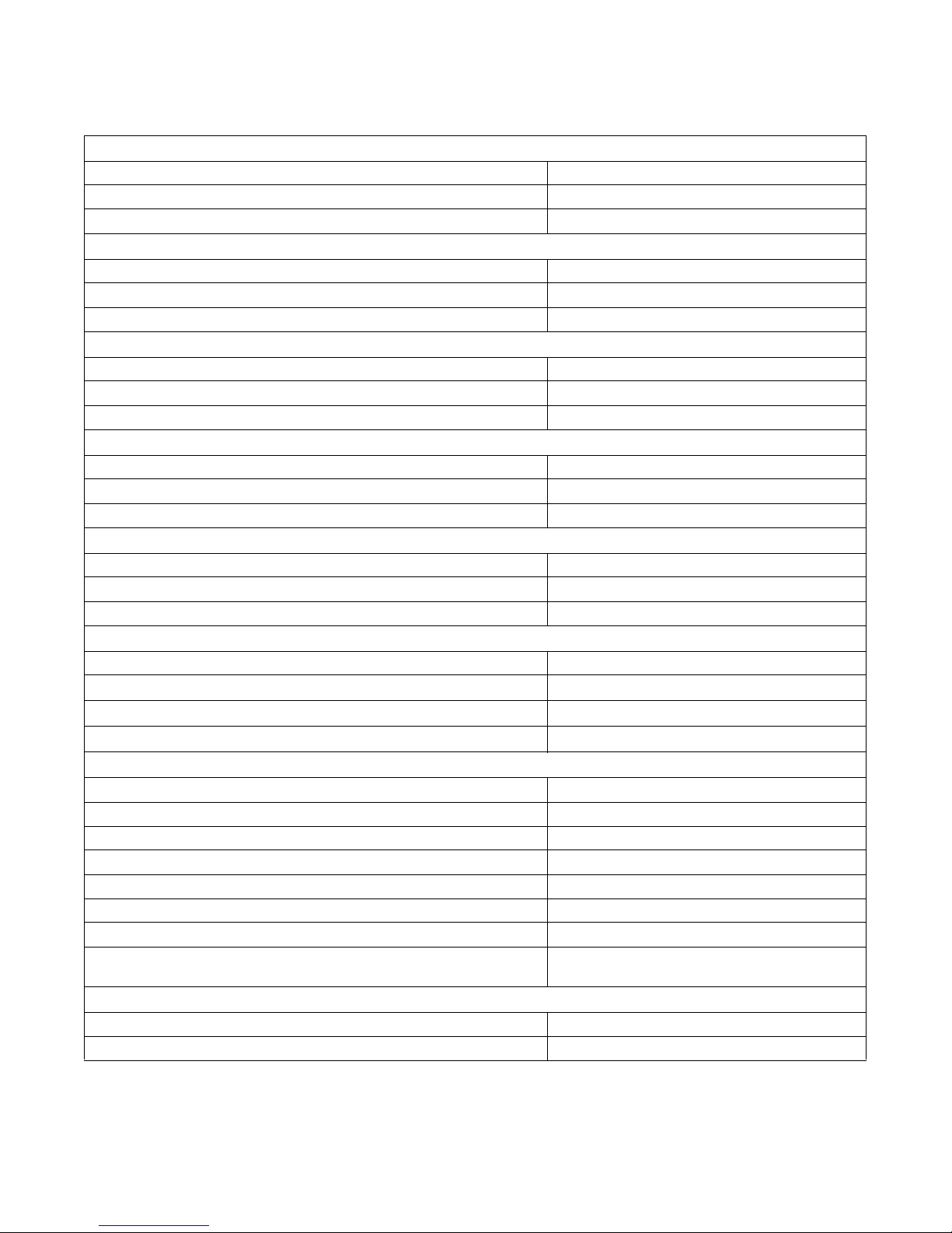
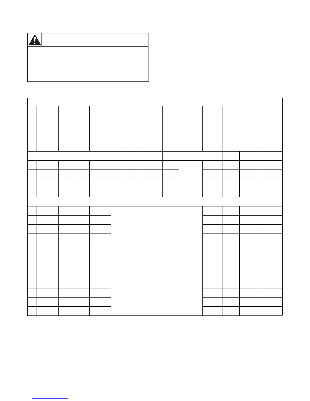
Specifications and Dimensions - Model IWF014 (2-speed)
Capacity (dry weight) Ratio (kg/l)
1:11
1:10
1:9
Cylinder
Cylinder diameter, in. (mm)
Cylinder depth, in. (mm)
Cylinder volume, ft.3 (l)
Cabinet
Overall height, in. (mm)
Overall width, in. (mm)
Overall depth, in. (mm)
Front Loading
Door opening size, in. (mm)
Height of door bottom above floor, in (mm)
Height of door center above floor, in (mm)
Speed
Was h
Distribution
Spin
G-factor
Spin
Motor (3 phase), 4p, 1470 tr/min
Drain Valve, in. (mm)
Water Supply (hard, soft, warm water), in. (mm)
Direct Steam Heating
Steam inlet connection size, in. (mm)
Electrical
Electrical Heating (230/400 V)
Electrical Heating (400V)
Steam
Warm Water (without additional heating)
Warm Water (with additional heating)
Packing Dimensions (height X width X depth), in. (mm)
Weight
Net weight, lb. (kg)
Gross weight, lb. (kg)
15.87 lb. (7.2 kg)
10-50 tr/min - RPM
85 tr/min - RPM
525 tr/min - RPM
0.5 HP/0.37 kW
4.2 kW - 6 kW - 9 kW
45.66 X 28.74 X 33.46
(1160 X 730 X 850)
13 lb. (5.9 kg)
14 lb. (6.5 kg)
20.86 (530)
11.61 (295)
2.29 (65)
40.98 (1041)
25.98 (660)
31.37 (797)
11.81 (300)
13.97 (355)
20 (508)
82
2 (51)
.75 (19)
.38 (10)
Not Applicable
Not Applicable
Not Applicable
Not Applicable
384 (174)
423.28 (192)
3
© Copyright, Alliance Laundry Systems LLC – DO NOT COPY or TRANSMIT
5-08-51
Page 5
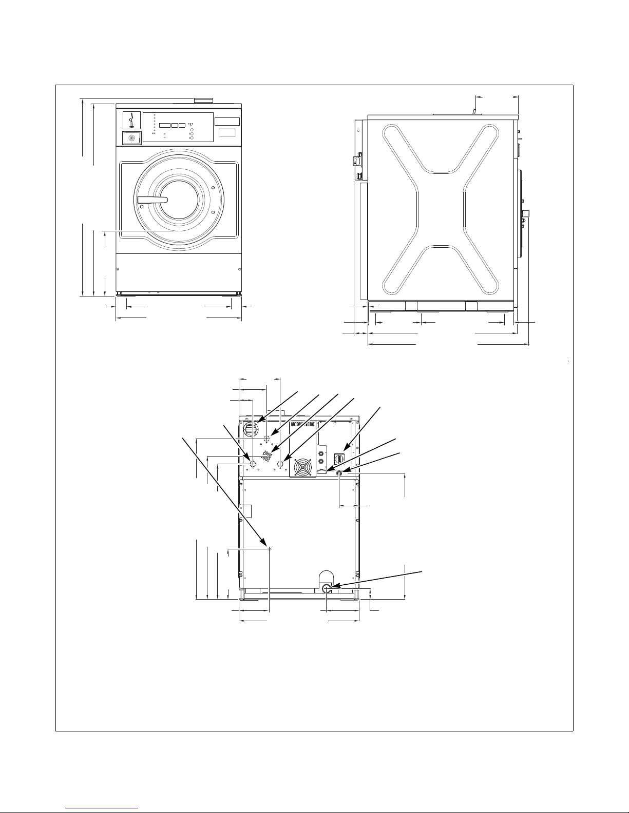
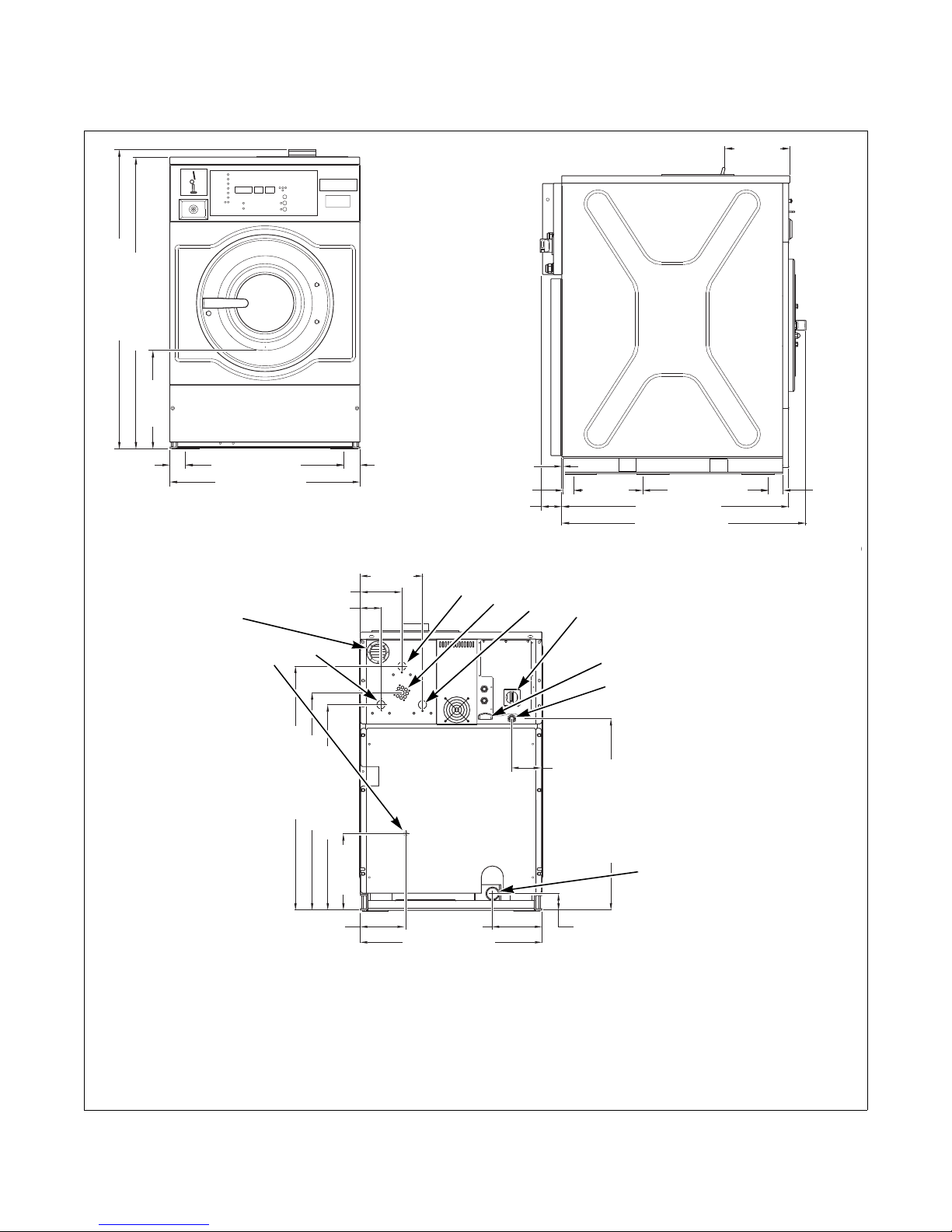
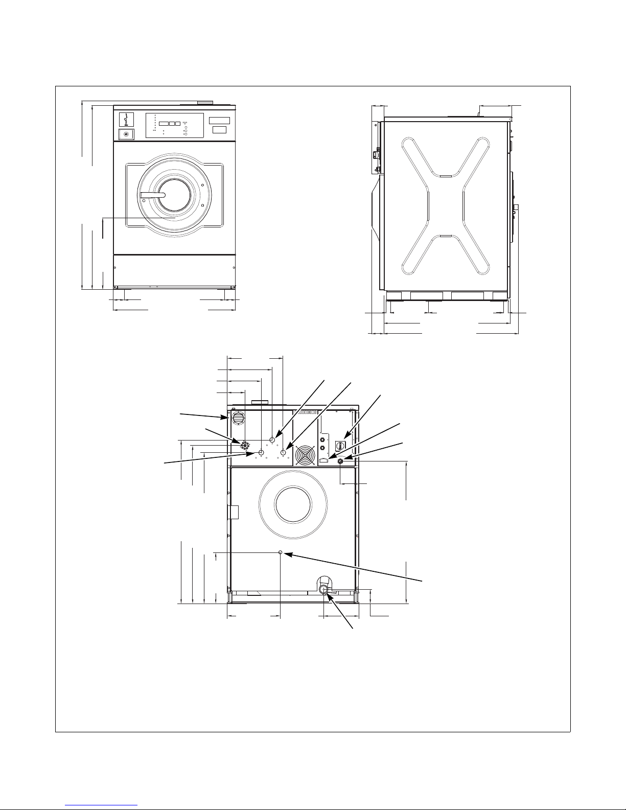
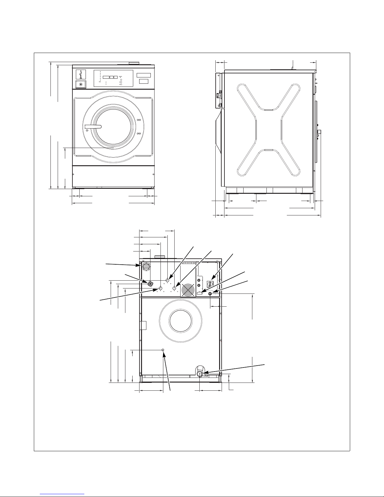
Machine Dimensions - Model IWF014 (2-speed)
CHM2099N
CHM2100N
40.98 in. (1041 mm)
39.92 in. (1014 mm)
25.98 in. (660 mm)
0.2 in.
(5 mm)
8.66 in.
(220 mm)
21.65 in. (550 mm)
2.17 in.
(55 mm)
13.98 in.
(355 mm)
25.98 in. (660 mm)
2.17 in.
(55 mm)
1.46 in. (37 mm)
2.72 in. (69 mm)
11.3 in. (287 mm)
10.75 in.
(273 mm)
26.37 in. (670 mm)
28.66 in (728 mm)
CHM2100N
CHM2110N
1.89 in.
(48 mm)
8.9 in.
(226 mm)
2.95 in. (75 mm)
5.94 in. (151 mm)
34.92 in. (887 mm)
31.14 in. (791 mm)
29.41 in. (747 mm)
10.92 in.
(277.5 mm)
27.42 in. (696.5 mm)
4.29 in.
(109 mm)
6.48 in.
(164.5 mm)
7.09 in.
(180 mm)
2.36 in.
(60 mm)
1
2
4
8
6
3
7
9
10
5
CHM2099N
Washer-Extractors
1 Ventilation Soap Dispenser 6 Ventilation Tub
2 Warm Water Connections .75 in. 7 Electrical Connections
3 Liquid Soap Connections 8 Drain Valve
4 Soft Water Connections .75 in. 9 Steam Connections
5 Main Switch 10 Hard Water Connections .75 in.
Figure 2
5-08-51
© Copyright, Alliance Laundry Systems LLC – DO NOT COPY or TRANSMIT
4
Page 6
Washer-Extractors
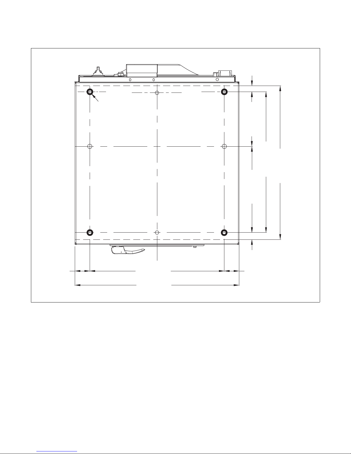
2.17 in.
(55 mm)
21.65 in. (550 mm)
10.75 in. (273 mm)
1.46 in.
(37 mm)
22.05 in. (560 mm)
25.4 in. (645 mm)
11.3 in. (287 mm)
2.17 in.
(55 mm)
25.98 in. (660 mm)
ø0.87 in.
(ø22 mm)
1.89 in.
(48 mm)
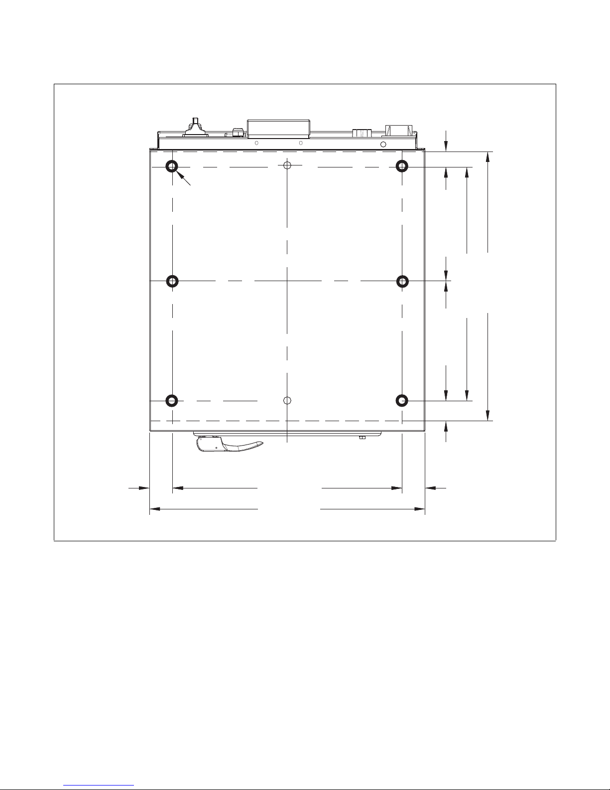
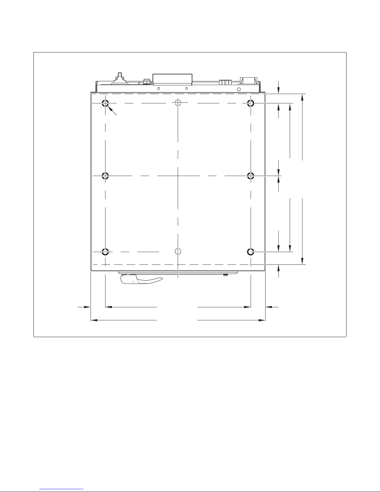
Mounting Bolt Hole Locations - Model IWF014 (2-speed)
Figure 3
CHM2156N
5
© Copyright, Alliance Laundry Systems LLC – DO NOT COPY or TRANSMIT
5-08-51
Page 7
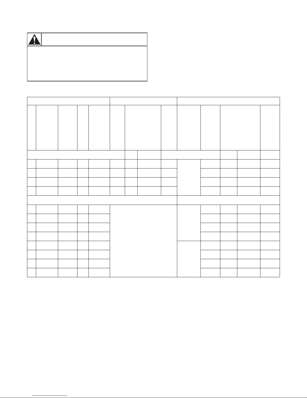
Electrical Installation Requirements - Model IWF014 (2-speed)
Only trained personnel should perform this
procedure. Use caution while servicing
machines with covers removed and power
applied.
W700
WARNING
Washer-Extractors
Boiler Fed/Steam Heat Electric Heat
Heating Elements
kW Standard
Full Load
Recommended
Circuit Breaker
(US-market)
Amps
2
Code
Recommended
Circuit Breaker
Voltage
Cycle
Phase
Wire
Full Load
Amps
(US-market)
AWG/mm
US NON-US US NON-US
N 440-480 50/60 3 3+PE 1 10 6 14/2.5
N/A N/A N/A
P 380-415 50/60 3 3+N+PE 1 10 6 14/2.5 11.9 15 16
3x2 kW
Q 200-240 50/60 3 3+PE 2.5 10 6 14/2.5 18.9 25 20
X 200-240 50/60 1/3 2/3+PE 2.5 10 6 14/2.5 N/A N/A N/A
Alternative Electric Heat Options
N 440-480 50/60 3 3+PE
N/A N/A N/A
P 380-415 50/60 3 3+N+PE 8.6 10 10
3x1.4 kW
Q 200-240 50/60 3 3+PE 14 15 16
X 200-240 50/60 1/3 2/3+PE N/A N/A N/A
N 440-480 50/60 3 3+PE
N/A N/A N/A
AWG/mm
2
N/A
14/2.5
14/2.5
N/A
N/A
14/2.5
14/2.5
N/A
N/A
P 380-415 50/60 3 3+N+PE 17.3
Q 200-240 50/60 3 3+PE
X 200-240 50/60 1/3 2/3+PE N/A N/A N/A
5-08-51
© Copyright, Alliance Laundry Systems LLC – DO NOT COPY or TRANSMIT
Table 1
3x3 kW
27.1
25 20
30 25
14/2.5
14/2.5
N/A
6
Page 8
Washer-Extractors
Specifications and Dimensions - Model IWF018 (2-speed)
Capacity (dry weight) Ratio (kg/l)
1:11
1:10
1:9
Cylinder
Cylinder diameter, in. (mm)
Cylinder depth, in. (mm)
Cylinder volume, ft.3 (l)
Cabinet
Overall height, in. (mm)
Overall width, in. (mm)
Overall depth, in. (mm)
Front Loading
Door opening size, in. (mm)
Height of door bottom above floor, in (mm)
Height of door center above floor, in (mm)
Speed
Was h
Distribution
Spin
G-factor
Spin
Motor (3 phase), 4p, 1470 tr/min
Drain Valve, in. (mm)
Water Supply (hard, soft, warm water), in. (mm)
Direct Steam Heating
Steam inlet connection size, in. (mm)
Electrical
Electrical Heating (230/400 V)
Electrical Heating (400V)
Steam
Warm Water (without additional heating)
Warm Water (with additional heating)
Packing Dimensions (height X width X depth), in. (mm)
Weight
Net weight, lb. (kg)
Gross weight, lb. (kg)
14.33 lb. (6.9 kg)
16.09 lb. (7.3 kg)
18.51 lb. (8.4 kg)
10-50 tr/min - RPM
85 tr/min - RPM
525 tr/min - RPM
0.5 HP/0.37 kW
4.2 kW - 6 kW - 9 kW
Not Applicable
Not Applicable
Not Applicable
45.66 X 28.74 X 33.46
(1160 X 730 X 850)
20.86 (530)
13.58 (345)
2.57 (73)
40.98 (1041)
25.98 (660)
31.37 (797)
11.81 (300)
13.97 (355)
20 (508)
82
2 (51)
.75 (19)
.38 (10)
12 kW
399.03 (181)
432.10 (196)
7
© Copyright, Alliance Laundry Systems LLC – DO NOT COPY or TRANSMIT
5-08-51
Page 9
Machine Dimensions - Model IWF018 (2-speed)
CHM2099N
CHM2100
40.98 in. (1041 mm)
39.92 in. (1014 mm)
25.98 in. (660 mm)
0.2 in.
(5 mm)
8.66 in.
(220 mm)
21.65 in. (550 mm)
2.17 in.
(55 mm)
13.98 in.
(355 mm)
25.98 in. (660 mm)
2.17 in.
(55 mm)
1.46 in. (37 mm)
2.72 in. (69 mm)
12.87 in. (327 mm)
9.17 in.
(233 mm)
26.37 in. (670 mm)
28.66 in (728 mm)
CHM2110N
1.89 in.
(48 mm)
8.9 in.
(226 mm)
2.95 in. (75 mm)
5.94 in. (151 mm)
34.92 in. (887 mm)
31.14 in. (791 mm)
29.41 in. (747 mm)
10.92 in.
(277.5 mm)
27.42 in. (696.5 mm)
4.29 in.
(109 mm)
6.48 in.
(164.5 mm)
7.09 in.
(180 mm)
2.36 in.
(60 mm)
1
2
4
8
6
3
7
9
10
5
CHM2100N
CHM2099N
Washer-Extractors
1 Warm Water Connections .75 in. 6 Electrical Connections
2 Liquid Soap Connections 7 Drain Valve
3 Soft Water Connections .75 in. 8 Steam Connections
4 Main Switch 9 Hard Water Connections .75 in.
5 Ventilation Tub 10 Ventilation Soap Dispenser
5-08-51
© Copyright, Alliance Laundry Systems LLC – DO NOT COPY or TRANSMIT
Figure 4
8
Page 10
Washer-Extractors
2.17 in.
(55 mm)
21.65 in. (550 mm)
10.75 in. (273 mm)
1.46 in.
(37 mm)
22.05 in. (560 mm)
25.4 in. (645 mm)
11.3 in. (287 mm)
2.17 in.
(55 mm)
25.98 in. (660 mm)
ø0.87 in.
(ø22 mm)
1.89 in.
(48 mm)
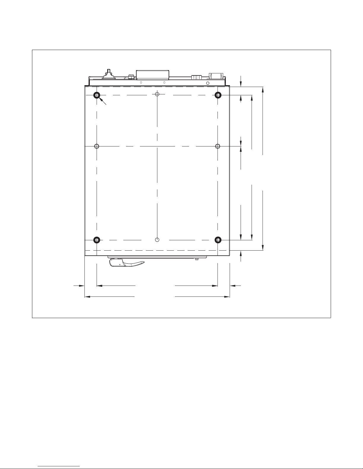
Mounting Bolt Hole Locations - Model IWF018 (2-speed)
Figure 5
CHM2105N
9
© Copyright, Alliance Laundry Systems LLC – DO NOT COPY or TRANSMIT
5-08-51
Page 11

Electrical Installation Requirements - Model IWF018 (2-speed)
Only trained personnel should perform this
procedure. Use caution while servicing
machines with covers removed and power
applied.
W700
WARNING
Washer-Extractors
Boiler Fed/Steam Heat Electric Heat
Heating Elements
kW Standard
Full Load
Recommended
Circuit Breaker
(US-market)
Amps
2
Code
Recommended
Circuit Breaker
Voltage
Cycle
Phase
Wire
Full Load
Amps
(US-market)
AWG/mm
US NON-US US NON-US
N 440-480 50/60 3 3+PE 1 10 6 14/2.5
N/A N/A N/A
P 380-415 50/60 3 3+N+PE 1 10 6 14/2.5 11.9 15 16
3x2 kW
Q 200-240 50/60 3 3+PE 2.5 10 6 14/2.5 18.9 25 20
X 200-240 50/60 1/3 2/3+PE 2.5 10 6 14/2.5 N/A N/A N/A
Alternative Electric Heat Options
N 440-480 50/60 3 3+PE
N/A N/A N/A
P 380-415 50/60 3 3+N+PE 8.6 10 10
3x1.4 kW
Q 200-240 50/60 3 3+PE 14 15 16
X 200-240 50/60 1/3 2/3+PE N/A N/A N/A
N 440-480 50/60 3 3+PE
N/A N/A N/A
AWG/mm
2
N/A
14/2.5
14/2.5
N/A
N/A
14/2.5
14/2.5
N/A
N/A
P 380-415 50/60 3 3+N+PE 17.3
Q 200-240 50/60 3 3+PE
X 200-240 50/60 1/3 2/3+PE N/A N/A N/A
N 440-480 50/60 3 3+PE
P 380-415 50/60 3 3+N+PE
Q 200-240 50/60 3 3+PE N/A N/A N/A
X 200-240 50/60 1/3 2/3+PE N/A N/A N/A
5-08-51
© Copyright, Alliance Laundry Systems LLC – DO NOT COPY or TRANSMIT
Table 2
3x3 kW
3x4 kW
27.1
19.8
22.8
25 20
30 25
25 20
30 25
14/2.5
14/2.5
N/A
14/2.5
14/2.5
N/A
N/A
10
Page 12

Washer-Extractors
Specifications and Dimensions - Model IWF025 (2-speed)
Capacity (dry weight) Ratio (kg/l)
1:11
1:10
1:9
Cylinder
Cylinder diameter, in. (mm)
Cylinder depth, in. (mm)
Cylinder volume, ft.3 (l)
Cabinet
Overall height, in. (mm)
Overall width, in. (mm)
Overall depth, in. (mm)
Front Loading
Door opening size, in. (mm)
Height of door bottom above floor, in (mm)
Height of door center above floor, in (mm)
Speed
Was h
Distribution
Spin
G-factor
Spin
Motor (3 phase), 4p, 1470 tr/min
Drain Valve, in. (mm)
Water Supply (hard, soft, warm water), in. (mm)
Direct Steam Heating
Steam inlet connection size, in. (mm)
Electrical
Electrical Heating (230/400 V)
Electrical Heating (400V)
Steam
Warm Water (without additional heating)
Warm Water (with additional heating)
Packing Dimensions (height X width X depth), in. (mm)
Weight
Net weight, lb. (kg)
Gross weight, lb. (kg)
18.95 lb. (8.6 kg)
20.94 lb. (9.5 kg)
23.14 lb. (10.5 kg)
10-50 tr/min - RPM
85 tr/min - RPM
525 tr/min - RPM
0.5 HP/0.37 kW
4.2 kW - 6kW - 9 kW
Not Applicable
Not Applicable
Not Applicable
45.66 X 28.74 X 37.40
(1170 X 730 X 950)
20.86 (530)
17.32 (440)
3.35 (95)
40.98 (1041)
25.98 (660)
35.31 (897)
11.81 (300)
13.97 (355)
20 (508)
82
2 (51)
.75 (19)
.38 (10)
12 kW
440.92 (200)
460.76 (209)
11
© Copyright, Alliance Laundry Systems LLC – DO NOT COPY or TRANSMIT
5-08-51
Page 13

Machine Dimensions - Model IWF025 (2-speed)
CHM2100
40.98 in. (1041 mm)
39.92 in. (1014 mm)
25.98 in. (660 mm)
0.2 in.
(5 mm)
8.66 in.
(220 mm)
21.65 in. (550 mm)
2.17 in.
(55 mm)
13.98 in.
(355 mm)
25.98 in. (660 mm)
2.17 in.
(55 mm)
1.46 in. (37 mm)
2.72 in. (69 mm)
16.81 in. (427 mm)
9.17 in.
(233 mm)
30.31 in. (770 mm)
32.6 in (828 mm)
CHM2110N
1.89 in.
(48 mm)
8.9 in.
(226 mm)
2.95 in. (75 mm)
5.94 in. (151 mm)
34.92 in. (887 mm)
31.14 in. (791 mm)
29.41 in. (747 mm)
10.92 in.
(277.5 mm)
27.42 in. (696.5 mm)
4.29 in.
(109 mm)
6.48 in.
(164.5 mm)
7.09 in.
(180 mm)
2.36 in.
(60 mm)
1
2
4
8
6
3
7
9
10
5
CHM2099N
CHM2100N
CHM2099N
Washer-Extractors
1 Warm Water Connections .75 in. 6 Electrical Connections
2 Liquid Soap Connections 7 Drain Valve
3 Soft Water Connections .75 in. 8 Steam Connections
4 Main Switch 9 Hard Water Connections .75 in.
5 Ventilation Tub 10 Ventilation Soap Dispenser
5-08-51
© Copyright, Alliance Laundry Systems LLC – DO NOT COPY or TRANSMIT
Figure 6
12
Page 14
Washer-Extractors
CHM2158N
2.17 in.
(55 mm)
21.65 in. (550 mm)
9.17 in. (233 mm)
1.46 in.
(37 mm)
25.99 in. (660 mm)
29.33 in. (745 mm)
16.81 in. (427 mm)
2.17 in.
(55 mm)
25.98 in. (660 mm)
ø0.87 in.
(ø22 mm)
1.89 in.
(48 mm)
Mounting Bolt Hole Locations - Model IWF025 (2-speed)
Figure 7
CHM2158N
13
© Copyright, Alliance Laundry Systems LLC – DO NOT COPY or TRANSMIT
5-08-51
Page 15
Electrical Installation Requirements - Model IWF025 (2-speed)
Only trained personnel should perform this
procedure. Use caution while servicing
machines with covers removed and power
applied.
W700
WARNING
Washer-Extractors
Boiler Fed/Steam Heat Electric Heat
Heating Elements
kW Standard
Full Load
Recommended
Circuit Breaker
(US-market)
Amps
2
Code
Recommended
Circuit Breaker
Voltage
Cycle
Phase
Wire
Full Load
Amps
(US-market)
AWG/mm
US NON-US US NON-US
N 440-480 50/60 3 3+PE 1 10 6 14/2.5
N/A N/A N/A
P 380-415 50/60 3 3+N+PE 1 10 6 14/2.5 17.3 25 20
3x3 kW
Q 200-240 50/60 3 3+PE 2.5 10 6 14/2.5 27.1 30 25
X 200-240 50/60 1/3 2/3+PE 2.5 10 6 14/2.5 N/A N/A N/A
Alternative Electric Heat Options
N 440-480 50/60 3 3+PE
N/A N/A N/A
P 380-415 50/60 3 3+N+PE 8.6 10 10
3x1.4 kW
Q 200-240 50/60 3 3+PE 14 15 16
X 200-240 50/60 1/3 2/3+PE N/A N/A N/A
N 440-480 50/60 3 3+PE
N/A N/A N/A
AWG/mm
2
N/A
14/2.5
14/2.5
N/A
N/A
14/2.5
14/2.5
N/A
N/A
P 380-415 50/60 3 3+N+PE 11.9
Q 200-240 50/60 3 3+PE
X 200-240 50/60 1/3 2/3+PE N/A N/A N/A
N 440-480 50/60 3 3+PE
P 380-415 50/60 3 3+N+PE 22.8
Q 200-240 50/60 3 3+PE N/A N/A N/A
X 200-240 50/60 1/3 2/3+PE N/A N/A N/A
5-08-51
© Copyright, Alliance Laundry Systems LLC – DO NOT COPY or TRANSMIT
Table 3
3x2 kW
3x4 kW
15 16
18.9
25 20
19.8 25 20
30 25
14/2.5
14/2.5
N/A
14/2.5
14/2.5
N/A
N/A
14
Page 16

Washer-Extractors
Specifications and Dimensions - Models IWF030 (2-speed)
Capacity (dry weight) Ratio (kg/l)
1:11
1:10
1:9
Cylinder
Cylinder diameter, in. (mm)
Cylinder depth, in. (mm)
Cylinder volume, ft.3 (l)
Cabinet
Overall height, in. (mm)
Overall width, in. (mm)
Overall depth, in. (mm)
Front Loading
Door opening size, in. (mm)
Height of door bottom above floor, in (mm)
Height of door center above floor, in (mm)
Speed
Was h
Distribution
Spin
G-factor
Spin
Motor (3 phase), 4p, 1470 tr/min
Drain Valve, in. (mm)
Water Supply (hard, soft, warm water), in. (mm)
Direct Steam Heating
Steam inlet connection size, in. (mm)
Electrical
Electrical Heating (230/400 V)
Electrical Heating (400V)
Steam
Warm Water (without additional heating)
Warm Water (with additional heating)
Packing Dimensions (height X width X depth), in. (mm)
Weight
Net weight, lb. (kg)
Gross weight, lb. (kg)
26.45 lb. (12 kg)
29.10 lb. (13.2 kg)
31.96 lb. (14.5 kg)
25.59 (650)
17.74 (400)
47.40 (1204)
30.70 (780)
33.14 (842)
11.81 (300)
17.91 (455)
23.85 (606)
10-50 tr/min - RPM
85 tr/min - RPM
475 tr/min - RPM
1 HP/0.75 kW
12 kW - 15 kW - 18 kW
Not Applicable
Not Applicable
Not Applicable
Not Applicable
52.75 X 33.38 X37.40
(1340 X 848 X 950)
617.29 (280)
645.95 (293)
4.66 (132)
82
2 (51)
.75 (19)
.38 (10)
15
© Copyright, Alliance Laundry Systems LLC – DO NOT COPY or TRANSMIT
5-08-51
Page 17
Machine Dimensions - Model IWF030 (2-speed)
CHM2117N
CHM2119N
47.4 in. (1204 mm)
46.26 in. (1175 mm)
12.4 in.
(315 mm)
1.1 in.
(28 mm)
8.66 in.
(220 mm)
25.2 in. (640 mm)
2.76 in.
(70 mm)
17.91 in.
(455 mm)
30.71 in. (780 mm)
2.76 in.
(70 mm)
3.23 in.
(82 mm)
16.14 in. (410 mm)
10.24 in.
(260 mm)
29.92 in. (760 mm)
32.12 (816 mm)
CHM2118N
1.3 in.
(33 mm)
13.07 in.
(332 mm)
7.95 in. (202 mm)
10.51 in. (267 mm)
38.15 in. (969 mm)
36.85 in. (936 mm)
35.2 in. (894 mm)
11.89 in.
(302 mm)
33.19 in. (843 mm)
4.29 in.
(109 mm)
8.23 in.
(209 mm)
3.31 in.
(84 mm)
1
2
4
8
7
3
6
9
10
5
CHM2117N
3.31 in.
(84 mm)
4.19 in. (106.5 mm)
CHM2119N
Washer-Extractors
1 Warm Water Connections .75 in. 6 Steam Connections
2 Soft Water Connections .75 in. 7 Drain Valve
3 Main Switch 8 Hard Water Connections .75 in.
4 Ventilation Tub 9 Liquid Soap Connections
5 Electrical Connections 10 Ventilation Soap Dispenser
5-08-51
© Copyright, Alliance Laundry Systems LLC – DO NOT COPY or TRANSMIT
Figure 8
16
Page 18
Washer-Extractors
2.76 in.
(70 mm)
25.2 in. (640 mm)
10.24 in. (260 mm)
1.1 in.
(28 mm)
26.38 in. (670 mm)
28.78 in. (731 mm)
16.14 in. (410 mm)
2.76 in.
(70 mm)
30.71 in. (780 mm)
ø0.87 in.
(ø22 mm)
1.3 in.
(33 mm)
Mounting Bolt Hole Locations - Model IWF030 (2-speed)
Figure 9
CHM2159N
17
© Copyright, Alliance Laundry Systems LLC – DO NOT COPY or TRANSMIT
5-08-51
Page 19

Electrical Installation Requirements - Model IWF030 (2-speed)
Only trained personnel should perform this
procedure. Use caution while servicing
machines with covers removed and power
applied.
W700
WARNING
Washer-Extractors
Boiler Fed/Steam Heat Electric Heat
Heating Elements
kW Standard
Full Load
Recommended
Circuit Breaker
(US-market)
Amps
2
Code
Recommended
Circuit Breaker
Voltage
Cycle
Phase
Wire
Full Load
Amps
(US-market)
AWG/mm
US NON-US US NON-US
N 440-480 50/60 3 3+PE 1 10 6 14/2.5
19.8 25 20
P 380-415 50/60 3 3+N+PE 1 10 6 14/2.5 22.8 30 25
6x2 kW
Q 200-240 50/60 3 3+PE 2.5 10 6 14/2.5 35.3 40 40
X 200-240 50/60 1/3 2/3+PE 2.5 10 6 14/2.5 N/A N/A N/A
Alternative Electric Heat Options
N 440-480 50/60 3 3+PE
P 380-415 50/60 3 3+N+PE 28.2 40 32
3x3 kW
24.5 30 25
+
Q 200-240 50/60 3 3+PE 43.5 40 50
3x2 kW
X 200-240 50/60 1/3 2/3+PE N/A N/A N/A
N 440-480 50/60 3 3+PE
29.2 40 32
AWG/mm
2
14/2.5
14/2.5
12/4.0
N/A
14/2.5
12/2.5
12/4.0
N/A
12/4.0
P 380-415 50/60 3 3+N+PE 33.7
Q 200-240 50/60 3 3+PE
X 200-240 50/60 1/3 2/3+PE N/A N/A N/A
5-08-51
© Copyright, Alliance Laundry Systems LLC – DO NOT COPY or TRANSMIT
Table 4
6x3 kW
51.8
40 40
50 63
12/4.0
10/6.0
N/A
18
Page 20

Washer-Extractors
Ensure that the machine is installed on a
level floor of sufficient strength and that
the recommended clearances for
inspection and maintenance are provided.
Never allow the inspection and
maintenance space to be blocked.
SW020
CAUTION
1
1
2
3
7
4
6
2
3
5
Installation
Models IWF014, IWF018, IWF025 and
IWF030 (2-speed)
Surface
The machine must be securely fixed on a flat surface
(metal base, concrete or solid ground). The anchoring
is to be done on the 4 provided places in the holes on
the corners of the base. (See Mounting Bolt Hole
Locations). Refer to Figure 10.
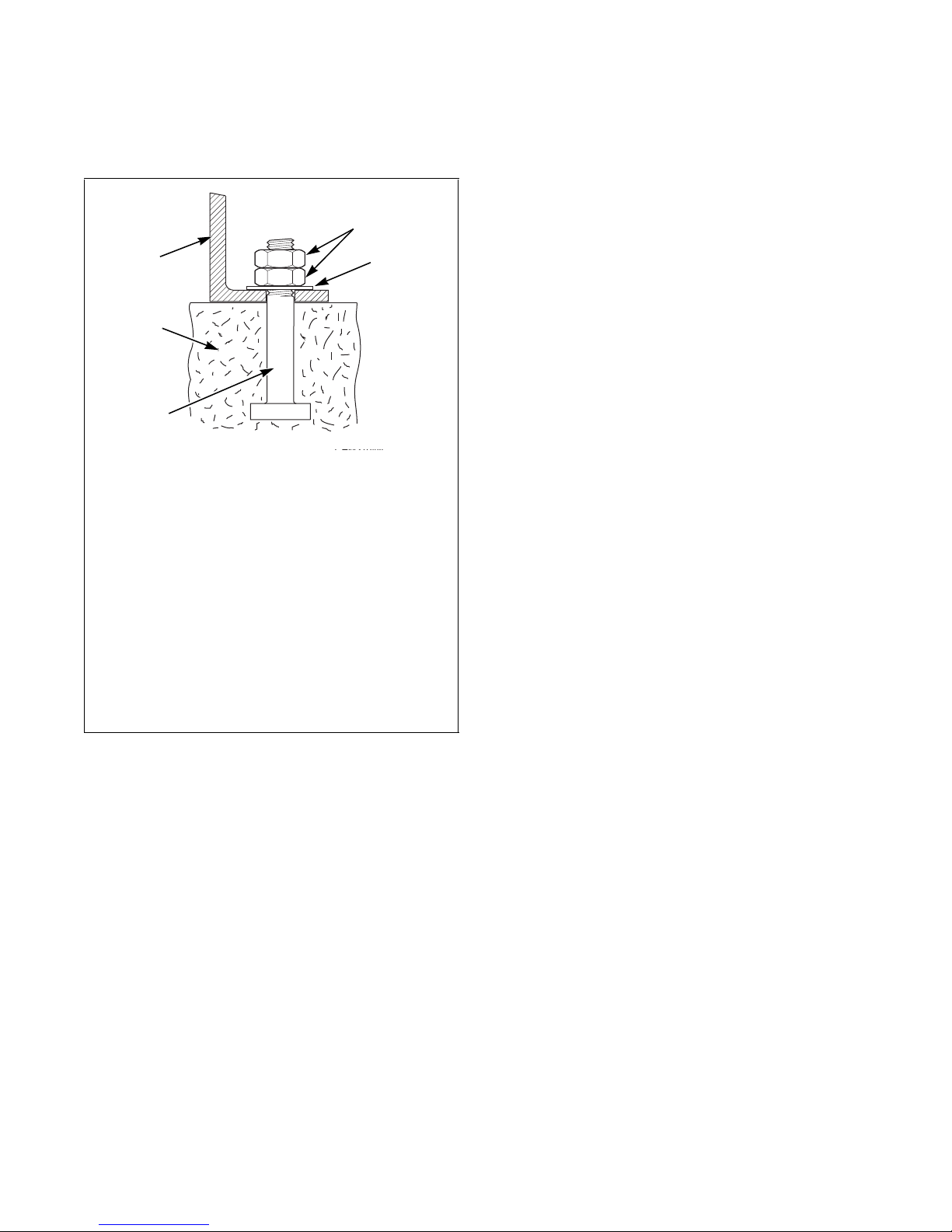
Anchoring to Metal Base
The machines must be fixed on a metal base which is
securely anchored on a concrete base. Refer to
Figure 11.
CHM2103N
1 Machine Base
2 Nut
.5 in. (M12) (Models IWF014, IWF018 and
IWF025), .625 in. (M16) (Model IWF030)
3 Washer
1.57 in. x 0.60 in. x 0.15 in.
(40 mm x 17 mm x 4 mm)
4 Bolt
.625 in. x 2.5 in. (M16x60 mm)
5 Bolt
.5 in. (M12) (Models IWF014, IWF018 and
IWF025), and .625 in. (M16) (Model IWF030)
6 Concrete Base
4 in. (101 mm)
7 Metal Base
CHM2102N
1 Mounting Bolt Holes
Figure 10
The machine must be placed entirely level. For easy
maintenance it is recommended to keep a minimal
distance of 23.62 in. (600 mm) between the wall and
the back of the machine.
If several machines are placed next to each other, there
should be a minimal distance of 1.18 in. (30 mm)
between each machine.
19
© Copyright, Alliance Laundry Systems LLC – DO NOT COPY or TRANSMIT
Figure 11
CHM2102N
5-08-51
Page 21
Directly to Concrete Base
5
1
2
3
4
The machine must be anchored directly to concrete
base. Refer to Figure 12.
CHM2104N
1 Nut
.5 in. (M12) (Models IWF014, IWF018 and
IWF025), and .625 (M16) (Model IWF030)
2 Washer
1.57 in. x 0.60 in. x 0.15 in.
(40 mm x 17 mm x 4 mm)
3 Bolt
.5 in. (M12) (Models IWF014, IWF018 and
IWF025), and .625 (M16) (Model IWF030)
4 Concrete Base
9.48 in. (250 mm) (Models IWF014, IWF018
and IWF025), and 13.77 in. (350 mm)
(Model IWF030)
5 Machine Base
Washer-Extractors
Figure 12
IMPORTANT: Machine bolts should be re-checked
on a quarterly basis.
5-08-51
© Copyright, Alliance Laundry Systems LLC – DO NOT COPY or TRANSMIT
20
Page 22

Washer-Extractors
Specifications and Dimensions - Models IWF033 (2-speed)
Capacity (dry weight) Ratio (kg/l)
1:11
1:10
1:9
Cylinder
Cylinder diameter, in. (mm)
Cylinder depth, in. (mm)
Cylinder volume, ft.3 (l)
Cabinet
Overall height, in. (mm)
Overall width, in. (mm)
Overall depth, in. (mm)
Front Loading
Door opening size, in. (mm)
Height of door bottom above floor, in (mm)
Height of door center above floor, in (mm)
Speed
Was h
Distribution
Spin
G-factor
Spin
Motor (3 phase), 4p, 1470 tr/min
Drain Valve, in. (mm)
Water Supply (hard, soft, warm water), in. (mm)
Direct Steam Heating
Steam inlet connection size, in. (mm)
Electrical
Electrical Heating (230/400 V)
Electrical Heating (400V)
Steam
Warm Water (without additional heating)
Warm Water (with additional heating)
Packing Dimensions (height X width X depth), in. (mm)
Weight
Net weight, lb. (kg)
Gross weight, lb. (kg)
28.88 lb. (13.1 kg)
31.96 lb. (14.5 kg)
35.49 lb. (16.1 kg)
26.77 (680)
17.74 (400)
47.40 (1204)
30.70 (780)
33.14 (842)
15.74 (400)
15.35 (390)
23.22 (590)
10-50 tr/min - RPM
85 tr/min - RPM
465 tr/min - RPM
1.47 HP/1.1 kW
12 kW - 15 kW - 18 kW
21 kW - 24 kW
Not Applicable
Not Applicable
Not Applicable
52.75 X 33.38 X 36.22
(1340 X 848 X 920)
674.61 (306)
723.11 (328)
5.12 (145)
82
2 (51)
.75 (19)
.38 (10)
21
© Copyright, Alliance Laundry Systems LLC – DO NOT COPY or TRANSMIT
5-08-51
Page 23
Machine Dimensions - Model IWF033 (2-speed)
CHM2120N
47.4 in. (1204 mm)
46.26 in. (1175 mm)
8.86 in.
(225 mm)
1.1 in. (28 mm)
8.66 in.
(220 mm)
25.2 in. (640 mm)
2.76 in.
(70 mm)
15.35 in.
(390 mm)
30.71 in. (780 mm)
2.76 in.
(70 mm)
16.14 in. (410 mm)
10.24 in.
(260 mm)
29.92 in. (760 mm)
32.12 (816 mm)
CHM2121N
1.3 in.
(33 mm)
13.07 in.
(332 mm)
7.95 in. (202 mm)
10.51 in. (267 mm)
38.15 in. (969 mm)
36.85 in. (936 mm)
35.2 in. (894 mm)
12.2 in.
(310 mm)
33.19 in. (843 mm)
4.29 in.
(109 mm)
8.23 in.
(209 mm)
8
1
3
7
5
2
6
9
10
4
3.31 in.
(84 mm)
4.17 in. (106 mm)
CHM2122N
3.23 in. (82 mm)
CHM2120N
3.31 in.
(84 mm)
Washer-Extractors
CHM2121N
1 Warm Water Connections .75 in. 6 Drain Valve
2 Soft Water Connections .75 in. 7 Steam Connections
3 Main Switch 8 Hard Water Connections .75 in.
4 Ventilation Tub 9 Liquid Soap Connections
5 Electrical Connections 10 Ventilation Soap Dispenser
5-08-51
© Copyright, Alliance Laundry Systems LLC – DO NOT COPY or TRANSMIT
Figure 13
22
Page 24

Washer-Extractors
2.76 in.
(70 mm)
25.2 in. (640 mm)
10.24 in. (260 mm)
1.1 in.
(28 mm)
26.38 in. (670 mm)
28.78 in. (731 mm)
16.14 in. (410 mm)
2.76 in.
(70 mm)
30.71 in. (780 mm)
ø0.87 in.
(ø22 mm)
1.3 in.
(33 mm)
Mounting Bolt Hole Locations - Model IWF033 (2-speed)
Figure 14
CHM2160N
23
© Copyright, Alliance Laundry Systems LLC – DO NOT COPY or TRANSMIT
5-08-51
Page 25

Electrical Installation Requirements - Model IWF033 (2-speed)
Only trained personnel should perform this
procedure. Use caution while servicing
machines with covers removed and power
applied.
W700
WARNING
Washer-Extractors
Boiler Fed/Steam Heat Electric Heat
Heating Elements
kW Standard
Full Load
Recommended
Circuit Breaker
(US-market)
Amps
2
Code
Recommended
Circuit Breaker
Voltage
Cycle
Phase
Wire
Full Load
Amps
(US-market)
AWG/mm
US NON-US US NON-US
N 440-480 50/60 3 3+PE 4 10 10 14/2.5
30 40 40
P 380-415 50/60 3 3+N+PE 12 15 16 14/2.5 38 50 50
6x3 kW
Q 200-240 50/60 3 3+PE 12 15 16 14/2.5 57 70 70
X 200-240 50/60 1/3 2/3+PE 12 15 16 14/2.5 N/A N/A N/A
Alternative Electric Heat Options
N 440-480 50/60 3 3+PE
P 380-415 50/60 3 3+N+PE 34 40 40
3x3 kW
26 30 30
+
Q 200-240 50/60 3 3+PE 50 60 60
3x2 kW
X 200-240 50/60 1/3 2/3+PE N/A N/A N/A
N 440-480 50/60 3 3+PE
P 380-415 50/60 3 3+N+PE 53
3x3 kW
34 40 40
60 60
+
Q 200-240 50/60 3 3+PE
3x4 kW
N/A
N/A N/A
X 200-240 50/60 1/3 2/3+PE N/A N/A N/A
AWG/mm
2
8/10.0
8/10.0
4/25.0
N/A
10/6.0
8/10.0
6/16.0
N/A
8/10.0
6/16.0
N/A
N/A
N 440-480 50/60 3 3+PE
P 380-415 50/60 3 3+N+PE 30
Q 200-240 50/60 3 3+PE
X 200-240 50/60 1/3 2/3+PE N/A N/A N/A
N 440-480 50/60 3 3+PE
P 380-415 50/60 3 3+N+PE 47
Q 200-240 50/60 3 3+PE
X 200-240 50/60 1/3 2/3+PE N/A N/A N/A
5-08-51
© Copyright, Alliance Laundry Systems LLC – DO NOT COPY or TRANSMIT
Table 5
6x2 kW
6x4 kW
21 30 30
40 40
42
50 50
39 50 50
60 60
N/A
N/A N/A
10/6.0
8/10.0
8/10.0
N/A
8/10.0
6/16.0
N/A
N/A
24
Page 26

Washer-Extractors
Specifications and Dimensions - Model IWF040 (2-speed)
Capacity (dry weight) Ratio (kg/l)
1:11
1:10
1:9
Cylinder
Cylinder diameter, in. (mm)
Cylinder depth, in. (mm)
Cylinder volume, ft.3 (l)
Cabinet
Overall height, in. (mm)
Overall width, in. (mm)
Overall depth, in. (mm)
Front Loading
Door opening size, in. (mm)
Height of door bottom above floor, in (mm)
Height of door center above floor, in (mm)
Speed
Was h
Distribution
Spin
G-factor
Spin
Motor (3 phase), 4p, 1470 tr/min
Drain Valve, in. (mm)
Water Supply (hard, soft, warm water), in. (mm)
Direct Steam Heating
Steam inlet connection size, in. (mm)
Electrical
Electrical Heating (230/400 V)
Electrical Heating (400V)
Steam
Warm Water (without additional heating)
Warm Water (with additional heating)
Packing Dimensions (height X width X depth), in. (mm)
Weight
Net weight, lb. (kg)
Gross weight, lb. (kg)
36.15 lb. (16.4 kg)
39.90 lb. (18.1 kg)
44.31 lb. (20.1 kg)
10-50 tr/min - RPM
85 tr/min - RPM
465 tr/min - RPM
1.47 HP/1.1 kW
2 (51) or 3 (76)
12 kW - 15 kW - 18 kW
21 kW - 24 kW
Not Applicable
Not Applicable
Not Applicable
52.75 X 33.38 X 40.15
(1340 X 848 X 1020)
26.77 (680)
19.68 (500)
6.39 (181)
47.40 (1204)
30.70 (780)
37.08 (942)
15.74 (400)
15.35 (390)
23.22 (590)
82
.75 (19)
.38 (10)
707.68 (321)
758.39 (344)
25
© Copyright, Alliance Laundry Systems LLC – DO NOT COPY or TRANSMIT
5-08-51
Page 27

Machine Dimensions - Model IWF040 (2-speed)
CHM2120N
CHM2121N
CHM2122N
47.4 in. (1204 mm)
46.26 in. (1175 mm)
8.23 in.
(209 mm)
1.1 in.
(28 mm)
8.66 in.
(220 mm)
25.2 in. (640 mm)
2.76 in.
(70 mm)
15.35 in.
(390 mm)
30.71 in. (780 mm)
2.76 in.
(70 mm)
3.23 in.
(82 mm)
10.24 in.
(260 mm)
20.08 in. (510 mm)
33.86 in. (860 mm)
36.07 in. (916 mm)
CHM2121N
CHM2120N
CHM2122N
1.3 in.
(33 mm)
13.07 in.
(332 mm)
7.95 in. (202 mm)
10.51 in. (267 mm)
38.15 in. (969 mm)
36.85 in. (936 mm)
35.2 in. (894 mm)
12.2 in.
(310 mm)
33.19 in. (843 mm)
4.29 in.
(109 mm)
8.86 in.
(225 mm)
3.31 in.
(84 mm)
10
2
4
7
6
3
1
8
9
5
3.31 in.
(84 mm)
4.17 in. (106 mm)
Washer-Extractors
1 Warm Water Connections .75 in. 6 Electrical Connections
2 Hard Water Connections .75 in. 7 Drain Valve
3 Soft Water Connections .75 in. 8 Steam Connections
4 Main Switch 9 Liquid Soap Connections
5 Ventilation Tub 10 Ventilation Soap Dispenser
5-08-51
© Copyright, Alliance Laundry Systems LLC – DO NOT COPY or TRANSMIT
Figure 15
26
Page 28

Washer-Extractors
2.76 in.
(70 mm)
25.2 in. (640 mm)
10.24 in. (260 mm)
1.3 in.
(33 mm)
30.31 in. (770 mm)
32.72 in. (831 mm)
20.08 in. (510 mm)
2.76 in.
(70 mm)
30.71 in. (780 mm)
ø0.87 in.
(ø22 mm)
1.1 in.
(28 mm)
Mounting Bolt Hole Locations - Model IWF040 (2-speed)
Figure 16
CHM2161N
CHM2161N
27
© Copyright, Alliance Laundry Systems LLC – DO NOT COPY or TRANSMIT
5-08-51
Page 29

Electrical Installation Requirements - Model IWF040 (2-speed)
Only trained personnel should perform this
procedure. Use caution while servicing
machines with covers removed and power
applied.
W700
WARNING
Washer-Extractors
Boiler Fed/Steam Heat Electric Heat
Heating Elements
kW Standard
Full Load
Recommended
Circuit Breaker
(US-market)
Amps
2
Code
Recommended
Circuit Breaker
Voltage
Cycle
Phase
Wire
Full Load
Amps
(US-market)
AWG/mm
US NON-US US NON-US
N 440-480 50/60 3 3+PE 4 10 10 14/2.5
30 40 40
P 380-415 50/60 3 3+N+PE 12 15 16 14/2.5 38 50 50
6x3 kW
Q 200-240 50/60 3 3+PE 12 15 16 14/2.5 57 70 70
X 200-240 50/60 1/3 2/3+PE 12 15 16 14/2.5 N/A N/A N/A
Alternative Electric Heat Options
N 440-480 50/60 3 3+PE
P 380-415 50/60 3 3+N+PE 34 40 40
3x3 kW
26 30 30
+
Q 200-240 50/60 3 3+PE 50 60 60
3x2 kW
X 200-240 50/60 1/3 2/3+PE 50 60 60
N 440-480 50/60 3 3+PE
P 380-415 50/60 3 3+N+PE 53
3x3 kW
34 40 40
60 60
+
Q 200-240 50/60 3 3+PE
3x4 kW
N/A
N/A N/A
X 200-240 50/60 1/3 2/3+PE N/A N/A N/A
AWG/mm
2
8/10.0
8/10.0
4/25.0
N/A
10/6.0
8/10.0
6/16.0
6/16.0
8/10.0
6/16.0
N/A
N/A
N 440-480 50/60 3 3+PE
P 380-415 50/60 3 3+N+PE 30
Q 200-240 50/60 3 3+PE
X 200-240 50/60 1/3 2/3+PE N/A N/A N/A
N 440-480 50/60 3 3+PE
P 380-415 50/60 3 3+N+PE 47
Q 200-240 50/60 3 3+PE
X 200-240 50/60 1/3 2/3+PE N/A N/A N/A
5-08-51
© Copyright, Alliance Laundry Systems LLC – DO NOT COPY or TRANSMIT
Table 6
6x2 kW
6x4 kW
21 30 30
40 40
42
50 50
39 50 50
60 60
N/A
N/A N/A
10/6.0
8/10.0
8/10.0
N/A
8/10.0
6/16.0
N/A
N/A
28
Page 30

Washer-Extractors
Specifications and Dimensions - Model IWF055 (2-speed)
Capacity (dry weight) Ratio (kg/l)
1:11
1:10
1:9
Cylinder
Cylinder diameter, in. (mm)
Cylinder depth, in. (mm)
Cylinder volume, ft.3 (l)
Cabinet
Overall height, in. (mm)
Overall width, in. (mm)
Overall depth, in. (mm)
Front Loading
Door opening size, in. (mm)
Height of door bottom above floor, in (mm)
Height of door center above floor, in (mm)
Speed
Was h
Distribution
Spin
G-factor
Spin
Motor (3 phase), 4p, 1470 tr/min
Drain Valve, in. (mm)
Water Supply (hard, soft, warm water), in. (mm)
Direct Steam Heating
Steam inlet connection size, in. (mm)
Electrical
Electrical Heating (230/400 V)
Electrical Heating (400V)
Steam
Warm Water (without additional heating)
Warm Water (with additional heating)
Packing Dimensions (height X width X depth), in. (mm)
Weight
Net weight, lb. (kg)
Gross weight, lb. (kg)
46.95 lb. (21.3 kg)
51.58 lb. (23.4 kg)
57.32 lb. (26 kg)
10-50 tr/min - RPM
85 tr/min - RPM
445 tr/min - RPM
12 kW - 15 kW - 18 kW
21 kW - 24 kW
Not Applicable
Not Applicable
Not Applicable
61.41 X 38.58 X 44.88
(1560 X 980 X 1140)
29.52 (750)
20.86 (530)
8.26 (234)
54.17 (1376)
33.85 (860)
41.25 (1048)
15.74 (400)
19.68 (500)
27.55 (700)
82
2 HP/1.5 kW
3 (76)
.75 (19)
.5 (13)
844.37 (383)
954.60 (433)
29
© Copyright, Alliance Laundry Systems LLC – DO NOT COPY or TRANSMIT
5-08-51
Page 31

Machine Dimensions - Model IWF055 (2-speed)
CHM2126N
CHM2127N
54.17 in. (1376 mm)
53.19 in. (1351 mm)
1.97 in.
(50 mm)
9.49 in.
(241 mm)
26.77 in. (680 mm)
3.54 in.
(90 mm)
19.69 in.
(500 mm)
33.86 in. (860 mm)
354 in.
(90 mm)
0.55 in.
(14 mm)
38.76 in. (984.5 mm)
20.39 in.
(518 mm)
11.1 in.
(282 mm)
35.43 in. (900 mm)
36.5 in. (927 mm)
CHM2127N
CHM2126N
CHM2128N
1.97 in.
(50 mm)
12.64 in.
(321 mm)
5.94 in. (151 mm)
9.49 in. (241 mm)
48.9 in. (1242 mm)
44.1 in. (1121 mm)
9.25 in.
(235 mm)
15.41 in.
(392 mm)
38.68 in. (983 mm)
4.53 in.
(115 mm)
7.88 in.
(200.5 mm)
3.62 in.
(92 mm)
10
1
3
7
5
2
6
89
4
1.93 in.
(49 mm)
9.29 in. (236 mm)
Washer-Extractors
1 Hard Water Connections .75 in. 6 Ventilation Tub
2 Warm Water Connections .75 in. 7 Electrical Connections
3 Soft Water Connections .75 in. 8 Drain Valve
4 Liquid Soap Connections 9 Steam Connections
5 Main Switch 10 Ventilation Soap Dispenser
5-08-51
© Copyright, Alliance Laundry Systems LLC – DO NOT COPY or TRANSMIT
Figure 17
30
Page 32

Washer-Extractors
3.54 in.
(90 mm)
26.77 in. (680 mm)
1.97 in.
(50 mm)
1.97 in.
(50 mm)
11.1 in. (282 mm)
35.43 in. (900 mm)
20.39 in. (518 mm)
3.54 in.
(90 mm)
33.86 in. (860 mm)
ø1.06 in.
(ø27 mm)
Mounting Bolt Hole Locations - Model IWF055 (2-speed)
Figure 18
CHM2100N
CHM2162N
31
© Copyright, Alliance Laundry Systems LLC – DO NOT COPY or TRANSMIT
5-08-51
Page 33

Electrical Installation Requirements - Model IWF055 (2-speed)
Only trained personnel should perform this
procedure. Use caution while servicing
machines with covers removed and power
applied.
W700
WARNING
Washer-Extractors
Boiler Fed/Steam Heat Electric Heat
Heating Elements
kW Standard
Full Load
Recommended
Circuit Breaker
(US-market)
Amps
2
Code
Recommended
Circuit Breaker
Voltage
Cycle
Phase
Wire
Full Load
Amps
(US-market)
AWG/mm
US NON-US US NON-US
N 440-480 50/60 3 3+PE 6 15 10 14/2.5
32 40 40
P 380-415 50/60 3 3+N+PE 16 20 20 12/4.0 43 50 50
6x3 kW
Q 200-240 50/60 3 3+PE 16 20 20 12/4.0 62 70 70
X 200-240 50/60 1/3 2/3+PE 16 20 20 12/4.0 N/A N/A N/A
Alternative Electric Heat Options
N 440-480 50/60 3 3+PE
P 380-415 50/60 3 3+N+PE 40 50 50
3x3 kW
27 30 32
+
Q 200-240 50/60 3 3+PE 56 60 60
X 200-240 50/60 1/3 2/3+PE
N 440-480 50/60 3 3+PE
P 380-415 50/60 3 3+N+PE 48
3x2 kW
3x3 kW
N/A
N/A N/A
36 40 40
50 50
+
Q 200-240 50/60 3 3+PE
3x4 kW
N/A
N/A N/A
X 200-240 50/60 1/3 2/3+PE N/A N/A N/A
AWG/mm
2
8/10.0
8/10.0
4/25.0
N/A
10/6.0
8/10.0
6/16.0
N/A
8/10.0
8/10.0
N/A
N/A
N 440-480 50/60 3 3+PE
P 380-415 50/60 3 3+N+PE 35
Q 200-240 50/60 3 3+PE
X 200-240 50/60 1/3 2/3+PE N/A N/A N/A
N 440-480 50/60 3 3+PE
P 380-415 50/60 3 3+N+PE 53
Q 200-240 50/60 3 3+PE
X 200-240 50/60 1/3 2/3+PE N/A N/A N/A
5-08-51
© Copyright, Alliance Laundry Systems LLC – DO NOT COPY or TRANSMIT
Table 7
6x2 kW
6x4 kW
23 30 25
40 40
48
50 50
40 50 50
60 60
N/A
N/A N/A
10/6.0
8/10.0
8/10.0
N/A
8/10.0
8/10.0
N/A
N/A
32
Page 34

Washer-Extractors
Specifications and Dimensions - Model IWF075 (2-speed)
Capacity (dry weight) Ratio (kg/l)
1:11
1:10
1:9
Cylinder
Cylinder diameter, in. (mm)
Cylinder depth, in. (mm)
Cylinder volume, ft.3 (l)
Cabinet
Overall height, in. (mm)
Overall width, in. (mm)
Overall depth, in. (mm)
Front Loading
Door opening size, in. (mm)
Height of door bottom above floor, in (mm)
Height of door center above floor, in (mm)
Speed
Was h
Distribution
Spin
G-factor
Spin
Motor (3 phase), 4p, 1470 tr/min
Drain Valve, in. (mm)
Water Supply (hard, soft, warm water), in. (mm)
Direct Steam Heating
Steam inlet connection size, in. (mm)
Electrical
Electrical Heating (230/400 V)
Electrical Heating (400V)
Steam
Warm Water (without additional heating)
Warm Water (with additional heating)
Packing Dimensions (height X width X depth), in. (mm)
Weight
Net weight, lb. (kg)
Gross weight, lb. (kg)
61.72 lb. (28 kg)
67.02 lb. (30.4 kg)
73.41 lb. (33.3 kg)
10-50 tr/min - RPM
85 tr/min - RPM
415 tr/min - RPM
2.49 HP/2.2 kW
12 kW - 15 kW - 18 kW
21 kW - 24 kW
Not Applicable
Not Applicable
Not Applicable
61.41 X 44.09 X 51.18
(1560 X 1120 X 1300)
33.46 (850)
21.14 (537)
10.73 (304)
55.55 (1411)
38.97 (990)
46.85 (1190)
15.74 (400)
19.68 (500)
27.55 (700)
82
3 (76)
.75 (19)
.5 (13)
1177.26 (534)
1287.49 (584)
33
© Copyright, Alliance Laundry Systems LLC – DO NOT COPY or TRANSMIT
5-08-51
Page 35

Machine Dimensions - IWF075 (2-speed)
CHM2154
CHM2153N
55.57 in. (1412 mm)
54.59 in. (1387 mm)
2.64 in.
(67 mm)
9.76 in.
(248 mm)
33.46 in. (850 mm)
2.76 in.
(70 mm)
19.69 in.
(500 mm)
38.98 in. (990 mm)
2.76 in.
(70 mm)
0.26 in.
(7 mm)
43.8 in. (1113 mm)
22.44 in.
(570 mm)
13.66 in.
(347 mm)
40.55 in. (1030 mm)
41.54 in. (1055 mm)
CHM2154N
CHM2153N
CHM2131N
1.81 in.
(46 mm)
19.21 in.
(488 mm)
14.47 in. (368 mm)
9.72 in. (247 mm)
49.61 in. (1260 mm)
46.02 in. (1169 mm)
10.39 in.
(264 mm)
12.22 in.
(311 mm)
40.3 in.
(1024 mm)
4.53 in.
(115 mm)
10.55 in.
(268 mm)
3.86 in.
(98 mm)
10
1
3
7
5
2
6
8
9
4
2.81 in.
(71.5 mm)
7.36 in. (187 mm)
Washer-Extractors
1 Hard Water Connections .75 in. 6 Electrical Connections
2 Warm Water Connections .75 in. 7 Drain Valve
3 Soft Water Connections .75 in. 8 Steam Connections
4 Main Switch 9 Liquid Soap Connections
5 Ventilation Tub 10 Ventilation Soap Dispenser
5-08-51
© Copyright, Alliance Laundry Systems LLC – DO NOT COPY or TRANSMIT
Figure 19
34
Page 36

Washer-Extractors
CHM2163N
1.81 in.
(46 mm)
33.46 in.
(850 mm)
2.64 in.
(67 mm)
22.44 in.
(570 mm)
40.55 in.
(1030 mm)
2.76 in.
(70 mm)
13.66 in.
(347 mm)
2.76 in.
(70 mm)
38.98 in.
(990 mm)
ø1.06 in.
(ø27 mm)
Mounting Bolt Hole Locations - Model IWF075 (2-speed)
Figure 20
CHM2163N
35
© Copyright, Alliance Laundry Systems LLC – DO NOT COPY or TRANSMIT
5-08-51
Page 37

Electrical Installation Requirements - Model IWF075 (2-speed)
Only trained personnel should perform this
procedure. Use caution while servicing
machines with covers removed and power
applied.
W700
WARNING
Washer-Extractors
Boiler Fed/Steam Heat Electric Heat
Heating Elements
kW Standard
Full Load
Recommended
Circuit Breaker
(US-market)
Amps
2
Code
Recommended
Circuit Breaker
Voltag e
Cycle
Phase
Wire
Full Load
Amps
(US-market)
AWG/mm
US NON-US US NON-US
N 440-480 50/60 3 3+PE 6 15 10 14/2.5
32 50 50
6x4 kW
P 380-415 50/60 3 3+N+PE 16 20 20 12/4.0 43 70 70
Q 200-240 50/60 3 3+PE 16 20 20 12/4.0
60 70 70
6x3 kW
X 200-240 50/60 1/3 2/3+PE 16 20 20 12/4.0 N/A N/A N/A
Alternative Electric Heat Options
N 440-480 50/60 3 3+PE
P 380-415 50/60 3 3+N+PE 48
3x3 kW
36 50 50
70 70
+
Q 200-240 50/60 3 3+PE
3x4 kW
N/A
N/A N/A
X 200-240 50/60 1/3 2/3+PE N/A N/A N/A
Table 8
AWG/mm
2
8/10.0
4/25.0
4/25.0
N/A
8/10.0
4/25.0
N/A
N/A
5-08-51
© Copyright, Alliance Laundry Systems LLC – DO NOT COPY or TRANSMIT
36
Page 38

Washer-Extractors
Ensure that the machine is installed on a
level floor of sufficient strength and that
the recommended clearances for
inspection and maintenance are provided.
Never allow the inspection and
maintenance space to be blocked.
SW020
CAUTION
1
1
2
3
7
4
6
2
3
5
Installation
Models IWF033, IWF040, IWF055 and
IWF075 (2-speed)
Surface
The machine must be securely fixed on a flat surface
(metal base, concrete or solid ground). The anchoring
is to be done on the 4 provided places in the holes on
the corner of the base. (See Mounting Bolt Hole
Locations). Refer to Figure 21.
CHM2102N
Anchoring to Metal Base
The machines must be fixed on a metal base which is
securely anchored on a concrete base. Refer to
Figure 22.
CHM2103N
1 Machine Base
2 Nut
.625 in. (M16)
3 Washer
1.57 in. x 0.60 in. x 0.15 in.
(40 mm x 17 mm x 4 mm)
4 Bolt
.625 in. x 2.5 in. (M16x60 mm)
5 Bolt
.625 in. (M16)
6 Concrete Base
15.74 in. (400 mm) (Models IWF033 and
IWF040), and 21.65 in. (550 mm)
(Model IWF055), and 27.55 in. (700 mm)
(Model IWF075)
7 Metal Base
1 Mounting Bolt Holes
Figure 21
The machine must be placed entirely level. For easy
maintenance it is recommended to keep a minimal
distance of 23.62 in. (600 mm) between the wall and
the back of the machine.
If several machines are placed next to each other, there
should be a minimal distance of 1.18 in. (30 mm)
between each machine.
37
© Copyright, Alliance Laundry Systems LLC – DO NOT COPY or TRANSMIT
CHM2102N
Figure 22
Machine bolts should be re-checked on a quarterly
basis.
5-08-51
Page 39

Anchoring to Concrete Base
5
1
2
3
4
The machine must be anchored directly to concrete
base. Refer to Figure 23.
CHM2104N
1 Nut
.625 in. (M16)
2 Washer
1.57 in. x 0.60 in. x 0.15 in.
(40 mm x 17 mm x 4 mm)
3 Bolt
.625 in. (M16)
4 Concrete Base
15.74 in. (400 mm) (Models IWF033 and
IWF040), and 21.65 in. (550 mm)
(Model IWF055), and 27.55 in. (700 mm)
(Model IWF075)
5 Machine Base
Washer-Extractors
Figure 23
IMPORTANT: Machine bolt should be re-checked
on a quarterly basis.
5-08-51
© Copyright, Alliance Laundry Systems LLC – DO NOT COPY or TRANSMIT
38
Page 40

Washer-Extractors
Specifications and Dimensions - Models IWF014 (M-speed)
Capacity (dry weight) Ratio (kg/l)
1:11
1:10
1:9
Cylinder
Cylinder diameter, in. (mm)
Cylinder depth, in. (mm)
Cylinder volume, ft.3 (l)
Cabinet
Overall height, in. (mm)
Overall width, in. (mm)
Overall depth, in. (mm)
Front Loading
Door opening size, in. (mm)
Height of door bottom above floor, in (mm)
Height of door center above floor, in (mm)
Speed
Was h
Distribution
Spin
G-factor
Spin
Motor (3 phase), 4p, 1470 tr/min
Drain Valve, in. (mm)
Water Supply (hard, soft, warm water), in. (mm)
Direct Steam Heating
Steam inlet connection size, in. (mm)
Electrical
Electrical Heating (230/400 V)
Electrical Heating (400V)
Steam
Warm Water (without additional heating)
Warm Water (with additional heating)
Packing Dimensions (height X width X depth), in. (mm)
Weight
Net weight, lb. (kg)
Gross weight, lb. (kg)
13 lb. (5.9 kg)
14 lb. (6.5 kg)
15.87 lb. (7.2 kg)
20.86 (530)
11.61 (295)
40.98 (1041)
25.98 (660)
31.37 (797)
11.81 (300)
13.97 (355)
10-50 tr/min - RPM
85 tr/min - RPM
700 tr/min - RPM
0.73 HP/0.55 kW
4.2 kW - 6 kW - 9 kW
Not Applicable
Not Applicable
Not Applicable
Not Applicable
45.66 X 28.74 X 33.46
(1160 X 730 X 850)
384 (174)
423.28 (192)
2.29 (65)
20 (508)
145
2 (51)
.75 (19)
.38 (10)
39
© Copyright, Alliance Laundry Systems LLC – DO NOT COPY or TRANSMIT
5-08-51
Page 41

Machine Dimensions - Model IWF014 (M-speed)
CHM2100
40.98 in. (1041 mm)
39.92 in. (1014 mm)
25.98 in. (660 mm)
0.2 in.
(5 mm)
8.66 in.
(220 mm)
21.65 in. (550 mm)
2.17 in.
(55 mm)
13.98 in.
(355 mm)
25.98 in. (660 mm)
2.17 in.
(55 mm)
1.46 in. (37 mm)
2.72 in. (69 mm)
11.3 in. (287 mm)
10.75 in.
(273 mm)
26.37 in. (670 mm)
28.66 in (728 mm)
CHM2100N
CHM2101N
1.89 in.
(48 mm)
8.9 in.
(226 mm)
2.95 in. (75 mm)
5.94 in. (151 mm)
34.92 in. (887 mm)
31.14 in. (791 mm)
29.41 in. (747 mm)
10.92 in.
(277.5 mm)
27.42 in. (696.5 mm)
4.29 in.
(109 mm)
6.48 in.
(164.5 mm)
7.09 in.
(180 mm)
2.36 in.
(60 mm)
1
2
4
8
6
3
7
9
10
5
CHM2099N
Washer-Extractors
CHM2099N
1 Warm Water Connections .75 in. 6 Electrical Connections
2 Liquid Soap Connections 7 Drain Valve
3 Soft Water Connections .75 in. 8 Steam Connections
4 Main Switch 9 Hard Water Connections .75 in.
5 Ventilation Tub 10 Ventilation Soap Dispenser
5-08-51
© Copyright, Alliance Laundry Systems LLC – DO NOT COPY or TRANSMIT
Figure 24
40
Page 42

Washer-Extractors
CHM2164N
2.17 in.
(55 mm)
21.65 in. (550 mm)
10.75 in. (273 mm)
1.46 in.
(37 mm)
22.05 in. (560 mm)
25.4 in. (645 mm)
11.3 in. (287 mm)
2.17 in.
(55 mm)
25.98 in. (660 mm)
ø0.87 in.
(
ø22 mm)
1.89 in.
(48 mm)
Mounting Bolt Hole Locations - Model IWF014 (M-speed)
Figure 25
CHM2164N
41
© Copyright, Alliance Laundry Systems LLC – DO NOT COPY or TRANSMIT
5-08-51
Page 43

Electrical Installation Requirements - Model IWF014 (M-speed)
Only trained personnel should perform this
procedure. Use caution while servicing
machines with covers removed and power
applied.
W700
WARNING
Washer-Extractors
Boiler Fed/Steam Heat Electric Heat
Heating Elements
kW Standard
Full Load
Recommended
Circuit Breaker
(US-market)
Amps
2
Code
Recommended
Circuit Breaker
Voltage
Cycle
Phase
Wire
Full Load
Amps
(US-market)
AWG/mm
US NON-US US NON-US
N 440-480 50/60 3 3+PE 1.0 10 6 14/2.5
N/A N/A N/A
P 380-415 50/60 3 3+N+PE 1.0 10 6 14/2.5 13.4 15 16
3x2 kW
Q 200-240 50/60 3 3+PE 2.5 10 6 14/2.5 18.9 25 20
X 200-240 50/60 1/3 2/3+PE 2.5 10 6 14/2.5 N/A N/A N/A
Alternative Electric Heat Options
N 440-480 50/60 3 3+PE
N/A N/A N/A
P 380-415 50/60 3 3+N+PE 8.6 10 10
3x1.4 kW
Q 200-240 50/60 3 3+PE 14.0 15 16
X 200-240 50/60 1/3 2/3+PE N/A N/A N/A
N 440-480 50/60 3 3+PE
N/A N/A N/A
AWG/mm
2
N/A
14/2.5
14/2.5
N/A
N/A
14/2.5
14/2.5
N/A
N/A
P 380-415 50/60 3 3+N+PE 17.3
Q 200-240 50/60 3 3+PE
X 200-240 50/60 1/3 2/3+PE N/A N/A N/A
5-08-51
© Copyright, Alliance Laundry Systems LLC – DO NOT COPY or TRANSMIT
Table 9
3x3 kW
27.1
25 20
30 25
14/2.5
14/2.5
N/A
42
Page 44

Washer-Extractors
Specifications and Dimensions - Model IWF018 (M-speed)
Capacity (dry weight) Ratio (kg/l)
1:11
1:10
1:9
Cylinder
Cylinder diameter, in. (mm)
Cylinder depth, in. (mm)
Cylinder volume, ft.3 (l)
Cabinet
Overall height, in. (mm)
Overall width, in. (mm)
Overall depth, in. (mm)
Front Loading
Door opening size, in. (mm)
Height of door bottom above floor, in (mm)
Height of door center above floor, in (mm)
Speed
Was h
Distribution
Spin
G-factor
Spin
Motor (3 phase), 4p, 1470 tr/min
Drain Valve, in. (mm)
Water Supply (hard, soft, warm water), in. (mm)
Direct Steam Heating
Steam inlet connection size, in. (mm)
Electrical
Electrical Heating (230/400 V)
Electrical Heating (400V)
Steam
Warm Water (without additional heating)
Warm Water (with additional heating)
Packing Dimensions (height X width X depth), in. (mm)
Weight
Net weight, lb. (kg)
Gross weight, lb. (kg)
14.33 lb. (6.9 kg)
16.09 lb. (7.3 kg)
18.51 lb. (8.4 kg)
10-50 tr/min - RPM
85 tr/min - RPM
700 tr/min - RPM
0.73 HP/0.55 kW
4.2 kW - 6 kW - 9 kW
Not Applicable
Not Applicable
Not Applicable
45.66 X 28.74 X 33.46
(1160 X 730 X 850)
20.86 (530)
13.58 (345)
2.57 (73)
40.98 (1041)
25.98 (660)
31.37 (797)
11.81 (300)
13.97 (355)
20 (508)
145
2 (51)
.75 (19)
.38 (10)
12 kW
399.03 (181)
432.10 (196)
43
© Copyright, Alliance Laundry Systems LLC – DO NOT COPY or TRANSMIT
5-08-51
Page 45

Machine Dimensions - Model IWF018 (M-speed)
CHM2136N
CHM2135N
40.98 in. (1041 mm)
39.92 in. (1014 mm)
25.98 in. (660 mm)
0.2 in.
(5 mm)
8.66 in.
(220 mm)
21.65 in. (550 mm)
2.17 in.
(55 mm)
13.98 in.
(355 mm)
25.98 in. (660 mm)
2.17 in.
(55 mm)
1.46 in.
(37 mm)
2.72 in.
(69 mm)
12.87 in. (327 mm)
9.17 in.
(233 mm)
26.37 in. (670 mm)
28.66 in (728 mm)
CHM2137N
1.89 in.
(48 mm)
8.9 in.
(226 mm)
2.95 in. (75 mm)
5.94 in. (151 mm)
34.92 in. (887 mm)
31.14 in. (791 mm)
29.41 in. (747 mm)
10.92 in.
(277.5 mm)
27.42 in. (696.5 mm)
4.29 in.
(109 mm)
6.48 in.
(164.5 mm)
7.09 in.
(180 mm)
2.36 in.
(60 mm)
1
2
8
6
3
7
9
10
5
CHM2136N
CHM2135N
4
Washer-Extractors
1 Warm Water Connections .75 in. 6 Electrical Connections
2 Liquid Soap Connections 7 Drain Valve
3 Soft Water Connections .75 in. 8 Steam Connections
4 Main Switch 9 Hard Water Connections .75 in.
5 Ventilation Tub 10 Ventilation Soap Dispenser
5-08-51
© Copyright, Alliance Laundry Systems LLC – DO NOT COPY or TRANSMIT
Figure 26
44
Page 46

Washer-Extractors
2.17 in.
(55 mm)
21.65 in. (550 mm)
10.75 in. (273 mm)
1.46 in.
(37 mm)
22.05 in. (560 mm)
25.4 in. (645 mm)
11.3 in. (287 mm)
2.17 in.
(55 mm)
25.98 in. (660 mm)
ø0.87 in.
(ø22 mm)
1.89 in.
(48 mm)
Mounting Bolt Hole Locations - Model IWF018 (M-speed)
Figure 27
CHM2164N
CHM2164N
45
© Copyright, Alliance Laundry Systems LLC – DO NOT COPY or TRANSMIT
5-08-51
Page 47

Electrical Installation Requirements - Model IWF018 (M-speed)
Only trained personnel should perform this
procedure. Use caution while servicing
machines with covers removed and power
applied.
W700
WARNING
Washer-Extractors
Boiler Fed/Steam Heat Electric Heat
Heating Elements
kW Standard
Full Load
Recommended
Circuit Breaker
(US-market)
Amps
2
Code
Recommended
Circuit Breaker
Voltage
Cycle
Phase
Wire
Full Load
Amps
(US-market)
AWG/mm
US NON-US US NON-US
N 440-480 50/60 3 3+PE 1.0 10 6 14/2.5
N/A N/A N/A
P 380-415 50/60 3 3+N+PE 1.0 10 6 14/2.5 13.4 15 16
3x2 kW
Q 200-240 50/60 3 3+PE 2.5 10 6 14/2.5 18.9 25 20
X 200-240 50/60 1/3 2/3+PE 2.5 10 6 14/2.5 N/A N/A N/A
Alternative Electric Heat Options
N 440-480 50/60 3 3+PE
N/A N/A N/A
P 380-415 50/60 3 3+N+PE 8.6 10 10
3x1.4 kW
Q 200-240 50/60 3 3+PE 14.0 15 16
X 200-240 50/60 1/3 2/3+PE N/A N/A N/A
N 440-480 50/60 3 3+PE
N/A N/A N/A
AWG/mm
2
N/A
14/2.5
14/2.5
N/A
N/A
14/2.5
14/2.5
N/A
N/A
P 380-415 50/60 3 3+N+PE 17.3
Q 200-240 50/60 3 3+PE
X 200-240 50/60 1/3 2/3+PE N/A N/A N/A
N 440-480 50/60 3 3+PE
P 380-415 50/60 3 3+N+PE
Q 200-240 50/60 3 3+PE N/A N/A N/A
X 200-240 50/60 1/3 2/3+PE N/A N/A N/A
5-08-51
© Copyright, Alliance Laundry Systems LLC – DO NOT COPY or TRANSMIT
Table 10
3x3 kW
3x4 kW
27.1
19.8
22.8
25 20
30 25
25 20
30 25
14/2.5
14/2.5
N/A
14/2.5
14/2.5
N/A
N/A
46
Page 48

Washer-Extractors
Specifications and Dimensions - Model IWF025 (M-speed)
Capacity (dry weight) Ratio (kg/l)
1:11
1:10
1:9
Cylinder
Cylinder diameter, in. (mm)
Cylinder depth, in. (mm)
Cylinder volume, ft.3 (l)
Cabinet
Overall height, in. (mm)
Overall width, in. (mm)
Overall depth, in. (mm)
Front Loading
Door opening size, in. (mm)
Height of door bottom above floor, in (mm)
Height of door center above floor, in (mm)
Speed
Was h
Distribution
Spin
G-factor
Spin
Motor (3 phase), 4p, 1470 tr/min
Drain Valve, in. (mm)
Water Supply (hard, soft, warm water), in. (mm)
Direct Steam Heating
Steam inlet connection size, in. (mm)
Electrical
Electrical Heating (230/400 V)
Electrical Heating (400V)
Steam
Warm Water (without additional heating)
Warm Water (with additional heating)
Packing Dimensions (height X width X depth), in. (mm)
Weight
Net weight, lb. (kg)
Gross weight, lb. (kg)
18.95 lb. (8.6 kg)
20.94 lb. (9.5 kg)
23.14 lb. (10.5 kg)
10-50 tr/min - RPM
85 tr/min - RPM
700 tr/min - RPM
0.73 HP/0.55 kW
4.2 kW - 6kW - 9 kW
Not Applicable
Not Applicable
Not Applicable
45.66 X 28.74 X 37.40
(1170 X 730 X 950)
20.86 (530)
17.32 (440)
3.35 (95)
40.98 (1041)
25.98 (660)
35.31 (897)
11.81 (300)
13.97 (355)
20 (508)
145
2 (51)
.75 (19)
.38 (10)
12 kW
440.92 (200)
460.76 (209)
47
© Copyright, Alliance Laundry Systems LLC – DO NOT COPY or TRANSMIT
5-08-51
Page 49

Machine Dimensions - Model IWF025 (M-speed)
CHM2100
40.98 in. (1041 mm)
39.92 in. (1014 mm)
25.98 in. (660 mm)
0.2 in.
(5 mm)
8.66 in.
(220 mm)
21.65 in. (550 mm)
2.17 in.
(55 mm)
13.98 in.
(355 mm)
25.98 in. (660 mm)
2.17 in.
(55 mm)
1.46 in. (37 mm)
2.72 in. (69 mm)
16.81 in. (427 mm)
9.17 in.
(233 mm)
30.31 in. (770 mm)
32.6 in (828 mm)
CHM2100N
CHM2101N
1.89 in.
(48 mm)
8.9 in.
(226 mm)
2.95 in. (75 mm)
5.94 in. (151 mm)
34.92 in. (887 mm)
31.14 in. (791 mm)
29.41 in. (747 mm)
10.92 in.
(277.5 mm)
27.42 in. (696.5 mm)
4.29 in.
(109 mm)
6.48 in.
(164.5 mm)
7.09 in.
(180 mm)
2.36 in.
(60 mm)
1
2
4
8
6
3
7
9
10
5
CHM2099N
Washer-Extractors
CHM2099N
1 Warm Water Connections .75 in. 6 Electrical Connections
2 Liquid Soap Connections 7 Drain Valve
3 Soft Water Connections .75 in. 8 Steam Connections
4 Main Switch 9 Hard Water Connections .75 in.
5 Ventilation Tub 10 Ventilation Soap Dispenser
5-08-51
© Copyright, Alliance Laundry Systems LLC – DO NOT COPY or TRANSMIT
Figure 28
48
Page 50

Washer-Extractors
CHM2166N
2.17 in.
(55 mm)
21.65 in. (550 mm)
9.17 in. (233 mm)
1.46 in.
(37 mm)
25.99 in. (660 mm)
29.33 in. (745 mm)
16.81 in. (427 mm)
2.17 in.
(55 mm)
25.98 in. (660 mm)
ø0.87 in.
(ø22 mm)
1.89 in.
(48 mm)
Mounting Bolt Hole Locations - Model IWF025 (M-speed)
Figure 29
CHM2166N
49
© Copyright, Alliance Laundry Systems LLC – DO NOT COPY or TRANSMIT
5-08-51
Page 51

Electrical Installation Requirements - Model IWF025 (M-speed)
Only trained personnel should perform this
procedure. Use caution while servicing
machines with covers removed and power
applied.
W700
WARNING
Washer-Extractors
Boiler Fed/Steam Heat Electric Heat
Heating Elements
kW Standard
Full Load
Recommended
Circuit Breaker
(US-market)
Amps
2
Code
Recommended
Circuit Breaker
Voltage
Cycle
Phase
Wire
Full Load
Amps
(US-market)
AWG/mm
US NON-US US NON-US
N 440-480 50/60 3 3+PE 1.0 10 6 14/2.5
N/A N/A N/A
P 380-415 50/60 3 3+N+PE 1.0 10 6 14/2.5 17.3 25 20
3x3 kW
Q 200-240 50/60 3 3+PE 2.5 10 6 14/2.5 27.1 30 25
X 200-240 50/60 1/3 2/3+PE 2.5 10 6 14/2.5 N/A N/A N/A
Alternative Electric Heat Options
N 440-480 50/60 3 3+PE
N/A N/A N/A
P 380-415 50/60 3 3+N+PE 8.6 10 10
3x1.4 kW
Q 200-240 50/60 3 3+PE 14.0 15 16
X 200-240 50/60 1/3 2/3+PE N/A N/A N/A
N 440-480 50/60 3 3+PE
N/A N/A N/A
AWG/mm
2
N/A
14/2.5
14/2.5
N/A
N/A
14/2.5
14/2.5
N/A
N/A
P 380-415 50/60 3 3+N+PE 13.4
Q 200-240 50/60 3 3+PE
X 200-240 50/60 1/3 2/3+PE N/A N/A N/A
N 440-480 50/60 3 3+PE
P 380-415 50/60 3 3+N+PE 22.8
Q 200-240 50/60 3 3+PE N/A N/A N/A
X 200-240 50/60 1/3 2/3+PE N/A N/A N/A
5-08-51
© Copyright, Alliance Laundry Systems LLC – DO NOT COPY or TRANSMIT
Table 11
3x2 kW
3x4 kW
15 16
18.9
25 20
19.8 25 20
30 25
14/2.5
14/2.5
N/A
14/2.5
14/2.5
N/A
N/A
50
Page 52

Washer-Extractors
Specifications and Dimensions - Models IWF030 (M-speed)
Capacity (dry weight) Ratio (kg/l)
1:11
1:10
1:9
Cylinder
Cylinder diameter, in. (mm)
Cylinder depth, in. (mm)
Cylinder volume, ft.3 (l)
Cabinet
Overall height, in. (mm)
Overall width, in. (mm)
Overall depth, in. (mm)
Front Loading
Door opening size, in. (mm)
Height of door bottom above floor, in (mm)
Height of door center above floor, in (mm)
Speed
Was h
Distribution
Spin
G-factor
Spin
Motor (3 phase), 4p, 1470 tr/min
Drain Valve, in. (mm)
Water Supply (hard, soft, warm water), in. (mm)
Direct Steam Heating
Steam inlet connection size, in. (mm)
Electrical
Electrical Heating (230/400 V)
Electrical Heating (400V)
Steam
Warm Water (without additional heating)
Warm Water (with additional heating)
Packing Dimensions (height X width X depth), in. (mm)
Weight
Net weight, lb. (kg)
Gross weight, lb. (kg)
26.45 lb. (12 kg)
29.10 lb. (13.2 kg)
31.96 lb. (14.5 kg)
25.59 (650)
17.74 (400)
4.66 (132)
47.40 (1204)
30.70 (780)
33.14 (842)
11.81 (300)
17.91 (455)
23.85 (606)
10-50 tr/min - RPM
85 tr/min - RPM
632 tr/min - RPM
1.47 HP/1.10 kW
12 kW - 15 kW - 18 kW
Not Applicable
Not Applicable
Not Applicable
Not Applicable
52.75 X 33.38 X37.40
(1340 X 848 X 950)
617.29 (280)
645.95 (293)
145
2 (51)
.75 (19)
.38 (10)
51
© Copyright, Alliance Laundry Systems LLC – DO NOT COPY or TRANSMIT
5-08-51
Page 53

Machine Dimensions - Model IWF030 (M-speed)
CHM2119N
CHM2117N
47.4 in. (1204 mm)
46.26 in. (1175 mm)
12.4 in.
(315 mm)
1.1 in.
(28 mm)
8.66 in.
(220 mm)
25.2 in. (640 mm)
2.76 in.
(70 mm)
17.91 in.
(455 mm)
30.71 in. (780 mm)
2.76 in.
(70 mm)
3.23 in.
(82 mm)
16.14 in. (410 mm)
10.24 in.
(260 mm)
29.92 in. (760 mm)
32.12 (816 mm)
CHM2118N
1.3 in.
(33 mm)
13.07 in.
(332 mm)
7.95 in. (202 mm)
10.51 in. (267 mm)
38.15 in. (969 mm)
36.85 in. (936 mm)
35.2 in. (894 mm)
11.89 in.
(302 mm)
33.19 in. (843 mm)
4.29 in.
(109 mm)
8.23 in.
(209 mm)
3.31 in.
(84 mm)
1
2
4
8
7
3
6
9
10
5
CHM2117N
3.31 in.
(84 mm)
4.19 in. (106.5 mm)
CHM2119N
Washer-Extractors
1 Warm Water Connections .75 in. 6 Steam Connections
2 Soft Water Connections .75 in. 7 Drain Valve
3 Main Switch 8 Hard Water Connections .75 in.
4 Ventilation Tub 9 Liquid Soap Connections
5 Electrical Connections 10 Ventilation Soap Dispenser
5-08-51
© Copyright, Alliance Laundry Systems LLC – DO NOT COPY or TRANSMIT
Figure 30
52
Page 54

Washer-Extractors
2.76 in.
(70 mm)
25.2 in. (640 mm)
10.24 in. (260 mm)
1.1 in.
(28 mm)
26.38 in. (670 mm)
28.78 in. (731 mm)
16.14 in. (410 mm)
2.76 in.
(70 mm)
30.71 in. (780 mm)
ø0.87 in.
(ø22 mm)
1.3 in.
(33 mm)
Mounting Bolt Hole Locations - Model IWF030 (M-speed)
Figure 31
CHM2167N
CHM2167N
53
© Copyright, Alliance Laundry Systems LLC – DO NOT COPY or TRANSMIT
5-08-51
Page 55

Electrical Installation Requirements - Model IWF030 (M-speed)
Only trained personnel should perform this
procedure. Use caution while servicing
machines with covers removed and power
applied.
W700
WARNING
Washer-Extractors
Boiler Fed/Steam Heat Electric Heat
Heating Elements
kW Standard
Full Load
Recommended
Circuit Breaker
(US-market)
Amps
2
Code
Recommended
Circuit Breaker
Voltage
Cycle
Phase
Wire
Full Load
Amps
(US-market)
AWG/mm
US NON-US US NON-US
N 440-480 50/60 3 3+PE 1.0 10 6 14/2.5
19.8 25 20
P 380-415 50/60 3 3+N+PE 1.0 10 6 14/2.5 22.8 30 25
6x2 kW
Q 200-240 50/60 3 3+PE 2.5 10 6 14/2.5 35.3 40 40
X 200-240 50/60 1/3 2/3+PE 2.5 10 6 14/2.5 N/A N/A N/A
Alternative Electric Heat Options
N 440-480 50/60 3 3+PE
P 380-415 50/60 3 3+N+PE 28.2 40 32
3x3 kW
24.5 30 25
+
Q 200-240 50/60 3 3+PE 43.5 40 50
3x2 kW
X 200-240 50/60 1/3 2/3+PE N/A N/A N/A
N 440-480 50/60 3 3+PE
29.2 40 32
AWG/mm
2
14/2.5
14/2.5
12/4.0
N/A
14/2.5
14/2.5
12/4.0
N/A
12/4.0
P 380-415 50/60 3 3+N+PE 33.7
Q 200-240 50/60 3 3+PE
X 200-240 50/60 1/3 2/3+PE N/A N/A N/A
5-08-51
© Copyright, Alliance Laundry Systems LLC – DO NOT COPY or TRANSMIT
Table 12
6x3 kW
51.8
40 40
50 63
12/4.0
10/6.0
N/A
54
Page 56

Washer-Extractors
Ensure that the machine is installed on a
level floor of sufficient strength and that
the recommended clearances for
inspection and maintenance are provided.
Never allow the inspection and
maintenance space to be blocked.
SW020
CAUTION
1
1
2
3
7
4
6
2
3
5
Installation
Models IWF014, IWF018, IWF025 and
IWF030 (M-speed)
Surface
The machine must be securely fixed on a flat surface
(metal base, concrete or solid ground). The anchoring
is to be done on the 6 provided places in the holes on
the corners of the base. (See Mounting Bolt Hole
Locations). Refer to Figure 32.
CHM2102N
Anchoring to Metal Base
The machines must be fixed on a metal base which is
securely anchored on a concrete base. Refer to
Figure 33.
CHM2103N
1 Machine Base
2 Nut
.5 in. (M12) (Models IWF014, IWF018 and
IWF025), .625 in. (M16) (Model IWF030)
3 Washer
1.57 in. x 0.60 in. x 0.15 in.
(40 mm x 17 mm x 4 mm)
4 Bolt
.625 in. x 2.5 in. (M16x60 mm)
5 Bolt
.5 in. (M12) (Models IWF014, IWF018 and
IWF025), and .625 in. (M16) (Model IWF030)
6 Concrete Base
9.48 in. (250 mm) (Models IWF014, IWF018
and IWF025), and 13.77 in. (350 mm)
(Model IWF030)
7 Metal Base
1 Mounting Bolt Holes
Figure 32
The machine must be placed entirely level. For easy
maintenance it is recommended to keep a minimal
distance of 23.62 in. (600 mm) between the wall and
the back of the machine.
If several machines are placed next to each other, there
should be a minimal distance of 1.18 in. (30 mm)
between each machine.
55
© Copyright, Alliance Laundry Systems LLC – DO NOT COPY or TRANSMIT
CHM2102N
Figure 33
5-08-51
Page 57

Directly to Concrete Base
5
1
2
3
4
The machine must be anchored directly to concrete
base. Refer to Figure 12.
CHM2104N
1 Nut
.5 in. (M12) (Models IWF014, IWF018 and
IWF025), and .625 (M16) (Model IWF030)
2 Washer
1.57 in. x 0.60 in. x 0.15 in.
(40 mm x 17 mm x 4 mm)
3 Bolt
.5 in. (M12) (Models IWF014, IWF018 and
IWF025), and .625 (M16) (IWF030)
4 Concrete Base
9.48 in. (250 mm) (Models IWF014, IWF018
and IWF025), and 13.77 in. (350 mm) (Model
IWF030)
5 Machine Base
Washer-Extractors
Figure 34
IMPORTANT: Machine bolts should be re-checked
on a quarterly basis.
5-08-51
© Copyright, Alliance Laundry Systems LLC – DO NOT COPY or TRANSMIT
56
Page 58

Washer-Extractors
Specifications and Dimensions - Models IWF033 (M-speed)
Capacity (dry weight) Ratio (kg/l)
1:11
1:10
1:9
Cylinder
Cylinder diameter, in. (mm)
Cylinder depth, in. (mm)
Cylinder volume, ft.3 (l)
Cabinet
Overall height, in. (mm)
Overall width, in. (mm)
Overall depth, in. (mm)
Front Loading
Door opening size, in. (mm)
Height of door bottom above floor, in (mm)
Height of door center above floor, in (mm)
Speed
Was h
Distribution
Spin
G-factor
Spin
Motor (3 phase), 4p, 1470 tr/min
Drain Valve, in. (mm)
Water Supply (hard, soft, warm water), in. (mm)
Direct Steam Heating
Steam inlet connection size, in. (mm)
Electrical
Electrical Heating (230/400 V)
Electrical Heating (400V)
Steam
Warm Water (without additional heating)
Warm Water (with additional heating)
Packing Dimensions (height X width X depth), in. (mm)
Weight
Net weight, lb. (kg)
Gross weight, lb. (kg)
28.88 lb. (13.1 kg)
31.96 lb. (14.5 kg)
35.49 lb. (16.1 kg)
26.77 (680)
17.74 (400)
5.12 (145)
47.40 (1204)
30.70 (780)
33.14 (842)
15.74 (400)
15.35 (390)
23.22 (590)
10-50 tr/min - RPM
85 tr/min - RPM
659 tr/min - RPM
2 HP/1.5 kW
12 kW - 15 kW - 18 kW
21 kW - 24 kW
Not Applicable
Not Applicable
Not Applicable
52.75 X 33.38 X 36.22
(1340 X 848 X 920)
674.61 (306)
723.11 (328)
165
2 (51)
.75 (19)
.38 (10)
57
© Copyright, Alliance Laundry Systems LLC – DO NOT COPY or TRANSMIT
5-08-51
Page 59

Machine Dimensions - Model IWF033 (M-speed)
CHM2144N
CHM2145
47.4 in. (1204 mm)
46.26 in. (1175 mm)
8.86 in.
(225 mm)
1.1 in. (28 mm)
8.66 in.
(220 mm)
25.2 in. (640 mm)
2.76 in.
(70 mm)
15.35 in.
(390 mm)
30.71 in. (780 mm)
2.76 in.
(70 mm)
16.14 in. (410 mm)
10.24 in.
(260 mm)
29.92 in. (760 mm)
32.12 (816 mm)
CHM2145N
1.3 in.
(33 mm)
13.07 in.
(332 mm)
7.95 in. (202 mm)
10.51 in. (267 mm)
38.15 in. (969 mm)
36.85 in. (936 mm)
35.2 in. (894 mm)
12.2 in.
(310 mm)
33.19 in. (843 mm)
4.29 in.
(109 mm)
8.23 in.
(209 mm)
8
1
3
7
5
2
6
9
10
4
3.31 in.
(84 mm)
4.17 in. (106 mm)
CHM2146N
3.23 in. (82 mm)
CHM2144N
3.31 in.
(84 mm)
Washer-Extractors
1 Warm Water Connections .75 in. 6 Drain Valve
2 Soft Water Connections .75 in. 7 Steam Connections
3 Main Switch 8 Hard Water Connections .75 in.
© Copyright, Alliance Laundry Systems LLC – DO NOT COPY or TRANSMIT
4 Ventilation Tub 9 Liquid Soap Connections
5 Electrical Connections 10 Ventilation Soap Dispenser
5-08-51
Figure 35
58
Page 60

Washer-Extractors
2.76 in.
(70 mm)
25.2 in. (640 mm)
10.24 in. (260 mm)
1.1 in.
(28 mm)
26.38 in. (670 mm)
28.78 in. (731 mm)
16.14 in. (410 mm)
2.76 in.
(70 mm)
30.71 in. (780 mm)
ø0.87 in.
(
ø22 mm)
1.3 in.
(33 mm)
Mounting Bolt Hole Locations - Model IWF033 (M-speed)
Figure 36
CHM2168N
59
© Copyright, Alliance Laundry Systems LLC – DO NOT COPY or TRANSMIT
5-08-51
Page 61

Electrical Installation Requirements - Model IWF033 (M-speed)
Only trained personnel should perform this
procedure. Use caution while servicing
machines with covers removed and power
applied.
W700
WARNING
Washer-Extractors
Boiler Fed/Steam Heat Electric Heat
Heating Elements
kW Standard
Full Load
Recommended
Circuit Breaker
(US-market)
Amps
2
Code
Recommended
Circuit Breaker
Voltage
Cycle
Phase
Wire
Full Load
Amps
(US-market)
AWG/mm
US NON-US US NON-US
N 440-480 50/60 3 3+PE 1.4 10 6 14/2.5
29.6 40 32
P 380-415 50/60 3 3+N+PE 1.4 10 6 14/2.5 34.1 40 40
6x3 kW
Q 200-240 50/60 3 3+PE 3.5 10 6 14/2.5 52.8 50 63
X 200-240 50/60 1/3 2/3+PE 3.5 10 6 14/2.5 N/A N/A N/A
Alternative Electric Heat Options
N 440-480 50/60 3 3+PE
P 380-415 50/60 3 3+N+PE 28.6 40 32
3x3 kW
24.9 30 25
+
Q 200-240 50/60 3 3+PE 44.5 40 50
3x2 kW
X 200-240 50/60 1/3 2/3+PE N/A N/A N/A
N 440-480 50/60 3 3+PE
P 380-415 50/60 3 3+N+PE 39.5
3x3 kW
34.3 40 40
50 40
+
Q 200-240 50/60 3 3+PE
3x4 kW
N/A
N/A N/A
X 200-240 50/60 1/3 2/3+PE N/A N/A N/A
AWG/mm
2
12/4.0
12/4.0
10/6.0
N/A
14/2.5
12/2.5
12/4.0
N/A
12/4.0
12/4.0
N/A
N/A
N 440-480 50/60 3 3+PE
P 380-415 50/60 3 3+N+PE 23.2
Q 200-240 50/60 3 3+PE
X 200-240 50/60 1/3 2/3+PE N/A N/A N/A
N 440-480 50/60 3 3+PE
P 380-415 50/60 3 3+N+PE 47.0
Q 200-240 50/60 3 3+PE
X 200-240 50/60 1/3 2/3+PE N/A N/A N/A
5-08-51
© Copyright, Alliance Laundry Systems LLC – DO NOT COPY or TRANSMIT
Table 13
6x2 kW
6x4 kW
20.2 25 20
30 25
36.3
40 40
39.0 50 40
60 50
N/A
N/A N/A
14/2.5
14/2.5
12/4.0
N/A
12/4.0
10/6.0
N/A
N/A
60
Page 62

Washer-Extractors
Specifications and Dimensions - Model IWF040 (M-speed)
Capacity (dry weight) Ratio (kg/l)
1:11
1:10
1:9
Cylinder
Cylinder diameter, in. (mm)
Cylinder depth, in. (mm)
Cylinder volume, ft.3 (l)
Cabinet
Overall height, in. (mm)
Overall width, in. (mm)
Overall depth, in. (mm)
Front Loading
Door opening size, in. (mm)
Height of door bottom above floor, in (mm)
Height of door center above floor, in (mm)
Speed
Was h
Distribution
Spin
G-factor
Spin
Motor (3 phase), 4p, 1470 tr/min
Drain Valve, in. (mm)
Water Supply (hard, soft, warm water), in. (mm)
Direct Steam Heating
Steam inlet connection size, in. (mm)
Electrical
Electrical Heating (230/400 V)
Electrical Heating (400V)
Steam
Warm Water (without additional heating)
Warm Water (with additional heating)
Packing Dimensions (height X width X depth), in. (mm)
Weight
Net weight, lb. (kg)
Gross weight, lb. (kg)
36.15 lb. (16.4 kg)
39.90 lb. (18.1 kg)
44.31 lb. (20.1 kg)
10-50 tr/min - RPM
85 tr/min - RPM
659 tr/min - RPM
2 (51) or 3 (76)
12 kW - 15 kW - 18 kW
21 kW - 24 kW
Not Applicable
Not Applicable
Not Applicable
52.75 X 33.38 X 40.15
(1340 X 848 X 1020)
26.77 (680)
19.68 (500)
6.39 (181)
47.40 (1204)
30.70 (780)
37.08 (942)
15.74 (400)
15.35 (390)
23.22 (590)
165
2 HP/1.5 kW
.75 (19)
.38 (10)
707.68 (321)
758.39 (344)
61
© Copyright, Alliance Laundry Systems LLC – DO NOT COPY or TRANSMIT
5-08-51
Page 63

Machine Dimensions - Model IWF040 (M-speed)
CHM2144N
CHM2145
47.4 in. (1204 mm)
46.26 in. (1175 mm)
8.86 in.
(225 mm)
1.1 in. (28 mm)
8.66 in.
(220 mm)
25.2 in. (640 mm)
2.76 in.
(70 mm)
15.35 in.
(390 mm)
30.71 in. (780 mm)
2.76 in.
(70 mm)
20.08 in. (510 mm)
10.24 in.
(260 mm)
33.86 in. (860.1 mm)
36.07 (916.1 mm)
CHM2145N
1.3 in.
(33 mm)
13.07 in.
(332 mm)
7.95 in. (202 mm)
10.51 in. (267 mm)
38.15 in. (969 mm)
36.85 in. (936 mm)
35.2 in. (894 mm)
12.2 in.
(310 mm)
33.19 in. (843 mm)
4.29 in.
(109 mm)
8.23 in.
(209 mm)
8
1
3
7
5
2
6
9
10
4
3.31 in.
(84 mm)
4.17 in. (106 mm)
CHM2146N
3.23 in. (82 mm)
CHM2144N
3.31 in.
(84 mm)
Washer-Extractors
1 Warm Water Connection .75 in. 6 Drain Valve
2 Soft Water Connections .75 in. 7 Steam Connections
3 Main Switch 8 Hard Water Connections .75 in.
© Copyright, Alliance Laundry Systems LLC – DO NOT COPY or TRANSMIT
4 Ventilation Tub 9 Liquid Soap Connections
5 Electrical Connections 10 Ventilation Soap Dispenser
5-08-51
Figure 37
62
Page 64

Washer-Extractors
CHM2169N
1.3 in.
(33 mm)
25.2 in.
(640 mm)
1.1 in.
(28 mm)
20.08 in.
(510 mm)
30.31 in.
(770 mm)
32.72 in.
(831 mm)
10.24 in.
(260 mm)
2.76 in.
(70 mm)
30.71 in.
(780 mm)
ø0.87 in.
(ø22 mm)
2.76 in.
(70 mm)
Mounting Bolt Hole Locations - Model IWF040 (M-speed)
Figure 38
CHM2169N
63
© Copyright, Alliance Laundry Systems LLC – DO NOT COPY or TRANSMIT
5-08-51
Page 65

Electrical Installation Requirements - Model IWF040 (M-speed)
Only trained personnel should perform this
procedure. Use caution while servicing
machines with covers removed and power
applied.
W700
WARNING
Washer-Extractors
Boiler Fed/Steam Heat Electric Heat
Heating Elements
kW Standard
Full Load
Recommended
Circuit Breaker
(US-market)
Amps
2
Code
Recommended
Circuit Breaker
Voltage
Cycle
Phase
Wire
Full Load
Amps
(US-market)
AWG/mm
US NON-US US NON-US
N 440-480 50/60 3 3+PE 1.4 10 6 14/2.5
29.6 40 32
P 380-415 50/60 3 3+N+PE 1.4 10 6 14/2.5 34.1 40 40
6x3 kW
Q 200-240 50/60 3 3+PE 3.5 10 6 14/2.5 52.8 50 63
X 200-240 50/60 1/3 2/3+PE 3.5 10 6 14/2.5 N/A N/A N/A
Alternative Electric Heat Options
N 440-480 50/60 3 3+PE
P 380-415 50/60 3 3+N+PE 28.6 40 32
3x3 kW
24.9 30 25
+
Q 200-240 50/60 3 3+PE 44.5 40 50
3x2 kW
X 200-240 50/60 1/3 2/3+PE N/A N/A N/A
N 440-480 50/60 3 3+PE
P 380-415 50/60 3 3+N+PE 39.5
3x3 kW
34.3 40 40
50 40
+
Q 200-240 50/60 3 3+PE
3x4 kW
N/A
N/A N/A
X 200-240 50/60 1/3 2/3+PE N/A N/A N/A
AWG/mm
2
12/4.0
12/4.0
10/6.0
N/A
14/2.5
12/2.5
12/4.0
N/A
12/4.0
12/4.0
N/A
N/A
N 440-480 50/60 3 3+PE
P 380-415 50/60 3 3+N+PE 23.2
Q 200-240 50/60 3 3+PE
X 200-240 50/60 1/3 2/3+PE N/A N/A N/A
N 440-480 50/60 3 3+PE
P 380-415 50/60 3 3+N+PE 47.0
Q 200-240 50/60 3 3+PE
X 200-240 50/60 1/3 2/3+PE N/A N/A N/A
5-08-51
© Copyright, Alliance Laundry Systems LLC – DO NOT COPY or TRANSMIT
Table 14
6x2 kW
6x4 kW
20.2 25 20
30 25
36.3
40 40
39.0 50 40
60 50
N/A
N/A N/A
14/2.5
14/2.5
12/4.0
N/A
12/4.0
10/6.0
N/A
N/A
64
Page 66

Washer-Extractors
Specifications and Dimensions - Model IWF055 (M-speed)
Capacity (dry weight) Ratio (kg/l)
1:11
1:10
1:9
Cylinder
Cylinder diameter, in. (mm)
Cylinder depth, in. (mm)
Cylinder volume, ft.3 (l)
Cabinet
Overall height, in. (mm)
Overall width, in. (mm)
Overall depth, in. (mm)
Front Loading
Door opening size, in. (mm)
Height of door bottom above floor, in (mm)
Height of door center above floor, in (mm)
Speed
Was h
Distribution
Spin
G-factor
Spin
Motor (3 phase), 4p, 1470 tr/min
Drain Valve, in. (mm)
Water Supply (hard, soft, warm water), in. (mm)
Direct Steam Heating
Steam inlet connection size, in. (mm)
Electrical
Electrical Heating (230/400 V)
Electrical Heating (400V)
Steam
Warm Water (without additional heating)
Warm Water (with additional heating)
Packing Dimensions (height X width X depth), in. (mm)
Weight
Net weight, lb. (kg)
Gross weight, lb. (kg)
46.95 lb. (21.3 kg)
51.58 lb. (23.4 kg)
57.32 lb. (26 kg)
10-50 tr/min - RPM
85 tr/min - RPM
628 tr/min - RPM
2.6 HP/2.2 kW
12 kW - 15 kW - 18 kW
21 kW - 24 kW
Not Applicable
Not Applicable
Not Applicable
61.41 X 38.58 X 44.88
(1560 X 980 X 1140)
29.52 (750)
20.86 (530)
8.26 (234)
54.17 (1376)
33.85 (860)
41.25 (1048)
15.74 (400)
19.68 (500)
27.55 (700)
165
3 (76)
.75 (19)
.5 (13)
844.37 (383)
954.60 (433)
65
© Copyright, Alliance Laundry Systems LLC – DO NOT COPY or TRANSMIT
5-08-51
Page 67

Machine Dimensions - Model IWF055 (M-speed)
CHM2150N
CHM2151
54.17 in. (1376 mm)
53.19 in. (1351 mm)
0.55 in.
(14 mm)
9.49 in.
(241 mm)
26.77 in. (680 mm)
3.54 in.
(90 mm)
19.69 in.
(500 mm)
33.86 in. (860 mm)
3.54 in.
(90 mm)
1.97 in.
(50 mm)
38.76 in. (984.5 mm)
20.39 in. (518 mm)
11.1 in. (282 mm)
35.43 in. (900 mm)
36.5 in. (927 mm)
CHM2151N
CHM2150N
1.97 in.
(50 mm)
12.64 in.
(321 mm)
5.94 in. (151 mm)
9.49 in. (241 mm)
48.9 in. (1242 mm)
44.11 in. (1121 mm)
9.25 in.
(235 mm)
15.41 in.
(392 mm)
38.68 in. (983 mm)
4.53 in.
(115 mm)
7.88 in.
(200 mm)
10
1
2
5
3
9
4
6
7
8
1.93 in.
(49 mm)
9.29 in. (236 mm)
CHM2152N
3.62 in.
(92 mm)
Washer-Extractors
1 Warm Water Connections .75 in. 6 Drain Valve
2 Soft Water Connections .75 in. 7 Steam Connections
3 Main Switch. 8 Liquid Soap Connections
4 Ventilation Tub 9 Hard Water Connections .75 in.
5 Electrical Connections 10 Ventilation Soap Dispenser
5-08-51
© Copyright, Alliance Laundry Systems LLC – DO NOT COPY or TRANSMIT
Figure 39
66
Page 68

Washer-Extractors
CHM2170N
3.54 in.
(90 mm)
26.77 in. (680 mm)
1.97 in.
50 mm)
1.97 in.
(50 mm)
11.1 in. (282 mm)
35.43 in. (900 mm)
20.39 in. (518 mm)
3.54 in.
(90 mm)
33.86 in. (860 mm)
ø1.06 in.
(ø27 mm)
Mounting Bolt Hole Locations - Model IWF055 (M-speed)
Figure 40
CHM2170N
67
© Copyright, Alliance Laundry Systems LLC – DO NOT COPY or TRANSMIT
5-08-51
Page 69

Electrical Installation Requirements - Model IWF055 (M-speed)
Only trained personnel should perform this
procedure. Use caution while servicing
machines with covers removed and power
applied.
W700
WARNING
Washer-Extractors
Boiler Fed/Steam Heat Electric Heat
Heating Elements
kW Standard
Full Load
Recommended
Circuit Breaker
(US-market)
Amps
2
Code
Recommended
Circuit Breaker
Voltage
Cycle
Phase
Wire
Full Load
Amps
(US-market)
AWG/mm
US NON-US US NON-US
N 440-480 50/60 3 3+PE 1.6 10 6 14/2.5
29.8 40 32
P 380-415 50/60 3 3+N+PE 1.6 10 6 14/2.5 34.2 40 40
6x3 kW
Q 200-240 50/60 3 3+PE 4.0 10 6 14/2.5 53.3 50 63
X 200-240 50/60 1/3 2/3+PE 4.0 10 6 14/2.5 N/A N/A N/A
Alternative Electric Heat Options
N 440-480 50/60 3 3+PE
P 380-415 50/60 3 3+N+PE 28.8 40 32
3x3 kW
25.1 30 25
+
Q 200-240 50/60 3 3+PE 45.0 40 50
X 200-240 50/60 1/3 2/3+PE
N 440-480 50/60 3 3+PE
P 380-415 50/60 3 3+N+PE 39.7
3x2 kW
3x3 kW
N/A
N/A N/A
34.5 40 40
50 40
+
Q 200-240 50/60 3 3+PE
3x4 kW
N/A
N/A N/A
X 200-240 50/60 1/3 2/3+PE N/A N/A N/A
AWG/mm
2
12/4.0
12/4.0
10/6.0
N/A
14/2.5
12/2.5
12/4.0
N/A
12/4.0
12/4.0
N/A
N/A
N 440-480 50/60 3 3+PE
P 380-415 50/60 3 3+N+PE 23.4
Q 200-240 50/60 3 3+PE
X 200-240 50/60 1/3 2/3+PE N/A N/A N/A
N 440-480 50/60 3 3+PE
P 380-415 50/60 3 3+N+PE 47.5
Q 200-240 50/60 3 3+PE
X 200-240 50/60 1/3 2/3+PE N/A N/A N/A
5-08-51
© Copyright, Alliance Laundry Systems LLC – DO NOT COPY or TRANSMIT
Table 15
6x2 kW
6x4 kW
20.4 25 20
30 25
36.8
40 40
39.2 50 40
60 50
N/A
N/A N/A
14/2.5
14/2.5
12/4.0
N/A
12/4.0
10/6.0
N/A
N/A
68
Page 70

Washer-Extractors
Specifications and Dimensions - Model IWF075 (M-speed)
Capacity (dry weight) Ratio (kg/l)
1:11
1:10
1:9
Cylinder
Cylinder diameter, in. (mm)
Cylinder depth, in. (mm)
Cylinder volume, ft.3 (l)
Cabinet
Overall height, in. (mm)
Overall width, in. (mm)
Overall depth, in. (mm)
Front Loading
Door opening size, in. (mm)
Height of door bottom above floor, in (mm)
Height of door center above floor, in (mm)
Speed
Was h
Distribution
Spin
G-factor
Spin
Motor (3 phase), 4p, 1470 tr/min
Drain Valve, in. (mm)
Water Supply (hard, soft, warm water), in. (mm)
Direct Steam Heating
Steam inlet connection size, in. (mm)
Electrical
Electrical Heating (230/400 V)
Electrical Heating (400 V)
Steam
Warm Water (without additional heating)
Warm Water (with additional heating)
Packing Dimensions (height X width X depth), in. (mm)
Weight
Net weight, lb. (kg)
Gross weight, lb. (kg)
61.72 lb. (28 kg)
67.02 lb. (30.4 kg)
73.41 lb. (33.3 kg)
10-50 tr/min - RPM
85 tr/min - RPM
590 tr/min - RPM
4.02 HP/3 kW
12 kW - 15 kW - 18 kW
21 kW - 24 kW
Not Applicable
Not Applicable
Not Applicable
61.41 X 44.09 X 51.18
(1560 X 1120 X 1300)
1177.26 (534)
1287.49 (584)
33.46 (850)
21.14 (537)
10.73 (304)
55.55 (1411)
38.97 (990)
46.85 (1190)
15.74 (400)
19.68 (500)
27.55 (700)
165
3 (76)
.75 (19)
.5 (13)
69
© Copyright, Alliance Laundry Systems LLC – DO NOT COPY or TRANSMIT
5-08-51
Page 71

Machine Dimensions - IWF075 (M-speed)
CHM2153N
CHM215
55.57 in. (1412 mm)
54.59 in. (1387 mm)
2.64 in.
(67 mm)
9.76 in.
(248 mm)
33.46 in. (850 mm)
2.76 in.
(70 mm)
19.69 in.
(500 mm)
38.98 in. (990 mm)
2.76 in.
(70 mm)
0.26 in.
(7 mm)
43.8 in. (1113 mm)
22.44 in. (570 mm)
13.66 in.
(347 mm)
40.55 in. (1030 mm)
41.54 in. (1055 mm)
CHM2154N
CHM2153N
CHM2155N
1.81 in.
(46 mm)
19.21 in.
(488 mm)
14.47 in. (368 mm)
9.72 in. (247 mm)
49.61 in. (1260 mm)
46.02 in. (1169 mm)
10.39 in.
(264 mm)
12.22 in.
(311 mm)
40.3 in.
(1024 mm)
4.53 in.
(115 mm)
10.55 in.
(268 mm)
3.86 in.
(98 mm)
10
1
3
7
5
2
6
8
9
4
2.81 in.
(71.5 mm)
7.36 in. (187 mm)
Washer-Extractors
1 Hard Water Connections .75 in. 6 Electrical Connections
2 Warm Water Connections .75 in. 7 Drain Valve
3 Soft Water Connections .75 in. 8 Steam Connections
4 Main Switch 9 Liquid Soap Connections
5 Ventilation Tub 10 Ventilation Soap Dispenser
5-08-51
© Copyright, Alliance Laundry Systems LLC – DO NOT COPY or TRANSMIT
CHM2155N
Figure 41
70
Page 72

Washer-Extractors
CHM2171N
1.81 in.
(46 mm)
33.46 in.
(850 mm)
2.64 in.
(67 mm)
22.44 in.
(570 mm)
40.55 in.
(1030 mm)
2.76 in.
(70 mm)
13.66 in.
(347 mm)
2.76 in.
(70 mm)
38.98 in.
(990 mm)
ø1.06 in.
(ø27 mm)
Mounting Bolt Hole Locations - Model IWF075 (M-speed)
Figure 42
CHM2171N
71
© Copyright, Alliance Laundry Systems LLC – DO NOT COPY or TRANSMIT
5-08-51
Page 73

Electrical Installation Requirements - Model IWF075 (M-speed)
Only trained personnel should perform this
procedure. Use caution while servicing
machines with covers removed and power
applied.
W700
WARNING
Washer-Extractors
Boiler Fed/Steam Heat Electric Heat
Heating Elements
kW Standard
Full Load
Recommended
Circuit Breaker
(US-market)
Amps
2
Code
Recommended
Circuit Breaker
Voltag e
Cycle
Phase
Wire
Full Load
Amps
(US-market)
AWG/mm
US NON-US US NON-US
N 440-480 50/60 3 3+PE 1.6 10 6 14/2.5
39.2 50 40
P 380-415 50/60 3 3+N+PE 1.6 10 6 14/2.5 47.5 60 50
6x4 kW
Q 200-240 50/60 3 3+PE 4.0 10 6 14/2.5 N/A N/A N/A
X 200-240 50/60 1/3 2/3+PE 4.0 10 6 14/2.5 N/A N/A N/A
N 440-480 50/60 3 3+PE 1.6 10 6 14/2.5
29.8 40 32
P 380-415 50/60 3 3+N+PE 1.6 10 6 14/2.5 34.3 40 40
6x3 kW
Q 200-240 50/60 3 3+PE 4.0 10 6 14/2.5 53.3 50 63
X 200-240 50/60 1/3 2/3+PE 4.0 10 6 14/2.5 N/A N/A N/A
Alternative Electric Heat Options
N 440-480 50/60 3 3+PE
P 380-415 50/60 3 3+N+PE 39.7
3x3 kW
34.5 40 40
50 40
+
Q 200-240 50/60 3 3+PE
3x4 kW
N/A
N/A N/A
X 200-240 50/60 1/3 2/3+PE N/A N/A N/A
AWG/mm
2
12/4.0
10/6.0
N/A
N/A
12/4.0
12/4.0
10/6.0
N/A
12/4.0
12/4.0
N/A
N/A
5-08-51
© Copyright, Alliance Laundry Systems LLC – DO NOT COPY or TRANSMIT
Table 16
72
Page 74

Washer-Extractors
Ensure that the machine is installed on a
level floor of sufficient strength and that
the recommended clearances for
inspection and maintenance are provided.
Never allow the inspection and
maintenance space to be blocked.
SW020
CAUTION
1
1
2
3
7
4
6
2
3
5
Installation
Models IWF033, IWF040, IWF055 and
IWF075 (M-speed)
Surface
The machine must be securely fixed on a flat surface
(metal base, concrete or solid ground). The anchoring
is to be done on the 6 provided places in the holes on
the corners of the base. (See Mounting Bolt Hole
Locations). Refer to Figure 43.
Anchoring to Metal Base
The machines must be fixed on a metal base which is
securely anchored on a concrete base. Refer to
Figure 44.
CHM2103N
1 Machine Base
2 Nut
.625 in. (M16)
3 Washer
1.57 in. x 0.60 in. x 0.15 in.
(40 mm x 17 mm x 4 mm)
4 Bolt
.625 in. x 2.5 in. (M16X60 mm)
5 Bolt
.625 in. (M16)
6 Concrete Base 15.74 in. (400 mm)
(Models IWF033, IWF040),
21.65 in. (550 mm) (Model IWF055), and
27.55 in. (700 mm) (Model IWF075)
7 Metal Base
CHM2102N
1 Mounting Bolt Holes
Figure 43
The machine must be placed entirely level. For easy
maintenance it is recommended to keep a minimal
distance of 23.62 in. (600 mm) between the wall and
the back of the machine.
If several machines are placed next to each other, there
should be a minimal distance of 1.18 in. (30 mm)
between each machine.
73
© Copyright, Alliance Laundry Systems LLC – DO NOT COPY or TRANSMIT
CHM2102N
Figure 44
5-08-51
Page 75

Directly to Concrete Base
5
1
2
3
4
The machine must be anchored directly to concrete
base. Refer to Figure 45.
CHM2104N
1 Nut
.625 in. (M16)
2 Washer
1.57 in. x 0.60 in. x 0.15 in.
(40 mm x 17 mm x 4 mm)
3 Bolt
.625 in. (M16)
4 Concrete Base 15.74 in. (400 mm)
(Models IWF033, IWF040),
21.65 in. (550 mm) (Model IWF055), and
27.55 in. (700 mm) (Model IWF075)
5 Machine Base
Washer-Extractors
Figure 45
IMPORTANT: Machine bolts should be re-checked
on a quarterly basis.
5-08-51
© Copyright, Alliance Laundry Systems LLC – DO NOT COPY or TRANSMIT
74
 Loading...