

Page 1

Page 2

- i -
Copyright Statement
© 2016 IP-COM Networks Co., Ltd. All rights reserved.
IP-COM is the registered trademark of IP-COM Networks Co., Ltd. Other brand and product names mentioned
herein are trademarks or registered trademarks of their respective holders. Copyright of the whole product as
integration, including its accessories and software, belongs to IP-COM Networks Co., Ltd. No part of this
publication can be reproduced, transmitted, transcribed, stored in a retrieval system, or translated into any
language in any form or by any means without the prior written permission of IP-COM Networks Co., Ltd.
Disclaimer
Pictures, images and product specifications herein are for references only. To improve internal design, operational
function, and/or reliability, IP-COM reserves the right to make changes to the products described in this document
without obligation to notify any person or organization of such revisions or changes. IP-COM does not assume any
liability that may occur due to the use or application of the product or circuit layout(s) described herein. Every
effort has been made in the preparation of this document to ensure accuracy of the contents, but all statements,
information and recommendations in this document do not constitute the warranty of any kind, express or
implied.
Page 3

- ii -
Preface
Conventions
If not specifically indicated, “the device”or “the AP” mentioned in this document stands for the Wireless Access
Point AP255_US.
Typographical conventions in this document:
Item
Presentation
Example
Menu
Bold
The menu "System Tool" will be simplified as System Tool.
Continuous
Menus
>
Go to System Tool > Diagnosis Tool.
Symbols in this document:
Item
Meaning
Note
This format is used to highlight information of importance or special interest.
Ignoring this type of note may result in ineffective configurations, loss of data or
damage to device.
Tip
This format is used to highlight a procedure that will save time or resources.
How to download documents
Besides this document, other documents are updated on our website. To download them, please do as follows:
1. Go to our website http://www.ip-com.com.cn.
2. Search for the appropriate product model.
3. Download the correct documents.
Technical support
Tel: (86755) 2765 3089
Email: info@ip-com.com.cn
Website: http://www.ip-com.com.cn
Page 4

Get to know the device
- iii -
Table of contents
01 Get to know the device ....................................................................................... 1
1.1 Main Features .................................................................................................................................................... 1
1.2 Package contents ............................................................................................................................................... 1
1.3 Hardware descriptions ....................................................................................................................................... 2
02 Device installation ............................................................................................... 3
2.1 Install your device to a wall box ......................................................................................................................... 3
2.2 Connect your device to a network ..................................................................................................................... 4
03 Web UI login ....................................................................................................... 5
3.1 Web UI login ...................................................................................................................................................... 5
3.2 Web UI layout .................................................................................................................................................... 7
04 Web UI functions ................................................................................................ 8
4.1 Status ................................................................................................................................................................. 8
4.2 Quick Setup ........................................................................................................................................................ 8
4.2.1 AP mode...................................................................................................................................................... 9
4.2.2 APClient mode .......................................................................................................................................... 10
4.3 Network ........................................................................................................................................................... 12
4.3.1 LAN Setup ................................................................................................................................................. 12
4.3.2 DHCP Server .............................................................................................................................................. 15
4.3.3 DHCP Client List ........................................................................................................................................ 17
4.4 Wireless ........................................................................................................................................................... 17
4.4.1 Basic .......................................................................................................................................................... 18
4.4.2 Radio ......................................................................................................................................................... 21
4.4.3 Channel Scan ............................................................................................................................................. 24
4.4.4 Advanced .................................................................................................................................................. 25
4.4.5 Access control ........................................................................................................................................... 27
4.4.6 QVLAN ....................................................................................................................................................... 29
Page 5

Get to know the device
- iv -
4.5 SNMP ............................................................................................................................................................... 32
4.6 Tools ................................................................................................................................................................. 33
4.6.1 Firmware Upgrade .................................................................................................................................... 34
4.6.2 Time & Date .............................................................................................................................................. 35
4.6.3 Logs ........................................................................................................................................................... 37
4.6.4 Configuration-Backup & Restore .............................................................................................................. 39
4.6.5 Configuration-Restore to Factory Default ................................................................................................. 40
4.6.6 Username & Password .............................................................................................................................. 41
4.6.7 Diagnostics-Ping ........................................................................................................................................ 42
4.6.8 Reboot ...................................................................................................................................................... 43
4.6.9 Time Reboot.............................................................................................................................................. 44
4.6.10 LED .......................................................................................................................................................... 45
4.6.11 Uplink Detection ..................................................................................................................................... 46
Appendix ............................................................................................................... 47
Configure your computer ...................................................................................................................................... 47
Safety and emission statement .............................................................................................................................. 49
Page 6
Get to know the device
- 1 -
01 Get to know the device
AP255_US is the latest generation wall plate access point which can be installed in any 120mm US Type wall jack
without breaking the existing decorations. It is well suited to provide wifi coverage for villa,university dormitories,
hospital wards, hotel rooms and other sites with densely divided rooms.
1.1 Main Features
2.4GHz 300Mbps
120mm US Type Wall Jack Design
Compliant with PoE 802.3af
Two 10/100Mbps LAN port
Centralized managed by M3
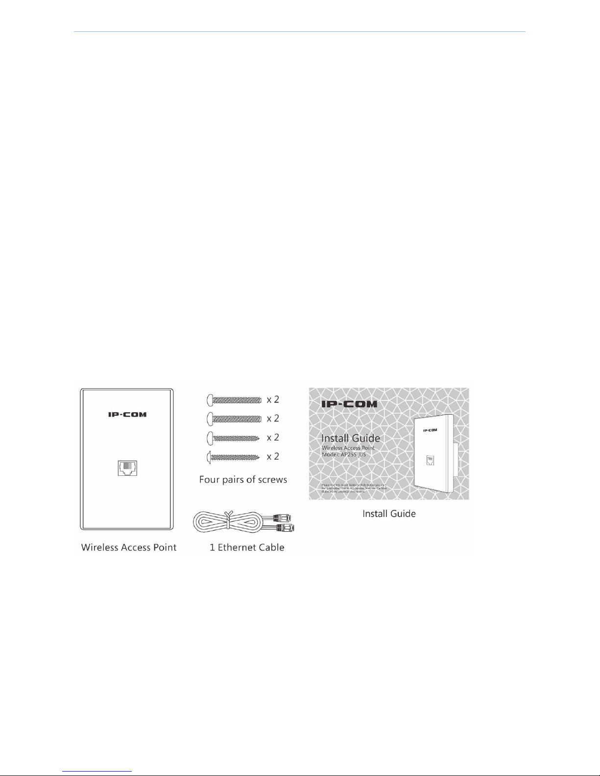
1.2 Package contents
Unpack the package. Your box should contain the following items:
If any item is incorrect, missing or damaged, please keep the original package and contact the vendor for
replacement immediately.
Page 7
Get to know the device
- 2 -
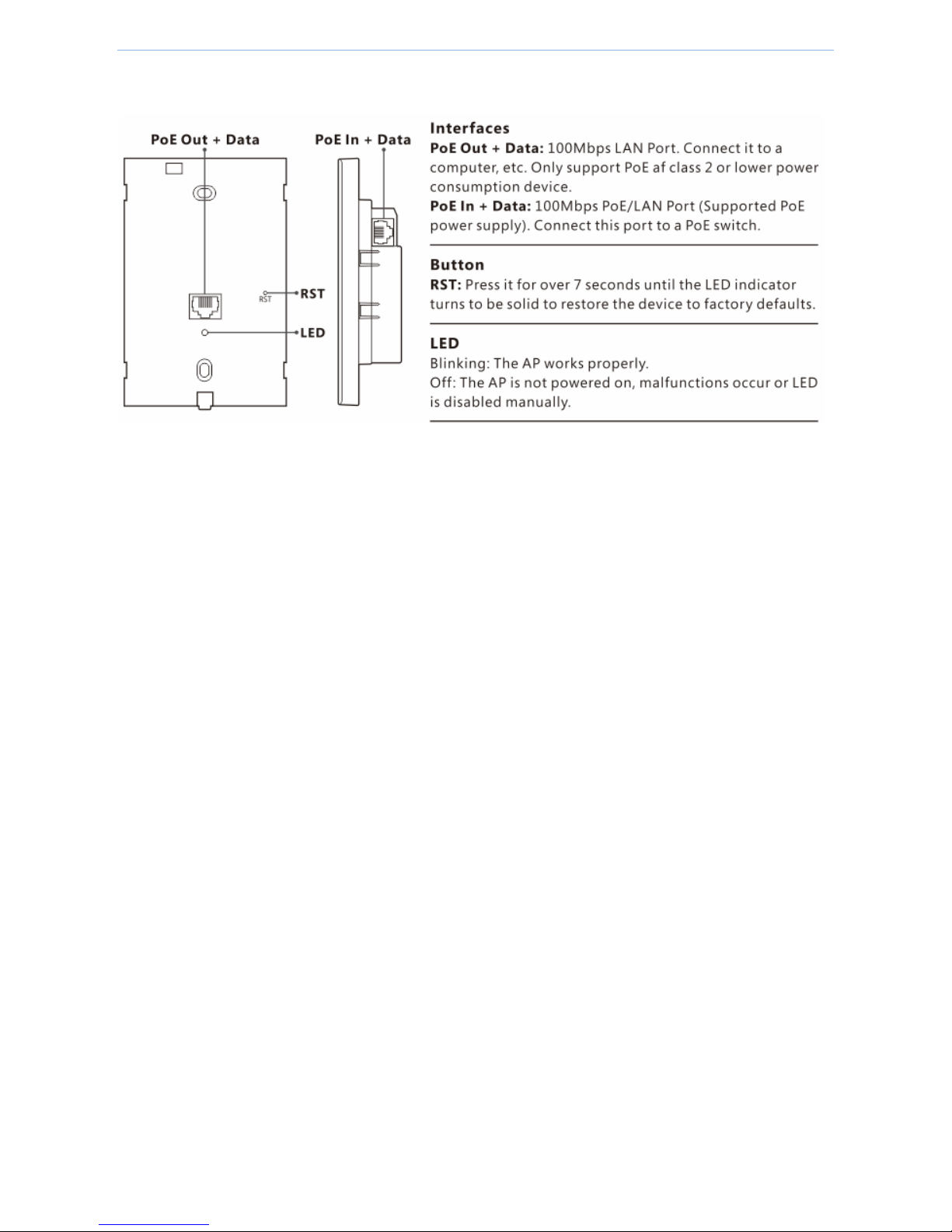
1.3 Hardware descriptions
Page 8
Device installation
- 3 -
02 Device installation
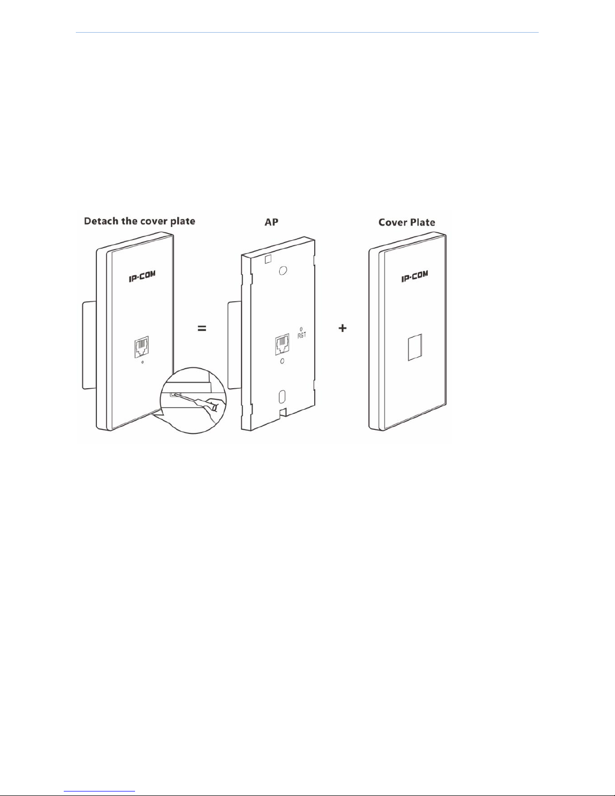
2.1 Install your device to a wall box
Before you install the device, make sure that an electrical wall box is installed and there’s an Ethernet cable
through the box.
1. Detach the device’s cover plate using a screw-driver.
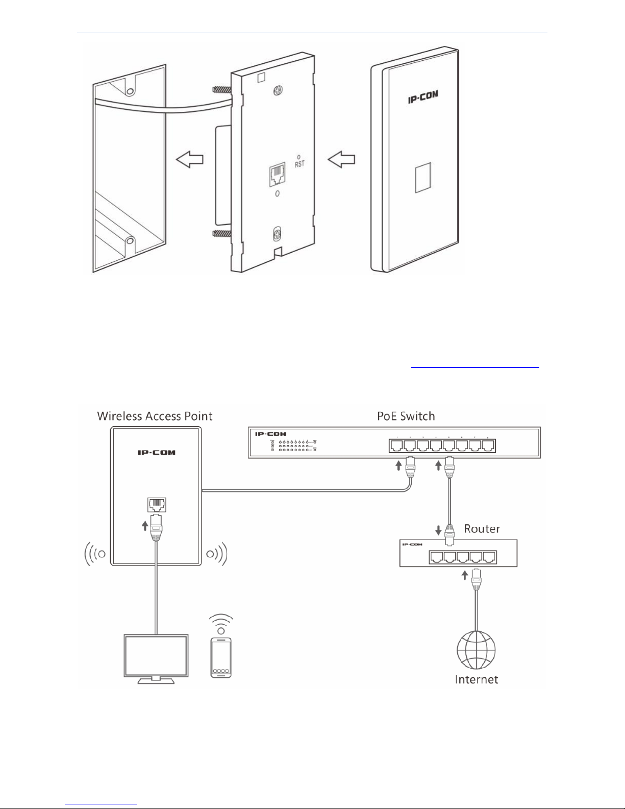
2. Connect the Ethernet cable in the wall box to the LAN port on the rear panel of the device.
3. Install the device in the wall box and verity that the Ethernet cable is positioned properly.
4. Fasten the device with the included screws. Adjust the screws to ensure that the device is flush with the wall
for proper fitting of the cover plate.
5. Attach the cover plate to the device.
Page 9
Device installation
- 4 -
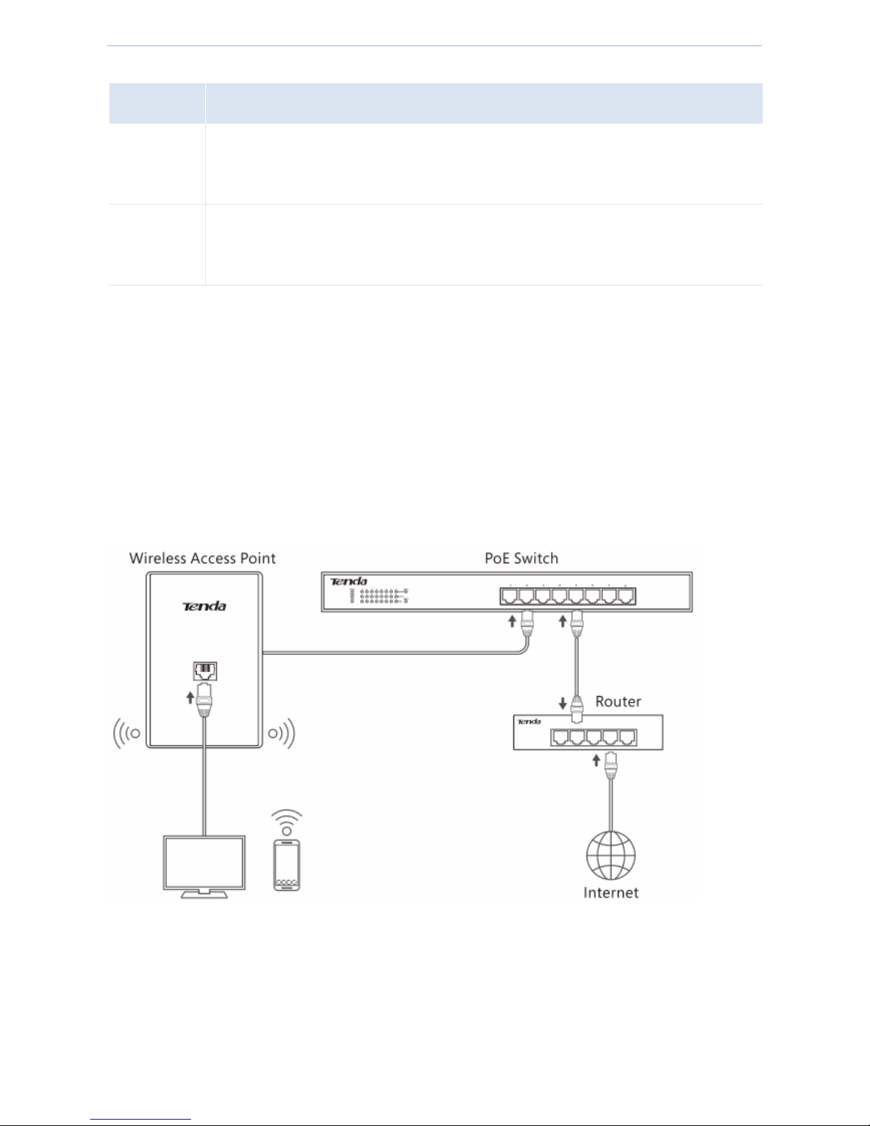
2.2 Connect your device to a network
1. Connect the other end of the Ethernet cable in the wall box to a PoE switch that is connected to the internet.
One end of the Ethernet cable in the wall box is connected to the device, see Install your device to a wall box.
2. Connect a computer to the LAN port on the front panel of the device.
Page 10
Web UI login
- 5 -
03 Web UI login
3.1 Web UI login
When using the device for the first time, or when you restore the device to factory default, you can log in to its
web UI via a browser with default login information. The default login information includes:
Item
Default Setting
IP Address
192.168.0.254
Username and Password
admin
To log in to this device:
(Assume that the device is in factory default state and ensure that your PC is connected to the device.)
1. Manually set up your PC’s IP address to 192.168.0.X (2~253), with a subnet mask of 255.255.255.0. (If the
switch and AP are in the same IP segment, make sure that the switch, AP and PC have different IP addresses).
For detailed steps, see Appendix Configure your computer.
Page 11

Web UI login
- 6 -
2. Launch a browser, enter the device’s default IP address 192.168.0.254 in the address bar, and press Enter.
We recommend that you use the browser of IE8 (or higher) or Google Chrome.
3. In the login page, enter admin (case sensitive) in both “Username” and “Password” box.
4. Click Login.
Then you come to the management page and can begin to configure the device.
Page 12
Web UI login
- 7 -
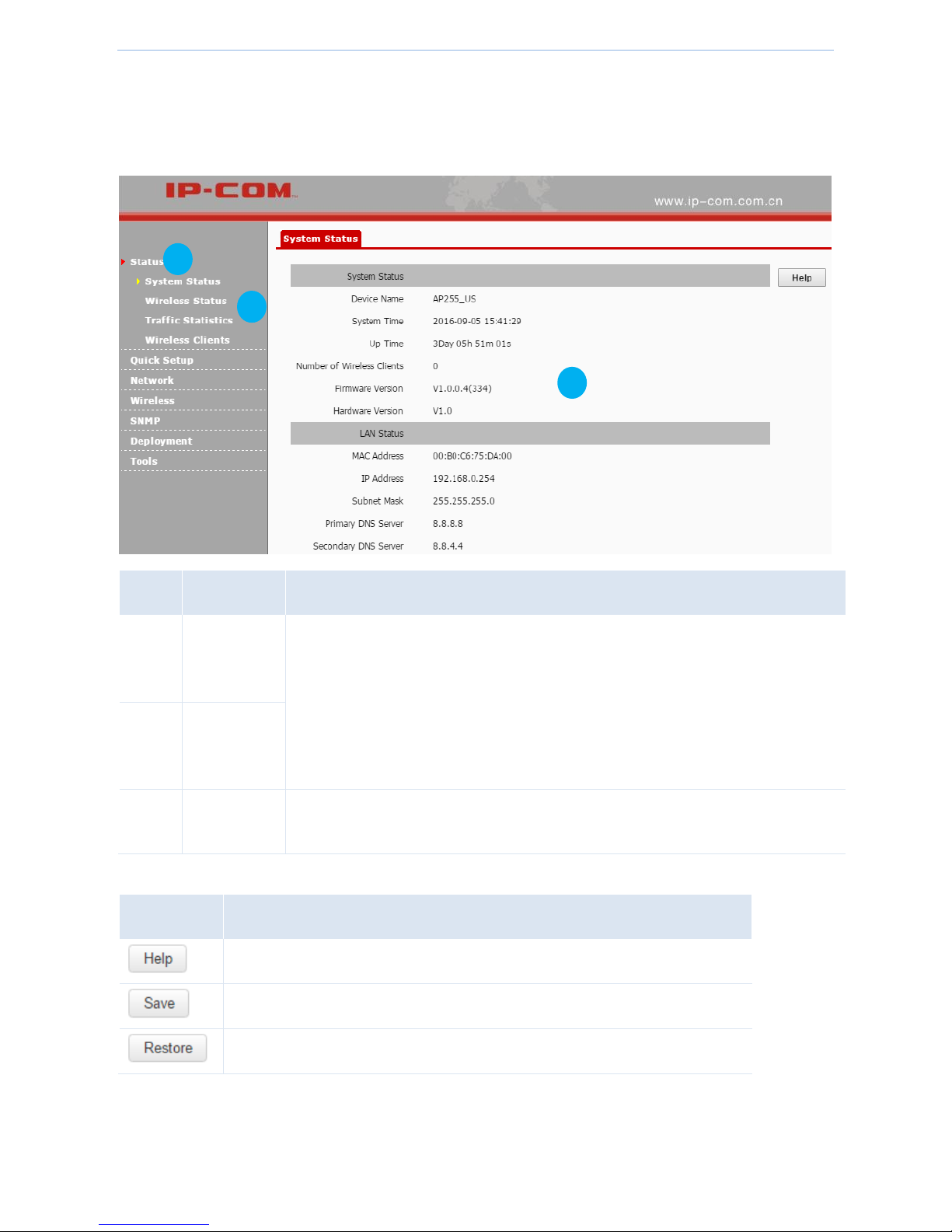
3.2 Web UI layout
This web UI is divided into three parts: primary navigation bar, secondary navigation bar and configuration area,
described as follows.
Item
Name
Description
❶
Primary
Navigation
bar
The navigation bar organizes the device’s menu of all functions in the form of a
navigation tree. You can choose the function menu from the navigation bar with
selection result shown in the configuration area.
❷
Secondary
Navigation
bar
❸
Configuration
area
The area is used to configure and view settings.
The following table shows the commonly used buttons of the web UI.
Item
Description
Click the button to view the help info if you meet any problems during the setup.
Click the button to apply your settings.
Click the button to clear the settings you are editing.
2
3
Page 13
Web UI functions
- 8 -
04 Web UI functions
4.1 Status
This part displays: System Status, Wireless Status, Traffic Statistics and Client List. If you have questions about
some parameters, click on the upper right corner of each page.
4.2 Quick Setup
This device supports the following operation modes and the default operation mode is AP mode.
AP mode
APClient mode
Page 14
Web UI functions
- 9 -
Operation mode description:
Work Mode
Description
AP mode
In this mode, the device connects to a network, such as the internet, using an Ethernet cable,
and transmits wireless signals. As a result, the device’s wireless clients can access the remote
network.
APClient
mode
In this mode, the device can wirelessly connect to a remote device, such as an AP, to extend the
remote wireless network, and transmits wireless signals. As a result, the device’s wireless
clients can access the remote network.
4.2.1 AP mode
In this mode, the device connects to a network, such as the internet, using an Ethernet cable, and transmits
wireless signals. As a result, the device’s wireless clients can access the remote network.
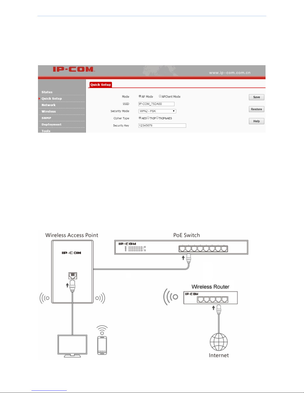
Application scenario
In the following application, the device connects to the internet using an Ethernet cable and transmits wireless
signals for wireless clients.
Configure AP mode
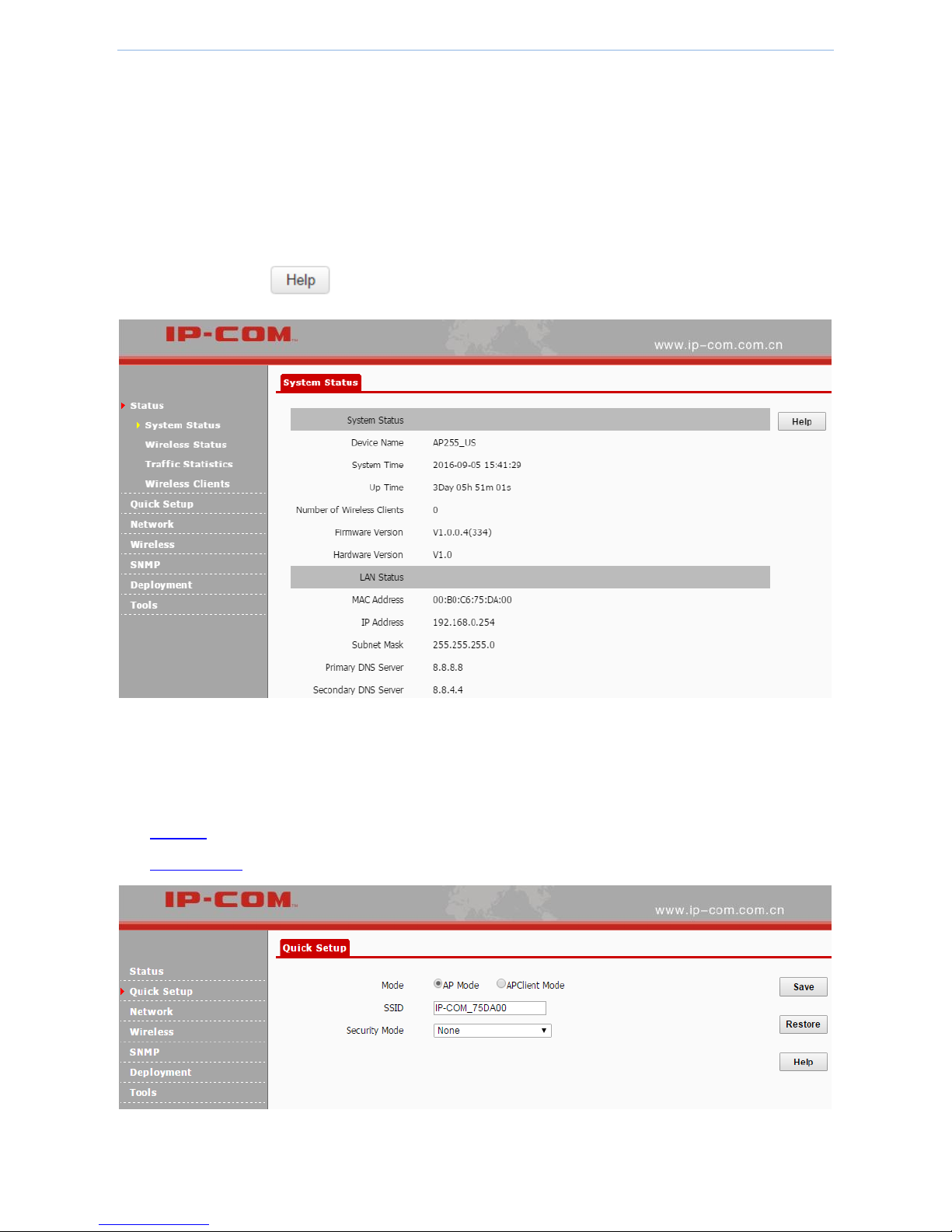
To configure AP mode:
1. Log in to the device’s web UI.
2. Go to Quick Setup, select AP Mode and set up the parameters.
Page 15
Web UI functions
- 10 -
1) SSID: Set up a wireless network name, such as IP-COM_75DA00.
This name is used for wireless clients to connect to the device.
2) Security Mode, Encryption Type: We recommend that you select WPA2-PSK, AES.
3) Security Key: Set up your WiFi password, such as 12345678.
3. Click Save to make these settings take effect.
4.2.2 APClient mode
In this mode, the device can wirelessly connect to a remote device, such as an AP, to extend the remote wireless
network, and transmits wireless signals. As a result, the device’s wireless clients can access the remote network.
Application scenario
In the following application, the device can’t connect to the wireless router using an Ethernet cable, but the
device needs to access the internet through the wireless router. In this case, you can configure your device to
work in APClient mode.
Page 16
Web UI functions
- 11 -
Assume that the wireless router’s info is as follows:
SSID
IP-COM_610220
WiFi Password
87654321
Configure APClient mode
To configure APClient mode:
1. Log in to the device’s web UI.
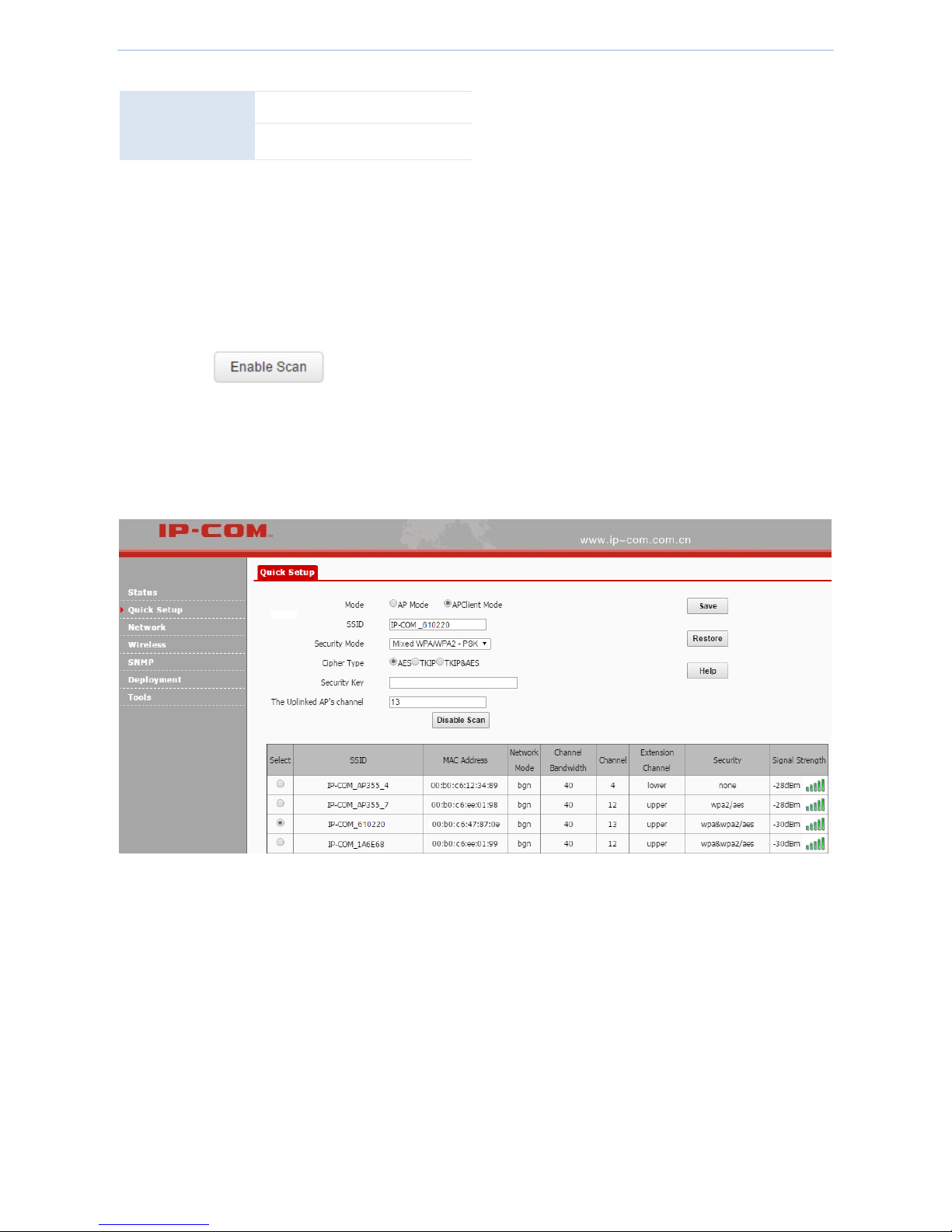
2. Go to Quick Setup, select APClient Mode and set up the parameters.
1) Click .
2) In the scanned list, select IP-COM_610220.
The SSID, Security Mode, Cipher Type and channel will be filled automatically.
3) In the Security Key field, enter 87654321.
3. Click Save to make these settings take effect.
Page 17
Web UI functions
- 12 -
4.3 Network
Network settings contain the following:
LAN Setup: On this page, you can set up LAN IP address, which is used to log in to the web UI and to
communicate with the local network.
DHCP Server: On this page, you can enable/disable and set up DHCP server parameters for the device’s
clients.
DHCP Client List: On this page, you can check how many DHCP clients are connected and each client’s IP
address, MAC address and lease time.
4.3.1 LAN Setup
On this page, you can set up LAN IP address, which is used to log in to the web UI and to communicate with the
local network. This device supports two methods to set up your LAN IP address:
Static IP: Set up LAN IP address manually
In this method, you need to manually set up LAN IP address. If you modified LAN IP address, when you log in
to the device’s web UI, please use the new IP address. If you change LAN IP segment, please change your
computer’s IP segment to the new one as well.
DHCP: Obtain LAN IP address from another DHCP server
In this method, the device can obtain LAN IP address from another DHCP server. In this way, it reduces IP
conflict and the cost of configuring IP address manually. If your device obtains LAN IP address from a DHCP
server of an uplink router and you don’t know the IP address, you can log in to the uplink router’s web UI to
check the obtained IP address.
Parameter description
Page 18

Web UI functions
- 13 -
Parameter
Description
MAC Address
This device’s MAC address of LAN port.
Address Mode
Select a method to set up the LAN IP address. The default method is Static IP.
Static IP: In this method, you need to manually set up LAN IP address. If you modified
LAN IP address, when you log in to the device’s web UI, please use the new IP address. If
you change LAN IP segment, please change your computer’s IP segment to the new one
as well.
Dynamic IP: In this method, the device can obtain LAN IP address from another DHCP
server. In this way, it reduces IP conflict and the cost of configuring IP address manually. If
your device obtains LAN IP address from a DHCP server of an uplink router and you don’t
know the IP address, you can log in to the uplink router’s web UI to check the obtained IP
address.
IP Address
It is used to log in to the device’s web UI and communicate with the local network. The
default one is 192.168.0.254.
Subnet Mask
It is used to determine IP segment of the IP address. The default one is 255.255.255.0
Gateway
It helps the device find a network route to connect to the internet or other networks.
Primary DNS
Server
Domain names, such as www.google.com, are easier to remember than IP addresses, such
as 93.46.8.89. A correct DNS server allows you to access websites using their domain names
instead of IP addresses.
Secondary DNS
Server
It is a backup DNS server address.
Device Name
Enter a distinct name for your device so that the administrator can manage the device from
a remote spot if necessary.
Ethernet Mode
Auto-negotiation: In this mode, it will transmit in a shorter distance with higher speed. In
general, it is recommended to select this option.
10M half-duplex: In this mode, it can transmit for a longer distance with lower speed.
When the distance between this device and the remote device are more than 100
meters, please select this option and ensure that the remote device works in auto
negotiation mode, or else the device’s LAN port can't send and receive data.
Static IP: Set up LAN IP address manually
In this method, you need to manually set up LAN IP address. If you modified LAN IP address, when you log in to
the device’s web UI, please use the new IP address. If you change LAN IP segment, please change your computer’s
IP segment to the new one as well.
Page 19

Web UI functions
- 14 -
To set up LAN IP address manually:
1. Log in to the device’s web UI.
2. Go to Network > LAN Setup.
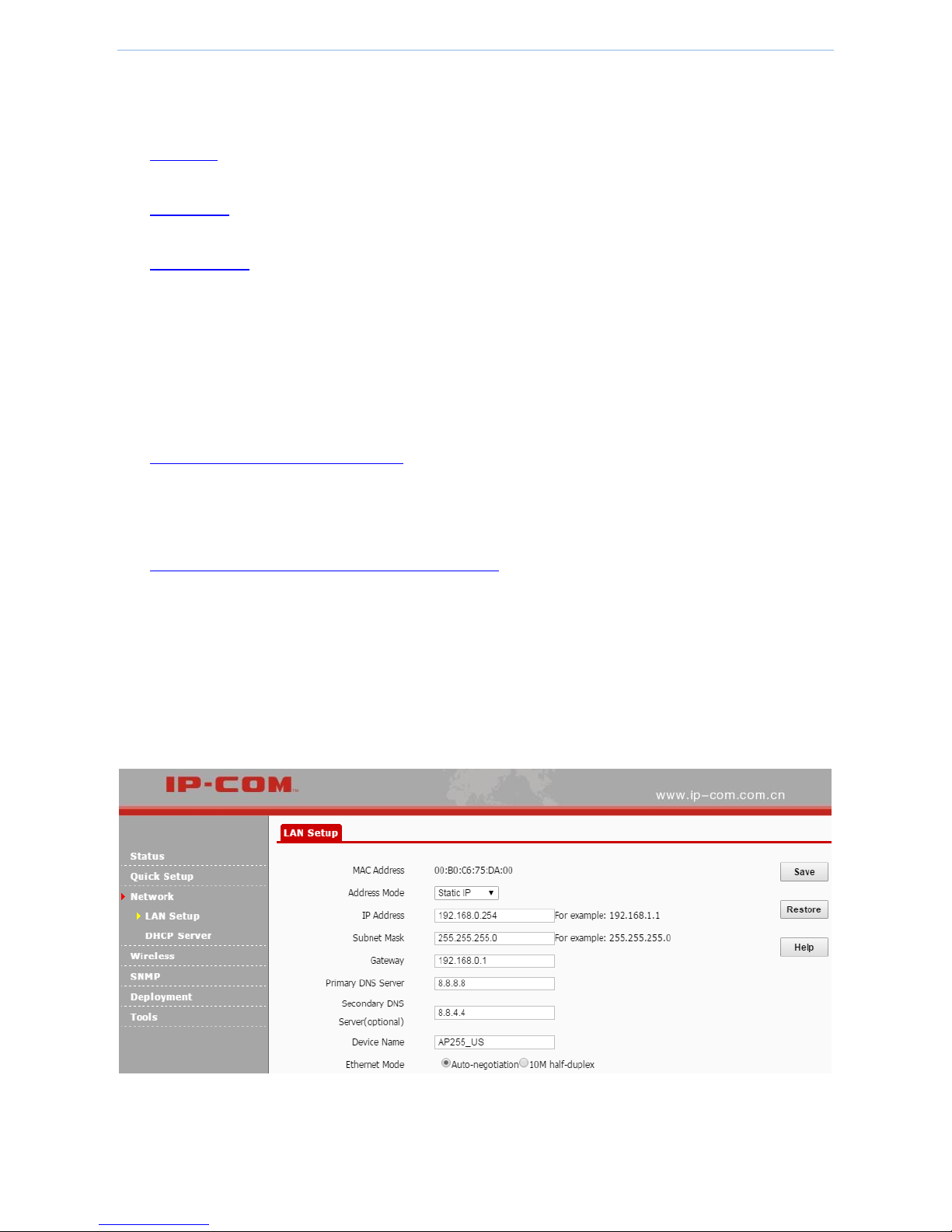
3. Set up LAN IP parameters.
1) Address Mode: Click the dropdown list and select Static IP.
2) IP Address: Enter a new IP address, such as 192.168.0.2.
3) Subnet Mask: Enter a subnet mask for the IP address, such as 255.255.255.0.
4) Gateway: Enter a gateway for the device so that the device can find a network route to connect to the
internet or other networks. Usually it’s the uplink router’s LAN IP address.
5) Primary DNS Server: Enter the primary DNS server address. If there is another backup DNS server, enter
it into Secondary DNS Server field.
A correct DNS server allows you to access websites using their domain names instead of IP addresses.
6) Device Name: Enter a distinct name for your device so that the administrator can manage the device
from a remote spot if necessary.
4. Click Save to make these settings take effect.
Page 20

Web UI functions
- 15 -
Dynamic IP: Obtain LAN IP address from another DHCP server
In this method, the device can obtain LAN IP address from another DHCP server. In this way, it reduces IP conflict
and the cost of configuring IP address manually. If your device obtains LAN IP address from a DHCP server of an
uplink router and you don’t know the IP address, you can log in to the uplink router’s web UI to check the
obtained IP address.
To obtain LAN IP address from another DHCP server:
1. Log in to the device’s web UI.
2. Go to Network > LAN Setup.
3. Address Mode: Click the dropdown list and select Dynamic IP.
4. Click Save to make these settings take effect.
4.3.2 DHCP Server
On this page, you can enable/disable and set up DHCP server parameters for the device’s clients.
Page 21

Web UI functions
- 16 -
Parameter description
Parameter
Description
DHCP Server
Enable/disable the device’s DHCP server. By default, it is enabled.
Start IP
The first IP address that can be assigned to a DHCP client. By default, it is 192.168.0.25400.
End IP
The last IP address that can be assigned to a DHCP client. By default, it is 192.168.2.200.
Subnet Mask
It is used to determine the IP segment of the DHCP server. By default, it is 255.255.255.0.
Gateway
It is assigned to DHCP clients so that they can find a network path to access the internet or
other networks. By default, it is 192.168.2.254.
Primary DNS
Server
Domain names, such as www.google.com, are easier to remember than IP addresses, such
as 93.46.8.89. A correct DNS server allows you to access websites using their domain names
instead of IP addresses.
Secondary DNS
Server
It is a backup DNS server address.
Lease Time
When a DHCP client obtains IP address, the DHCP server will assign a certain lease time to
the client's IP address. If a DHCP client wants to use the IP address continuously, when the
lease time goes to 50%, the DHCP client will transmit a unicast DHCP request to the DHCP
server. If the DHCP client gets no response from the DHCP server, it will continue to transmit
a unicast DHCP request to the DHCP server when the lease time goes to 7/8. If it fails again,
when the lease time goes to 100%, the IP address will be released and might be used by
other DHCP clients.
Configure DHCP server
Note
If more than one DHCP server exists in the same network, to avoid IP conflict, make sure the IP pool of each DHCP
server doesn’t overlap.
To configure DHCP server:
1. Log in to the device’s web UI.
2. Go to Network > DHCP Server.
3. Set up DHCP server parameters.
1) DHCP Server: Check the box of Enable.
Page 22

Web UI functions
- 17 -
2) Start IP/End IP: Enter the first and last IP address of the DHCP IP pool.
3) Subnet Mask: Enter a subnet mask for the DHCP server.
4) Gateway: Enter a gateway which is assigned to DHCP clients.
5) Primary/Secondary DNS Server: Enter a primary DNS server address for DHCP clients. If there is another
DNS server, please enter it into the Secondary DNS Server field.
4. Click Save to make these settings take effect.
4.3.3 DHCP Client List
On this page, you can check how many DHCP clients are connected and each client’s IP address, MAC address and
lease time.
To enter DHCP Client page:
1. Log in to the device’s web UI.
2. Go to Network > DHCP Server > DHCP Client.
4.4 Wireless
Wireless settings contain the following:
Basic: On this page, you can set up basic wireless parameters of this device, such as SSID, broadcast SSID,
encryption type, and so on.
Radio: On this page, you can set up radio parameters of the device, such as country, network mode, channel,
and so on.
Channel Scan: On this page, you can scan wireless signals surrounding the area and see some of their
information, such as SSID, channel. According to the information, you can select a channel that is less used
for your device.
Advanced: On this page, you can set up advanced wireless parameters of this device. You can keep the
default value if you’re not familiar with these parameters.
Access Control: On this page, you can set up rules to forbid or permit specified wireless clients to connect to
this device. The rules are based on MAC address.
Page 23

Web UI functions
- 18 -
QVLAN: On this page, you can enable/disable and set up VLAN parameters. With this device and a switch
with QVLAN function, you can manage different wireless network.
4.4.1 Basic
On this page, you can set up basic wireless parameters of this device, such as SSID, broadcast SSID, encryption
type, and so on.
Parameter description
As the device provides lots of wireless parameters, to help you understand these parameters, we devide them into
several parts, shown as below.
Commonly used parameters description
Parameter description of WEP
Parameter description of WPA-PSK, WPA2-PSK and mixed WPA/WPA2-PSK
Parameter description of WPA and WPA2
Commonly used parameters description
Parameter
Description
SSID
Select a SSID to be modified. This device supports two SSIDs.
Enable
Enable or disable the selected SSID.
Broadcast SSID
Enable or disable broadcast SSID function.
Enable: the device broadcasts its SSID and the SSID is displayed in the network list of clients
that support 5G.
Disable: the device does not broadcast its SSID and the SSID is not displayed in the network
list of clients that support 5G. When a client want to connect to the device, the client needs
to manually enter the correct SSID name.
AP Isolation
Enable: Wireless clients that connect to the SSID can't communicate with each other.
Disable: Wireless clients that connect to the SSID can communicate with each other.
WMF
It is used to optimize multicast situation. After you enable this function, only the actual
receivers can obtain corresponding packets. It saves wireless bandwidth and provides a more
secure and reliable network.
Client limit
Set up the maximum number of wireless clients allowed to connect to the SSID. When the
amount of wireless clients reaches this value, any new client can’t connect to the SSID unless
some connected clients disconnect from the SSID.
Page 24

Web UI functions
- 19 -
SSID
The wireless name of the device. To better recognize your wireless network, we recommend
that you modify the SSID name.
Chinese SSID
Encode
UTF-8 is an international encoding standard. GB2312 is a Chinese encoding standard.
Security Mode
Set up the wireless security mode. None means allowing any client to connect to the device.
This device supports WEP, WPA-PSK, WPA2-PSK, Mixed WPA/WPA2-PSK, WPA and WPA2, for
details, refer to
Parameter description of WEP
Parameter description of WPA-PSK, WPA2-PSK and mixed WPA/WPA2-PSK
Parameter description of WPA and WPA2
Security mode description:
Parameter description of WEP
WEP (Wired Equivalent Privacy). A static key is used to encrypt all data, providing a security level equal to wired
LAN encryption. The wireless rate can be up to 54Mbps.
Parameter
Description
Encryption
Type
This device supports the following types.
Open: In Open System authentication, the WLAN client need not provide its credentials to
the Access Point during authentication. Any client can authenticate with the Access Point
and then attempt to associate. In effect, no authentication occurs. Subsequently WEP keys
can be used for encrypting data frames. At this point, the client must have the correct keys.
Shared: In a shared authentication, the WLAN client needs to provide its credentials to the
Access Point during authentication.
802.1x: In 802.1x authentication, the device needs to negotiate with the radius server first,
then the device’s wireless clients need to use the radius username and password to finish
802.1x authentication.
Default Key
Once you select a certain key, such as key 1, wireless clients must use the same key, key 1, to
connect to your device.
For WEB security mode, most smart phones only support key 1, so we recommend that you
select key 1 of this device.
ASCII
Enter a WEP key. The length of the character string is a 5 or 13.
HEX
Enter a WEP key. The length of the character string is 10 or 26.
RADIUS Server
Enter the radius server IP address for authentication.
Page 25

Web UI functions
- 20 -
RADIUS Port
Enter the authentication port of the radius server.
RADIUS
Password
Enter the shared key of the radius server.
Parameter description of WPA-PSK, WPA2-PSK and mixed WPA/WPA2-PSK
It is designed for home and small office networks and doesn't require an authentication server. Each WLAN
network device encrypts the network traffic using a 256 bit key. This key may be entered either as a string of 64
hexadecimal digits, or as a passphrase of 8 to 63 printable ASCII characters. If ASCII characters are used, the 256
bit key is calculated by applying the PBKDF2 key derivation function to the passphrase, using the SSID as the salt
and 4096 iterations of HMAC-SHA1.
Parameters
Description
Cipher Type
Select WPA encryption type.
AES: AES is short for Advanced Encryption Standard. This encryption algorithm ensures a
higher wireless rate.
TKIP: TKIP is short for Timing Key Integrity Protocol. Wireless rate can only reach 54Mbps
with this algorithm.
TKIP&AES: Compatible with TKIP and AES. The wireless client can use either AES or TKIP
algorithm to connect to the WiFi.
Key
Enter a security key that is either 8 - 63 ASCII characters or 8 - 64 Hex characters.
Key Update
Interval
You can configure security key's update interval here within the range from 60 to 99999
seconds. If set to 0, the key will not be updated.
Parameter description of WPA and WPA2
WPA is opposed to WPA-PSK and is also referred to as WPA-802.1X mode. It is designed for enterprise networks
and requires a RADIUS authentication server. This requires a more complicated setup, but provides additional
security (e.g. protection against dictionary attacks on short passwords). Various kinds of the Extensible
Authentication Protocol (EAP) are used for authentication. WPA-Enterprise mode is available with both WPA and
WPA2.
Parameters
Description
RADIUS Server
Enter the radius server IP address for authentication.
RADIUS Port
Enter the authentication port of the radius server.
RADIUS
Password
Enter the shared key of the radius server.
Page 26

Web UI functions
- 21 -
Configure basic wireless parameters
To configure basic wireless parameters:
1. Log in to the device’s web UI.
2. Go to Wireless > Basic.
3. Set up basic wireless parameters.
1) SSID: Modify the device’s SSID.
2) Security Mode, Cipher Type, Key: We recommend that you select WPA2-PSK and AES and set up a WiFi
password (Key). For more information, please refer to Security Method Description.
3) Other parameters: If not specified, you can keep the default value.
4. Click Save to make these settings take effect.
4.4.2 Radio
On this page, you can set up radio parameters of the device, such as country, network mode, channel, and so on.
Parameters description
Parameter
Description
Enable Wireless
Enable/Disable the device’s wireless signal.
Country
Select a country that your device is operating.
Network Mode
Select an 802.11 network mode. By default the device works at 11ac mode.
Page 27

Web UI functions
- 22 -
11a mode: Clients that support 11a network mode can connect to the device. The
wireless speed can be up to 54Mbps.
11a/n mode: Clients that support 11a or 11n network mode can connect to the device.
The wireless speed can be up to 150Mbps.
11ac mode: Clients that support 11ac network mode can connect to the device. The
wireless speed can be up to 433Mbps.
Channel
Click the dropdown list and select a wireless channel. To avoid channel conflict, please select
a channel that is less used in surrounding area. You can go to Wireless > Site Survey to check
each channel’s usage.
Channel
Bandwidth
20: This device can only use 20MHz bandwidth.
40: This device can only use 40MHz bandwidth.
80: This device can only use 80MHz bandwidth.
Extension
Channel
It is used to determine the AP’s channel range when bandwidth is 40.
Channel Lockout
If you check this box, you can’t modify country, network mode, channel, channel bandwidth
and extension channel.
AP isolation
Enable: Wireless clients that connect to the SSID can't communicate with each other.
Disable: Wireless clients that connect to the SSID can communicate with each other.
WMM Capable
WMM is a wireless QoS protocol designed to preferentially transmit packets with high
priority, thus guaranteeing better QoS services for voice and video applications in a WLAN
network.
APSD Capable
APSD (Automatic Power Save Delivery) is disabled by default.
Ageing Time
After a client connects to the device:
If there is no data transmission within the time period, the device will actively disconnect
the client.
If data transmission is detected within the time period, the device will recalculate the
time age.
Page 28

Web UI functions
- 23 -
Configure wireless radio parameters
To configure wireless radio parameters:
1. Log in to the device’s web UI.
2. Go to Wireless > Radio.
3. Set up the parameters.
1) Channel Lockout: Uncheck the box so that you can modify the country.
2) Country: Select a country that your device is operating.
3) Channel Click the dropdown list and select a wireless channel. To avoid channel conflict, please select a
channel that is less used in surrounding area. You can go to Wireless > Site Survey to check each
channel’s usage.
4) Other parameters: If not specified, you can keep the default value.
4. Click Save to make these settings take effect.
Page 29

Web UI functions
- 24 -
4.4.3 Channel Scan
On this page, you can scan wireless signals surrounding the area and see some of their information, such as SSID,
channel. According to the information, you can select a channel that is less used for your device.
To start scanning signals:
1. Log in to the device’s web UI.
2. Go to Wireless > Site Survey.
3. Click .
Wait a moment and the results will be displayed on the page, as shown in the figure below. Drag the scroll bar to
see more wireless signals.
According to the wireless signals, to reduce the channel interference, you can select a channel that is less used
surrounding the area for your device.
Page 30

Web UI functions
- 25 -
4.4.4 Advanced
On this page, you can set up advanced wireless parameters of this device. You can keep the default value if you’re
not familiar with these parameters.
Parameter description
Parameter
Description
Beacon Interval
Set up an interval for sending beacon frames. The range is 20~999ms.
Beacon frames are transmitted at a regular interval to allow mobile clients to join the
network. Beacon frames are used for a client to identify nearby APs. In general, the
smaller the value is, the quicker a wireless client can connect to the AP. the larger the
value is, the higher the data transmission of the WLAN network’s efficiency is.
Fragment Threshold
Set up the maximum length of frames that can be transmitted without fragmentation.
The range is 256~2346 bytes.
Fragmentation means to fragment a large frame into small pieces, with each piece
transmitted and acknowledged separately. When the length of a frame exceeds the
specified fragment threshold value, it is fragmented.
A longer frame is less likely to be successfully received. Therefore, in a WLAN where
there is high error rate, you can decrease the fragment threshold to increase frame
transmission reliability.
In a WLAN network with no interference, we recommend that you increase the
Fragment Threshold to improve the data transmission throughput by decreasing the
ACK times.
RTS Threshold
Set up the threshold length for RTS/CTS mechanism.
RTS/CTS frames occupy a certain network bandwidth so that only the frames larger
than RTS/CTS threshold will enable RTS/CTS mechanism to avoid data sending collisions
in a WLAN network. The RTS/CTS threshold range is 1~2347 bytes.
You need to set up a rational value: A small value causes RTS packets to be sent more
often, thus consuming more of the available bandwidth. However, the more often RTS
packets are sent, the quicker the system can recover from interference or collisions. We
recommend that you set up a small value in a high-density WLAN network to decrease
the probability of collision.
DTIM Interval
Set up the number of beacon intervals between Delivery Traffic Indication Message
(DTIM) transmissions. The range is 1~255 Beacon interval.
The AP sends buffered broadcast/multicast frames with the configured DTIM interval.
For example, if you set DTIM to 2, the AP will send buffered broadcast/multicast frames
every two Beacon intervals.
Receive Signal
Define the minimum client signal level accepted by the device. If a wireless client’s
Page 31

Web UI functions
- 26 -
strength
signal is lower than this value, the client cannot connect to the device.
TX Power
Set up the device’s wireless transmission power.
Power Lockout
If you check this box, you can’t modify the value of TX Power.
Preamble
Mainly used for preamble synchronization. It is advisable to keep the default value
unchanged.
Configure advanced wireless parameters
To configure advanced wireless parameters:
1. Log in to the device’s web UI.
2. Go to Wireless > Advanced.
3. Set up advanced wireless parameters.
We recommend that you keep the default value if you are not familiar with these parameters.
4. Click Save to make these settings take effect.
Page 32

Web UI functions
- 27 -
4.4.5 Access control
On this page, you can set up rules to forbid or permit specified wireless clients to connect to this device. The rules
are based on MAC address.
Parameter descriptions
Parameter
Description
SSID
Select a SSID to perform this function.
Filter Mode
Disable: Disable access control function.
Allow: The device permits wireless users that correspond to the added MAC addresses to
connect to the device. Other users are not allowed to connect.
Deny: The device forbids wireless users that correspond to the added MAC addresses to
connect to the device. Other users are allowed to connect.
MAC Address
Manually enter MAC addresses of wireless users that are forbidden or permitted to connect
to the device.
To make a MAC address effective to be forbidden or permitted, click this button to add the
entered MAC address to the following list.
Configure access control function
There are three commonly used situations:
When you want to forbid or permit some wireless users that are not connected to the device
When you want to forbid or permit some wireless users that are connected to the device
If you want to delete a wireless user from the access control rule
When you want to forbid or permit some wireless users that are not connected to the device, do as follows:
1. Log in to the device’s web UI.
2. Go to Wireless > Access Control.
3. Set up the access control rule.
1) SSID: Select a SSID to perform this function.
2) MAC Filter Mode: Select an option. For example, if you want to forbid certain wireless users to connect
to this device, please select Deny.
3) MAC Address: In the second table, enter a MAC address that is forbidden or permitted to connect, such
as AA:AA:AA:AA:AA:AA.
4) Click Add. The MAC address goes into the following list.
Page 33

Web UI functions
- 28 -
4. Click Save to make these settings take effect.
When you want to forbid or permit some wireless users that are connected to the device, do as follows:
1. Log in to the device’s web UI.
2. Go to Wireless > Access Control.
3. Set up the access control rule.
1) SSID: Select a SSID to perform this function.
2) MAC Filter Mode: Select an option. For example, if you want to forbid certain wireless users to connect
to this device, please select Deny.
3) In the first table, if you want to deny or allow a wireless client, click Add of the item. The wireless client’s
MAC address goes into the third table.
4. Click Save to make these settings take effect.
If you want to delete a wireless user from the access control rule, click Delete and follow on-screen
instructions.
Page 34

Web UI functions
- 29 -
4.4.6 QVLAN
On this page, you can enable/disable and set up VLAN parameters. With this device and a switch with QVLAN
function, you can manage different wireless network.
Parameter description
Parameter
Description
Enable
Enable of disable VLAN function of the device.
PVID
It’s the default VLAN ID of the trunk port. When VLAN-untagged packets arrive at the trunk
port, the trunk port marks the PVID as a tag to the packets.
Management
VLAN
Set up this device’s management VLAN ID. By default it is 1.
After the management VLAN is modified, only when the management computer is in the same
VLAN can it access this device’s web UI.
Trunk Port
This device’s trunk port allows all VLANs to get through. Port 0 is on the rear panel and port 1
is on the front panel.
Wired LAN
Port
Set up VLAN ID of the available wired LAN port(s). When a port is set to a trunk port, it is not
available to be set a certain VLAN ID.
2.4G SSID
Set up VLAN ID of the listed SSIDs. By default it is 1000. The range is 1 ~ 4094.
After you set up a VLAN ID for a SSID, the SSID only allows tagged packets in the same VLAN or
untagged packets to get through.
The detailed receiving and sending procedures on each type of port are described as below:
Port Type
Procedures on receiving packets
Procedures on sending packets
Tagged packets
Untagged packets
Access port
Tagged packets are
forwarded to other ports
with the same VLAN ID
as the tagged packets.
Untagged packets are
forwarded to other ports
with the same VLAN ID
as the PVID of the
receiving port.
Delete the packets’ tag and send the
packets to a network device that
doesn’t support VLAN function.
Trunk port
VLAN ID = PVID, delete tag and send.
VLAN ID ≠PVID, keep tag and send.
Page 35

Web UI functions
- 30 -
Application scenario
In the following application, employees in the hotel can only connect to SSID1 to access the server, guests of the
hotel can only connect to SSID2 to access the internet, but the administrator can access both the server and the
internet. In this case, we can set up VLAN 10 for SSID1 and the server, VLAN 20 for SSID2 and the router, and VLAN
30 for the administrator, the server and the router.
Note that the server and the router in this application must support QVLAN function. If not, you need to add a
layer 3 switch to achieve the requirements.
Configure VLAN function
To achieve the requirements, you need to configure the following devices.
Configure this device
Configure the PoE switch
Configure the server
Configure the router
Configure this device:
1. Log in to the device’s web UI.
2. Go to Wireless > Basic. Enable both two SSIDs, and modify the two SSID name to IP-COM_1 and IP-COM_2
respectively.
Page 36

Web UI functions
- 31 -
3. Go to Wireless > QVLAN, and set up the parameters.
1) Enable: Check the box to enable QVLAN function.
2) PVID: Keep the default value 1.
3) Management VLAN: Keep the default value 1.
4) Trunk Port: Only select port0.
5) LAN1 Port: Enter 30.
6) IP-COM_1: Enter 10.
7) IP-COM_2: Enter 20.
8) Click Save to make these settings take effect.
Page 37

Web UI functions
- 32 -
Configure the PoE switch:
Switch Port
Allowed VLAN ID
Port Type
PVID
Connect to this device
1, 10, 20, 30
Trunk port
1
Connect to the server
1,10, 30
Trunk port
1
Connect to the router
1,20, 30
Trunk port
1
Configure the server:
The port connecting to the PoE switch should allow VLAN 10 and VLAN 30 to get through.
Configure the router:
The port connecting to the PoE switch should allow VLAN 20 and VLAN 30 to get through.
4.5 SNMP
SNMP (Simple Network Management Protocol) is now the most widely used network management protocol on
TCP/IP network. Through SNMP, A NMS (Network Management Station) can remotely manage all SNMP agents,
including monitoring network status, modifying network device, receiving network alarm events, and so on.
Regardless of different devices’ physical feature, SNMP can achieve automation management of devices from
different manufactories, which is especially suitable for small-scale, high-speed and low-cost network.
Parameter description:
Parameter
Description
SNMP
Enable or disable this function.
Administrator Name,
Device Name,
Location
For these three parameters, please enter their actual values. These parameters are
only used for the SNMP host to recognize this device. When this device and the SNMP
host start to negotiate, they don’t need the three parameters.
Read Community
It is used to negotiate with the SNMP host, that is to say, this parameter on both the
device and the SNMP host must be the same. The default is public.
Page 38

Web UI functions
- 33 -
Read/Write
Community
It is used to negotiate with the SNMP host, that is to say, this parameter on both the
device and the SNMP host must be the same. The default is private.
4.6 Tools
System tools contain the following contents:
Firmware Upgrade: Through this function, the device obtains a higher firmware version.
Time & Date: To make time-related function, such as Logs and Time Reboot, work properly, you must ensure
that the device’s system time is correct. Through this section, you can synchronize the device’s time with the
internet or manually set up the time. Besides, you can set up login timeout period, during which if you don’t
have any configuration on the web UI you need to login again.
Logs: Through this section, you can view the device’s logs, and add log servers to receive the logs.
Configuration-Backup & Restore: On this page, you can backup and restore the existing configurations so that
when your device’s performance goes down because of improper configuration, or after you restore the
device to factory default, you can restore your device to a previous working configuration.
Configuration-Restore to Factory Default: When you forget the login username, password or IP address, or
when you have problems of accessing the internet but can’t find a solution, you can restore the device to
factory default.
Administrator: On this page, you can modify the administrator or common user’s login username and
password, and can delete the common user account.
Diagnostics-Ping: Ping is a commonly used diagnosis and troubleshooting command. It can detect whether
the device is reachable to a specified IP address or domain name. If it is reachable, the destination IP address
returns response packets.
Reboot: When your device has worked for a long time, we recommend that you reboot the device to make it
work faster.
Time Reboot: It is used to reboot device circularly or regularly.
LED: If the LED light disturbs you, you can disable the LED on this page.
Uplink Detection: On this page, you can circularly detect whether the device is reachable to the specified
hosts. If the device loses its uplink connectivity, it forces the clients to re-associate with another device by
disabling SSID broadcast function.
Page 39

Web UI functions
- 34 -
4.6.1 Firmware Upgrade
Through this function, the device obtains a higher firmware version. If the device runs normally, we don’t
recommend that you perform firmware upgrade.
To upgrade a firmware for the device:
Note
Do not disconnect the power supply during the upgrade process, otherwise it may cause damage to the AP! In
case of sudden power failure, re-upgrade firmware. If you cannot enter the web UI after a sudden power failure,
contact our technical support, see Technical support.
1. Go to http://www.ip-com.com.cn to download the latest version of the firmware of the device.
2. Decompress the downloaded file using a decompress software and place it in a corresponding directory.
3. Log in to the device’s web UI.
4. Go to Tools > Firmware Upgrade.
5. Click Choose File (different characters may be displayed for different browses) to load the decompressed
upgraded software.
6. Click Upgrade and perform operations according to the prompt on the page.
After the progress bar is over, enter this page to view the displayed Current Firmware Version, judging that the
firmware is successfully upgraded.
Page 40

Web UI functions
- 35 -
4.6.2 Time & Date
To make time-related function, such as Logs and Time Reboot, work properly, you must ensure that the device’s
system time is correct. Through this section, you can synchronize the device’s time with the internet or manually
set up the time. Besides, you can set up login timeout period, during which if you don’t have any configuration on
the web UI you need to login again.
Synchronize system time with the internet
Manually set up system time
Page Timeout
Note
Time information will be lost after power failure of the AP. If Synchronized with the internet is enabled, after the
device is started and connected to the internet, it will resynchronize correct time from the internet.
Synchronize system time with the internet
The method for getting AP system time is synchronized with the internet by default. To ensure correct system time,
the AP will automatically calibrate its system time towards the time server on the internet every time slot set in
Sync Interval.
To synchronize system time with the internet:
1. Log in to the device’s web UI.
2. Go to Tools > Time & Date.
3. Check the box of Sync with Internet time servers.
4. Sync Interval: Select a time interval. You can keep the default value.
5. Time Zone: Select a time zone in your region.
6. Click Save to finish settings.
After the device is successfully connected to the internet, the system will get standard GMT time from the
internet.
Page 41

Web UI functions
- 36 -
Manually set up system time
If your device is not connected to the internet, you can use this method. Make sure your PC’s time is correct.
To manually set up system time:
1. Log in to the device’s web UI.
2. Go to Tools > Time & Date.
3. Uncheck the box of Sync with Internet time servers.
4. Click Sync with Your PC.
5. Click Save to finish settings.
Page 42

Web UI functions
- 37 -
Page Timeout
On this page, you can set up login timeout period, during which if you don’t have any configuration on the web UI
you need to login again.
4.6.3 Logs
Through this section, you can view the device’s logs, and add log servers to receive the logs. To make this function
work properly, go to Tools > Time & Date to make sure your device’s system time is correct.
Page 43

Web UI functions
- 38 -
View Logs
Log Se
View Logs
On this page, you can view the device’s system logs.
Refresh: If you want to see the latest logs, click Refresh.
Clear: If you think that the logs displayed are not helpful, click Clear.
Log Setup
On this page, you can add log servers to receive the logs. In this way, you can see the logs on the log server instead
of on the web UI.
Number of Logs: It is used to set up how many pieces of logs can be displayed on page View Logs.
To add a log server:
1. Log in to the device’s web UI.
2. Go to Tools > Logs > Log Setup.
3. Enable: Check this box to enable log server function.
4. Click Save.
Page 44

Web UI functions
- 39 -
5. Click Add.
6. On the pop-up window, set up the parameters.
1) Log Server IP: Enter an IP address that receives the device’s logs.
2) Log Server Port: Enter the log server’s port.
Make sure that this port on the device and the log server must be the same.
3) Enable: Check the box to enable the added log server.
4) Click Save.
4.6.4 Configuration-Backup & Restore
On this page, you can backup and restore the existing configurations so that when your device’s performance goes
down because of improper configuration, or after you restore the device to factory default, you can restore your
device to a previous working configuration.
To backup configurations
To restore configurations
To backup configurations:
1. Log in to the device’s web UI.
2. Go to Tools > Configuration > Backup & Restore.
Page 45

Web UI functions
- 40 -
3. Click Backup.
4. On the pop-up window, click OK.
To restore configurations:
1. Log in to the device’s web UI.
2. Go to Tools > Configuration > Backup & Restore.
3. Click Choose Flie and choose and load the device backup file.
4. Click Restore, and perform operations by referring to the prompt in the computer, and wait until the progress
bar is over.
4.6.5 Configuration-Restore to Factory Default
When you forget the login username, password or IP address, or when you have problems of accessing the
internet but can’t find a solution, you can restore the device to factory default.
Note
Reset to Factory Defaults means that all previous settings will be lost and the AP must be reset.
Ensure the device power supply is normal in the process of Reset to Factory Defaults.
You can restore the device to factory default by the following methods:
Using web UI
Using RST button
After you restore your device to factory default, you can use the following default value to log in to the web UI:
Default login IP address: 192.168.0.254
Page 46

Web UI functions
- 41 -
Default user name and password: admin
Using web UI:
1. Log in to the device’s web UI.
2. Go to Tools > Configuration > Restore to Factory Default.
3. Click Restore to Factory Default and follow on-screen instructions.
Using RST button:
If you forget the login username, password or IP address, you can use RST button to restore your device to factory
default, do as follows.
In power-up state, open the device cover, press and hold the button for 15s and then release it.
4.6.6 Username & Password
On this page, you can modify the administrator or common user’s login username and password, and can delete
the common user account. To prevent others from using the default login information to enter the web UI to
modify configurations, we strongly recommend that you modify the login user name and password.
This device supports two account types: administrator and user.
Administrator: This account has all authorities to manage the device. Both the user name and password are
admin.
User: This account can only view the configurations and cannot modify any configurations. Both the user name
and password are user.
To change the administrator or the user’s login information:
1. Log in to the device’s web UI.
2. Go to Tools > Administrator.
3. On the corresponding item, click Change.
Page 47

Web UI functions
- 42 -
4. Enter the new user name and password.
5. Click Save to make these settings take effect.
To delete the user account, on the item of the user account, click Delete and click Save.
After you delete the user account, you can add a new user account.
4.6.7 Diagnostics-Ping
Ping is a commonly used diagnosis and troubleshooting command. It can detect whether the device is reachable
to a specified IP address or domain name. If it is reachable, the destination IP address returns response packets.
To check whether an IP or domain name is reachable, do as follows:
1. Log in to the device’s web UI.
2. Go to Tools > Diagnostics.
3. In the box, after the ping, enter the destination IP address or domain name, such as www.google.com.
4. Click Ping.
Wait a moment and the results will be displayed on the page.
Page 48

Web UI functions
- 43 -
4.6.8 Reboot
When your device has worked for a long time, we recommend that you reboot the device to make it work faster.
To reboot the device:
1. Log in to the device’s web UI.
2. Go to Tools > Reboot.
3. Click Reboot and follow on-screen instructions.
Page 49

Web UI functions
- 44 -
4.6.9 Time Reboot
It is used to reboot device circularly or regularly.
To reboot the device circularly
To reboot the device regularly
To reboot the device circularly:
1. Log in to the device’s web UI.
2. Go to Tools > Reboot > Time Reboot.
3. Set up the parameters.
1) Enable Auto Reboot: Check the box to enable this function.
2) AUTO Reboot Type: Select As Interval.
3) Reboot Interval: Enter an interval during which the device reboots automatically.
4. Click Save to make these settings take effect.
To reboot the device regularly:
1. Log in to the device’s web UI.
2. Go to Tools > Reboot > Time Reboot.
3. Set up the parameters.
1) Enable Auto Reboot: Check the box to enable this function.
2) AUTO Reboot Type: Select As Scheduled.
3) Day: Select some or all days to reboot the device.
4) Time: Enter the moment that the device starts to reboot.
4. Click Save to make these settings take effect.
Page 50

Web UI functions
- 45 -
4.6.10 LED
If the LED light disturbs you, you can disable the LED on this page.
To disable the device’s LED:
1. Log in to the device’s web UI.
2. Go to Tools > LED.
3. Click Disable all LEDs.
After you disable the device’s LED, you can enable it on this page.
Page 51

Web UI functions
- 46 -
4.6.11 Uplink Detection
On this page, you can circularly detect whether the device is reachable to the specified hosts. If the device loses
its uplink connectivity, it forces the clients to re-associate with another device by disabling SSID broadcast
function.
To enable uplink detection:
1. Log in to the device’s web UI.
2. Go to Tools > Uplink Detection.
3. Set up the parameters.
1) Uplink Detection: Check the box to enable this function.
2) Ping Host1/Host2: Enter an IP address. Usually it’s the device’s gateway, that is to say, the uplink router’s
LAN IP address.
3) Ping Interval: Set up an interval that the device starts to ping.
4. Click Save to make these settings take effect.
Page 52

Appendix
- 47 -
Appendix
Configure your computer
Here we take Windows 7 as an example.
Step 1: Click the icon on the bottom right corner of your desktop.
Step 2: Click Open Network and Sharing Center.
Tips
If you cannot find the icon on the bottom right corner of your desktop, follow steps below: Click Start >
Control Panel > Network and Internet > Network and Sharing Center.
Step 3: Click Local Area Connection > Properties.
Page 53

Appendix
- 48 -
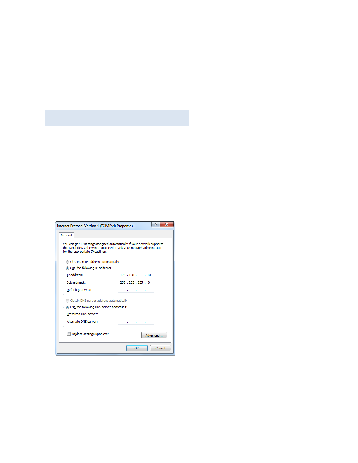
Step 4: Find and double click Internet Protocol Version 4(TCP/IPv4).
Step 5: Select Use the following IP address, type in the IP address: 192.168.2.x (2~253), Subnet mask:
255.255.255.0 and click OK.
Step 6: Click OK on the Local Area Connection Properties window (see Step 4 for the screenshot).
Page 54

Appendix
- 49 -
Safety and emission statement
CE Mark Warning
This is a Class B product. In a domestic environment, this product may cause radio interference, in which case the
user may be required to take adequate measures.
NOTE: (1) The manufacturer is not responsible for any radio or TV interference caused by unauthorized
modifications to this equipment. (2) To avoid unnecessary radiation interference, it is recommended to use a
shielded RJ45 cable.
Declaration of Conformity
Hereby, IP-COM NETWORKS Co., LTD. declares that the radio equipment type AP255_US is in compliance with
Directive 2014/53/EU.
The full text of the EU declaration of conformity is available at the following internet address:
http://www.ip-com.com.cn/en/ce.html
Operate Frequency:2412-2472 MHz EIRP Power(Max.):19.8 dBm Software Version:v1.0.0.4
RECYCLING
This product bears the selective sorting symbol for Waste electrical and electronic equipment (WEEE). This means that this
product must be handled pursuant to European directive 2012/19/EU in order to be recycled or dismantled to minimize its
impact on the environment.
User has the choice to give his product to a competent recycling organization or to the retailer when he buys an new
electrical or electronic equipment.
Page 55

Appendix
- 50 -
FCC Statement
This device complies with Part 15 of the FCC Rules. Operation is subject to the following two conditions:
(1) This device may not cause harmful interference, and (2) this device must accept any interference
received, including interference that may cause undesired operation.
This equipment has been tested and found to comply with the limits for a Class B digital device, pursuant
to Part 15 of the FCC Rules. These limits are designed to provide reasonable protection against harmful
interference in a residential installation. This equipment generates, uses and can radiate radio frequency
energy and, if not installed and used in accordance with the instructions, may cause harmful interference
to radio communications. However, there is no guarantee that interference will not occur in a particular
installation. If this equipment does cause harmful interference to radio or television reception, which can
be determined by turning the equipment off and on, the user is encouraged to try to correct the
interference by one of the following measures:
— Reorient or relocate the receiving antenna.
— Increase the separation between the equipment and receiver.
— Connect the equipment into an outlet on a circuit different from that to which the receiver is connected.
— Consult the dealer or an experienced radio/TV technician for help.
FCC Caution: Any changes or modifications not expressly approved by the party responsible for
compliance could void the user's authority to operate this equipment.
This transmitter must not be co-located or operating in conjunction with any other antenna or transmitter.
The manufacturer is not responsible for any radio or TV interference caused by unauthorized
modifications to this equipment.
Radiation Exposure Statement
This equipment complies with FCC radiation exposure limits set forth for an uncontrolled environment. This
equipment should be installed and operated with minimum distance 20cm between the radiator & your body.
NOTE: (1) The manufacturer is not responsible for any radio or TV interference caused by unauthorized
modifications to this equipment. (2) To avoid unnecessary radiation interference, it is recommended to use a
shielded RJ45 cable.
 Loading...