

Page 1

User Guide
AC3000 Tri-band Cable-Free WiFi Router
Page 2

i
Copyright Statement
© 2021 IP-COM Networks Co., Ltd. All rights reserved.
is the registered trademark of IP-COM Networks Co., Ltd. Other brand
and product names mentioned herein are trademarks or registered trademarks of their
respective holders. Copyright of the whole product as integration, including its accessories
and software, belongs to IP-COM Networks Co., Ltd. No part of this publication can be
reproduced, transmitted, transcribed, stored in a retrieval system, or translated into any
language in any form or by any means without the prior written permission of IP-COM
Networks Co., Ltd.
Disclaimer
Pictures, images and product specifications herein are for references only. To improve internal
design, operational function, and/or reliability, IP-COM reserves the right to make changes to
the products described in this document without obligation to notify any person or
organization of such revisions or changes. IP-COM does not assume any liability that may
occur due to the use or application of the product or circuit layout(s) described herein. Every
effort has been made in the preparation of this document to ensure accuracy of the contents,
but all statements, information and recommendations in this document do not constitute the
warranty of any kind, express or implied.
Page 3
ii
Preface
Thank you for choosing IP-COM. Please read this user guide before you start with CompFi 6
AC3000 Tri-band Cable-Free WiFi Router.
Conventions
The typographical elements that may be found in this document are defined as follows.
Item
Presentation
Example
Cascading menus
>
System > Live Users
Parameter and value
Bold
Set User Name to Tom.
Variable
Italic
Format: XX:XX:XX:XX:XX:XX
UI control
Bold
On the Policy page, click the OK button.
Message
“”
The “Success” message appears.
The symbols that may be found in this document are defined as follows.
Symbol
Meaning
This format is used to highlight information of importance or special interest.
Ignoring this type of note may result in ineffective configurations, loss of data or
damage to the device.
This format is used to highlight a procedure that will save time or resources.
For more documents
Go to our website at www.ip-com.com.cn and search for the latest documents for this
product.
Document
Description
Data sheet
It introduces the basic information of the device, including product overview,
selling points and specifications.
Quick installation
guide
It introduces how to set up the device quickly for internet access, the descriptions
of LED indicators, ports, and buttons, FAQ, statement information, and so on.
User guide
It introduces how to set up more functions of the device for more requirements,
including all functions on the web UI of the device.
Page 4
i
Technical Support
If you need more help, contact us by any of the following means. We will be glad to assist you
as soon as possible.
+86-755-27653089
www.ip-com.com.cn
Revision History
IP-COM is constantly searching for ways to improve its products and documentation. The
following table indicates any changes that might have been made since the user guide was
released.
Version
Date
Description
V1.0
2021-12-27
Original publication
Page 5

ii
Contents
1 Login ........................................................................................................................................................................ 1
1.1 Log in to the web UI .................................................................................................................................................. 1
1.1.1 Log in to the Cable-Free (Router Mode) device................................................................................................. 1
1.1.2 Log in to the Cable-Free (AP Mode) device ....................................................................................................... 4
1.2 Log out of the web UI ............................................................................................................................................... 7
2 Web UI ..................................................................................................................................................................... 8
2.1 Web UI layout ........................................................................................................................................................... 8
2.2 Frequently-used elements ........................................................................................................................................ 9
3 Cable-Free (Router Mode) ...................................................................................................................................... 10
3.1 System status .......................................................................................................................................................... 11
3.1.1 Check physical connections and device info .................................................................................................... 11
3.1.2 Add secondary nodes ...................................................................................................................................... 17
3.1.3 Monitor traffic ................................................................................................................................................. 18
3.1.4 Manage online devices .................................................................................................................................... 20
3.2 Internet settings ..................................................................................................................................................... 23
3.2.1 Internet settings .............................................................................................................................................. 23
3.2.2 WAN parameters ............................................................................................................................................. 32
3.2.3 LAN settings ..................................................................................................................................................... 36
3.2.4 VLAN settings ................................................................................................................................................... 39
3.3 Wireless .................................................................................................................................................................. 44
3.3.1 Wireless settings .............................................................................................................................................. 44
3.3.2 Max rate & isolation ........................................................................................................................................ 45
3.3.3 MAC filters ....................................................................................................................................................... 47
3.3.4 Advanced ......................................................................................................................................................... 52
3.3.5 Guest network ................................................................................................................................................. 56
3.4 Node management ................................................................................................................................................. 59
3.4.1 Overview.......................................................................................................................................................... 59
3.4.2 Wireless policy ................................................................................................................................................. 60
3.4.3 Maintenance.................................................................................................................................................... 72
3.4.4 Topology routing .............................................................................................................................................. 81
3.5 Smart optimization ................................................................................................................................................. 87
3.6 Address reservation ................................................................................................................................................ 88
3.6.1 Overview.......................................................................................................................................................... 88
3.6.2 Configure address reservation ......................................................................................................................... 89
3.7 Bandwidth control .................................................................................................................................................. 91
Page 6

iii
3.7.1 Overview.......................................................................................................................................................... 91
3.7.2 Manual............................................................................................................................................................. 92
3.7.3 Auto ................................................................................................................................................................. 94
3.7.4 Limit by group .................................................................................................................................................. 95
3.7.5 Example of configuring limit by group rules .................................................................................................... 97
3.8 Authentication ...................................................................................................................................................... 101
3.8.1 Captive portal ................................................................................................................................................ 101
3.8.2 User management ......................................................................................................................................... 108
3.8.3 Example of configuring user management .................................................................................................... 112
3.9 Filter management ............................................................................................................................................... 130
3.9.1 IP group/time group ...................................................................................................................................... 130
3.9.2 MAC address filter ......................................................................................................................................... 132
3.9.3 IP address filter .............................................................................................................................................. 138
3.9.4 Port filter ....................................................................................................................................................... 143
3.9.5 URL filter ........................................................................................................................................................ 149
3.10 More ................................................................................................................................................................... 159
3.10.1 Static routing ............................................................................................................................................... 159
3.10.2 Port mirroring .............................................................................................................................................. 162
3.10.3 Remote WEB management ......................................................................................................................... 163
3.10.4 DDNS ........................................................................................................................................................... 166
3.10.5 Port forwarding ........................................................................................................................................... 172
3.10.6 DMZ host ..................................................................................................................................................... 178
3.10.7 UPnP ............................................................................................................................................................ 182
3.10.8 Security settings .......................................................................................................................................... 183
3.10.9 VPN server ................................................................................................................................................... 185
3.10.10 VPN client .................................................................................................................................................. 195
3.10.11 IPSec .......................................................................................................................................................... 196
3.10.12 Multi-WAN policy ...................................................................................................................................... 209
3.10.13 USB sharing................................................................................................................................................ 213
3.11 Maintenance ....................................................................................................................................................... 220
3.11.1 Reboot ......................................................................................................................................................... 220
3.11.2 Upgrade ....................................................................................................................................................... 220
3.11.3 Reset ............................................................................................................................................................ 223
3.11.4 Password manager ...................................................................................................................................... 224
3.11.5 Custom reboot ............................................................................................................................................. 225
3.11.6 Backup/restore ............................................................................................................................................ 226
3.11.7 System log.................................................................................................................................................... 227
3.11.8 Diagnostic tool ............................................................................................................................................. 228
3.11.9 System time ................................................................................................................................................. 230
3.11.10 Function center ......................................................................................................................................... 232
4 Cable-Free (AP Mode) ........................................................................................................................................... 233
Page 7

iv
4.1 System status ........................................................................................................................................................ 234
4.1.1 Add secondary node devices ......................................................................................................................... 234
4.1.2 Check device info ........................................................................................................................................... 235
4.1.3 Manage online devices .................................................................................................................................. 239
4.1.4 Check the RF status ....................................................................................................................................... 240
4.2 Wireless ................................................................................................................................................................ 241
4.2.1 Wireless settings ............................................................................................................................................ 241
4.2.2 Max rate & isolation ...................................................................................................................................... 242
4.2.3 MAC filters ..................................................................................................................................................... 243
4.2.4 Advanced ....................................................................................................................................................... 248
4.2.5 Spectrum analysis .......................................................................................................................................... 251
4.3 Smart optimization ............................................................................................................................................... 253
4.4 More ..................................................................................................................................................................... 254
4.4.1 LAN settings ................................................................................................................................................... 254
4.4.2 Remote WEB management ........................................................................................................................... 256
4.4.3 QVLAN ........................................................................................................................................................... 258
4.5 Maintenance ......................................................................................................................................................... 263
4.5.1 Reboot ........................................................................................................................................................... 263
4.5.2 Upgrade ......................................................................................................................................................... 263
4.5.3 Reset .............................................................................................................................................................. 266
4.5.4 Password manager ........................................................................................................................................ 267
4.5.5 Custom reboot ............................................................................................................................................... 267
4.5.6 Backup/restore .............................................................................................................................................. 269
4.5.7 System log...................................................................................................................................................... 270
4.5.8 Diagnostic tool ............................................................................................................................................... 271
4.5.9 System time ................................................................................................................................................... 273
Appendix ................................................................................................................................................................. 276
Page 8
Version 1.0
1
1 Login
1.1 Log in to the web UI
For initial use of this device, you can refer to quick installation guide to complete the setup
wizard before entering the web UI.
If the device has been configured, please refer to the following steps.
1.1.1 Log in to the Cable-Free (Router Mode) device
Tip
− In Cable-Free (Router Mode), the PoE WAN/LAN1 and WAN/LAN2 ports of the device serve as WAN
ports.
− The device works in Cable-Free (Router Mode) by default.
◼
Log in with your computer
1. Connect the computer to the WAN/LAN3 or LAN4 port of the device with an Ethernet cable.
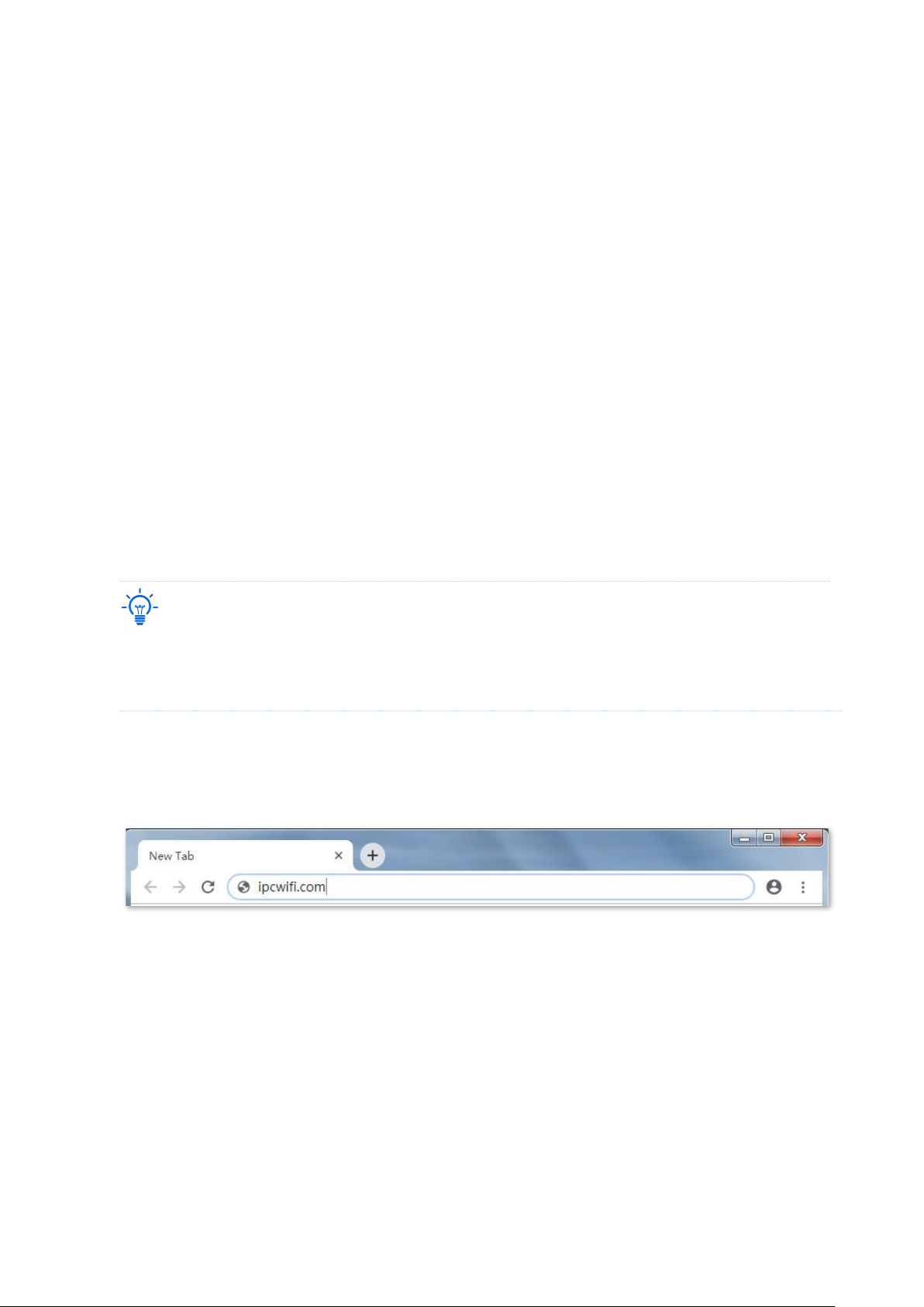
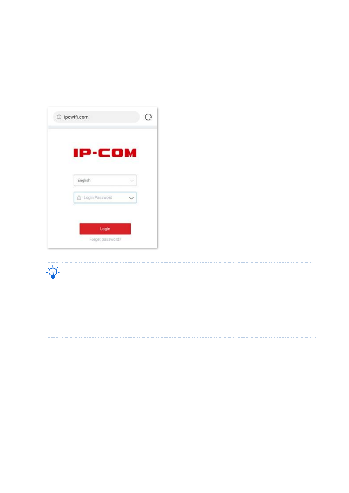
2. Start a browser on the computer, such as Google Chrome, and visit www.ipcwifi.com
3. Enter the login password, and click Login.
Page 9
Version 1.0
2
----End
Tip
If the above page does not appear, please try the following solutions:
− Ensure that the device is powered on.
− Ensure that your computer is connected to the LAN port of the device, and is set to Obtain an IP
address automatically and Obtain DNS server address automatically.
− Reset the device and log in again. How to reset: When the SYS LED indicator is blinking, hold down the
RESET button with a needle-like object for about 8 seconds and release it when all the LED indicators
light solid green. When the SYS LED indicator blinks again, the device is reset successfully.
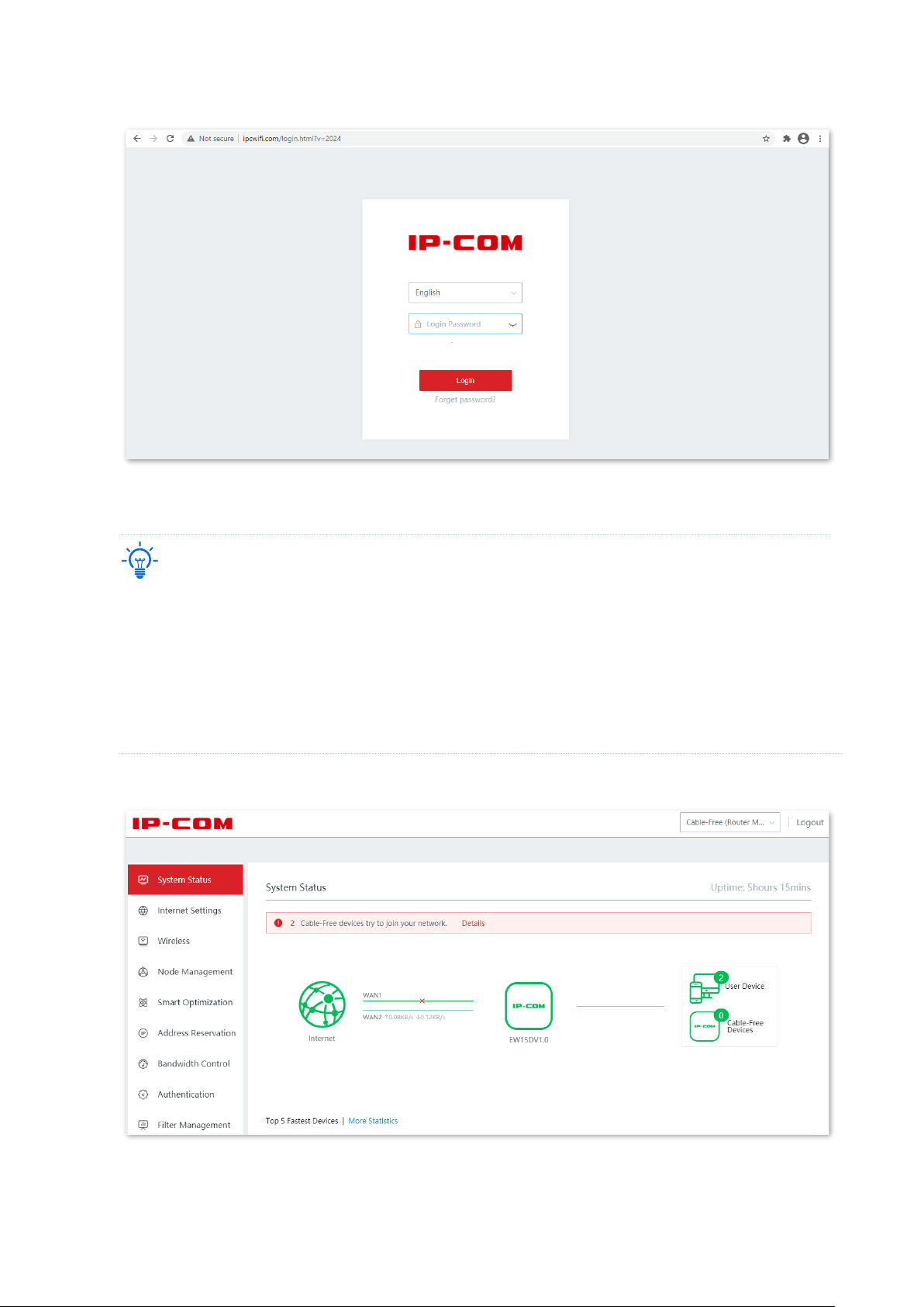
Log in to the web UI successfully. See the following figure.
Page 10
Version 1.0
3
◼
Log in with your smartphone/iPad
Take smartphone as an example.
1. Connect your smartphone to the WiFi network of the device.
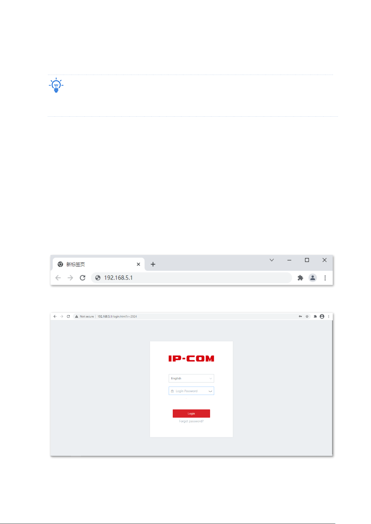
2. Start a browser on the smartphone, and visit www.ipcwifi.com
3. Enter the login password, and click Login.
Tip
If the above page does not appear, please try the following solutions:
− Ensure that your smartphone is connected to the WiFi network of the device.
− Ensure that the mobile data is disabled.
− Reset the device and log in again. How to reset: When the SYS LED indicator is blinking, hold down the
RESET button with a needle-like object for about 8 seconds and release it when all the LED indicators
light solid green. When the SYS LED indicator blinks again, the device is reset successfully.
----End
Page 11
Version 1.0
4
1.1.2 Log in to the Cable-Free (AP Mode) device
Tip
In Cable-Free (AP Mode), the PoE WAN/LAN1 port of the device serves as a LAN port generally connecting
to an upstream router, and the WAN/LAN2 port serves as a LAN port connecting to a LAN device.
◼
Log in with your computer
1. Connect the computer to the WAN/LAN2, WAN/LAN3, or LAN4 port of the device with an
Ethernet cable.
2. Set the IP address of the computer to make sure the computer and the device are on the
same segment. By default, the IP address of the device is 192.168.5.1. If the device connects
to an upstream router or AC, its IP address can be obtained from the connected upstream
router or AC.
For example, if the IP address of the device is 192.168.5.1, set the IP address of the computer
to 192.168.5.X (X ranges from 2 to 254 and is not occupied by other devices), and the subnet
mask to 255.255.255.0.
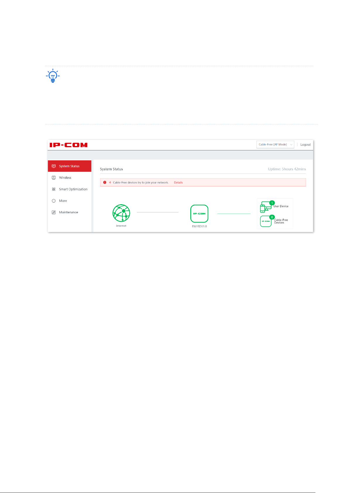
3. Start a browser on your computer, such as Google, and enter the management IP address of
the device, which is 192.168.5.1 in this example.
4. Enter the login password and click Login.
Page 12
Version 1.0
5
----End
Tip
If the above page does not appear, please try the following solutions:
− Ensure the device is powered on.
− Ensure that the computer is connected to the LAN port of the device, and the computer and the device
are on the same network segment.
Log in to the web UI successfully. See the following figure.
◼
Log in with your smartphone/iPad
Take smartphone as an example.
1. Connect your smartphone to the WiFi network of the device.
2. Configure the IP address of the smartphone to make sure the smartphone and the device are
on the same network segment.
For example, if the IP address of the device is 192.168.5.1, configure the IP address of the
smartphone to 192.168.5.X (X ranges from 2 to 254 and is not occupied by other devices), and
the subnet mask to 255.255.255.0.
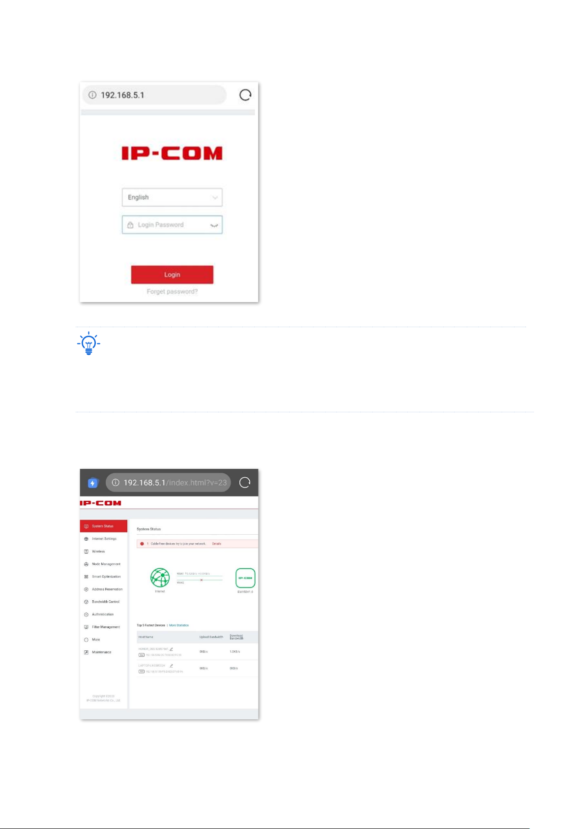
3. Start a browser on the smartphone, and visit 192.168.5.1
4. Enter the login password, and click Login.
Page 13
Version 1.0
6
Tip
If the above page does not appear, please try the following solutions:
− Ensure your phone has connected to the WiFi network of the device.
− Ensure that the mobile data is disabled.
----End
Log in to the web UI successfully. See the following figure.
Page 14

Version 1.0
7
1.2 Log out of the web UI
If you log in to the web UI of the device and perform no operation within 20 minutes, the
device logs you out automatically.
You can log out by clicking Logout on the upper right corner of the web UI as well.
Page 15
Version 1.0
8
2 Web UI
2.1 Web UI layout
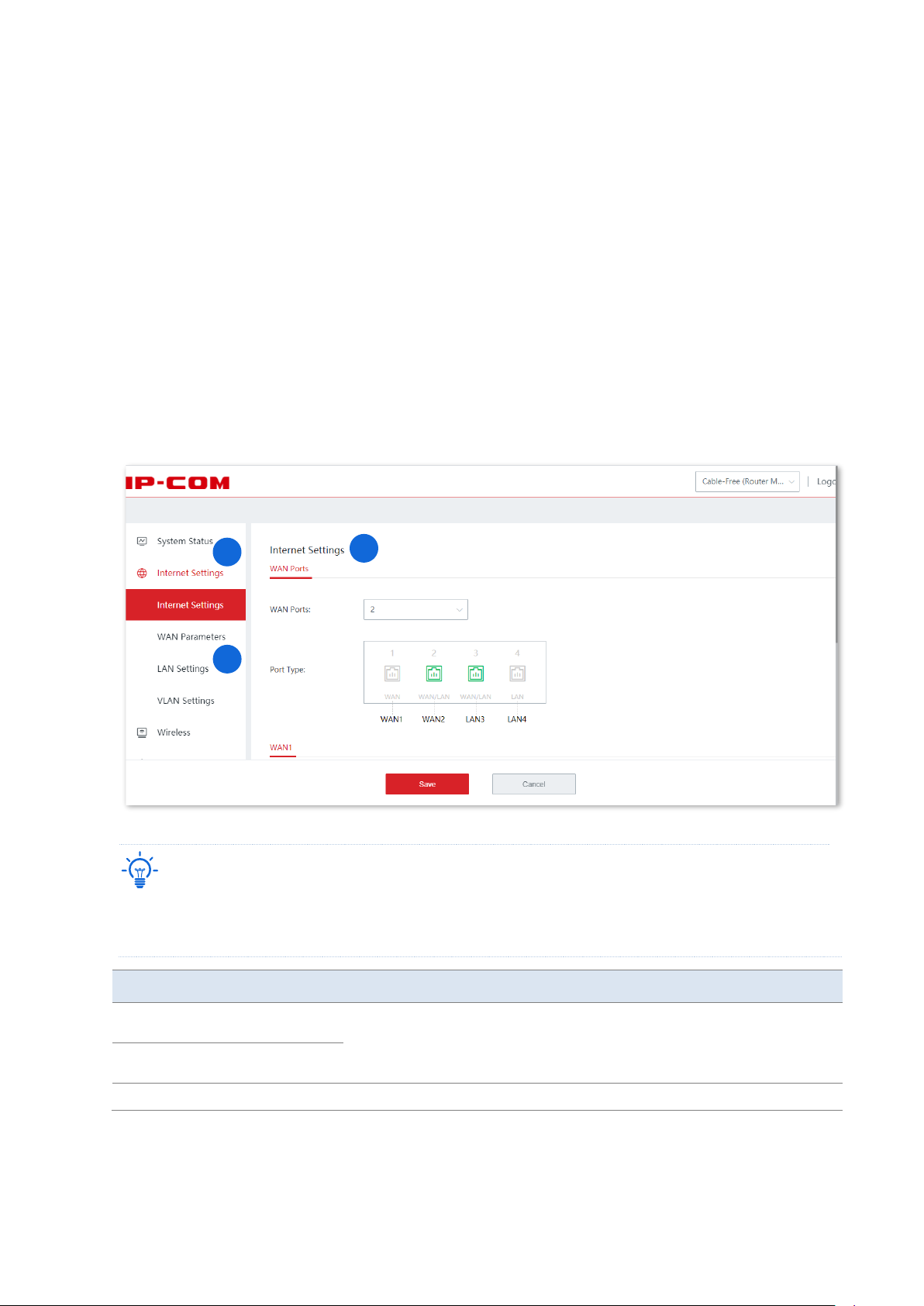
The web UI of the device consists of three sections, including the level-1, and level-2
navigation bar, and the configuration area. See the following figure.
Tip
Features and parameters in gray indicate that they are not available or cannot be changed under the current
condition.
NO.
Name
Description
❶
Level-1 navigation
bar
It is used to display the function menu of the device. Users can select
functions in the navigation bars and the configuration appears in the
configuration area.
❷
Level-2 navigation
bar
❸
Configuration area
It is used to view or modify your configuration.
1 2 3
Page 16
Version 1.0
9
2.2 Frequently-used elements
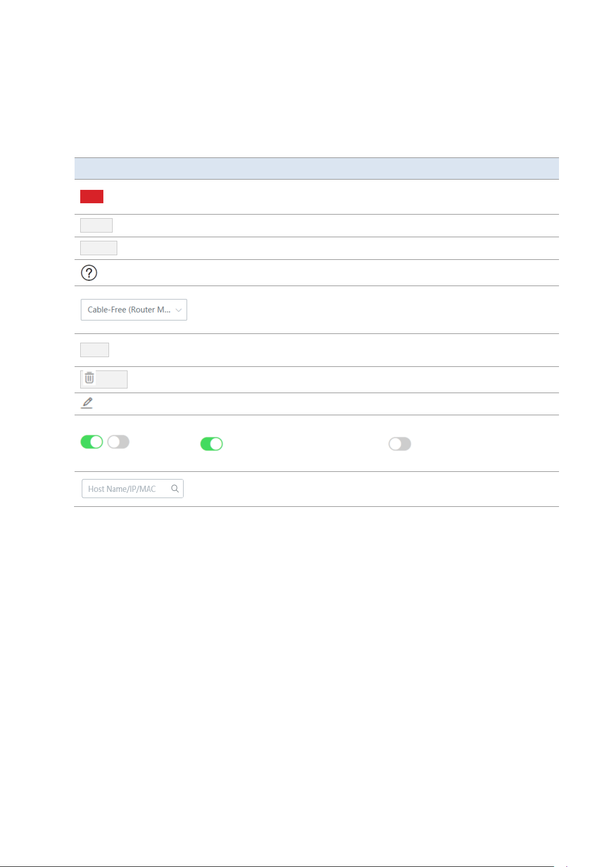
The following table describes the frequently-used buttons available on the web UI of the
device.
Button
Description
Save
It is used to save the configuration on the current page and enable the
configuration to take effect.
Cancel
It is used to cancel the changes you made.
Refresh
It is used to refresh the current page to check the latest configuration.
It is used to view help information for the current page.
Click the drop-down list to select and switch the work mode of the cable-free
device. You can switch between Cable-Free (Router Mode) and Cable-Free (AP
Mode).
+ Add
It is used to create a new rule or policy.
Delete
It is used to delete the selected rule, policy, or information.
It is used to edit the corresponding rule, policy or information.
,
It displays the status of the function, including enabled and disabled.
specifies the function is enabled and specifies the function is
disabled.
It is used to search for relevant content on the page. The keywords supported in
the search bar are shown in the search bar preset content.
Page 17
Version 1.0
10
3 Cable-Free (Router Mode)
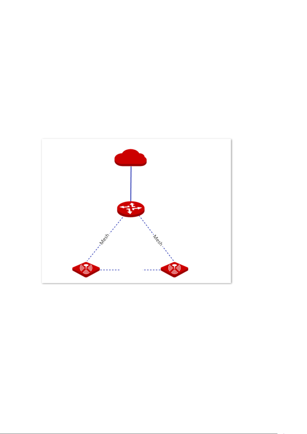
In this mode, the device serves as a router which provides internet access and can form a
separate cable-free network with other cable-free devices.
Internet
Cable-Free primary node:
Cable-Free (Router Mode)
Cable-Free secondary node
Cable-Free secondary node
Mesh
Page 18
Version 1.0
11
3.1 System status
In this section, you can:
◼
Check physical connections and device info
◼
Add secondary nodes
◼
Monitor traffic
◼
Manage online devices
3.1.1 Check physical connections and device info
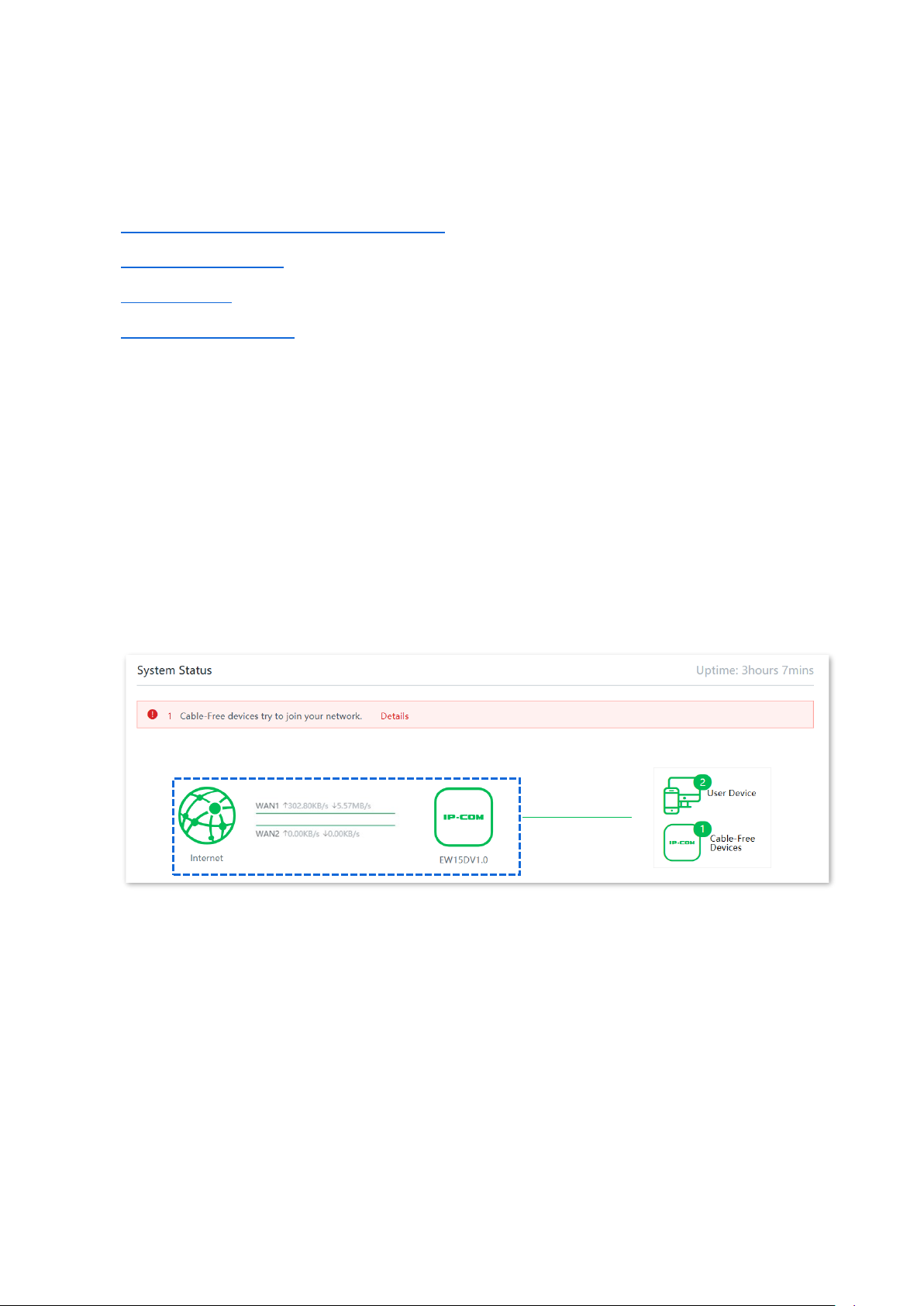
You can check whether the physical connections of the Cable-Free (Router Mode) node are
proper and check the basic information of each node in the cable-free network.
Click System Status to enter the page.
Check physical connections
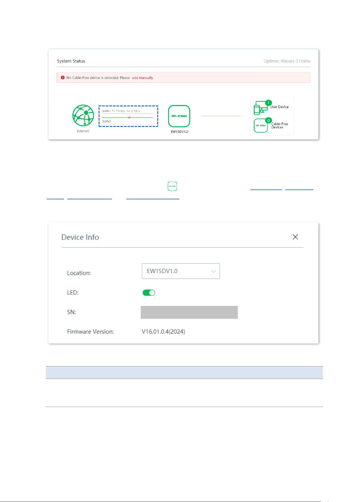
The following figure indicates that the Cable-Free (Router Mode) node is connected to the
internet properly through a WAN port.
The following figure indicates that the Cable-Free (Router Mode) node is not connected to
the internet properly through a WAN port. Please check whether that WAN port of the device
is connected to the internet properly, or the internet connection parameters you set are
correct.
Page 19
Version 1.0
12
Check the information of the cable-free primary node
On the System Status page, click the icon . You can check the basic device info, operating
status, LAN port status and WAN port settings of the cable-free primary node.
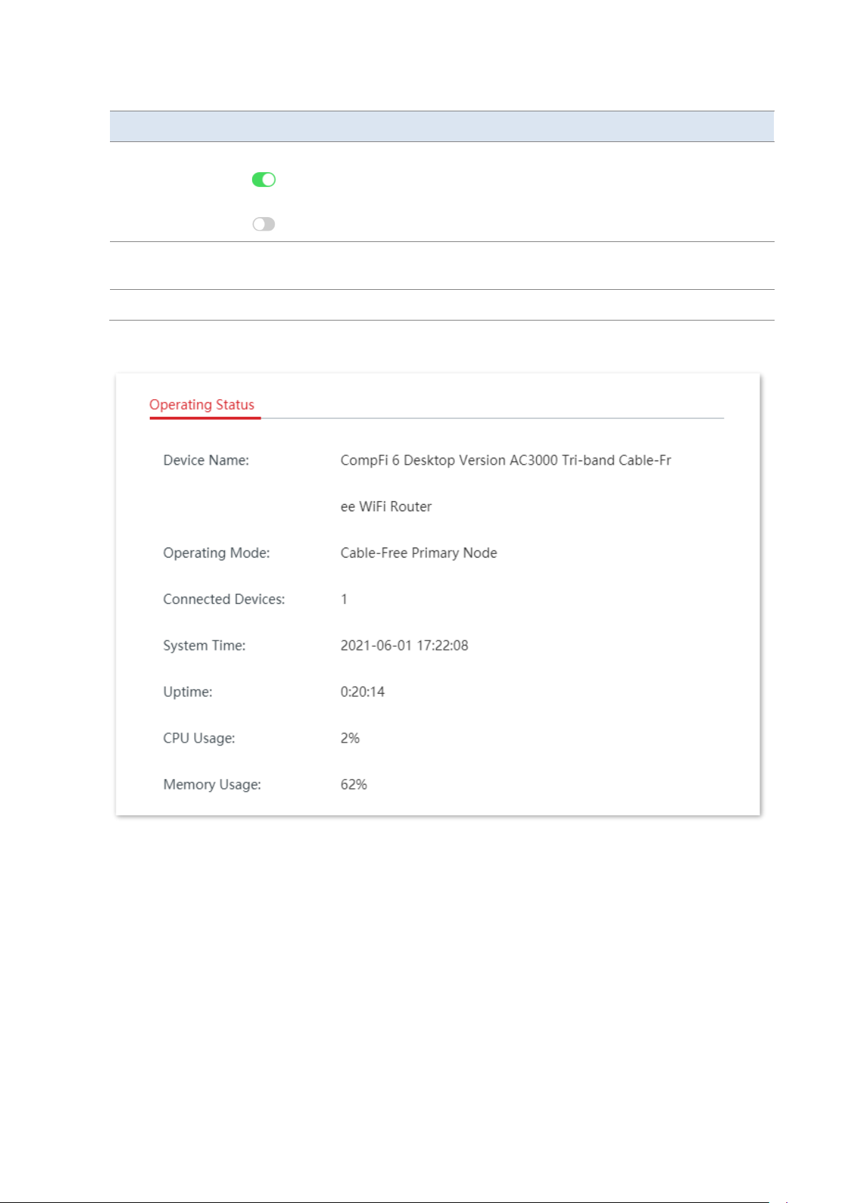
Device info
Parameter description
Parameter
Description
Location
It specifies the location information of the node, which helps you easily locate it.
You can select a location description from the drop-down list or customize one as
required.
Page 20
Version 1.0
13
Parameter
Description
LED
It specifies the status of the LED indicators of the node.
: It indicates that the LED indicators are turned on. You can judge the operating
status of the device based on the LED indicators.
: It indicates that the LED indicators are turned off.
SN
It specifies the serial number of the node, which is used to manually add the node
into a mesh network.
Firmware Version
It specifies the current version of the node.
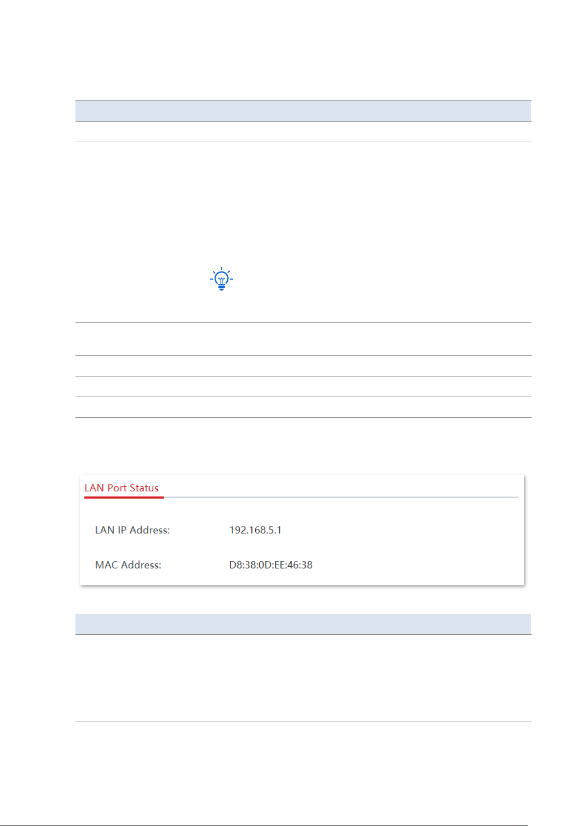
Operating status
Page 21
Version 1.0
14
Parameter description
Parameter
Description
Device Name
It specifies the name of your node.
Operating Mode
It specifies the current operating mode of the node.
−
Cable-Free Primary Node: The node serves as a primary node in the
cable-free network and connects to a wired network. The node is
the only exit to the external network in the cable-free network and
transforms data between the Mesh network and the wired network.
−
Cable-Free Secondary Node: The node serves as a secondary node
in the cable-free network and is used to extend the coverage of the
existing cable-free network through Mesh technology.
Tip
If the node serves as a cable-free secondary node, the PoE WAN/LAN1 port
and the WAN/LAN2 port are LAN ports.
Connected Devices
It specifies the number of devices connected to cable-free network
currently.
System Time
It specifies the current system time of the node.
Uptime
It specifies the duration the node has been running.
CPU Usage
It specifies the current CPU usage of the node.
Memory Usage
It specifies the current memory usage of the node.
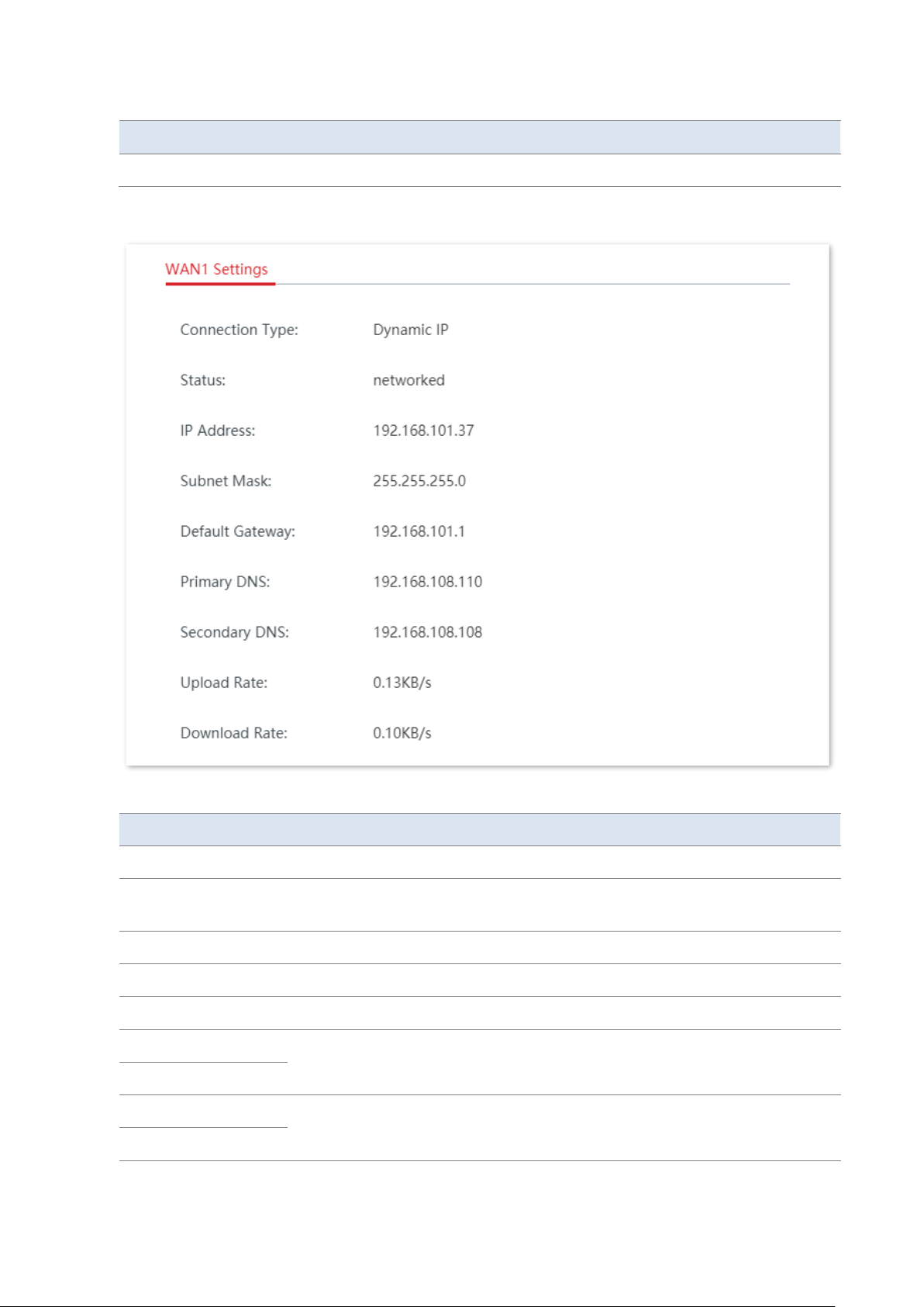
LAN port status
Parameter description
Parameter
Description
LAN IP Address
It specifies the IP address of the LAN port of the node and is also the
management IP address of the node, which is 192.168.5.1 by default. LAN
users can visit this IP address to log in to the management web UI of the
node.
The IP address of the secondary node is automatically obtained from the
DHCP server of the primary node.
Page 22
Version 1.0
15
Parameter
Description
MAC Address
It specifies the physical address of the LAN port of the node.
WAN settings
Parameter description
Parameter
Description
Connection Type
It specifies the internet connection type of the WAN port of the node.
Status
It specifies the connection status of the WAN port of the node. If Disconnected
appears, please check the physical connection of the WAN port.
IP Address
It specifies the IP address of the WAN port of the node.
Subnet Mask
It specifies the subnet mask of the WAN port of the node.
Default Gateway
It specifies the gateway IP address of the WAN port of the node.
Primary DNS
It specifies the primary/secondary DNS server address of the WAN port of the
node.
Secondary DNS
Upload Rate
It specifies the real-time upload/download rate of the WAN port of the node.
Download Rate
Page 23
Version 1.0
16
Check the information of the cable-free secondary nodes
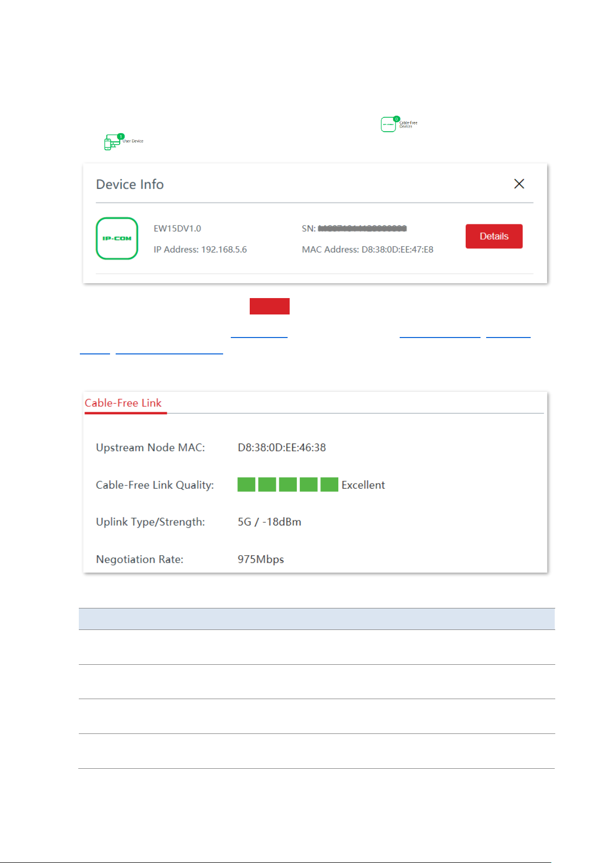
On the System Status page, click the cable-free devices icon next to the user device
icon , you can check the device info of the cable-free secondary nodes.
For more information, please click Details on the page of the target node.
Here, you can check or set the device info of the node, check its operating status, LAN port
status, cable-free link quality, and restart or delete the node.
Cable-free link quality
Parameter description
Parameter
Description
Upstream Node MAC
It specifies the physical address of the interface used by the upstream node in the
Mesh network to form the Mesh link.
Cable-Free Link
Quality
It specifies the connection quality of the cable-free links.
Uplink Type/Strength
It specifies the mode in which the node and its upstream node form a network
and the strength of the signal of the upstream node received by the node.
Negotiation Rate
It specifies the rate at which the node performs negotiation with its upstream
node.
Page 24
Version 1.0
17
Reboot the node
Click Reboot to reboot the node.
Delete the node
Click Delete to delete the node from the cable-free network. Nodes deleted from the cablefree network will be restored to factory settings.
3.1.2 Add secondary nodes
Generally, the primary node device can automatically detect secondary node devices in
factory settings. If your secondary node device fails to be detected, you can also log in to the
web UI of the primary node device to manually add secondary node devices.
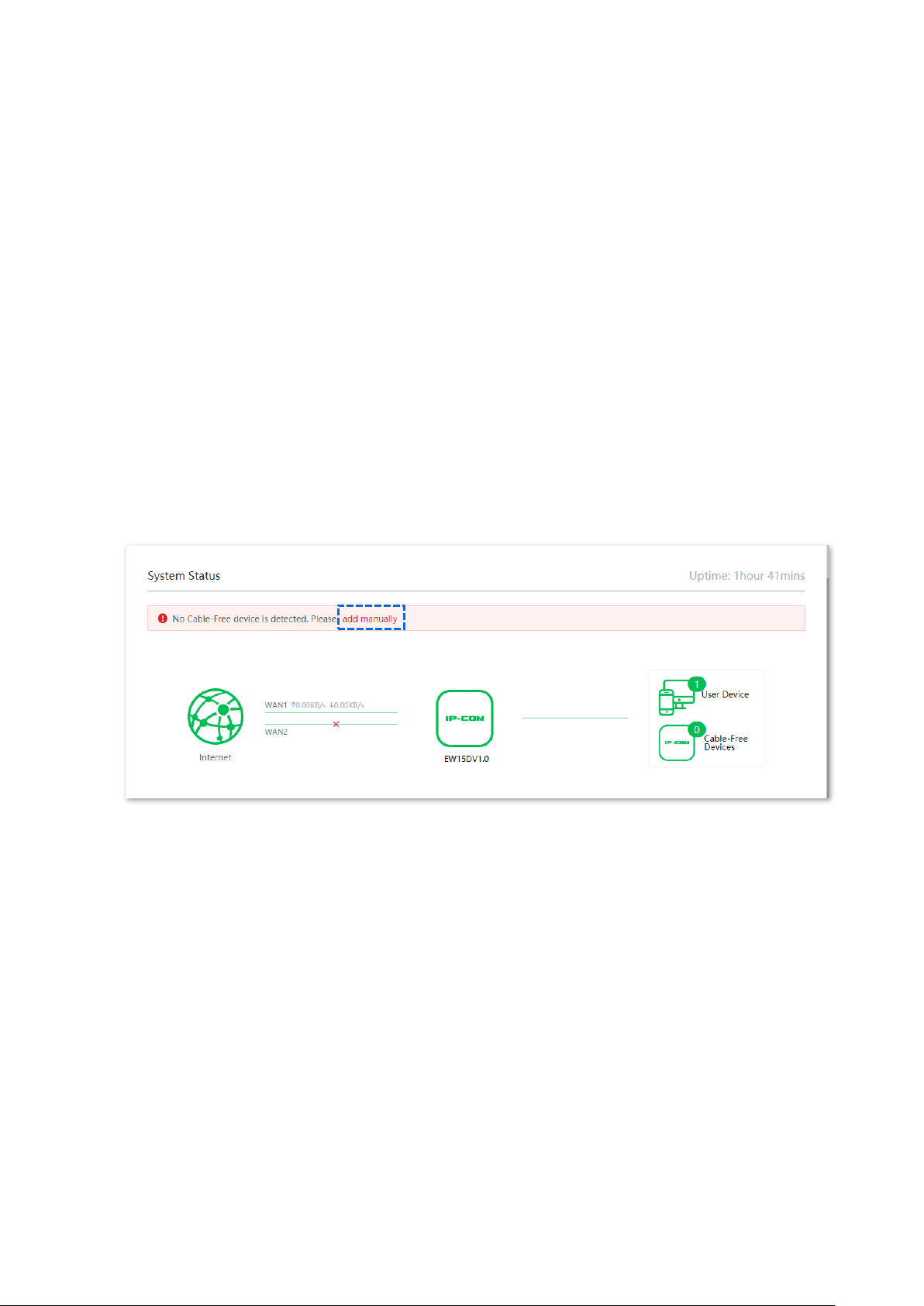
Configuration procedures (add manually)
1. Click System Status to enter the page.
2. Click add manually.
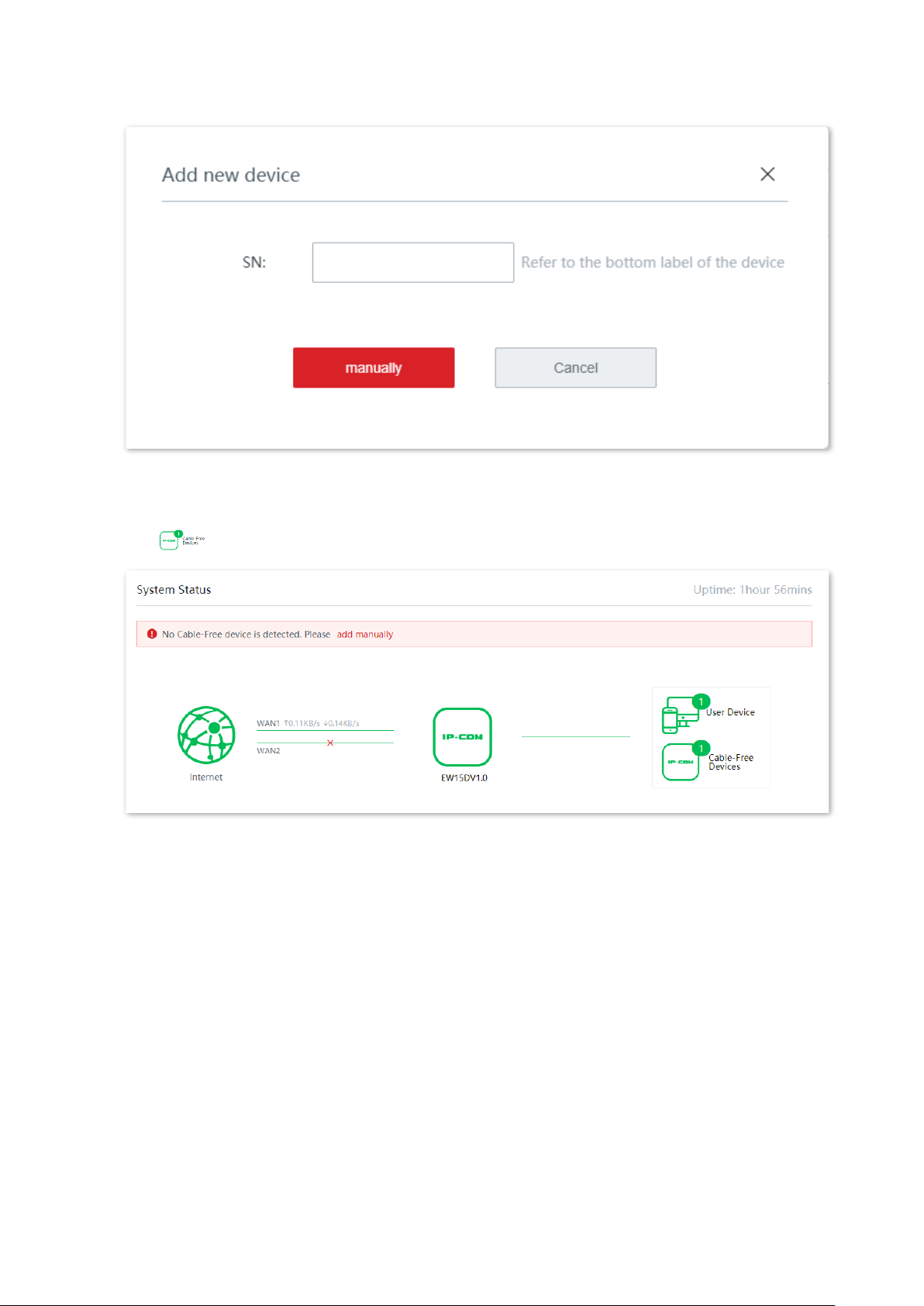
3. Enter the SN (on the surface label) of the Mesh device to be added.
4. Click manually.
Page 25
Version 1.0
18
----End
After the secondary node device is added successfully, you can click the cable-free devices
icon on the right side of the System Status page to check its details.
3.1.3 Monitor traffic
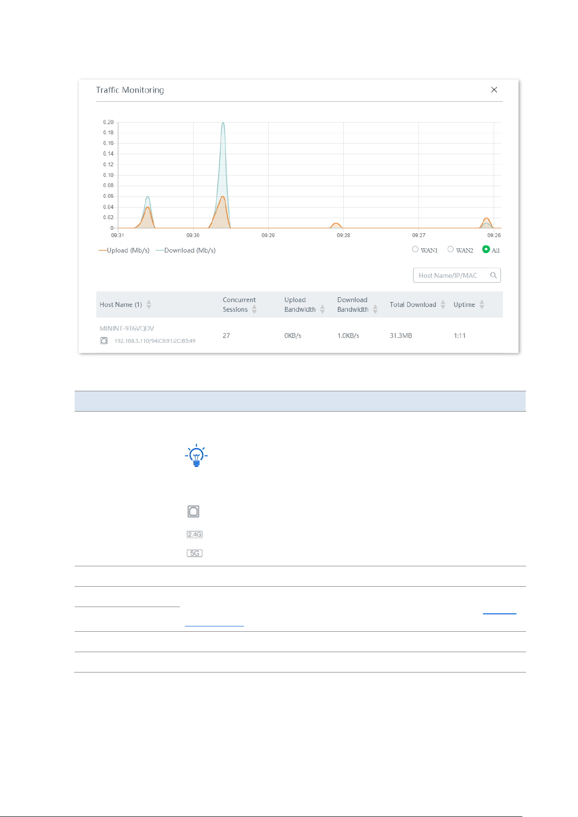
You can view the real-time upload and download bandwidth of the WAN ports, and check the
basic information of a client, such as upload/download bandwidth, uptime and so on.
Click System Status to enter the page, and click More Statistics.
Page 26
Version 1.0
19
Parameter description
Parameter
Description
Host Name
It displays the name, IP address, and MAC address of the connected client.
Tip
If you want to add host name-based rules, such as adding an authentication-free
host using host name, you need to use the host name here.
: The client connects to the device in a wired manner.
: The client connects to the 2.4 GHz WiFi network of the device.
: The client connects to the 5 GHz WiFi network of the device.
Concurrent Sessions
It specifies the concurrent sessions established by the client.
Upload Bandwidth
It displays the current upload/download bandwidth of the client. You can set the
maximum upload/download bandwidth for a client. For details, refer to Manage
online devices.
Download Bandwidth
Total Download
It specifies the total download traffic generated by the client.
Uptime
It specifies the duration the client has been connected.
Page 27
Version 1.0
20
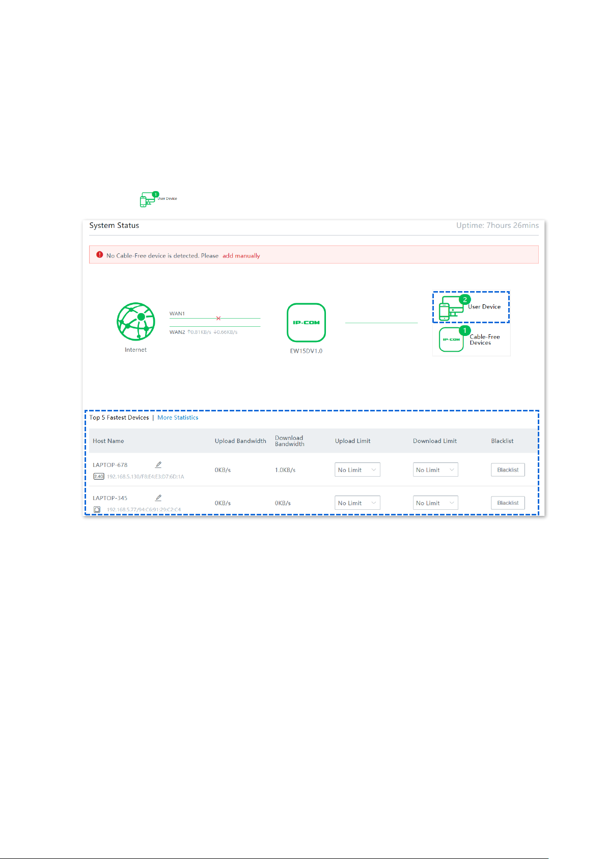
3.1.4 Manage online devices
You can edit the name of user devices, set the upload and download bandwidth separately or
in batches, or block a device from accessing your network.
Click System Status to enter the page.
The System Status page displays the top 5 clients with the highest speed. Click the User
Device icon to manage all connected user devices.
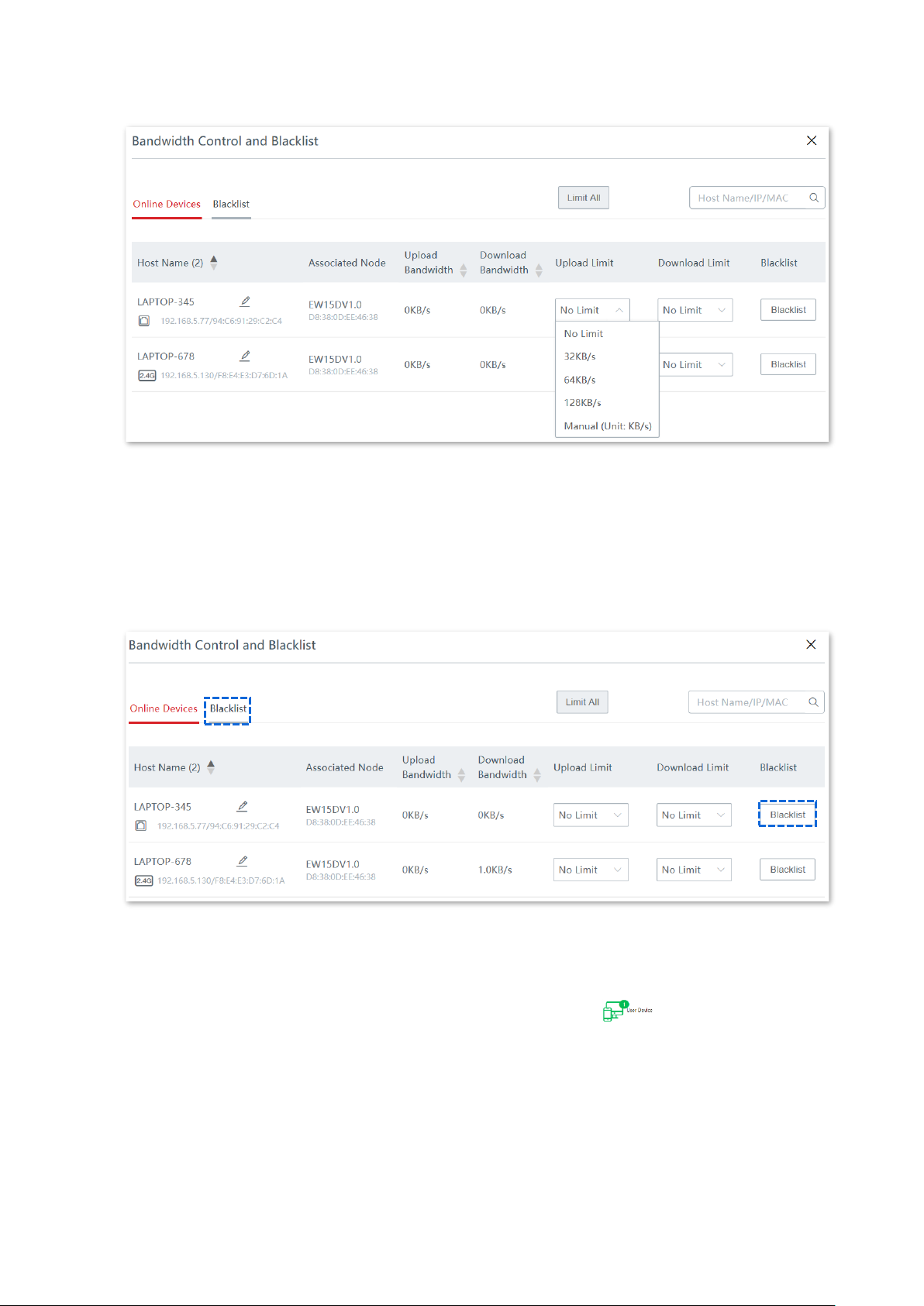
Set bandwidth limit for connected clients
To limit the upload and download bandwidth for one or several devices, select a pre-defined
value from the drop-down list of Upload Limit and Download Limit, or select Manual to
specify a value.
Page 28
Version 1.0
21
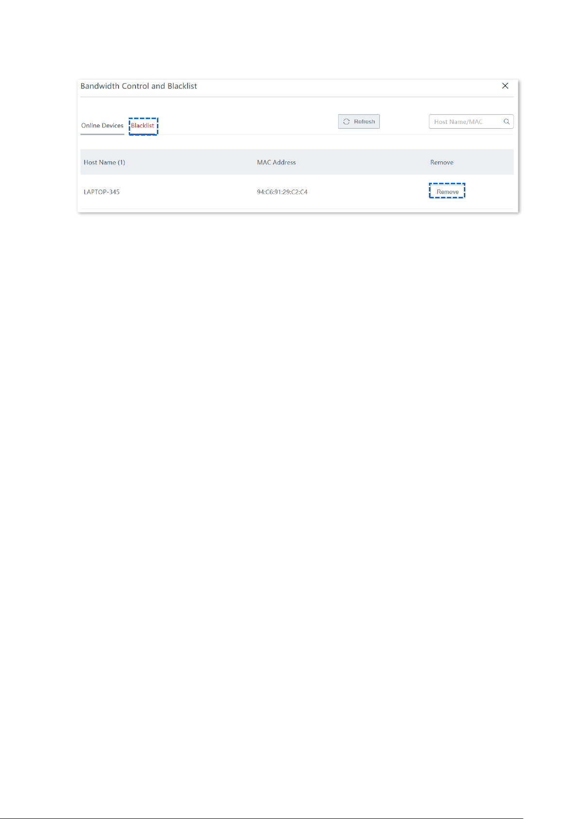
Add devices into the blacklist
To block unknown devices from accessing your network, click the Blacklist button to blacklist
them. The blocked devices will be moved to the Blacklist tab page and cannot access the
internet through the device.
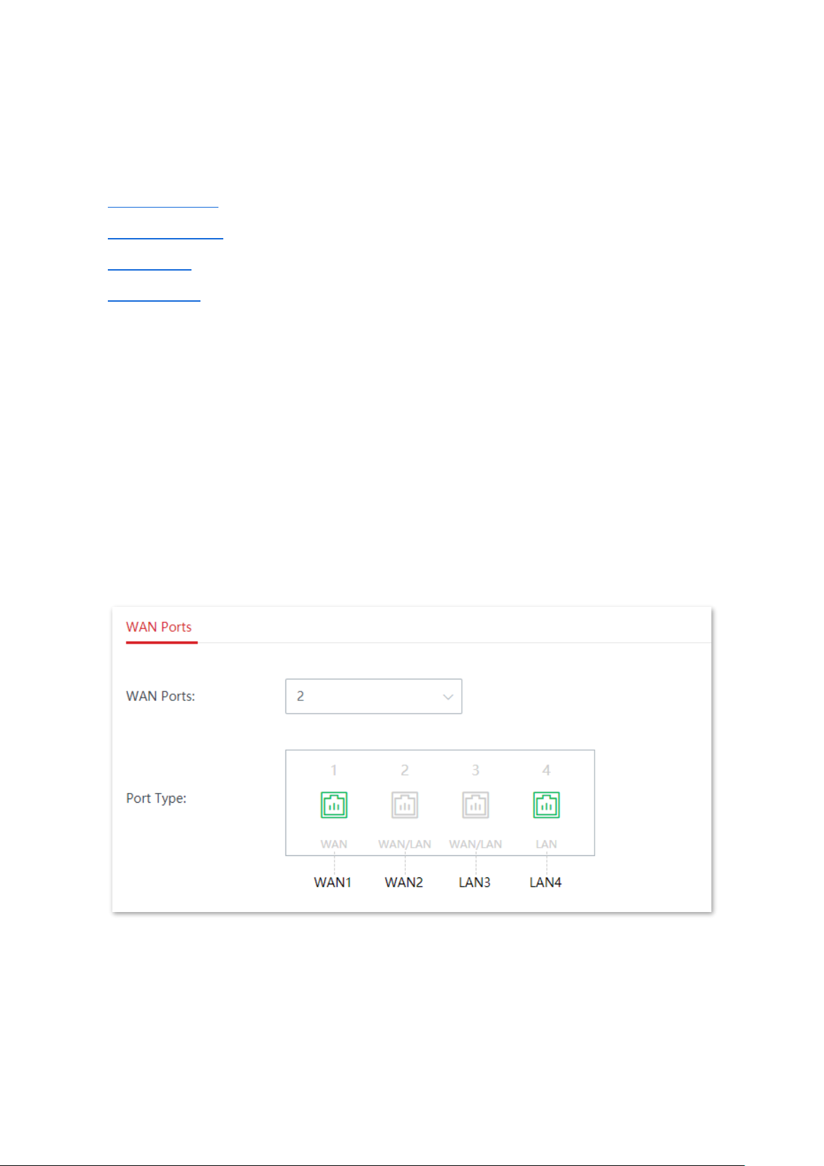
Remove devices from the blacklist
To remove devices from the blacklist, click the User Device icon on the System Status
page, click Blacklist, then click Remove to remove the target device.
Page 29
Version 1.0
22
Page 30
Version 1.0
23
3.2 Internet settings
In this section, you can configure:
◼
Internet settings
◼
WAN parameters
◼
LAN settings
◼
VLAN settings
3.2.1 Internet settings
Overview
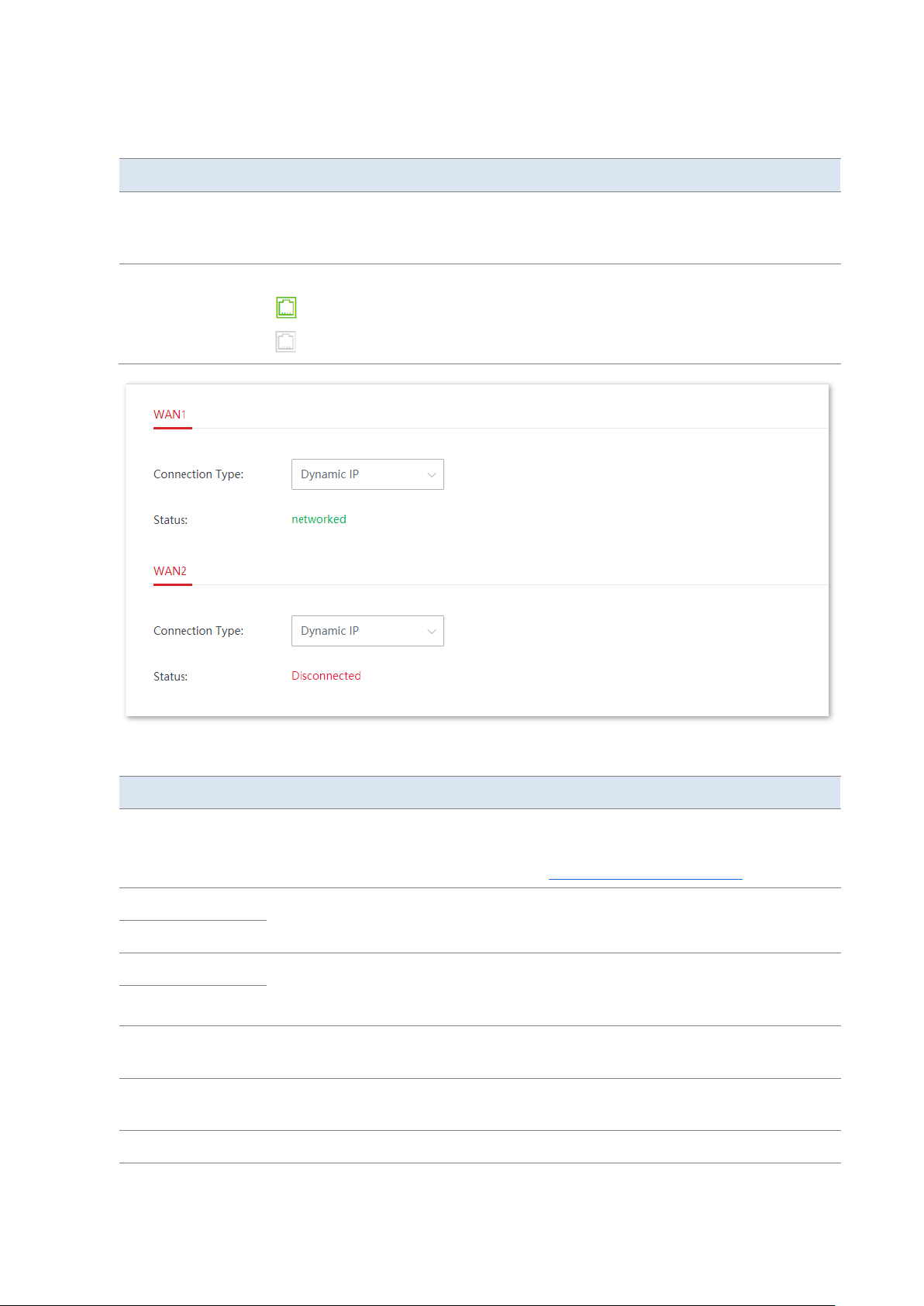
On this page, you can configure or change the internet settings to enable the device to access
the internet.
If you are using the device for the first time or you restored the device to factory settings, you
can follow the quick setup wizard to complete the internet settings. After that, you can
change internet settings or set up more parameters here.
Click Internet Settings to enter the page.
Page 31
Version 1.0
24
Parameter description
Parameter
Description
WAN Ports
It specifies the number of WAN ports. By default, the device has 2 WAN ports (PoE
WAN/LAN1 and WAN/LAN2). You can change the WAN port number as needed.
You can set 3 WAN ports at most.
Port Type
It specifies whether a port is connected.
: The port is connected properly.
: The port is disconnected or not connected properly.
Parameter description
Parameter
Description
Connection Type
It specifies in what way the device connects to the internet.
The options include PPPoE, Static IP, Dynamic IP, PPPoE Russia, PPTP/PPTP Russia,
and L2TP/L2TP Russia. Refer to the table Choose your connection type for details.
PPPoE Username
These two parameters are required only when your internet connection type is
PPPoE or PPPoE Russia. You can obtain them from your ISP.
PPPoE Password
Server Name
These two parameters are required only when your internet connection type is
PPPoE or PPPoE Russia. You can obtain them from your ISP. These two parameters
are optional.
Service Name
PPTP Server
Address
This parameter is required only when your internet connection type is PPTP/PPTP
Russia. You can obtain it from your ISP.
L2TP Server
Address
This parameter is required only when your internet connection type is L2TP/L2TP
Russia. You can obtain it from your ISP.
User Name
These two parameters are required only when your internet connection type is
Page 32
Version 1.0
25
Parameter
Description
Password
PPTP/PPTP Russia or L2TP/L2TP Russia. You can obtain them from your ISP.
Obtain an IP
address
This parameter appears when your internet connection type is PPPoE Russia,
PPTP/PPTP Russia, or L2TP/L2TP Russia. If there is no DHCP server in the network,
select Manual and enter the IP address and related parameters. If there is a DHCP
server in the network, select Auto, and the device will obtain these parameters
from the DHCP server.
IP Address
These parameters are required only when your internet connection type is Static IP
or if you set Obtain an IP address to Manual when your internet connection type is
PPPoE Russia, PPTP/PPTP Russia, or L2TP/L2TP Russia. The Secondary DNS
parameter is optional. You can obtain them from your ISP.
Subnet Mask
Default Gateway
Primary DNS
Secondary DNS
Status
It specifies the internet connection status of the WAN port.
−
Authenticated successfully/networked: The WAN port is connected to the
internet or server.
−
Connecting…: The WAN port of the device is connecting to the internet or
server.
−
Disconnected: The port is physically disconnected, or fails to connect to the
internet or server. Please check whether the physical connection is proper, or
the parameters you entered are correct.
Set up internet connection
Tip
The parameters for accessing the internet are all provided by your ISP.
Choose your connection type
Available parameters
Connection type
PPPoE username, PPPoE password, service name, and server name.
PPPoE
IP address, subnet mask, default gateway, primary DNS, and secondary DNS
(optional)
Static IP
None or the device is connected to an upstream device which can access the
internet and has its DHCP server enabled.
Dynamic IP
Page 33
Version 1.0
26
Available parameters
Connection type
PPPoE username, PPPoE password, service name, and server name.
If the DHCP server of the upstream device is disabled (means you have to select
Manual for Obtain an IP address), then the IP address, subnet mask, default
gateway, and primary DNS are required.
PPPoE Russia
PPTP server address, user name, and password.
If the DHCP server of the upstream device is disabled (means you have to select
Manual for Obtain an IP address), then the IP address, subnet mask, default
gateway, and primary DNS are required.
PPTP/PPTP Russia
L2TP server address, user name, and password.
If the DHCP server of the upstream device is disabled (means you have to select
Manual for Obtain an IP address), then the IP address, subnet mask, default
gateway, and primary DNS are required.
L2TP/L2TP Russia
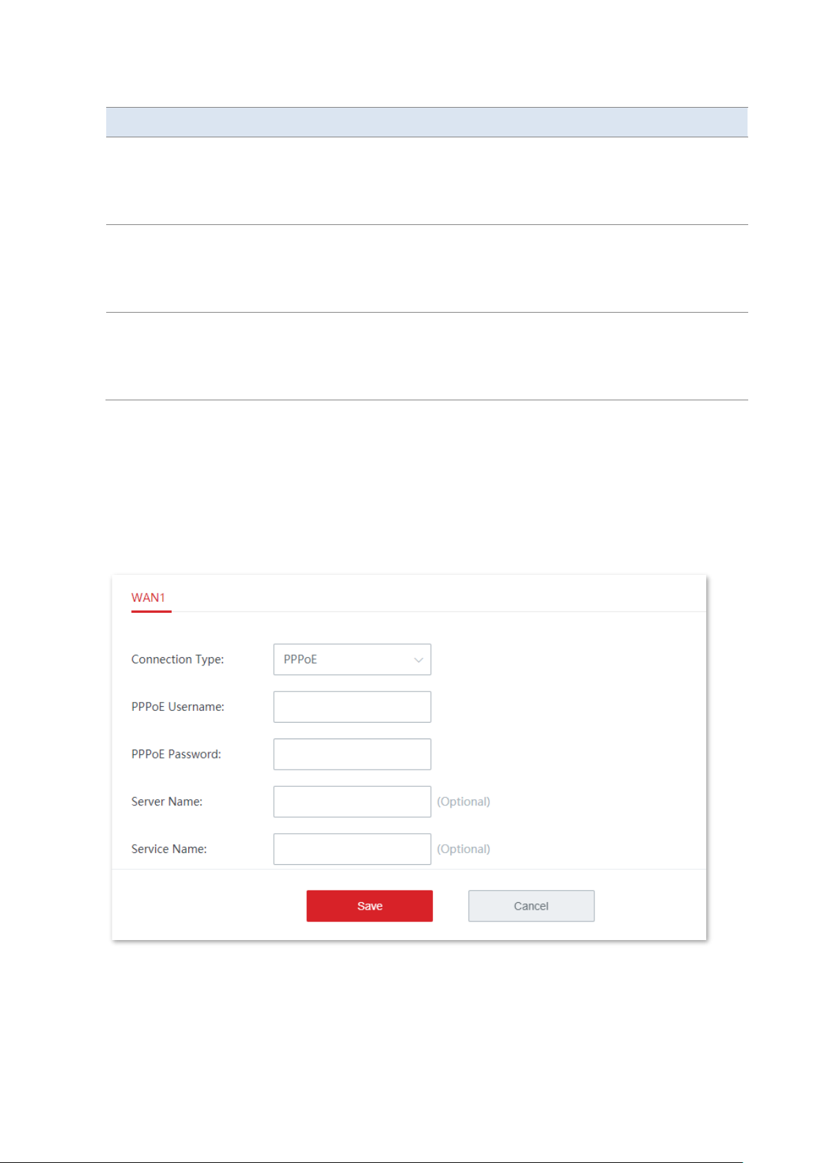
PPPoE
1. Click Internet Settings to enter the page.
2. Set Connection Type to PPPoE.
3. Enter the PPPoE Username and PPPoE Password provided by your ISP. If the Server Name or
Service Name is also provided, enter them in the corresponding input box as well.
4. Click Save.
----End
The device connects to the internet successfully when the Status is displayed as
Authenticated successfully.
Page 34
Version 1.0
27
Tip
If you fail to access the internet, please try the following solutions:
− Check whether the parameters you entered are correct.
− Try changing WAN parameters.
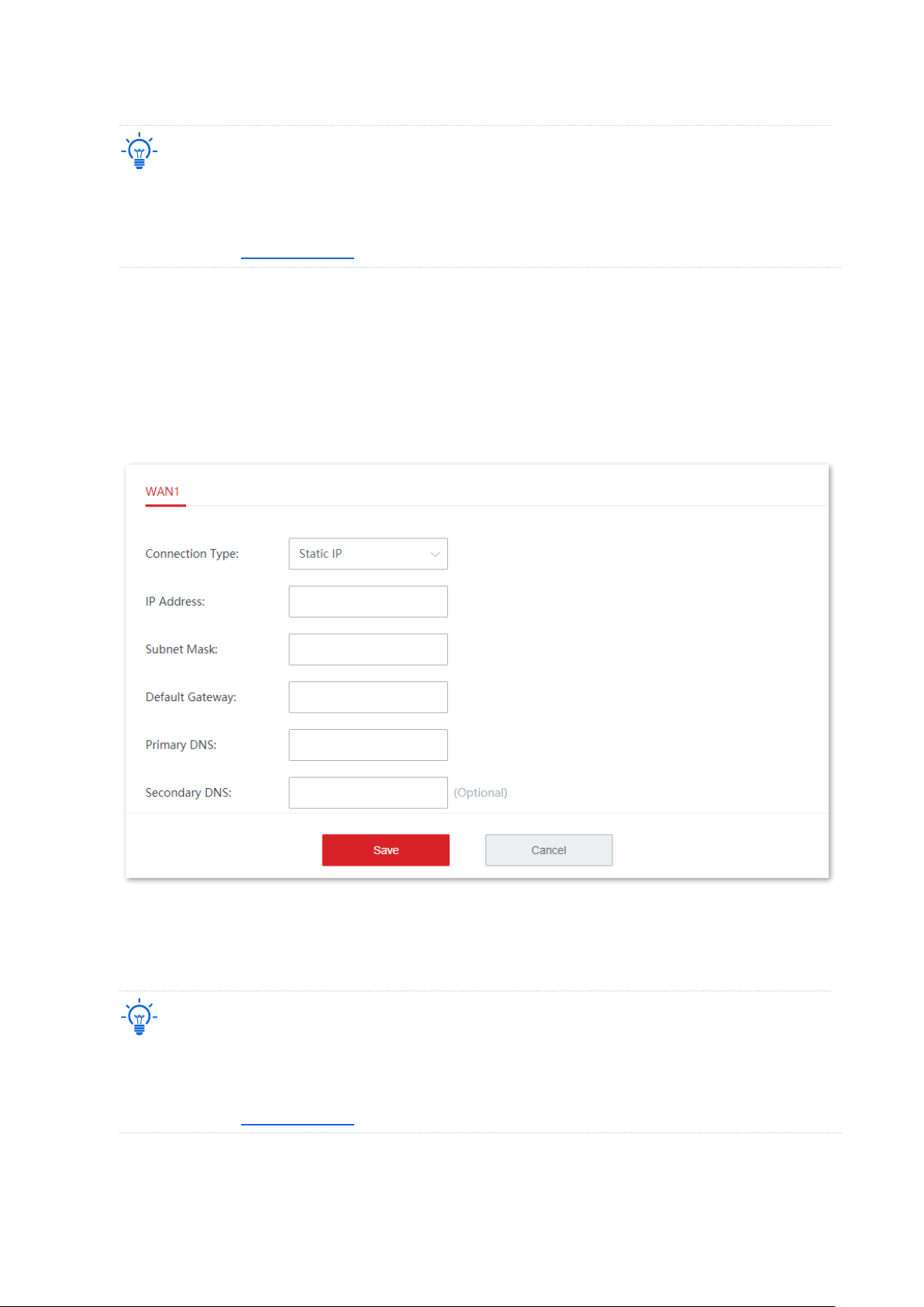
Static IP
1. Click Internet Settings to enter the page.
2. Set Connection Type to Static IP.
3. Enter the IP Address, Subnet Mask, Default Gateway, Primary DNS, and Secondary DNS
(optional) provided by your ISP.
4. Click Save.
----End
The device connects to the internet successfully when the Status is displayed as networked.
Tip
If you fail to access the internet, please try the following solutions:
− Check whether the parameters you entered are correct.
− Try changing WAN parameters.
Page 35
Version 1.0
28
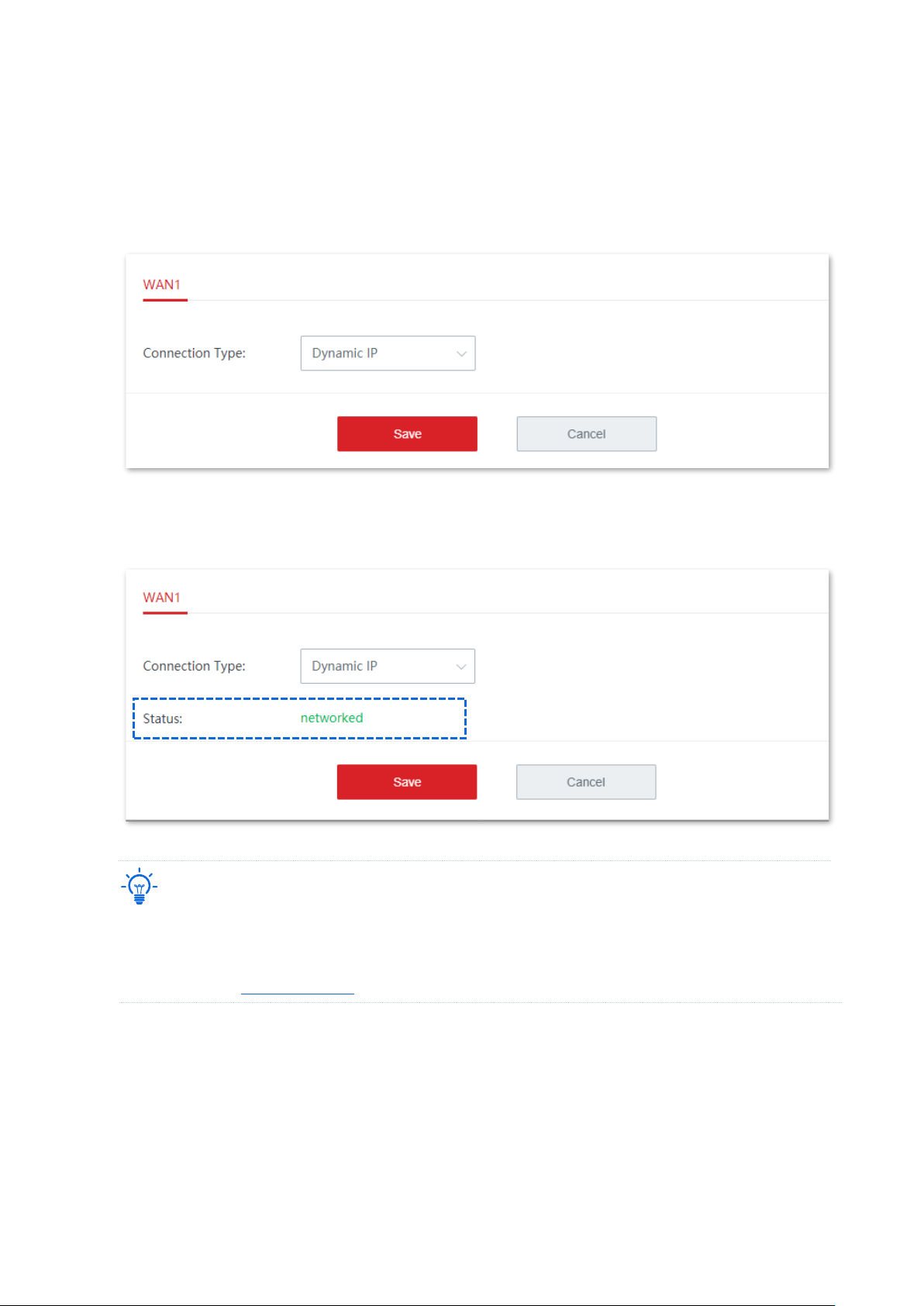
Dynamic IP
1. Click Internet Settings to enter the page.
2. Set Connection Type to Dynamic IP.
3. Click Save.
----End
The device connects to the internet successfully when the Status is displayed as networked.
Tip
If you fail to access the internet, please try the following solutions:
− Check whether the connection type you selected is correct.
− Try changing WAN parameters.
Page 36
Version 1.0
29
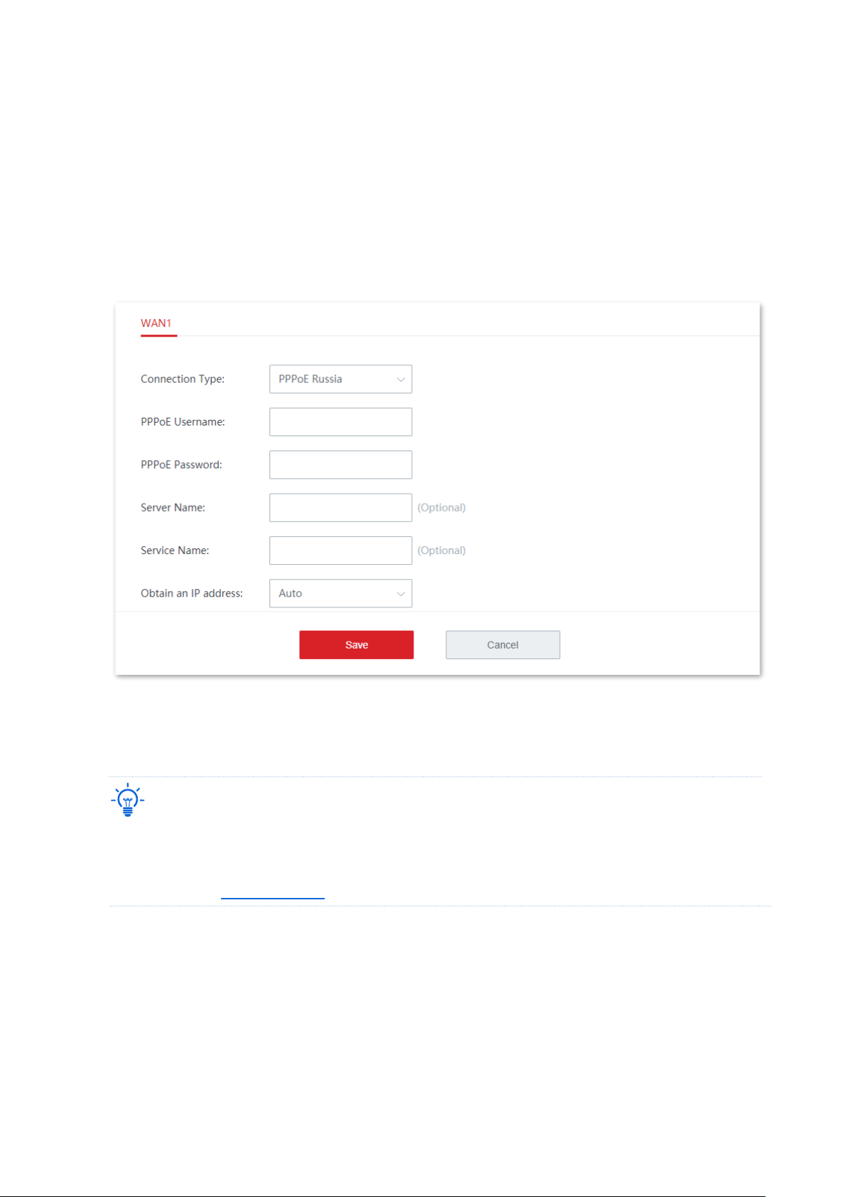
PPPoE Russia
1. Click Internet Settings to enter the page.
2. Set Connection Type to PPPoE Russia.
3. Enter the PPPoE Username, PPPoE Password provided by your ISP. If the Server Name,
Service Name, IP Address and other related parameters are also provided, enter them in the
corresponding input box as well.
4. Click Save.
----End
The device connects to the internet successfully when the Status is displayed as networked.
Tip
If you fail to access the internet, please try the following solutions:
− Check whether the parameters you entered are correct.
− Try changing WAN parameters.
Page 37
Version 1.0
30
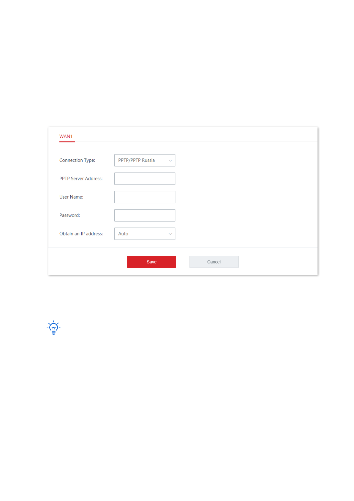
PPTP/PPTP Russia
1. Click Internet Settings to enter the page.
2. Set Connection Type to PPTP/PPTP Russia.
3. Enter the PPTP Server Address, User Name, and Password provided by your ISP. If the IP
Address and related parameters are also provided, enter them in the corresponding input box
as well.
4. Click Save.
----End
The device connects to the internet successfully when the Status is displayed as networked.
Tip
If you fail to access the internet, please try the following solutions:
− Check whether the parameters you entered are correct.
− Try changing WAN parameters.
Page 38
Version 1.0
31
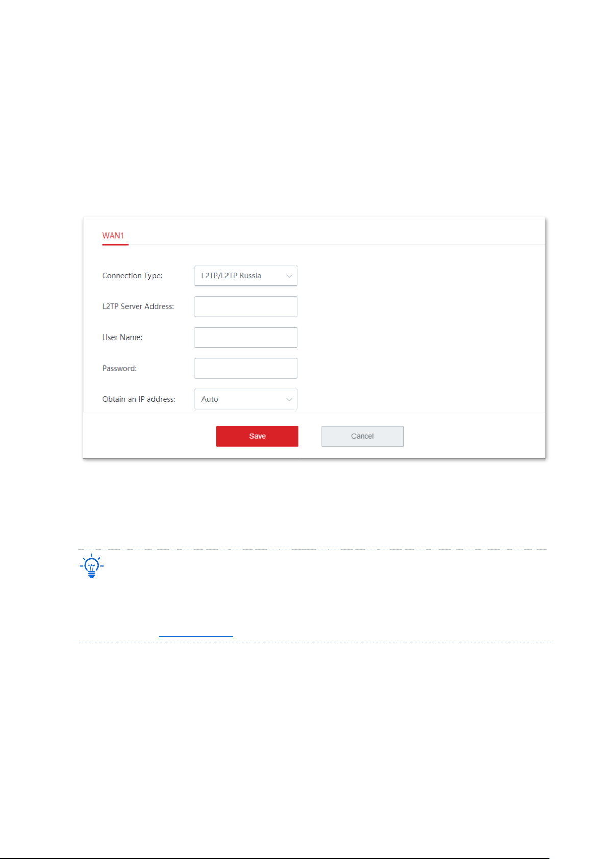
L2TP/L2TP Russia
1. Click Internet Settings to enter the page.
2. Set Connection Type to L2TP/L2TP Russia.
3. Enter the L2TP Server Address, User Name, and Password provided by your ISP. If the IP
Address and related parameters are also provided, enter them in the corresponding input box
as well.
4. Click Save.
----End
Wait for the device to complete rebooting. The device connects to the internet successfully
when the Status is displayed as networked.
Tip
If you fail to access the internet, please try the following solutions:
− Check whether the parameters you entered are correct.
− Try changing WAN parameters.
Page 39
Version 1.0
32
3.2.2 WAN parameters
If you have set internet connection parameters but your LAN devices cannot access the
internet still, try modifying WAN port parameters here.
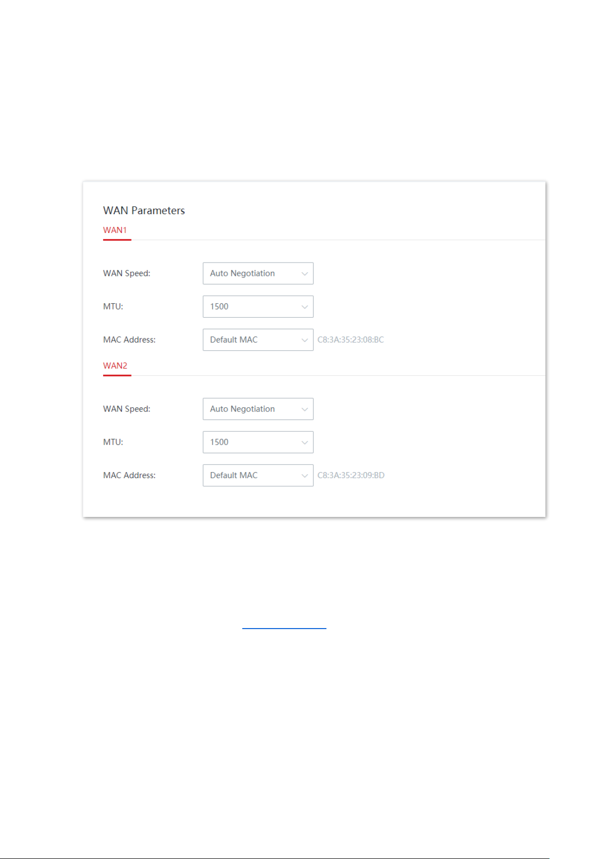
Click Internet Settings > WAN Parameters to enter the page.
WAN speed
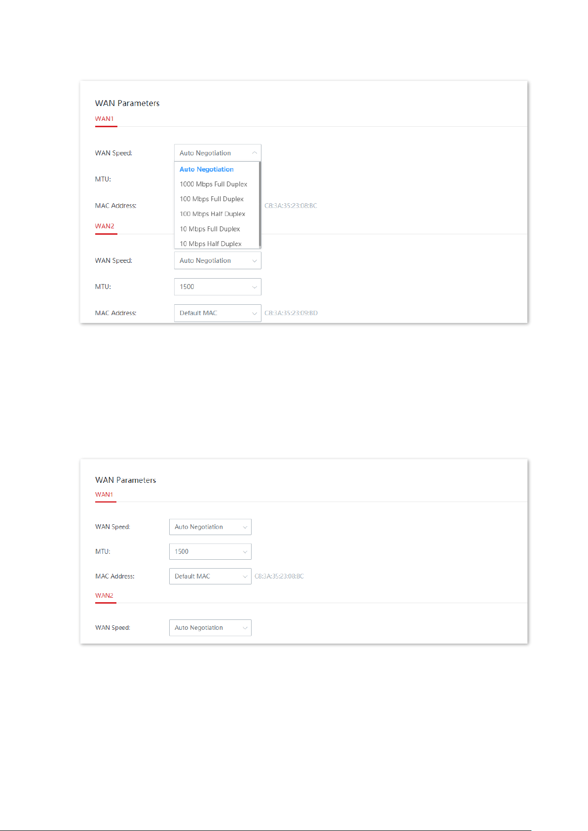
By default, the WAN speed of cable-free nodes is set to Auto Negotiation, which is
appropriate for almost all cases. If the WAN port is properly connected and the Ethernet
cable is not damaged, but in the Internet Settings module, the WAN port is still in grey color.
In this case, you can change the WAN speed to 10 Mbps Full Duplex or 10 Mbps Half Duplex
to fix the problem.
Otherwise, you are recommended to retain the default option Auto Negotiation.
Page 40
Version 1.0
33
MTU
MTU is abbreviated for Maximum Transmission Unit. It specifies the maximum size of a
packet that can be transmitted by a network device. If your connection type is PPPoE or
PPPoE Russia, the default MTU value is 1492. If your connection type is Static IP or Dynamic IP,
the default MTU value is 1500.
In general, it is recommended to retain the default option for the MTU value unless you
encounter the following conditions:
− You can neither access some websites nor open security sites (such as online banking
websites or PayPal).
Page 41
Version 1.0
34
− You can neither send nor receive Emails, or access servers such as FTP and POP
servers.
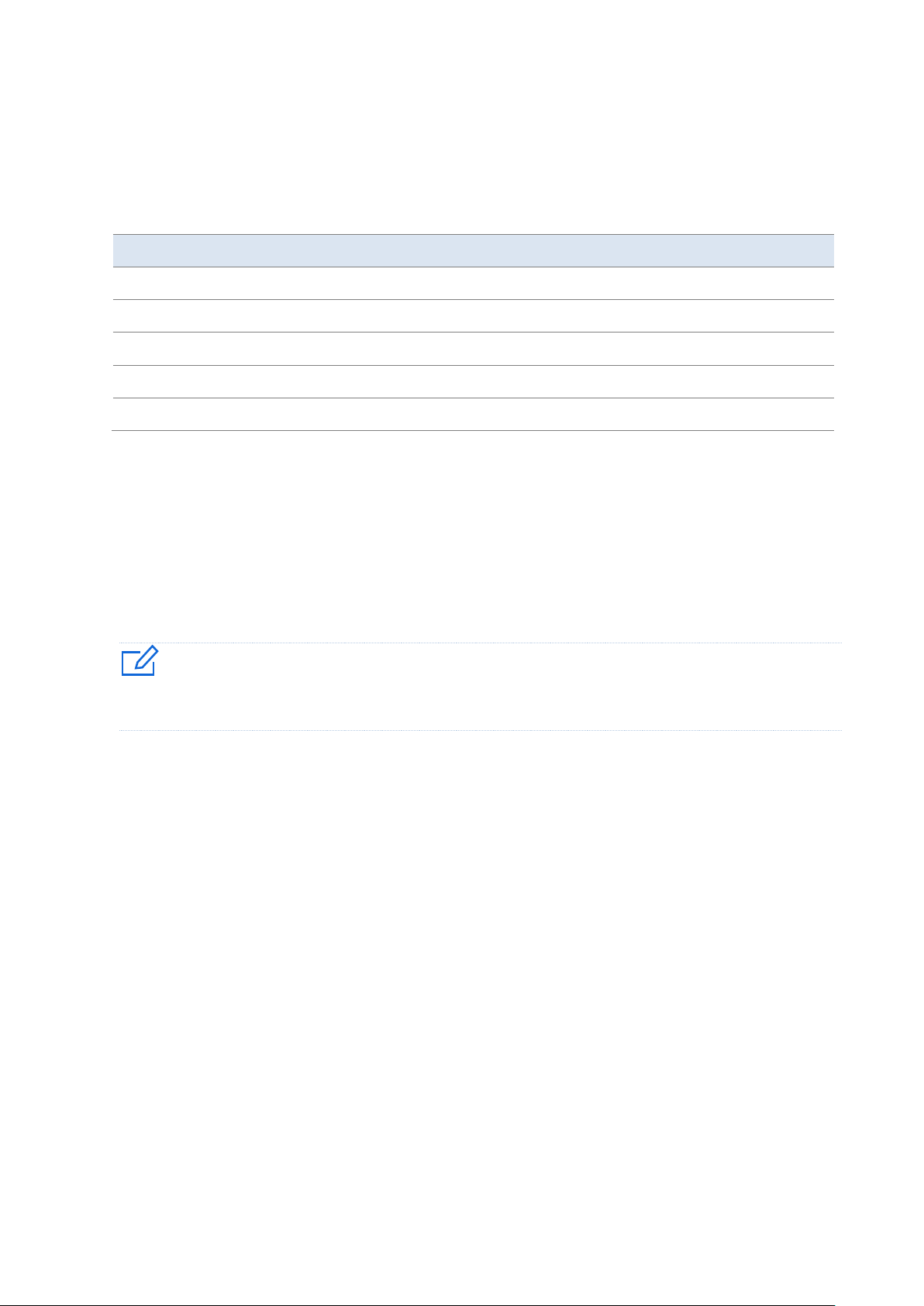
In this case, you can try gradually reducing the MTU value (recommended range: 1400 to
1500) to fix the problem.
MTU Value
Scenario
1500
It is the most common value for non-PPPoE connections and non-VPN connections.
1492
It is used for PPPoE connections.
1480
It is the maximum value for the ping function.
1450
It is used for DHCP, which assigns dynamic IP addresses to connected devices.
1400
It is used for VPN.
MAC address
If the device still fails to access the internet after you completed internet settings
configurations, probably the ISP bound the internet account with a MAC address (physical
address). In this case, you can try MAC address cloning (method 1 or method 2) to fix the
problem.
Note
Please clone the MAC address of the computer or the MAC address of the WAN port of the router on which
you set up the dial up internet connection.
Method 1: Use the computer on which you set up the dial up internet connection
for cloning
1. Use an Ethernet cable to connect the computer on which you set up the dial up internet
connection to the cable-free network.
2. Start a web browser on the computer, and visit 192.168.5.1.
3. Log in to the web UI of the cable-free node (router mode) and navigate to Internet Settings >
WAN Parameters.
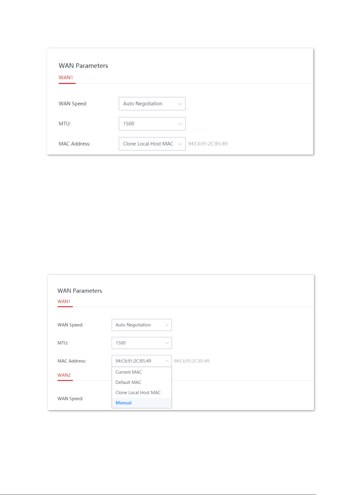
4. Select Clone Local Host MAC for MAC Address.
5. Click Save.
Page 42
Version 1.0
35
----End
Method 2: Use another device for cloning
1. Record the correct MAC address.
2. Log in to the web UI of the cable-free node (router mode) and navigate to Internet Settings >
WAN Parameters.
3. Click the MAC Address drop-down list and select Manual, enter the correct MAC address
(“the MAC address of the computer which directly connects to the Ethernet jack and has
internet availability” or “the MAC address of the WAN port of the router on which you set up
the dial up internet connection”).
4. Click Save.
----End
Page 43
Version 1.0
36
Tip
If you want to restore the MAC address of the WAN port to the default MAC address, navigate to Internet
Settings > WAN Parameters, click the MAC Address drop-down list, select Default MAC, and click Save.
3.2.3 LAN settings
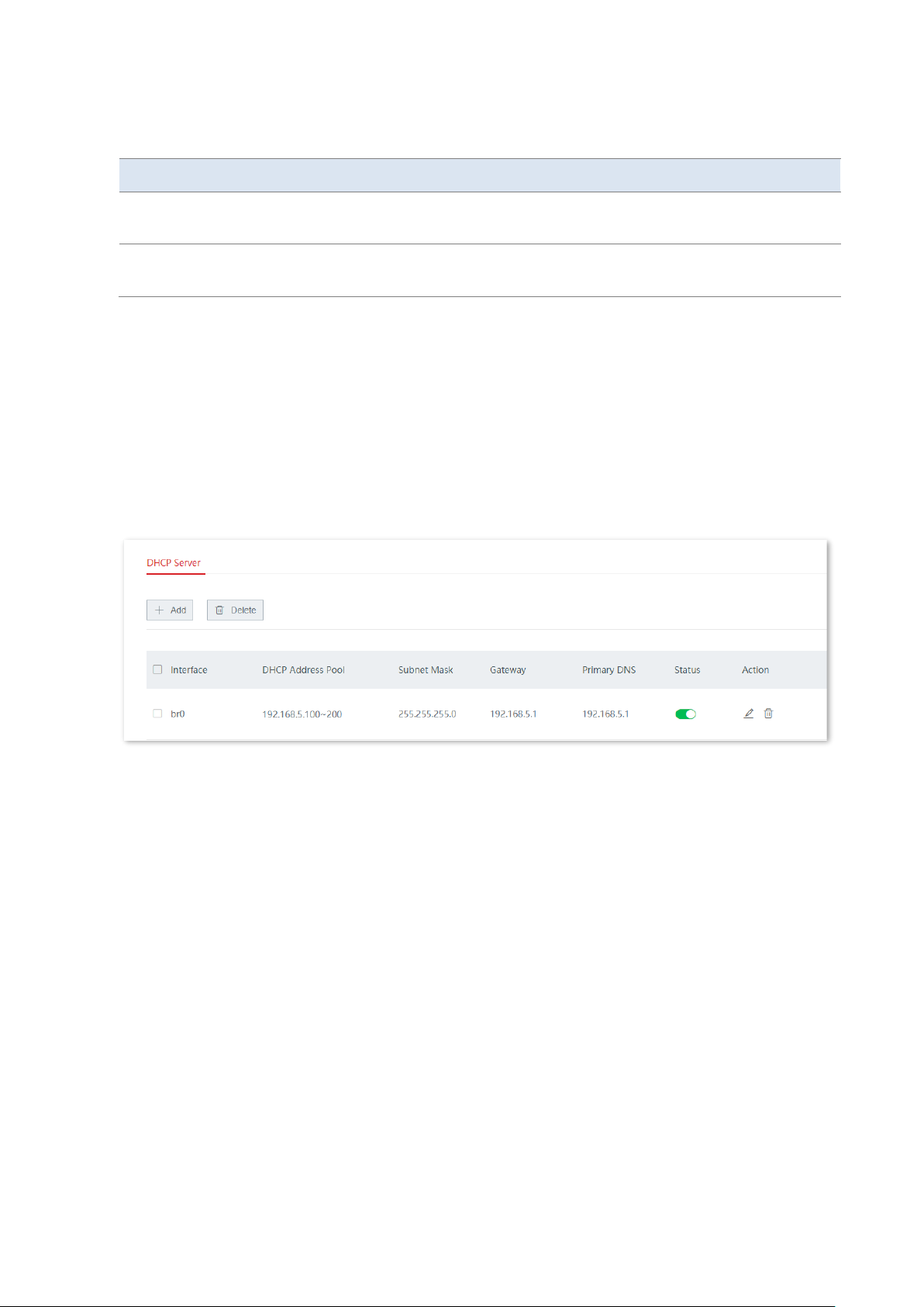
On the Internet Settings > LAN Settings page, you can check the LAN IP configuration of the
device and configure the DHCP server.
Click Internet Settings > LAN Settings to enter the page.
LAN IP
The LAN IP is the LAN IP address of the node and also the management IP address of the
node. The default LAN IP is 192.168.5.1 and the subnet mask is 255.255.255.0
Generally, you do not need to modify LAN settings unless an IP address conflict occurs. For
example, if the WAN port IP address obtained by the node and its LAN port IP address are on
the same network segment; or, the IP address of another device in the LAN is also
192.168.5.1.
After the LAN port IP address is modified, you will be automatically redirected to the login
page. If not, please verify that the IP address of the management host is set to Obtain an IP
address automatically and Obtain DNS server address automatically, and then try again to
access the new LAN port IP address.
Tip
If the new LAN port IP address is not on the same network segment as the original LAN port IP address, the
system will automatically match and modify the DHCP address pool to make it on the same network
segment as the new LAN port IP address.
Page 44
Version 1.0
37
Parameter description
Parameter
Description
LAN IP Address
It specifies the IP address of the LAN port of the device, which can be used to log in
to its web UI. The default IP address is 192.168.5.1.
Subnet Mask
It specifies the subnet mask of the LAN port of the device. The default subnet mask
is 255.255.255.0.
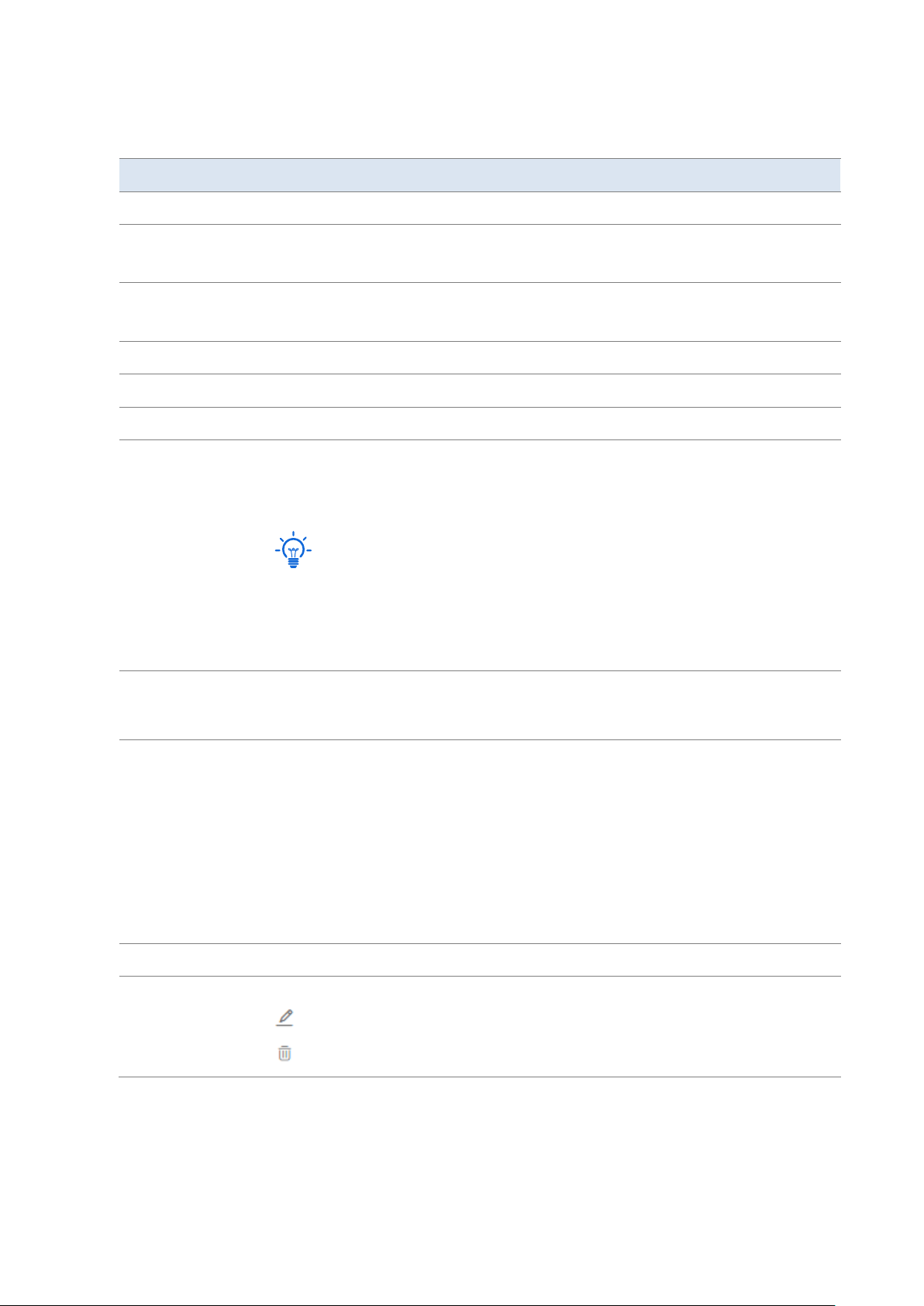
DHCP server
DHCP server can automatically assign IP address, subnet mask, gateway address, DNS and
other Internet information to user devices of the LAN.
If you disable DHCP server, you need to manually configure the IP address information on the
LAN device to access the Internet. Please keep the DHCP server enabled if there is no special
case.
Click + Add to add a DHCP server and click Delete to delete a DHCP server.
Page 45
Version 1.0
38
Parameter description
Parameter
Description
Interface
It specifies the interface of the DHCP server.
Start IP
It specifies the start IP address of the DHCP address pool.
By default, it is 192.168.5.31.
End IP
It specifies the end IP address of the DHCP address pool.
By default, it is 192.168.5.200.
DHCP Address Pool
It specifies the address range of the DHCP address pool (the assignable addresses).
Subnet Mask
It specifies the subnet mask assigned by the DHCP server to clients.
Gateway
It specifies the default gateway address assigned by the DHCP server to clients.
Primary DNS
It specifies the primary DNS server IP address assigned by the DHCP server to
clients. The cable-free node (router mode) supports DNS proxy function, and the
primary DNS address is the LAN IP address of the node by default.
Tip
Generally, you are recommended to keep the default setting.
If it is necessary to change the default setting, please set this parameter to a correct
DNS server IP address or DNS proxy IP address, to enable clients to access the
internet.
Secondary DNS
It specifies the secondary DNS server IP address assigned by the DHCP server to
clients. This parameter is optional. If it is empty, the DHCP server does not assign it
to clients.
Lease Time
It specifies the validity period of the assigned IP address, which is 30 minutes by
default.
When half of the lease time has elapsed, the client sends a DHCP request to the
DHCP server to renew the lease time. If the request succeeds, the lease time is
extended according to the request. Otherwise, the client sends the request again
when 7/8 of the lease time has elapsed. If the request succeeds, the lease time is
extended according to the request. Otherwise, the client must request an IP
address from the DHCP server after the lease time expires.
It is recommended that you retain the default value.
Status
It specifies the status of the DHCP server. You can toggle it on or off as required.
Action
It specifies the operations you can perform on the DHCP server.
: Click it to edit the DHCP server.
: Click it to delete the DHCP server. The default DHCP server cannot be deleted.
Page 46

Version 1.0
39
3.2.4 VLAN settings
Overview
VLAN, abbreviated for Virtual Local Area Network, is a technology which divides LAN devices
into different network segments logically rather than physically to create virtual work groups.
It is used to divide the work stations in the switch-formed network into logical groups among
which broadcast is isolated. Work stations in a group belong to a same VLAN and can
communicate like they are connected to a same network segment no matter where they
physically are. However, due to the isolation of broadcast packets, the VLAN cannot
communicate with each other and packets must be forwarded by a router or other layer 3
packet forwarding devices.
Compared with the traditional Ethernet, VLAN has the following advantages:
− Control the range of broadcast domain: Broadcast messages in the LAN are restricted
in a VLAN, which saves bandwidth and improves network processing capability.
− Enhance the security of the LAN: Because messages are isolated in the data link layer
by the broadcast domain divided by VLAN, the host in each VLAN cannot directly
communicate with each other and messages have to be forwarded by a router or
other layer 3 network devices.
− Create virtual work groups freely: VLAN can create virtual work groups irrespective of
physical network range. A user can still access the network without having to change
network configurations as long as he or she remains within the virtual work group
even if his or her physical location changed.
Add VLAN
The cable-free device supports IEEE 802.1q VLAN, which can be used in the network
environment where QVLAN is divided.
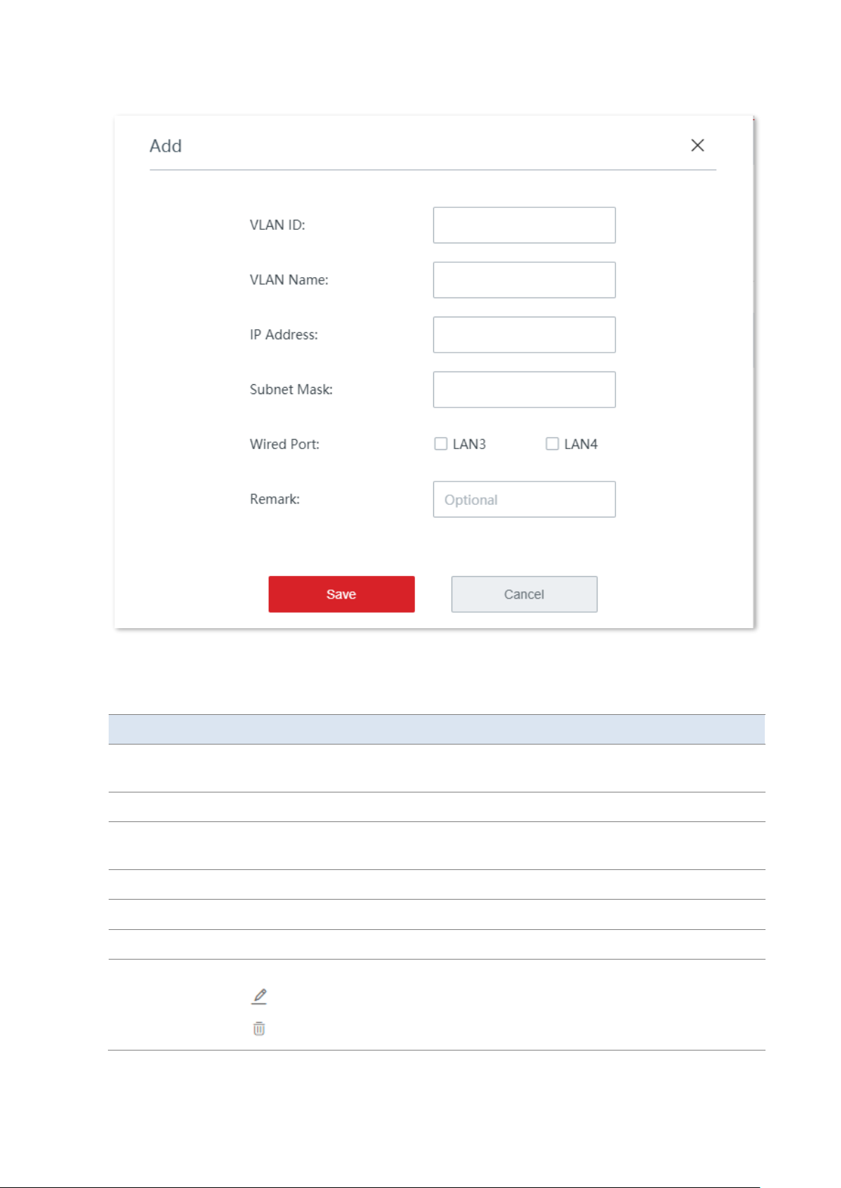
1. Click Internet Settings > VLAN Settings.
2. Click + Add.
3. Configure a VLAN rule in the pop-up window.
4. Click Save.
Page 47
Version 1.0
40
----End
Parameter description
Parameter
Description
VLAN ID
It specifies the identifier of the VLAN, which is used to divide separate VLANs in a
LAN. Different IDs stand for different VLANs.
VLAN Name
It specifies the name of the VLAN interface.
IP Address
It specifies the IP address of the VLAN interface and devices connected to the
interface can use this IP address to log in to the web UI of the router.
Subnet Mask
It specifies the subnet mask of the VLAN interface.
Wired Port
It specifies the physical port supported by the VLAN.
Remark
It specifies the remarks of the VLAN.
Action
It specifies the operations you can perform on the rule.
: Click it to edit the rule.
: Click it to delete the rule.
Page 48
Version 1.0
41
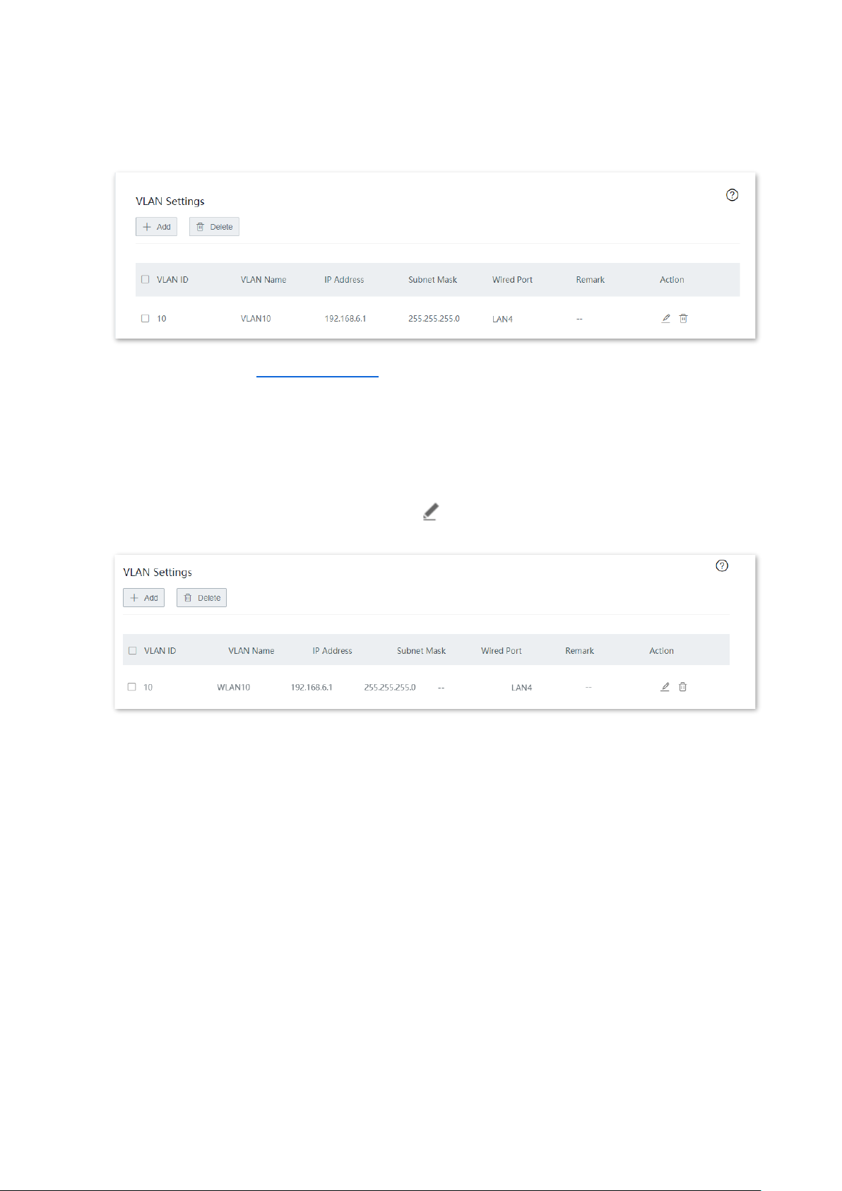
After the VLAN is added successfully, you can view the added VLAN on the Internet Settings >
VLAN Settings page. See the following figure.
Besides, you need to set a DHCP server for the VLAN, so as to enable clients under the VLAN to
automatically obtain IP address from the node to access the internet.
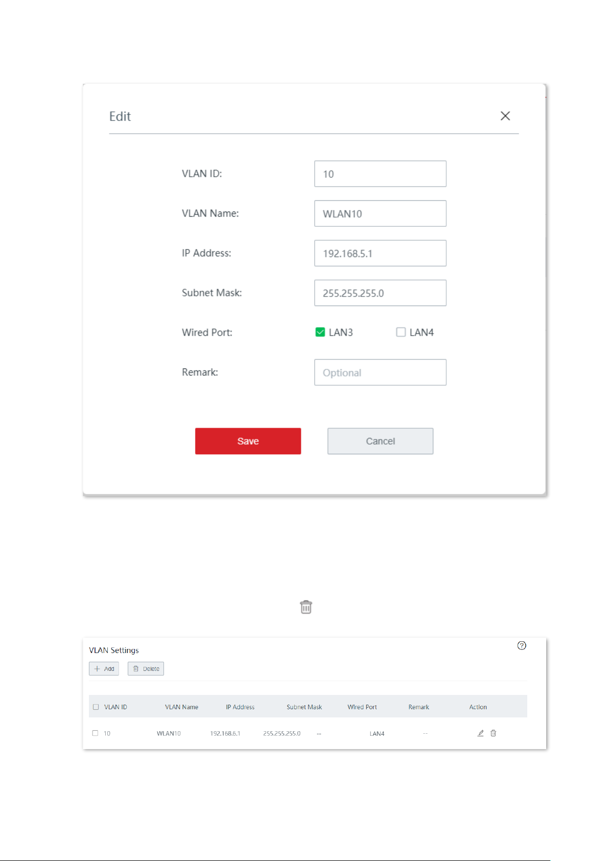
Modify VLAN
1. Click Internet Settings > VLAN Settings.
2. Locate the VLAN rule to be modified and click .
3. Modify parameters.
4. Click Save.
Page 49
Version 1.0
42
----End
Delete VLAN
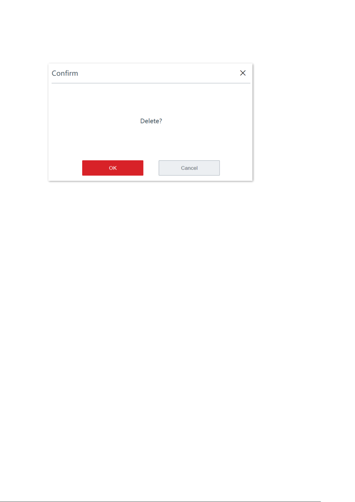
1. Click Internet Settings > VLAN Settings.
2. Locate the VLAN rule to be deleted and click .
Page 50
Version 1.0
43
3. Click OK after confirming the pop-up reminder.
----End
Page 51
Version 1.0
44
3.3 Wireless
On this page, you can change the wireless configurations of the cable-free primary node.
The device supports tri-band WiFi networks at most. By default, the device adopts wireless
networking with one 5 GHz band exclusively used to establish a cable-free link, and the 2.4
GHz band and the other 5 GHz band used for client access.
3.3.1 Wireless settings
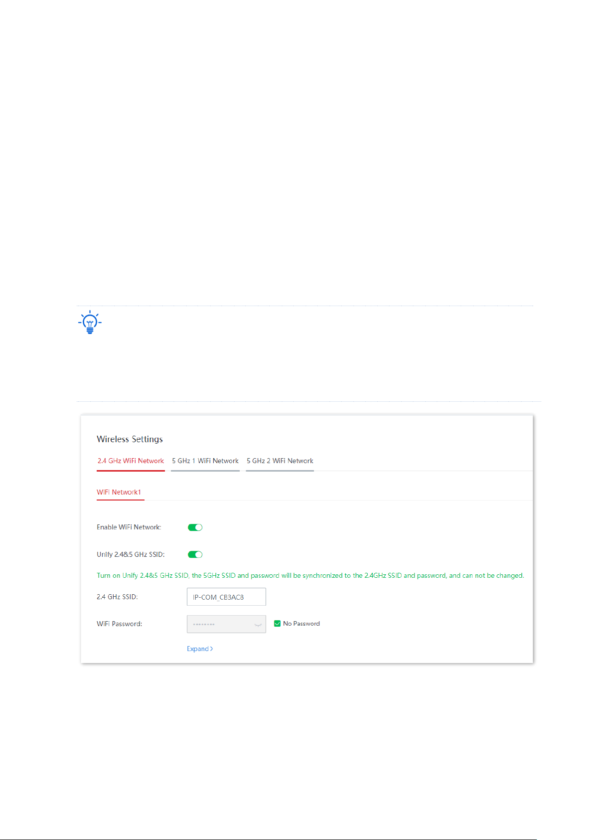
On this page, you can configure the basic wireless parameters, including enable/disable WiFi
networks, change the WiFi network name, set the WiFi password and other parameters.
Click Wireless > Wireless Settings to enter the page.
Tip
The 2.4 GHz WiFi network 1 SSID (WiFi name) and WiFi password have been set as the default SSID policy.
The configuration of 2.4 GHz WiFi network 1 SSID and WiFi password will be synchronized to other nodes
applied with the default SSID policy (By default, all secondary nodes are applied with the default SSID policy
in the cable-free network).
Page 52

Version 1.0
45
Parameter description
Parameter
Description
WiFi Network1/2/3/4
Every band of the node supports 4 WiFi networks and only WiFi network 1 is
enabled by default.
Enable WiFi Network
It is used to enable/disable the corresponding WiFi network.
Unify 2.4&5 GHz SSID
After this function is enabled, the 2.4 GHz WiFi network shares the same SSID
(WiFi network name) and WiFi password with the 5 GHz WiFi network, and
the parameters of the 5 GHz WiFi network on the Wireless Settings and Max
Rate & Isolation module automatically synchronize with those of the 2.4 GHz
WiFi network and cannot be changed separately. When a wireless client
connects to the cable-free device, it will be automatically connected to the
WiFi network with the best network quality.
Tip
If there are clients in your network which supports only the 2.4 GHz WiFi
network, to guarantee these devices can normally connect to the WiFi
network as well, you are recommended not to enable this function.
SSID
It specifies the WiFi network name of the corresponding WiFi network.
WiFi Password
It specifies the password of the corresponding WiFi network. For WiFi
network security, it is strongly recommended that you set a WiFi password.
No Password
It specifies that no WiFi password is set. Under such circumstances, the
corresponding WiFi network is open.
Hide SSID
After this function is enabled, the SSID will be hidden and will not appear in
the available network list of clients (such as smartphones), which enhances
the security of the WiFi network.
If you want to connect to a hidden WiFi network, manually enter the SSID on
your client.
Max. Clients
It specifies the maximum number of clients allowed to connect to the WiFi
network.
If this value is reached, new clients cannot connect to the WiFi network
unless some clients are disconnected.
VLAN ID
It specifies the VLAN ID of the WiFi network.
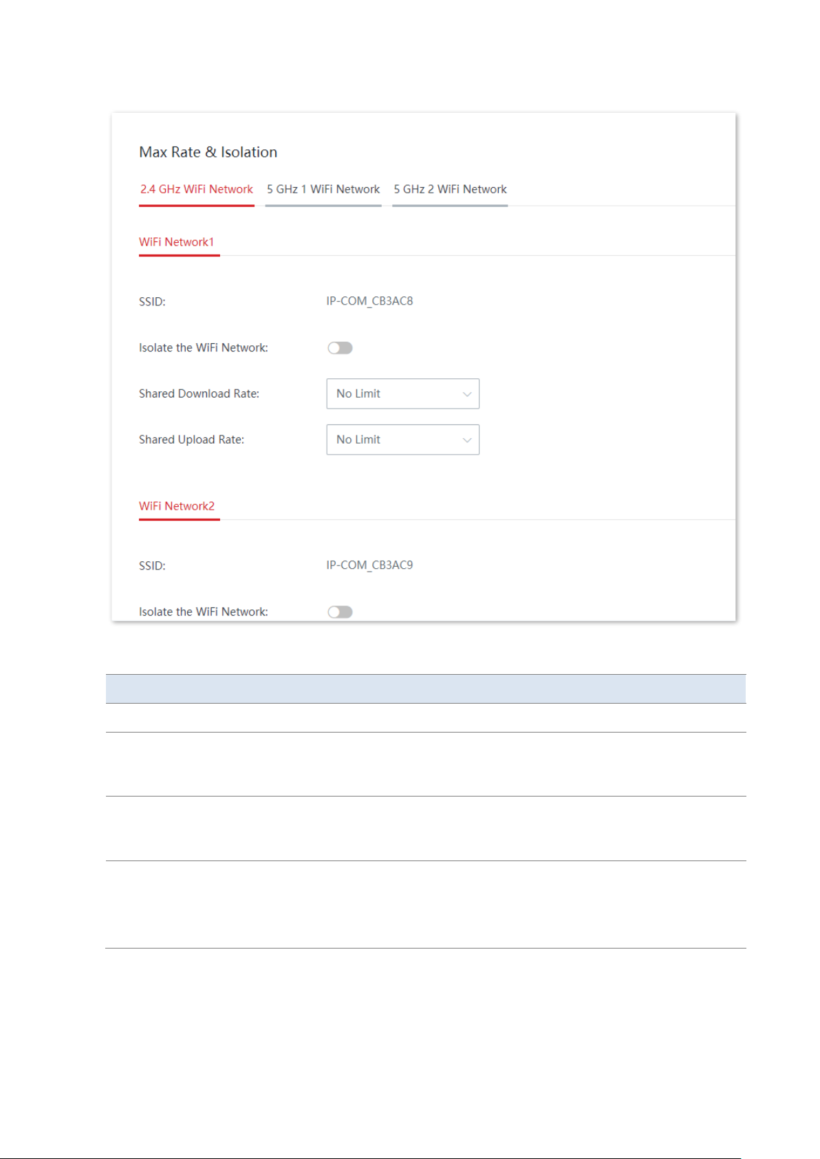
3.3.2 Max rate & isolation
On this page, you can configure the maximum rate and isolation. This function is disabled by
default.
Click Wireless > Max Rate & Isolation to enter the page.
Page 53
Version 1.0
46
Parameter description
Parameter
Description
SSID
It specifies the WiFi network name of the node.
Isolate the WiFi Network
After this function is enabled, clients connected to this WiFi network cannot
communicate with clients connected to other WiFi networks of the cable-free
system, thus enhancing the security of WiFi networks.
Shared Upload/Download
Rate
It specifies the maximum upload/download rate shared by clients connected
to the WiFi network. No Limit means to set no limit on the maximum
upload/download rate of the WiFi network.
No Access to LAN
This function is valid only for WiFi Network2/3/4.
After this function is enabled, clients connected to the WiFi network can
access only the internet, and can access neither the LAN nor the web UI of
the node.
Page 54
Version 1.0
47
3.3.3 MAC filters
Overview
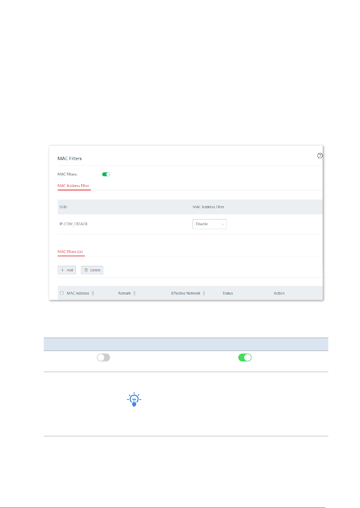
On this page, you can allow or forbid WiFi network access from specified clients by setting
MAC filter rules. By default, this function is disabled.
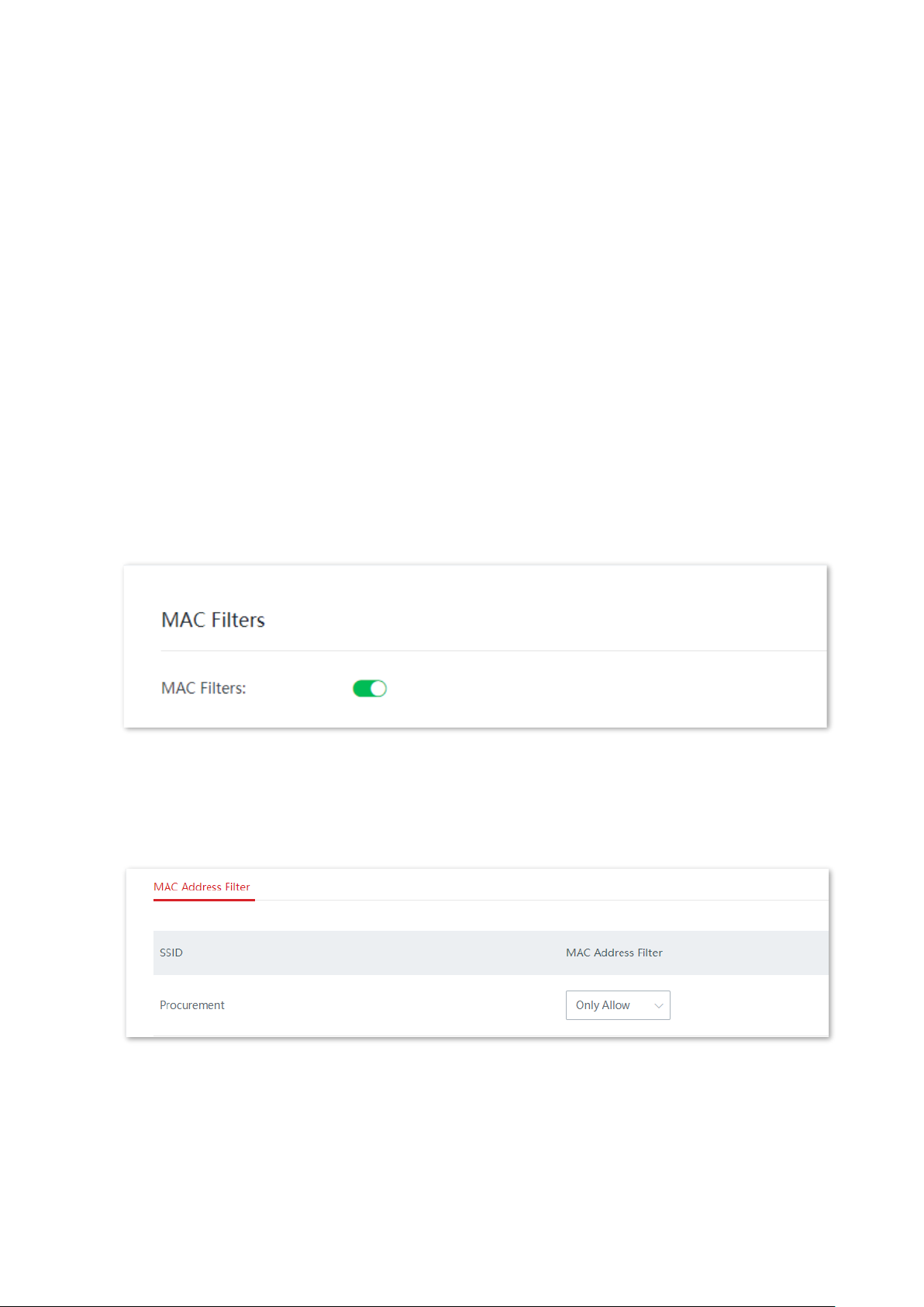
Click Wireless > MAC Filters to enter the page. The following displays the page when the
function is enabled.
Click + Add to add a MAC filters rule and click Delete to delete a MAC filters rule.
Parameter description
Parameter
Description
MAC Filters
specifies the MAC filters function is disabled and specifies the MAC filters
function is enabled.
MAC Address
Filter
SSID
It specifies the name of the enabled WiFi network of the node.
Tip
By default, the SSID of 2.4 GHz WiFi network, 5 GHz 1 WiFi network, and 5
GHz 2 WiFi network is the same. Therefore, only one SSID is displayed by
default.
Page 55
Version 1.0
48
Parameter
Description
MAC
Address
Filter
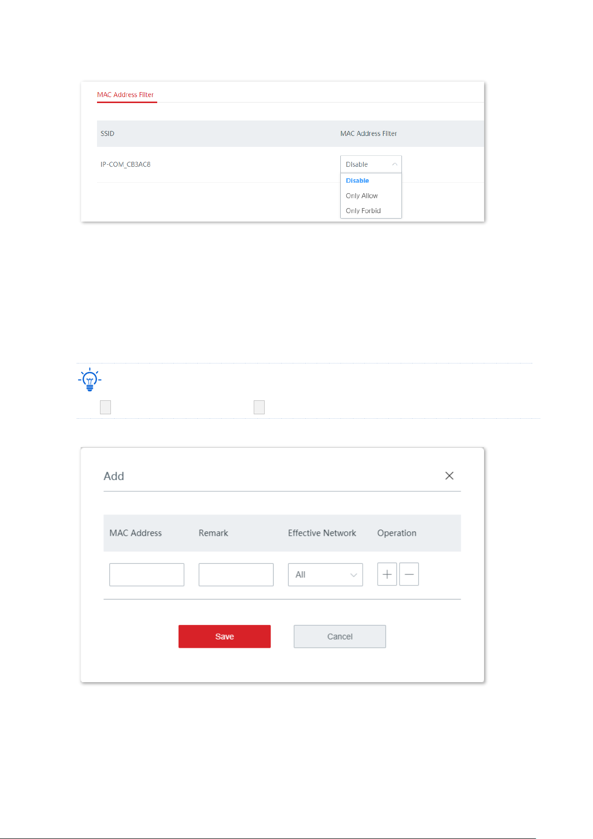
It specifies the MAC address filter mode.
−
Disable: It specifies that the MAC address filter function is not
enabled on the WiFi network and all wireless clients are allowed to
connect to the WiFi network.
−
Only Allow: It specifies that only the wireless clients in the MAC
Filters List are allowed to connect to the WiFi network.
−
Only Forbid: It specifies that only the wireless clients in the MAC
Filters List are forbidden to connect to the WiFi network. Other
wireless clients can connect to the WiFi network.
MAC Filters List
MAC
Address
It specifies the MAC address of the wireless client.
Remark
It specifies the remarks of the MAC address.
Effective
Network
It specifies the WiFi network on which the rule takes effect.
Status
It specifies the status of the rule. You can enable or disable the rule as
required.
Action
It specifies the operations you can perform on the rule.
: Click it to edit the rule.
: Click it to delete the rule.
Set MAC filters rule
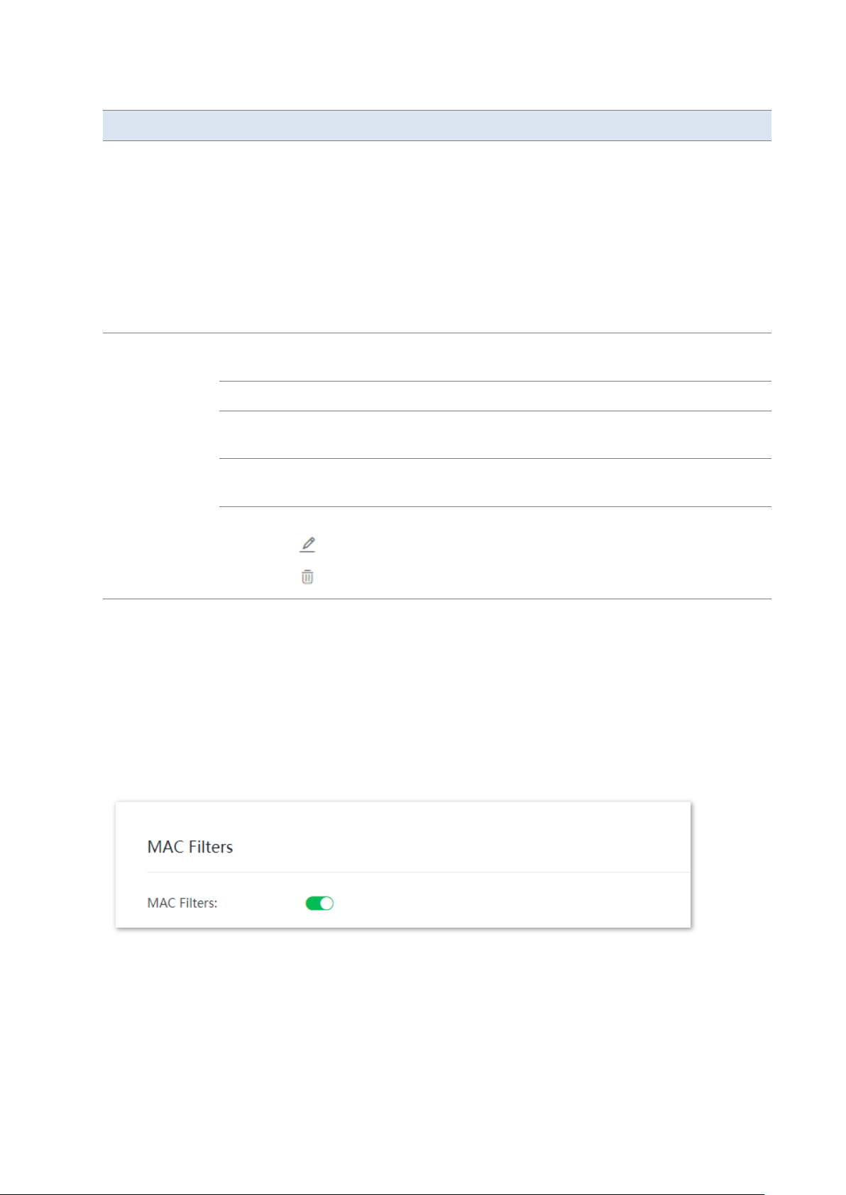
Enable the MAC filters function
1. Click Wireless > MAC Filters.
2. Toggle on MAC Filters.
3. Click Save.
Set MAC address filter mode
1. Select the appropriate MAC Address Filter mode as required.
2. Click Save.
Page 56
Version 1.0
49
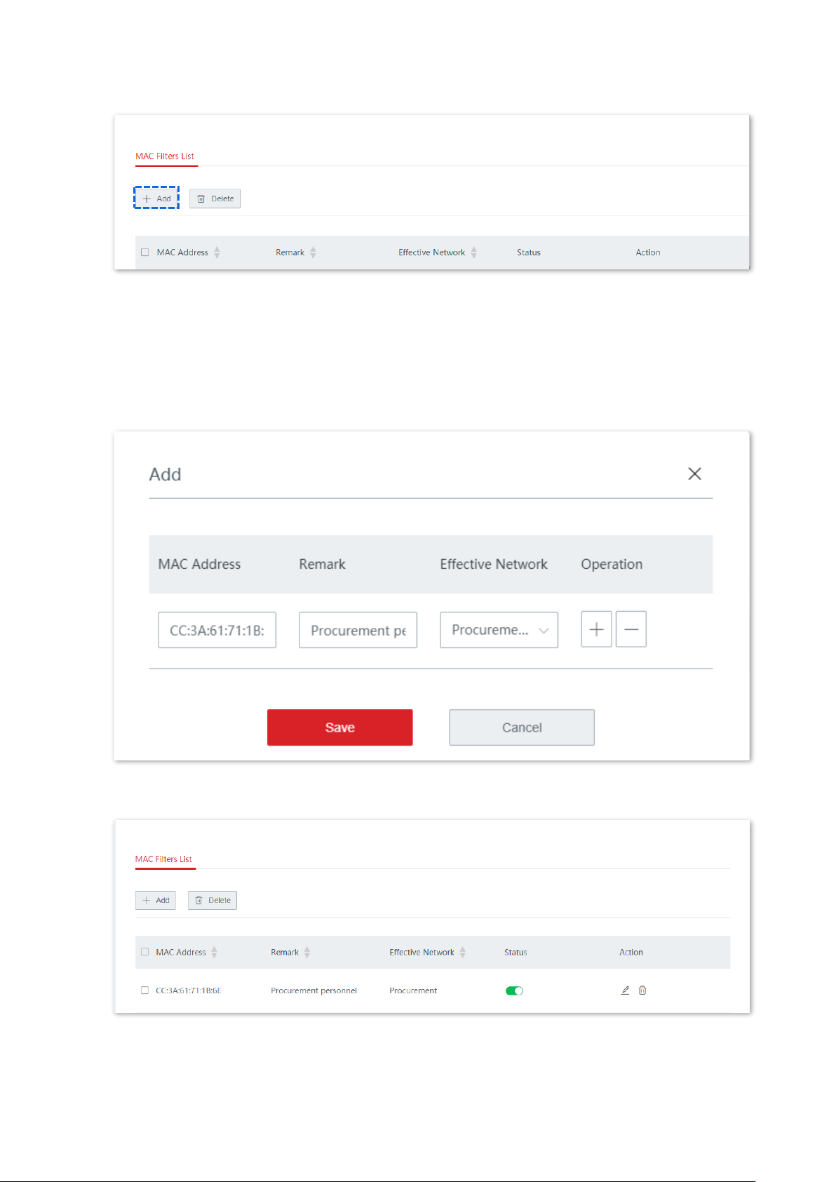
Add a MAC filter rule
1. Click + Add to enter the configuration page.
2. Add a MAC filter rule.
(1) Enter the MAC address of the wireless client on which the MAC filter rule applies.
(2) (Optional) Set a remark for the MAC address.
(3) Select a WiFi network on which the MAC filter rule takes effect.
Tip
Click + to add a MAC filter rule and click – to delete an unsaved MAC filter rule.
3. Click Save.
----End
You can check the newly added MAC filter rule on the Wireless > MAC Filters page.
Page 57
Version 1.0
50
Example of configuring MAC filters rule
Network requirement
An enterprise uses cable-free devices to set up a network.
Requirement: Only a procurement personnel is allowed to connect to the WiFi network
(Procurement) of the cable-free primary node for internet access.
Solution
The MAC filters function can meet this requirement. Assume that the physical address of the
computer of the procurement personnel is CC:3A:61:71:1B:6E.
Configuration procedures
1. Click Wireless > MAC Filters.
2. Enable the MAC filters function.
(1)
Toggle on MAC Filters.
(2)
Click Save.
3. Set the MAC address filter mode.
(1)
Select a MAC Address Filter mode for the WiFi network “Procurement”, which is “Only
Allow” in this example.
(2)
Click Save.
4. Add a MAC filter rule.
(1) Click + Add.
Page 58
Version 1.0
51
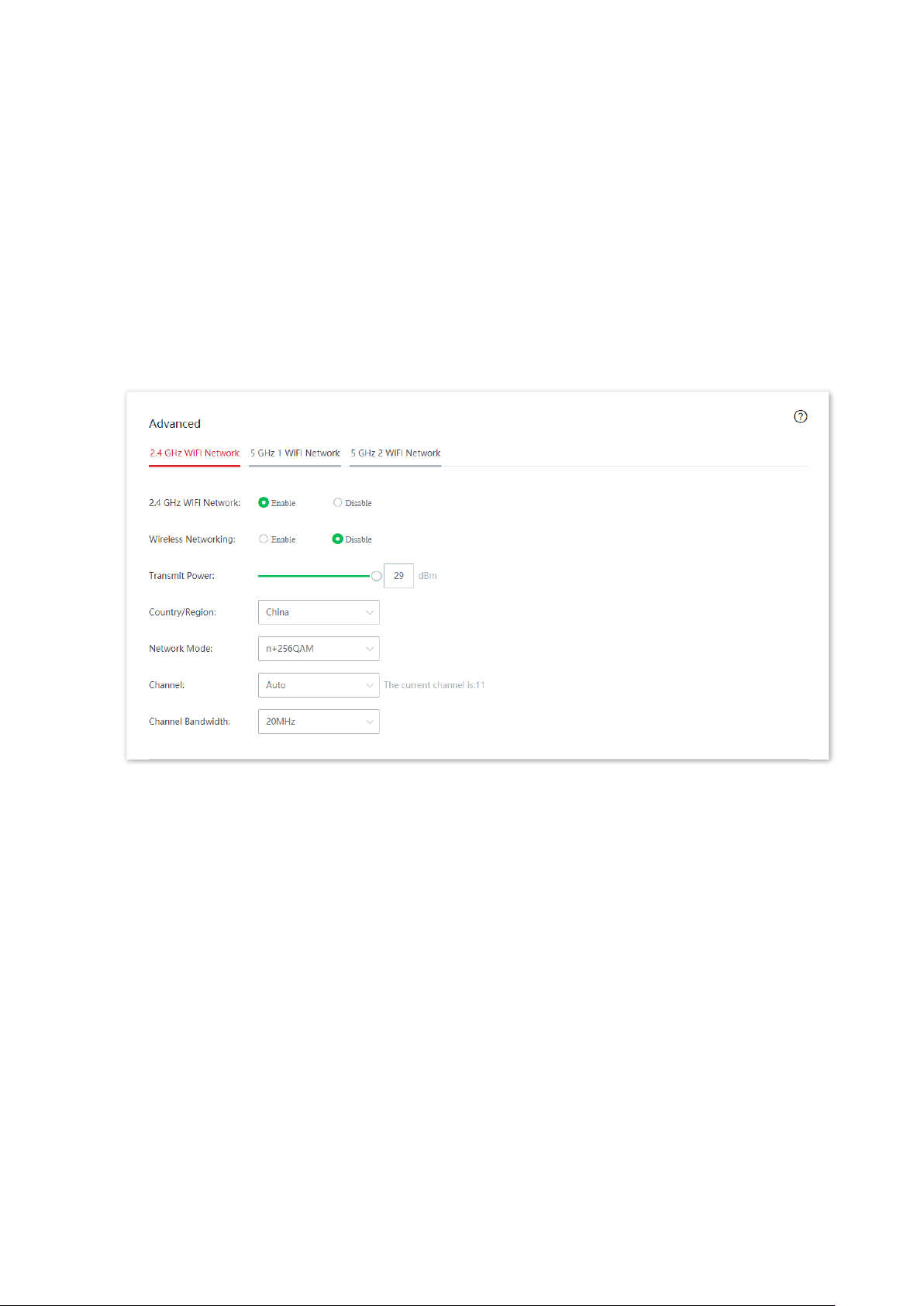
(2) On the Add configuration window, set the following parameters:
− Enter CC:3A:61:71:1B:6E in the MAC Address input box.
− Enter Procurement personnel in the Remark input box.
− Select Procurement from the drop-down list of Effective Network.
(3) Click Save.
Added successfully. See the following figure.
----End
Page 59
Version 1.0
52
Verification
Only the before-mentioned wireless client can connect to the WiFi network “Procurement”
while other clients are blocked.
3.3.4 Advanced
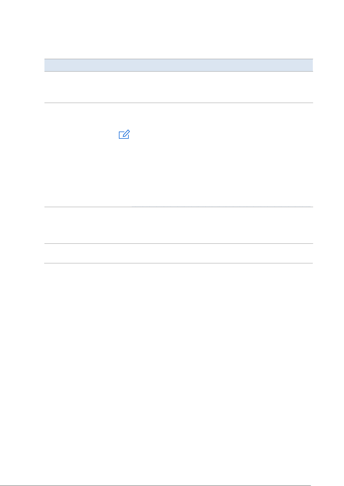
On this page, you can set the advanced wireless settings, such as transmit power, network
mode, channel, and channel bandwidth.
Click Wireless > Advanced to enter the page.
Page 60
Version 1.0
53
Parameter description
Parameter
Description
2.4 GHz/5 GHz WiFi
Network
It is used to enable or disable the WiFi function of the corresponding band.
Wireless Networking
After this function is enabled, the router can use this band to perform
wireless networking.
Note
If the wireless networking function is enabled on more than one band, the
router will perform load balancing and network accordingly; therefore, the
networking performance of the cable-free system is improved, but the
capacity is reduced. Please choose the appropriate band to enable the
wireless networking function. Below are some suggestions:
− Capacity-oriented: Enable the function only on the 5 GHz 2 band.
− Coverage-oriented: Enable the function on both the 2.4 GHz and 5
GHz 1 bands.
Transmit Power
It specifies the transmit power of the corresponding band.
The higher the transmit power, the wider the WiFi coverage. However, an
appropriate reduction of transmit power can help improve the performance
and security of the WiFi network.
Country/Region
It specifies the country or region where the node is located. Please select the
correct country or region.
Page 61

Version 1.0
54
Parameter
Description
Network Mode
It specifies the WiFi network mode of the corresponding band.
Network modes of the 2.4 GHz WiFi network include 11b, 11g, 11b/g,
11b/g/n, and n+256QAM. By default, the router works in the n+256QAM
mode.
−
11b: In this mode, only 802.11b wireless clients are allowed to access
the 2.4 GHz WiFi network.
−
11g: In this mode, only 802.11g wireless clients are allowed to access
the 2.4 GHz WiFi network.
−
11b/g: In this mode, 802.11b and 802.11g wireless clients can access
the 2.4 GHz WiFi network.
−
11b/g/n: In this mode, wireless clients compliant with 802.11b or
802.11g and wireless clients working at 2.4 GHz and compliant with
802.11n can access the 2.4 GHz WiFi network.
−
n+256QAM: Wireless clients compliant with 802.11b or 802.11g and
wireless clients working at 2.4 GHz and compliant with 802.11n can
access the 2.4 GHz WiFi network.
QAM, abbreviated for Quadrature Amplitude Modulation, is a
modulation scheme that moderates amplitude on two orthogonal
carriers. Using the orthogonality of sine wave and cosine wave, it
moderates two signals at the same time, improving the modulation
efficiency. In the n+256QAM network mode, the 256-QAM modulation
mode compliant with the IEEE 802.11ac standard can be used under
the IEEE 802.11n standard in the 2.4GHz band, which improves the
single stream rate from 150 Mbps to 200 Mbps.
Note: Such improvement can be realized only when the band is 2.4
GHz band, and the transmitting an d receiving ends both support the
n+256QAM network mode. If any one end does not support
n+256QAM, the single stream rate under the 2.4 GHz band is still 150
Mbps at most. Moreover, after the network mode is set to
n+256QAM, the stability and anti-interference capability of the
network will be reduced compared with the stability and antiinterference capability under other modes.
Network modes of the 5 GHz WiFi network include 11a, 11ac, and 11a/n
mixed. By default, the router works in the 11ac mode.
−
11a: In this mode, only 802.11a wireless clients are allowed to access
the 5 GHz WiFi network.
−
11ac: In this mode, only 802.11ac wireless clients are allowed to
access the 5 GHz WiFi network.
−
11a/n mixed: In this mode, wireless clients compliant with 802.11a
and wireless clients working at 5 GHz and compliant with 802.11n can
access the 5 GHz WiFi network.
Page 62

Version 1.0
55
Parameter
Description
Channel
It specifies the channel in which the wireless data is transmitted and
received. The available channels are determined by the current
country/region and wireless band.
Auto: The node automatically detects the occupation rate of channels and
selects the appropriate working channel accordingly.
If connection drop, freeze or slow internet occurs frequently when you are
using the WiFi network, you can try changing the working channel. You can
check the channels with low occupation rate and little interference using
software tools (such as WiFi analyzer).
Channel Bandwidth
It specifies the bandwidth of the working channel. A high channel bandwidth
means a higher transmission rate, but the penetration capability is reduced
and the transmission distance is shortened.
−
20MHz: The node uses the 20MHz channel bandwidth.
−
40MHz: The node uses the 40MHz channel bandwidth.
−
20MHz/40MHz: This channel bandwidth is available only for the 2.4
GHz only. The node automatically adjusts the channel bandwidth to
20MHz or 40MHz based on the surrounding environment.
−
80MHz: This channel bandwidth is available only for the 5 GHz only.
The node uses the 80MHz channel bandwidth.
RSSI Threshold
It specifies the minimum wireless signal strength can be received by the
band. Clients with a lower signal strength value cannot connect to the node.
When there are multiple nodes in the surroundings, an appropriate RSSI
value helps ensure wireless clients connects to the nodes with a stronger
signal.
Air Interface Scheduling
After this function is enabled, the node fairly allocates download
transmission time to clients, which guarantees that high-speed clients and
low-speed clients obtain the same download transmission time. In this way,
high-speed clients can transmit more data, achieving higher system
throughput and a larger number of accessed clients.
APSD
It is abbreviated for Automatic Power Save Delivery, which is the WMM
power-saving certification protocol of the WiFi Alliance. Enabling APSD can
reduce the power consumption of the node. By default, this function is
enabled.
Short GI
It specifies short guard interval for preventing data block interference. This
parameter is available only for the 2.4 GHz WiFi network.
When wireless signal is transmitted in space, delays may occur on the
receiving end due to multipath and other factors. If the succeeding data
block is transmitted too fast, it will cause interference to the preceding data
block, and short GI can be used to avoid this interference. When short GI is
enabled, wireless throughput is improved.
Page 63

Version 1.0
56
Parameter
Description
Deployment Mode
Choose a deployment mode based on the deployment intensity of nodes.
−
Capacity-oriented: This deployment mode is generally used in
scenarios where nodes are deployed intensively, such as meeting hall,
exhibition hall, banquet hall, gym, university classroom, and airport.
This mode can effectively reduce interferences between nodes.
−
Coverage-oriented: This deployment mode is generally used in
scenarios where nodes are deployed loosely, such as office,
warehouse, and hospital. This mode can expand the coverage of
nodes.
Client Timeout Interval
If a client generates no data communication within this interval after
connecting to the WiFi network, the node will cut this client off.
Mandatory Rate
By adjusting the mandatory rate and optional rate, you can limit access from
low-speed clients, thus improving the internet experience of other clients.
−
Mandatory Rate: It is a group of mandatory rates of the node. Clients
must support these mandatory rates; otherwise, the clients will fail to
access the WiFi network.
−
Optional Rate: It is a collection of other rates supported by the node
except for mandatory rates. These optional rates help clients realize
connection with the node at a higher rate.
Optional Rate
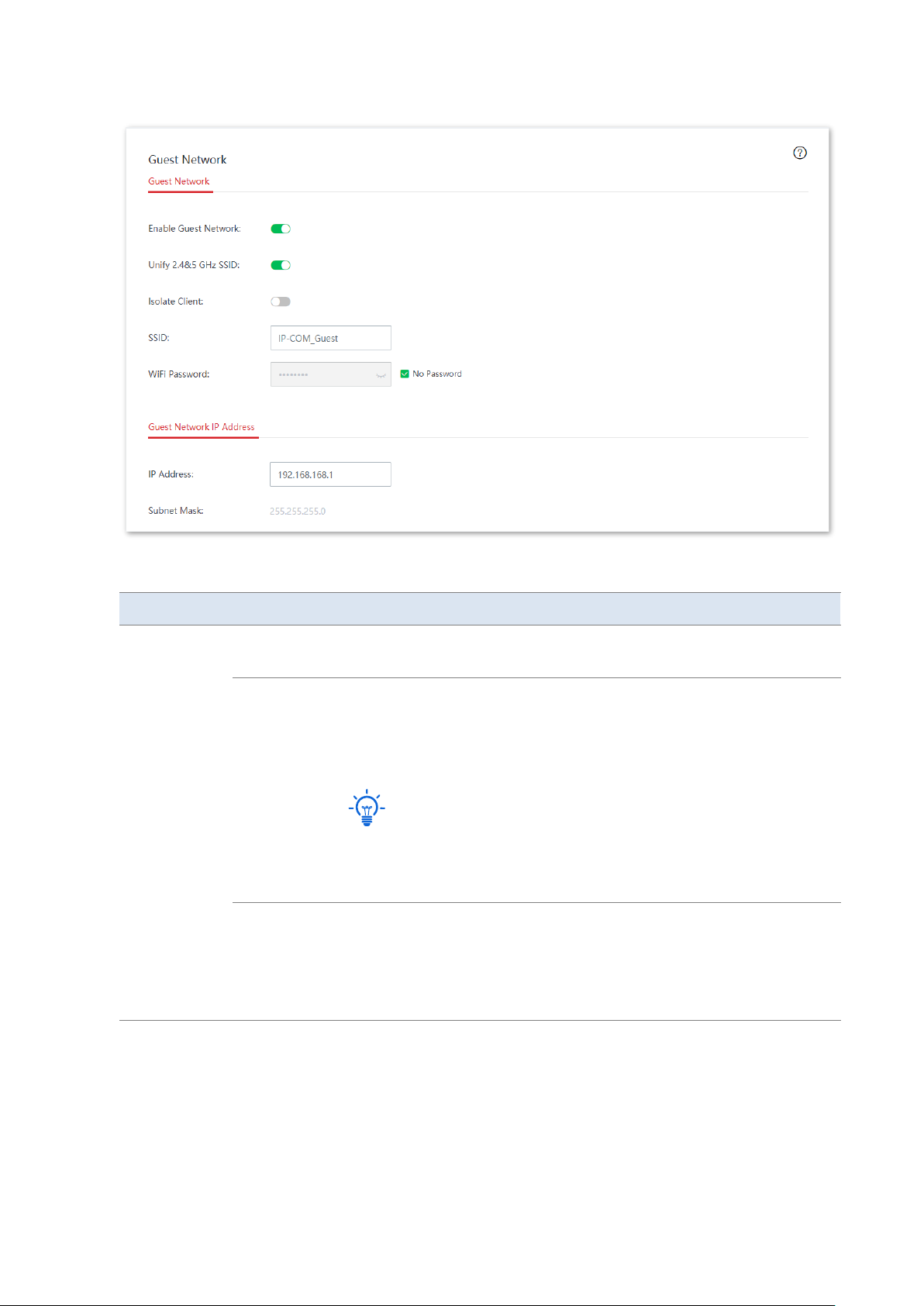
3.3.5 Guest network
On this page, you can configure the basic parameters of guest network, such as
enable/disable guest network, modify the SSID, and set the WiFi password.
Clients connected to the guest network can access only the internet and other wireless
clients connected to the guest network as well, and cannot access the web UI of the node or
the LAN where the primary network is deployed. The guest network meets the internet
requirement of guests and ensures the security of the primary network as well.
Click Wireless > Guest Network to enter the page. By default, this function is disabled. The
following displays the page when guest network is enabled.
Page 64
Version 1.0
57
Parameter description
Parameter
Description
Guest
Network
Enable Guest
Network
It is used to enable or disable the guest network function.
Unify 2.4&5
GHz SSID
After this function is enabled, the 2.4 GHz guest network and the 5 GHz
guest network share the same WiFi network name and password. A
wireless client will be automatically connected to the WiFi network with
the best network quality when connecting to the guest network.
Tip
If there are guest clients which support only the 2.4 GHz network in your
network, to avoid connection failure of these clients, you are
recommended not to enable this function.
Isolate Client
It specifies the isolation status of the wireless clients connected to the
guest network.
After this function is enabled, clients connected to the guest network
cannot communicate with each other, enhancing the security of the WiFi
network.
Page 65

Version 1.0
58
Parameter
Description
SSID
It specifies the WiFi network name of the guest network.
Tip
To help you identify the primary network, you are recommended to set a
different name for the guest network.
WiFi
Password
It specifies the WiFi password of the guest network.
No Password
It specifies that no password is set for the guest network. The
corresponding WiFi network is open.
Guest
Network IP
Address
IP Address
The default IP address of the guest network is 192.168.168.1. After
wireless clients connect to the guest network, they will obtain such an IP
address (192.168.168.X). Generally, you are recommended to retain the
default settings.
Subnet Mask
It specifies the subnet mask of the guest network, which is used to
define the address space of the guest network.
Page 66
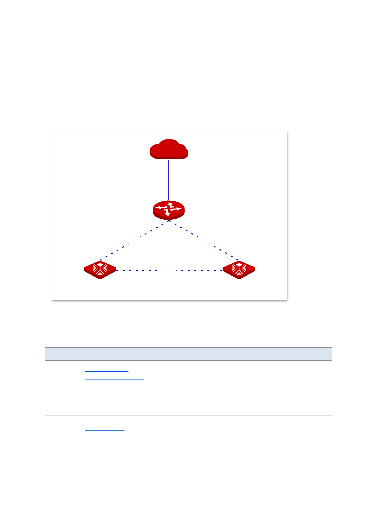
Version 1.0
59
3.4 Node management
3.4.1 Overview
The cable-free (router mode) node features the node management function which can
centrally manage other IP-COM cable-free devices in a network. See the following network
topology.
◼
Configuration wizard
After a cable-free device joins the cable-free network, it can be managed centrally. See the
following table for configuration procedures and tasks.
Procedure
Task
Description
1
Enable the node
management function
Optional.
This function is enabled by default.
2
Configure wireless policy
Required.
Configure the configuration information of the node in the
form of policy.
3
Maintain node
Required.
Deliver configurations to the node.
Mesh
Mesh
Mesh
Internet
Internet
Cable-free primary node:
Cable-free (router mode)
Cable-free secondary node
Cable-free secondary node
Page 67
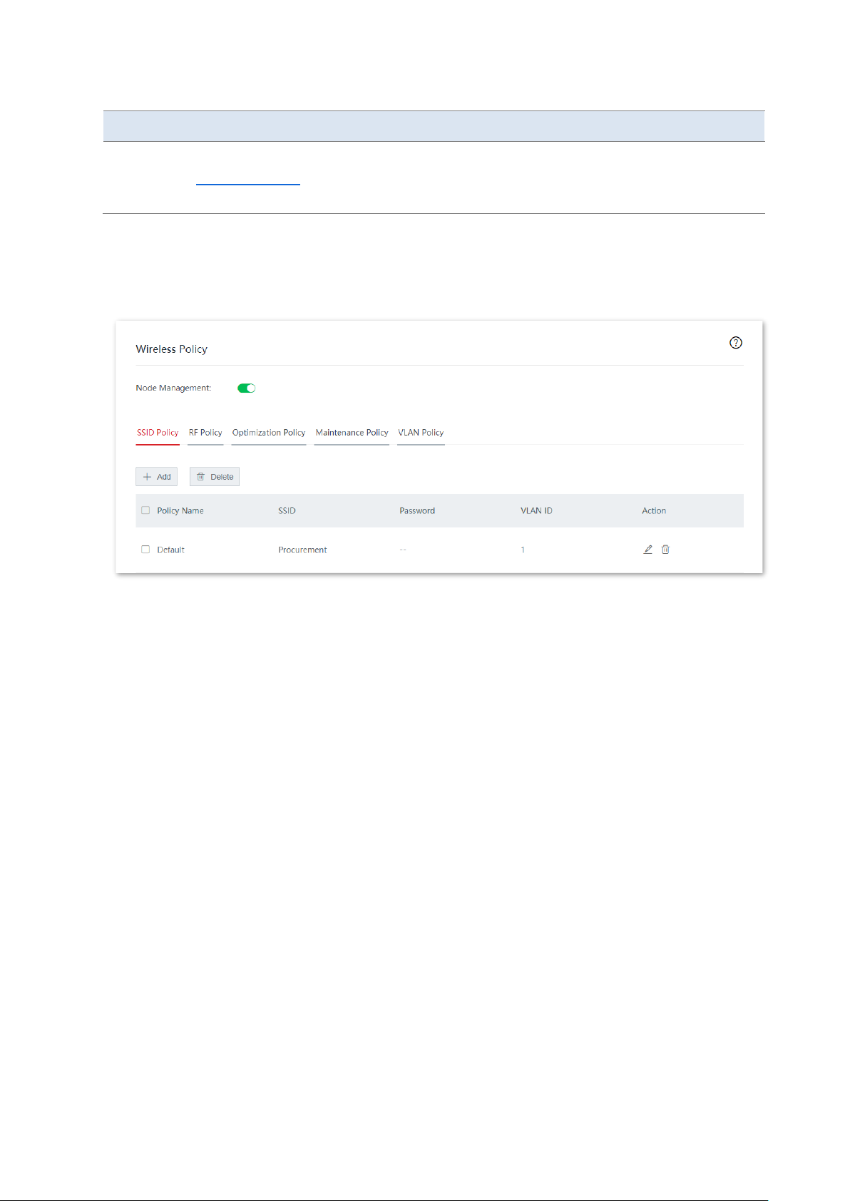
Version 1.0
60
Procedure
Task
Description
4
Topology routing
Optional.
View the current network topology, manually specify the
preferred transmission path between two nodes.
◼
Enable the node management function
The node management function is enabled by default. If you want to change its status, click
Node Management > Wireless Policy to enter the page.
3.4.2 Wireless policy
On this page, you can configure the configuration information of a node, such as SSID policy,
RF policy, optimization policy, maintenance policy, and VLAN policy. You can use these policies
in Wireless > Maintenance > Policy Delivery.
Click Node Management > Wireless Policy to enter the page.
SSID policy
SSID policy is used to configure the SSID-related parameters of the node.
Add a policy
On the Node Management > Wireless Policy > SSID Policy page, click + Add to enter the
configuration window.
Page 68
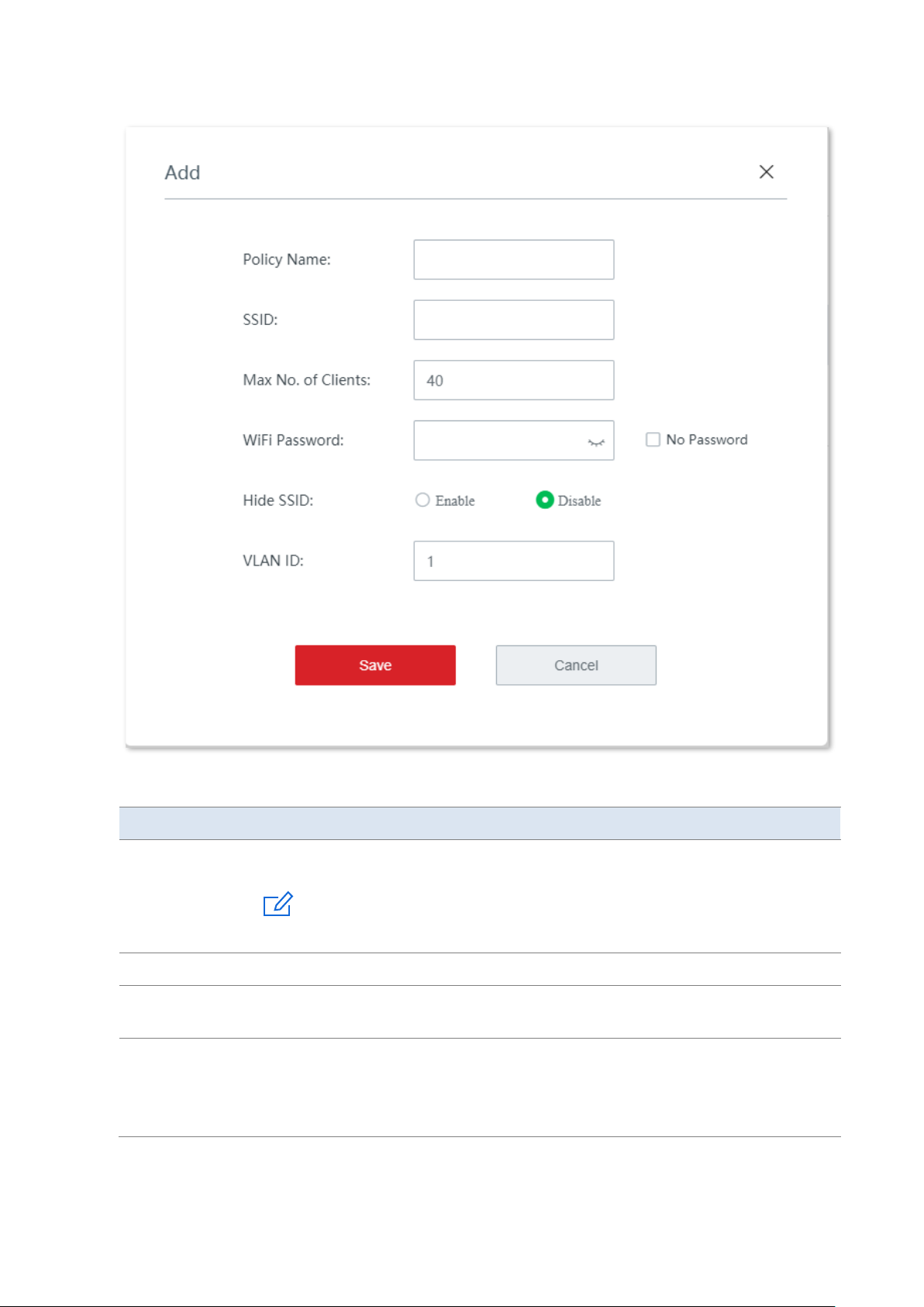
Version 1.0
61
Parameter description
Parameter
Description
Policy Name
It specifies the name of the SSID policy.
Note
The SSID policy name cannot be duplicated.
SSID
It specifies the name of the WiFi network.
Max No. of
Clients
It specifies the maximum number of clients allowed to connect to the WiFi network.
WiFi Password
It specifies the WPA-PSK or WPA2-PSK, which is also the WiFi password users need to
enter when connecting the WiFi network.
No Password: It specifies that no WiFi password is set for the WiFi network and the
WiFi network is open.
Page 69
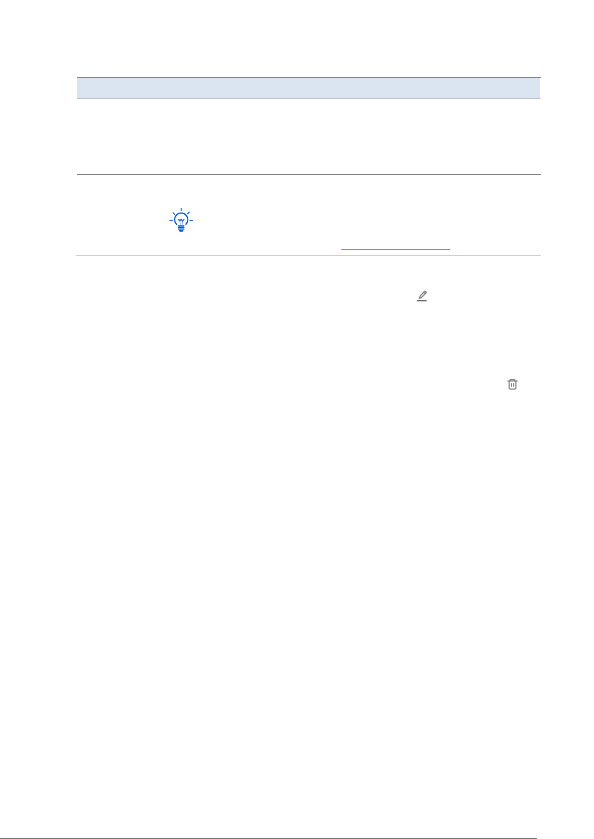
Version 1.0
62
Parameter
Description
Hide SSID
After this function is enabled, the SSID will be hidden and the WiFi network will not
appear in the available network list of wireless clients (such as smartphones),
enhancing the security of the WiFi network.
If you want to connect to the hidden WiFi network, manually enter the SSID on your
wireless clients.
VLAN ID
It specifies the VLAN to which the WiFi network belongs. The default VLAN ID is 1.
Tip
The VLAN ID takes effect only when you enable the VLAN function for the node.
Modify the policy
On the Node Management > Wireless Policy > SSID Policy page, click in the Action
column to modify the corresponding policy.
Delete the policy
You can delete a policy that has not been used (not been delivered to online nodes yet).
Delete one policy: On the Node Management > Wireless Policy > SSID Policy page, click in
the Action column of the corresponding policy.
Delete policies in batches: On the Node Management > Wireless Policy > SSID Policy page,
check the policies to be deleted and click Delete.
RF policy
RF policy is used to configure the basic RF parameters of the node.
Add a policy
On the Node Management > Wireless Policy > RF Policy page, click + Add to enter the
configuration window.
Page 70
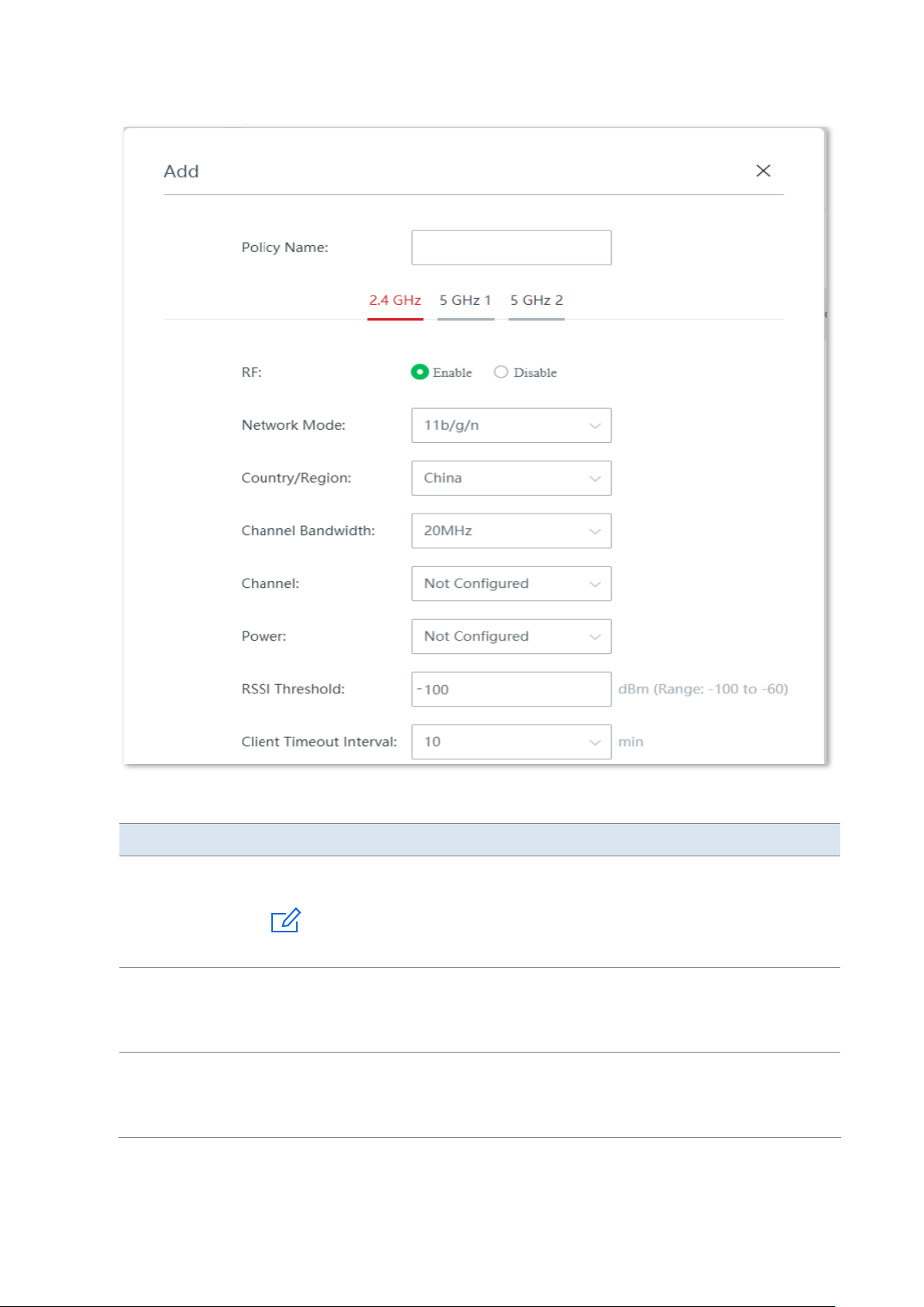
Version 1.0
63
Parameter description
Parameter
Description
Policy Name
It specifies the name of the RF policy.
Note
The RF policy name cannot be duplicated.
2.4 GHz
5 GHz 1
5 GHz 2
It is for you to choose the frequency band to be configured. If you only choose one
frequency band, the other two frequency bands retain the default settings.
RF
It specifies the status of the WiFi function.
−
Enable: Choose it to enable the WiFi function of the frequency band.
−
Disable: Choose it to disable the WiFi function of the frequency band.
Page 71

Version 1.0
64
Parameter
Description
Network Mode
It specifies the WiFi network mode of the corresponding band.
Network modes of the 2.4 GHz frequency band include 11b, 11g, 11b/g, 11b/g/n,
and n+256QAM.
−
11b: In this mode, only 802.11b wireless clients are allowed to access the 2.4
GHz WiFi network.
−
11g: In this mode, only 802.11g wireless clients are allowed to access the 2.4
GHz WiFi network.
−
11b/g: In this mode, 802.11b and 802.11g wireless clients can access the 2.4
GHz WiFi network.
−
11b/g/n: In this mode, wireless clients compliant with 802.11b or 802.11g
and wireless clients working at 2.4 GHz and compliant with 802.11n can
access the 2.4 GHz WiFi network.
−
n+256QAM: Wireless clients compliant with 802.11b or 802.11g and wireless
clients working at 2.4 GHz and compliant with 802.11n can access the 2.4 GHz
WiFi network.
QAM, abbreviated for Quadrature Amplitude Modulation, is a modulation
scheme that moderates amplitude on two orthogonal carriers. Using the
orthogonality of sine wave and cosine wave, it moderates two signals at the
same time, improving the modulation efficiency. In the n+256QAM network
mode, the 256-QAM modulation mode compliant with the IEEE 802.11ac
standard can be used under the IEEE 802.11n standard in the 2.4GHz band,
which improves the single stream rate from 150 Mbps to 200 Mbps.
Note: Such improvement can be realized only when the band is 2.4 GHz band,
and the transmitting an d receiving ends both support the n+256QAM
network mode. If any one end does not support n+256QAM, the single
stream rate under the 2.4 GHz band is still 150 Mbps at most. Moreover, after
the network mode is set to n+256QAM, the stability and anti-interference
capability of the network will be reduced compared with the stability and
anti-interference capability under other modes.
Network modes of the 5 GHz 1 frequency band and the 5 GHz 2 frequency band
include 11a, 11ac, and 11a/n.
−
11a: In this mode, only 802.11a wireless clients are allowed to access the 5
GHz WiFi network.
−
11ac: In this mode, only 802.11ac wireless clients are allowed to access the 5
GHz WiFi network.
−
11a/n: In this mode, wireless clients compliant with 802.11a and wireless
clients working at 5 GHz and compliant with 802.11n can access the 5 GHz
WiFi network.
Country/Region
It specifies the country or region where the node is located. Please select the correct
country or region.
Page 72

Version 1.0
65
Parameter
Description
Channel
Bandwidth
It specifies the bandwidth of the working channel. A high channel bandwidth means
a higher transmission rate, but the penetration capability is reduced and the
transmission distance is shortened.
−
20MHz: The node uses the 20MHz channel bandwidth.
−
40MHz: The node uses the 40MHz channel bandwidth.
−
20MHz/40MHz: This channel bandwidth is available only for the 2.4 GHz only.
The node automatically adjusts the channel bandwidth to 20MHz or 40MHz
based on the surrounding environment.
−
80MHz: This channel bandwidth is available only for the 5 GHz only. The node
uses the 80MHz channel bandwidth.
Channel
It specifies the channel in which the wireless data is transmitted and received. The
available channels are determined by the current country/region and wireless band.
−
Not Configured: Retain the current configurations of the node.
−
Auto: The node automatically detects the occupation rate of channels and
selects the appropriate working channel accordingly.
If connection drop, freeze or slow internet occurs frequently when you are using the
WiFi network, you can try changing the working channel. You can check the channels
with low occupation rate and little interference using software tools (such as WiFi
analyzer).
Power
It specifies the transmit power of the corresponding band.
The higher the transmit power, the wider the WiFi coverage. However, an
appropriate reduction of transmit power can help improve the performance and
security of the WiFi network.
Not Configured: Retain the current configurations of the node.
RSSI Threshold
It specifies the minimum wireless signal strength can be received by the band.
Clients with a lower signal strength value cannot connect to the node.
When there are multiple nodes in the surroundings, an appropriate RSSI value helps
ensure wireless clients connects to the nodes with a stronger signal.
Client Timeout
Interval
If a client generates no data communication within this interval after connecting to
the WiFi network, the node will cut this client off.
Show/Hide
Advanced Settings
Click to expand/collapse the advanced parameters: mandatory rate and optional
rate.
Mandatory Rate
By adjusting the mandatory rate and optional rate, you can limit access from lowspeed clients, thus improving the internet experience of other clients.
−
Mandatory Rate: It is a group of mandatory rates of the node. Clients must
support these mandatory rates; otherwise, the clients will fail to access the
WiFi network.
−
Optional Rate: It is a collection of other rates supported by the node except
for mandatory rates. These optional rates help clients realize connection with
the node at a higher rate.
Optional Rate
Page 73
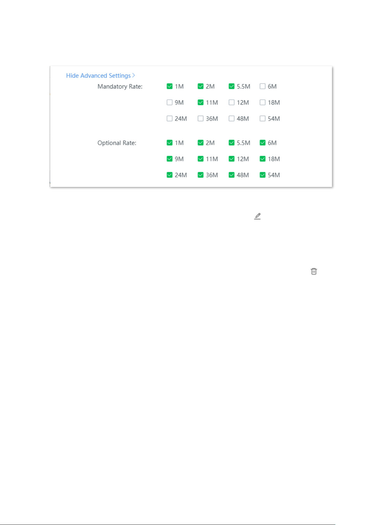
Version 1.0
66
Refer to the following figure for the advanced parameters.
Modify the policy
On the Node Management > Wireless Policy > RF Policy page, click in the Action column
to modify the corresponding policy.
Delete the policy
You can delete a policy that has not been used (not been delivered to online nodes yet).
Delete one policy: On the Node Management > Wireless Policy > RF Policy page, click in
the Action column of the corresponding policy.
Delete policies in batches: On the Node Management > Wireless Policy > RF Policy page,
check the policies to be deleted and click Delete.
Optimization policy
Optimization policy is used to configure the optimization parameters of the node.
Add a policy
On the Node Management > Wireless Policy > Optimization Policy page, click + Add to enter
the configuration window.
Page 74
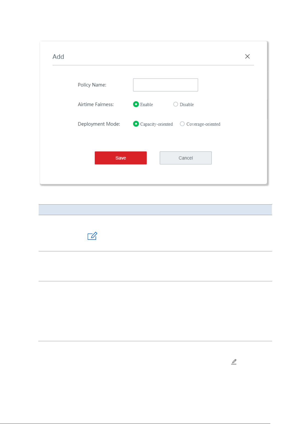
Version 1.0
67
Parameter description
Parameter
Description
Policy Name
It specifies the name of the optimization policy.
Note
The optimization policy name cannot be duplicated.
Airtime Fairness
After this function is enabled, the node fairly allocates download transmission time
to clients, which guarantees that high-speed clients and low-speed clients obtain the
same download transmission time. In this way, high-speed clients can transmit more
data, achieving higher system throughput and a larger number of accessed clients.
Deployment Mode
Choose a deployment mode based on the deployment intensity of nodes.
−
Capacity-oriented: This deployment mode is generally used in scenarios
where nodes are deployed intensively, such as meeting hall, exhibition hall,
banquet hall, gym, university classroom, and airport. This mode can
effectively reduce interferences between nodes.
−
Coverage-oriented: This deployment mode is generally used in scenarios
where nodes are deployed loosely, such as office, warehouse, and hospital.
This mode can expand the coverage of nodes.
Modify the policy
On the Node Management > Wireless Policy > Optimization Policy page, click in the
Action column to modify the corresponding policy.
Page 75

Version 1.0
68
Delete the policy
You can delete a policy that has not been used (not been delivered to online nodes yet).
Delete one policy: On the Node Management > Wireless Policy > Optimization Policy page,
click in the Action column of the corresponding policy.
Delete policies in batches: On the Node Management > Wireless Policy > Optimization Policy
page, check the policies to be deleted and click Delete.
Maintenance policy
Maintenance policy is used to configure the customized reboot parameters of the node. An
appropriate maintenance policy helps avoid such phenomena as deteriorating performance
and instability of the cable-free network caused by long time operation.
Tip
− Maintenance policies take effect for managed nodes and the time point when the maintenance policies
start being effective is counted based on the system time of the managed nodes. Please make sure that
the system time of the managed nodes is correct.
− During the reboot, all connections will be cut off; therefore, you are recommended to schedule the
maintenance time at an idle period to minimize its effect on your businesses.
Add a policy
On the Node Management > Wireless Policy > Maintenance Policy page, click + Add to enter
the configuration window.
Page 76
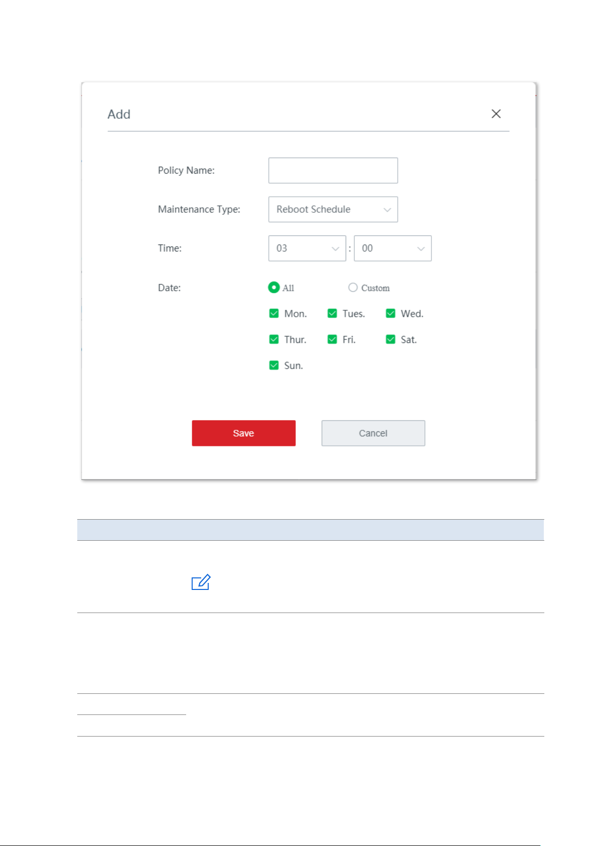
Version 1.0
69
Parameter description
Parameter
Description
Policy Name
It specifies the name of the maintenance policy.
Note
The maintenance policy name cannot be duplicated.
Maintenance Type
It specifies the maintenance type of the node. You can choose between reboot
schedule and cyclic reboot.
−
Reboot Schedule: The node reboots once at the specified time point on
the specified date(s).
−
Cyclic Reboot: The node reboots once every specified interval.
Time
If the Maintenance Type is set to Reboot Schedule, set these two parameters to
set the time point and dates when the node reboots.
Date
Page 77

Version 1.0
70
Parameter
Description
Interval
If the Maintenance Type is set to Cyclic Reboot, set this parameter to set the
reboot interval.
Modify the policy
On the Node Management > Wireless Policy > Maintenance Policy page, click in the
Action column to modify the corresponding policy.
Delete the policy
You can delete a policy that has not been used (not been delivered to online nodes yet).
Delete one policy: On the Node Management > Wireless Policy > Maintenance Policy page,
click in the Action column of the corresponding policy.
Delete policies in batches: On the Node Management > Wireless Policy > Maintenance
Policy page, check the policies to be deleted and click Delete.
VLAN policy
VLAN policy is used to configure the VLAN-related parameters of the node.
Tip
If you need to view the default values for each parameter in VLAN policy, refer to the default settings for
each parameter when a new VLAN policy is being added.
Add a policy
On the Node Management > Wireless Policy > VLAN Policy page, click + Add to enter the
configuration window.
Page 78
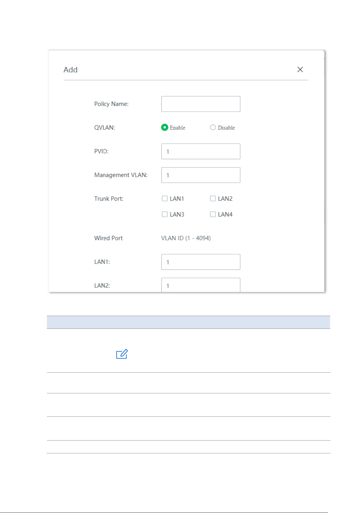
Version 1.0
71
Parameter description
Parameter
Description
Policy Name
It specifies the name of the VLAN policy.
Note
The VLAN policy name cannot be duplicated.
QVLAN
It specifies whether to enable the QVLAN function. By default, this function is
enabled.
PVID
It specifies the ID of the default native VLAN of the trunk port of the node. After
the QVLAN function is enabled, the LAN port is the trunk port. Traffic of all VLANs
can pass through a trunk port. Its default value is 1.
Management VLAN
It specifies the ID of the management VLAN. The default value is 1.
After changing the management VLAN, you can manage the node only after
connecting your computer to the new management VLAN.
Trunk Port
Select the trunk port(s). The trunk port allows data of all VLANs to pass.
Page 79
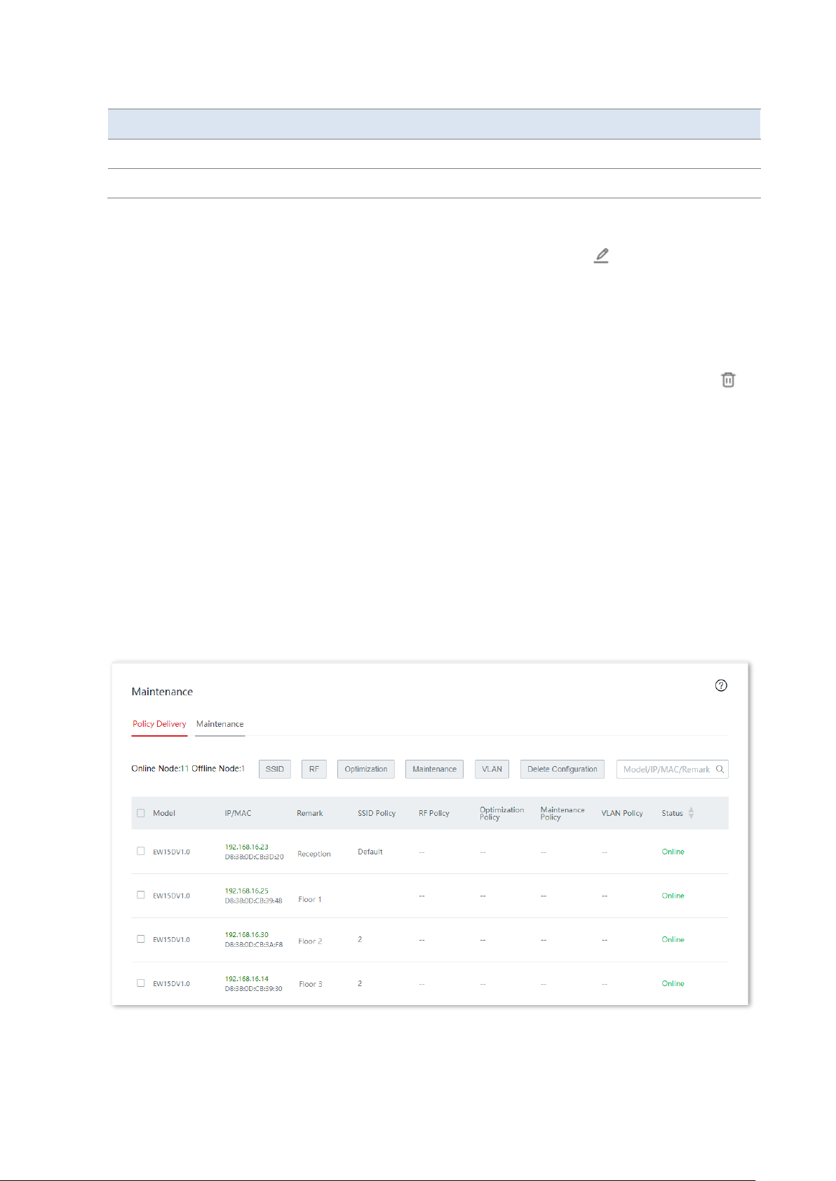
Version 1.0
72
Parameter
Description
Wired Port
It specifies the wired LAN port of the node.
VLAN ID
It specifies the VLAN ID of the port. The default value is 1.
Modify the policy
On the Node Management > Wireless Policy > VLAN Policy page, click in the Action
column to modify the corresponding policy.
Delete the policy
You can delete a policy that has not been used (not been delivered to online nodes yet).
Delete one policy: On the Node Management > Wireless Policy > VLAN Policy page, click
in the Action column of the corresponding policy.
Delete policies in batches: On the Node Management > Wireless Policy > VLAN Policy page,
check the policies to be deleted and click Delete.
3.4.3 Maintenance
On this page, you can deliver the wireless policies you configured to online nodes, delete the
configurations of nodes, reboot/reset online nodes in batches, delete offline nodes in batches,
modify the configuration of a node separately, and check/export the information of managed
nodes.
Click Node Management > Maintenance to enter the page.
Page 80
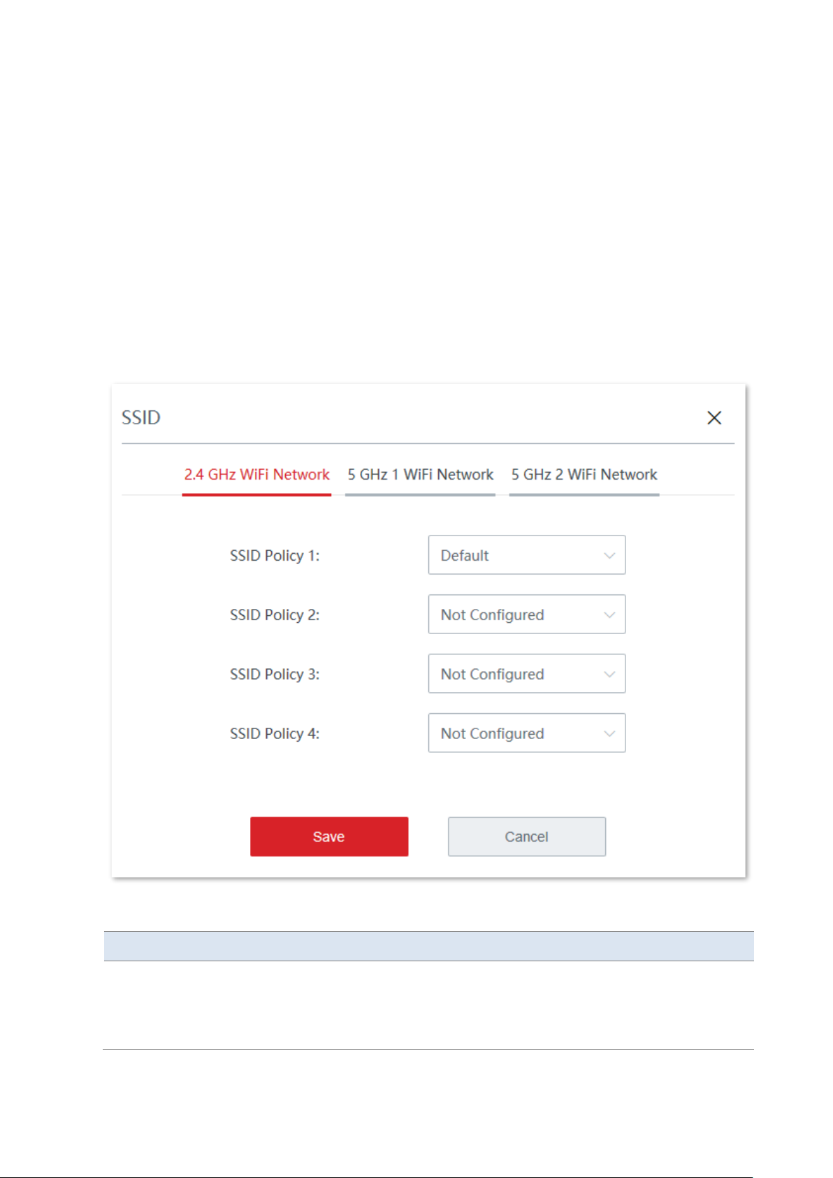
Version 1.0
73
Policy delivery
Policy delivery is used to deliver configured policies to online nodes.
SSID
Click SSID to deliver SSID policies to one or multiple online nodes.
Deliver SSID policies:
1. On the Node Management > Maintenance > Policy Delivery page, select the nodes to which
you deliver SSID policies.
2. Click SSID and configure the parameters.
3. Click Save.
Parameter description
Parameter
Description
2.4 GHz WiFi Network
5 GHz 1 WiFi Network
5 GHz 2 WiFi Network
Select the wireless frequency band on which the SSID policy takes effect.
Available SSID bands depend on the secondary node. If the secondary node does
not support 5 GHz, 5GHz settings won’t be allowed.
−
If both 2.4 GHz and 5 GHz bands are needed at the same time, please
Page 81
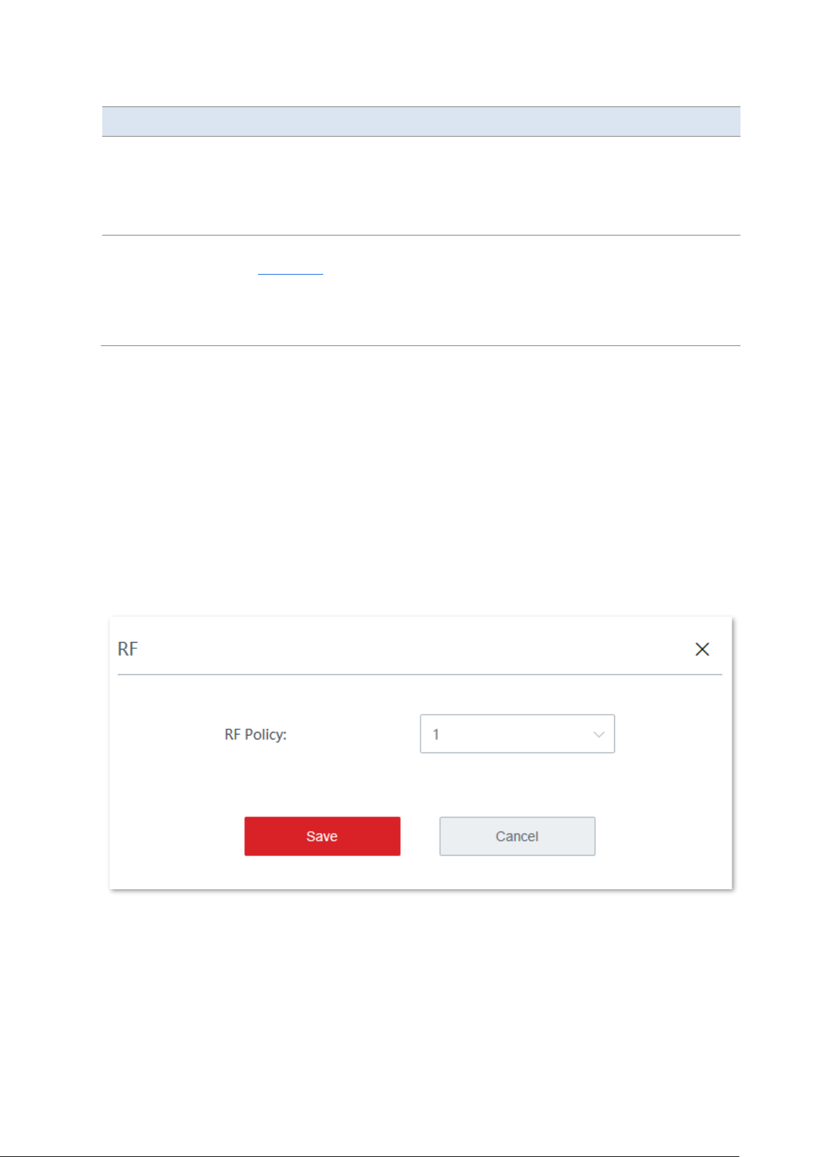
Version 1.0
74
Parameter
Description
configure them one after the other, and then click Save.
−
If some selected secondary nodes only support 2.4 GHz, and some
selected secondary nodes support both 2.4 GHz and 5 GHz, the AC will
automatically issue wireless settings to secondary nodes according to
their actual supported wireless bands.
SSID Policy 1/2/3/4
Select the SSID policy to be delivered. SSID policies must be configured in the
SSID policy module in advance.
If the node enables multiple wireless networks, each network must be
configured with a unique SSID policy.
Not Configured: Current configuration of the node remains unchanged.
----End
The SSID policies will be delivered to the selected nodes.
RF
Click RF to deliver RF policies to one or multiple online nodes.
Deliver an RF policy:
1. On the Node Management > Maintenance > Policy Delivery page, select the nodes to which
you deliver an RF policy.
2. Click RF and select the target RF policy.
3. Click Save.
Page 82
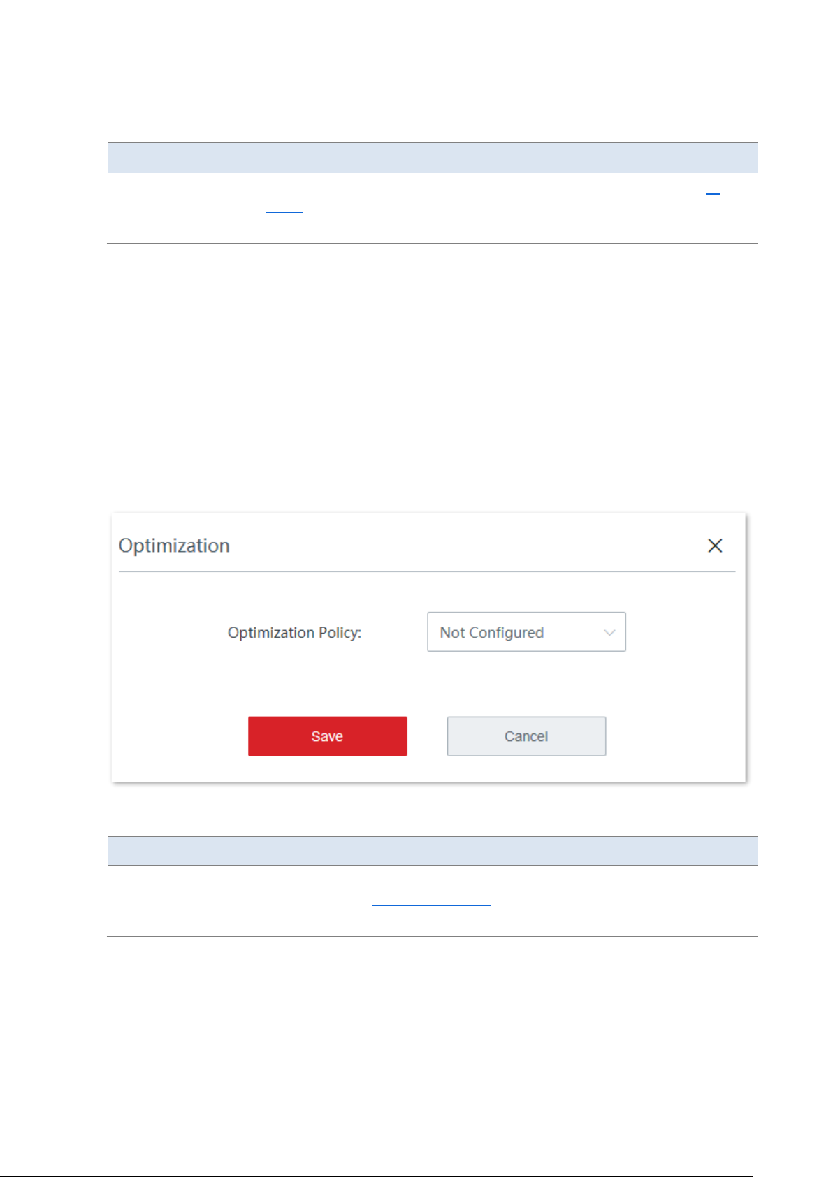
Version 1.0
75
Parameter description
Parameter
Description
RF Policy
Select the RF policy to be delivered. RF policies must be configured in the RF
policy module in advance.
Not Configured: Current configuration of the node remains unchanged.
----End
The RF policy will be delivered to the selected nodes.
Optimization
Click Optimization to deliver optimization policies to one or multiple online nodes.
Deliver an optimization policy:
1. On the Node Management > Maintenance > Policy Delivery page, select the nodes to which
you deliver an optimization policy.
2. Click Optimization and select the target optimization policy.
3. Click Save.
Parameter description
Parameter
Description
Optimization Policy
Select the optimization policy to be delivered. Optimization policies must be
configured in the Optimization policy module in advance.
Not Configured: Current configuration of the node remains unchanged.
----End
The optimization policy will be delivered to the selected nodes.
Page 83
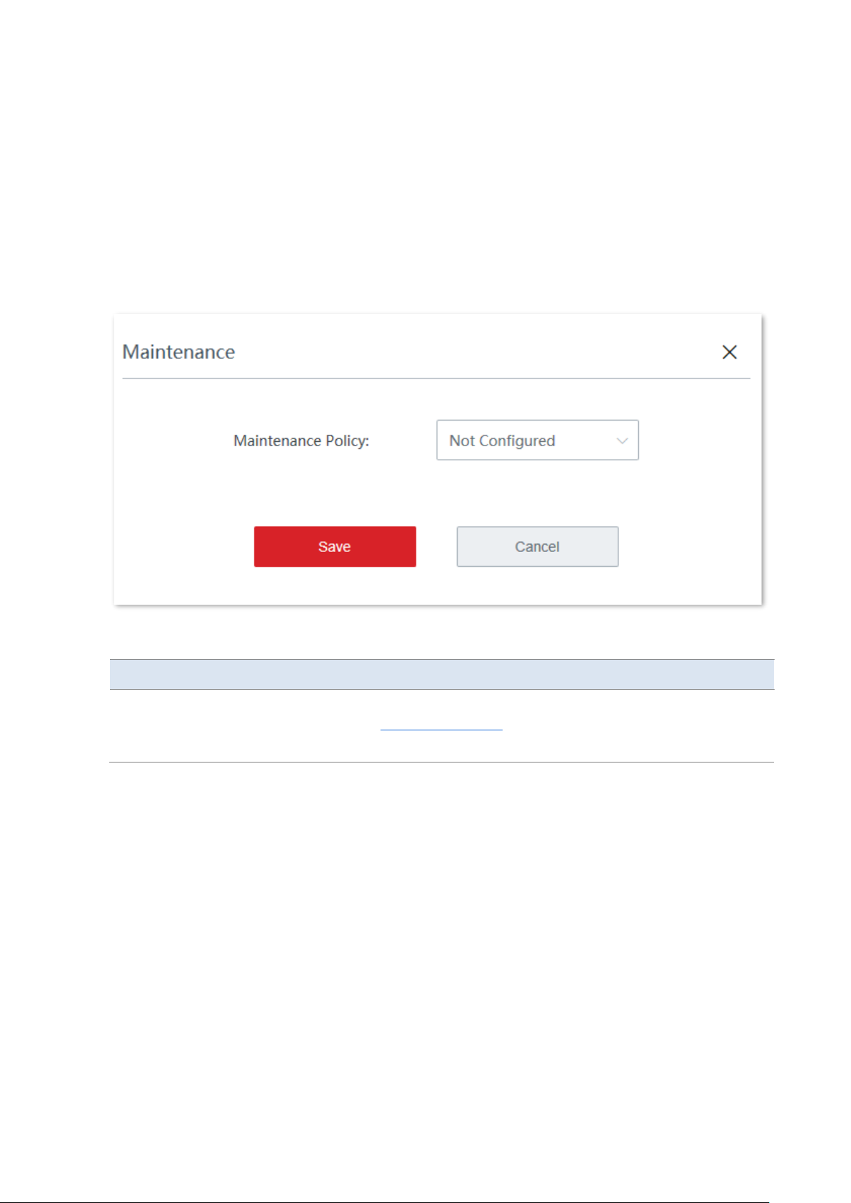
Version 1.0
76
Maintenance
Click Maintenance to deliver maintenance policies to one or multiple online nodes.
Deliver a maintenance policy:
1. On the Node Management > Maintenance > Policy Delivery page, select the nodes to which
you deliver a maintenance policy.
2. Click Maintenance and select the target maintenance policy.
3. Click Save.
Parameter description
Parameter
Description
Maintenance Policy
Select the maintenance policy to be delivered. Maintenance policies must be
configured in the Maintenance policy module in advance.
Not Configured: Current configuration of the node remains unchanged.
----End
The maintenance policy will be delivered to the selected nodes.
VLAN
Click VLAN to deliver VLAN policies to one or multiple online nodes.
Deliver a VLAN policy:
1. On the Node Management > Maintenance > Policy Delivery page, select the nodes to which
you deliver a VLAN policy.
2. Click VLAN and select the target VLAN policy.
3. Click Save.
Page 84
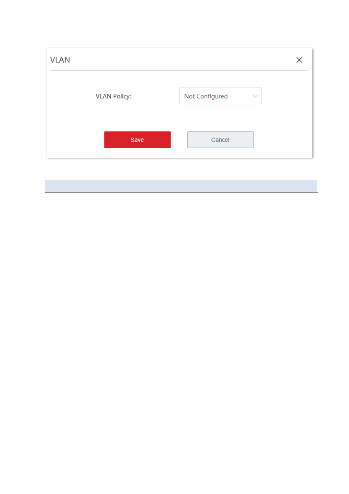
Version 1.0
77
Parameter description
Parameter
Description
VLAN Policy
Select the VLAN policy to be delivered. VLAN policies must be configured in the
VLAN policy module in advance.
Not Configured: Current configuration of the node remains unchanged.
----End
The VLAN policy will be delivered to the selected nodes.
Delete configuration
Click Delete Configuration to delete the configurations delivered to one or multiple online
nodes.
Delete configurations of one node: On the Node Management > Maintenance > Policy
Delivery page, check the target node and click Delete Configuration.
Delete configurations in batches: On the Node Management > Maintenance > Policy
Delivery page, check the nodes whose configurations you want to delete and click Delete
Configuration.
After you click Delete Configuration, all the policy configuration of the target node will be
restored to factory settings.
Maintenance
Click Node Management > Maintenance > Maintenance to enter the page.
Maintenance is used to reboot or reset online nodes in batches, check or export the
information of managed nodes, delete the information of offline nodes, and refresh the
displayed node information.
Page 85

Version 1.0
78
Reboot
Click Reboot to reboot one or multiple nodes.
Reboot node:
1. On the Node Management > Maintenance > Maintenance page, select the nodes to be
rebooted.
2. Click Reboot and follow the on-screen instructions.
----End
After the nodes are rebooted, they are offline for a while and then automatically get online
after the reboot completes. This whole process may take 1 to 2 minutes. Please wait with
patience. You can click Refresh on the same page to check the latest status of the node.
Reset
Click Reset to restore one or multiple nodes to factory settings.
Reset node:
1. On the Node Management > Maintenance > Maintenance page, select the nodes to be reset.
2. Click Reset and follow the on-screen instructions.
----End
Export
Click Export to export the node information in the Excel form and save it to the management
computer.
On the Node Management > Maintenance > Maintenance page, click Export and follow the
on-screen instructions.
Delete
Click Delete to delete the information of one or multiple offline nodes.
Delete one node: On the Node Management > Maintenance > Maintenance page, click on
the row where the target node resides.
Delete nodes in batches: On the Node Management > Maintenance > Maintenance page,
check the nodes to be deleted and click Delete.
Refresh
Click Refresh on the Node Management > Maintenance > Maintenance page to refresh the
displayed node information.
Page 86
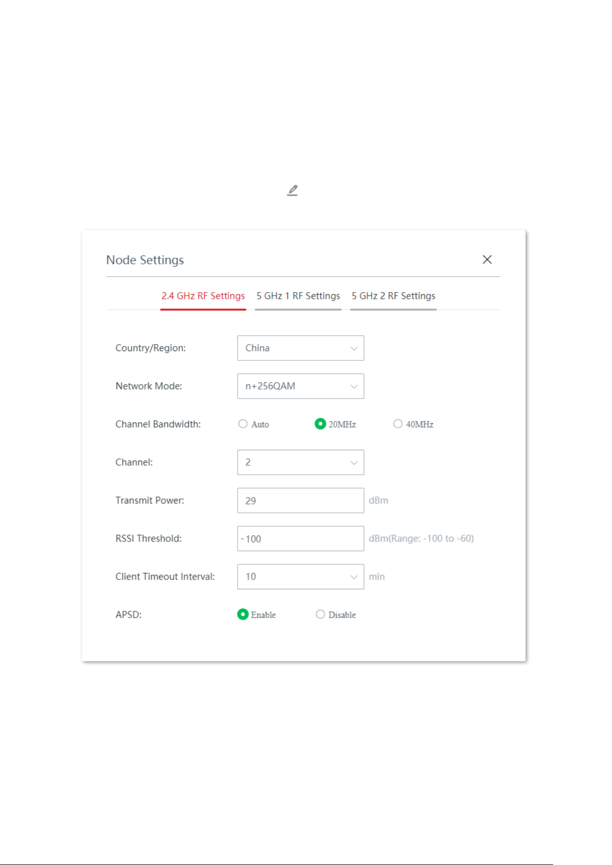
Version 1.0
79
Edit
Click Edit to edit separately the configurations of a node, such as its country/region, channel,
transmit power and other parameters.
Edit the configurations of a node:
1. On the Node Management > Maintenance > Maintenance page, locate the node whose
configurations you want to edit, and click on the row where the node resides.
2. Modify the parameters as required.
3. Click Save.
----End
The new configurations are automatically delivered to the target node.
Page 87

Version 1.0
80
Parameter description
Parameter
Description
Country/Region
It specifies the country or region where the node locates. Please select the
correct country/region to comply with the regulations of different countries or
regions have on channel or transmit power.
Network Mode
It specifies the WiFi network mode of the corresponding band.
Network modes of the 2.4 GHz WiFi network include 11b, 11g, 11b/g, 11b/g/n,
and n+256QAM. By default, the router works in the n+256QAM mode.
−
11b: In this mode, only 802.11b wireless clients are allowed to access the
2.4 GHz WiFi network.
−
11g: In this mode, only 802.11g wireless clients are allowed to access the
2.4 GHz WiFi network.
−
11b/g: In this mode, 802.11b and 802.11g wireless clients can access the
2.4 GHz WiFi network.
−
11b/g/n: In this mode, wireless clients compliant with 802.11b or 802.11g
and wireless clients working at 2.4 GHz and compliant with 802.11n can
access the 2.4 GHz WiFi network.
−
n+256QAM: Wireless clients compliant with 802.11b or 802.11g and
wireless clients working at 2.4 GHz and compliant with 802.11n can access
the 2.4 GHz WiFi network.
QAM, abbreviated for Quadrature Amplitude Modulation, is a modulation
scheme that moderates amplitude on two orthogonal carriers. Using the
orthogonality of sine wave and cosine wave, it moderates two signals at
the same time, improving the modulation efficiency. In the n+256QAM
network mode, the 256-QAM modulation mode compliant with the IEEE
802.11ac standard can be used under the IEEE 802.11n standard in the
2.4GHz band, which improves the single stream rate from 150 Mbps to
200 Mbps.
Note: Such improvement can be realized only when the band is 2.4 GHz
band, and the transmitting an d receiving ends both support the
n+256QAM network mode. If any one end does not support n+256QAM,
the single stream rate under the 2.4 GHz band is still 150 Mbps at most.
Moreover, after the network mode is set to n+256QAM, the stability and
anti-interference capability of the network will be reduced compared with
the stability and anti-interference capability under other modes.
Network modes of the 5 GHz WiFi network include 11a, 11ac, and 11a/n. By
default, the router works in the 11ac mode.
−
11a: In this mode, only 802.11a wireless clients are allowed to access the
5 GHz WiFi network.
−
11ac: In this mode, only 802.11ac wireless clients are allowed to access
the 5 GHz WiFi network.
−
11a/n: In this mode, wireless clients compliant with 802.11a and wireless
clients working at 5 GHz and compliant with 802.11n can access the 5 GHz
WiFi network.
Page 88

Version 1.0
81
Parameter
Description
Channel Bandwidth
It specifies the bandwidth of the working channel. A high channel bandwidth
means a higher transmission rate, but the penetration capability is reduced and
the transmission distance is shortened.
−
20MHz: The node uses the 20MHz channel bandwidth.
−
40MHz: The node uses the 40MHz channel bandwidth.
−
Auto: This channel bandwidth is available only for the 2.4 GHz only. The
node automatically adjusts the channel bandwidth to 20MHz or 40MHz
based on the surrounding environment.
−
80MHz: This channel bandwidth is available only for the 5 GHz only. The
node uses the 80MHz channel bandwidth.
Channel
It specifies the channel in which the wireless data is transmitted and received.
The available channels are determined by the current country/region and
wireless band.
Auto: The node automatically detects the occupation rate of channels and
selects the appropriate working channel accordingly.
If connection drop, freeze or slow internet occurs frequently when you are using
the WiFi network, you can try changing the working channel. You can check the
channels with low occupation rate and little interference using software tools
(such as WiFi analyzer).
Transmit Power
It specifies the transmit power of the corresponding band.
The higher the transmit power, the wider the WiFi coverage. However, an
appropriate reduction of transmit power can help improve the performance and
security of the WiFi network.
RSSI Threshold
It specifies the minimum wireless signal strength can be received by the band.
Clients with a lower signal strength value cannot connect to the node.
When there are multiple nodes in the surroundings, an appropriate RSSI value
helps ensure wireless clients connects to the nodes with a stronger signal.
Client Timeout
Interval
If a client generates no data communication within this interval after connecting
to the WiFi network, the node will cut this client off.
APSD
It is abbreviated for Automatic Power Save Delivery, which is the WMM powersaving certification protocol of the WiFi Alliance. Enabling APSD can reduce the
power consumption of the node.
3.4.4 Topology routing
On this page, you can check the network topology routes currently available and manually set
preferred routes between nodes. In the Network Topology module, you can check the
current topology, the status of the route, and select the nodes whose topology routes you
want to check. In the Communication Routing module, you can customize the preferred
route between two nodes.
Click Node Management > Topology Routing to enter the page.
Page 89
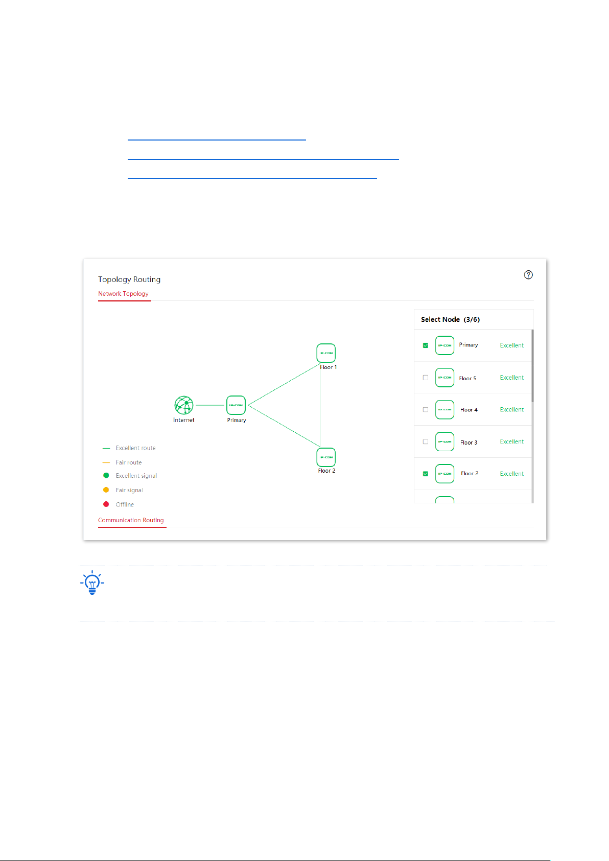
Version 1.0
82
Network topology
Click Node Management > Topology Routing to enter the page. In this module, you can:
− check the current network topology.
− check the connection status of the link between nodes.
− check the internet connection status of each node.
Check the current network topology
You can select the secondary nodes you want to display in the topology in the right column
and check the current network topology of the selected node. See the following figure.
Tip
At most 6 nodes can be displayed. You can select 6 or fewer than 6 nodes to check their network topology.
Check the connection status of the link between nodes
You can learn the link quality between two nodes according to the line color in the network
topology.
− —— indicates that the quality of the link between two nodes is excellent.
− —— indicates that the quality of the link between two nodes is fair.
Page 90
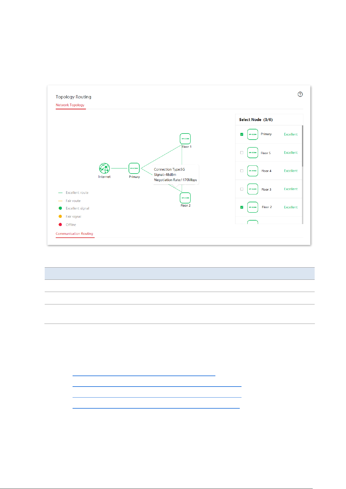
Version 1.0
83
Check the internet connection status of each node
You can view the internet connection status of each node by hovering the mouse to the node
icon in the network topology.
Parameter description
Parameter
Description
Connection Type
It specifies the way by which the node connects with the upstream node.
Signal
It specifies the strength of the signal this node received from the upstream node.
Negotiation Rate
It specifies the wireless negotiation rate between this node and the upstream
node.
Communication routing
Click Node Management > Topology Routing to enter the page. In this module, you can:
− add the preferred transmission path for two nodes.
− display the preferred transmission path between two nodes.
− modify the preferred transmission path between two nodes.
− delete the preferred transmission path between two nodes.
Page 91
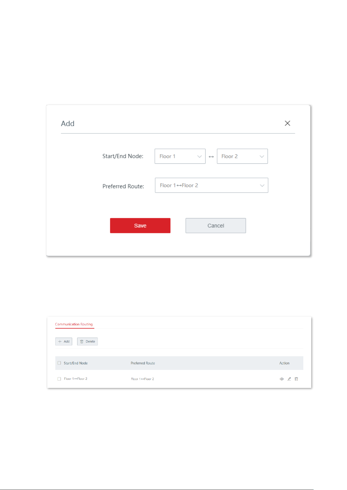
Version 1.0
84
Add the preferred transmission path for two nodes
You can manually specify the preferred transmission path between two nodes.
1. In the Communication Routing module on the Node Management > Topology Routing page,
click + Add.
2. When the configuration completes, click Save.
----End
After the rule of the preferred transmission path is added successfully, you can check the
added rule on the Node Management > Topology Routing > Communication Routing page.
See the following figure.
Page 92
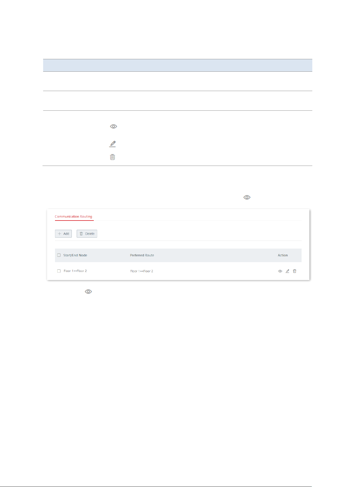
Version 1.0
85
Parameter description
Parameter
Description
Start/End Node
Click the drop-down list to select the start and end node. The start node and end
node cannot be the same.
Preferred Route
Click the drop-down list to select the preferred transmission path between the
two nodes.
Action
It specifies the operations you can perform on the rule.
: Click it to display the preferred transmission path between two nodes in
the network topology.
: Click it to edit the rule.
: Click it to delete the rule.
Display the preferred transmission path between two nodes
In the Communication Routing module on the Node Management > Topology Routing page,
locate the rules you want to display in the network topology and click .
After clicking , you can see the preferred transmission path between two nodes in the
network topology.
Page 93
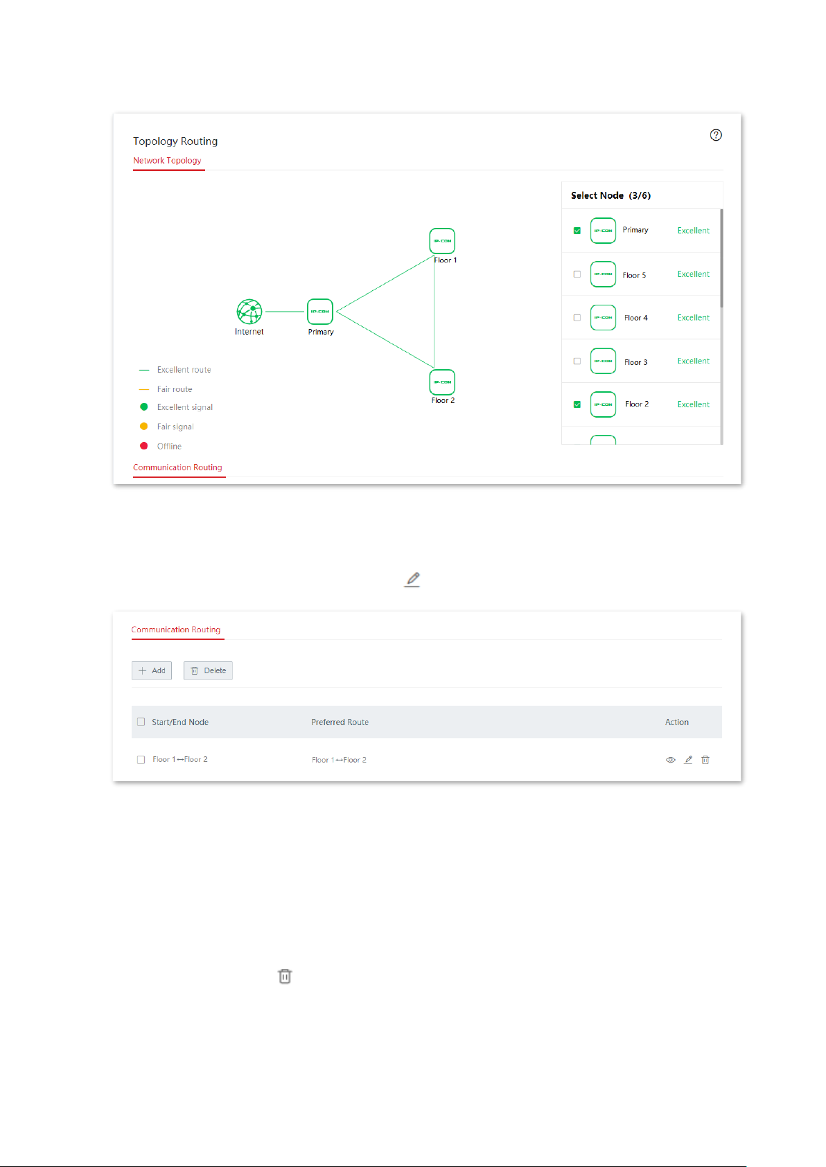
Version 1.0
86
Modify the preferred transmission path between two nodes
1. In the Communication Routing module on the Node Management > Topology Routing page,
locate the rule you want to modify and click .
2. Modify the rule and click Save.
----End
After the modification is saved, the new preferred transmission path rule is generated between
the two nodes.
Delete the preferred transmission path between two nodes
Delete one path: In the Communication Routing module on the Node Management >
Maintenance page, click on the row where the target path resides.
Delete paths in batches: In the Communication Routing module on the Node Management >
Maintenance page, select the paths to be deleted and click Delete.
Page 94
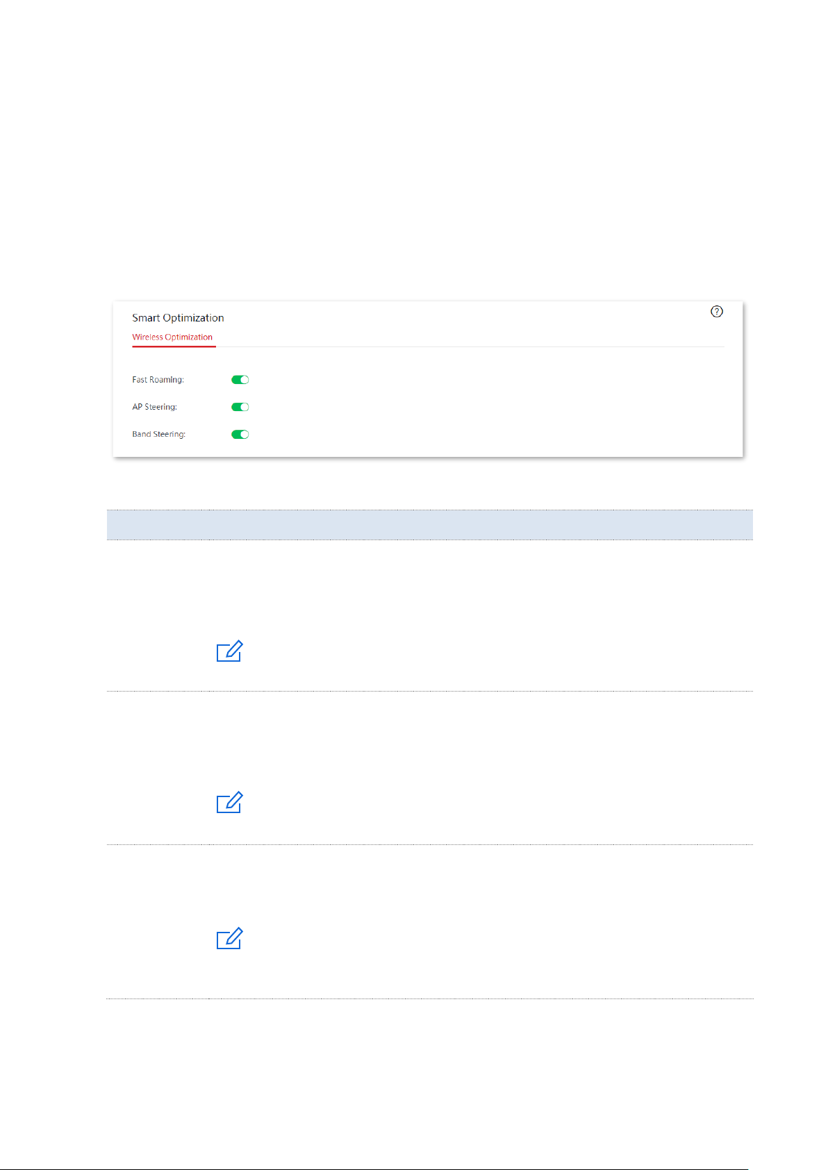
Version 1.0
87
3.5 Smart optimization
On this page, you can optimize the whole cable-free system network to enhance the user
experience.
Click Smart Optimization to enter the page.
On this page, you can control the enabling status of fast roaming, AP steering and band
steering to optimize the WiFi experience of the cable-free system.
Parameter description
Parameter
Description
Fast Roaming
After this function is enabled, clients with 802.11r capabilities are automatically switched
to other nodes if the WiFi signal they received from the current node decreases to the
threshold value for triggering fast roaming. This process takes only milliseconds. Enabling
this function to minimize the effects on services when users are moving across nodes.
Note
This function requires that all nodes share the same SSID and WiFi password.
AP Steering
After this function is enabled, clients with 802.11k and 802.11v capabilities can obtain
the network information of all the nodes and decide whether to switch to other nodes
with better network quality accordingly. Enabling this function to disperse clients and
ensure that clients connect to more appropriate nodes.
Note
This function requires that all nodes share the same SSID and WiFi password.
Band Steering
After this function is enabled, the node will guide dual-band clients to connect to the
frequency band with the better network quality based on the network quality of all
frequency bands.
Note
This function requires that the 2.4 GHz frequency band and the 5 GHz frequency band of
the node share the same SSID and WiFi password.
Page 95
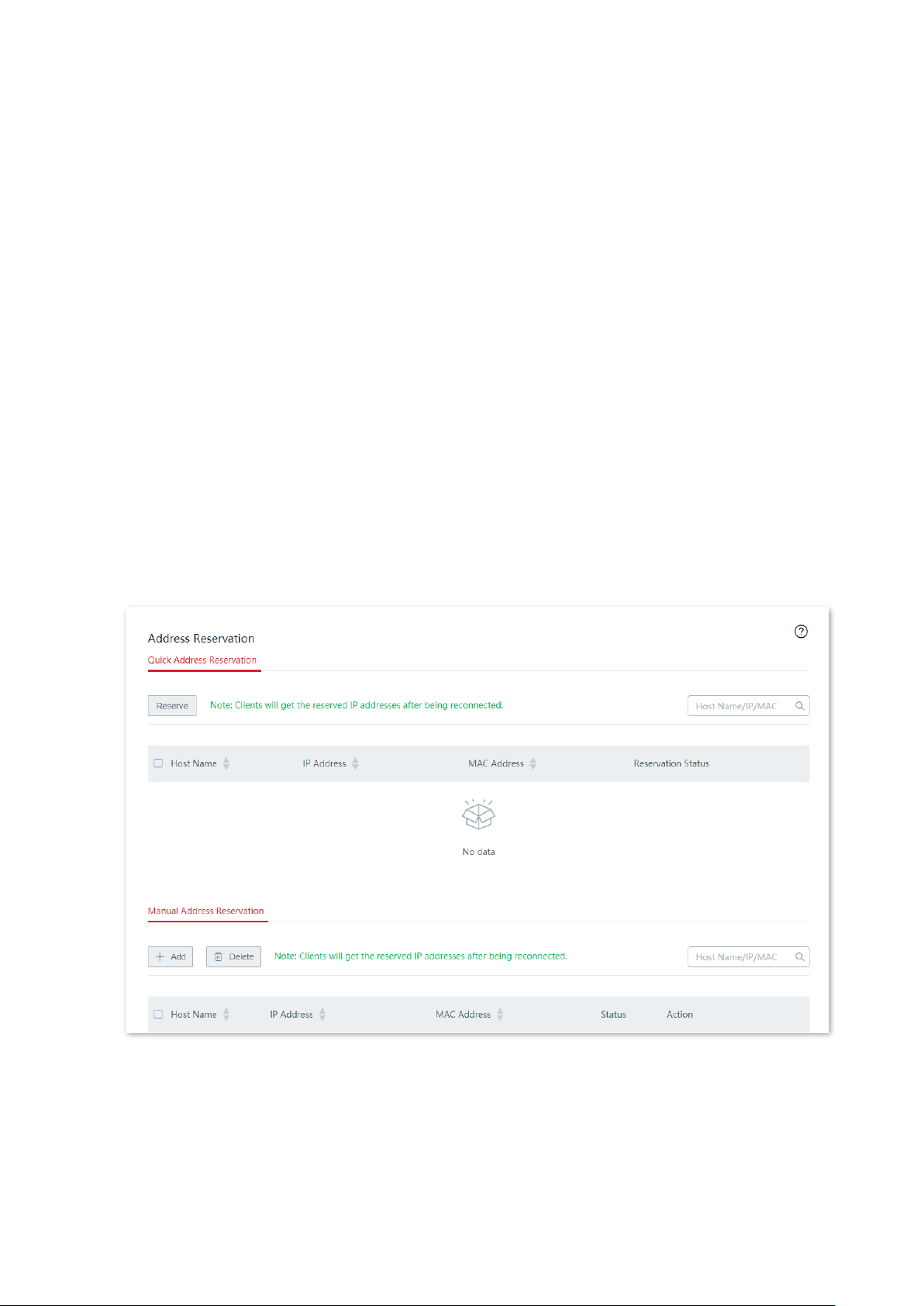
Version 1.0
88
3.6 Address reservation
3.6.1 Overview
On this page, you can specify a pre-set IP address for the specified client and make the client
obtain this IP address all the time. In this way, such functions depending on IP address as
filter management, bandwidth control, and port forwarding will not be ineffective because of
IP address change.
This function only takes effect when the DHCP server function of the node is enabled. The
node supports the following two address reservation methods:
− Quick Address Reservation: You can check the information of the clients obtaining IP
address from the DHCP server of the node, and reserve IP address for clients by just
clicking Reserve. In this way, the DHCP server will assign the fixed IP address for the
fixed client all the time.
− Manual Address Reservation: You can manually reserve address for client to let the
DHCP server assign fixed IP address for fixed client all the time.
Click Address Reservation to enter the page. See the following figure.
Page 96

Version 1.0
89
Parameter description
Parameter
Description
Quick
Address
Reservation
Reserve
It is used to bind the IP address of the selected node with the MAC
address of the selected node.
Host Name
It specifies the name of the client.
IP Address
It specifies the IP address of the client.
MAC Address
It specifies the MAC address of the client.
Reservation Status
Click Reserve to bind the IP address and MAC address together, so
the client will obtain the reserved IP address all the time. If the
reservation is successful, the reservation status will be displayed as
Reserved.
Manual
Address
Reservation
Host Name
It specifies the name of the client or remarks of static IP address
reservation rule.
IP Address
It specifies the IP address reserved for the client with the target MAC
address.
MAC Address
It specifies the MAC address of the client.
Status
It specifies the status of the rule. You can enable or disable the rule
as required.
Action
It specifies the operations you can perform on the rule.
: Click it to edit the rule.
: Click it to delete the rule.
Export Configuration
Click Export to back up the static IP reservation table to the local
computer.
Import Configuration
It is used to import the backed up static IP reservation table to the
node.
3.6.2 Configure address reservation
If you want to assign IP address for clients already connecting to the cable-free network, it is
recommended that you configure on the Quick Address Reservation module. Otherwise,
configure on the Manual Address Reservation module.
Quick address reservation
Reserve IP address for one client:
On the Address Reservation > Quick Address Reservation page, locate the client to which
you assign a fixed IP address and click Reserve.
Page 97
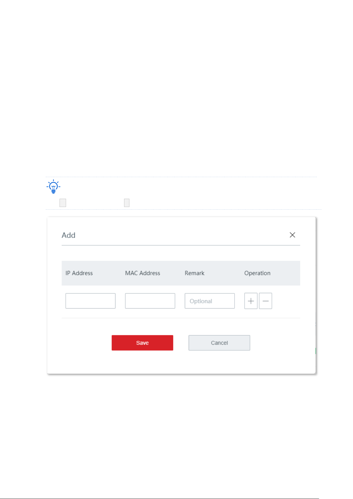
Version 1.0
90
Reserve IP addresses for multiple clients:
On the Address Reservation > Manual Address Reservation page, select the clients to which
you assign fixed IP addresses and click Reserve.
After IP address is reserved successfully, you can check the added rules on the Address
Reservation > Manual Address Reservation page. The rules will take effect the next time
when client requests for IP address.
Manual address reservation
On the Address Reservation > Manual Address Reservation page, click + Add, configure
parameters in the pop-up configuration window, and click Save.
Tip
Click + to add a rule and click - to delete an unsaved rule.
After the rule is added successfully, you can check the added rule on the Address
Reservation > Manual Address Reservation page. The rule will take effect the next time
when client requests for IP address.
Page 98
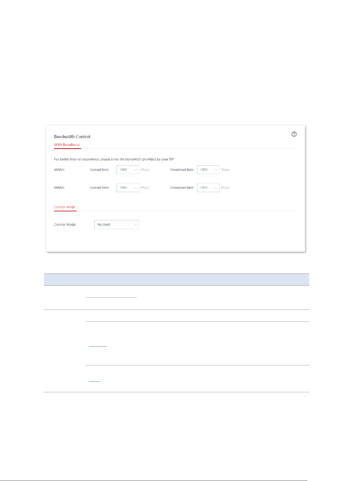
Version 1.0
91
3.7 Bandwidth control
3.7.1 Overview
On this page, the network administrator can control the rate of users, so the limited
bandwidth can be properly distributed.
Click Bandwidth Control to enter the page. See the following figure.
Parameter description
Parameter
Description
WAN
Broadband
Upload Rate
Enter your bandwidth value. If you do not know for sure, please
contact your ISP.
Download Rate
Control Mode
No Limit
No limitations are set on the upload/download rate of LAN users.
Manual
The network administrator, based on the actual conditions, set the
maximum upload/download rate for each connected client, or set
an upload/download rate for all the connected clients.
The manual control mode is more flexible compared with the limit
by group control mode.
Auto
The system, based on the WAN upload/download rate set on the
Bandwidth Control page, evenly distributes bandwidth to LAN
users.
Page 99
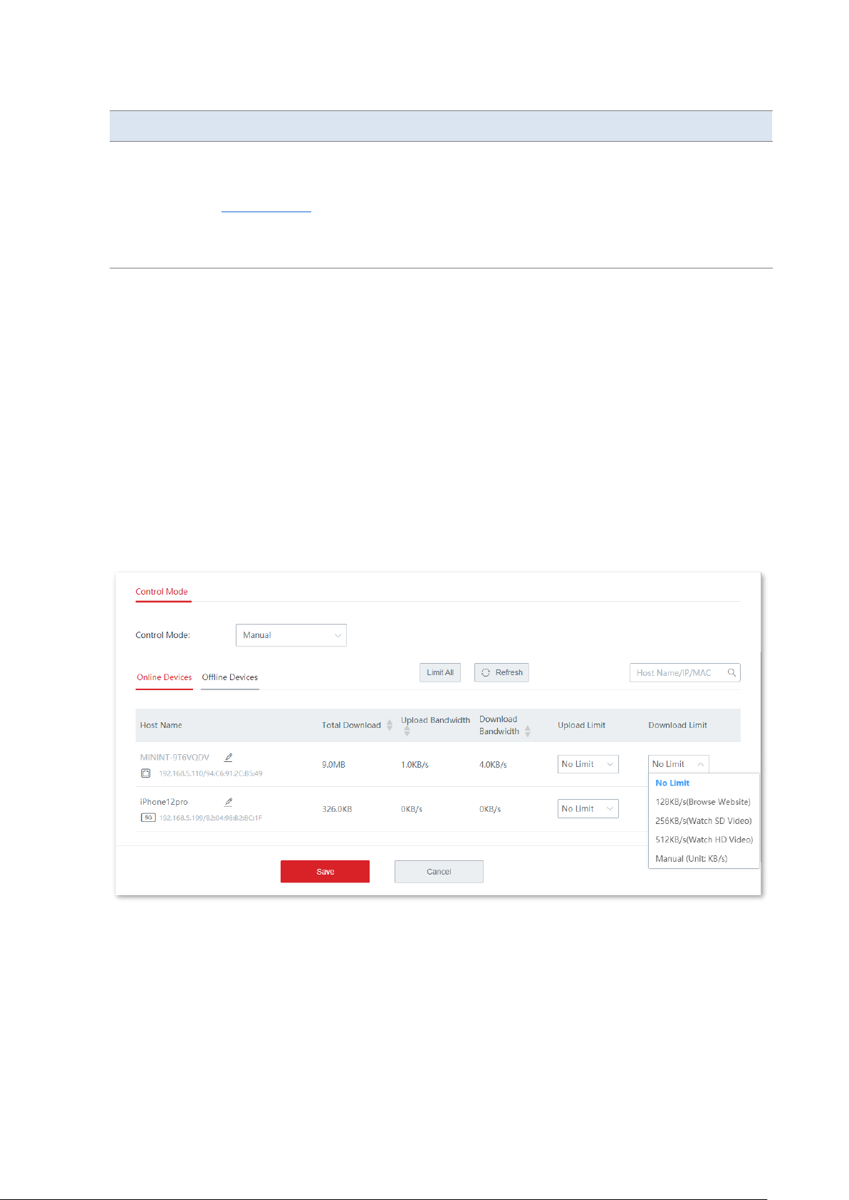
Version 1.0
92
Parameter
Description
Limit By Group
The network administrator, based on the actual conditions, sets
rate limit rules for different groups.
The network administrator controls the dedicated or shared
upload/download rate for users in the specified IP group in the
specified time group, and also, sets the concurrent sessions for each
client.
3.7.2 Manual
◼
Scenario 1: Assume that you want to separately set the maximum upload/download rate for
connected clients
Configuration procedures:
1. Click Bandwidth Control.
2. Set Control Mode to Manual.
3. Choose Online Devices or Offline Devices as required. Online Devices is used for illustration
in the following figure.
4. Set the maximum upload/download rate for the target client.
5. Click Save.
----End
Page 100
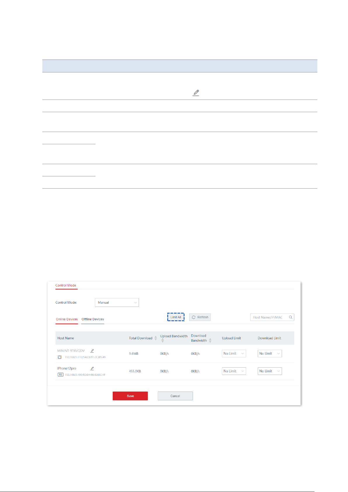
Version 1.0
93
Parameter description
Parameter
Description
Host Name
It specifies the basic information of the client, including the reported client name, the
way the client connects to the cable-free network, IP address, and MAC address. You
can modify the host name by clicking as required.
Total Download
It specifies the total volume of the download data.
Offline Time
It specifies the time when the client got offline. This parameter Is available only when
you choose Offline Devices.
Upload Bandwidth
It specifies the real-time upload/download rate of the client.
1 Mbps=128 KB/s=1024 kb/s.
Download
Bandwidth
Upload Limit
It specifies the maximum upload/download rate the client can use.
Download Limit
◼
Scenario 2: Assume that you want to set a maximum upload/download rate for all the online
or offline clients in the LAN
Configuration procedures:
1. Click Bandwidth Control.
2. Set Control Mode to Manual.
3. Choose Online Devices or Offline Devices as required. Online Devices is used for illustration
in the following figure.
4. Click Limit All.
5. Set a maximum upload and download rate for all the online (offline) clients in the LAN, and
click Save.
 Loading...