

Page 1
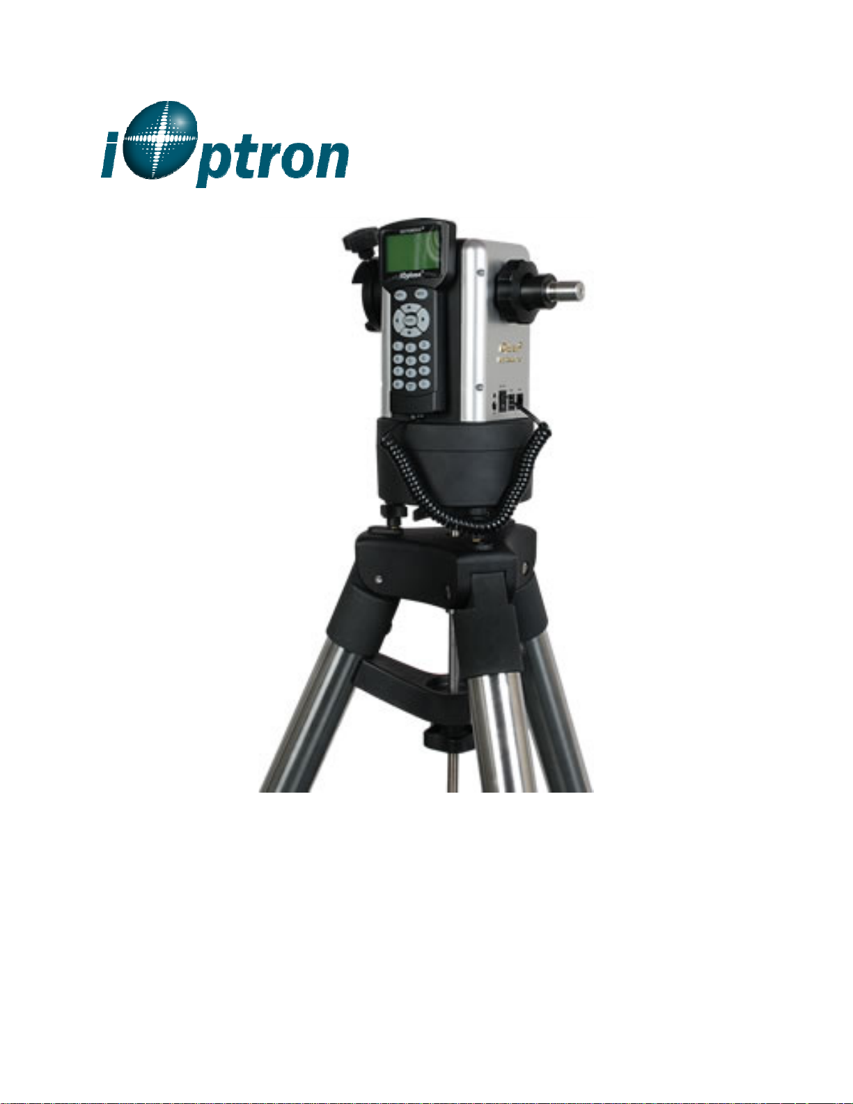
SmartStar® MiniTower Pro
Instruction Manual
TM
Page 2

Table of Content
Table of Content ............................................................................................................................. 2
1. MiniTower
1.1. MiniTower
1.2. MiniTowerTM Components .................................................................................................. 7
2. MiniTowerTM Assembly ............................................................................................................. 8
2.1. MiniTower Assembly .......................................................................................................... 8
2.2. OTA Mounting and Balancing........................................................................................... 10
2.3. Operate a MiniTower on Batteries ..................................................................................... 11
3. GOTONOVATM 8401 Hand Controller .................................................................................... 12
3.1. Key Description ................................................................................................................. 12
3.2. The LCD Screen ................................................................................................................ 13
3.3. Connection to a Computer ................................................................................................. 13
4. Getting Started .......................................................................................................................... 14
4.1. Level and Align the Mount ................................................................................................ 14
4.1.1. Level the Mount. ......................................................................................................... 14
4.1.2. Initial Positions ........................................................................................................... 14
4.2. Setting Up the Mount ......................................................................................................... 14
4.2.1. Set Up Time Zone ....................................................................................................... 15
4.2.2. Set Up Daylight Saving Time ..................................................................................... 16
4.2.3. Set Mount Type ........................................................................................................... 16
4.2.4. Set Anti-backlash ........................................................................................................ 16
4.2.5. Go to the Moon ........................................................................................................... 17
4.2.6. Initial Star Alignment ................................................................................................. 17
4.3. Turn Off the Mount ............................................................................................................ 17
5. Use the MiniTower ................................................................................................................... 17
5.1. Manual Operation of a Telescope ...................................................................................... 17
5.2. Slew to an Object ............................................................................................................... 18
5.2.1. Planets, Sun, Moon ..................................................................................................... 18
5.2.2. Deep sky objects ......................................................................................................... 18
5.2.3. Comets ........................................................................................................................ 18
5.2.4. Asteroids ..................................................................................................................... 18
5.2.5. Stars: ........................................................................................................................... 18
5.2.6. Constellations .............................................................................................................. 18
5.2.7. User Objects ................................................................................................................ 18
5.2.8. Enter R.A. DEC .......................................................................................................... 19
5.3. Sync to Target .................................................................................................................... 19
5.4. Electric Focuser ................................................................................................................. 19
5.5. Set Up Controller ............................................................................................................... 19
5.5.1. Set Up Local Time ...................................................................................................... 19
5.5.2. Set Up Site .................................................................................................................. 19
5.5.3. Set N/S Hemisphere .................................................................................................... 19
5.5.4. Set Display Contrast ................................................................................................... 19
5.5.5. Set Eyepiece Light ...................................................................................................... 19
5.5.6. Set Backlight ............................................................................................................... 19
TM
Overview.............................................................................................................. 4
TM
Features ......................................................................................................... 4
2
Page 3
5.5.7. Set Anti-backlash ........................................................................................................ 19
5.5.8. Set Key Beep............................................................................................................... 19
5.5.9. Set Mount Type ........................................................................................................... 19
5.5.10. Reset All.................................................................................................................... 19
5.5.11. Update Firmware ...................................................................................................... 20
5.5.12. Set gear ratio ............................................................................................................. 20
5.5.13. Set Language ............................................................................................................. 20
5.6. Align .................................................................................................................................. 20
5.6.1. One Star Align ............................................................................................................ 20
5.6.2. Two Star Align ............................................................................................................ 20
5.6.3. Three-Star Align ......................................................................................................... 20
5.6.4. Dis R.A axis error ....................................................................................................... 20
5.6.5. Test Anti-backlash ...................................................................................................... 20
5.6.6. Polaris Position ........................................................................................................... 20
5.7. PEC Option ........................................................................................................................ 20
5.8. Set Up Tracking ................................................................................................................. 21
5.9. User Objects ....................................................................................................................... 21
5.10. Auto Guide ....................................................................................................................... 21
5.11. Park Scope ....................................................................................................................... 21
5.12. To Park Position ............................................................................................................... 21
6. Maintenance and Servicing ....................................................................................................... 21
6.1. Maintenance ....................................................................................................................... 21
6.2. Troubleshooting ................................................................................................................. 21
6.3. iOptron Customer Service .................................................................................................. 22
Appendix A. Technical Specifications ......................................................................................... 23
Appendix B. GOTONOVATM 8401 HC MENU STRUCTURE .................................................. 24
Appendix C. GOTONOVATM Star List ........................................................................................ 26
Appendix D. Set Up USB-PC Connection ................................................................................... 31
Appendix E. Firmware Upgrade ................................................................................................... 38
Appendix F. Use a PC to Control an iOptron Mount ................................................................... 41
Appendix G. RS-232 Command Set ............................................................................................. 42
IOPTRON TWO YEAR TELESCOPE, MOUNT, AND CONTROLLER WARRANTY ........ 47
WARNING!
NEVER USE A TELESCOPE TO LOOK AT THE SUN!
Looking at or near the Sun will cause instant and irreversible damage to your eye.
Children should always have adult supervision while observing.
3
Page 4
1. MiniTower ProTM
Overview
1.1. MiniTower ProTM Features
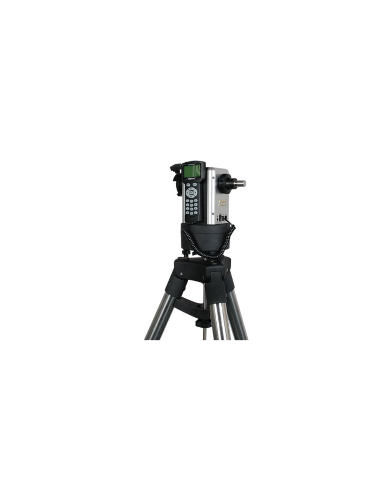
MiniTower ProTM is the perfect combination
of capacity and portability.
33 lbs of Payload
Born out of the popular iOptron CubeTM, The
MiniTower Pro
TM
is the ultimate observing
solution for people who are searching for a
capable and portable GOTO telescope
mount to counter light pollution in their
backyards and for travel convenience. With
a standard payload of 33 lbs, a rock solid 2”
stainless steel tripod, metal worm and gear
and two dovetail adaptors, The MiniTower
TM
Pro
is capable of handling various optical
tube assemblies (OTAs). A 10-lbs counter
weight and a secondary dovetail holder are
provided for balancing an OTA weights
more than 10 lbs, or for a secondary OTA.
Figure 1. MiniTower Pro Mount and Tripod
Extremely Portable
With all the standard components
(excluding the tripod) fitted in an aluminum
alloy metal case, The MiniTower Pro
easily travel in a car or taken as airline
TM
can
luggage. The system takes about 10
minutes to assemble. This unlimited
portability combined with the internal GPS
gives amateur astronomers real flexibility in
selecting an observing site.
Page 5

Figure 2. MiniTower Pro in an aluminum case
Accurate GOTO and Tracking
Equipped with our SmartStar® GOTO
technology, the MiniTower Pro
the most powerful and accurate GOTO
mounts available on the market. The
standard 8401 hand controller offers a
superb navigation experience with an 8-line
LCD backlit display, a 130,000-object
database, and a USB port for easy
TM
is one of
connection with ASCOM compliant PC
planetarium programs. With a typical GOTO
accuracy of 1 arc minute and the
SmartStar
MiniTower Pro
celestial object of your choice to the center
of the eyepiece and keep tracking for
hours.
®
precision auto-tracking, The
TM
will consistently bring the
5
Page 6
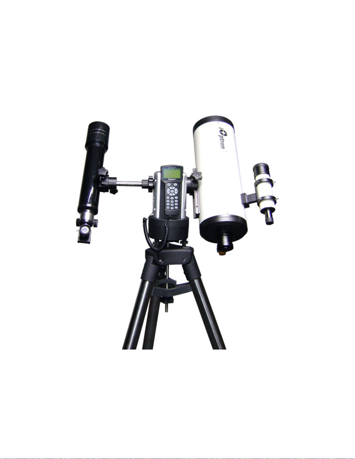
Additional Unique Features
Equipped with additional features such as
automatic over-current protection, automatic
clutch protection for both axes, easy 3-point
level adjustment, dual scope setup with two
dovetails and more-- The MiniTower Pro
is one of the most user-friendly GOTO
mounts available today.
TM
Figure 3. MiniTower Pro with dual scope setup
6
Page 7
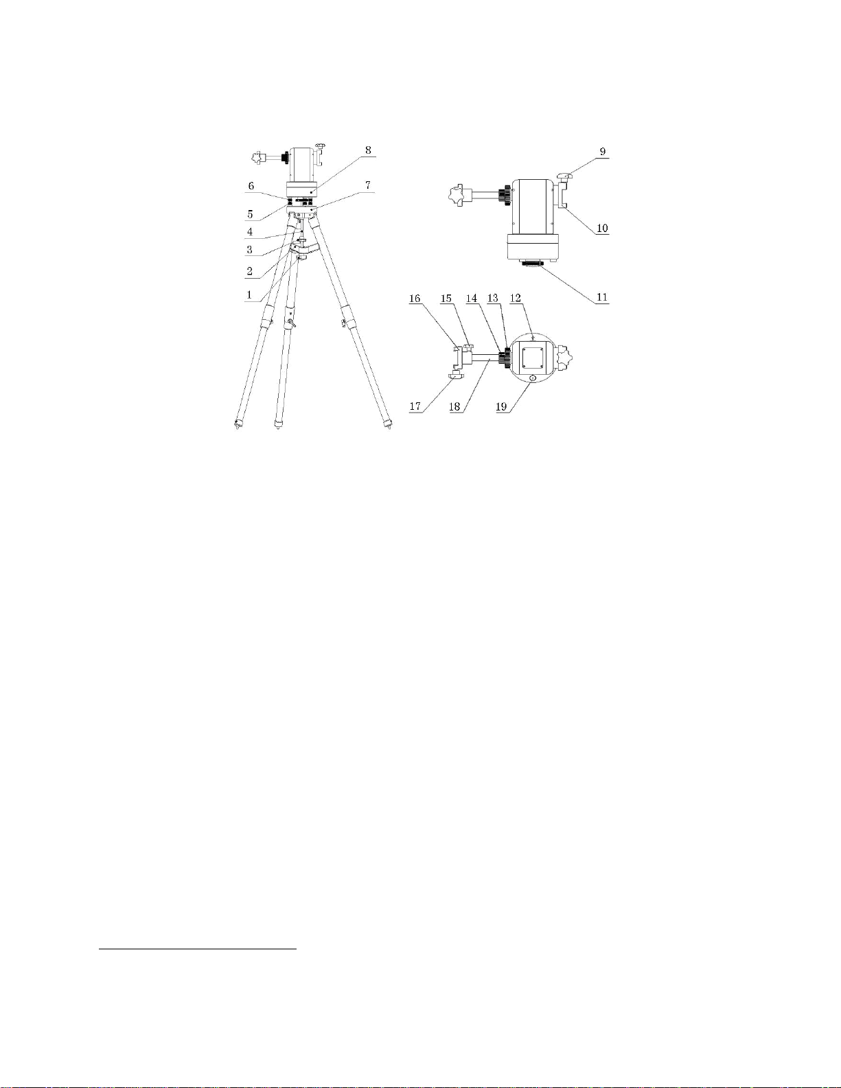
1.2. MiniTower ProTM Components1
Figure 4. MiniTower Pro Components
Shown in the picture:
1. Tripod Lock
2. Tripod Support
3. Tripod Knob
4. Tripod Rod
5. Level Adjustment Lock
with MiniTower Pro)
6. Level Adjustment Screw
7. Tripod
8. Mount Base
9. Primary Dovetail Lock
Not shown in picture:
• 8401 Hand Controller
• Controller Cable
• AC Adapter
• 12V DC Adapter with Car Lighter Plug
• USB Cable
• Counter Weight
• Counter Weight Lock Pin
• Counter Weight Lock
• Hard Travel Case
(not included
10. Primary Dovetail Holder
11. Azimuth Clutch Lock
12. South Alignment Mark
13. Altitude Clutch Lock
14. Counter Balance Shaft Lock
15. Secondary Dovetail Holder Lock
16. Secondary Dovetail Holder
17. Secondary Dovetail Lock
18. Retractable Counter Weight Shaft
19. Bubble Level Indicator
1
The contents may vary slightly by generation.
7
Page 8
2. MiniTower ProTM Assembly
There are two shipping boxes. One box contains the hard case and mount components. The
other box contains the tripod and counterweight.
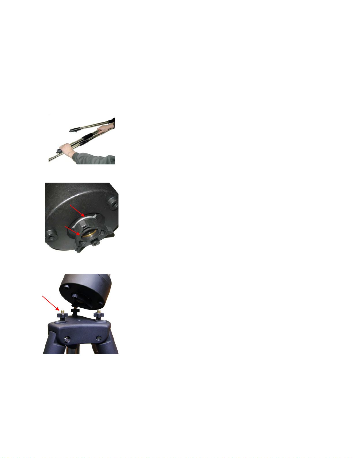
2.1. MiniTower Pro Assembly
1. Setup tripod. Extend tripod legs to full extension. Then lock
legs using the lock knobs on sides.
Next expand the legs out to their maximum position.
Figure 5
2. Assemble the three prong washer and azimuth clutch lock
(#11) onto the mount base
Washer
#6
#11
Figure 6
3. Carefully position telescope mount onto the tripod by aligning
the three holes on the bottom of the mount base (#8) to the
three level adjustment screws (#6) on the top of the tripod (#7),
hold the mount with your hands.
Adjust level adjustment screws (#6) to level the mount using the
bubble level on the base.
Figure 7
8
Page 9
#4 Rod
#3 Knob
#1
Figure 8
#2
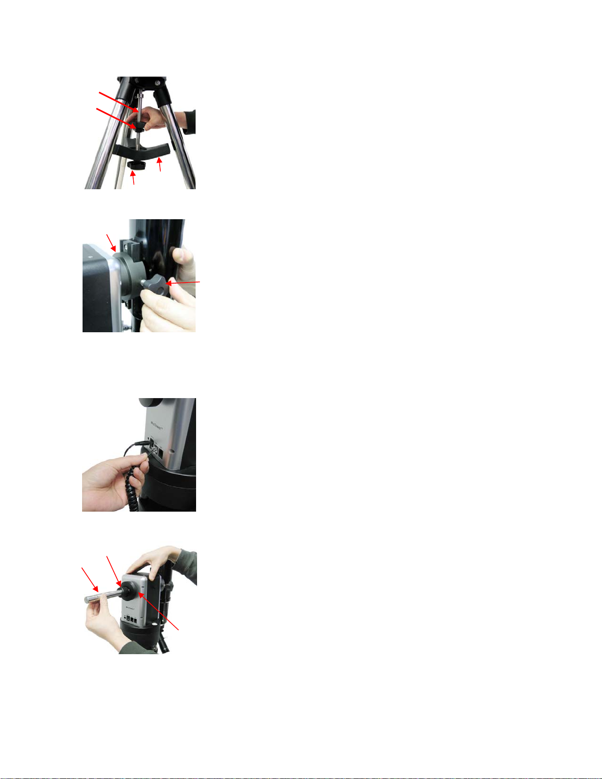
4. Secure the mount to the tripod by using the long tripod rod
(#4). Hand tighten the rod into the bottom of the mount by
turning the tripod knob (#3).
Next, slide tripod support (#2) onto bottom of rod (#4). Position
the three edges to fit against the three tripod legs. Then hand
tighten tripod lock knob (#1) to secure the tripod support in
place.
#10
Figure 9
Figure 10
5. Attach an OTA to the primary dovetail holder (#10) using the
primary dovetail lock (#9).
Tighten both the azimuth clutch lock (#11) and the altitude
clutch lock (#13)
#9
6. Plug one end of supplied 6pin RJ-11 cable into either one of
the two HBX (Handbox) sockets on the mount; plug the other
end into the GOTONOVA 8401 hand controller. Plug in 12V
power cable.
Turn on power. Now you are ready to observe. Use the 4 Arrow
keys (▲▼◄►) to rotate the scope Up, Down, Left, and Right.
Use the number key to change the slew speed from the slowest
(1:1X) to the fastest (9:MAX).
The other HBX is reserved for accessories, such as electronic
focuser, laser pointer and autoguider adapter. DO NOT plug
non-iOptron accessories into the unit to avoid damaging
the mount or accessories.
#18
#14
7. This step allows you to attach the counterweight or a second
scope. (note: if you have a light scope less than 10 lbs. on the
primary side, then attaching a counterweight is optional).
First, make sure the altitude clutch lock (#13) is tight. Loose the
counter weight shaft lock (#14), pull the counter weight shaft
#13
(#18) out and tighten the counter balance shaft lock (#14).
Figure 11
9
Page 10
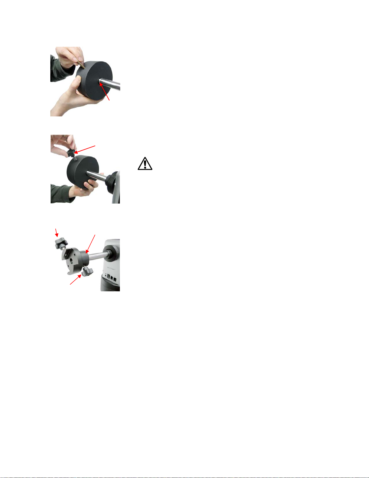
Figure 12
If you are attaching a second scope, do not add the
counterweight. Instead, skip to Step 10 to add a second
scope.
8. Slide the counterweight onto the counterbalance shaft (#18).
Next, insert the brass pin into the hole on the counterweight.
groove
#17
#15
Lock
Figure 13
#16
Figure 14
9. Secure the counterweight by tightening the lock knob.
Counter weight is heavy. Please handle with care
to avoid injury!
This step is for attaching a second scope.
10. Attach Secondary Dovetail Holder (#16) by tightening the
holder lock (#15) onto the counterweight shaft (#18).
After sliding your scope into the dovetail holder—secure the
scope by tightening the secondary lock (#17)
2.2. OTA Mounting and
Balancing
The iOptron MiniTower Pro™ can handle
various OTAs. A dovetail plate is needed to
mount an OTA onto the MiniTower Pro
mount. The width of the MiniTower Pro
dovetail holder is 1.75”.
Most telescopes come with a dovetail plate
installed on the bottom of the telescope. If
the size of dovetail plate does not match unscrew the plate and install an appropriate
TM
dovetail plate that matches the holder. 1.75”
dovetail plates are available from iOptron at
www.iOptron.com (part number #8422) or
visit an online or local camera store.
Some telescopes may not have screw holes
on the bottom. In this case you may need
compatible mounting rings to attach the
dovetail plate. The size of the mounting
rings should match the aperture of your
OTA.
The counter weight (CW) is always helpful
to balance the OTA in order to have smooth
10
Page 11
and accurate GOTO and tracking. The
heavier the OTA, the more necessary it is
to use a CW. For lightweight OTAs, i.e. 5-6
lbs, however, the CW may not be necessary.
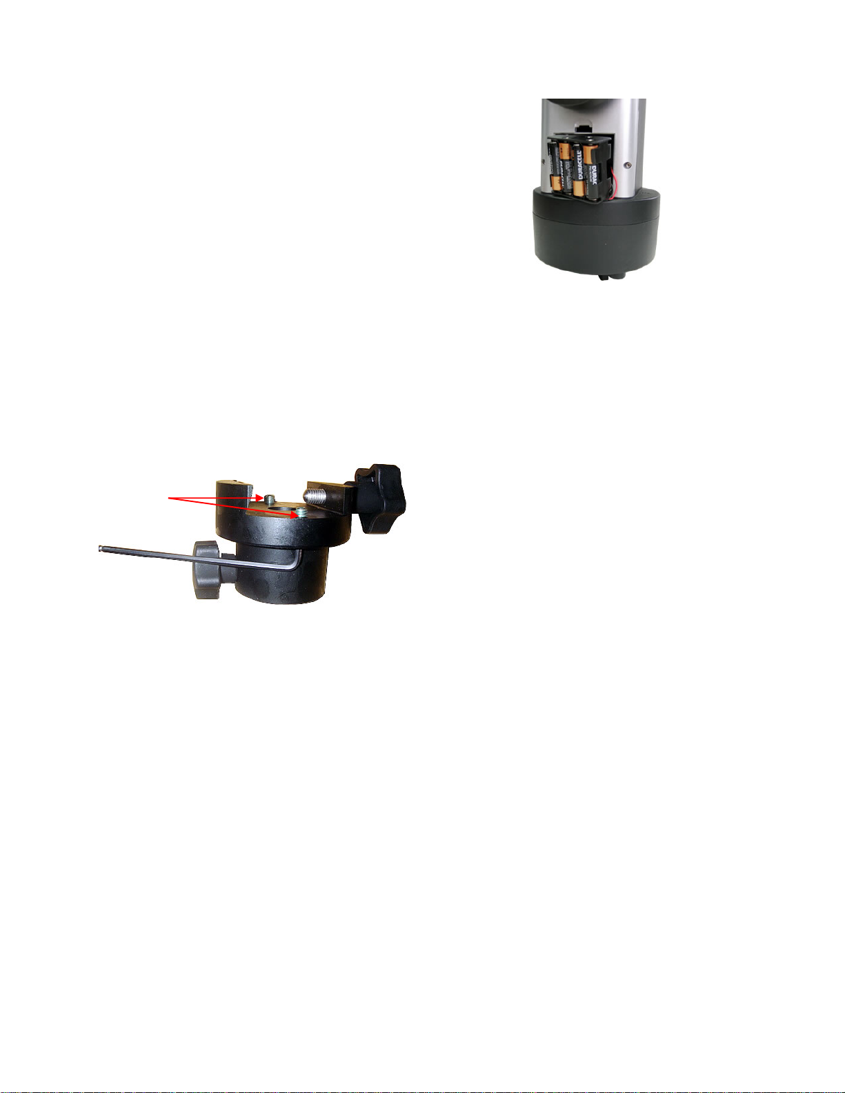
If you have a secondary OTA on the
secondary dovetail holder, make sure you
align it with the primary OTA. This alignment
is done easier during the daytime. Point the
primary telescope to a target at a remote
building or flagpole and center the target in
the eyepiece. Loosen the secondary
dovetail holder lock (#15). Rotate the
secondary OTA around the counter balance
shaft (#18). Center the object in the
eyepiece of the secondary OTA. If the
secondary OTA is tilted, it can be adjusted
by two tilting adjustment screws as shown in
Figure 15 (M6 x 12mm Allen set screws, not
supplied).
M6 set screws
Figure 16. Battery compartment for
MiniTower Pro™
The mount will draw a significant amount of
current when performing GOTO and slew
operations. The battery operation time
varies depending on the battery quality and
operation conditions. It could last from
couple of hours to tens of hours. Use only
fresh batteries and do not mix fresh and old
batteries. Insufficient battery power may
cause error messages.
Figure 15. Secondary Dovetail and set
screws
A combination of a light OTA and a CW can
be used to balance a heavier primary OTA.
2.3. Operate a MiniTower Pro on
Batteries
To install batteries open the battery
compartment door. Pull the battery holder
out from the mount carefully making sure
not to pull the wires loose. Insert 8 AA
batteries (not included) according to the
diagram on the holder. Replace the battery
holder back to the battery compartment and
replace the cover. (See Figure 16)
11
Page 12
3.
4. GOTONOVA
TM
8401 Hand Controller
HBX
Port
USB
Port
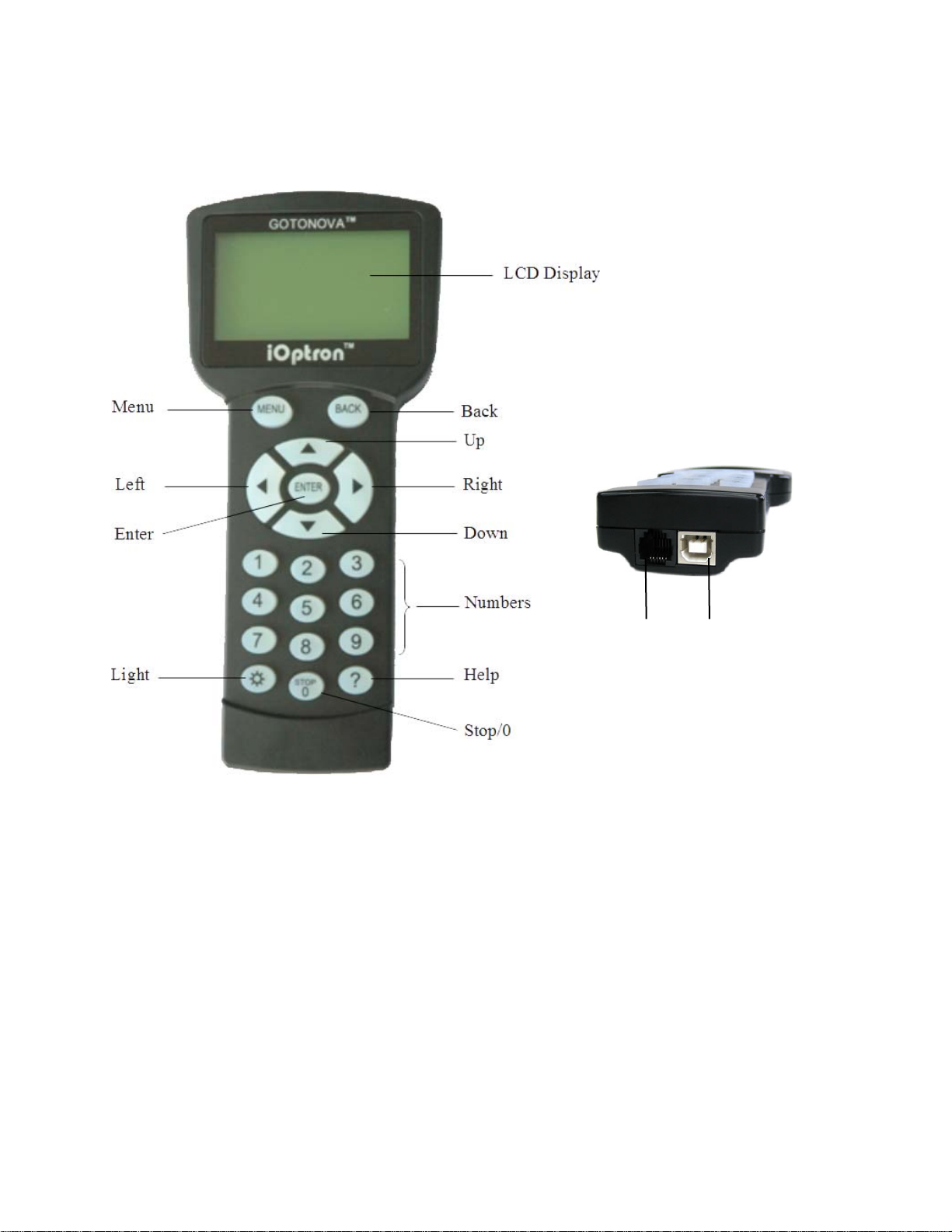
Figure 17. GOTONOVA 8401 Hand Controller
GOTONOVATM 8401 hand controller (HC) is the standard controller for a MiniTower Pro, as
shown in Figure 17.
• ENTER: Confirm an input, go to the next
4.1. Key Description
• MENU: Press “MENU” to enter the Main
Menu.
• BACK: Move back to the previous
screen, or end/cancel current operation,
such as slewing.
menu, select a choice, or slew the
telescope to a selected object.
• Arrow (▲▼►◄): Press ▲▼ buttons to
move a telescope along the DEC
direction, ►◄ to move a telescope
along the RA direction. Brows the menu
or move the cursor in operating menu.
• Number Keys: Input numerical values.
Also used to adjust speeds (1: 1X; 2:
12
Page 13
2X; 3: 8X; 4: 16X; 5: 64X; 6: 128X; 7:
256X; 8: 512X; 9: MAX)
• Light Key(☼): Turns on/off the red LED
reading light on the back of the
controller.
• ? Key: For help or extra information.
• STOP/0 Key: Stop/Start tracking.
• HBX (Handbox) port: connect the HC to
MiniTower Pro mount using a 6-wire
RJ11 cable.
• USB port: connect the HC to a
Computer via a USB cable.
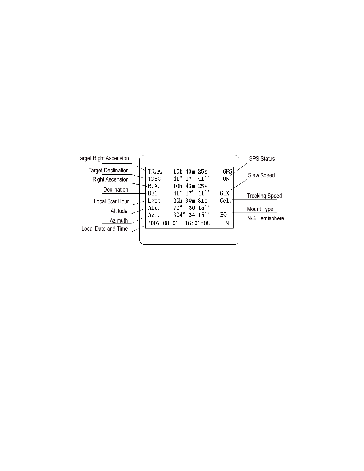
4.2. The LCD Screen
The 8401 HC is designed to use for both
iOptron’s equatorial (EQ) mount, such as
the SmartStar
Equatorial Mount and the GOTONOVA
Equatorial Kit, and AltAzimuth (A/A) mount,
which includes all SmartStar
mounts and telescopes. It consists of a
large 8-line LCD screen, which displays all
the information as shown in Figure 18. The
user interface is simple and easy to learn.
®
-PR GOTO German
®
GOTO
TM
Figure 18. 8401 HC LCD Information Screen
• GPS status: When the power is turned on, it shows “GPS ON”, which means a GPS
receiver is connected. When the GPS receiver finds the satellite and receives GPS
signal, it shows “GPS OK”. The “GPS OK” may turn off after few minutes.
• Slew speed: It has 9 speeds: 1X, 2X, 8X, 16X, 64X, 128X, 256X(1º/sec),
512X(2º/sec), MAX(4º/sec).
• Tracking speed: It has 4 speeds: Cel (celestial), Sol (Solar), Lun (Lunar), Def (user
defined)
• Mount Type: EQ is equatorial and A/A altazimuth.
4.3. Connection to a Computer
The GOTONOVA hand controller has a
USB port which can be connected to a
computer. This will allow Firmware
Upgrading, Database Updating, or
Planetarium application. A USB2COM driver
is needed to simulate the USB port to a RS232 serial port. (see Appendix D)
The MiniTower Pro
number of popular astronomy software
programs. For astronomy software that
does not have an embedded iOptron mount
driver, an ASCOM driver and related
platform are needed. Please refer to
Appendix F for more information.
TM
can be controlled by a
13
Page 14
5. Getting Started
5.1. Level and Align the Mount
In order to experience the full GOTO
capability of GOTONOVA technology it is
very important to set up the mount correctly
before observation.
First, loosen tripod rod (#4) and tripod lock
(#1) a little. Then loosen azimuth clutch lock
(#11) half turn. Check the bubble level
indicator (#19), adjust the level adjustment
screws (#6), and center the bubble in the
indicator. Turn the mount by a hand and
make sure that the mount is leveled on all
sides while turning. Adjust the level
adjustment screws again if the bubble is not
centered while turning.
Tighten the azimuth clutch lock (#11).
Tighten the tripod knob (#3). Tighten the
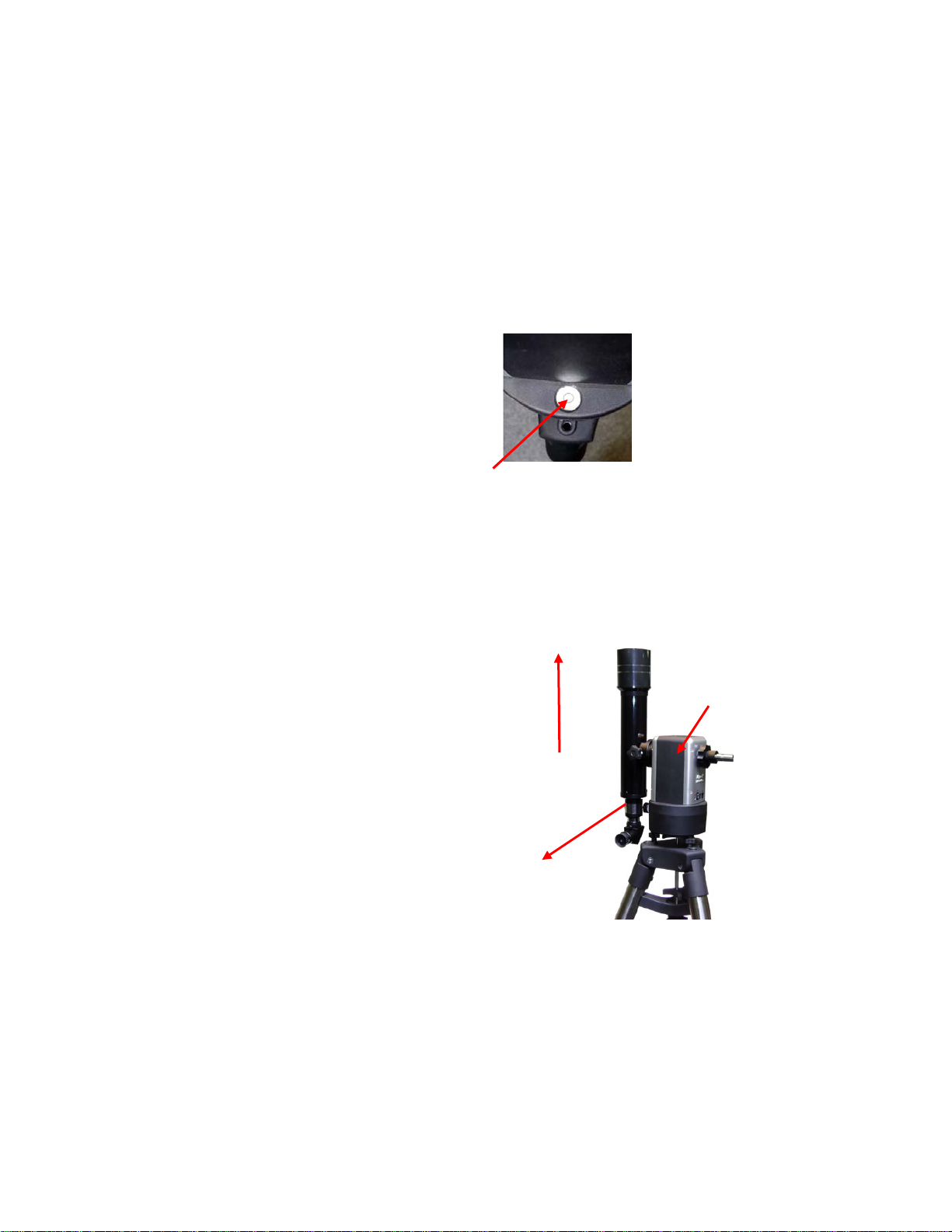
5.1.2. Initial Positions
Each time the Mount is turned on, the
default position is Parking Position, i.e.,
altitude is 90º0’0” and azimuth is 180º0’0”,
5.1.1. Level the Mount.
Leveling is critical for a good GOTO and
tracking accuracy.
tripod lock (#1). Make sure the mount is
always leveled.
Figure 19
which means the “SOUTH” mark is pointing
to south and the telescope is pointing
straight up at the zenith. To set the Park
Position, you can:
Face the South. Align the Mount to south
by turning the South mark facing south. An
additional compass is needed. There are
two ways to do so. One is loosen the
azimuth clutch lock (#11) a little and
manually turn the Mount to face south. Then
tighten the azimuth clutch lock again. The
other is turn on the mount. Turn the mount
facing south using hand control. Then turn
off the power. Note: Do not put the
compass directly on top of the mount. The
motor parts of the mount could affect the
pointing accuracy of the compass.
Point to Zenith. Unlock the altitude clutch
lock (#13) and rotate the telescope to point
up directed at the Zenith. A torpedo level
may help.
Once it is straight re-tighten the altitude lock
to make sure OTA is secure and will not
spin.
(2) Up
(1) South
#13
Figure 20
5.2. Setting Up the Mount
A MiniTower Pro is equipped with a GPS
receiver, which will receive the local time,
14
Page 15

longitude and latitude information from
satellites after the link is established.
However, manual input is still needed for
time zone and Daylight Saving setting.
A clear sky outside is needed for GPS to
communicate well with the satellites.
5.2.1. Set Up Time Zone
Press MENU button, from the main menu,
scroll down and select “Set up controller”
Select and slew
Sync. to target
Electronic focuser
Set up controller
Align
PEC option
Set up Tracking
User objects
Press ENTER. Scroll down and select “Set
up site”
Set up Local Time
Set up site
Set N/S hemisphere
Set display contrast
Set Eyepiece light
Set Backlight
Set anti-backlash
Set Key Beep
Press ENTER. The longitude and latitude
coordinates will be updated when the GPS
picks up satellite signals. “W/E” means
west/east hemisphere; “N/S” means
north/south hemisphere; “d” means degree;
“m” means minute; and “s” means second.
cursor and using ▲ or ▼ key to toggle
between “W” and “E”, “N” and “S”, using
number key to change the numbers. It is
always a good idea to do your home work to
get the GPS coordinates before traveling to
a new observation site.
The site coordinates information can be
found from internet, such as GPSVisualizer
(http://www.gpsvisualizer.com/geocode
), by
entering the city name or address. In case
you only find the site information in decimal
format you can convert them into d:m:s
format by multiplying the decimal numbers
by 60. For example, N47.53 can be
changed to N47º31'48”: 47.53º = 47º
+0.53º, 0.53º=0.53x60'=31.8',
0.8'=0.8x60"=48". Therefore,
47.53º=47º31'48" or 47d31m48s. Same as
N47º31.8’: 31.8’=31’+0.8’, 0.8’=0.8x60”=48”.
Press ◄ or ► key, move the cursor to the
bottom of the screen to set the time zone
information (add or subtract 60 minutes per
time zone). Enter minutes “ahead of” or
“behind” UT (universal time).
• New York City is 300 minutes “behind”
UT
• Los Angeles is 480 minutes “behind” UT
• Rome is 60 minutes “ahead of” UT
• Beijing is 480 minutes “ahead of” UT
• Sydney is 600 minutes “ahead of” UT
All the time zones in North America are
behind UT, as shown in the following table.
So make sure it shows “behind” instead of
“ahead of” UT.
Set up site info:
Longitude:
W071d27m47s
Latitude:
N42d15m40s
300 Min. behind UT
If for any reason your GPS can’t pick up a
signal you can manually enter the GPS
coordinates. Press ◄ or ► key to move the
-
-
-
-
-
-
15
Page 16

To adjust minutes, move the cursor to each
digit and use the number keys to input
number directly. To change the “behind” or
“ahead of” UT, move the cursor to “ahead”
and using ▲ or ▼ key to toggle between
“behind” and “ahead”. When the number is
correct, press ENTER and go back to the
previous screen.
5.2.3. Set Mount Type
The #8401 hand controller that comes with
the MiniTower Pro can function in both EQ
and AltAz. For the MiniTower Pro you will
need to set the hand controller to function in
AltAz. Scroll down and select “Set Mount
Type”,
For other parts of the world you can find
your “time zone” information online at
websites such as
http://www.timeanddate.com/worldclock/
.
DO NOT COUNT DAYLIGHT SAVING
TIME.
5.2.2. Set Up Daylight Saving Time
Set up site
Set N/S hemisphere
Set display contrast
Set Eyepiece light
Set Backlight
Set anti-backlash
Set Key Beep
Set Mount Type
Scroll up and select “Set up local Time”
Set up Local Time
Set up site
Set N/S hemisphere
Set display contrast
Set Eyepiece light
Set Backlight
Set anti-backlash
Set Key Beep
Press Enter.
Equatorial Mount
Alt/Azi Mount
Select Alt/Azi mount and press ENTER to
go back the previous screen.
Press ENTER.
Set local time:
2008-06-01 11:55:09
Daylight Saving Time Y
Use the ◄ or ► key to move the cursor to
the bottom of the screen, use the ▲ or ▼
button to toggle between “Y” and “N”. Press
ENTER to go back the previous screen. The
local time also can be manually entered in
case of GPS malfunction or testing the
mount inside.
5.2.4. Set Anti-backlash
For an Alt/Azi operation, both R.A. and
DEC anti-backlash should be set to 0
step. Scroll down and select “Set anti-
backlash”
Set up Local Time
Set up site
Set N/S hemisphere
Set display contrast
Set Eyepiece light
Set Backlight
Set anti-backlash
Set Key Beep
The time and site information will be
stored inside HC memory chip. If you are
not traveling to other observation site,
they do not need to be changed.
16
Page 17

Press ENTER. A R.A. anti-backlash will
display:
R.A. anti-backlash:
0150 steps
One steps equal to
1.5 arc second.
To adjust steps move the cursor to each
digit and use the number keys to input
number directly. Press ENTER – “DEC antibacklash” will display:
DEC anti-backlash:
0150 steps
One steps equal to
1.5 arc second.
5.2.6. Initial Star Alignment
A simple star alignment/synchronization can
be performed to improve the GOTO and
tracking accuracy. To do so, after slew the
mount to an object, such as Moon, press
MENU button, scroll down to “Sync. To
Target”, follow the on-screen instruction and
press ENTER.
An alternate way is to perform an “Easy
One Star Align”. To do so, press MENU
button, scroll down to “Align”, select “Easy
One Star Align” and press ENTER. The
screen will list three bright objects for you to
select from (ex. Moon, Jupiter, Venus).
Select an object using ▲ or ▼ key. Then
press ENTER. Next use the arrow keys to
slew to the object until it is centered in your
eyepiece. Then press ENTER.
You may need to use the number keys to
change the slewing speed to make the
centering procedure easier.
Move the cursor to each digit and use the
number keys to set the anti-backlash to 0.
Press ENTER to go back the previous
screen.
Press BACK button to go back to main
menu.
5.2.5. Go to the Moon
After performing these set-ups the mount is
ready to GOTO and track objects. One of
the most common objects is the Moon.
To slew to the Moon press MENU button.
Select “Select and slew” by pressing the
ENTER button. Select “Planets, Sun,
Moon”, and use the ▲ or ▼ buttons to
select Moon. Press ENTER. The telescope
will automatically slew to the Moon and lock
on. It will automatically begin to track once it
locks on. Use the arrow keys to center the
Moon in your eyepiece if it is not centered.
Or for better performance use Sync to
Target (see instructions later).
5.3. Turn Off the Mount
When you are finished observing it is
recommended to return the mount to Park
Position. If the mount is not moved then no
initial set up is needed when you turn on the
mount next time. To park the telescope
press the MENU button, scroll down to
“Park Telescope” and press ENTER. Once
the telescope returns to Park Position turn
the power off.
6. Use the MiniTower Pro
6.1. Manual Operation of a
Telescope
You may observe land and astronomical
objects using GOTONOVA’s arrow keys.
After the telescope was assembled
(referring to Section 2. Telescope
Assembly), flip the I/O switch on the
telescope mount to turn on the mount. Use
►,◄,▼ or ▲ buttons to point the telescope
to the desired object. You may need to use
17
Page 18

the number keys to change the slewing
speed. Simply press a number while
slewing to change the slew speed.
• MCG Catalog: consists of 29004
objects. They are listed numerically from
MCG+15 to MCG-05.
6.2. Slew to an Object
Press the MENU button. From the main
menu, select “Select and Slew.” Select an
object that you would like to observe and
press the ENTER key.
The GOTONOVA
has a database of about 130,000 objects.
Use the ► or ◄ buttons to move the cursor
and the ▼▲ buttons to change the
individual number. The check mark (√)
indicates the object is above the horizon,
and a cross mark (X) means it is below the
horizon. In some catalogs those stars below
the horizon will not display on the hand
controller.
6.2.1. Planets, Sun, Moon
There are 10 objects in the Solar system
catalog.
TM
8401 hand controller
• Caldwell Catalog: consists of 109
objects.
• Abell Catalog: consists of 2712 objects.
• Herschel Catalog: consists of 400
objects.
6.2.3. Comets
This catalog contains up to 190 comets.
This database is customer upgradeable.
6.2.4. Asteroids
This catalog contains up to 4096 asteroids.
This database is customer upgradeable.
6.2.5. Stars:
• Named Stars: consists of 191 stars with
their common names. They are listed
alphabetically. A list is attached in
Appendix C.
6.2.2. Deep sky objects
This menu includes objects outside our
Solar system such as galaxies, star
clusters, quasars, and nebulae.
• Named Deepsky Objects: consists of 60
deep sky objects with their common
names. A list of named deep sky objects
is attached in Appendix C.
• Messier Catalog: consists of all 110
objects.
• NGC IC Catalog: consists of 7840
objects in NGC catalog and 5386 objects
in IC catalog. To select an object from
NGC or IC catalog, move the cursor to
NGC, using▲ or ▼ button to toggle
between NGC and IC. Then move the
cursor to numerical position and use the
number button to select the object.
• UGC Catalog: consists of 12939
objects.
• Double Stars: consists of 40 double
stars. A list is attached in Appendix C.
• GCVS Variable Stars: consists of 38624
GCVS variable stars. They are listed
numerically.
• SAO Catalog: consists of 26584 SAO
catalog objects. They are listed
numerically.
6.2.6. Constellations
This catalog consists of 88 modern
constellations with their names. They are
listed alphabetically. A list is attached in
Appendix C.
6.2.7. User Objects
This catalog can consist up to 256 user
predefined objects. These objects need to
be entered before they can be selected for
slewing.
18
Page 19

6.2.8. Enter R.A. DEC
6.5.2. Set Up Site
Here you can go to a target by entering its
R.A. and DEC numbers.
6.3. Sync to Target
This operation will match the telescope's
current coordinates to Target Right
Ascension and Declination. After slew to an
object, press MENU—then scroll to “Sync to
Target” and press ENTER. Follow the
screen to do the sync. Using this function
will re-calibrate the computer to the
selected object. Multiple syncs can be
performed if needed.
“Sync to Target” will only work after “Select
and slew” is performed. Otherwise, the
system may perform incorrectly. You can
change the slewing speed to make the
centering procedure easier. Simply press a
number (1 through 9) to change the speed.
The default slew speed is 64X.
“Sync to Target” does the same thing as
one star alignment except that you choose
the object to “sync” to. One star alignment
chooses the star/object for you.
6.4. Electric Focuser
Refer to 4.2.1.
6.5.3. Set N/S Hemisphere
Set north or south hemisphere.
6.5.4. Set Display Contrast
Use arrow keys to adjust LCD display
contrast.
6.5.5. Set Eyepiece Light
If you have an illuminated-reticule eyepiece
or illuminated polar scope, and it is
supported by GOTONOVA hand controller-use this option to adjust the light intensity.
6.5.6. Set Backlight
Adjust LCD and keypad backlight.
6.5.7. Set Anti-backlash
Use Array Keys to move the cursor and
Number Keys to change the number. 0 is
suggested for Alt/Azi mount. For an EQ
mount, the default setting is 150 for both
DEC and R.A.
If you have an electric focuser in your
system and it is supported by GOTONOVA,
use this option to adjust the focuser. Use
◄► for coarse tuning and ▼▲ for fine
tuning.
Refer to your Electric Focuser operation
manual for detailed instruction.
6.5. Set Up Controller
6.5.1. Set Up Local Time
Refer to 4.2.2.
6.5.8. Set Key Beep
Turn the key beep on/off.
6.5.9. Set Mount Type
Although MiniTower Pro is an Alt/Azi mount
the controller can be used for either
Equatorial Mount or Alt/Azi Mount. This
command changes between the two
positons (EQ and AltAz).
6.5.10. Reset All
Reset all settings to factory default data.
19
Page 20

6.5.11. Update Firmware
Firmware updating using iOptron
Downloader through USB port on hand
controller. (Refer to Appendix E.)
6.5.12. Set gear ratio
second star. If the star you choose is too
close to the first one, the system will let you
choose another one. When you are aligned
with the second star, two star alignment is
finished. You can reject the suggested star
if it is blocked by the tree or behind the
house.
Reserved for future products.
6.5.13. Set Language
Select hand controller language.
6.6. Align
This function is used for aligning the
telescope. In addition to “Easy One Star
Align,” the system also provides “One Star
Align” and “Two Star Align” for Alt/Azi
mount. “Three Star Align” is only supported
by EQ mode.
6.6.1. One Star Align
From the main menu select “Align”. Select
“One Star Align”. Use ▲ and ▼ buttons to
select a star and press ENTER. A list of
align planets or stars that are above the
horizon is computed based on your local
time and location. Use arrow buttons to
move the telescope and center the star in
your eyepiece. You can use the number
buttons to change the slew speed.
Press ENTER when finished. If your setup
is leveled well, one star alignment should be
sufficient for good GOTO accuracy. To
increase the accuracy you may choose to
do two star alignment.
“Two Star Align” results will be overridden if
“One Star Align” or “Sync. to Target” is
performed after “Two Star Align.”
6.6.3. Three-Star Align
It will increase the accuracy even higher
and requires an even wider view of the sky.
This basically asks you to choose a third
star to align after two-star align. Three star
alignment is not available for Alt/Azi mode.
6.6.4. Dis R.A axis error
This only works for EQ mode. This displays
the celestial pole point error. Point error is
zero when you power on the mount (unless
you “Park Telescope” before powering off.
6.6.5. Test Anti-backlash
This command tests the backlashes in both
R.A. and DEC. The saved numbers will
show in “Set Anti-backlash” menu.
However, if no high accuracy is needed or
your equatorial mount is not a high accuracy
unit (i.e. the worm gear has different
clearance in different positions) you can
omit this procedure.
This command only works for EQ mode.
6.6.2. Two Star Align
Two star alignment will increase the GOTO
accuracy of the mount. It is suggested to do
two star alignment after one star alignment.
Two star alignment requires a wider view of
the sky, since the two align stars need to be
far apart. Select “Two Star Align” in the
Align menu. When you finish the first star,
the system will prompt you to choose the
6.6.6. Polaris Position
This shows Polaris position.
6.7. PEC Option
Periodic Error Correction (PEC) is not
supported in Alt/Azi mode.
20
Page 21

6.8. Set Up Tracking
7. Maintenance and
A user can set up tracking in the main menu
by selecting “Set up tracking”. Then the user
can select “Sidereal speed”, “Solar speed”,
“Lunar speed”, and “User defined speed”.
For “User defined speed” this can be
adjusted from 91% to 109% of sidereal
speed by pressing the ▲or ▼ buttons.
6.9. User Objects
Besides various star lists available in the
hand controller --you can add, edit or delete
your own user-defined objects. All data you
enter is supposedly J2000.0 epoch.
6.10. Auto Guide
This is an advanced function for autoguiding
when a guiding scopes and a camera are
equipped. The GOTONOVA supports
autoguiding through ASCOM protocol, such
as PHD Guiding or Guidedog, or an ST-4
guiding camera (an extra ST-4 to HBX
adapter is needed). Please follow the
guiding software for detailed instructions.
This function is not supported in Alt/Azi
mode.
6.11. Park Scope
This procedure only needs to be done if you
do not move your telescope mount after you
power off the GOTONOVA. Celestial pole
pointing error will be stored to flash memory
and recalled when you power on again.
6.12. To Park Position
This moves your telescope to park position.
When power is turned on--the mount
assumes the physical position is the park
position. This is its reference point for all
other objects.
Servicing
7.1. Maintenance
The MiniTower Pro is designed to be
maintenance free. Do not overload the
mount. Do not drop the mount which will
damage the mount or affect the GOTO
tracking accuracy permanently. Use a wet
cloth to clean the mount and hand
controller. Do not use solvent.
If your mount is not to be used for an
extended period, dismount the OTAs and
counterweight. Remove the batteries from
the battery holder if they were installed.
7.2. Troubleshooting
The following suggestions may be helpful
for the operation of the MiniTower Pro. More
information can be found in our online FAQ
section (www.iOptron.com
“support”).
1. Error Message “Warning! DEC. (or
R.A.) driver motor over current. Please
check balance.”
(1) Check if the mount or OTA is blocked
by any obstructions.
(2) Try to operate the mount without an
OTA.
(3) Check the power supply. This is a
common reason for this message and
unexpected slew behavior or movement.
which include:
• Batteries:
long have they been used? (frequent
slewing and GOTO will deplete battery
power very quickly)
• AC or DC adapter:
the mount and to the power outlet.
• Extension cord:
good condition. Power drop along the
extension cord has been known to
cause this error message. Also check all
the plugs and connections.
Are the batteries fresh? How
Make sure the cord is in
then click on
Check the plugs to
21
Page 22

(4) Check the hand controller cord.
Unplug it and re-plug into the other HBX
port.
2. Error Message “Warning! Can not
communicate with DEC motor
controller.”
(1) Check the hand controller cord.
Unplug it and re-plug into another HBX port.
(2) Check the power supply, which
include:
• Using the battery? Is the battery fresh?
How long it has been used? (frequent
slew and GOTO will deplete battery
power very quickly)
• Using AC or DC adapter? Check the
plugs to the mount and to the power
outlet.
• Using extension cord? Make sure the
cord is in good condition. Power drop
along the extension cord was known to
cause the problem. Also check all the
plugs and connections.
3. The object is jumping up and down in
the eyepiece or over-slewed, and other
unexpected slew behavior or movement.
(1) Use most updated firmware.
(2) Set backlash to 0 in both DEC and
RA.
(3) Check the power supply, which
include:
• Using the battery? Is the battery fresh?
How long it has been used? (frequent
slew and GOTO will deplete battery
power very quickly)
• Using AC or DC adapter? Check the
plugs to the mount and to the power
outlet.
• Using extension cord? Make sure the
cord is in good condition. Power drop
along the extension cord was known to
cause the problem. Also check all the
plugs and connections.
(4) System balancing.
4. Star Alignment accuracy; GOTO
accuracy
(1) Leveling (very important).
(2) Site information (minutes ahead or
behind UT, DST).
(3) System balancing.
(4) Use most updated firmware.
(5) Select right mount type (A/A).
(6) Set backlash to 0 in both DEC and RA.
(7) Check the power supply, which include:
• Using the battery? Is the battery fresh?
How long it has been used? (frequent
slew and GOTO will deplete battery
power very quickly)
• Using AC or DC adapter? Check the
plugs to the mount and to the power
outlet.
• Using extension cord? Make sure the
cord is in good condition. Power drop
along the extension cord was known to
cause the problem. Also check all the
plugs and connections.
7.3. iOptron Customer Service
If you have a question concerning your
MiniTower Pro contact the iOptron
Customer Service Department. Customer
Service hours are 9:00 AM to 5:00 PM,
Eastern Time, Monday through Friday. In
the unlikely event that the MiniTower Pro
requires factory servicing or repairs, write or
call the iOptron Customer Service
Department first to receive an RMA# before
returning the telescope to the factory.
Please provide details as to the nature of
the problem as well as your name, address,
and daytime telephone number. We have
found that most problems can be resolved
by telephone. So please call first to avoid
returning the telescope for repair. Call toll
free in the U.S. 866.399.4587 or
1.781.569.0200. It is also strongly
suggested that to send technical questions
to support@ioptron.com
.
22
Page 23

Appendix A. Technical Specifications
Mount AltAzimuth Mount
Body Materials Die-cast Aluminum
Motor Dual-Axis DC Servomotor, DC12V
Gear Aluminum worm wheel/brass worm gear
Bearing 4 high precision bearings
Speed
GPS 32-channel GPS
GOTO System GOTONOVATM 130,000 objects database
GOTO accuracy 1 Arc Min. (Typical)
Resolution 0.1 Arc Sec.
Tracking Automatic
Payload 33 lb
Second Payload 10 lb
Tripod 2” Stainless Steel
Battery
Power Requirement DC 12V±2V, >1.2A
USB Port Yes
Protocol ASCOM
Firmware Upgrade Yes
PC Computer Control Yes
Weight with tripod 48 lbs. (shipping weight)
(1×,2×,8×,16×,64×,128×,256×,512×,MAX)
Dual-Axis, 9-Gear, Electronic
AA x 8(Not Included)
23
Page 24

Appendix B. GOTONOVATM 8401 HC MENU STRUCTURE
MENU
Select and SlewSelect and Slew
Planets, Sun, MoonPlanets, Sun, Moon
Mercury
Mercury
Venus
Venus
Mars
Mars
Jupiter
Jupiter
Saturn
Saturn
Uranus
Uranus
Neptune
Neptune
Pluto
Pluto
Sun
Sun
Moon
Moon
Deep Sky ObjectsDeep Sky Objects
Named Deepsky Object
Named Deepsky Object
Messier Catalog
Messier Catalog
NGC IC Catalog
NGC IC Catalog
UGC Catalog
UGC Catalog
MCG Catalog
MCG Catalog
Caldwell Catalog
Caldwell Catalog
Abell Catalog
Abell Catalog
Herschel Catalog
Herschel Catalog
CometsComets
AsteroidsAsteroids
StarsStars
Named Stars
Double Stars
GCVS Variable Stars
SAO Catalog
ConstellationsConstellations
User ObjectsUser Objects
Enter R.A. and DECEnter R.A. and DEC
Sync. To TargetSync. To Target
Electric Focuser
Electric FocuserElectric Focuser
Focus
FocusFocus
Set Anti-backlash
Set Anti-backlashSet Anti-backlash
24
Page 25

Set Up ControllerSet Up Controller
AlignAlign
Set Up Local Time
Set Up Local Time
Set Up Site
Set Up Site
Set N/S Hemisphere
Set N/S Hemisphere
Set Display Contrast
Set Display Contrast
Set Eyepiece Light
Set Eyepiece Light
Set Backlight
Set Backlight
Set Anti-backslash
Set Anti-backslash
Set Key Beep
Set Key Beep
Set Mount Type
Set Mount Type
Reset All
Reset All
Upgrade Firmware
Upgrade FirmwareUpgrade Firmware
Set Gear Ratio
Set Gear RatioSet Gear Ratio
Set Language
Set LanguageSet Language
Easy One Star Align
Easy One Star AlignEasy One Star Align
One Star Align
One Star AlignOne Star Align
Two Star Align
Two Star AlignTwo Star Align
Three Star Align
Three Star AlignThree Star Align
Disp. R.A. Axis Error
Disp. R.A. Axis ErrorDisp. R.A. Axis Error
Test Anti-backslash
Test Anti-backslashTest Anti-backslash
Polaris Position
Polaris PositionPolaris Position
PEC OptionPEC Option
PEC Play BackPEC Play Back
Record PECRecord PEC
Delete PEC RecordDelete PEC Record
Set Up TrackingSet Up Tracking
Sidereal SpeedSidereal Speed
Solar SpeedSolar Speed
Lunar SpeedLunar Speed
User Defined SpeedUser Defined Speed
User Objects
User ObjectsUser Objects
Add A New Record
Add A New RecordAdd A New Record
Modify Records
Modify RecordsModify Records
Delete One Record
Delete One RecordDelete One Record
Erase All Records
Erase All RecordsErase All Records
Auto Guide
Auto GuideAuto Guide
Park Scope
Park ScopePark Scope
To Park Position
To Park PositionTo Park Position
25
Page 26

Appendix C. GOTONOVATM Star List
GOTONOVA Deep Sky Object List
for 8401, 8402 and 8403
ID No. OBJECT NGC # Messier # IC# A(Abell) U(UGC)
1 Andromeda Galaxy 224 31
2 Barnards Galaxy 6822
3 Beehive Cluster 2632 44
4 Blackeye Galaxy 4926 64
5 Blinking Planetary Nebula 6826
6 Blue Flash Nebula 6905
7 Blue Planetary 3918
8 Blue Snowball Nebula 7662
9 Box Nebula 6309
10 Bubble Nebula 7635
11 Bipolar Nebula 6302
12 Butterfly Cluster 6405 6
13 California Nebula 1499
14 Cat's Eye Nebula 6543
15 Cocoon Nebula 5146
16 Cone Nebula 2264
17 Cork Nebula 650-51 76
18 Crab Nebula 1952 1
19 Crescent Nebula 6888
20 Draco Dwarf 10822
21 Duck Nebula 2359
22 Dumbbell Nebula 6853 27
23 Eagle Nebula 16
24 Eight-Burst Nebula 3132
25 Eskimo Nebula 2392
26 Flaming Star Nebula 405
27 Ghost of Jupiter 3242
28 Great Cluster 6205 13
29 Helix Nebula 7293
30 Hercules Galaxy Cluster 2151
31 Hind's Variable Nebula 1555
32 Hubble's Variable Nebula 2261
33 Integral Sign Galaxy 3697
34 Jewel Box Cluster 4755
26
Page 27

35 Keyhole Nebula 3372
36 Lagoon Nebula 6523 8
37 Little Gem 6445
38 Little Gem Nebula 6818
39 Little Ghost Nebula 6369
40 North American Nebula 7000
41 Omega Nebula 6618 17
42 Orion Nebula 1976 42
43 Owl Nebula 3587 97
44 Pelican Nebula 5070
45 Phantom Streak Nebula 6741
46 Pinwheel Galaxy 598 33
47 Pleiades 45
48 Ring Nebula 6720 57
49 Ring Tail Galaxy 4038
50 Rosette Nebula 2237
51 Saturn Nebula 7009
52 Sextans B Dwarf
53 Small Magellanic Cloud 292
54 Sombrero Galaxy 4594
55 Spindle Galaxy 3115
56 Tank Track Nebula 2024
57 Trifid Nebula 6514
58 Ursa Minor Dwarf
59 Whirlpool Galaxy 5194
60 Wild Duck Cluster 6705
5373
104
20
9749
51
11
27
Page 28

No.
A
A
A
A
A
A
A
A
A
A
AraA
A
A
A
A
A
A
A
1
2
3
4
5
6
7
8
9
10
11
12
13
14
15
16
17
18
19
20
21
22
23
24
25
26
27
28
29
30
31
32
33
34
35
36
37
38
39
40
41
42
43
44
Modern Constellations
Constellation Abbreviation
ndromeda
ntlia
pus
quarius
quila
ries
uriga
Boötes Boo
Caelum Cae
Camelopardalis Cam
Cancer Cnc
Canes Venatici CVn
Canis Major CMa
Canis Minor CMi
Capricornus Cap
Carina Car
Cassiopeia Cas
Centaurus Cen
Cepheus Cep
Cetus Cet
Chamaeleon Cha
Circinus Cir
Columba Col
Coma Berenices Com
Corona Australis Cr
Corona Borealis CrB
Corvus Crv
Crater Crt
Crux Cru
Cygnus Cyg
Delphinus Del
Dorado Dor
Draco Dra
Equuleus Equ
Eridanus Eri
Fornax For
Gemini Gem
Grus Gru
Hercules Her
Horologium Hor
Hydra Hya
Hydrus Hyi
Indus Ind
nd
nt
ps
qr
ql
ra
ri
ur
No.
45
46
47
48
49
50
51
52
53
54
55
56
57
58
59
60
61
62
63
64
65
66
67
68
69
70
71
72
73
74
75
76
77
78
79
80
81
82
83
84
85
86
87
88
Constellation Abbreviation
Lacerta Lac
Leo Leo
Leo Minor LMi
Lepus Lep
Libra Lib
Lupus Lup
Lynx Lyn
Lyra Lyr
Mensa Men
Microscopium Mic
Monoceros Mon
Musca Mus
Norma Nor
Octans Oct
Ophiuchus Oph
Orion Ori
Pavo Pav
Pegasus Peg
Perseus Per
Phoenix Phe
Pictor Pic
Pisces Psc
Piscis Austrinus Ps
Puppis Pup
Pyxis Pyx
Reticulum Ret
Sagitta Sge
Sagittarius Sgr
Scorpius Sco
Sculptor Scl
Scutum Sct
Serpens Ser
Sextans Sex
Taurus Tau
Telescopium Tel
Triangulum Tri
Triangulum Australe Tr
Tucana Tuc
Ursa Major UMa
Ursa Minor UMi
Vela Vel
Virgo Vir
Volans Vol
Vulpecula Vul
28
Page 29

GOTONOVA Named Star List
for 8401
001 Acamar 049 Ascella 097 Kaus Australis 145 Rassalas
002 Achernar 050 Asellus Australis 098 Kaus Borealis 146 Rasagethi
003 Acrux 051 Asellus Borealis 099 Kaus Media 147 Rasalhague
004 Acubens 052 Aspidiske 100 Keid 148 Rastaba
005 Adhafera 053 Atik 101 Kitalpha 149 Regulus
006 Adhara 054 Atlas 102 Kochab 150 Rigel
007 Al Na’ir 055 Atria 103 Kornephoros 151 Rigel Kentaurus
008 Albali 056 Avoir 104 Kurhah 152 Ruchbah
009 Alberio 057 Azha 105 Lesath 153 Rukbat
010 Alchibar 058 Baten Kaitos 106 Maia 154 Sabik
011 Alcor 059 Beid 107 Marfik 155 Sadachbia
012 Alcyone 060 Bellatrix 108 Markab 156 Sadalbari
013 Aldebaran 061 Betelgeuse 109 Matar 157 Sadalmelik
014 Alderamin 062 Biham 110 Mebsuta 158 Sadalsuud
015 Alfirk 063 Canopus 111 Megrez 159 Sadr
016 Algedi 064 Capella 112 Meissa 160 Saiph
017 Algenib 065 Caph 113 Mekbuda 161 Scheat
018 Algiebra 066 Castor 114 Menkalinan 162 Schedar
019 Algol 067 Celabrai 115 Menkar 163 Seginus
020 Algorab 068 Celaeno 116 Menkent 164 Shaula
021 Alhena 069 Chara 117 Menkib 165 Sheiak
022 Alioth 070 Chertan 118 Merak 166 Sheratan
023 Alkaid 071 Cor Caroli 119 Merope 167 Sirius
024 Alkalurops 072 Cursa 120 Mesartim 168 Skat
025 Alkes 073 Dabih 121 Miaplacidus 169 Spica
026 Almach 074 Deneb 122 Mintaka 170 Sterope
027 Alnasl 075 Deneb Algedi 123 Mira 171 Sulafat
028 Alnilam 076 Deneb Kaitos 124 Mirach 172 Syrma
029 Alnitak 077 Denebola 125 Mirfak 173 Talitha
030 Alphard 078 Dubhe 126 Mirzam 174 Tania Australis
031 Alphecca 079 Edasich 127 Mizar 175 Tania Borealis
032 Alpheratz 080 Electra 128 Muphrid 176 Tarazed
033 Alrakis 081 Elnath 129 Muscida 177 Taygeta
034 Alrescha 082 Eltanin 130 Nashira 178 Thuban
035 Alshain 083 Enif 131 Nekkar 179 Unukalhai
036 Altair 084 Errai 132 Nihal 180 Vega
037 Altais 085 Fomalhaut 133 Nunki 181 Vindemiatrix
038 Alterf 086 Furud 134 Nusakan 182 Wasat
039 Aludra 087 Gacrux 135 Peacock 183 Wazn
040 Alula Australis 088 Giausar 136 Phact 184 Yed Posterior
041 Alula Borealis 089 Gienah 137 Phecda 185 Yed Prior
042 Alya 090 Gomeisa 138 Pherkad 186 Zaniah
043 Ancha 091 Graffias 139 Pleione 187 Zaurak
044 Ankaa 092 Groombridge 1830 140 Polaris 188 Zavijava
045 Antares 093 Grumium 141 Pollux 189 Zosma
046 Arcturus 094 Hamal 142 Porrima 190 Zubenelgenubi
047 Arkab 095 Homan 143 Procyon 191 Zubeneschamali
048 Arneb 096 Izar 144 Propus
29
Page 30

GOTONOVA Double Star List
for 8401
No. Object Const
1 Eta Cas 21732
2 Alpha Psc 110291
Theta
3
4 Alpha For 168373
5 Alpha Aur 40186
6 Sigma Ori 132406
7 Mu Ori 113389
8 Alpha CMa 151881 Sirius
9 Delta Gem 79294
10 Alpha Gem 60198
11 Alpha CMi 115756
12 Epsilon Hya 117112
13 HR 3579 42642
14 Kapa UMa 42661
15 Psi Vel 221234
16 Gamma Leo 81298
17 HR 4167 222199
18 Mu Vel 222321
19 Alpha UMa 15384 Dubhe
20 Zeta UMa 28737
21 Iota Leo 99587
22 Gamma Cen 223603
23 Gamma Vir 138917
24 Beta Mus 252019
25 HR 5089 204545
26 Alpha Cen 252838
27 Zeta Boo 101145
28 Gamma Lup 225938
29 Gamma CrA 83958
30 Xi Sco 159665
31 Alpha Sco 184415 Antares
32 Lambda Oph 121658
33 Zeta Her 65485
34 Eta Oph 160332 Sabik
35 70 Oph 123107
36 Zeta Sgr 187600 Ascella
37 Delta Cyg 48796
38 Beta Del 106316 Rotanev
39 Tau Cyg 71121
40 Epsilon Lyr 67310 double double
Per 38288
SAO Name
Achird
Alrisha
Fornacis
Capella
Wasat
Castor
Algieba
Mizar
Porrima
Marfic
30
Page 31

Appendix D. Set Up USB-PC Connection
1. Download USB2COM driver (cp2102.zip file for 8401) from iOptron Website
2. Install cp2101(usb2com) driver
Choose the appropriate driver for your OS. In this case is a Windows XP operation system.
Double click on it, and you will see:
Click “Next”.
31
Page 32

Select “I accept the terms of license agreement”, and click “Next”
Using the default installation path, c:\SiLabs\MCU\CP210x, or specify your own path by click
“Change”. Click “Next”. Then click “Install”.
32
Page 33

When finished installation, click “Finish”
3. Plug the USB cable to the USB port on your PC, plug the other end of the USB cable
to hand controller. Turn on the power on the mount.
4. Install the Hardware
The computer will find a new hardware and show the following screen
Select “No, not this time” and click “Next”.
33
Page 34

Select “Install from a list or specific location” and click “Next”.
Select “Search for the best driver in these locations,” and check “Include this location in the
search.”
Click on “Browse” and select the cp210x driver from directory
c:\SiLabs\MCU\CP210x\Win2K_XP, click OK.
34
Page 35

Click “Next”. The computer will start to install the driver for the USB2COM. When the installation
is done, click “Finish”.
If the computer shows “find a new hardware” screen again, just repeat the steps in this section
again.
35
Page 36

Now your computer should be ready for Firmware Upgrading; computer communication with the
mount via ASCOM platform; and planetarium software applications. However, you need to find
assigned COM port number for the USB connection. To do so, right click “My Computer”, and
click “Properties”
Click “Hardware”, click “Device Manager”
36
Page 37

Double click on “Ports (COM & LPT)”. Find the COM number and write it down (in the following
figure, it is COM4)
37
Page 38

Appendix E. Firmware Upgrade
1. Download and install Firmware Downloader from iOptron Website
2. Double click and open “iOptron Downloader”
On the interface, select appropriate port using pull-down menu (in this case, COM4):
38
Page 39

Click “Open Data File” and select the appropriate “.bin” file that matches your hand controller.
Then click “Open”. Select “Main Program” in Update Type.
Click “Start Download”
It shows “Please reset GOTONOVA[GOTOSTAR], waiting for connection…”
On the hand controller, press “MENU”, and using ▼▲ scroll to select “Set u controller”, press
“ENTER”, then select “Upgrade firmware”, press “ENTER” and the upgrade will start.
39
Page 40

The upgrade is complete. Turn your mount power off then on again.
Typical Errors:
1. Invalid Port Number: in Device Manager: make sure you have the correct COM port
number for CP210x.
2. Screen is now blank: Wrong “.bin” file: make sure you have the correct “.bin” file for
firmware upgrade.
3. Wrong downloader: you should use iOptron Downloader instead of the Flash
Downloader.
4. Use cp210x driver provided by iOptron. The newest version from SiLab may not work
properly for iOptron’s hand controller.
40
Page 41

Appendix F. Use a PC to Control an iOptron Mount
In general you need the followings to use a PC to control the mount,
1. Download USB2COM driver (cp2102, zip file for 8401 and 8402A)
http://www.ioptron.com/manuals/USB_2COM_Driver.zip;
2. Install USB2COM and establish the connection between the mount and the PC (see
instruction);
3. ASCOM platform (download from http://ascom-standards.org/);
4. iOptron ASCOM drive (download it from iOptron website
http://www.ioptron.com/Files/File/iOptronAscomSetupV1.02.rar); and
5. Planetarium software.
Some company integrated iOptron’s products into their planetarium software, such as
Voyage and The Sky X Pro. Therefore, an ASCOM plug-in will not be needed. Most planetarium
software can be used to control iOptron’s product via ASCOM.
Some other ASCOM drivers such as LX200 Generic ASCOM driver and AstroPhysics
GTO mount driver may also be compatible with the SmartStar
®
mount.
41
Page 42

Appendix G. RS-232 Command Set
Abbreviations used:
DD or DDD degrees or day of the month depending on the context
HH hours
MM minutes or month depending on the context
MM.M minutes and tenths of minutes
s + or – sign, assumed to be + if omitted
SS seconds
SS.S seconds and tenths of seconds
YY last two digits of the year
General Telescope Information:
Command: :SG sHH#
Response: “1”
Set the offset from Greenwich mean time. The offset can be entered in signed format (12 to +12) hours.
Command: :Sg sDDD*MM:SS#
Response: “1”
Set the current longitude. The east is positive while the west is negtive.
Command: :St sDD*MM:SS
Response: “1”
Set the current latitude.
Command: :SL HH:MM:SS#
Response: “1”
Set the current local time.
Command: :SC MM/DD/YY#
Response: 32 spaces followed by “#”, followed by 32 spaces, followed by “#”
Set the current date.
Command: :GG#
Response:
East Longitude E HH:00#
West Longitude W HH:00#
Get the offset from Greenwich mean time.
Command: :Gg#
Response: sDDD*MM:SS#
Get the current longitude.
42
Page 43

Command: :Gt#
Response: sDD*MM:SS#
Get the current latitude.
Command: :GL#
Response: HH:MM:SS.S#
Get the current local time in 24 hour format. Overflows from 23:59:59 to
00:00:00.
Command: :GS#
Response: HH:MM:SS.S#
Get the current local sidereal time in 24 hr. format.
Command: :GR#
Response: HH:MM:SS.S#
Get the current Right Ascension of mount.
Command: :GD#
Response: sDD*MM:SS#
Get the current Declination.
Command: :GA#
Response: sDD*MM:SS#
Get the current Altitude.
Command: :GZ#
Response: sDD*MM:SS#
Get the current Azimuth.
Command: :GC#
Response: MM:DD:YY#
Get the current calendar day.
Telescope Motion
Command: :MS#
Response: “0” if command accepted,
"1Object is below horizon #" the desired object is below 0 degrees altitude. (8
trailing spaces before “#”, 32 total characters plus “#”)
Target command: Slew to the most recently defined RA and DEC coordinates in RADEC mode,
Command: :Mn# :Ms# :Me# :Mw#
Response: (none)
Command motion in the direction specified (n=north, s=south, e=east, w=west) at the
currently selected guide or centering rate. Motion will continue until a quit command is
issued.
43
Page 44

Command: :Qn# :Qs# :Qe# :Qw#
Response: (none)
Stop motion in the specified axis. Note that :Qn# is identical to :Qs#, and :Qe# is
identical to :Qw#. Motion is terminated only if it was not started by a slew (:MS#)
command.
Command: :Q#
Response: (none)
Motion in both axes is stopped, regardless of how the motion was invoked.
Command: :RG#
Response: (none)
Selects guide. If tracking is stopped, turns tracking on.
Command: :RC#
Response: (none)
This command sets to quit guide mode.
Command: :RCn#
Response: (none)
:RC0 # Set moving speed by N-S-E-W Keys to 16x
:RC1 # Set moving speed by N-S-E-W Keys to 64x
:RC2 # Set moving speed by N-S-E-W Keys to 256x
:RC3 # Set moving speed by N-S-E-W Keys to 512x
Command: :pS#
Response: “East#” or “West#”
This command returns the side of the pier on which the telescope is currently
positioned.
Position
Command: :CM#
Response: “Coordinates matched. #”
(there are 5 spaces between “Coordinates” and “matched”, and 8 trailing spaces
before the “#”, the total response length is 32 character plus the “#”.
Calibrate mount. Current Right Ascension and Declination become the commanded
Right Ascension and Declination. This command does the same thing as synchronize to
target.
means a GOTO must be done first.
Command: :CMR#
Response: “Coordinates matched. #”
(there are 5 spaces between “Coordinates” and “matched”, and 8 trailing spaces
before the “#”, the total response length is 32 character plus the “#”.
This command should be used after a “:MS#” command has been finished. This
44
Page 45

Calibrate mount. Current Right Ascension and Declination become the commanded Right
Ascension and Declination. This command synchronizes HC coordinate to commanded
coordinate. No GOTO needs to be done first.
Command: :Sr HH:MM:SS.S#
Response: “1”
Define the commanded Right Ascension, RA.
Command: :Sd sDD*MM:SS#
Response: “1”
Define the commanded Declination.
Miscellaneous
Command: :F+# :F-# :FF# :FS# :FQ#
Response: (none)
Advances (F+) or retracts (F-) focus adjust motor on the eyepiece. F+ or F- commands
commence adjustment and :FQ# stops it. If :FS# has been issued previously, then the
focus adjustment will be slow. If the :FF# command has been issued, then the
adjustment will be fast. If neither FF nor FS is specified, the power up default of FS is
assumed.
Command: :F1# :F2# :F3# :F4#
Response: (none)
Set the focus speed to 1.2,3,4, from slow to fast.
Command: :V#
Response: (current servo controller software RS232 command language
version number)
This command returns the current servo controller software RS232 command language
version.
Command: :Vs#
Response: (current servo controller software infomation)
This command returns the current servo controller software information.
Command: :STR0#,:STR1#,:STR2#
Response: ‘1’
This command sets the track rate.
0 - sidereal
1- solar
2- lunar
Command: :GTR#
Response: ‘0’,’1’,’2’
This command gets the current tracking rate.
45
Page 46

0 - sidereal
1 – solar
2 - lunar
Command: :SGS0#,:SGS1#,:SGS2#,:SGS3#,
Response: (none)
This command sets the guide rate.
0 – 1.0X of sidereal
1 – 0.8X of sidereal
2 – 0.6X of sidereal
3 – 0.4X of sidereal
Command: :GGS#
Response: ‘0’,’1’,2,’3’
This command gets the current guide rate.
0 – 1.0X of sidereal
1 – 0.8X of sidereal
2 – 0.6X of sidereal
3 – 0.4X of sidereal
Command: :SE?#
Response: ‘0’,’1’,
This command gets the slewing status.
‘1’ in slewing
‘0 ‘ not in slewing
Command: :GAM#
Response: ‘0’,’1’, ‘2’
This command gets the current mount type.
0 – Altitude/Azimuth type
1 – fork mount
2 – Germany equator mount
Command: :PK#"
Response: ’1’
This command parks the telescope .
Command: : STPKP0#, :STPKP1#, :STPKP2#, :STPKP3#, :STPKP4#,
Response: ’1’
These command sets the mount park position.
0 – original to north pole
1 - Left and vertical
2 - Left and horizon
3 - Right and vertical
4 - Right and horizon
46
Page 47

IOPTRON TWO YEAR TELESCOPE, MOUNT, AND CONTROLLER WARRANTY
A. iOptron warrants your telescope, mount, or controller to be free from defects in materials and workmanship for two years. iOptron
will repair or replace such product or part which, upon inspection by iOptron, is found to be defective in materials or workmanship.
As a condition to the obligation of iOptron to repair or replace such product, the product must be returned to iOptron together with
proof-of-purchase satisfactory to iOptron.
B. The Proper Return Authorization Number must be obtained from iOptron in advance of return. Call iOptron at 1.866.399.4587 to
receive the number to be displayed on the outside of your shipping container.
All returns must be accompanied by a written statement stating the name, address, and daytime telephone number of the owner,
together with a brief description of any claimed defects. Parts or product for which replacement is made shall become the property
of iOptron.
The customer shall be responsible for all costs of transportation and insurance, both to and from the factory of iOptron, and shall be
required to prepay such costs.
iOptron shall use reasonable efforts to repair or replace any telescope, mount, or controller covered by this warranty within thirty
days of receipt. In the event repair or replacement shall require more than thirty days, iOptron shall notify the customer accordingly.
iOptron reserves the right to replace any product which has been discontinued from its product line with a new product of
comparable value and function.
This warranty shall be void and of no force of effect in the event a covered product has been modified in design or function, or
subjected to abuse, misuse, mishandling or unauthorized repair. Further, product malfunction or deterioration due to normal wear is
not covered by this warranty.
IOPTRON DISCLAIMS ANY WARRANTIES, EXPRESS OR IMPLIED, WHETHER OF MERCHANTABILITY OF FITNESS FOR A
PARTICULAR USE, EXCEPT AS EXPRESSLY SET FORTH HERE. THE SOLE OBLIGATION OF IOPTRON UNDER THIS
LIMITED WARRANTY SHALL BE TO REPAIR OR REPLACE THE COVERED PRODUCT, IN ACCORDANCE WITH THE TERMS
SET FORTH HERE. IOPTRON EXPRESSLY DISCLAIMS ANY LOST PROFITS, GENERAL, SPECIAL, INDIRECT OR
CONSEQUENTIAL DAMAGES WHICH MAY RESULT FROM BREACH OF ANY WARRANTY, OR ARISING OUT OF THE USE
OR INABILITY TO USE ANY IOPTRON PRODUCT. ANY WARRANTIES WHICH ARE IMPLIED AND WHICH CANNOT BE
DISCLAIMED SHALL BE LIMITED IN DURATION TO A TERM OF TWO YEARS FROM THE DATE OF ORIGINAL RETAIL
PURCHASE.
Some states do not allow the exclusion or limitation of incidental or consequential damages or limitation on how long an implied
warranty lasts, so the above limitations and exclusions may not apply to you.
This warranty gives you specific legal rights, and you may also have other rights which vary from state to state.
iOptron reserves the right to modify or discontinue, without prior notice to you, any model or style telescope.
If warranty problems arise, or if you need assistance in using your telescope, mount, or controller contact:
NOTE: This warranty is valid to U.S.A. and Canadian customers who have purchased this product from an authorized iOptron
dealer in the U.S.A. or Canada or directly from iOptron. Warranty outside the U.S.A. and Canada is valid only to customers who
purchased from an iOptron Distributor or Authorized iOptron Dealer in the specific country. Please contact them for any warranty
iOptron Corporation
Customer Service Department
6E Gill Street
Woburn, MA 01801
www.ioptron.com
Tel. (866)399-4597
Fax. (781)935-2860
Monday-Friday 9AM-5PM EST
47
 Loading...