

Page 1

F22 Online UPS
For 30KW Power Module
Uninterruptible Power Supply System
Version: 4.0
User Manual
Page 2

Table of Contents
1. Safety ............................................................................................................................... 1
1.1 Important Safety Instructions ..................................................................................... 1
1.2 EMC .......................................................................................................................... 1
1.3 Installation information .............................................................................................. 1
1.4 Maintenance ............................................................................................................. 2
1.5 Recycling the used battery ......................................................................................... 2
2. Installation ........................................................................................................................ 3
2.1 Initial Inspection ....................................................................................................... 3
2.2 Installation Environment ............................................................................................ 3
2.3 Unpacking ................................................................................................................. 4
2.4 Moving the Cabinet .................................................................................................... 6
2.5 Types of UPS Cabinet ................................................................................................. 7
2.6 Exterior ..................................................................................................................... 8
2.7 Internal Mechanisms ................................................................................................ 11
2.8 Control Panel........................................................................................................... 16
2.9 Introduction of Modules ........................................................................................... 18
2.10 Power Cable .......................................................................................................... 24
2.11 Wiring ................................................................................................................... 25
2.12 Power Module Installation ...................................................................................... 28
2.13 Battery Module Installation ..................................................................................... 30
3. Operation Mode and UPS Operation .................................................................................. 31
3.1 Block diagram of UPS .............................................................................................. 31
3.2 Operation Mode ....................................................................................................... 32
3.3 UPS Operation ......................................................................................................... 40
4. Control Panel and Display Description ................................................................................ 51
4.1 Introduction ............................................................................................................ 51
4.2 Screen Description ................................................................................................... 52
4.3 Alarm List ............................................................................................................... 76
4.4 History Record ......................................................................................................... 78
5. Interface and Communication ........................................................................................... 80
5.1 Dry Contact Port ...................................................................................................... 80
5.2 Extra Comm. Slot .................................................................................................... 82
5.3 Local Communication Ports – RS232 & USB ............................................................... 82
5.4 SNMP Slot ............................................................................................................... 82
6. Troubleshooting ............................................................................................................... 83
7. Service ............................................................................................................................ 86
7.1
Replacement Procedures Of Power Module ................................................................ 86
7.2 Replacement Procedures Of STS Module ................................................................... 86
7.3 Replacement Procedures Of Battery Module .............................................................. 86
7.4 Replacement Procedures Of Air Filter ........................................................................ 87
8. Specifications .................................................................................................................. 88
8.1 Conformity And Standards ........................................................................................ 88
8.2 Environmental Characteristics ................................................................................... 88
8.3 Mechanical Characteristics ........................................................................................ 88
8.4 Electrical Characteristics (Input Rectifier) .................................................................. 89
8.5 Electrical Characteristics (Intermediate DC Circuit) ..................................................... 89
8.6 Electrical Characteristics (Inverter Output) ................................................................. 90
Page 3

8.7 Electrical Characteristics (Bypass Mains Input) ........................................................... 90
9. UPS Installation for Parallel Rack System ........................................................................... 91
9.1 Input and Output Wiring .......................................................................................... 91
9.2 Parallel Board Setting and Power Module ................................................................... 92
9.3 Parallel Function Setting ........................................................................................... 93
9.4 Parallel Cable Connection .......................................................................................... 94
9.5 Parallel System Turn On Procedure ............................................................................ 94
Page 4

1
1. Safety
1.1 Important Safety Instructions
This UPS contains LETHAL VOLTAGES. All repairs and service must be performed by AUTHORIZED
SERVICE PERSONNEL ONLY. There are NO USER SERVICEABLE PARTS inside the UPS.
WARNING:
The UPS designed for commercial and industrial purpose, it is forbidden to apply for any life
sustainment and support.
The UPS system contains its own energy source. The output terminals may carry live voltage
even when UPS is disconnected to an AC source.
To reduce the risk of fire or electrical shock, UPS installation has to be in a controlled room
where temperature and humidity are monitored. Ambient temperature must not exceed 40°C.
The system is only for indoor use.
Ensure all power is disconnected before installation or service.
Service and maintenance should be performed by qualified personnel only.
1.2 EMC
WARNING: This is a product for commercial and industrial application in the second environment
- installation restrictions or additional measures may be needed to prevent disturbances.
1.3 Installation information
WARNING:
Installation must be performed by qualified personnel only.
The cabinets must be installed on a level floor suitable for computer or electronic equipment.
The UPS cabinet is heavy. If unloading instructions are not closely followed, cabinet may
cause serious injury.
Do not tilt the cabinets more than 10 degree.
Before applying electrical power to the UPS, make sure the Ground conductor is properly
installed.
Installation and Wiring must be performed in accordance with the local electrical laws and
regulations.
The disconnection device should be chosen based on the input current and should break line
and neutral conductors - four poles for three phases.
Before working on this circuit
- Isolate Uninterruptible Power System (UPS)
- Then check for Hazardous Voltage between
all terminals including the protective earth.
Risk of Voltage Backfeed
The isolation device must be able to carry the UPS input current.
Page 5

2
1.4 Maintenance
WARNING:
Only qualified service personnel should perform the battery installation.
The following PRECAUTIONS should be observed
(1.) Remove watches, rings, or other metal objects.
(2.) Use tools with insulated handles.
(3.) Wear rubber gloves and boots.
(4.) Do not lay tools or metal parts on top of batteries or battery cabinets.
(5.) Disconnect the charging source prior to connecting or disconnecting terminal.
(6.) Check if the battery is inadvertently grounded. If it is, remove the source of grounding.
Contacting with any part of the ground might result in electrical shock. The likelihood of
such shock can be prevented if such grounds are removed during installation and
maintenance.
UPS is designed to supply power even when disconnected from the utility power. After
disconnect the utility and DC power, authorized service personnel should attempt internal
access to the UPS.
Do not disconnect the batteries while the UPS is in Battery mode.
Disconnect the charging source prior to connecting or disconnecting terminals.
Batteries can result in a risk of electrical shock or burn from high short circuit current.
When replacing batteries, use the same number of sealed, lead-acid batteries.
Do not open or mutilate the battery. Release electrolyte is harmful to the skin and eyes, and
may be toxic.
1.5 Recycling the used battery
WARNING:
Do not dispose of the battery in a fire. Battery may explode. Proper disposal of battery is
required. Refer to your local codes for disposal requirements.
Do not open or mutilate the battery. Released electrolyte is harmful to the skin and eyes. It
may be toxic.
Do not discard the UPS or the UPS batteries in the trash. This product contains sealed,
lead-acid batteries and must be disposed properly. For more information, contact your local
recycling/reuse or hazardous waste center.
Do not discard waste electrical or electronic equipment (WEEE) in the trash. For proper
disposal, contact your local recycling/reuse or hazardous waste center.
Page 6

3
2. Installation
2.1 Initial Inspection
1. Visually examine if there is any damage inside and outside of packages in the process of the
transportation. If any damage, report it to the carrier immediately.
2. Verify the product label and confirm the consistency of the equipment.
3. If the equipment needs to be returned, carefully repack the equipment by using the originally
packing material that came with.
2.2 Installation Environment
1. The UPS is designed for indoor use only and should be located in a clean environment with
adequate ventilation to keep the environmental parameters within the required specification.
2. Make sure that transportation routes (e.g. corridor, door gate, elevator, etc.) and installation
area can accommodate and bear the weight of the UPS, the external battery cabinet and
handling equipment.
3. The UPS uses forced convection cooling by internal fans. Cooling air enters the module
through ventilation grills located at the front of the cabinet and exhausted through grills
located in the rear part of the cabinet. Please do not block the ventilation holes.
4. Ensure that the installation area is spacious for maintenance and ventilation.
5. Keep the temperature of installation area around 30°C and humidity within 90%. The highest
operating altitude is 1000 meters above sea level.
6. If necessary, install a system of room extractor fans to avoid formation of room temperature.
Air filters are necessary if the UPS is operated in a dusty environment.
7. It is recommended that you parallel the external battery cabinets to the UPS. The following
instructions of clearances are suggested:
Keep a clearance of 100cm from the top of the UPS for maintenance, wiring and
ventilation.
Keep a clearance of 100cm from the back of the UPS and the external battery cabinets for
ventilation.
Keep a clearance of 150cm from the front of the UPS and the external battery cabinets
for maintenance and ventilation.
8. For safety concerns, we suggest that you shall:
Equip with CO2 or dry powder fire extinguishers near the installation area.
Install the UPS in an area where the walls, floors and ceilings were constructed by
fireproof materials.
9. Do not allow unauthorized personnel to enter the installation area. Assign specific personnel
to keep the UPS key.
Page 7
4
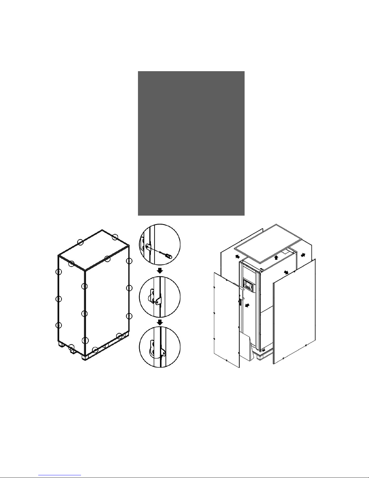
2.3 Unpacking
1. Use a forklift to move the product to installed area. Refer to Figure 2-1. Please make sure the
bearing capacity of forklift is sufficient.
2. Please follow the orders in Figure 2-2 to remove carton and foams.
Figure 2-1
Figure 2-2
Page 8

5
3. Put a ramp in the front of the cabinet and insert small wood into groove. Then, remove two
side panels. Refer to Figure 2-3.
Figure 2-3
4. Remove 4 fixing cabinet plates and loosen leveling feet by rotating them counterclockwise.
Then, move the cabinet from the pallet. Refer to Figure 2-4.
5. To fix the cabinet in position, simply rotate leveling feet clockwise. Refer to Figure 2-5.
Figure 2-4
Figure 2-5
Page 9

6
2.4 Moving the Cabinet
The UPS is fixed on the pallet with 4 fixing cabinet plates. When removing it, pay attention to
the movement of the casters to avoid accidents.
The cabinet can be pushed forward or backward only. Pushing it sideward is not allowed.
When pushing the cabinet, pay attention not to overturn it as the gravity center is high.
1. If you need to move the UPS over a long distance, please use appropriate equipment like a
forklift. Do not use the UPS casters to move over a long distance.
2. After the UPS has been removed from the pallet to ground, we suggest that at least three
people move the UPS to the installation area. One person holds a lateral side of the UPS with
hands, another holds the other lateral side of the UPS with hands, and the other person pushes
the UPS either from the front side or from the back side to the installation area and avoid
tipping the UPS.
3. The casters are designed to move on level ground. Do not move the UPS on an uneven surface.
This might cause damage to the casters. Toppling the UPS could also damage the unit.
4. Ensure that the weight of UPS is within the designated bearing capacity of any handling
equipment.
5. At the bottom of the UPS, the four casters help you to move the UPS to a designated area.
Before you move the UPS, please turn the four leveling feet counterclockwise to raise them off
the ground. This protects the leveling feet from damage when moving the UPS. Refer to Figure
2-6.
Figure 2-6
Page 10

7
2.5 Types of UPS Cabinet
There are two series of UPS cabinets, standard and extended for different requirements.
The standard cabinets have the battery modules inside and they can work as a stand-alone UPS or
be connected to battery externally.
The extended cabinets don’t have the battery module compartments. The battery has to be
connected externally.
Please consider the external battery space and wiring gauge for installation.
Standard Series
Extended Series
Photo
Cabinet
Height
30U
42U
30U
30U
42U
42U
Switch
Unit
1 1 1 1 1
1
STS 1 1 1 1 1 1
Max.
Power
Module
3 4 4 6 8
10
Battery
Module
12
20
N/A
N/A
N/A
N/A
Page 11
8
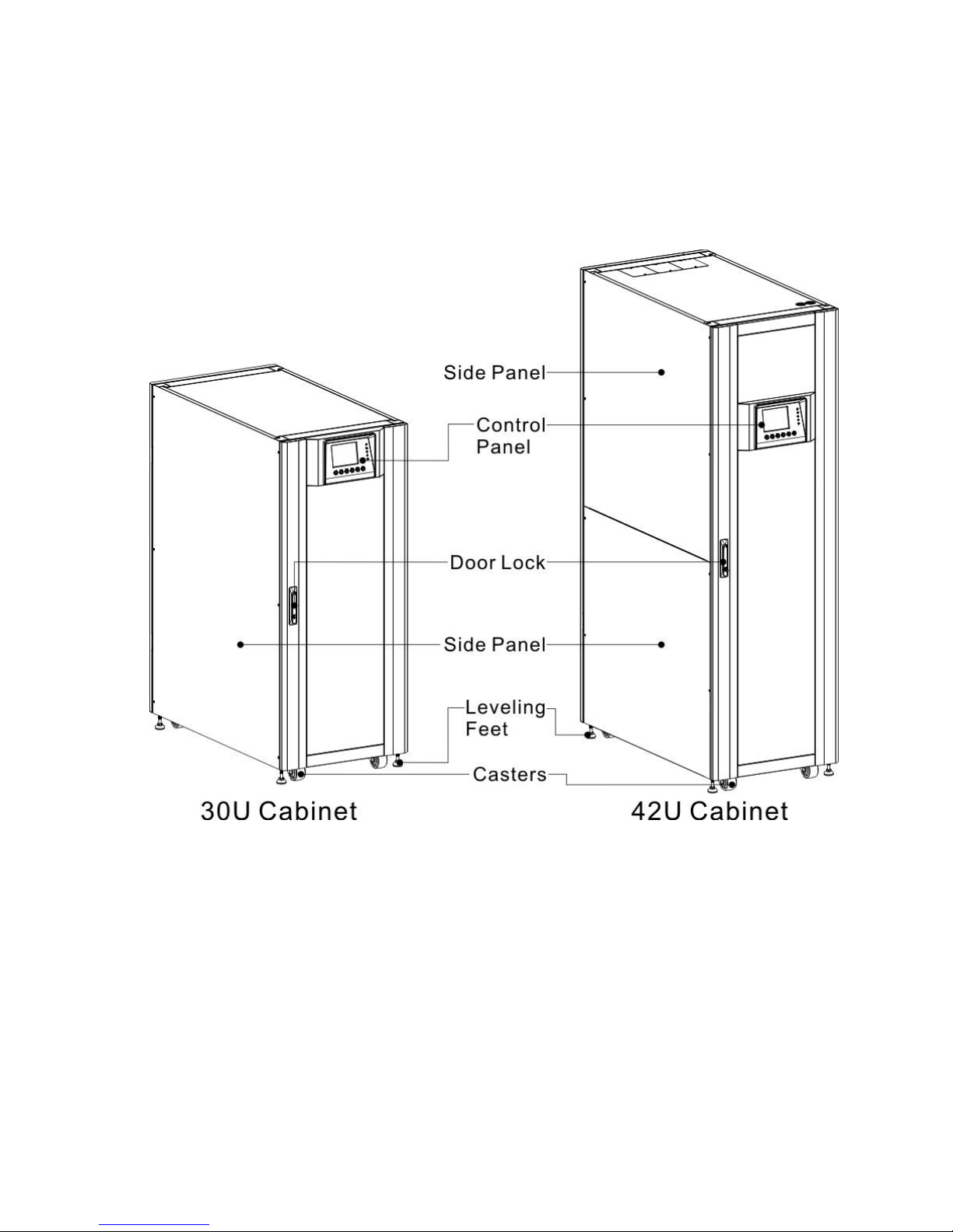
2.6 Exterior
In the front of the UPS, there are control interface (LCD Panel) and door lock.
The side panels are lockable. The casters at the bottom of the UPS cabinet can be used to move
over short distances. There are four leveling feet to fix and stabilize the UPS cabinet on the ground.
Refer to Figure 2-7.
Inside the cabinet, there are Breakers, STS Module, Power Module slots and Battery module slots
(Battery Module Slots is only for standard series). All wiring terminal blocks are located in the back
of cabinet.
Figure 2-7 Exterior
Page 12
9
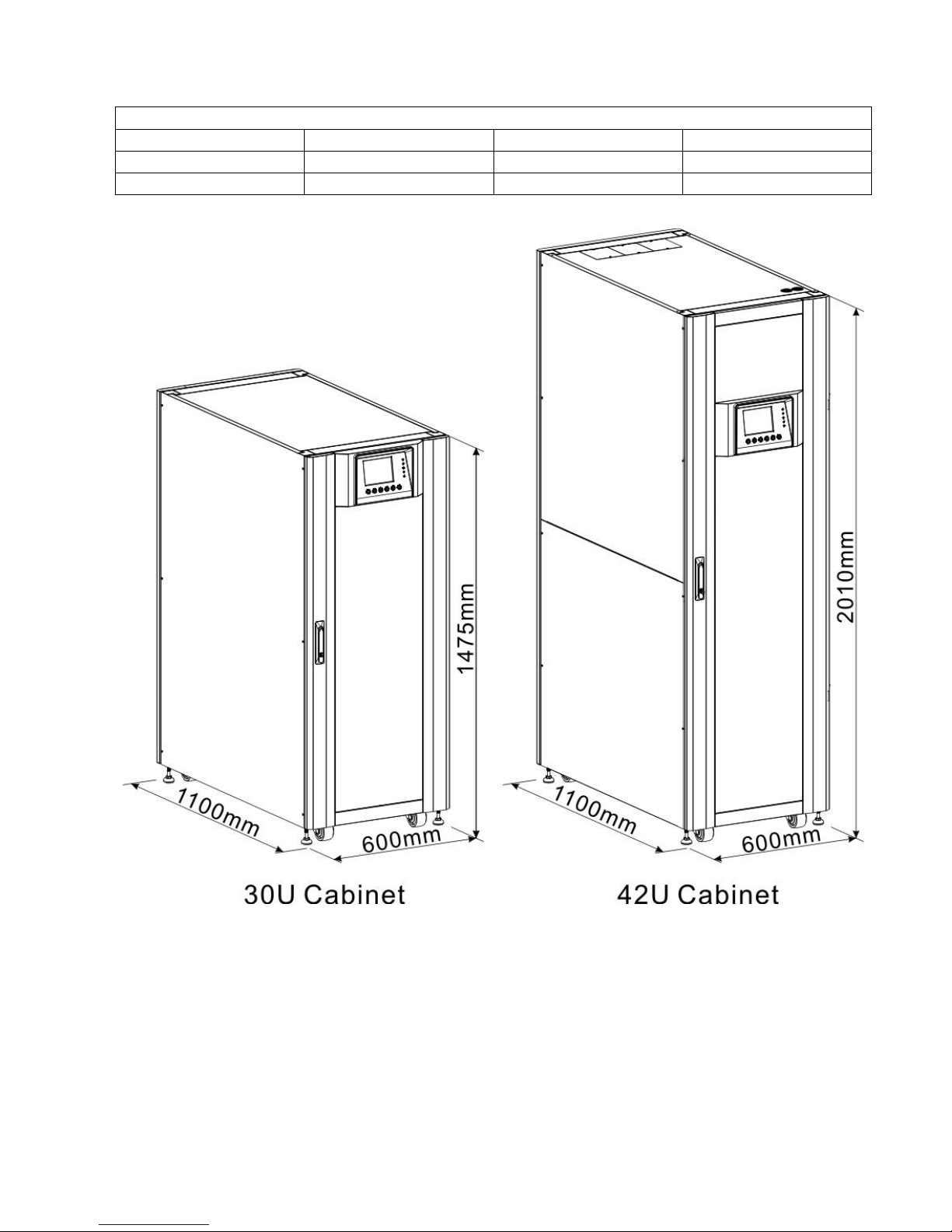
2.6.1 Mechanical Data
Dimensions
UPS cabinet
Width
Depth
Height
30U
600mm
1100m
1475mm
42U
600mm
1100m
2010mm
Figure 2-8 Dimensions
Page 13

10
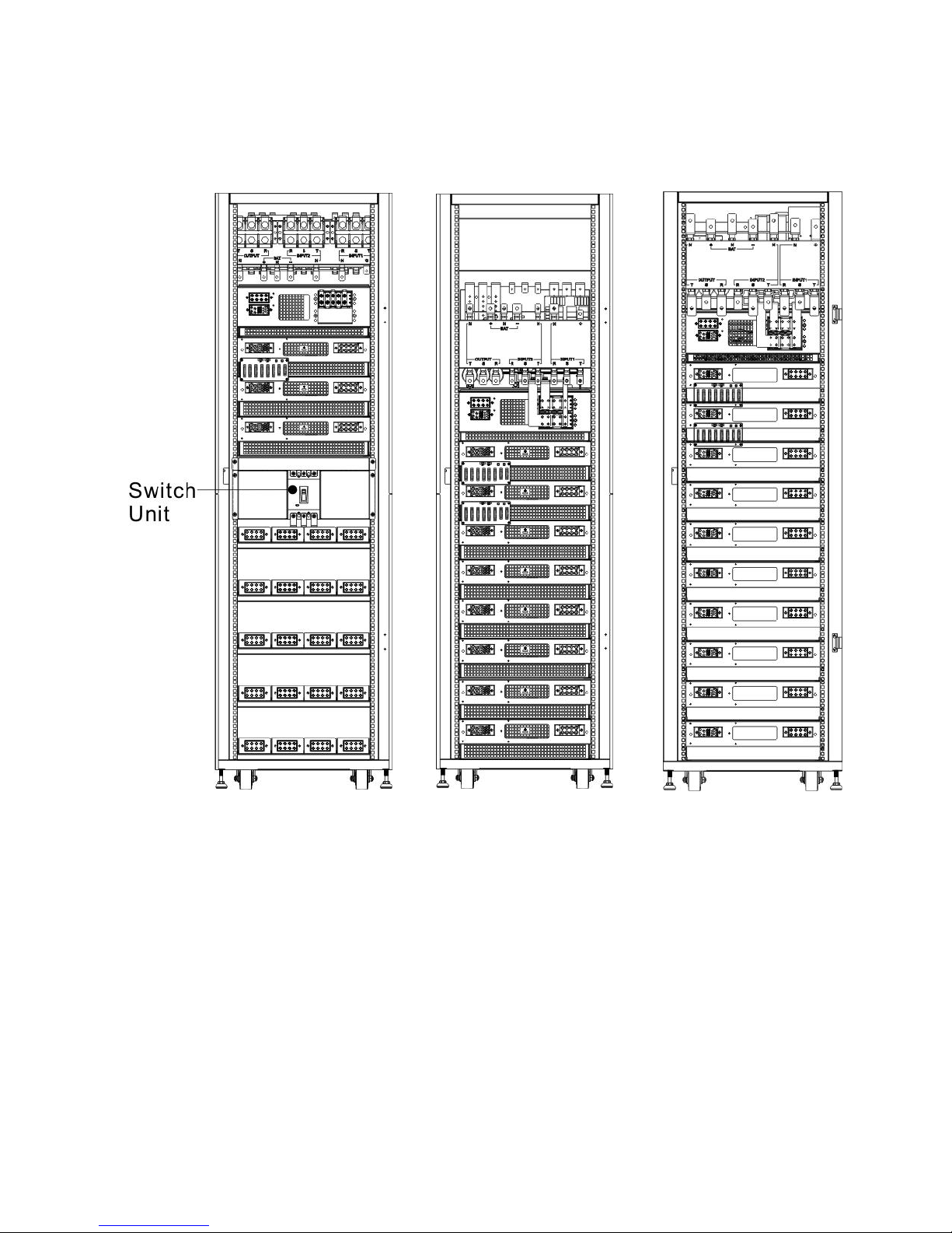
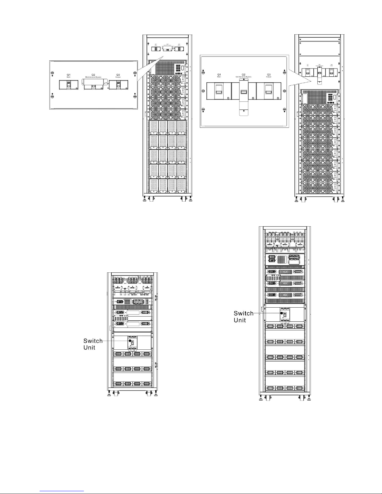
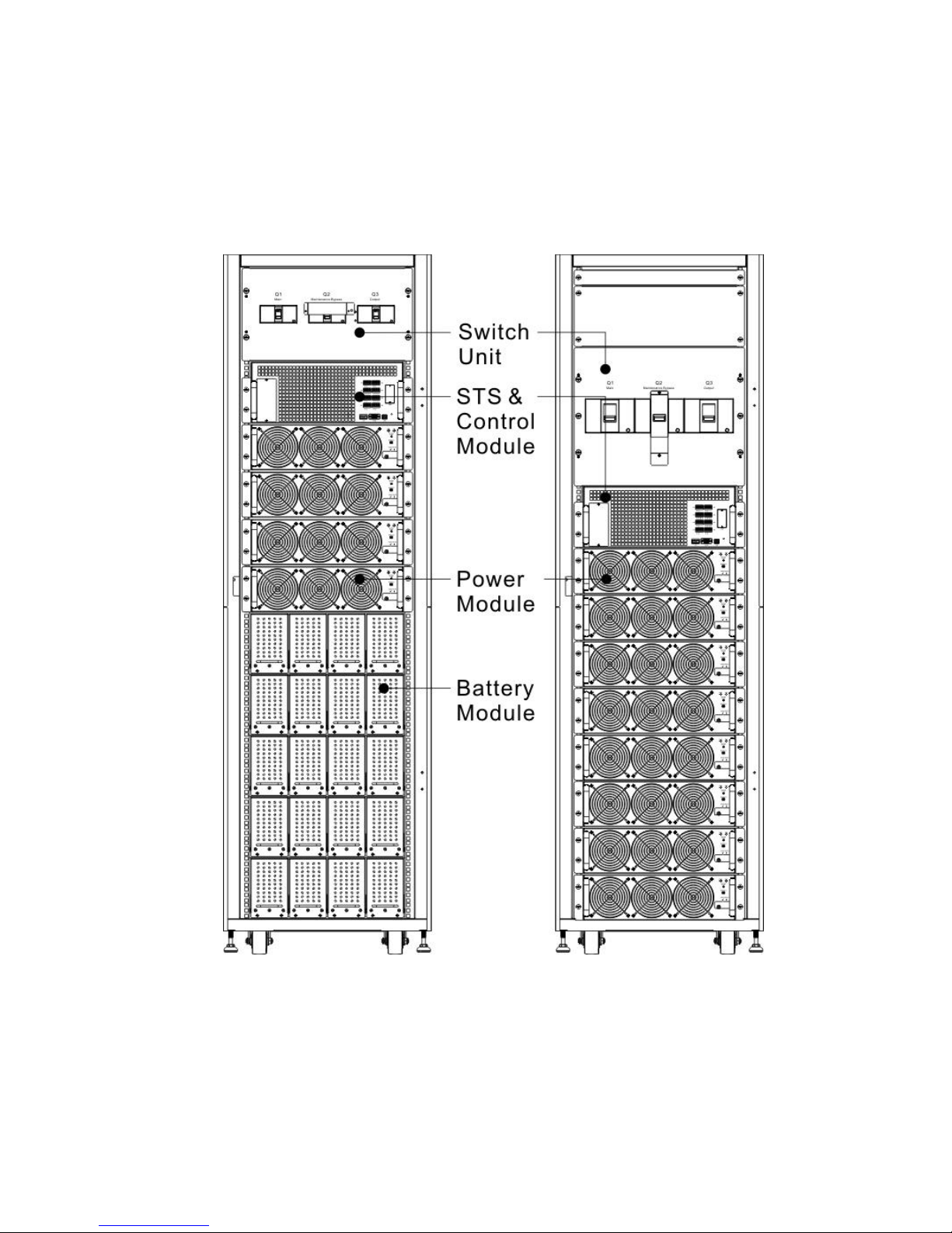
2.6.2 Front View
Unlock and open the front door and you will see the Main Breaker (Q1), Maintenance Breaker (Q2),
Output Breaker (Q3), STS Module, Power Module slots and Battery Module slots (Battery Module
Slots is only for standard series).
The cabinet of 300K Model has Maintenance Bypass Switch Only.
Standard Series Extended Series
1. Switch Unit
2. STS Module
3. Power Module
4. Battery Module
Page 14
11
2.6.3 Rear View
Unlock and open the rear door and you will see the rear panel of UPS. There is a Battery Breaker
for internal battery modules in the standard series, but there isn’t any in the extended series.
Standard Series
Extended Series
Figure 2-10 Rear View
2.7 Internal Mechanisms
2.7.1.1 Breakers
After opening the front door, there are three breakers, Main Breaker (Q1), Maintenance Breaker
(Q2) and Output Breaker (Q3).
For the standard series, there is a battery breaker for internal battery modules. You can see it
when you open the rear door.
Page 15
12
Standard Series (42U Front)
Extended Series (42U Front)
Figure 2-11 Front Breakers
Standard Series (30U Rear)
Standard Series (42U Rear)
Figure 2-12 Rear Breaker
Page 16

13
2.7.1.2 Maintenance Bypass Switch
After opening the front door, there is one Maintenance Bypass Switch in the 300K cabinet.
Figure 2-12.1 Maintenance Bypass Switch
Page 17

14
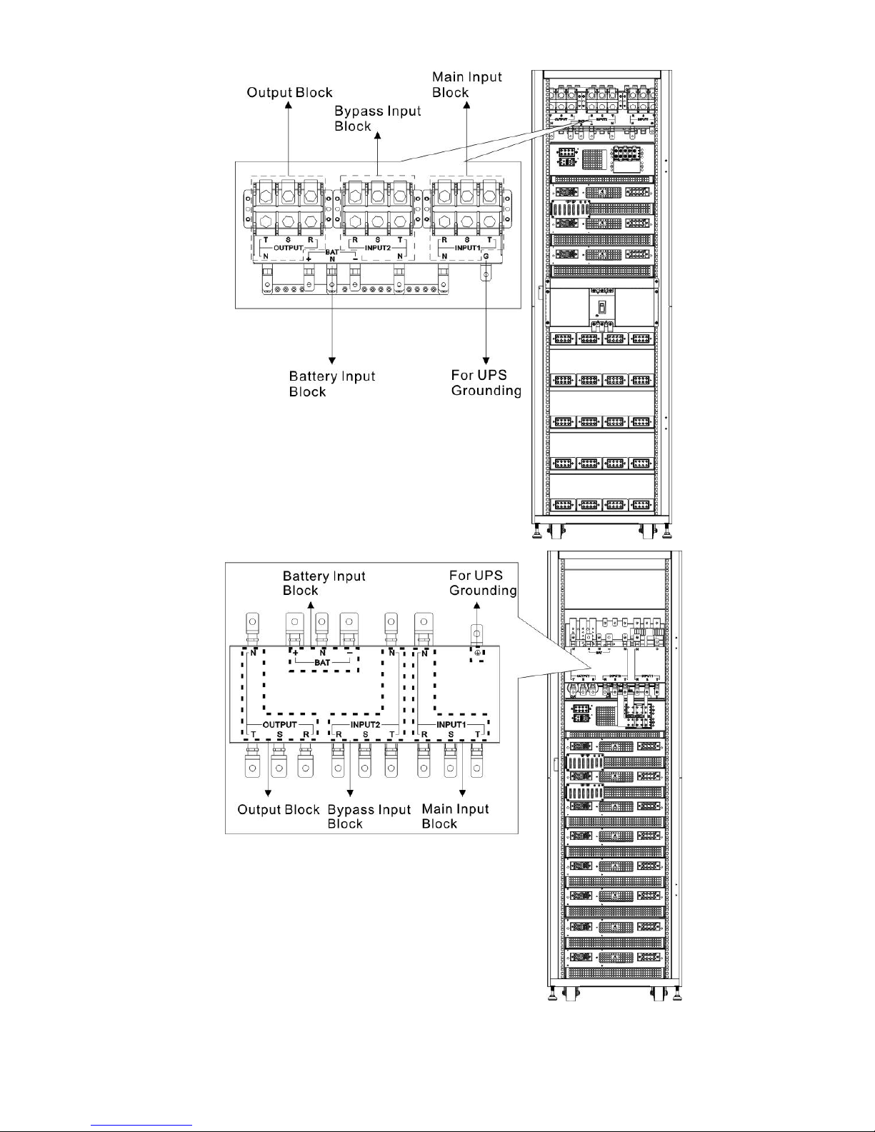
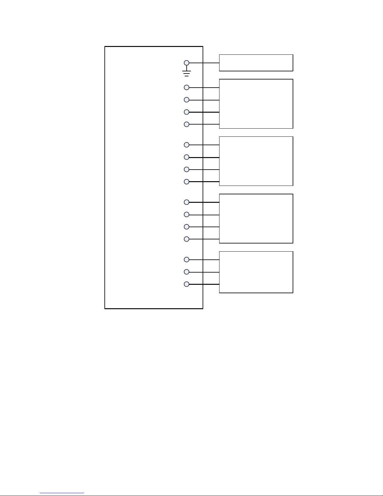
2.7.2 Wiring Terminal Blocks
Open the UPS’s back doors and you will see the wiring terminal block. For UPS cabinet wiring,
please refer to Figure 2-13.
No.
Item
Function
Description
Output Block
Connects the critical loads
Includes R, S, T and Neutral
terminals.
Bypass Input Block
Connects bypass AC source
Includes R, S, T and Neutral
terminals.
Main Input Block
Connects main AC source
Includes R, S, T and Neutral
terminals.
For UPS Grounding
For UPS grounding
Includes one grounding terminal.
Battery Input Block
Connects an external battery
cabinet
Includes
Positive (+), Negative (-) and
Neutral (N) terminals.
Figure 2-13 Standard Series (30U) Terminal Blocks
Page 18
15
Figure 2-14 Standard Series (42U) Terminal Blocks
Figure 2-15 Extended Series (42U) Terminal Blocks
Page 19

16
2.8 Control Panel
2.8.1 LCD Display
Through the graphic LCD display, the user can easily understand the operation mode of UPS. In
addition, the measurement, parameters, versions of firmware and warnings can be browsed in the
friendly interface. For detailed information, please refer to Chapter 4.
Figure 2-16 Control Panel
2.8.2 LED Indicators
LED
Color
Status
Definition
INPUT
Green
On
Input source is normal.
Flashing
Input source is abnormal.
Off
No input source
BYPASS
Yellow
On
Load on Bypass.
Flashing
Input source is abnormal.
Off
Bypass not operating.
INVERTER
Green
On
Load on inverters.
Off
Inverters not operating.
BATTERY
Red
On
Load on Battery.
Flashing
Low battery
Off
Battery converter is normal and battery is charging.
ALARM
Red
On
UPS fault.
Flashing
UPS alarm.
Off
Normal.
Page 20

17
2.8.3 Function Keys
Control Key
Description
Esc
When it is in Main screen, you can enter menu by pressing ESC
key.
Return to previous screen, when screen is not in Main screen.
Return to previous value in the same row, so you can change it.
For example, when changing 4-digit password, press “Esc” to
allow cursor back to previous digit.
(Up) (Left)
Key for menu page navigation or digit modification.
(Down) (Right)
Key for menu page navigation or digit modification.
Enter
Confirmation of commands, or cursor displacement.
Home
Return to Main screen.
Power On/Off
Turn on UPS or turn off UPS.
Page 21
18
2.9 Introduction of Modules
The design of STS Module, Power Module and Battery Module make maintenance and replacement
quick and easy.
The modular and hot-swappable design of Power Module makes it a highly cost-effective solution
to meet your power requirement. The number of Power Modules installed in the UPS can be based
on the initial needs. Once the power requirement increases, you can easily install more Power
Modules without interrupting the operation of the system.
Figure 2-17 Front View of Module
Page 22
19
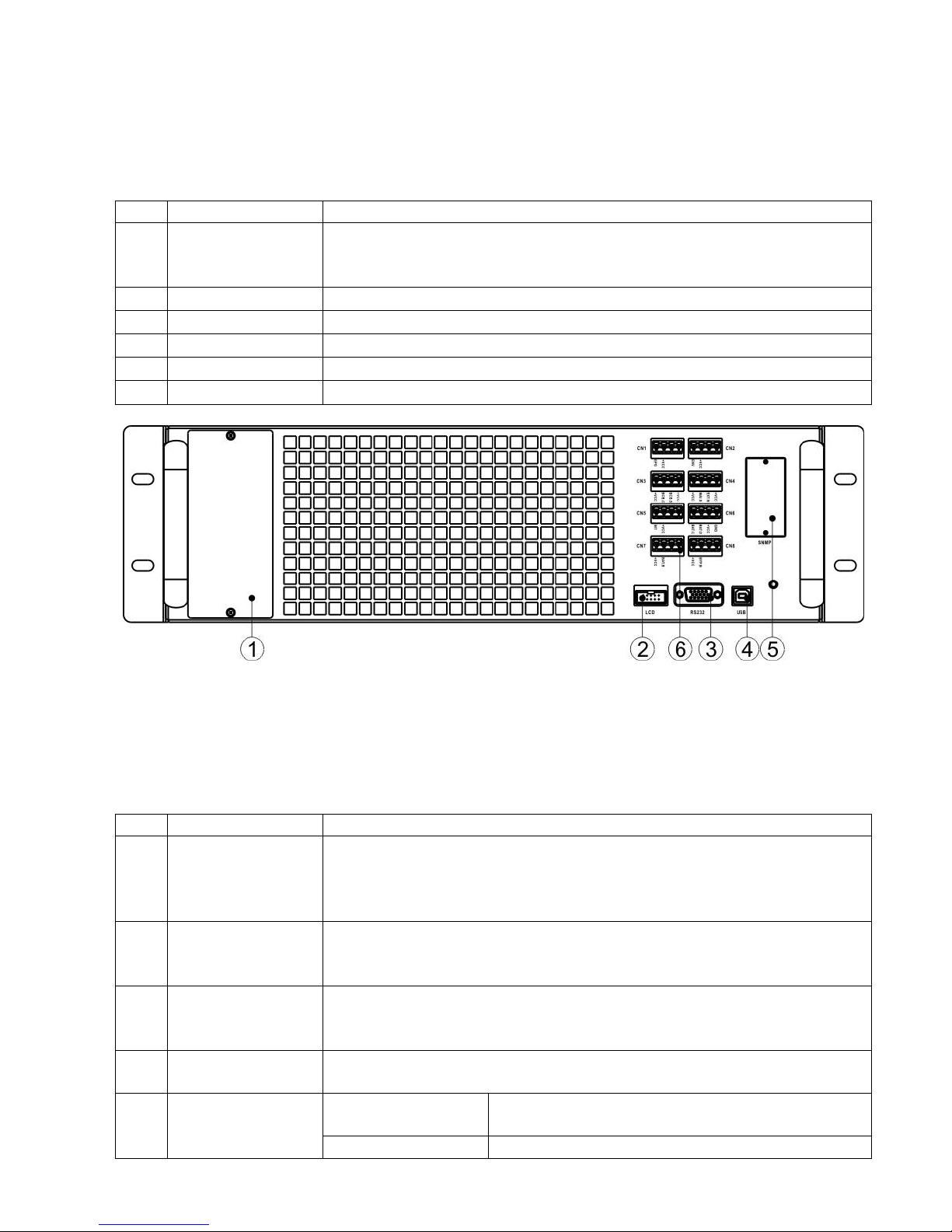
2.9.1 STS Module
The STS Module is installed before leaving factory. It provides the bypass power when UPS is in
Bypass Mode.
In addition to offering bypass power, it includes some communication interfaces. For detailed
information, please refer to Charter 5.
No.
Item
Description
Extra Comm. Slot
This slot can insert an optional card, Extra Comm. card which can
enhance the communication capability of UPS system. It can provide
another SNMP slot and some dry contact ports.
LCD Port
This port connects to Control Panel with a factory installed cable.
RS232 port
Local communication interface.
USB port
Local communication interface.
SNMP Slot
This slot can work with optional cards, SNMP, AS400 or Modbus card.
Dry contact ports
CN1 ~ CN8. For detailed information, please refer to Chapter 5.
Figure 2-18 STS Module
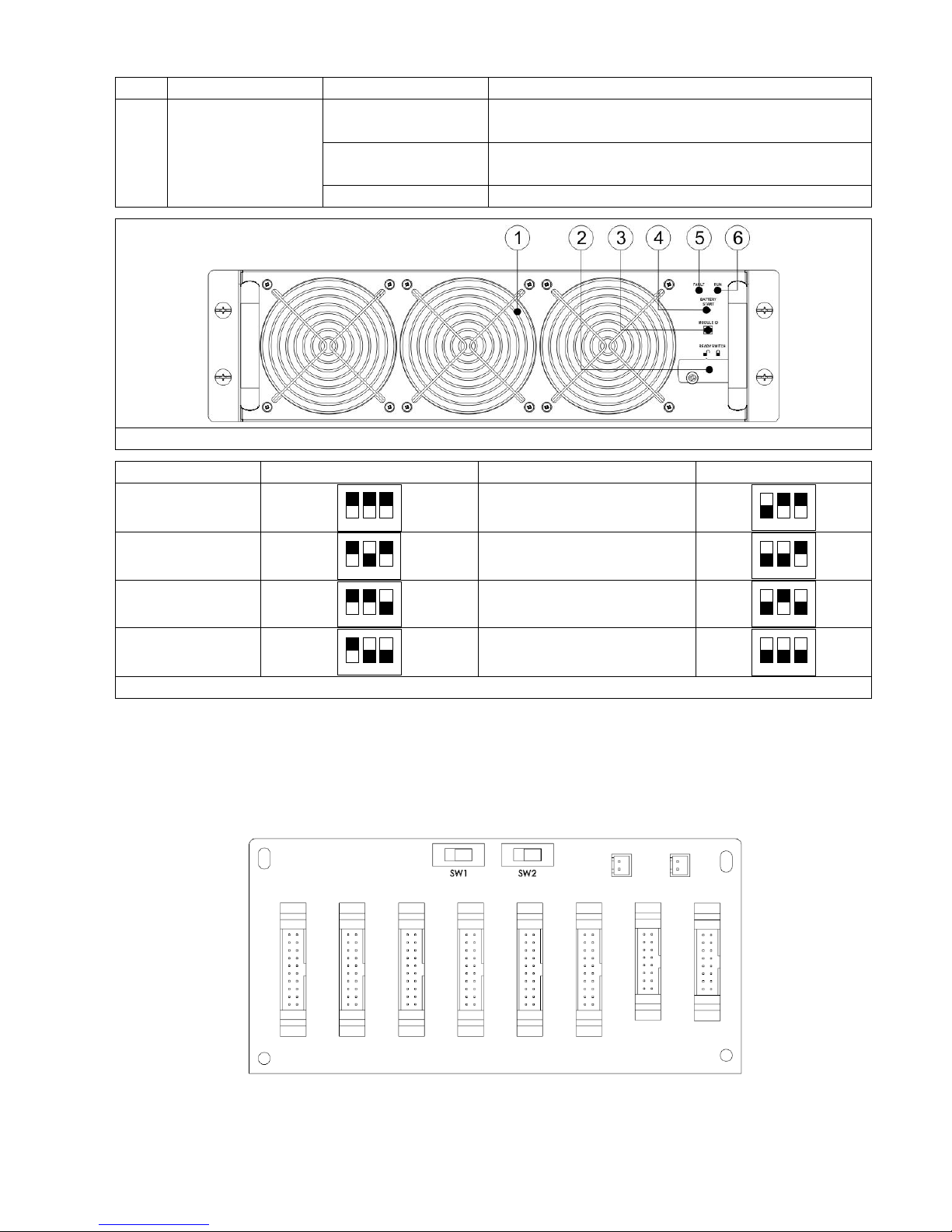
2.9.2 Power Module
Each Power Module is shipped with its own package. It has to be installed during the UPS system
installation.
The capacity of each Power Module is 30kVA/30kW. It includes a power factor correction rectifier,
a battery charger, an inverter and control circuit.
No.
Item
Description
Fan
The Power Module uses forced convection cooling by these fans.
Cooling air enters the module through ventilation grills and exhausted
through grills located in the rear of the module. Please do not block
the ventilation area.
Ready Switch
Unlock it before removing the Power Module.
Lock it when the Power Module is well installed. Then the Power
Module can start to work.
DIP Switches
There are three DIP switches for Power Module address setting. In
the same cabinet, each Power Module ID MUST be exclusive. The
setting method is shown in Table 2-1.
Battery Start
Button
When AC input is not existing, use this button to start battery power
for UPS.
FAULT LED
ON
The Power Module is in fault condition or the
Ready Switch is unlocked.
ON/OFF 0.5 sec
The Power Module IDs conflict.
Page 23
20
ON/OFF 0.15 sec
The STS Module is not found.
RUN LED
ON
The Power Module normally works as a slave
module.
ON/OFF 0.5 sec
The Power Module normally works as a master
module.
ON/OFF 0.15 sec
The CAN Bus communication doesn’t work.
Figure 2-19 Power Module
Module Address
DIP SWITCH
Module Address
DIP SWITCH
0
1 2 3
1
1 2 3
2
1 2 3
3
1 2 3
4
1 2 3
5
1 2 3
6
1 2 3
7
1 2 3
Table 2-1 DIP switch setting and Module Address
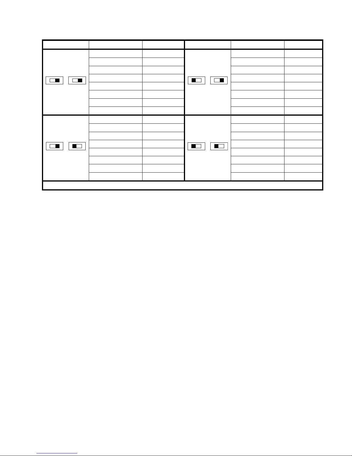
Power Module ID Assignment
According to the Module Address and the position of SW1 and SW2, the Power Module’s ID is
assigned. The Module ID is shown in Table 2-2.
These two switches, SW1 & SW2 are mounted in the Parallel board which is located at the back of
UPS cabinet. Refer to Figure 2-20.
Figure 2-20 Parallel Board
The SW1 and SW2 position have been well installed before leaving factory. It’s not necessary to
change it for single UPS system application. But for Parallel UPS system application, please follow
Page 24
21
the instructions in Chapter 9 “ UPS Installation for Parallel Rack System “ to adjust SW2.
SW1 & SW2
Module Address
Module ID
SW1 & SW2
Module Address
Module ID
SW1 SW2
0
0
SW1 SW2
0 9 1 1 1
10
2 2 2
11 3 3 3 12 4 4 4 13 5 5 5 14 6 6 6 15
7 7 7
16
SW1 SW2
0
18
SW1 SW2
0
27 1 19 1 28 2 20 2 29
3
21 3 30
4
22 4 31 5 23 5 32
6
24 6 33
7
25 7 34
Table 2-2 Module ID Assignment
Page 25

22
Page 26
23
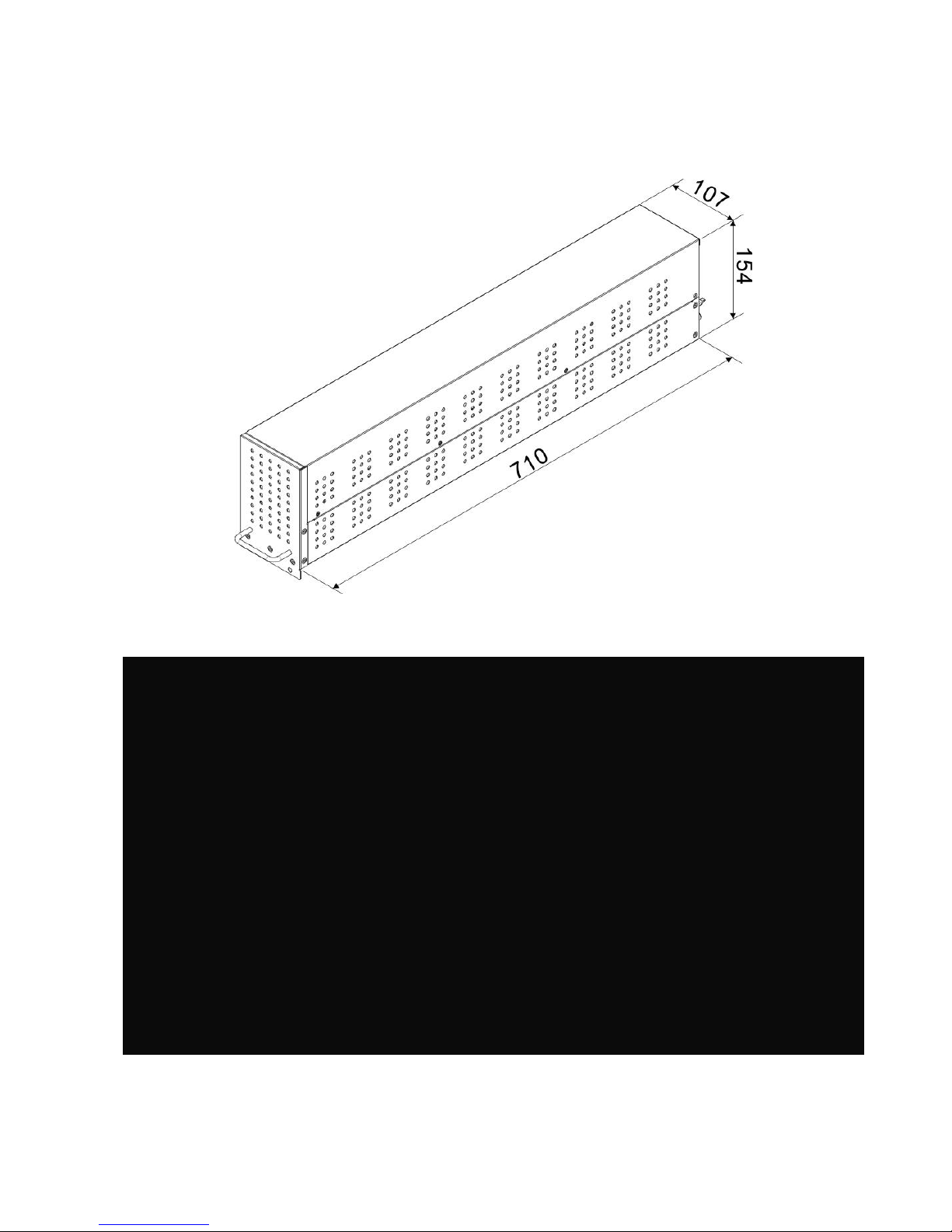
2.9.3 Battery Module
The Battery Module is shipped with its own package. The inside batteries can be installed at
factory or installed by the end user. A Battery Module contains 10 pcs of 12V/9Ah batteries at
maximum.
Figure 2-21 Battery Module
Figure 2-22 Internal Wiring of Battery Module
Page 27
24
2.10 Power Cable
Please follow the local wiring regulations. Follow environmental conditions and
refer to IEC60950-1.
2.10.1 AC input and output maximum current and power cable configuration.
For standard model in 30U cabinet (Battery inside)
Model
30KVA
60KVA
90KVA
Current (A)
55
110
165
Power cable (mm2)
10
35
70
Fixation torque force (lb-in)
20
20
20
For standard model in 42U cabinet (Battery inside)
Model
30KVA
60KVA
90KVA
120KVA
Current (A)
55
110
165
220
Power cable (mm2)
10
35
70
95
Fixation torque force (lb-in)
20
20
20
20
For extended series in 30U & 42U cabinet
Model
30KVA
60KVA
90KVA
120KVA
150KVA
Current (A)
55
110
165
220
275
Power cable (mm2)
10
35
70
95
150
Fixation torque force (lb-in)
20
20
20
20
20
Model
180KVA
210KVA
240KVA
270KVA
300KVA
Current (A)
330
385
440
495
550
Power cable (mm2)
240
300
300
120*2
150*2
Fixation torque force (lb-in)
20
20
20
20
20
Notice: Installer has to consider the max. current and wiring gauge when considering future
extension.
2.10.2 DC input maximum current and power cable configuration.
For standard series in 30U cabinet (Battery inside)
Model
30KVA
60KVA
90KVA
Current (A)
100
200
300
Power cable (mm2)
25
95
150
Fixation torque force (lb-in)
20
20
20
Warning:
1. When Load is less than 30KVA, at least two layers of battery modules (8 modules) have to be
installed.
2. When Load is between 30KVA and 60KVA, three layers of battery modules (12 modules) have
to be installed in total.
3. When Load is larger than 60KVA, the external battery cabinet must be installed.
4. The same type of battery has to be used, if the battery is in parallel application.
Page 28

25
For standard series in 42U cabinet (Battery inside)
Model
30KVA
60KVA
90KVA
120KVA
Current (A)
100
200
300
400
Power cable (mm2)
25
95
150
240
Fixation torque force (lb-in)
20
20
20
20
Warning:
1. When Load is less than 30KVA, at least two layers of battery modules (8 modules) have to be
installed.
2. When Load is between 30KVA and 60KVA, at least three layers of battery modules (12 modules)
have to be installed.
3. When Load is between 60KVA and 90KVA, at least five layers of battery modules (20 modules)
have to be installed.
4. When Load is larger than 90KVA, the external battery cabinet must be installed.
5. The same type of battery has to be used, if the battery is in parallel application.
For extended series in 30U & 42U cabinet
Model
30KVA
60KVA
90KVA
120KVA
150KVA
Current (A)
100
200
300
400
500
Power cable (mm2)
25
95
150
240
120 x 2
Fixation torque force (lb-in)
20
20
20
20
20
Model
180KVA
210KVA
240KVA
270KVA
300KVA
Current (A)
600
700
800
900
1000
Power cable (mm2)
150 x 2
240 x 2
240*2
300*2
185*3
Fixation torque force (lb-in)
20
20
20
20
20
2.11 Wiring
WARNING:
Before connecting any wire, make sure the AC input and battery power is completely cut off.
Make sure the breakers, Main Breaker (Q1), Maintenance Breaker (Q2), Output Breaker (Q3)
and battery breaker are all in the OFF position.
Make sure the Maintenance Bypass Switch is in UPS position.
In order to have good heat dissipation, the power cables MUST come into the cabinet from top
of the cabinet. Or the cables will block the cooling ventilation and make the over temperature
failure.
Page 29
26
2.11.1 Installation Drawing
UPS
G To User Safety ground
Input1
R
S
T
N
To Main SUPPLY
(Power Cables)
Input2
R
S
T
N
To Bypass SUPPLY
(Power Cables)
Output
R
S
T
N
To Critical Load
(Power Cables)
BAT
+
N
-
To External BATTERY
(Power Cables)
Figure 2-23 UPS Cabinet Wiring
2.11.2 AC source connection
For Single input application, connect Input1 to the AC power source and use 3 short wires to
connect Input1 and Input2.
For Dual input application, connect input1 to the Main AC power source and connect input2 to
the Bypass power source.
The sequence of three phase, R, S and T must be connected accordingly. The wrong sequence will
alarm a warning when the UPS is powered.
The N must be connected firmly. A warning message will be indicated, if the N is not connected
well.
There is no Breaker between Input2 and STS Module, the STS module is waked up when Input2 is
powered, though the Q1 Breaker is OFF.
For the 300K cabinet, there is no input breaker nor output breaker. These breakers have to be
installed externally.
Page 30
27
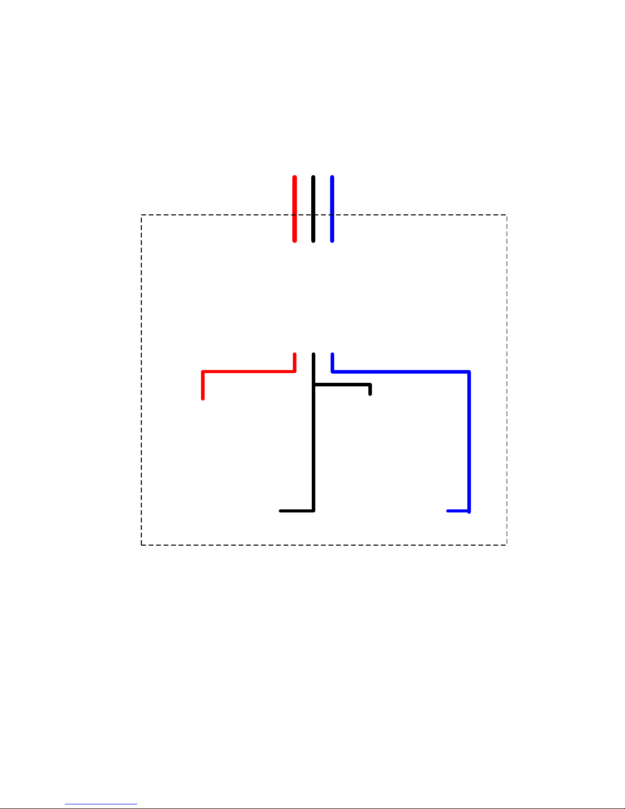
2.11.3 External Battery Cabinet Connection
External Battery
Cabinet
+ Battery - Battery
Figure 2-24 External Battery Cabinet Wiring
After the battery is completely installed, be sure to set up nominal battery voltage, battery capacity
and maximum charging current in LCD setting. Otherwise, if battery setting is different from actual
installation, the UPS will keep warning. Please refer to section 4.2.6.3 and Table 4-9 for the
details.
Page 31

28
2.12 Power Module Installation
The weight of Power Module is over 30Kg so at least two persons are required for
handling.
2.12.1 Insert the Power Module
(1.) Adjust the DIP switch positions to set the different Module Address. Refer to Table 2-1.
(2.) Place the ready switch on the front panel of the module to the “ ” position (i.e., in unready
state).
(3.) Insert the Power Module into an unoccupied slot by two persons.
Page 32

29
(4.) Secure the Power Module to the cabinet by fixing the screws at the front panel of the Power
Module.
(5.) Move the ready switch to the “ ” position (i.e., in ready state).
2.12.2 Remove the Power Module
Before removing any Power Module, make sure the remaining Power Modules
can support the critical loads.
At least one Power Module MUST stay in the UPS cabinet except the UPS
system is operating in Maintenance Bypass Mode.
(1.) Turn the ready switch to the “ ” position.
(2.) The Power Module FAULT LED (RED) indicator is lit to indicate the Power Module output is off
and disconnected from UPS system.
(3.) Use a screwdriver to remove the four screws from fixing holes.
(4.) Two people pull out together and remove the Power Module from its slot.
Page 33

30
2.13 Battery Module Installation
The weight of Battery Module is heavy so at least two persons are required for
handling.
Before performing the Battery Module installation/ replacement, make sure the
Battery Breaker is in the OFF position.
2.13.1 Insert the Battery Module (Only Standard Series Cabinet)
(1.) Open the UPS’s front door and remove the panel of battery module slot.
(2.) There are 4 rails for inserting the Battery Modules in the same layer. Four Battery Modules
MUST be installed to form a set of Battery.
(3.) Regarding the maximum load of power modules, please refer to section 2.10.2 to install the
required Battery Modules.
(4.) Secure the Battery Module to the cabinet by fixing the screws of the Battery Module.
Page 34

31
3. Operation Mode and UPS Operation
3.1 Block diagram of UPS
Wiring diagram for dual inputs (90KVA~210KVA)
Wiring diagram for dual inputs (300KVA)
Figure 3-1
Page 35

32
Wiring diagram for single input (90KVA~210KVA)
Wiring diagram for single input (300KVA)
Figure 3-2
3.2 Operation Mode
This modular UPS is a three-phase, four wire on-line, double-conversion and reverse-transfer UPS
that permits operation in the following modes:
Standby Mode
Line Mode
Battery Mode
Bypass Mode
ECO Mode
Page 36

33
Shutdown Mode
Maintenance Bypass Mode (manual bypass)
3.2.1 Standby Mode
Upon connecting to utility input power, the UPS is in Standby mode before UPS is turned on (if
BYPASS enable setting is Disabled), and charger function will be active when the battery is present.
The load is not powered under this mode.
Figure 3-3 : Standby Mode Diagram
Page 37

34
3.2.2 Line Mode
In Line Mode, the rectifier derives power from the utility power and supplies DC power to the
inverter and the charger charges the battery. The inverter filters the DC power and converts it into
pure and stable AC power to the load.
Figure 3-4 : Line Mode Diagram
Page 38

35
3.2.3 Battery Mode
The UPS automatically transfers to Battery mode if the utility power fails. There is no interruption
in power to the critical load upon failure.
In battery mode, the rectifier derives power from the battery and supplies DC power to the
inverter. The inverter filters the DC power and converts it into pure and stable AC power to the
load.
Figure 3-5 : Battery Mode Diagram
Page 39

36
3.2.4 Bypass Mode
Upon connecting to utility input power, the UPS is in Bypass mode before UPS is turned on (if
BYPASS enable setting is Enabled), and charger function will be active when battery is present.
After UPS has been turned on, if the UPS encounters abnormal situations (over-temperature,
overload …, etc.), the static transfer switch will perform as a transference of the load from the
inverter to the bypass source with no interruption. If the transference is caused by a recoverable
reason, the UPS will turn back to line mode when abnormal situation is solved.
Figure 3-6 : Bypass Mode Diagram
Page 40

37
3.2.5 ECO Mode
The ECO Mode is enabled through the setting menu of LCD panel. In ECO mode, the load is
powered by bypass when the bypass voltage and frequency are within the acceptable ranges. If
the bypass is out of range, the UPS will transfer the power source of load from bypass to inverter.
In order to shorten the transfer time, the rectifier and inverter are working when the UPS is in ECO
mode.
Figure 3-7 : ECO Mode Diagram
Page 41

38
3.2.6 Shutdown Mode
When the UPS is in the off state and the utility power source is absent, the UPS will enter into
shutdown mode.
Or when the UPS has discharged the battery to the cut-off level, the UPS will enter into shutdown
mode as well.
When the UPS enters this mode, it is going to shut off the control power of UPS. The rectifier,
charger and inverter are all in off state.
Figure 3-8 : Shutdown Mode Diagram
Page 42

39
3.2.7 Maintenance bypass Mode
A manual bypass switch is available to ensure continuity of supply to the critical load when the UPS
becomes unavailable e.g. during a maintenance procedure. Before entering the maintenance
bypass mode, make sure the bypass power source is normal.
Figure 3-9 : Maintenance Bypass Mode Diagram
Page 43

40
3.3 UPS Operation
Do not start the UPS until the installation is completed.
Make sure the wiring is correct and the power cables are fixed firmly.
Make sure the Power Modules’ address have been configured. Refer to section
2.9.2 Power Module
Make sure the ready switch on the Power Module has been moved to the
“Locked” position.
Make sure all the breakers are switch OFF.
3.3.1 AC Startup
Ensure to follow this procedure when turning on the UPS from a fully powered-down condition.
The operating procedures are as follows:
Step 1: Refer to “Chapter 2 Installation” to connect the power cables and install the Power
Modules and the battery required for the UPS system.
Step 2: Switch ON the battery breaker.
Step 3: Switch ON the external power switch to power the UPS. The STS module starts running
and the LCD panel is displayed.
Page 44

41
Step 4: Switch ON the input breaker (Q1). The UPS will enter into Standby Mode, if the setting of
Bypass mode is disabled.
Or the UPS will enter into Bypass Mode, if the setting of Bypass mode is enabled.
Step 5: Make sure there is no warning or fault event happening. If yes, please refer to Chapter 6
Troubleshooting to solve it.
Page 45

42
Step 6: Press Power ON/OFF button for two seconds to enter into Line Mode as shown below.
After turning on, UPS will do self-test and start Inveter up. UPS will be transferred to Line mode
when all power modules are ready.
Step 7: Switch ON the output breaker (Q3). AC startup procedure is complete.
Page 46

43
3.3.2 Cold Start Startup
Step 1: Switch ON the battery Breaker.
Step 2: Press the “Battery Start” button on any one of Power Modules to start up the control
power of all Power modules and STS moodule as shown below.
Battery Start Button
Step 3: After pressing the “Battery Start” button, UPS will enter into Standby mode. Refer to the
diagram below for LCD display.
Step 4: Before UPS enters into shutdown mode, please press “Power On/Off” button for 2 second
immediately as shown in the diagram below.
Page 47

44
Step 5: Then, UPS will enter Battery Mode as shown in the diagram below.
Step 6: Switch ON the output breaker (Q3). Cold start startup procedure is complete.
3.3.3 Maintenance Bypass Operation
Follow the instruction to transfer to Maintenance Bypass and UPS protection as below.
3.3.3.1 Transfer to maintenance bypass
90KVA~210KVA.
300KVA
Step 1:
Remove the mechanical lock plate of
Maintenance Bypass Breaker.
Remove the mechanical lock plate of
Maintenance Bypass Switch.
Step 2
Make sure the UPS operates in Bypass
mode as shown below.
Make sure the UPS operates in Bypass
mode as shown below.
Page 48

45
Step 3
Switch ON the Maintenance Bypass
Breaker as shown below.
Switch the handle toward upside as
shown below.
Step 4
Switch OFF the Main Breaker (Q1) and
Output Breaker (Q3) as shown below.
It is possible to change the STS module,
Power Module.
Step 5
It is possible to change the STS
module, Power Module and Battery
Module.
3.3.3.2 Transfer to UPS Protection
90KVA~210KVA.
300KVA
Step 1
Make sure the maintenance is
complete. The Power Modules and STS
module have been installed well.
Make sure the maintenance is
complete. The Power Modules and STS
module have been installed well.
Page 49

46
Step 2
Switch ON the Main Breaker (Q1) and
Output Breaker (Q3) as shown below.
Please enter LCD SETUP MENU and
choose “SYSTEM” to ensure that the
“Bypass mode” is enabled. If the
“Bypass mode” is disabled, you have to
set it enabled. Then, exit the SETUP
menu and check if the UPS operates in
bypass mode.
Step 3
Please enter LCD SETUP MENU and
choose “SYSTEM” to ensure that the
“Bypass mode” is enabled. If the
“Bypass mode” is disabled, you have
to set it enabled. Then, exit the SETUP
menu and check if the UPS operates in
bypass mode.
Switch the handle toward downside as
shown below.
Page 50

47
Step 4
Turn off Maintenance Bypass Breaker
as shown below.
Lock back the mechanical lock plate as
shown below.
Step 5
Lock back the mechanical lock plate as
shown below.
3.3.4 Turn off Operation
3.3.4.1 Bypass Mode/ Standby Mode Turn Off Operation
When the UPS neither is turned on nor turned off, the UPS operates in the Standby Mode or Bypass
Mode. It depends on the “Bypass Mode” Setting.
The LCD diagrams are shown below.
Bypass Mode Setting is Disabled
Bypass Mode Setting is Enabled
Step 1: Switch OFF the Main Breaker. The LCD diagrams are shown below.
Bypass Mode Setting is Disabled
Page 51

48
UPS enters Shutdown Mode.
It is normal the Un-Connection is shown when
Power Modules have shut off their control
power.
Bypass Mode Setting is Enabled
UPS stay in Bypass mode and No AC input is indicated.
Step 2: Switch OFF the external power switch to disconnect the AC power to the UPS. Wait until
the LCD is OFF.
Step 3: Switch OFF the battery breaker, if the UPS will disconnect the AC power for a long time.
3.3.4.2 Line Mode Turn Off Operation
The LCD diagrams are shown below when the UPS operates in the Line Mode.
Page 52

49
Step 1: Press “Power On/Off” button for 2 second to turn off the UPS. Or use the
Menu-Control-System Turn Off to turn off the UPS.
After turning off, the UPS will tranfer to Standby Mode or Bypass Mode. It depends on the “Bypass
Mode” Setting.
Next, follow the Bypass Mode/ Standby Mode Turn Off Operation procedure.
3.3.4.3 Battery Mode Turn Off Operation
The LCD diagram is shown below when the UPS operates in the Battery Mode.
Page 53

50
Step 1: Press “Power On/Off” button for 2 second to turn off the UPS. Or use the
Menu-Control-System Turn Off to turn off the UPS.
After turning off, the UPS will tranfer to Standby Mode.
Next, follow the Bypass Mode/ Standby Mode Turn Off Operation procedure.
Page 54

51
4. Control Panel and Display Description
4.1 Introduction
This control panel and display description are located on the front door of the UPS. It is the USER
control, monitoring of all measured parameters, UPS and battery status and alarms. The control
panel and display description are divided into four functional areas: (1) LCD display, (2) LED
indications, (3) Control keys, (4) Audio Alarm, as shown in Figure 4-1.
Figure 4-1 Control panel
(1) LCD display: Graphic display and all measured parameters.
(2) LED indications. Refer to Table 4-1.
(3) Control keys. Refer to Table 4-2.
(4) Audible Alarm. Refer to table 4-3.
Table 4-1: LED indications
LED
Color
Status
Definition
INPUT
Green
On
Input source is normal.
Flashing
Input source is abnormal.
Off
No input source
BYPASS
Yellow
On
Load on Bypass.
Flashing
Input source is abnormal.
Off
Bypass not operating.
INVERTER
Green
On
Load on inverters.
Off
Inverters not operating.
BATTERY
Red
On
Load on Battery.
Flashing
Low battery
Off
Battery converter is normal and battery is charging.
ALARM
Red
On
UPS fault.
Flashing
UPS alarm.
Off
Normal.
Page 55

52
Table 4-2: Function Keys
Control Key
Description
Esc
When screen is in Main screen, it will enter into main menu by
pressing ESC key.
Return to previous screen, when screen is not in Main screen.
Return to previous value in the same row, so you can change it.
For example, when changing 4-digit password, press “Esc” to
allow cursor back to previous digit.
(Up) (Left)
Key for menu page navigation or digit modification.
(Down) (Right)
Key for menu page navigation or digit modification.
Enter
Confirmation of commands, or cursor displacement.
Home
Return to Main screen.
Power On/Off
Turn on UPS or Turn off UPS.
Table 4-3: Audible Alarm
Audio Type
Description
Power on/off
Buzzer sounds two seconds.
Battery mode
Buzzer sounds every 2 seconds.
Low battery
Buzzer sounds every half seconds.
UPS alarm
Buzzer sounds every 1 second.
UPS fault
Buzzer continuously sounds.
4.2 Screen Description
4.2.1 Start Screen
Upon starting, the UPS executes self-test. The initial screen displays and remains still in
approximately 5 seconds as shown in Figure 4-2.
Figure 4-2 Initial screen
4.2.2 Main Screen
After initialization, the main screen will display as Figure 4-3. Main screen is divided into five parts.
(1) UPS Mode: Current Operation Mode.
(2) UPS Flow Chart: Current flow chart and measurement data.
(3) Menu: Press ESC button to enter Menu screen.
(4) UPS model name with power rating. If the power rating followed with (R) means the UPS
system has redundant configuration.
Page 56

53
(5) Date and Time.
Figure 4-3 Main screen
4.2.3 MENU Screen
In the Main Screen, press ESC button to enter the MENU screen
Use UP and DOWN buttons to choose different menus, and Press ENTER to enter the sub screen,
as shown in Figure 4-4 and 4-5.
Figure 4-4 Menu tree
Figure 4-5 Menu screen
4.2.4 Control Screen
Use UP and DOWN buttons to choose CONTROL option, and press ENTER button to enter the
submenu, as shown in Figure 4-6, 4-7 and 4-8.
Page 57

54
Figure 4-6 Control menu
Figure 4-7 Control screen page 1
Figure 4-8 Control screen page 2
Page 58

55
When the control option is selected by pressing ENTER button, the confirmation screen will pop up.
Use LEFT and RIGHT buttons to choose YES or NO. Choose YES and press ENTER button to
confirm command or choose NO to cancel command, as shown in Figure 4-9.
Figure 4-9 Confirmation screen
4.2.5 Measurement Screen
Use UP and DOWN buttons to choose MEASUREMENT option, and press ENTER button to go into
the submenu, as shown in Figure 4-10, 4-11.
Figure 4-10 Measurement menu
Figure 4-11 Measurement Menu Screen
Use UP and DOWN buttons to choose System, STS, Power Module option, and press ENTER button
to go into the submenu, as shown in Figure 4-12.
Page 59

56
Figure 4-12 Measurement source selection Screen
Use UP and DOWN buttons to choose Input, Output, Bypass, Load, and Battery option, and press
ENTER button to go into submenu. The measurement can be read listed in Table 4-4.
Table 4-4: Measurement data
Menu
Item
Explanation
Input
L-N Voltage (V)
Input phase voltage (L1, L2, L3). Units 0.1V.
Frequency (Hz)
Input Frequency (L1, L2, L3). Units 0.1Hz.
Output
L-N Voltage (V)
Output phase voltage (L1, L2, L3). Units 0.1V.
L-N Current (A)
Output phase current (L1, L2, L3). Units 0.1A.
Frequency (Hz)
Output Frequency (L1, L2, L3). Units 0.1Hz.
Power Factor
Output Power Factor (L1, L2, L3).
Bypass
L-N Voltage (V)
Bypass phase voltage (L1, L2, L3). Units 0.1V.
Frequency (Hz)
Bypass Frequency (L1, L2, L3). Units 0.1Hz.
Power Factor
Bypass Power Factor (L1, L2, L3).
Load
Sout (KVA)
Apparent power. Units 0.1KVA.
Pout (KW)
Active power. Units 0.1KW.
Load Level (%)
The percentage of the UPS rating load. Units 1%.
Battery
Positive Voltage (V)
Battery Positive Voltage. Units 0.1V.
Negative Voltage (V)
Battery Negative Voltage. Units 0.1V.
Positive Current (A)
Battery Positive Current. Units 0.1A.
Negative Current (A)
Battery Negative Current. Units 0.1A.
Remain Time (Sec)
Battery run time remaining. Units 1sec.
Capacity (%)
The percentage of the capacity of the battery. Units 1%.
Test Result
Battery test result
Charging Status
Battery charging status
Temperature1(℃)
Battery cabinet temperature of STS module. Units 0.1℃.
Temperature2(℃)
Battery cabinet temperature of extra communication
card T1. Units 0.1℃.
Temperature3(℃)
Battery cabinet temperature of extra communication
card T2. Units 0.1℃.
Temperature4(℃)
Battery cabinet temperature of extra communication
card T3. Units 0.1℃.
Page 60

57
Temperature5(℃)
Battery cabinet temperature of extra communication
card T4. Units 0.1℃.
4.2.6 Setup Screen
Use UP and DOWN buttons to choose SETUP options. It’s required to enter password to access
General, SYSTEM, BATTERY, PRE-ALARM and PARALLEL sub-menus, as shown in Figure 4-13.
Figure 4-13 Setup menu
When the SETUP option is selected by pressing ENTER button, it will pop up a screen requesting to
enter password, as shown in Figure 4-14.
Figure 4-14 Enter password Screen
It’s required to enter 4-digit password to enter SETUP submenu. If incorrect password is entered,
the LCD screen will ask for re-entery.
Page 61

58
If correct password is entered, the LCD will enter the SETUP submenu, as shown in Figure 4-16.
Figure 4-16 SETUP Submenu Screen
There are two levels of password protection, user password and maintainer password.
The default password for user is “0000”. It could be change by user.
The manitainer password is owned by service personnel.
Entering different level of password can access to differnet settings. The setting can be changed in
different operation mode. The Table 4-5 lists the relevant information.
Table 4-5: All setting items in Setup Menu
UPS operation
Mode
Setting item
Standby
Mode
Bypass
Mode
Line
Mode
Battery
Mode
Battery
Test
Mode
Fault
Mode
Converter
Mode
ECO
Mode
Authorization
User
Maintainer
General
Model Name
Y Y Y Y Y Y Y Y Y Language
Y Y Y Y Y Y Y Y Y
Y
TIME
Y Y Y Y Y Y Y Y
Y
Change
Password
Y Y Y Y Y Y Y Y Y
Y
Baud Rate
Y Y Y Y Y Y Y Y Y
Y
Audible Alarm
Y Y Y Y Y Y Y Y Y
Y
Factory Reset
Y
Y
EEPROM Reset
Y Y EPO Function
Y
Y
Save Setting
Y Y Y
Y
System
Output Voltage
Y Y
Y
Bypass Voltage
Range
Y Y Y Y Y Y Y Y
Y
Bypass
Frequency
Range
Y Y
Y
Converter Mode
Y Y ECO Mode
Y Y Y Y
Y
Bypass Mode
Y Y Y Auto-Restart
Y Y Y Y Y Y Y Y
Y
Cold Start
Y Y Y Y Y Y Y Y
Y
Battery Mode
Delay Time
Y Y Y Y Y Y
Y
System
Shutdown Time
Y Y Y Y Y Y Y Y
Y
Page 62

59
System Restore
Time
Y Y Y Y Y Y Y Y
Y
Redundancy
Y Y Y Y Y Y Y Y
Y
Power Rating
Setting
Y
Y
Charger Test
Y Y Y Y Y
Y
Battery
Nominal Battery
Voltage
Y Y
Y
Battery Capacity
in Ah
Y Y Y Y Y Y
Y
Maximum
Charging
Current
Y Y
Y
Battery
Low/Shutdown
Setting
Y Y Y Y Y Y
Y
Periodic Battery
Test
Y Y Y Y Y Y Y Y
Y
Battery Test
Interval
Y Y Y Y Y Y Y Y
Y
Stop by Time
Y Y Y Y Y Y Y
Y
Stop by Battery
Voltage
Y Y Y Y Y Y Y
Y
Stop by Battery
Capacity
Y Y Y Y Y Y Y
Y
Battery Age Alert
Y Y Y Y Y Y Y Y
Y
Temperature
Compensation
Y Y Y Y Y Y Y Y
Y
Charging
Voltage
Y Y
Y
Pre-Alarm
Y Y Y Y Y Y Y Y
Y
Parallel
UPS Parallel
Y Y
Y
Independent
Battery
Y Y
Y
“Y” means that this setting item can be set in this operation mode.
4.2.6.1 Setup-General Screen
Use UP and DOWN buttons to choose between different sub-menus, and press ENTER button to go
into the GENERAL setting screen, as shown in Figure 4-17, 4-18. General setting can be set in any
operating mode and Setup-General setting list is shown in Table 4-6.
Figure 4-17 Setup-General Screen page 1
Page 63

60
Figure 4-18 Setup-General Screen page 2
Use LEFT and RIGHT buttons to choose the setting options for setting requirement, then press
ENTER. The confirmation screen will pop up, use LEFT and RIGHT buttons to choose YES or NO.
Choose YES and press ENTER button to confirm setting or choose NO to cancel the setting, as
shown in Figure 4-19.
Figure 4-19 SETUP Confirmation screen
Table 4-6: Setup-General setting list
Setting Item
Sub Item
Explanation
Model Name
Set UPS Name (xxxxxxxxxx).
The max. length is 10 characters.
Language
--
Provides 3 optional LCD languages:
English (Default)
Traditional Chinese
Simplified Chinese
Deutsch
TIME
Adjust Time
Set current date and time.
(yyyy / mm / dd hour : min : sec)
MUST be set after UPS installation
System Installed Date
Set system installed date
Page 64

61
(yyyy / mm / dd)
2015/1/1 (Default)
MUST be set after UPS installation
System Last Maintain
Date
Set system latest maintenance date
(yyyy / mm / dd)
MUST be set after UPS installation
Battery Installed Date
Set battery installed date
(yyyy / mm / dd)
MUST be set after UPS installation
Battery Last Maintain
Date
Set battery latest maintenance date
(yyyy / mm / dd)
MUST be set after UPS installation
Change
Password
--
Set New Password.
0000 (Default)
Baud Rate
--
Set COM Port0 Baud Rate
2400 (Default)
4800
9600
Set COM Port1 Baud Rate
2400 (Default)
4800
9600
Audible
Alarm
--
Set Audible Alarm
Disable
Enable (Default)
Factory
Reset
--
Restore to factory default setting
Refer to Table 4-7
EEPROM
Reset
--
Set EEPROM default
Refer to Table 4-7
EPO
Function
--
Set EPO active status
Normal Close Active
Normal Open Active (Default)
Save Setting
--
Save EEPROM
Use this feature to save the setting(s) you have
done.
Table 4-7: EEPROM Reset Category list
Setting Item
Factory Reset
EEPROM Reset
General
Model Name
Language Y Y
Adjust Time
System Installed Date
Y
System Last Maintain Date
Y
Battery Installed Date
Y
Battery Last Maintain Date
Y
Change Password
Y
Baud Rate Y
Audible Alarm
Y
Y
Factory Reset
--
--
EEPROM Reset
--
--
EPO Function
Y
Page 65

62
Save Setting
--
--
System
Output Voltage
Y
Bypass Voltage Range
Y
Y
Bypass Frequency Range
Y
Y
Converter Mode
Y
Y
ECO Mode Y Y
Bypass Mode
Y
Y
Auto-Restart
Y
Y
Cold Start Y
Battery Mode Delay Time
Y
Y
System Shutdown Time
Y
Y
System Restore Time
Y
Y
Redundancy
Y
Power Rating Setting
Y
Y
Charger Test
--
--
Battery
Nominal Battery Voltage
Y
Y
Battery Capacity in Ah
Y
Y
Maximum Charging Current
Y
Y
Battery Low/Shutdown Setting
Y
Y
Periodic Battery Test
Y
Y
Battery Test Interval
Y
Y
Stop by Time
Y
Y
Stop by Battery Voltage
Y
Y
Stop by Battery Capacity
Y
Y
Battery Age Alert
Y
Y
Temperature Compensation
Y
Y
Charging Voltage
Y
Y
Pre-Alarm
Y
4.2.6.2 Setup-System Screen
Use UP and DOWN buttons to choose between different sub-menus, and press ENTER button to go
into the SYSTEM setting screen, as shown in Figure 4-20, 4-21, 4-22.
Figure 4-20 Setup-System Screen page 1
Page 66

63
Figure 4-21 Setup-System Screen page 2
Figure 4-22 Setup-System Screen page 3
System setting can be set only when UPS is operating in certain mode. Please check available
setting item in Table 4-5 for the details. If it’s not set up in specific mode, the warning screen will
appear, as shown in Figure 4-23.
Page 67

64
Figure 4-23 Warning screen
Setup-System setting list is shown in Table 4-8.
Table 4-8: Setup-System setting list
Setting Item
Sub Item
Explanation
Output
Voltage
--
Set output voltage
220Vac (Default)
230Vac
240Vac
MUST be reviewed after UPS installation
BYPASS
SETTING
Bypass Voltage Range
Set bypass voltage range:
Upper limit
+10%
+15% (Default)
+20%
Lower limit
-10%
-20% (Default)
-30%
Bypass Frequency
Range
Set bypass Frequency range:
Upper/ Lower limit
+/- 1Hz
+/- 2Hz
+/- 4Hz (Default)
Converter
Mode
--
Set converter mode
Disable (Default)
Enable
ECO Mode
--
Set ECO mode
Disable (Default)
Enable
Bypass
Mode
--
Set bypass mode
Disable (Default)
Enable
MUST be reviewed after UPS installation.
If you need the Bypass power when UPS is OFF, please
enable it.
Page 68

65
Auto-Restart
--
Set auto-restart
Disable
Enable (Default)
After “Enable” is set, once UPS shutdown occurs due to
low battery and then utility restores, the UPS will return
to line mode.
Cold Start
--
Set cold start
Disable
Enable (Default)
After “Enable” is set, the UPS can be turned on without
connecting to utility by pressing Battery Start Button.
Refer to cold start operation for the details.
Battery
Mode Delay
Time
--
Set system shutdown delay time in battery mode
(0~9990sec).
0: Disable (Default)
Not 0: Enable
When this feature is enabled, UPS will shut off output
after UPS operates in Battery mode for certain seconds.
System
Shutdown
Time
--
Set system shutdown time (0.2~99min)
0.2 min (Default)
This delay time will start counting when the
CONTROL-Shutdown Restore command is executed.
System
Restore
Time
--
Set system restore time (0~9999min)
1 min (Default)
This delay time will start counting after shutdown time is
elapsed when the CONTROL-Shutdown Restore
command is executed.
Redundancy
--
Set total power and redundancy
Total Power: the QTY of Power Modules
Redundancy: the QTY of redundant power module
MUST be set after UPS installation or the QTY of
Power Module is changed
Power
Rating
Setting
Set Power Module Rating
20KVA
30KVA (Default)
The 30K cabinet can be inserted with all 20KVA power
modules. For this kind of application, the Power Rating
has to be set to 20KVA.
If setting is not corresponding to power capacity of
power module, it will show error message.
MUST be reviewed after UPS installation
Redundancy
--
Set total power and redundancy
Total Power: the QTY of Power Modules
Redundancy: the QTY of redundant power module
MUST be set after UPS installation or the QTY of
Power Module is changed
Charger Test
--
Set charger test
Disable (Default)
Enable
Page 69

66
4.2.6.3 Setup-Battery Screen
Use UP and DOWN buttons to switch different sub-menus. Press ENTER button to go into the
BATTERY setting screen, as shown in Figure 4-24, 4-25.
Figure 4-24 Setup-Battery Screen page 1
Figure 4-25 Setup-Battery Screen page 2
Battery setting can be set only when UPS is operating in standby mode. If it’s not in standby mode,
the warning screen will appear as shown in Figure 4-23. See Setup-Battery setting list in Table
4-9.
Table 4-9: Setup-Battery setting list
Setting Item
Sub Item
Explanation
Nominal
Battery Voltage
--
Set battery nominal voltage
16x12V (Default)
18x12V
20x12V
MUST be set after UPS installation
Battery
Capacity in Ah
--
Set battery capacity. (0~999)
9Ah (Default)
MUST be set after UPS installation or Battery
Page 70

67
capacity is changed.
Maximum
Charging
Current
--
Set battery maximum charging current (1~128A)
2A (Default)
MUST be set after UPS installation or Battery
capacity is changed.
Battery Low/
Shutdown
SETTING
Battery Low
Voltage
Set battery low voltage (10.5~11.5V)x(battery Number)
11V x Battery Number (Default)
Battery Low
Capacity
Set battery low capacity (20~50%)
20% (Default)
Battery Shutdown
Voltage
Set battery voltage point for system shutdown in battery
mode (10.0~11V) x (battery Number)
10V x Battery Number (Default)
BATTERY TEST
Periodic Battery
Test
Set periodic battery test disable or enable
Disable (Default)
Enable
Battery Test
Interval
Set battery test interval (7~99 Days)
30 Days (Default)
Stop by Time
Set testing time for battery test (10~1000sec)
10 sec (Default)
Stop by Battery
Voltage
Set stop battery voltage in battery test (11~12V) x
(battery Number)
11V x Battery Number (Default)
Stop by Battery
Capacity
Set battery capacity to stop battery-testing. (20~50%)
20% (Default)
Battery Age
Alert
Battery Age Alert
(Months)
Set battery age for replacement. (Disable,12~60Months)
Disable (Default)
If this feature is enabled and the battery has been
installed over this period, there is a warning “Battery Age
Alert” to indicate it.
Temperature
Compensation
--
Set battery temperature compensation. (0~-5 (mV/℃
/cl))
0(mV/℃/cl) (Default)
Charging
Voltage
--
Set battery charging voltage. (2.30~2.35V)
2.35V (Default)
Set battery float voltage. (2.23~2.35V)
2.29V (Default)
Page 71

68
4.2.6.4 Pre-Alarm Screen
Use UP and DOWN buttons to switch different sub-menus. Press ENTER button to go into the
Pre-Alarm setting screen, as shown in Figure 4-26.
Figure 4-26 Setup-Pre-Alarm screen
Pre-Alarm setting can be set in any operation mode. See Setup-Pre-Alarm setting list in Table
4-10.
Table 4-10: Setup-Pre-Alarm setting list
Setting Item
Sub Item
Explanation
Line Voltage
Range
--
Set line voltage range:
Upper limit
+5%
+10%
+15%
+20% (Default)
Lower limit
-5%
-10%
-15%
-20% (Default)
Line
Frequency
Range
--
Set line frequency range:
Upper / Lower limit
+/- 1Hz
+/- 2Hz
+/- 3Hz
+/- 4Hz (Default)
Load
--
Set UPS Overload percentage (40~100%)
100% (Default)
Set UPS load unbalance percentage (20~100%)
100% (Default)
4.2.6.5 Setup-Parallel Screen
Use UP and DOWN buttons to switch between different sub-menus. Press ENTER button to go into
the PARALLEL setting screen, as shown in Figure 4-27.
Page 72

69
Figure 4-27 Setup-Parallel screen
See Setup-Parallel setting list in Table 4-11.
The warning “Warning! Parallel Firmware Error” will appear in current event
when the parallel setting is enabled, but the firmware does not support this
feature.
The way to release this warning is to turn off the AC power source and shut
down the system. After the system shutdown completely, turn on the AC
power to restart the UPS.
Table 4-11: Setup-Parallel setting list
Setting Item
Sub Item
Explanation
UPS Parallel
--
Set UPS parallel
Disable (Default)
Enable
Independent
Battery
--
Set Independent Battery
Disable (Default)
Enable
4.2.7 Information Screen
In INFORMATION menu, you can check the serial number, firmware versions, system
configuration and settings of the UPS. There are submenus under the INFORMATION, including
Identification, System and Battery, as shown in Figure 4-28, 4-29.
Figure 4-28 Information menu
Page 73

70
Figure 4-29 INFORMATION screen
4.2.7.1 INFORMATION - Identification Screen
When Identification submenu is selected, the Model Name, Serial No. and Firmware Version will be
displayed, as shown in Figure 4-30, 4-31. Use UP and DOWN buttons to switch between different
pages.
Figure 4-30 Identification screen page 1
Page 74

71
Figure 4-31 Identification screen page 2
4.2.7.2 INFORMATION - System Screen
When System submenu is selected, the system power, nominal voltage, nominal frequency … etc.
information will be displayed, as shown in Figure 4-32, 4-33, 4-34. Use UP and DOWN buttons to
switch between different pages.
Figure 4-32 INFORMATION System screen page 1
Page 75

72
Figure 4-33 INFORMATION System screen page 2
Figure 4-34 INFORMATION System screen page 3
4.2.7.2 INFORMATION - Battery Screen
When Battery submenu is selected, the Battery nominal voltage, capacity, charging current … etc.
information will be displayed, as shown in Figure 4-35, 4-36. Use UP and DOWN buttons to switch
different pages.
Page 76

73
Figure 4-35 INFORMATION Battery screen page 1
Figure 4-36 INFORMATION Battery screen page 2
4.2.8 Events Screen
In EVENT menu, you can check the current events, history events and reset all events, as shown in
Figure 4-37, 4-38.
Figure 4-37 Events menu
Page 77

74
Figure 4-38 Events screen
When event occurs, you will see flashing warning text in the Main Screen as shown in Figure 4-39.
Figure 4-39 Alarm warning screen
4.2.8.1 Current Events
When event occurs, it will display Module ID and alarm code in Current Events screen. It can save
up to 50 events in current list. Only 4 events can be listed in one page. Therefore, if it exceeds
more than four, you have to press UP or DOWN button to read other events as shown in Figure
4-40.
Page 78

75
Figure 4-40 Current Events screen
4.2.8.2 History Events
The detailed event information is saved in history events. It can save up to 500 events in history
events. When warning occurs, it will display alarm code, alarm time and Module ID. When fault
event occurs, it will display alarm code, alarm time, Module ID and data 1~2. (Refer to Table
4-12 Alarm List) In order to record more historical information about the UPS system, the
important setting changed (refer to Table 4-13 Important setting changed), UPS operation mode
changes (refer to Table 4-14 UPS mode change) and control action executes (refer to Table
4-15 Control execution) will be saved in History Events. Refer to Figure 4-41 for display screen.
Figure 4-41 History Events screen
4.2.8.3 Reset All Events
The Maintainer password is required to enter Reset All Events screen as shown in Figure 4-42.
Then, use LEFT and RIGHT buttons to choose YES or NO. Choose YES and press ENTER button to
reset all events or choose NO to cancel this action as shown in Figure 4-43.
Page 79

76
Figure 4-42 Reset All Events screen
Figure 4-43 Reset All Events Confirmation screen
4.3 Alarm List
In Table 4-12, it provides the complete list of UPS alarm messages.
Table 4-12: Alarm List
Representation in display LCD
Explanation
Fault! Bus Over Voltage
DC bus voltage is too high
Fault! Bus Under Voltage
DC bus voltage is too low
Fault! Bus Voltage Unbalance
DC bus voltage is not balanced
Fault! Bus Short
DC bus is short
Fault! Bus Soft Start Time Out
The rectifiers can’t start due to low DC bus voltage
within specified duration
Fault! Inverter Soft Start Time Out
Inverter bus voltage cannot reach desired voltage within
specified duration
Fault! Inverter Voltage Over
Inverter Voltage is over Peak Value.
Page 80

77
Fault! Inverter Voltage High
Inverter Voltage is too high
Fault! Inverter Voltage Low
Inverter Voltage is too Low
Fault! R Inverter Voltage Short
R phase inverter Output is short-circuited.
Fault! S Inverter Voltage Short
S phase inverter Output is short-circuited.
Fault! T Inverter Voltage Short
T phase inverter Output is short-circuited.
Fault! RS Inverter Voltage Short
R-S inverter Output is short-circuited.
Fault! ST Inverter Voltage Short
S-T inverter Output is short-circuited.
Fault! TR Inverter Voltage Short
T-R inverter Output is short-circuited.
Fault! Inverter R Negative Power
R phase inverter Output Negative Power over range
Fault! Inverter S Negative Power
S phase inverter Output Negative Power over range
Fault! Inverter T Negative Power
T phase inverter Output Negative Power over range
Fault! Over Load Fault
Heavy overload causes UPS fault.
Fault! Battery Fault
Batteries reversed
Fault! Over Temperature
Make sure adequate space is allowed for air ventilation
and the fan is working
Fault! CAN Fault
CAN communication fault
Fault! TRIG0 Fault
Synchronized trigger signal fault
Fault! Relay Fault
Inverter relay fault
Fault! Line SCR Fail
Line SCR short circuit fault
Fault! EEPROM Fault
EEPROM operation error
Fault! Parallel Cable Loosen Fault
As stated.
Fault! DSP MCU Stop Communicate
As stated.
Fault! Bypass Temperature Fault
As stated
Fault! Bypass SCR Fault
As stated.
Line Fail
Utility lost or abnormal
Line Restore
Utility recovered to normal
Warning! EPO Active
Check the EPO connector
Warning! Over Load Fail
The load devices are demanding more power than the
UPS can supply. Line mode will transfer to Bypass
mode.
Warning! Communicate CAN Fail
CAN communication error
Warning! Over Load
In Line mode, the load devices are demanding more
power than the UPS can supply.
Warning! Battery Open
Battery not connected
Warning! Battery voltage High
Battery voltage is too High
Warning! Module Un-Lock
As stated.
Warning! Turn On Abnormal
As stated.
Warning! Charge Fail
As stated.
Warning! EEPROM Fail
EEPROM operation error
Warning! Fan Lock
As stated.
Page 81

78
Warning! Line Phase Error
As stated.
Warning! Bypass Phase Error
As stated.
Warning! N Loss
Neutral loss
Warning! Internal Initial Fail
As stated.
Warning! Comm Syn Signal Fail
Communicate Synchronization Signal Fail
Warning! Comm. TRIG0 Fail
Communicate Trigger signal fault
Warning! Redundancy Set Fail
As stated.
Warning! Parallel Sys Config. Wrong
Parallel System Configure error
Warning! Maintenance Bypass
Enter maintenance
Warning! Battery Age Alert
Battery Life expiration
Warning! Parallel Rack Cable Loosen
As stated.
Warning! Parallel Rack Config. Wrong
Parallel Rack Configure error
Warning! Parallel Firmware Error
Power module parallel firmware error
Warning! Battery Voltage Low
Battery voltage is too low.
Warning! ID Conflict
Power module ID conflict.
Pre-Alarm! Line Voltage Fail
Line voltage over range
Pre-Alarm! Line Voltage Normal
Line voltage recovered to normal
Pre-Alarm! Line Frequency Unstable
Line frequency over range
Pre-Alarm! Line Frequency Normal
Line frequency recovered to normal
Pre-Alarm! Over Load
Output Load over range
Pre-Alarm! Load Normal
Output Load recovered to normal
Pre-Alarm! Load Unbalance
Output Load unbalance
4.4 History Record
Table 4-13: Important setting changed
Item
No.
Description
Item
No.
Description
1
Setup! Model Name
2
Setup! Turn On Password
3
Setup! Language
4
Setup! Change Turn On Password
5
Setup! Adjust Time
6
Setup! Nominal Power Display
7
Setup! System Installed Date
8
Setup! Output Voltage
9
Setup! System Last Maintain Date
10
Setup! Bypass Voltage Range
11
Setup! Battery Installed Date
12
Setup! Bypass Frequency Range
13
Setup! Battery Last Maintain Date
14
Setup! Converter Mode
15
Setup! Change Password
16
Setup! ECO Mode
17
Setup! Baud Rate
18
Setup! Bypass Mode
19
Setup! Audible Alarm
20
Setup! Auto-Restart
21
Setup! Factory Reset
22
Setup! Cold Start
23
Setup! EEPROM Reset
24
Setup! Battery Mode Delay Time
25
Setup! EPO Function
26
Setup! Shutdown Restore Time
27
Setup! Save Setting
28
Setup! Redundancy
29
Setup! Power Rating Setting
30
Setup! Charger Test
31
Setup! Nominal Battery Voltage
32
Setup! Battery Capacity in Ah
33
Setup! Maximum Charging Current
34
Setup! Battery Low Voltage
Page 82

79
35
Setup! Battery Low Capacity
36
Setup! Battery Shutdown Voltage
37
Setup! Periodic Battery Test
38
Setup! Stop By Time
39
Setup! BATTERY Age Alert
40
Setup! Temperature Compensation
41
Setup! Charging Voltage
42
Setup! PRE-ALARM
43
Setup! UPS Parallel
44
Setup! Independent Battery
Table 4-14: UPS mode change
Item
No.
Description
Item
No.
Description
1
UPS Mode! Power On Mode
2
UPS Mode! Standby Mode
3
UPS Mode! Bypass Mode
4
UPS Mode! Line Mode
5
UPS Mode! Battery Mode
6
UPS Mode! Battery Test Mode
7
UPS Mode! Fault Mode
8
UPS Mode! Converter Mode
9
UPS Mode! ECO Mode
10
UPS Mode! Shutdown Mode
11
UPS Mode! Un-Connection
Table 4-15: Control execution
Item
No.
Description
Item
No.
Description
1
Control! System Turn On
2
Control! System Turn Off
3
Control! Manual Battery Test
4
Control! Cancel Battery Test
5
Control! Turn To Bypass
6
Control! Shutdown Restore
7
Control! Cancel Shutdown
8
Control! Charger Turn On
9
Control! Charger Turn Off
Page 83

80
5. Interface and Communication
As shown in figure 5-1, the Static Transfer Switch (STS) Module includes dry contact Ports (X1~X8),
Extra Comm. Slot, SNMP Slot and communication port (RS232 Port, USB port) on the front panel.
Figure 5-1 Dry contact ports and communication ports
Dry Contact No.
Function
X1
Remote EPO input port
X2
No use
X3
No use
X4
Maintenance Bypass Switch State Port
X5
No use
X6
Battery Cabinet Temperature Detection Port
X7
No use
X8
No use
5.1 Dry Contact Port
5.1.1 X1-Remote EPO Input Port
The Emergency Power off (EPO) Function in UPS can be operated by an assigned remote contact.
Users can set the logic (N.C or N.O) of this EPO Function through LCD panel.
X1 is the remote EPO input port. The port is shown in Figure 5-2 and described in Table 5-1.
Figure 5-2 Remote EPO input port
Page 84

81
Table 5-1: Description of remote EPO port
EPO Logic Setting
Position
Description
N.C
X1.1 & X1.2
EPO is activated when X1.1 & X1.2 opened
N.O
X1.1 & X1.2
EPO is activated when X1.1 & X1.2 shortened
If EPO Logic setting is Normal Closed (N.C), EPO is triggered when pins 1 and 2 of X1 are opened.
Otherwise, EPO Logic setting is Normal Opened (N.O). EPO is triggered when pins 1 and 2 of X1
are closed.
Note:
1. EPO function activates shutdown of the rectifiers, inverters and static transfer switch. But it
does not internally disconnect the input power supply.
2. The default setting of the EPO function logic is Normal Opened (N.O).
5.1.2 X4-Maintenance Bypass Switch State Port
X4 is the maintenance bypass switch port. The port is shown in Figure 5-3 and described in Table
5-2.
Figure 5-3 Maintenance Bypass Switch State port
Table 5-2: Description of Maintenance Bypass Switch State port
Name
Position
Description
Maintain Bypass Pin1
X4.1
Maintenance bypass switch state
Maintain Bypass Pin 2
X4.2
Maintenance bypass switch state
X4.3
No use
X4.4
No use
5.1.3 X6-Battery Cabinet Temperature Detection Port
There is battery cabinet temperature detection function in the UPS. The temperature of UPS
battery cabinet can be detected through the external battery cabinet temperature detection sensor.
Communication between the UPS and Battery temperature detection board was through I2C
communication protocol. X6 is the battery cabinet temperature detection port. The port is shown
in Figure 5-4 and described in Table 5-3.
Figure 5-4 Battery Cabinet Temperature Detection Port
Page 85

82
Table 5-3: Description of Battery Cabinet Temperature Detection Port
Name
Position
Description
SCL
X6.1
I²C communication SCL Signal
SDA
X6.2
I²C communication SDA Signal
+3.0V
X6.3
3V
Power GND
X6.4
GND
5.2 Extra Comm. Slot
There is an optional card, Extra Comm. Card which can be inserted into this slot. This option can
enhance the communication capability of the modular UPS. It provides an additional SNMP Slot,
Dry contact I/P & O/P signals and temperature sensors ports.
5.3 Local Communication Ports – RS232 & USB
Note: The RS232 and USB ports can’t work simultaneously.
5.4 SNMP Slot
The SNMP card or AS400 card can be inserted into this slot to work with the UPS.
Page 86

83
6. Troubleshooting
Most of the Fault and Warning need to be released by authorized service personnel. Few of them
can be solved by users themselves.
LCD Message
Explanation
Solution
Fault! Bus Over Voltage
DC bus voltage is too high
Contact service personnel.
Fault! Bus Under Voltage
DC bus voltage is too low
Contact service personnel.
Fault! Bus Voltage
Unbalance
DC bus voltage is not balanced
Contact service personnel.
Fault! Bus Short
DC bus is short
Contact service personnel.
Fault! Bus Soft Start Time
Out
The rectifiers could not start due to low
DC bus voltage within specified duration
Turn off UPS and then restart the UPS.
If it fails again, contact service personnel.
Fault! Inverter Soft Start
Time Out
Inverter voltage cannot reach desired
voltage within specified duration
Turn off UPS and then restart the UPS.
If it fails again, contact service personnel.
Fault! Inverter Voltage Over
Inverter Voltage over (Peak Value)
Contact service personnel.
Fault! Inverter Voltage High
Inverter Voltage is too high
Contact service personnel.
Fault! Inverter Voltage Low
Inverter Voltage is too Low
Contact service personnel.
Fault! R Inverter Voltage
Short
R phase inverter Output is shorted
Contact service personnel.
Fault! S Inverter Voltage
Short
S phase inverter Output is shorted
Contact service personnel.
Fault! T Inverter Voltage
Short
T phase inverter Output is shorted
Contact service personnel.
Fault! RS Inverter Voltage
Short
R-S inverter Output is shorted
Contact service personnel.
Fault! ST Inverter Voltage
Short
S-T inverter Output is shorted
Contact service personnel.
Fault! TR Inverter Voltage
Short
T-R inverter Output is shorted
Contact service personnel.
Fault! Inverter R Negative
Power
R phase inverter Output Negative Power
over range
Contact service personnel.
Fault! Inverter S Negative
Power
S phase inverter Output Negative Power
over range
Contact service personnel.
Fault! Inverter T Negative
Power
T phase inverter Output Negative Power
over range
Contact service personnel.
Fault! Over Load Fault
Heavy overload causes UPS fault.
Reduce some load.
Fault! Battery Fault
Battery reverse
Check the polarity of battery connection
and contact service personnel.
Fault! Over Temperature
Make sure adequate space is allowed for
air vents and the fan is working
Check if the ambient temperature is over
specification.
Or contact service personnel.
Fault! CAN Fault
CAN communication fault
Contact service personnel.
Fault! TRIG0 Fault
Synchronized trigger signal fault
Contact service personnel.
Fault! Relay Fault
Inverter relay fault
Contact service personnel.
Fault! Line SCR Fail
Line SCR short circuit fault
Contact service personnel.
Fault! EEPROM Fault
EEPROM operation error
Contact service personnel.
Fault! Parallel Cable Loosen
Fault
As stated.
Check if the parallel cable is loose and
contact service personnel.
Page 87

84
Fault! DSP MCU Stop
Communicate
As stated.
Contact service personnel.
Fault! Bypass Temperature
Fault
As stated
Check if the ambient temperature is over
specification.
Or contact service personnel.
Fault! Bypass SCR Fault
As stated.
Contact service personnel.
Warning! EPO Active
Check the EPO connector
Check if the connector is loose when EPO
acts abnormally.
Warning! Over Load Fail
The load devices are demanding more
power than the UPS can supply. Line
mode will transfer to Bypass mode.
Reduce some load and check output
Load-Capacity and specification
Warning! Communicate CAN
Fail
CAN communication error
Contact service personnel.
Warning! Over Load
In Line mode, the load devices are
demanding more power than the UPS
can supply.
Reduce some load and check output
Load-Capacity and specification
Warning! Battery Open
Battery not connected
1. Check battery breaker.
2. Check if the battery connection is
well connected.
3. Check the setting of Nominal Battery
voltage.
4. Contact service personnel if
necessary
Warning! Battery voltage
High
Battery voltage is too High
Check the setting of Nominal Battery
voltage and contact service personnel.
Warning! Module Un-Lock
As stated.
Check if module is locked well.
Warning! Turn On Abnormal
As stated.
Check if the input voltage or frequency is
out of range.
Warning! Charge Fail
As stated.
Contact service personnel.
Warning! EEPROM Fail
EEPROM operation error
Contact service personnel.
Warning! Fan Lock
As stated.
Check if the fan is blocked or contact
service personnel.
Warning! Line Phase Error
As stated.
Check if the Mains phase sequence is
correct and contact service personnel.
Warning! Bypass Phase
Error
As stated.
Check if the Bypass phase sequence is
correct and contact service personnel.
Warning! N Loss
Neutral loss
Check if the Neutral connection is well
and contact service personnel..
Warning! Internal Initial Fail
As stated.
Contact service personnel.
Warning! Comm. Syn. Signal
Fail
Communicate Synchronization Signal
Fail
Contact service personnel.
Warning! Comm. TRIG0 Fail
Communicate Trigger signal fault
Contact service personnel.
Warning! Redundancy Set
Fail
As stated.
Check the redundancy setting is correct
and contact service personnel.
Warning! Parallel Sys
Config. Wrong
Parallel System Configure error
Contact service personnel.
Warning! Maintenance
Bypass
Enter maintenance
Check if the connector is loose when it
acts abnormally.
Warning! Battery Age Alert
Battery Life expiration
Check if the battery has been used over
its service age. Or contact service
Page 88

85
personnel.
Warning! Parallel Rack Cable
Loosen
As stated.
Check if the Parallel Rack Cable is loose
and contact service personnel.
Warning! Parallel Rack
Config. Wrong
Parallel Rack Configure error
Check the Parallel Rack Setting is correct
and contact service personnel.
Warning! Parallel Firmware
Error
Power module parallel firmware error
The firmware version does not support
Rack Parallel feature. Contact service
personnel.
Warning! ID Conflict
Power module ID conflict.
There are two Power Modules with the
same ID numbers. Change the repeated
ID to release it. Or contact service
personnel.
Page 89

86
7. Service
This chapter introduces the UPS service, including the service procedures of the power module,
STS & control module, battery module and the replacement of air filter.
Warning:
1. Only the customer service engineers can service the power modules, bypass module and battery
modules.
2. Remove the power modules, bypass module and battery modules from top to bottom, so as to
prevent cabinet from toppling due to high center of gravity.
3. The static transfer switch module is NOT hot pluggable. It should be replaced only when
the UPS is in maintenance bypass mode or completely powered off.
7.1
Replacement Procedures Of Power Module
Warning:
Confirm UPS is in Line mode or Bypass mode.
Confirm at least one Power Module remains in the UPS cabinet after one Power Module is
removed
If all power modules have to be removed, the replacement MUST be under Maintenance
Bypass Operation Mode.
1. Turn ready switch to “ ” position
2. The Power Module FAULT LED (RED) indicator is lit to indicate the Power Module output is off
and disconnected from UPS system.
3. Use a screwdriver to remove the four screws from fixing holes.
4. Two people pull out together and remove the Power Module from its slot.
5. After servicing the module, confirm that the DIP switch of the module is set correctly and the
ready switch is in unready state “ ”.
6. Push the module into the cabinet and tighten the screws on both sides. If it’s more than one
power module to re-install, please wait 30-second before installing another module.
7. The re-installed Power Module will be turned on automatically when UPS is in line mode.
7.2 Replacement Procedures Of STS Module
Warning:
Confirm the UPS is operating in Maintenance Bypass Mode.
1. Follow Section “3.3.3.1 Transfer to maintenance bypass” procedure to transfer UPS into
Maintenance Bypass operation.
2. Remove the fixing screws on both sides of the front panel of the module and pull the module
out from the cabinet.
3. After servicing the module, push the module into the cabinet and tighten the screws on both
sides.
4. Follow chapter “3.3.3.2 Transfer to UPS Protection” procedure to transfer UPS into Bypass
operation
5. Press menu control system turn on YES to turn UPS on.
7.3 Replacement Procedures Of Battery Module
Warning:
Confirm the types of battery are the same.
1. Remove the fixing screws on both sides of the front panel of the module, and pull out the
battery module.
2. Push the new battery module into cabinet and fix it with screws on both sides of the front panel.
Page 90

87
7.4 Replacement Procedures Of Air Filter
As shown below, the UPS provides four air filters on the back of the front door. Each filter is fixed
by a fixing bar on both sides.
The replacement procedures of air filter are as follows:
1. Open the front door of the UPS and the air filters are on the back of the door.
2. Remove a fixing bar on either side of the air filter.
3. Remove the air filter, and insert a clean one.
4. Replace the fixing bar.
Page 91

88
8. Specifications
The chapter states the specifications of UPS.
8.1 Conformity And Standards
The UPS has been designed to conform to the European and international standards listed in
Table 8-1.
Table 8-1: European and international standards
Item
Normative reference
Uninterruptible power systems (UPS) –Part 1:
General and safety requirements for UPS
IEC/EN62040-1
Electromagnetic compatibility (EMC) requirements
for UPS
IEC/EN62040-2
Method of specifying the performance and test
requirements of UPS
IEC/EN62040-3
Notes:
ESD
IEC/EN 61000-4-2 Level 3
RS
IEC/EN 61000-4-3 Level 3
EFT
IEC/EN 61000-4-4 Level 3
Surge
IEC/EN 61000-4-5 Level 3
CS
IEC/EN 61000-4-6 Level 3
Power-Frequency Magnetic field
IEC/EN 61000-4-8 Level 3
Low Frequency Signals
IEC/EN 61000-2-2 Level 10V
Conduction
IEC/EN62040-2 Category C3
Radiation
IEC/EN62040-2 Category C3
8.2 Environmental Characteristics
Table 8-2: Environmental characteristics
Item
Unit
Specifications
Noise within 1 m
dB
Max. 73
Altitude
m
≤1000, derate power by 1% per 100m between 1000m and
2000m
Relative humidity
% RH
0 ~ 95, non-condensing
Operating temperature
°C
0 ~ 40°C
(Output capacity will be derated when temperature is over
30°C. It will be derated to 90% at 35°C and 80% at 40°C.
Storage and transport
temperature for UPS
°C
-15 ~ 60
8.3 Mechanical Characteristics
Table 8-3: Mechanical characteristics
30U
Model
30U-90HV
30U-120HV
30U-180HV
Rated power (kVA)
Unit
90
120
180
Dimensions, W x D x H
mm
600 x 1100 x 1475
Weight
kg
675
335
437.5
Color
N/A
Black
Protection degree, IEC (60529)
N/A
IP20 (front door and back door is open or closed)
Page 92

89
42U
Model
42U-120HV
42U-210HV
42U-300HV
Rated power (kVA)
Unit
120
210
300
Dimensions, W x D x H
mm
600 x 1100 x 2010
Weight
kg
932
7 Power Modules: 514.5
8 Power Modules: 549
618
Color
N/A
Black
Protection degree, IEC (60529)
N/A
IP20 (front door and back door is open or closed)
8.4 Electrical Characteristics (Input Rectifier)
Table 8-4: Rectifier AC input (mains)
Rated power (kVA)
Unit
30~300
Rated AC input voltage
Vac
380/400/415 (3-phase and sharing neutral
with the bypass input)
Input voltage tolerance
Vac
305 ~ 478; 208 ~ 304(output derated below
70%)
Frequency
Hz
50/60 (tolerance: 40Hz ~ 70Hz)
Power factor
kW/kVA
0.99 (0.98) full load(half load)
Harmonic current distortion
THDI%
<3 (full load)
8.5 Electrical Characteristics (Intermediate DC Circuit)
Table 8-5: Battery
Intermediate DC circuit
Model
30U-90
HV
42U-120
HV
30U-120
HV
30U-180
HV
42U-210
HV
42U-300
HV
Rated power (kVA)
Unit
90
120
120
180
210
300
Number of lead-acid
cells
Nominal
216 (6cells x 36 12V battery block)
Maximum
240 (6cells x 40 12V battery block)
Minimum
192 (6cells x 32 12V battery block)
Float voltage
V/cell
2.3V/cell
Constant current and constant voltage charge mode
Temperature
compensation
mV/℃/cl
0~-5
Ripple voltage
% V float
≤1
Ripple current
% C10
≤5
Boost voltage
VRLA
2.35V/cell
Constant current and constant voltage charge mode
EOD voltage
V/cell
1.67V/cell
Battery charge
V/cell
Limit current and constant voltage charge mode
Floating Voltage 2.3V/cell
Boost charging 2.35V/cell
Battery charging
power
1
max
current
A
8 / per power module (adjustable)
Note:
1. At low input voltage the UPS recharging capability increases and load decreases (up to the
maximum capacity indicated).
Page 93

90
8.6 Electrical Characteristics (Inverter Output)
Table 8-6: Inverter output (to critical load)
Rated power (kVA)
Unit
30 ~ 300
Rated AC voltage1
Vac
380/400/415 (three-phase four-wire, with neutral
reference to the bypass neutral)
Frequency
Hz
50/60 Auto Selectable
Overload
%
105%~110% for 60min
110%~125% for 10min
126%~150% for 1min
>150% for 200ms
Neutral current capability
%
170%
Steady state voltage stability
%
± 1 (balanced load), ± 2 (100% unbalanced load)
Total harmonic voltage
%
<2 (linear load), <4 (non-linear load3)
Synchronization window
+/- 1Hz, +/- 2Hz, +/- 4Hz (default: 4Hz)
Note:
1. Factory setting is 400V. 380 or 415V is selectable by commissioning engineer.
8.7 Electrical Characteristics (Bypass Mains Input)
Table 8-7: Bypass mains input
Rated power (kVA)
Unit
30 ~ 300
Rated AC voltage1
Vac
380/400/415 (Three-phase four-wire, sharing neutral with
the rectifier input and providing neutral reference to the
output)
Rated current
A
30U for 90KW 171, 380V / 164, 400V / 157, 415V
42U for 120KW 228, 380V / 218, 400V / 209, 415V
42U for 210KW 397, 380V / 380, 365V / 329, 415V
42U for 300KW 570, 380V / 546, 365V /532, 415V
Overload
%
105%~110% for 60min
110%~125% for 10min
126%~150% for 1min
>150% for 200ms
Upstream protection, bypass
line
N/A
Circuit breaker, rated up to 100% of nominal output
current.
Frequency
Hz
50/60 Auto Selectable
Transfer time (between bypass
and inverter)
ms
Synchronous transfer: ≤20ms
Bypass voltage tolerance
%Va c
Upper limit: +10, +15 or +20, default: +15
Lower limit: -10, -20, -30 default: -20
(delay time to accept steady bypass voltage: 10s)
Frequency Range
Hz
+/- 1Hz, +/- 2Hz, +/- 4Hz (default: 4Hz)
Note:
1. Factory setting is 400V. 380V or 415V is selectable by commissioning engineer.
Page 94

91
9. UPS Installation for Parallel Rack System
The chapter introduces how to install and set up the single rack system to parallel rack system.
Warning:
The input harmonic current distortion will be higher than 3% and less than 4.5% in parallel
rack system.
You need to order the parallel cable for this kind of application. The parallel is required for the
installation and operation.
The firmware version of power module must be 10.58 or higher and firmware version of LCD
must be 11.50 or higher.
If you want to install the UPS to parallel rack system by yourself, installation must be under
the supervision of authorized engineers or service personnel.
The parallel rack feature only support eight power modules with 210K maximum power in one
rack. One of the eight power module is configured as redundancy power module. The parallel
rack system’s maximum power can be 210K + 210K.
9.1 Input and Output Wiring
1. When install the parallel rack system, the input wires (R, S, T, N) length of the Rack must be
equal to another Rack input wires. Likewise, the output wires (R, S, T, N) length of the Rack
must be equal to another Rack output wires. The same length of input and output wires of two
Racks are required, or it will cause the unbalance current of output load.
2. Refer to Chapter “3. Installation” about the input and output wiring and battery wiring methods
in User Manual.
Figure 9-1 Parallel System Wiring
Page 95

92
AC I/P
Load
Parallel Cable
UPS Rack1
UPS Rack2
Figure 9-2 Parallel System Wiring
9.2 Parallel Board Setting and Power Module
9.2.1 Install Power Module of Rack1
1. The parallel board(s) of the Rack 1, the SW2 must be set to the right side, please refer to the
figure 9-2 as below.
Warning:
For the cabinets which can insert more than 5 power modules, there are two parallel boards
inside the cabinet. Both of these two SW2 have to be adjusted simultaneously.
2. Refer to Table 2-1 to set the module address.
Figure 9-2 Rack 1 SW2 set to the right side
9.2.2 Install Power Module of Rack2
1. The parallel board(s) of the Rack 2, the SW2 must be to set the left side, please refer to the
figure 9-3 below.
Warning:
Page 96

93
For the cabinets which can insert more than 5 power modules, there are two parallel boards
inside the cabinet. Both of these two SW2 have to be adjusted simultaneously.
2. Refer to Table 2-1 to set the module address.
Figure 9-3 Rack 2 SW2 set to the left side
9.3 Parallel Function Setting
1. For the input and output wiring, please be sure to follow section 9.1 Input and Output Wiring
and confirm that.
2. For the Parallel Board Setting and Install Power Module, please sure to follow section 9.2
Parallel Board Setting and Power Module process and confirm that.
Please confirm if the two steps above have been completed correctly, and then set parallel
function and Battery configuration. Please follow the steps below:
1. Do not connect Parallel Cable until informed.
2. Place the Input breakers (Q1) of two Racks in the “ON” position. But keep the Output
breakers (Q3) of two Racks in the “OFF” position.
3. Turn on the battery breaker.
4. Turn on the external AC source breaker to apply AC Input source to two Racks.
5. Wait for the wake-up of UPSs. Then start to set Rack 1.
6. Through the panel of the UPS 1(Rack 1), set up the parallel function. Enter the
“PARALLEL” item in “SETUP” page. (Refer to User Manual 4.2.6.5 SETUP operation
method)
7. Enable the “UPS Parallel” function of UPS 1(Rack 1). (Ignore the warning of “Parallel
Rack Cable Loosen”)
8. Setting the Battery configuration is independent or common battery, depending on the
actual application.
9. After setting these two parameters, use the “Save Setting” item in “General” page of
“SETUP” to save settings.
10. Continue the setting of Rack 2.
11. Through the panel of the UPS 2(Rack 2) to setup the parallel function. Enter the
“PARALLEL” item in “SETUP” page. (Refer to User Manual 4.2.6.5 SETUP operation
method)
12. Enable the “UPS Parallel” function of UPS 2(Rack 2). (Ignore the warning of “Parallel
Rack Cable Loosen”)
13. Setting the Battery configure is independent or common battery, depend on the actual
application.
14. After setting these two parameters, use the “Save Setting” item in “General” page of
“SETUP” to save settings.
15. Turn off the external AC Source Breaker and wait for complete shutdown of UPSs.
16. Turn off Battery Breaker.
Page 97

94
9.4 Parallel Cable Connection
There are two connectors at the end of Parallel Cable, one is 16-pins and the other is 2-pins. Insert
the 16-pins connector into the CN7 and 2-pins connector into the CN10. Both racks use the same
way to connect the parallel cable. Please refer to connector's position as shown in figure 9-4 & 9-5
below.
For the cabinet with two parallel boards, please insert the connectors into any one of two boards.
Figure 9-4 Rack 1 Parallel Board
Figure 9-5 Rack 2 Parallel Board
Warning:
The parallel cable of each UPS must to be connected correctly, the wrong connection
will cause the UPS system cannot operate normally.
9.5 Parallel System Turn On Procedure
1 Please make sure the section 9.1 ~ 9.4 has been well followed.
2 Please confirm the Input breaker and output breakers of each UPS (Rack) have already been
turned “ON”.
3 Turn On the battery Breaker.
4 Turn on the external AC source breaker to apply AC Input source to two Racks.
5 Through the panel of the UPS 1(Rack 1) or UPS 2(Rack2), set up the total power module
number and redundant number. (Refer to User Manual 4.2.6 SETUP Screen).
6 Through the panel of the UPS 1(Rack 1) or UPS 2(Rack2), get all module information , and
confirm the information of all module can be display on the panel.( Refer to User Manual 4.2.5
MEASUREMENT Screen)
7 Please confirm the system without any abnormal event through the panel display.(Refer to
User Manual 4.2.8 EVENTS Screen)
8 Turn on the UPS through the ON switch or control page of the panel. (Refer to User Manual
4.2.4 Control Screen)
 Loading...