

Page 1
REV™ Autoloader 1000
User’s Manual
D31256600 10/18/04 e
Page 2

Copyright
Copyright © 2004 Iomega Corporation. All rights reserved. Portions of this manual are © BDT Products, Inc. or its
affiliates.
Trademark Notices
Iomega, the stylized “i” logo, REV, and all Iomega brand blocks are either registered trademarks or trademarks of
Iomega Corporation in the United States and/or other countries. Microsoft and Windows are either registered
trademarks or trademarks of Microsoft Corporation in the United States and/or other countries. Certain other
product names, brand names, and company names may be trademarks or designations of their respective
owners.
Iomega® REV™ Autoloader 1000—User’s Manual
Copyright © 2004. Iomega Corporation. All rights reserved. Page 2 of 82
Page 3

1 Warnings
IMPORTANT
!
!
All safety and operating instructions should be read before this product is
operated, and should be retained for future reference. This unit has been
engineered and manufactured to assure your personal safety. Improper use can
result in potential electrical shock or fire hazards. In order not to defeat the
safeguards, observe the following basic rules for its installation, use and
servicing.
DANGER High voltage!
Risk of electric shock.
Do not remove cover (or back). No user-serviceable parts inside. Refer
servicing to qualified service personnel.
Ventilation—The product should be situated so that its location or position does not interfere with proper
ventilation.
Heat—The product should be situated away from heat sources such as radiators, heat registers, furnaces, or
other heat producing appliances.
Power sources—The product should be connected to a power source only of the type directed in the
operating instructions or as marked on the product.
Power cord protection—The AC line cord should be routed so that it is not likely to be walked on or pinched
by items placed upon or against it, paying particular attention to the cord at the wall receptacle, and the point
where the cord exits from the product.
Power Disconnection—Remove the power (electric) cable and the SCSI cable from their connections in the
back of the autoloader.
Object and liquid entry—Care should be taken to insure that objects do not fall and liquids are not spilled into
the product’s enclosure through openings.
Servicing—The user should not attempt to service the product beyond that described in the operating
instructions. All other servicing should be referred to qualified service personnel.
1.1 Precautions
Do not expose the unit to moisture. The operating temperature for this unit is between 10°C (50°F) and 40°C
(104°F).
Use the unit on a firm level surface free from vibration, and do not place anything on top of the unit.
Iomega® REV™ Autoloader 1000—User’s Manual
Copyright © 2004. Iomega Corporation. All rights reserved. Page 3 of 82
Page 4
1.2 Product Warranty Caution
The Iomega® REV™ Autoloader 1000 is warranted to be free from defects in materials, parts, and workmanship
and will conform to the current product specification upon delivery. For the specific details of your warranty, see
section 11.
The warranty for the autoloader shall not apply to failures of any unit when:
The autoloader is repaired or modified by anyone other than the manufacturer’s personnel or approved agent.
The autoloader fails because of accident, misuse, abuse, neglect, mishandling, misapplication, alteration,
faulty installation, modification, or service by anyone other than the factory service center or its approved
agent.
The manufacturer’s serial number tag is removed.
The autoloader is damaged because of improper packaging on return.
CAUTION Rough Handling at Shipping!
If you are returning the autoloader for repair, package it in its original
packaging (or in replacement packaging obtained from Iomega). Shipping
damage will void your warranty.
CAUTION Untrained or unauthorized personnel!
If problems with the autoloader occur, contact Iomega. Unauthorized
service will void your warranty.
NOTE: The most current information about this product is available at Iomega web site (www.iomega.com).
Iomega® REV™ Autoloader 1000—User’s Manual
Copyright © 2004. Iomega Corporation. All rights reserved. Page 4 of 82
Page 5

2 Contents
1 Warnings ............................................................................................................................................. 3
1.1 Precautions................................................................................................................................ 3
1.2 Product Warranty Caution ........................................................................................................ 4
2 Contents.............................................................................................................................................. 5
3 Quick Start Guide...............................................................................................................................8
4 Features and Physical Description ...............................................................................................12
4.1 Equipment Description............................................................................................................ 12
4.2 Features................................................................................................................................... 12
4.3 Component Descriptions ........................................................................................................13
5 Installation and Setup ..................................................................................................................... 15
5.1 Installing the Optional Remote Management Unit (RMU)..................................................... 15
5.1.1 Contents of the Kit:.......................................................................................................15
5.1.2 Required Tools: ............................................................................................................15
5.1.3 Mounting Instructions: ..................................................................................................15
5.2 Installing the Optional Bar Code Reader (BCR) .................................................................... 16
5.2.1 Contents of the Kit:.......................................................................................................16
5.2.2 Required Tools: ............................................................................................................16
5.2.3 Mounting Instructions: ..................................................................................................16
5.2.4 Configuration of the Barcode Reader.......................................................................... 17
5.2.5 Barcode Labels.............................................................................................................17
5.2.6 Removing the Barcode Reader ...................................................................................18
5.3 Installing the Autoloader as a Desktop Unit........................................................................... 18
5.3.1 Checks Before Installation: .......................................................................................... 18
5.3.2 Connecting Power ........................................................................................................19
5.4 Installing the Autoloader in a Rack.........................................................................................
5.4.1 Prepare the Autoloader for Installation........................................................................ 19
5.4.2 Install the Support Rails in the Rack............................................................................19
5.4.3 Install the Rack Front Mount Brackets on the Autoloader.......................................... 21
5.4.4 Secure the Autoloader to the Rack.............................................................................. 21
19
6 Operation and Maintenance ...........................................................................................................22
6.1 Powering on the System......................................................................................................... 22
6.2 Using the Operator Control Panel and Menu Options........................................................... 24
6.3 Operational Modes.................................................................................................................. 25
6.3.1 Automatic Mode............................................................................................................ 25
6.3.2 Random Mode ..............................................................................................................25
6.3.3 Sequential Mode...........................................................................................................25
6.3.4 Loop Mode.................................................................................................................... 26
6.3.5 Autoload Mode .............................................................................................................26
6.3.6 OCP Philosophy ........................................................................................................... 26
6.4 OCP—Menu Trees..................................................................................................................27
6.4.1 User Go Offline Mode with Protection ......................................................................... 27
6.4.2 User Go Offline Mode without Protection....................................................................27
6.4.3 OCP User Interaction Mode......................................................................................... 28
6.4.4 Information ....................................................................................................................29
6.4.5 Commands ...................................................................................................................30
Configuration ...........................................................................................................................31
6.4.6 Diagnostic .....................................................................................................................34
6.5 Operation ................................................................................................................................. 37
6.5.1 Monitoring Autoloader Operation and Status.............................................................. 37
Iomega® REV™ Autoloader 1000—User’s Manual
Copyright © 2004. Iomega Corporation. All rights reserved. Page 5 of 82
Page 6

6.6 Loading and Unloading REV disks......................................................................................... 37
6.6.1 Importing and Exporting Cartridges............................................................................. 37
6.6.2 Bulk Exchange..............................................................................................................37
6.6.3 Load and Unload a Cartridge....................................................................................... 37
6.6.4 Write Protected Media.................................................................................................. 38
6.7 Shipping................................................................................................................................... 38
7 Troubleshooting and Diagnostics................................................................................................. 39
7.1 General Guidelines .................................................................................................................39
7.2 Error LED/Error Code .............................................................................................................39
7.2.1 Viewing Error Codes via the OCP ............................................................................... 39
7.2.2 Viewing Error Codes via the RMU............................................................................... 39
7.3 Analysis Procedures ............................................................................................................... 40
7.3.1 Power/External Fan Analysis....................................................................................... 40
7.3.2 RMU Analysis ...............................................................................................................40
7.3.3 BCR Analysis ................................................................................................................ 40
7.3.4 Cartridge Won’t Eject ...................................................................................................41
7.4 Error Messages and Error Codes........................................................................................... 41
7.4.1 Error Code Description................................................................................................. 42
7.4.2 Example for an Error/Event Log: ................................................................................. 42
7.4.3 Not Ready Errors 01h–0Fh .......................................................................................... 42
7.4.4 Unit Attention 10h–1Fh ................................................................................................43
7.4.5 Recovered Errors 20h–2Fh.......................................................................................... 43
7.4.6 Hardware Errors 30h–4Fh ...........................................................................................43
7.4.7 Illegal Request Errors 50h–6Fh ................................................................................... 44
7.4.8 Aborted Command Errors 70h–73h............................................................................. 45
7.4.9 Additional Errors 7ah–7Fh ........................................................................................... 45
7.4.10Robotic Control Errors 81h–8Fh .................................................................................. 45
7.4.11Function Errors 90h–9Fh .............................................................................................46
7.4.12Low Level Axis Errors A0h–AFh .................................................................................. 47
7.4.13Electronic Hardware Errors B0h–B9h .........................................................................48
7.4.14Drive Errors BAh–BFh..................................................................................................48
7.4.15Barcode Errors C0h–CFh ............................................................................................ 49
7.4.16Network Errors D0h–D5h ............................................................................................. 49
7.4.17Subcode Descriptions ..................................................................................................49
7.5 Access Protocol.......................................................................................................................52
7.6 Error and Trace Log................................................................................................................ 52
7.6.1 Log Mode...................................................................................................................... 53
7.7 OCP User Interaction Mode Operation ..................................................................................54
7.7.1 User Interaction Mode Operational Notes...................................................................54
7.7.2 Implied Import Operation.............................................................................................. 54
8 Remote Management Unit (RMU) .................................................................................................. 55
8.1 Overview..................................................................................................................................55
8.2 Saving/Restoring Vital Product Data (VPD) on the RMU...................................................... 56
8.3 User Interface Pages .............................................................................................................. 56
8.3.1 Login .............................................................................................................................56
8.3.2 Information ....................................................................................................................58
8.3.3 Status ............................................................................................................................60
8.3.4 Configuration ................................................................................................................62
8.3.5 Maintenance .................................................................................................................69
8.3.6 Logs ..............................................................................................................................74
9 SCSI Interface Specification ..........................................................................................................76
9.1 Cable and Terminator Requirements .....................................................................................76
9.1.1 SCSI Cable Requirements........................................................................................... 76
9.1.2 SCSI Terminator Requirements................................................................................... 77
10 How to Get Help ..............................................................................................................
................. 78
Iomega® REV™ Autoloader 1000—User’s Manual
Copyright © 2004. Iomega Corporation. All rights reserved. Page 6 of 82
Page 7

11 Limited Warranty..............................................................................................................................79
11.1 Coverage .................................................................................................................................79
11.2 Excluded Products and Problems .......................................................................................... 79
11.3 Remedies ................................................................................................................................79
11.4 Obtaining Warranty Service....................................................................................................79
11.4.1 North America...............................................................................................................79
11.4.2 Latin America................................................................................................................80
11.5 Limitations ............................................................................................................................... 80
12 Regulatory Information................................................................................................................... 81
Iomega® REV™ Autoloader 1000—User’s Manual
Copyright © 2004. Iomega Corporation. All rights reserved. Page 7 of 82
Page 8
3 Quick Start Guide
S
t
art
U
p
M
i
s
e
en
rou
t
e
S
t
a
rt
I
n
i
c
i
o
I
n
i
c
i
a
l
i
z
a
ç
ã
o
I
n
s
t
a
l
a
c
i
ón
3
1
3
8
7
2
0
0
w
w
w.
i
o
m
e
g
a
.
c
o
m
C
o
p
y
r
i
g
h
t
©
2
0
0
4
I
o
m
e
g
a
C
o
rp
o
r
a
t
i
o
n
.
A
l
l
r
i
g
h
t
s
r
e
s
e
r
ve
d
.
Wi
ndo
w
s
Mac
A
v
v
i
o
Defaults
NOTE:
The following defaults have been set at the factory.
LOADR SCSI ID 6
DRIVE SCSI ID 4
Operating Mode Sequential
1. Purchase the appropriate SCSI cable.
The Iomega REV Autoloader 1000 requires a 68-pin wide connector. Consult the documentation that came
with your SCSI adaptor to find the appropriate connector type for the other end of the cable. For best result,
purchase a SCSI cable with locking screws
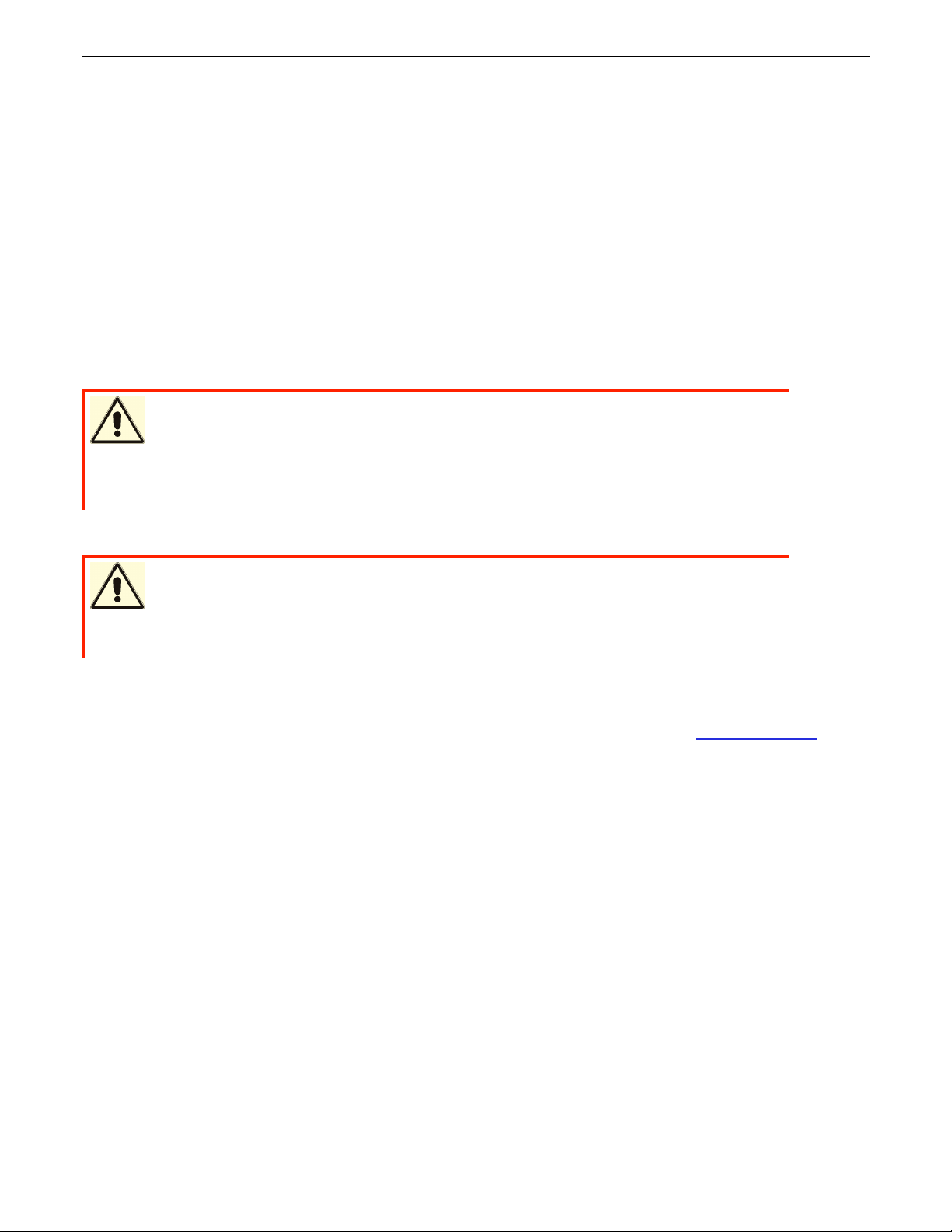
2. Install the REV System Software from the included CD.
3. Power off your computer.
Iomega® REV™ Autoloader 1000—User’s Manual
Copyright © 2004. Iomega Corporation. All rights reserved. Page 8 of 82
Page 9
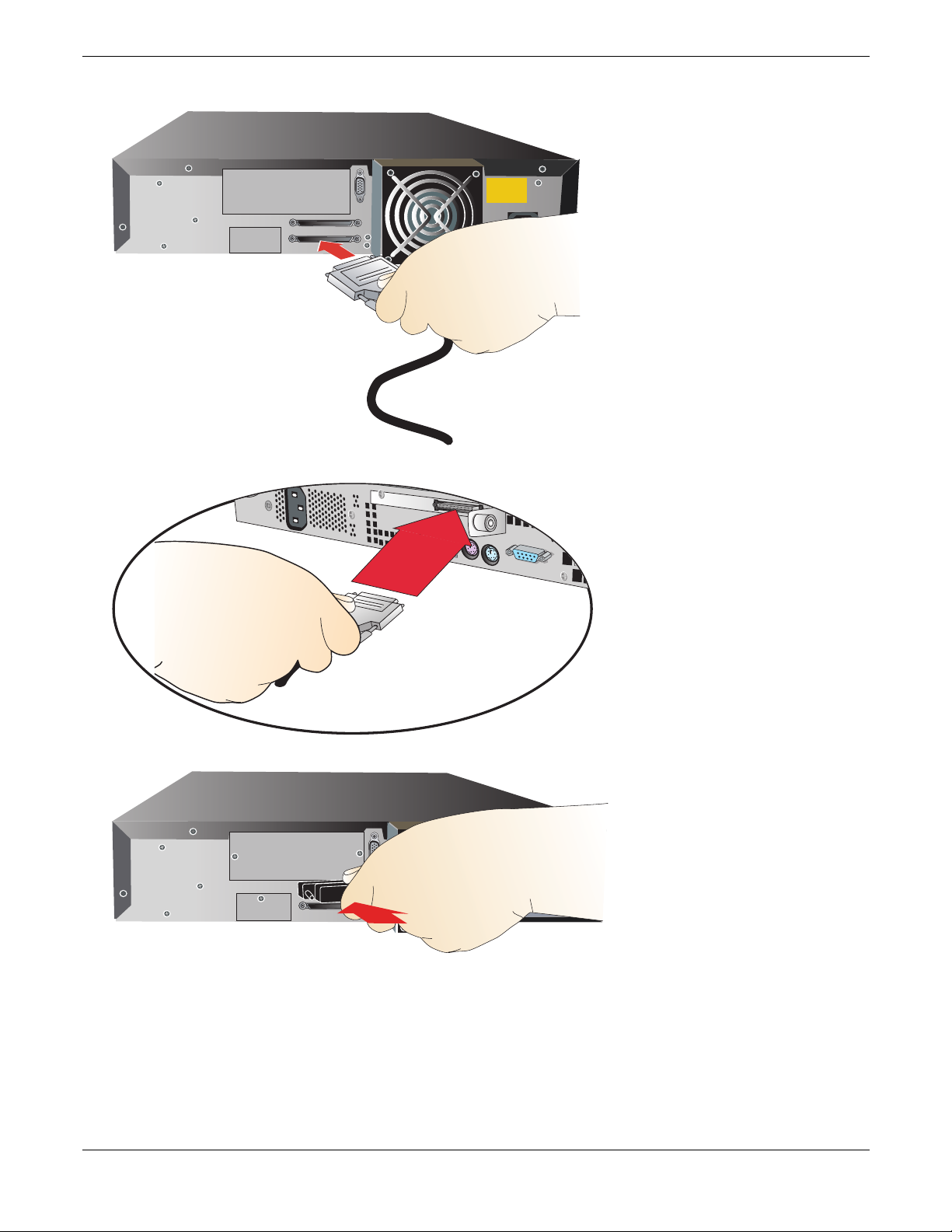
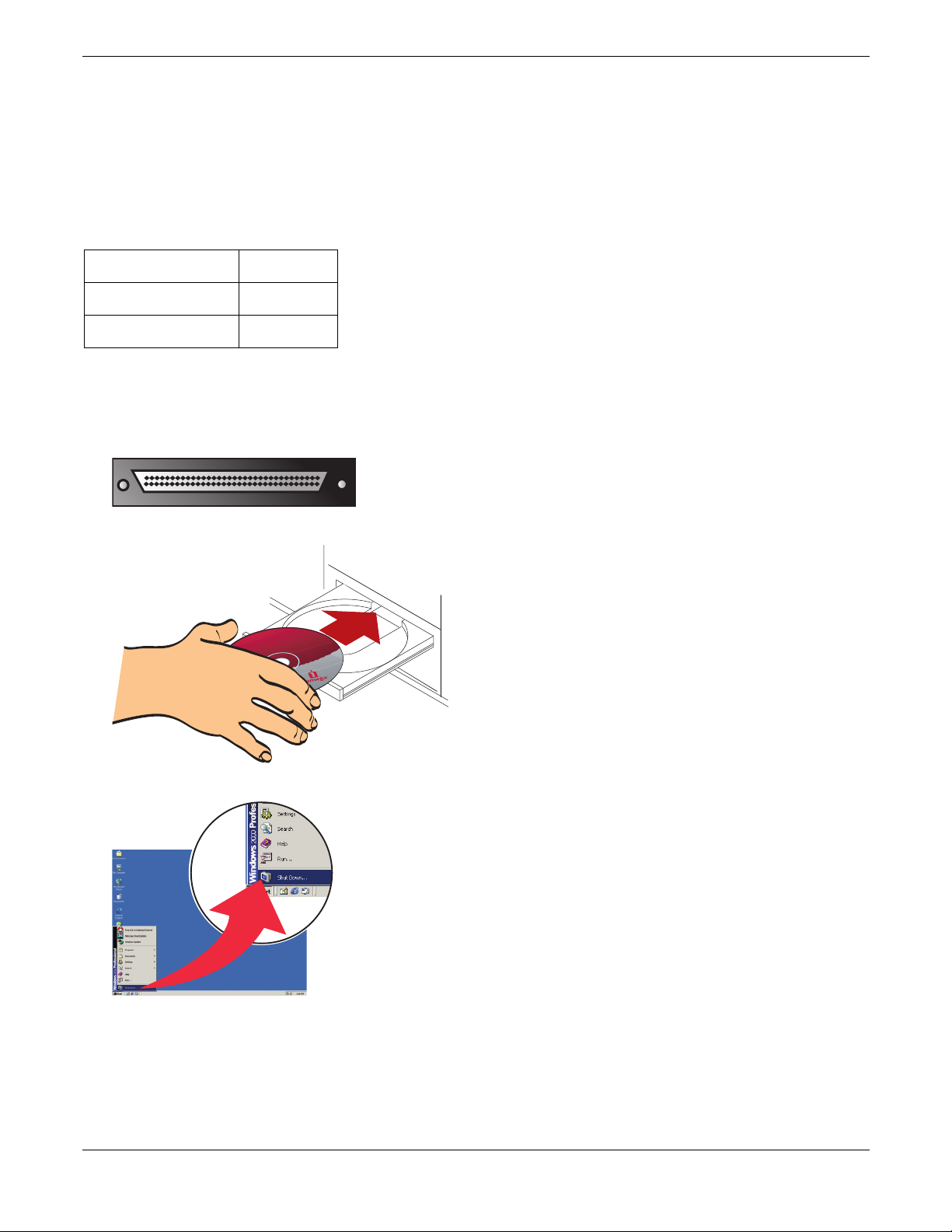
4. Connect the 68-pin wide connector on the SCSI cable to the autoloader.
5. Connect the other end of the cable to the SCSI port on your computer.
6. Connect the included SCSI terminator or another SCSI device to the autoloader’s other SCSI connector.
Iomega® REV™ Autoloader 1000—User’s Manual
Copyright © 2004. Iomega Corporation. All rights reserved. Page 9 of 82
Page 10
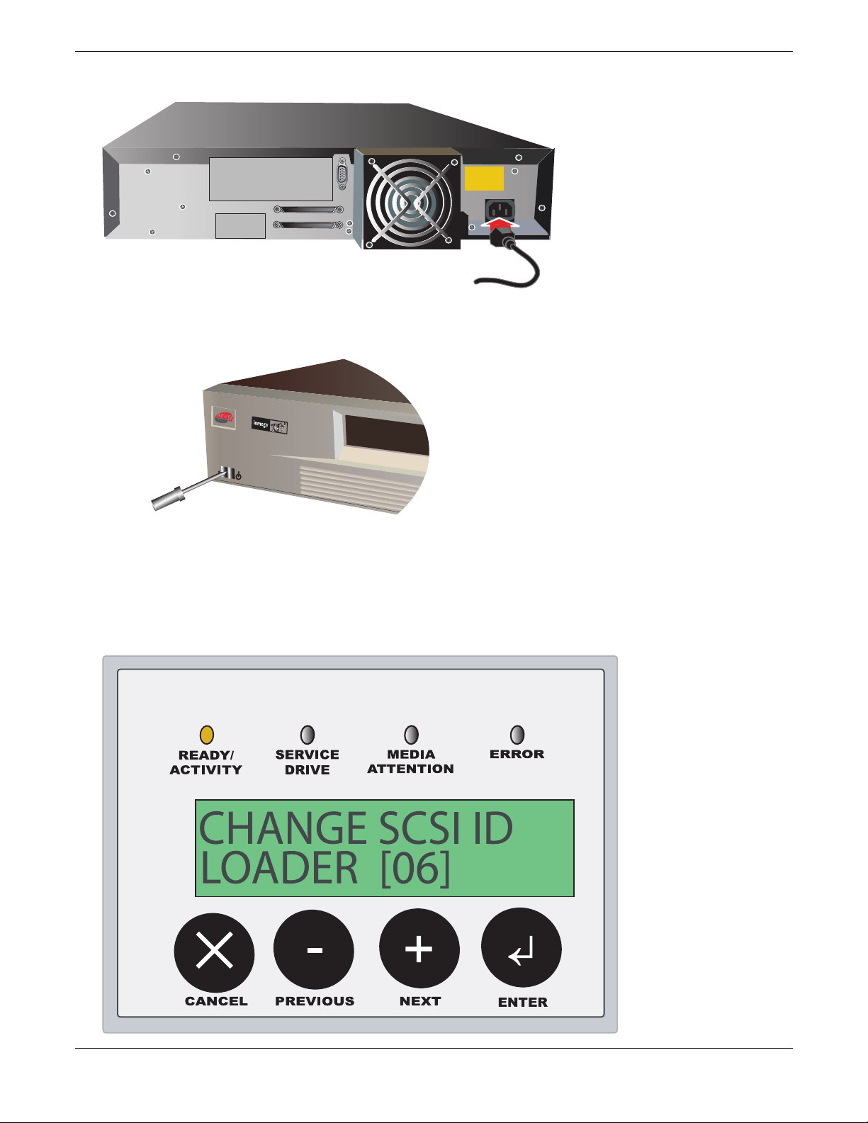
7. Connect the power supply to the autoloader, and then plug the power supply into an electrical outlet.
Autoloader
1000
8. Power up the autoloader. Use a long, narrow device, such as a pencil, to press the left side of the power
switch.
9. Using the Operator Control Panel (OCP), set the autoloader to an appropriate SCSI ID.
You can use any SCSI ID that is not already in use by your computer or another device. The REV autoloader
requires 2 SCSI IDs. By default the autoloader uses IDs 4 and 6. See your SCSI card’s utility or drive
properties for information on the IDs of connected devices. ID 7 is generally reserved for the SCSI adapter
card. See section 6 for more information on using the OCP.
Iomega® REV™ Autoloader 1000—User’s Manual
Copyright © 2004. Iomega Corporation. All rights reserved. Page 10 of 82
Page 11
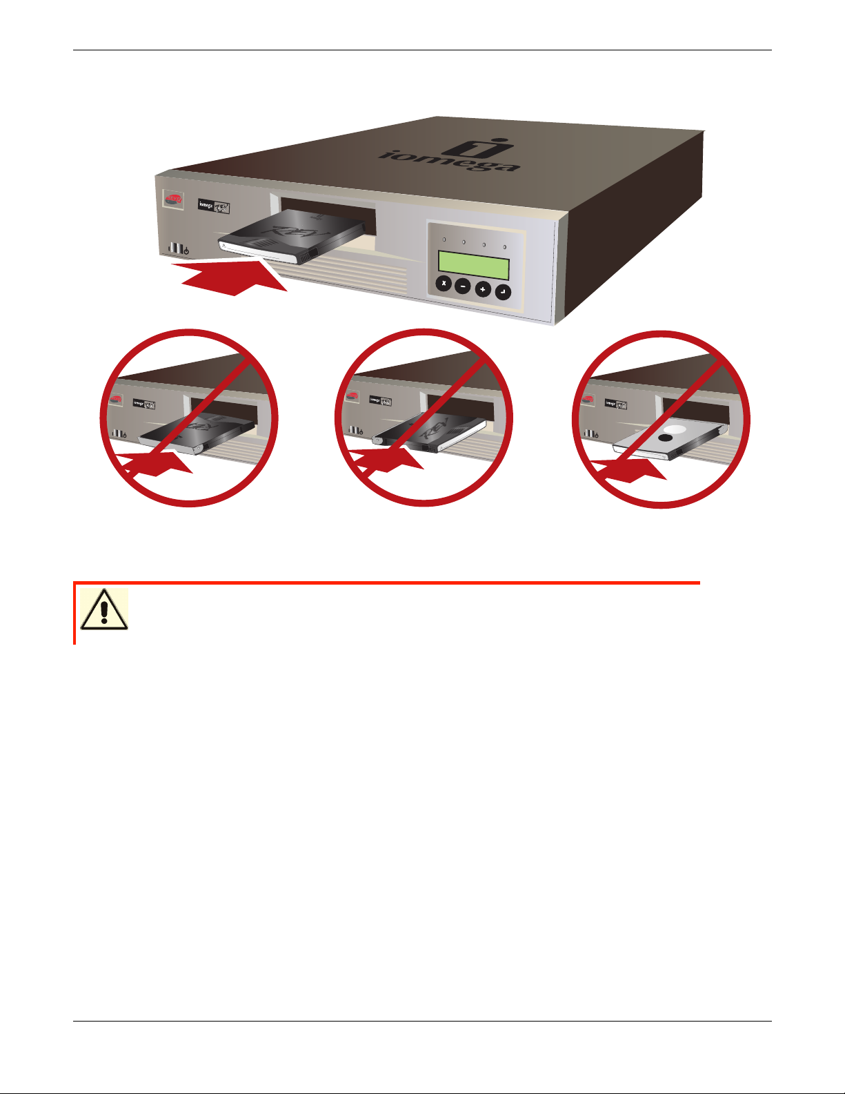
10. Power up your computer. Insert up to 10 REV cartridges into the device to begin using your autoloader. See
3
5
G
B
/
9
0
Native/Co
mpres
sed
G
B
A
u
toloa
d
e
r
100
0
Aut
o
l
oa
d
e
r
1000
35
G
B
/
90
N
a
t
i
v
e
/
C
o
m
p
r
e
s
s
e
d
G
B
Autol
oad
e
r
1000
35
G
B
/
90
N
a
t
i
v
e
/
C
o
m
p
r
e
s
s
e
d
G
B
section 6 for more information.
A
u
toloader
1
000
R
E
ADY
/
S
E
R
VI
A
C
CT
E
I
VI
T
Y
M
E
D
DRI
I
A
VE
E
RRO
A
T
T
R
EN
T
I
O
N
CA
NC
E
L
PRE
V
I
OUS
N
EXT
ENT
E
N
E
R
TE
R
CAUTION Insert the REV cartridge as shown above. Improper insertion may
damage the cartridge, autoloader, or drive.
Iomega® REV™ Autoloader 1000—User’s Manual
Copyright © 2004. Iomega Corporation. All rights reserved. Page 11 of 82
Page 12

4 Features and Physical Description
4.1 Equipment Description
The Iomega® REV™ Autoloader 1000 provides a simple way to backup, archive, and restore your valuable data.
This chapter describes the autoloader and includes the following topics:
Autoloader features
Component descriptions
Autoloader accessories
Related products
4.2 Features
The autoloader includes the following features:
A carousel encircles the REV drive and positions the specified cartridge slot in front of the REV drive. A
robotic cartridge loader moves the cartridges between the cartridge slots and the REV drive.
Storage for up to 10 REV disks. Cartridges are stored in cartridge slots mounted on the carousel.
A cartridge access port for importing or exporting a single cartridge from the autoloader.
An LCD allows you to monitor autoloader operations, select configuration options, and control the cartridge
loader and carousel from the front panel.
The autoloader and the REV drive each include independent Small Computer System Interface (SCSI)
controllers. Each supports independent sets of SCSI messages and commands. The autoloader and the
enclosed REV drive use a wide, low-voltage differential (LVD) SCSI interface.
NOTE: The LVD SCSI interface is also compatible with single-ended (SE) SCSI.
Iomega® REV™ Autoloader 1000—User’s Manual
Copyright © 2004. Iomega Corporation. All rights reserved. Page 12 of 82
Page 13
The autoloader is designed as a standalone unit, but can be mounted in a standard 19-inch rack if desired. Rack
mount kits are available from Iomega.
4.3 Component Descriptions
The following sections describe the major components of the autoloader.
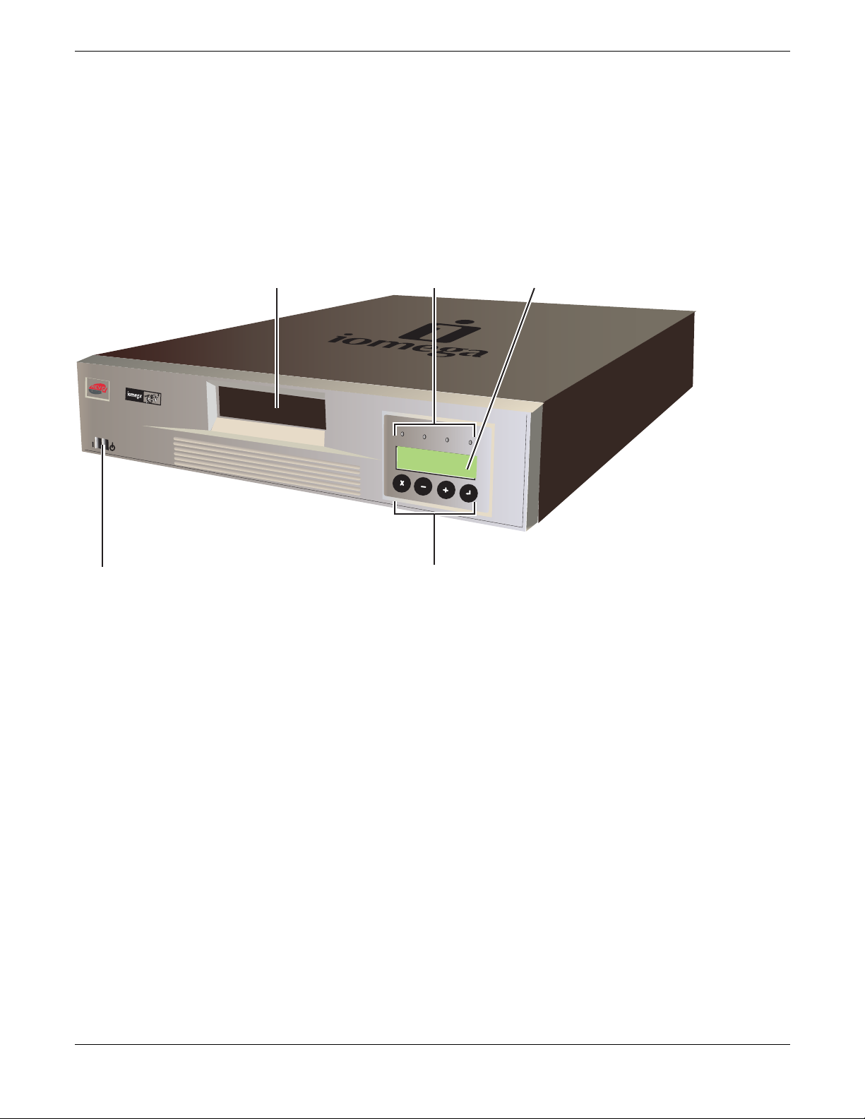
Front Panel Components
Autoloader
1000
READY
S
E
R
V
A
I
C
C
T
E
IV
I
TY
M
E
DI
D
RIV
A
E
ERR
A
T
T
O
R
E
N
T
I
ON
C
A
NC
E
L
PR
EV
I
OU
S
N
EX
T
E
N
T
E
R
( 1 ) Cartridge access port
The cartridge access port allows you to insert or remove cartridges from the autoloader.
Operator Panel
( 2 ) 4 Status LEDs
( 3 ) Liquid crystal display (LCD), 16 characters per line, two lines
( 4 ) Four button keypad
For more information about the operator panel and menu operations, see page 24.
( 5 ) Power switch
The power switch allows you to turn power on and off for the autoloader and the enclosed REV drive. The
switch is recessed into the front panel to prevent the autoloader from being accidently turned off during
operation.
Iomega® REV™ Autoloader 1000—User’s Manual
Copyright © 2004. Iomega Corporation. All rights reserved. Page 13 of 82
Page 14
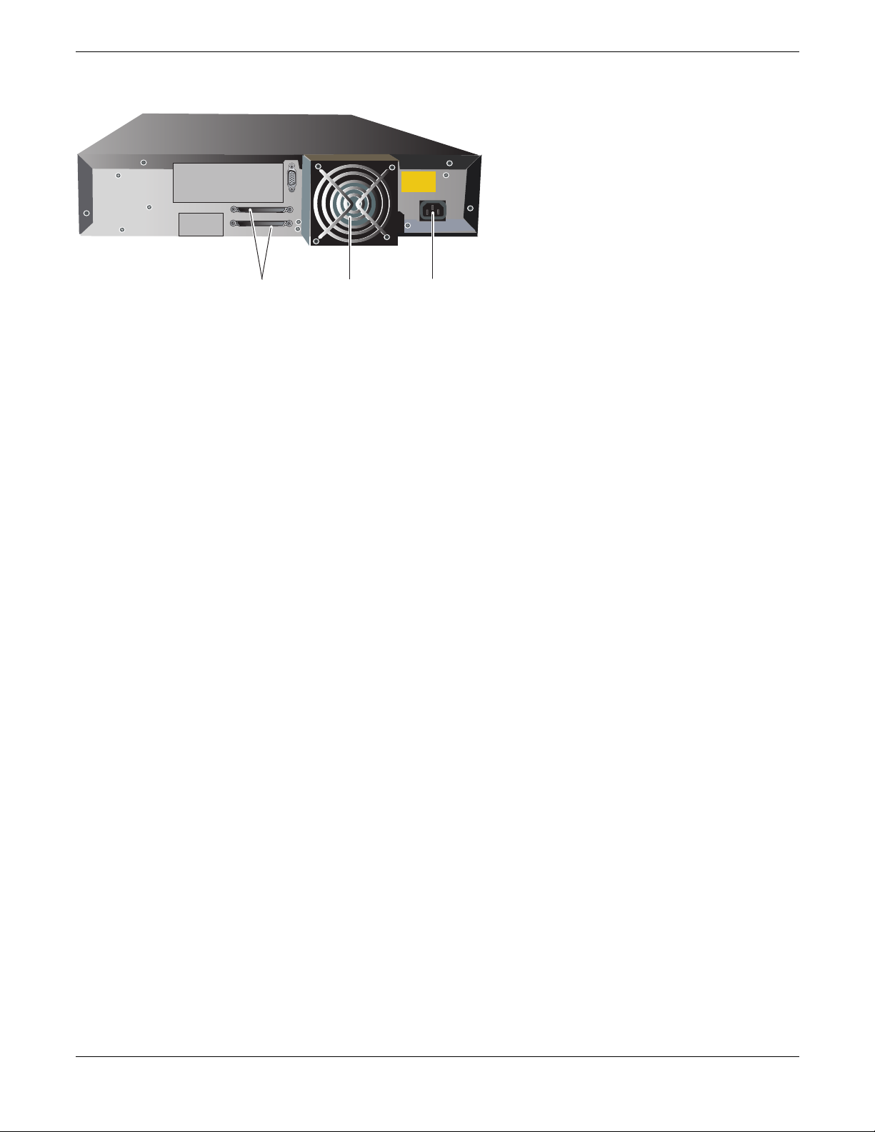
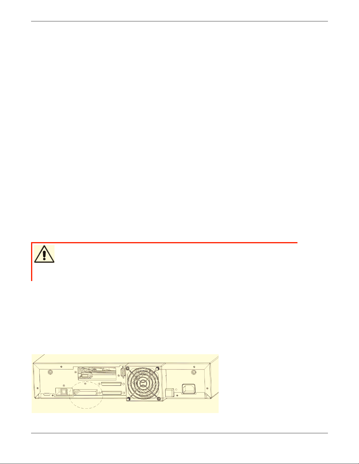
Back Panel Components
( 1 ) SCSI Connectors
The autoloader has two wide SCSI connectors for connecting the autoloader and REV drive to a single
SCSI bus. The connectors can accommodate either of the following:
– A shielded male, high-density wide (68-pin) SCSI cable
– A wide external terminator
The wide SCSI configuration allows up to 16 devices (including one or more initiators) to be attached to a
single SCSI bus. See SCSI Interface Specification on page 76 for more information about the SCSI
interface.
( 2 ) Fan
The system fan provides cooling for the autoloader and the REV drive.
( 3 ) Power cord connection
The power cord connection provides AC power and chassis grounding to the autoloader and the REV drive.
REV drive
The autoloader contains one REV drive. The REV drive can store up to 70 GB of compressed information on a
single data cartridge (assuming an average compression ratio of 2:1).
Cartridge Slots and Carousel
The carousel stores up to ten REV disks. The carousel consists of a drive belt, guides, and gears that move the
cartridges into position in front of the REV drive. Each cartridge is installed in a cartridge slot that ensures that the
cartridge is properly aligned to be inserted into the REV drive.
Cartridge Loader
The cartridge loader moves cartridges between the cartridge slots and the REV drive. When a cartridge slot is
positioned in front of the REV drive, the loader grips the sides of the cartridge and slides it forward or backward
between the slot and REV drive. The loader then releases the cartridge and pushes it firmly into the drive or slot.
Enclosure
The autoloader is housed in a 2 EIA units (2u) high desktop enclosure with a black, textured finish.
Autoloader Accessories and Related Products
The following accessories and products, available from Iomega, are intended for use with the autoloader:
REV disks (available in single and multi-packs)
Rack mount kit
Remote Management Unit (RMU)
Iomega® REV™ Autoloader 1000—User’s Manual
Copyright © 2004. Iomega Corporation. All rights reserved. Page 14 of 82
Barcode Reader (BCR)
Barcode labels
Page 15
5 Installation and Setup
This chapter describes:
Installing the Optional Remote Management Unit (RMU)
Installing the Optional Bar Code Reader (BCR)
Installing the Autoloader as a Desktop Unit
Installing the Autoloader in a Rack
5.1 Installing the Optional Remote Management Unit (RMU)
5.1.1 Contents of the Kit:
RMU with built-in 10/100 Ethernet LAN Card.
5.1.2 Required Tools:
T10 Torx wrench or small flat-blade screwdriver
5.1.3 Mounting Instructions:
CAUTION Electrostatic discharge!
To avoid destruction of the ESD sensitive components, please touch unit
cover or rear panel before installing the RMU.
The RMU is to be mounted on the rear of the device.
1. Power off the autoloader.
2. Remove the power cord.
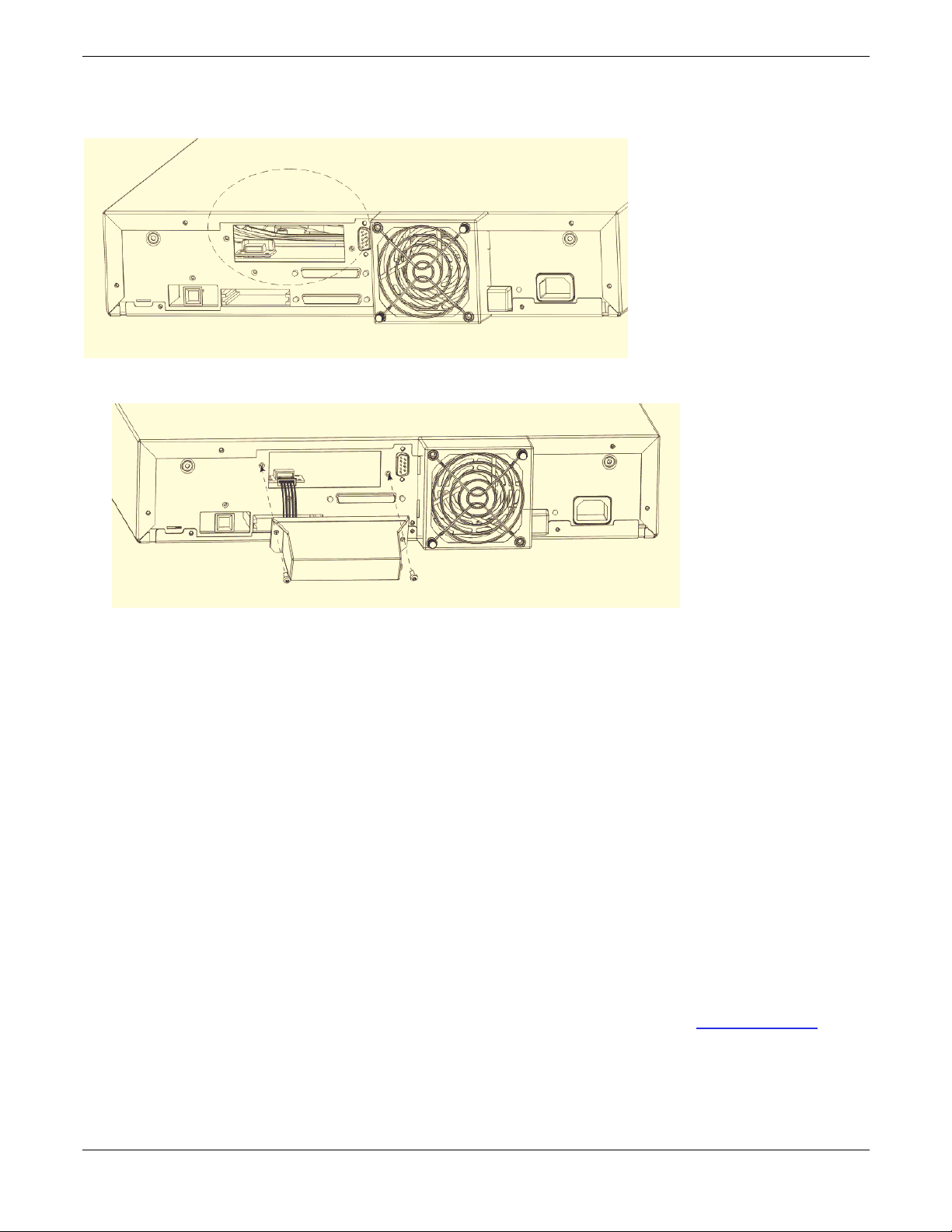
3. Remove the protective covering (located on the autoloader’s rear panel). Save the screw. Save and
store the cover plate; you may use this plate later after removing the RMU.
4. Align the LAN card in the rails and insert into the unit.
Iomega® REV™ Autoloader 1000—User’s Manual
Copyright © 2004. Iomega Corporation. All rights reserved. Page 15 of 82
Page 16
5. Attach the unit with the previously removed screw.
6. Attach an Ethernet cable to the RMU.
7. Connect the other end of the Ethernet cable to a router, switch, hub, or other computer. You may need a
crossover cable to connect the RMU directly to another computer.
8. Power ON the autoloader and wait for initialization to complete.
9. Configure the RMU via OCP, see section 6 of this manual.
You will need to set either a static IP address or enable DHCP before using the RMU.
5.2 Installing the Optional Bar Code Reader (BCR)
5.2.1 Contents of the Kit:
Barcode reader.
Barcode labels (20)
5.2.2 Required Tools:
T10 Torx wrench or small flat-blade screwdriver.
5.2.3 Mounting Instructions:
CAUTION Electrostatic discharge!
To avoid destruction of the ESD sensitive components, please touch unit
cover or rear panel before installing the BCR.
The barcode reader is to be mounted on the rear of the autoloader.
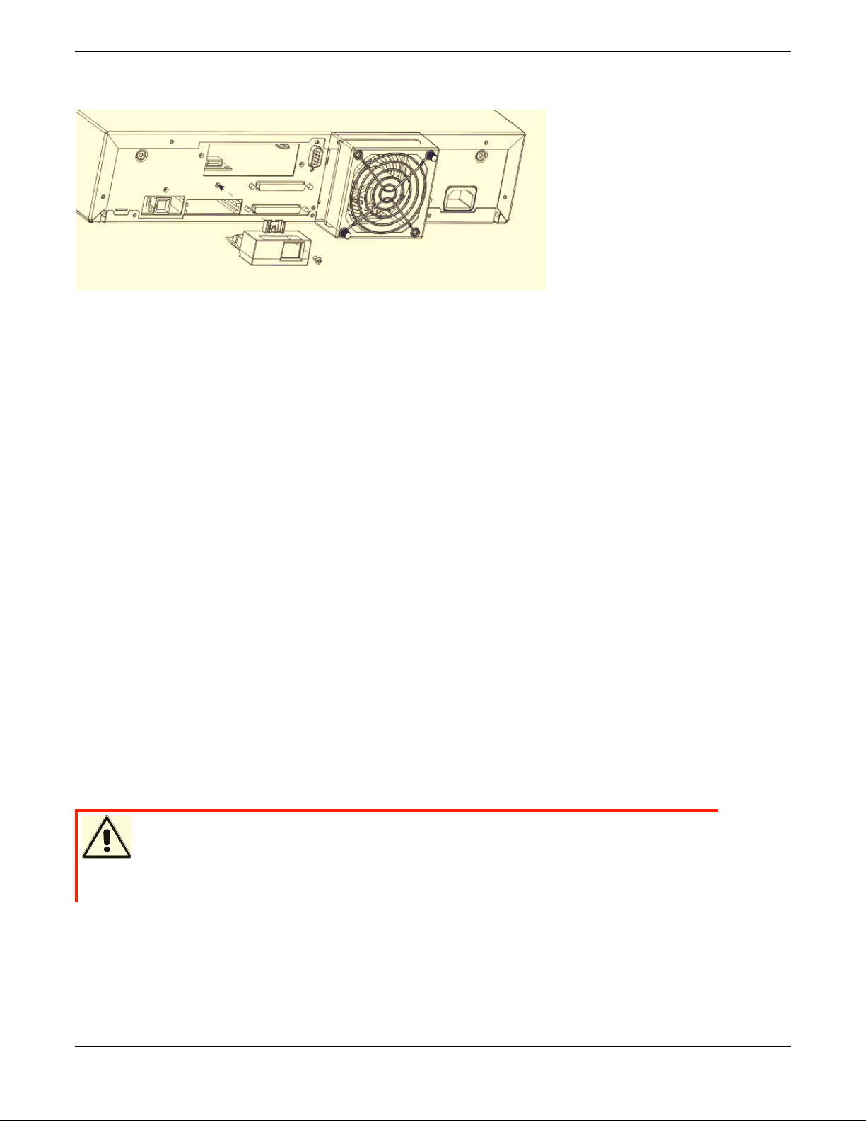
1. Power OFF the autoloader.
2. Disconnect the power cord from the outlet. Remove the SCSI cable(s) and power cord from the rear
panel of the autoloader.
Iomega® REV™ Autoloader 1000—User’s Manual
Copyright © 2004. Iomega Corporation. All rights reserved. Page 16 of 82
Page 17
3. Remove the cover plate from the rear panel. Save the screws! Save and store the cover plate; you may
use this plate later after removing the barcode reader.
4. Align the barcode reader with the slot. See the illustration for correct orientation
5. Connect the cable to the barcode controller outlet.
6. Attach the barcode reader with the previously removed screws.
7. Reconnect the SCSI cables and power cord to the autoloader.
8. Power ON the autoloader.
5.2.4 Configuration of the Barcode Reader
1. Enable Barcode Reader through the Operator Control Panel (OCP). Select menu item
CONFIGURATION/BARCODE READER and set BCR CHANGE TO “ON”.
2. The barcode reader is controlled through the host software.
3. The autoloader and host system will sense the presence of the barcode reader.
5.2.5 Barcode Labels
The barcode reader can only operate if barcode labels are present on the REV disks. Visit www.iomega.com to
order the appropriate barcode labels.
Iomega® REV™ Autoloader 1000—User’s Manual
Copyright © 2004. Iomega Corporation. All rights reserved. Page 17 of 82
Page 18
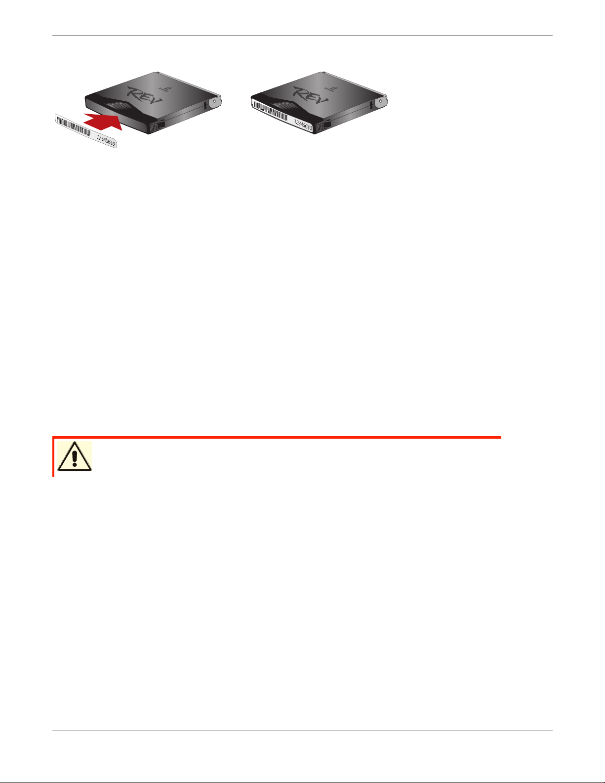
Barcode label placement:
NOTE: Replace the existing REV cartridge label only! Never place the barcode label on top of the REV
cartridge.
5.2.6 Removing the Barcode Reader
1. Disable Barcode Reader through the Operator Panel. Select menu item CONFIGURATION/BARCODE
READER and set BCR CHANGE TO “OFF”
2. Power down the autoloader.
3. Disconnect the power cable from the outlet. Remove the SCSI cable(s) and power cable from the rear
panel.
4. Remove the screws that attach the barcode reader to the rear panel.
5. Unplug the barcode reader connector from the controller outlet.
6. Replace the cover panel on the rear panel.
5.3 Installing the Autoloader as a Desktop Unit
WARNING Do not place anything on top of the autoloader!
5.3.1 Checks Before Installation:
If you install the autoloader as a desktop unit, position the autoloader in a location that is away from dust, dirt, and
debris, and is convenient to the server (host) to which it will be attached. The only restrictions are the length of the
power cord and the length of the SCSI cable.
For a desktop installation, position the autoloader in the following recommended locations:
Away from high-traffic areas, especially if the floor is carpeted.
Out of copy rooms to avoid toner and paper dust. Do not store paper supplies near any unit.
Away from moving air, such as doorways, open windows, fans, and air conditioners.
Off the floor.
In a horizontal position on a flat surface.
Where a REV disk can be easily inserted into the Cartridge Access Port.
Iomega® REV™ Autoloader 1000—User’s Manual
Copyright © 2004. Iomega Corporation. All rights reserved. Page 18 of 82
Page 19

5.3.2 Connecting Power
1. Plug the power cord into the receptacle at the rear of the autoloader
2. Plug the other end of the power cord into a grounded electrical outlet.
3. Power on the autoloader.
The autoloader will verify the drive configuration and status, build a valid cartridge inventory log, and calibrate the
robotic cartridge loader.
The OCP’s green READY/ACTIVITY LED (light-emitting diode) will blink during this initialization process.
When the autoloader completes the Power-On Self Test (POST) for the drive and the library, the green
READY/ACTIVITY LED will stop blinking.
The autoloader will be in automatic mode (the default mode) and SQ will appear in the lower right corner of the
OCP display.
For information about the autoloader’s modes of operation, see section 6.3. If a failure occurred, the red ERROR
LED will light up and an error message will be displayed on the OCP. See Troubleshooting and Diagnostics
(section 7).
5.4 Installing the Autoloader in a Rack
You can install the autoloader into a standard 19-inch rack.
Required Tools:
Phillips screwdriver, #2
Torx wrench, T10
5.4.1 Prepare the Autoloader for Installation
CAUTION Make sure there is no SCSI activity on the bus before you power OFF the
autoloader.
If the autoloader is already in operation as a standalone unit, prepare it for installation in the rack as follows:
1. Power off the autoloader using the POWER button on the front panel.
2. Remove the power cord and any cables or terminator attached to the autoloader. Note the configuration
of the cables and terminator for reconnecting them after installing the autoloader in the rack.
5.4.2 Install the Support Rails in the Rack
1. Remove the two support rails from the kit and note how they will be positioned in the rack. When the rails
are properly installed, the shelf flanges will face inward to support the autoloader.
NOTE: The autoloader requires 2 EIA units of rack space for installation.
2. Identify the 2 EIA units required by the autoloader for rail placement.
Iomega® REV™ Autoloader 1000—User’s Manual
Copyright © 2004. Iomega Corporation. All rights reserved. Page 19 of 82
Page 20
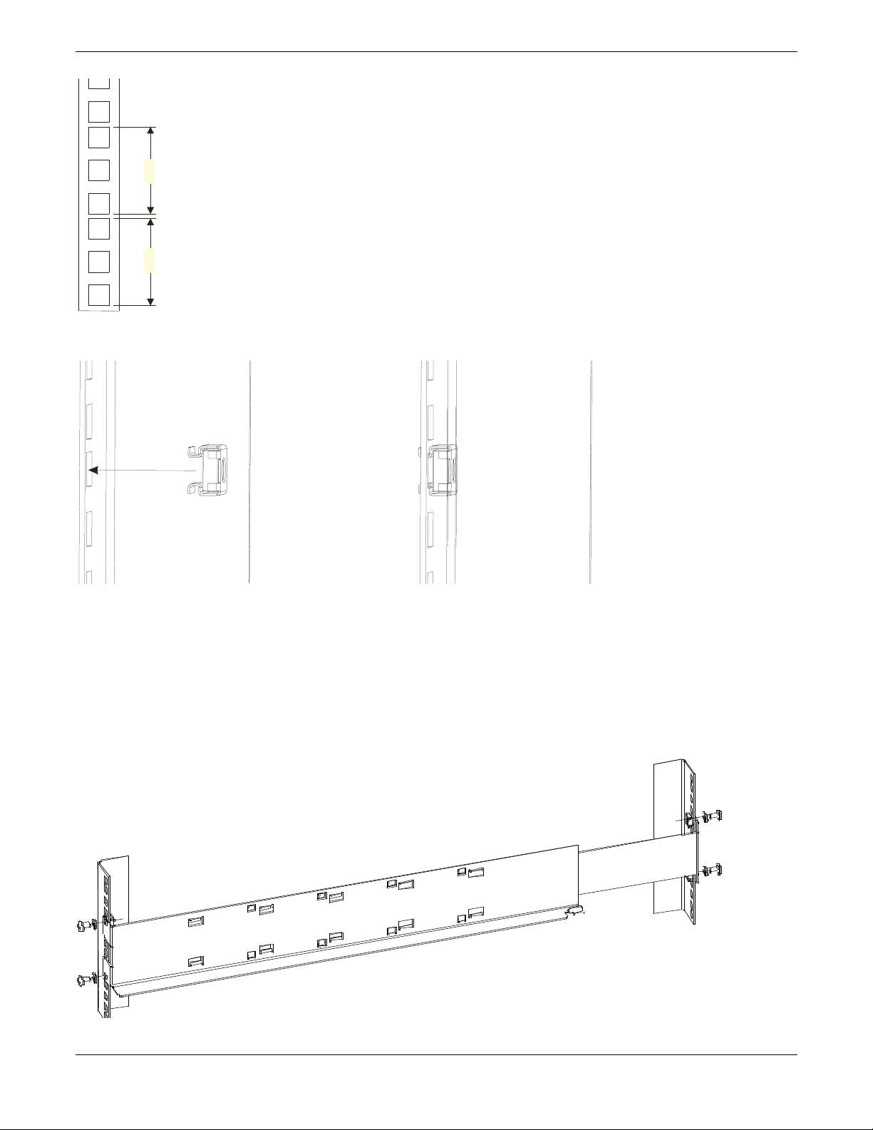
4.45cm
(1.75in.)
4.45cm
(1.75in.)
3. Install the cage clip-nuts (for racks with square mounting holes) from the back side of each rail.
NOTE: To ensure proper installation of the Autoloader in your rack, it is very important to install the clip-nuts in
the correct positions on each rail.
4. Count the holes on the other three rack rails, up or down, to determine the position of the top or bottom
clip-nut.
5. From the front of the rack, position one of the rails on the appropriate side.
6. Position the front flange so that it is on the outside of the strip of mounting holes in the rack.
7. Using a #2 Phillips screwdriver, attach the rail to the rack with screws and washers from the kit.
Iomega® REV™ Autoloader 1000—User’s Manual
Copyright © 2004. Iomega Corporation. All rights reserved. Page 20 of 82
Page 21
8. Slide the rail pieces apart to match the depth of your rack.
9. Using a #2 Phillips screwdriver, attach the rail to the outside of the rack with screws and washers
supplied with the rack mount kit.
10. Repeat steps 5 through 9 to install the second rail.
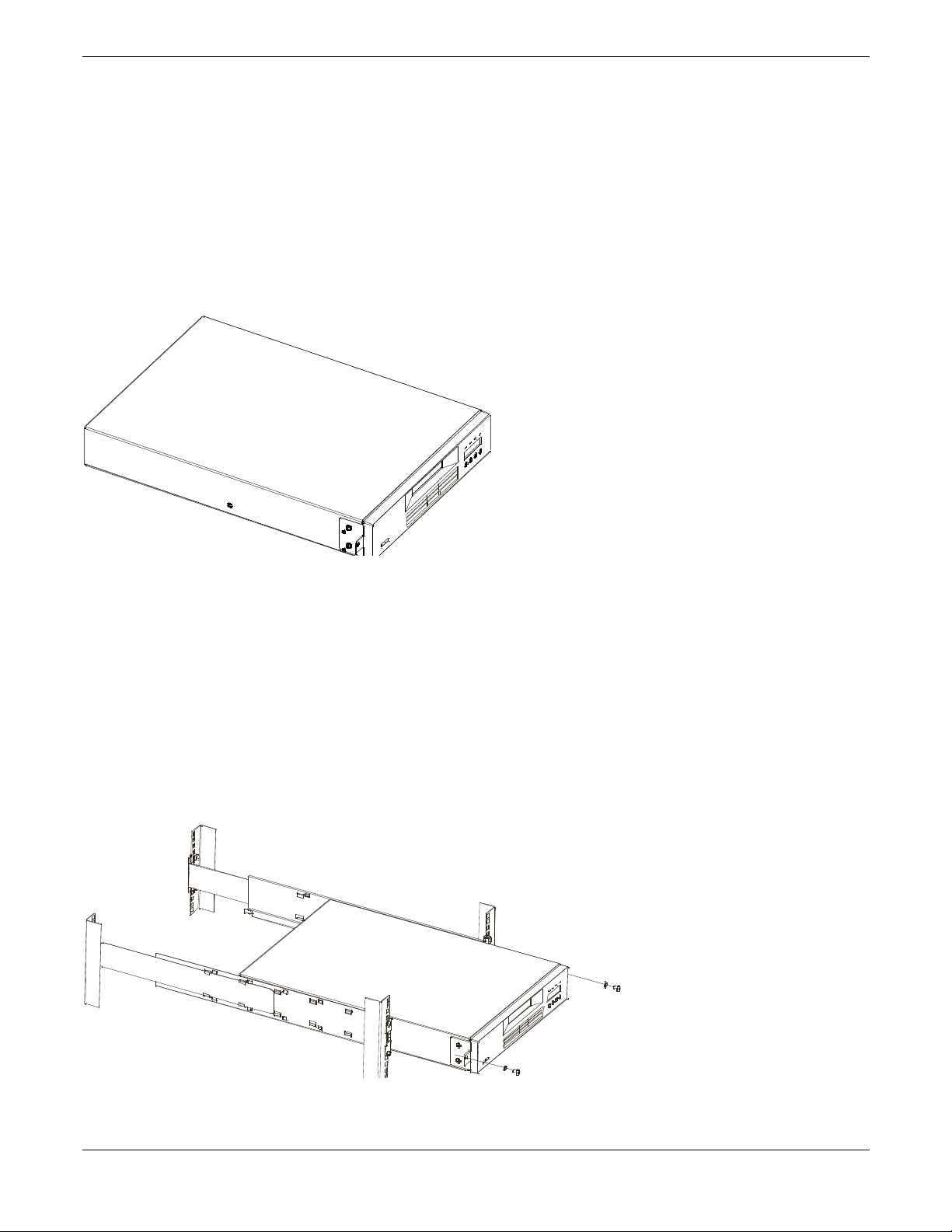
5.4.3 Install the Rack Front Mount Brackets on the Autoloader
1. Determine on which side of the autoloader the rack mount brackets will be attached. The oval hole for
attaching the bracket to the rack will be on the bottom of the arm of the bracket.
2. Using the Torx wrench, remove the two screws on each side of the autoloader cover.
3. Position the correct bracket, as determined in Step 1, on each side of the autoloader and secure by
reusing the original screws.
5.4.4 Secure the Autoloader to the Rack
1. From the front of the rack, position the autoloader on the shelf flanges between the support rails. Slide it
toward the rear of the rack until the brackets contact the rack’s mounting holes.
NOTE: Make sure that the tabs on the back of each shelf flange are fully engaged in the slots at the rear of the
autoloader.
2. Place one screw and washer from the rack mount kit into the hole in the front of each bracket. Take care
that the screws line up with the holes containing the remaining installed clip-nuts. Use a #2 Phillips
screwdriver to tighten the screws.
Iomega® REV™ Autoloader 1000—User’s Manual
Copyright © 2004. Iomega Corporation. All rights reserved. Page 21 of 82
Page 22
6 Operation and Maintenance
Autoloader
1000
This chapter describes the requirements for using the autoloader, including information about:
Powering on the System
Using the Operator Control Panel and Menu Options
Operational Modes
Configuration
Operation
Loading and Unloading REV Disks
Shipping
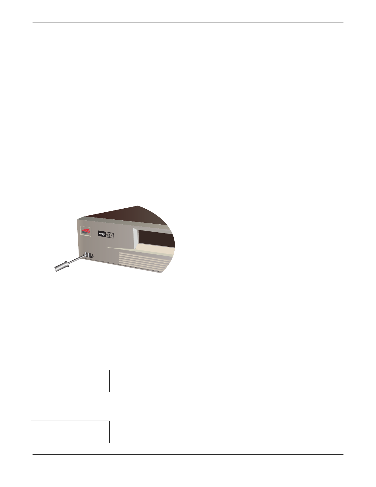
6.1 Powering on the System
Switch on power using the POWER button located on the front panel, after the power cord and the SCSI cable
are connected. The autoloader will power up.
If an RMU is installed, look on the rear panel of the autoloader and verify that the RMU’s green LED is on. If the
green LED is not on, check the connection to the RMU, see Installing the Optional Remote Management Unit
(RMU) in section 5.1. Otherwise call technical support.
When the autoloader powers up, or resets, it goes through several internally controlled processes that allow it to
get initialized and running. While those processes are happening, the operator panel shall have appropriate
information displayed to keep the user informed. When the autoloader finishes powering up, it will display the
Current Drive mount status in the ‘Home Screen’. It also indicates that sequential mode is ON by posting the SQ
string.
If the drive is empty, the following status will be displayed:
Drive empty
12345-7890 SQ
If the autoloader detects that a cartridge is loaded when it first powers on, the following status will be displayed on
the operator panel:
Drive loaded
12345-7890 SQ
Iomega® REV™ Autoloader 1000—User’s Manual
Copyright © 2004. Iomega Corporation. All rights reserved. Page 22 of 82
Page 23
In this example, there is no cartridge in slot 6. Inventory status will be displayed as an 10-character string.
Inventory status characters
Current Drive Status/Activity
Inventory Status
The inventory status characters will be represented as follows:
Character Meaning
1 … 9, 0 Slot Full—uses the slot numbers 1 to 10 (0 represents 10).
– Slot Empty—a dash is displayed as a place holder
n /
(where n represents
the slot number)
? The cartridge is nearing the end of its life
A cartridge that is being loaded, unloaded, imported, exported, or is loaded in the
drive, will be represented by the slot number alternating with the block
invalid format, or has reached the end of its life. An invalid cartridge will be identified
the same way.
Drive loaded
12!45-7890 SQ
LEDs
character
The 4 LEDs (1-4) are updated during power up and reset sequences. Upon power up or software reset, the
autoloader will illuminate all LEDs as soon as power on self-test (POST) allows. This will help the user to verify if
all LEDs are functional.
When mechanical initialization starts, the READY/ACTIVITY LED (1) will flash at a rate of approximately 1-second
per cycle, 50% duty cycle.
When the mechanical initialization is complete, the READY/ACTIVITY LED (1) will stop flashing and be constantly
illuminated.
If an autoloader failure occurs, the READY/ACTIVITY LED (1) will be turned off and the error LED (4) will be
illuminated. The operation panel will also display an appropriate error code to help identify the failure.
Iomega® REV™ Autoloader 1000—User’s Manual
Copyright © 2004. Iomega Corporation. All rights reserved. Page 23 of 82
Page 24
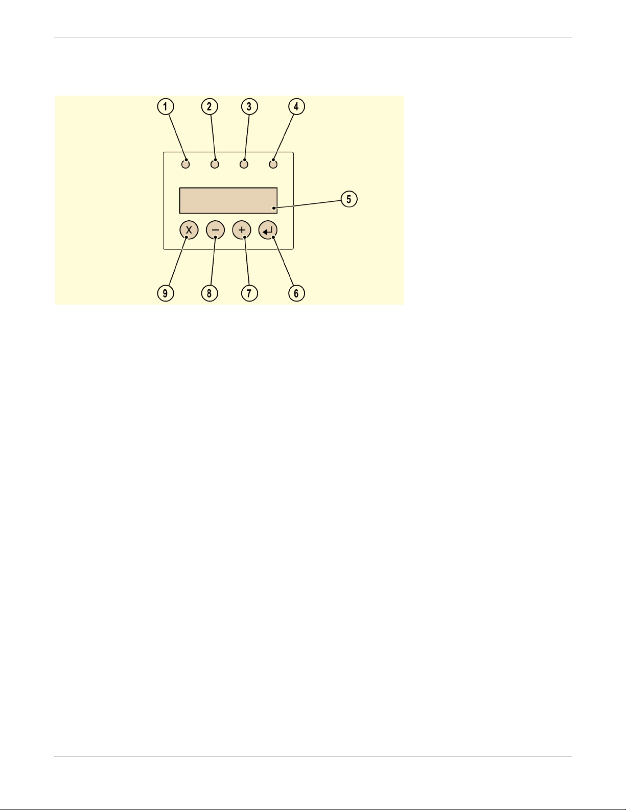
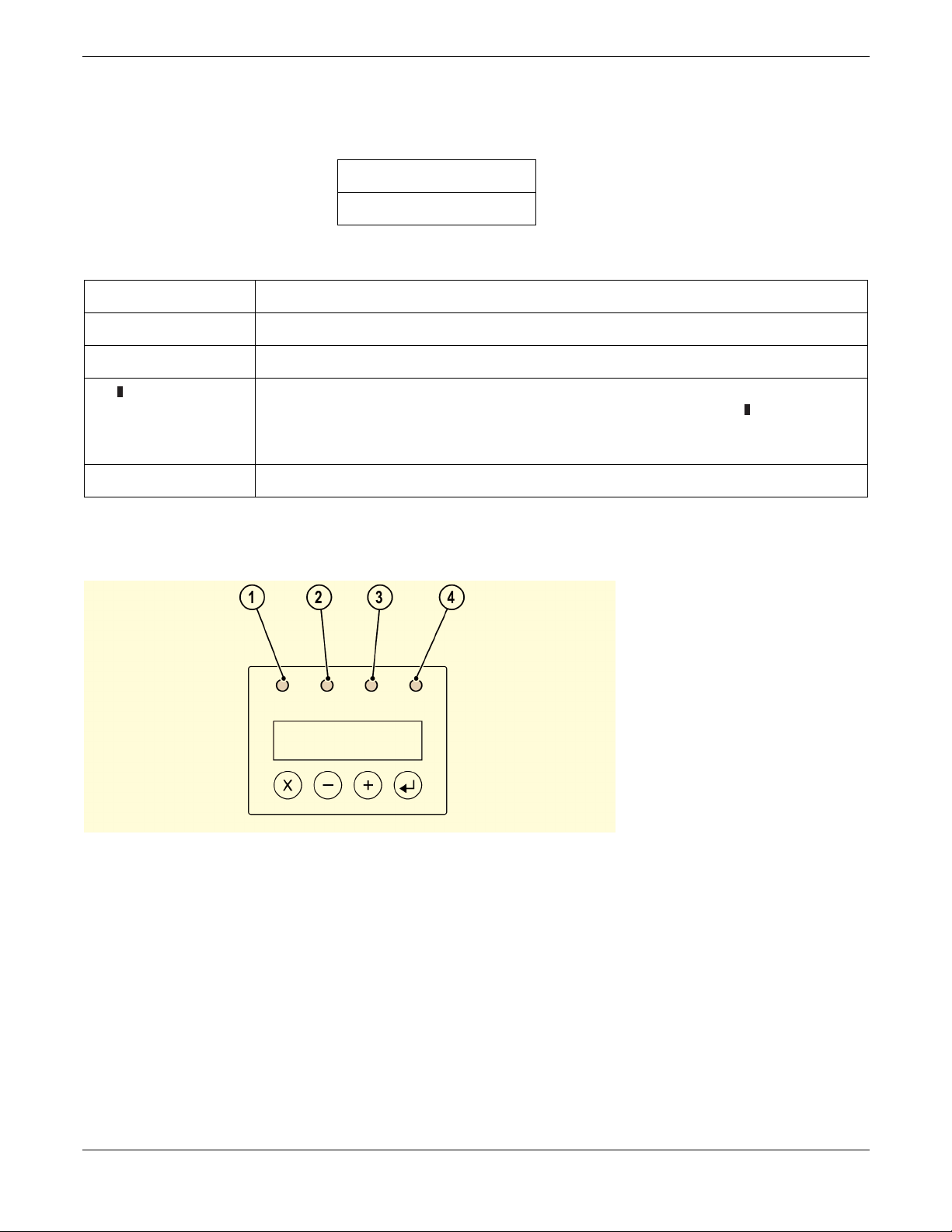
6.2 Using the Operator Control Panel and Menu Options
( 1 ) READY/ACTIVITY, Green LED
It is lit any time the unit is powered on and able to function. It should blink whenever there is autoloader or
drive activity.
( 2 ) SERVICE DRIVE, Amber LED
The drive needs to be serviced. The LED will be turned off after the drive is serviced successfully.
( 3 ) MEDIA ATTENTION, Amber LED
Indicates that a REV cartridge is bad, marginal or invalid. It will be cleared when all invalid cartridges have
been exported from the autoloader.
( 4 ) ERROR, Red LED
Unrecoverable autoloader or drive failure. A message is displayed at the same time on the screen. It will be
cleared when the error state is resolved.
( 5 ) LCD display, consisting of two lines with 16 characters per line
The screen displays actions and status information, menu items or error messages equivalent to the
operation mode.
( 6 ) ENTER, button [↵]
It is used in interaction mode. Push the enter button to go to a sub menu or to force a robotic action.
( 7 ) NEXT, button [+]
It is used in interaction mode to navigate through menu items.
( 8 ) PREVIOUS, button [–]
It is used in interaction mode to navigate through menu items.
( 9 ) CANCEL, button [X]
It is used in interaction mode. Push the CANCEL button to cancel a user action and return to the last menu
item.
Iomega® REV™ Autoloader 1000—User’s Manual
Copyright © 2004. Iomega Corporation. All rights reserved. Page 24 of 82
Page 25

6.3 Operational Modes
The operational modes affect how the autoloader loads cartridges into the drive. The different modes can be
selected at the configuration menu in the OCP. They are stored in the NVRAM and are valid also after Power ON.
There are 2 basic modes that the OCP operates in. First is the User Interaction mode. This mode is employed
when a user is pushing buttons on the OCP (Operator Control Panel). The second mode is the System Driven
mode. This is the normal mode of operation. In this mode, the OCP displays status associated with the actions
that were caused from commands issued via the Drive’s serial interface. When an OCP button is pressed and
released, the OCP automatically transitions to User Interaction mode. User Interaction mode will continue until 1.5
minutes after a user stops pushing buttons, or the requested robotic action stops; whichever is longer. At this time
the OCP will return to System Driven mode.
If necessary, the OCP will automatically transition to the System Driven mode. When this occurs, the autoloader
must remember what the User was doing before the display mode changed. Therefore the next button pressed
will only transition the OCP to the User Interaction mode from the System Driven mode.
6.3.1 Automatic Mode
Automatic Mode is the default setting and allows the autoloader to switch between Random and Sequential Mode
depending on the SCSI command received. In this mode Sequential Mode is activated after Power On.
Every MOVE MEDIUM, READ ELEMENT STATUS or INITIALIZE ELEMENT STATUS command disables
Sequential Mode and activates Random Mode. The unit will switch back to Sequential Mode with every OCP
initiated Load Command.
6.3.2 Random Mode
In Random Mode the Media Exchanger SCSI target is visible on the SCSI bus, i.e. the autoloader allows the host
application software to select any cartridge in any order. Cartridges can be moved by MOVE MEDIUM commands
in random order. Unload commands to the drive should not be executed.
6.3.3 Sequential Mode
In Sequential Mode the Media Exchanger is no longer visible on the SCSI bus. Cartridge replacements are
initiated by an ‘Unload’ command sent to the drive.
Sequential Mode presumes that the first cartridge was previously loaded to the drive, i.e. the operator determines
the first cartridge to load by loading the desired cartridge into the drive using the ‘Load Cartridge’ menu item on
the OCP. When the first disk is unloaded with a drive ‘Unload’ command, the autoloader removes the cartridge
from the drive and puts it in its original slot. After that, the next cartridge in order will be moved into the drive. This
queue stops if the last cartridge has been ejected and unloaded from the slot.
In Sequential Mode the display shows the following screen where the string ‘SQ’ indicates that Sequential Mode
is activated:
Drive empty
12345-7890 SQ
To further determine how you want cartridges loaded into the drive while in Sequential Mode, you can set Loop
Mode and Autoload Mode from the OCP.
Iomega® REV™ Autoloader 1000—User’s Manual
Copyright © 2004. Iomega Corporation. All rights reserved. Page 25 of 82
Page 26

6.3.4 Loop Mode
Loop Mode is a special type of Sequential Mode. The cartridge exchange queue will not terminate with the last
cartridge but restart with the first cartridge. This mode allows endless backup operation without user interaction.
6.3.5 Autoload Mode
This is also an option of Sequential Mode and could be combined with Loop Mode. The first cartridge will be
loaded automatically if the unit powers up with an empty drive. In this case user interaction via OCP is not
required.
6.3.6 OCP Philosophy
During the following discussion of the OCP operation, several functional nuances may be clarified by defining
several rules the OCP must abide by. These rules of operation constitute a ‘philosophy’.
Any operational conflict between commands received over serial interface and those entered via the front panel
will be avoided with a reservation mechanism on a ‘first-come, first-served’ basis. Any reservation by OCP is
canceled by an OCP logout or the timeout, which cancels the User Interaction Mode.
Robotic firmware will not allow a user to select an impossible request. Those situations will include, but are not
limited to:
Importing to a full slot
Exporting from an empty slot
Mounting (Loading) from an empty slot
Dismounting (Unloading) an empty drive
Any error detected by the library or drive controller and not recoverable through predetermined software
algorithms, will be considered as fatal. An error code will be displayed on the LCD and the error LED will become
illuminated. The error code will remain on the OCP until a button is pressed, the OCP will return to the Home
Screen.
Numeric error codes are only used for unrecoverable, fatal errors, otherwise text status messages are provided.
Iomega® REV™ Autoloader 1000—User’s Manual
Copyright © 2004. Iomega Corporation. All rights reserved. Page 26 of 82
Page 27

6.4 OCP—Menu Trees
6.4.1 User Go Offline Mode with Protection
6.4.2 User Go Offline Mode without Protection
Iomega® REV™ Autoloader 1000—User’s Manual
Copyright © 2004. Iomega Corporation. All rights reserved. Page 27 of 82
Page 28

6.4.3 OCP User Interaction Mode
Iomega® REV™ Autoloader 1000—User’s Manual
Copyright © 2004. Iomega Corporation. All rights reserved. Page 28 of 82
Page 29

6.4.4 Information
Iomega® REV™ Autoloader 1000—User’s Manual
Copyright © 2004. Iomega Corporation. All rights reserved. Page 29 of 82
Page 30

6.4.5 Commands
Iomega® REV™ Autoloader 1000—User’s Manual
Copyright © 2004. Iomega Corporation. All rights reserved. Page 30 of 82
Page 31

Configuration
Iomega® REV™ Autoloader 1000—User’s Manual
Copyright © 2004. Iomega Corporation. All rights reserved. Page 31 of 82
Page 32

Iomega® REV™ Autoloader 1000—User’s Manual
Copyright © 2004. Iomega Corporation. All rights reserved. Page 32 of 82
Page 33

Iomega® REV™ Autoloader 1000—User’s Manual
Copyright © 2004. Iomega Corporation. All rights reserved. Page 33 of 82
Page 34

6.4.6 Diagnostic
Iomega® REV™ Autoloader 1000—User’s Manual
Copyright © 2004. Iomega Corporation. All rights reserved. Page 34 of 82
Page 35

Iomega® REV™ Autoloader 1000—User’s Manual
Copyright © 2004. Iomega Corporation. All rights reserved. Page 35 of 82
Page 36

Iomega® REV™ Autoloader 1000—User’s Manual
Copyright © 2004. Iomega Corporation. All rights reserved. Page 36 of 82
Page 37

6.5 Operation
After you install and configure the autoloader and install your application software on the host computer, the
autoloader performs most operations automatically. Operator intervention includes the following activities:
Monitoring autoloader operation and status
Performing autoloader and REV drive operations
6.5.1 Monitoring Autoloader Operation and Status
During normal operation, the ‘Status screen’ is displayed on the LCD. You can use this screen to monitor
autoloader activities. By default, the ‘Status’ screen displays the current operating status of the autoloader and
REV drive.
To set the operator panel to user interaction mode, press a key. This mode allows you to use the [Enter] or
[Cancel] and [+] or [–] buttons to display options for issuing commands to the autoloader, viewing information
screens, and configuring the autoloader.
6.6 Loading and Unloading REV disks
The ‘Commands’ screen provides options for importing and exporting cartridges, loading and unloading a
cartridge from the REV drive, and updating the cartridge inventory.
6.6.1 Importing and Exporting Cartridges
The Import command under the Library Commands menu allows you to place a cartridge into a specific cartridge
slot through the cartridge access port.
When you issue an Import command, the cartridge carousel moves the specified cartridge slot into position in
front of the cartridge access port and slides the door open. You can then push the cartridge into the slot through
the door. The cartridge loader then grasps the cartridge, pulls it into the autoloader, and closes the door.
The ‘Export’ command allows you to remove a cartridge from a specific cartridge slot through the cartridge access
port. When you issue an ‘Export’ command, the cartridge carousel moves the specified cartridge slot into position
in front of the cartridge access port and slides the door open. The cartridge loader then pushes the cartridge far
enough out through the door to allow you to remove it.
6.6.2 Bulk Exchange
The menu item Bulk Exchange was designed to make the autoloader more user friendly. This item enables a user
to import or export a specific amount of cartridges e.g. this item makes sense if a user wants to exchange a
complete set of cartridges. Bulk Exchange operation starts with slot 1. If a cartridge is available this cartridge will
be exported. It’s up to the user to import a new cartridge or to move to the next slot 2. The same procedure then
takes place for slot 2 to slot 10.
6.6.3 Load and Unload a Cartridge
The load cartridge command under the ‘Commands’ menu allows you to load the cartridge in the specified slot
into the REV drive. When you issue a ‘Load cartridge’ command, the cartridge carousel moves the specified
cartridge slot into position in front of the REV drive. The cartridge loader then extracts the cartridge from the
cartridge slot and inserts it into the REV drive.
The ‘Unload cartridge’ command causes the REV drive to unload the disk from the disk path and eject the
cartridge. After the cartridge is ejected, the cartridge carousel moves the slot from which the cartridge originated
Iomega® REV™ Autoloader 1000—User’s Manual
Copyright © 2004. Iomega Corporation. All rights reserved. Page 37 of 82
Page 38

into position in front of the REV drive. The cartridge loader then extracts the cartridge from the REV drive and
returns it to the cartridge slot.
6.6.4 Write Protected Media
If the drive detects write-protected media, an internal bit is set and the autoloader posts the “WP” string on the
display indicating write-protected media is loaded in the drive.
The display shows the following status:
Drive loaded
12345-7890 WP
As soon as the write protected media is ejected, the drive resets the internal bit and the “WP” string on the display
is removed. See the REV System Software help for information on write-protecting media.
6.7 Shipping
If you need to ship the autoloader, use the original shipping carton and packing materials to prevent damage. The
shipping carton and packing materials are not intended to be used for shipping items other than or in addition to
the autoloader.
Iomega® REV™ Autoloader 1000—User’s Manual
Copyright © 2004. Iomega Corporation. All rights reserved. Page 38 of 82
Page 39

7 Troubleshooting and Diagnostics
7.1 General Guidelines
The autoloader includes features to support troubleshooting and diagnostic operations.
If the red error LED is on, an error message and error code Will appear on the OCP.
To check if the autoloader is operational the system offers a system test. It is accessible via the item “Diagnostic”
in the system menu. To perform a system test, the REV drive must be empty and at least one slot must contain a
cartridge.
7.2 Error LED/Error Code
1. If the red error LED is on and an error message and error code are displayed on the Status Screen note
the code or information.
2. Press Enter to attempt recovery and initialization. Cycling power may also be necessary.
NOTE: If the Media Attention LED turns red, this is an indication that a drive error occurred pointing to the
media as the possible problem. To determine the drive error code after the cartridge is unloaded and
returned to the I/O Door for removal, perform one of the following procedures to determine the latest
drive error code.
7.2.1 Viewing Error Codes via the OCP
1. Take the autoloader offline.
2. From the OCP, press Enter to access the Information Menu.
3. Press Next to access LOADER INFO.
4. Press Next or Previous until ERROR LOG appears.
5. Press Enter to display the most recent error code.
6. Line one will indicate ERROR CODE 0; line two will show a single hex digit drive error code (see Error!
Reference source not found. in section 7.4).
7. Press Previous to view previous error codes (up to ten error codes are stored).
7.2.2 Viewing Error Codes via the RMU
1. Login as Administrator.
2. Click on Logs and then Drive.
The drive error log table described for serial communication is displayed.
Iomega® REV™ Autoloader 1000—User’s Manual
Copyright © 2004. Iomega Corporation. All rights reserved. Page 39 of 82
Page 40

7.3 Analysis Procedures
7.3.1 Power/External Fan Analysis
If the autoloader does not power on:
1. Ensure power cord is plugged in at the autoloader and at the electrical outlet.
2. Try another electrical outlet or plug another device into outlet to test.
3. Try another power cord.
4. If none of the above are successful in restoring power to the unit, contact technical support.
If air does not flow from the external fan on the rear panel of the autoloader:
1. Ensure power is switched off and the power cord removed.
2. Ensure the external fan is making a firm connection by removing and replacing the fan.
3. Plug the power cord into the autoloader and switch on the POWER button.
4. If the fan remains off, replace the rear fan.
7.3.2 RMU Analysis
NOTE: Both the OCP and the serial port must be offline (logged out) before the RMU can complete its
Administrator or Service login.
If the RMU is not functioning at all or if it is intermittently functioning, review the following steps to ensure that it is
properly configured, or, to help determine which part needs to be replaced. The complete RMU electronics
resides both on the main board in the base unit and on the RMU attachment plugged into the rear of the base
unit.
1. Check that the RMU attachment is securely connected to the RMU connector in the rear of the
autoloader.
2. Check that the correct IP, Gateway, and subnet mask addresses are keyed into the network parameters
and that the NETWORK is in the ON state. From the OCP, navigate to NET PARAMETER in the
Configuration Menu.
3. Check that the correct IP address is being used on the web browser.
4. If the Ethernet connection is a direct connection between the PC and the autoloader, check that a special
_crossover_ Ethernet cable is being used. Otherwise, if the autoloader connection is made to a network
hub or switch, ensure that a normal “straight-through” Ethernet cable is being used.
5. Check the Ethernet cable carefully (or try another cable) and, if the RMU is connected to a network hub or
switch, try a different port.
6. If the RMU is still malfunctioning, contact technical support.
7.3.3 BCR Analysis
If the server (host) has reported inventory problems relating to inability to read bar code labels, or, if some or all of
the cartridge labels are not being displayed on the RMU (Status _ Media), use the following procedure to
determine if the BCR needs to be replaced.
Iomega® REV™ Autoloader 1000—User’s Manual
Copyright © 2004. Iomega Corporation. All rights reserved. Page 40 of 82
Page 41

1. Check that a supported bar code label (or labels) are being used. Also, check for damaged labels.
2. Check that the bar code function configuration has been enabled properly:
From the OCP, navigate to BARCODE READER in the Configuration Menu.
BCR must be configured to ON. If it is OFF, change to ON.
3. Power off the autoloader and remove the BCR.
4. Check pins and connector for damage.
5. Reinstall the BCR.
6. Power on the autoloader.
7. Perform a re-inventory via the OCP or view the inventory via the RMU to determine if the labels are now
being read.
8. If the BCR is still not functioning properly, contact technical support.
7.3.4 Cartridge Won’t Eject
If a cartridge will not respond to the UNLOAD command in the Commands Menu, this means that a cartridge will
not unload from the autoloader’s drive.
1. Navigate to UNLOAD in the Commands Menu and press Enter on the OCP.
2. If the cartridge will not eject from the drive, navigate to BULK EXCHANGE in the Commands Menu and
remove all other cartridges from the autoloader.
3. Try ejecting the cartridge by right clicking on the drive icon on the host computer and selecting Eject.
4. Power cycle the autoloader.
5. Contact technical support.
7.4 Error Messages and Error Codes
This chapter describes error codes and associated subcodes of the autoloader. The codes should be used for
analyzing failure situations and to analyze the error log stored in the autoloader.
Different sub code classes are joined to the main errors. In the following tables, the specific sub code class is
defined in the error description. To get the correct subcode, look in the associated sub code class table.
The error codes are divided in two parts:
Errors which will be visible on SCSI interface.
Errors which will be visible on user interfaces like OCP, serial monitor and RMU.
Depending on the error type the errors are only reported on the specific interface, but always stored in the error
log.
The tables with error codes visible on user interfaces (OCP, serial monitor and RMU) contain a column with
recommended actions for the user.
The last section describes all drive error codes. The entries in the drive error log are similar to the error message
code on the autoloader LCD
Iomega® REV™ Autoloader 1000—User’s Manual
Copyright © 2004. Iomega Corporation. All rights reserved. Page 41 of 82
Page 42

7.4.1 Error Code Description
Autoloader error entries have 4 information values which describe the error in detail.
AA BB CC DD
Indicator for hard
error or recovered
error
80—hard error
40—recovered error
The <AA> indicator for the type of error code is only available in the error log. Recovered errors will not be
displayed on the OCP.
The <DD> subcode specific information is not described in this document, since it is used only for detailed failure
analysis in service and repair.
Main error code Error subcode Subcode specific
information
7.4.2 Example for an Error/Event Log:
EVENT -6
80 93 0b 20
Sequence number -6 indicates the position in the sequence list, 0 being the most recent. In this example, the log
shows a load error:
Type 80 = Unrecovered error
Code 93 = Load error
Internal error 0B = Door Stop
Cmd 20 = Load
After pressing Enter, the associated time stamp will be displayed in the following format:
ddd:hh:mm:ss:HH
ddd: days
hh: hours
mm: minutes
ss: seconds
HH: 1/100 second
The time stamp is set at zero at system start up. The complete Error Log can be printed out also through the
Serial Monitor or the optional RMU.
7.4.3 Not Ready Errors 01h–0Fh
Error Code Description
01h Unit scanning library, Please wait
02h Manual intervention required
03h Cause not reportable
Iomega® REV™ Autoloader 1000—User’s Manual
Copyright © 2004. Iomega Corporation. All rights reserved. Page 42 of 82
Page 43

04h Firmware upgrade in process
05h Front door is open
06h Working on other SCSI cmd
08h Loader is in sequential mode
09h Loader is offline
0A–0Fh Reserved
7.4.4 Unit Attention 10h–1Fh
7.4.5 Recovered Errors 20h–2Fh
Error Code Description
20h Error log overflow
21h SCSI parity error
22h-2Fh Reserved
7.4.6 Hardware Errors 30h–4Fh
Error Code Description
30h Media not present
31h POST soft failure
32h Loader communications timeout
33h Loader communications UART error or buffer overflow
34h Bad status returned from loader
35h Unexpected status from test
36h Cartridge has no home
37h REV drive handle problem
38h No cartridge in drive during unload
39h Loader mechanism problem after retries
3Ah Timeout moving cartridge
3Bh Reserved
3Ch Couldn’t unlock door after retries
3Dh Error during scanning
3Eh Couldn’t lock door after retries
Iomega® REV™ Autoloader 1000—User’s Manual
Copyright © 2004. Iomega Corporation. All rights reserved. Page 43 of 82
Page 44

3Fh Unexpected door open
40h Didn’t find all expected slots during belt movement
41h Cartridge already in drive during cartridge loading
42h Slot empty during cartridge loading
45h-4Fh Reserved
7.4.7 Illegal Request Errors 50h–6Fh
Error Code Description
50h No slot free for transfer
51h All slots empty
52h Parameter length error
53h SCSI invalid opcode
54h Invalid element address
55h Invalid field in CDB (Command Description Block)
56h Invalid mode on write buffer
57h Invalid drive specified
58h Invalid test number at diagnostic
59h Invalid offset on write buffer
5Ah Invalid size on write buffer
5Bh Bad controller image checksum
5Ch Invalid LUN
5Dh Parameter list error: invalid field
5Eh Parameter list error: parameter not supported
5Fh Parameter value invalid
60h Saving parameters not supported
63h SCSI invalid ID message
64h Media Load/Eject failure
65h Destination element full
66h Source slot or drive empty
67h Unrecognized loader command
68h Wrong header length
69h Bad sequence number
Iomega® REV™ Autoloader 1000—User’s Manual
Copyright © 2004. Iomega Corporation. All rights reserved. Page 44 of 82
Page 45

6Ah Wrong checksum
6Bh Command unspecified
6Ch Configuration problem: no bar code reader installed
6Dh Flash image does not fit boot code
6Eh Medium removal prevented by drive
6Fh Firmware image contains wrong personality
7.4.8 Aborted Command Errors 70h–73h
Error Code Description
70h SCSI message error
71h SCSI parity error
72h SCSI invalid message
73h SCSI overlapped command attempt
74h-79h Reserved
7.4.9 Additional Errors 7ah–7Fh
Error Code Description
7Ah-7Dh Reserved
7Eh Reservation conflict status
7Fh Reserved
7.4.10 Robotic Control Errors 81h–8Fh
Error Code Description Recommended Action
81h Invalid internal command error.
This error indicates that the robotic
received an undefined internal command
or an invalid parameter to a command.
82h Device status not suitable to execute this
command.
If the robotic is busy, some commands
can’t be executed at the same time. This
error will indicate a probable conflict. This
is not an error condition, but does result in
reporting busy condition to the host for the
requested SCSI command.
Retry operation, after several
occurrences contact technical
support
Retry operation, after several
occurrences contact technical
support
Iomega® REV™ Autoloader 1000—User’s Manual
Copyright © 2004. Iomega Corporation. All rights reserved. Page 45 of 82
Page 46

83h Inventory not valid.
The cartridge inventory is not valid,
because of manual changes or previous
fatal errors.
Perform an inventory rescan
(menu item COMMANDS/REINVENTORY)
84h Source element not ready.
Transport source element unexpected
state.
85h Destination element not ready.
Transport destination element unexpected
state.
86h Assigned to a rejected user attempt to
access door while media removal is
prevented.
87h Is used for several robotic command
timeout conditions.
89h Timeout detected by loader on system
testing
8Fh No error after loader recovery. Only informational message, no
Perform an inventory rescan
(menu item COMMANDS/REINVENTORY)
Perform an inventory rescan
(menu item COMMANDS/REINVENTORY)
Finish IMPORT/EXPORT,
afterwards retry operation
Reset the unit (menu item
CONFIGURATION/RESET)
Reset the unit (menu item
CONFIGURATION/RESET),
restart System Test
action required
7.4.11 Function Errors 90h–9Fh
Error Code Description Recommended Action
90h Mechanical initialization failure.
The robotic wasn’t able to get into its safe
mechanical init position. Manual
intervention will be necessary.
91h Scan failure.
Fatal error during cartridge scan, building
up inventory.
92h Preposition failed.
Belt positioning error.
93h Cartridge mount error.
Movement of cartridge into drive failed.
Reset the unit (menu item
CONFIGURATION/RESET), after
further occurrences contact
technical support
Perform an inventory rescan
(menu item COMMANDS/REINVENTORY)
Run Library Verify Test (menu item
DIAGNOSTICS/LOADER
DIAG./LIBRARY VERIFY), after
further occurrences contact
technical support
Run Library Verify Test (menu item
DIAGNOSTICS/LOADER
DIAG./LIBRARY VERIFY), after
further occurrences contact
technical support
Iomega® REV™ Autoloader 1000—User’s Manual
Copyright © 2004. Iomega Corporation. All rights reserved. Page 46 of 82
Page 47

94h Cartridge dismount error.
Failure during cartridge removal and
transport back to the slot.
Run Library Verify Test (menu item
DIAGNOSTICS/LOADER
DIAG./LIBRARY VERIFY), after
further occurrences contact
technical support
95h Import error.
Device wasn’t able to finish import of new
cartridge without error.
96h Export error.
Fatal error during cartridge export.
97h-9Fh Reserved
Run Library Verify Test (menu item
DIAGNOSTICS/LOADER
DIAG./LIBRARY VERIFY), after
further occurrences contact
technical support
Run Library Verify Test (menu item
DIAGNOSTICS/LOADER
DIAG./LIBRARY VERIFY), after
further occurrences contact
technical support
7.4.12 Low Level Axis Errors A0h–AFh
Error Code Description Recommended Action
A0h Belt axis error.
Error during cartridge carrier movement
(position not found).
A1h Slider axis error.
Transport slider unable to reach estimated
position.
Run Library Verify Test (menu
item DIAGNOSTICS/LOADER
DIAG./LIBRARY VERIFY), after
further occurrences contact
technical support
Run Library Verify Test (menu
item DIAGNOSTICS/LOADER
DIAG./LIBRARY VERIFY), after
further occurrences contact
technical support
A2h Gripper position error.
Gripper unable to reach position.
A3h Cartridge pick error.
Missing cartridge during pick operation of
gripper.
A4h Door function error.
Slider door in front bezel not in requested
position during device operation.
Iomega® REV™ Autoloader 1000—User’s Manual
Copyright © 2004. Iomega Corporation. All rights reserved. Page 47 of 82
Run Library Verify Test (menu
item DIAGNOSTICS/LOADER
DIAG./LIBRARY VERIFY), after
further occurrences contact
technical support
Run Library Verify Test (menu
item DIAGNOSTICS/LOADER
DIAG./LIBRARY VERIFY), after
further occurrences contact
technical support
Reset the unit (menu item
CONFIGURATION/RESET), after
further occurrences contact
technical support
Page 48

A5h Fan error.
Loader has detected a Fan error.
Subcode :
F1 Fan at rear connector plate was the
originator
A6h-AFh Reserved
Subcode F1: replace fan at rear
connector plate
7.4.13 Electronic Hardware Errors B0h–B9h
Error Code Description Recommended Action
B0h ROM error.
A defective ROM was detected.
B1h RAM error.
A defective RAM was detected.
B2h NVRAM error.
A defective NVRAM was detected.
B5h Display error.
A defective display was detected.
B6h Memory error.
A defective memory was detected.
B7h Fatal system error. Contact technical support
B8h Barcode error Perform an inventory rescan (menu
Retry operation, after several
occurrences contact technical
support
Contact technical support
Retry operation, after several
occurrences contact technical
support
Contact technical support
Contact technical support
item COMMANDS/REINVENTORY), after several
occurrences contact technical
support.
B9h Database error Contact technical support
7.4.14 Drive Errors BAh–BFh
Error Code Description Recommended Action
BAh Disk load timeout. Retry operation, if not successful
contact technical support
BBh Disk unload timeout. Power-cycle unit, retry operation, if
not successful, contact technical
support
Iomega® REV™ Autoloader 1000—User’s Manual
Copyright © 2004. Iomega Corporation. All rights reserved. Page 48 of 82
Page 49

BCh Overtemperature problem.
Subcode : The original drive error code is
reported
BDh No connection to drive. Contact technical support
BFh Drive broken, needs repair. Contact technical support
Check ambient temperature
(should not exceed 35°C), after
further occurrences contact
technical support
7.4.15 Barcode Errors C0h–CFh
Error Code Description Recommended Action
C0h Library verify test. Autoloader has
multiple readings for a single barcode
label.
C1h-CFh Reserved
Check barcode labels, perform a
rescan inventory
7.4.16 Network Errors D0h–D5h
Error Code Description Recommended Action
D0h Error at network initialization Check cable connection, check
Network configuration, retry operation,
if not successful contact technical
support
D1h Telnet server error Check cable connection, power-cycle
unit, after several occurrences contact
technical support
D2h Web server error Check cable connection, power-cycle
unit, after several occurrences contact
technical support
D3h RMU EEPROM Access Error Check RMU connectivity, power-cycle
unit, after several occurrences contact
technical support
D4h No RMU found Check RMU connectivity, power-cycle
unit, after several occurrences contact
technical support
D5h Error in write data to RMU EEPROM Check RMU connectivity, power-cycle
unit, after several occurrences contact
technical support
7.4.17 Subcode Descriptions
Error Subcode Description
00h No error
01h Communication timeout
Iomega® REV™ Autoloader 1000—User’s Manual
Copyright © 2004. Iomega Corporation. All rights reserved. Page 49 of 82
Page 50

02h Length expired before expected character
03h Any other kind of driver error
10h Start pattern missing
11h Sequence enumeration error
12h Packet length error
13h Checksum mismatch
14h End pattern missing
15h Drive busy—command rejected
16h General drive error
17h Byte stuffing error
18h Command negative acknowledged
21h Carrier state error
22h Repetitions error. Number of repetitions reached.
23h Move to slot position repetitions error. Number of repetitions at move to slot
reached.
24h Move to eject position repetitions error. Number of repetitions at move to
eject position reached.
25h Belt start error. Start of belt motor unsuccessful
26h Belt backward start error. Start of belt motor unsuccessful
27h Belt home error. Home carrier at move to home position not found.
28h Unexpected belt home error. Unexpected home carrier detected at belt
movement.
29h Belt door stop error. Belt stopped by door opening.
2Ah Belt position error at move to carrier 1 (home slot)
2Bh Belt position error at move to carrier 2
2Ch Belt position error at move to carrier 3
2Dh Belt position error at move to carrier 4
2Eh Belt position error at move to carrier 5
2Fh Belt position error at move to carrier 6
30h Belt position error at move to carrier 7
31h Belt position error at move to carrier 8
32h Belt position error at move to carrier 9
33h Belt position error at move to carrier 10
Iomega® REV™ Autoloader 1000—User’s Manual
Copyright © 2004. Iomega Corporation. All rights reserved. Page 50 of 82
Page 51

35h Gripper start error. Start of gripper motor unsuccessful
36h Gripper open error. Gripper open position not reached.
37h Gripper close error. Gripper close position not reached.
38h Gripper hold error. Gripper hold/closed position not reached.
39h Gripper unexpected closed error. Gripper closed although a cartridge should
be there.
40h Slider start error. Start of slider motor unsuccessful
41h Slider home error. Slider home position not reached.
42h Slider forward positioning error. Slider position in forward direction not
reached.
43h Slider complex forward positioning error. Slider position in a complex
forward movement not reached.
44h Slider backward positioning error. Slider position in backward direction not
reached.
45h Slider complex backward positioning error. Slider position in a complex
backward movement not reached.
46h Slider lost steps at forward movement.
47h Slider lost steps at complex forward movement.
48h Slider lost steps at backward movement.
49h Slider lost steps at complex backward movement.
4Ah Wrong slider start position at forward movement.
4Bh Wrong slider start position at complex forward movement.
4Ch Wrong slider start position at backward movement.
4Dh Wrong slider start position at complex backward movement.
4Eh Error in slider adaption.
50h Door open error. Door open position not reached.
51h Door close error. Door close position not reached.
52h Door repetitions error. Door close repetitions reached.
60h Axis initialization error. Initialization of all axes not successful.
61h Carrier position error.
70h Unknown cartridge error.
71h Door close error at import/export.
72h Wrong source carrier state.
73h Wrong destination carrier state.
Iomega® REV™ Autoloader 1000—User’s Manual
Copyright © 2004. Iomega Corporation. All rights reserved. Page 51 of 82
Page 52

74h Multiple carrier state errors.
75h Expected cartridge in transit not found.
76h Unexpected cartridge in transit found.
79h Door Error (door not closed) after import, cartridge already imported
81h Drive wakeup failed
88h Error accessing the slot status in System Database
90h The Robotic load operation could not reach the cartridge present position
91h No drive activity after the load operation
92h Timeout while loading cartridge
93h No drive activity after the unload operation
94h Timeout while unloading cartridge
95h Drive unload operation terminated unsuccessfully
96h Robotic could not detect an ejected cartridge at unload operation
97h No slot was free at Robotic unload operation
7.5 Access Protocol
All three autoloader communication methods (OCP, RMU, and serial) can simultaneously be active as Standard
User (Information only).
RMU: Standard user
OCP: Online
Serial: lgo (logout)
However, only one of the three methods can be active at any one time on the Administrator or Service levels
(RMU and serial) or at the Offline level (OCP). The other two can remain active as Standard User. If an attempt to
login is made on either of the other two while the third has the highest level access, an “Already Reserved”
message (except the RMU) is displayed. The RMU will only allow access by a Standard user at the login panel.
For best results:
If communicating via the OCP, return to the Home Screen before attempting to communicate via the RMU or
serial port.
If communicating via the RMU, log out before attempting to communicate via the OCP or serial port.
If communicating via the serial port, log out before attempting to communicate via the OCP or RMU.
7.6 Error and Trace Log
Every autoloader provides an internal Error Log. These logs are stored in different areas to avoid loss of error
entries. This log data is helpful for development and service purposes. The Error log is accessible through the
OCP and can be read out entry by entry. It has a storage capacity of 64 entries. It’s organized as a circular buffer,
so the oldest entry will be deleted at overflow.
Iomega® REV™ Autoloader 1000—User’s Manual
Copyright © 2004. Iomega Corporation. All rights reserved. Page 52 of 82
Page 53

The Event Log is also accessible through the serial connection or the optional RMU. It’s capacity is about 1800
entries, depending on the entry length. The Trace Log can contain entries about processed commands,
responses, errors, and asynchronous events.
7.6.1 Log Mode
The trace log is available in different levels. This log level is selectable via the OCP, so the user can decide
whether he/she wants error logging and what should be the behavior in case of error.
0 = No Error Log
Error log is disabled.
1 = Trace Log
All relevant data are logged.
2 = Stop Trace Log at first error
The Trace Log will be disabled after first occurred error.
The data which should be stored in Trace Log can be controlled on a network through the optional RMU.
Error Log Entry
Every Error Log entry consists of 2 status bytes and a timestamp. This information is shown on the bottom line of
the LCD. The display can be switched between status and timestamp. A negative number in the top line shows
the current position in the error log.
Entry: BB CC [*R*] BB Error Code
CC Internal Error
[*R*] Recovered Error
In case of a recovered error a *R* will be displayed. This means that the autoloader was able to recover the
occurred error without canceling the operation.
Example for Error/Event Log Display:
EVENT –6
93 0B
Sequence number –6 indicates the position in sequence list, 0 being the most recent.
Log shows a load error (Code 93 = Load error, Internal error 0B = Door Stop).
After pressing the Enter button the associated timestamp will be displayed in the following format :
ddd:hh:mm:ss:HH
ddd: days
hh: hours
mm: minutes
ss: seconds
Iomega® REV™ Autoloader 1000—User’s Manual
Copyright © 2004. Iomega Corporation. All rights reserved. Page 53 of 82
Page 54

HH: 1/100 second
The timestamp is set to zero at system start.
The complete Error Log can be printed out also through the serial monitor or the optional RMU. See section 8 on
information on using the RMU.
7.7 OCP User Interaction Mode Operation
This is a typical System Driven mode display. It contains the current autoloader status on the top line and the
current inventory on the second. This display is also referred to as the ‘Home Screen’.
This is the most frequent display of the OCP. The following graphic depiction is of the menu structure of the OCP,
starting with the Home Screen display:
Drive empty
123456-890
7.7.1 User Interaction Mode Operational Notes
Any OCP pushbutton closure will change the OCP Mode from “Current Status/Home Screen” to “User Interaction
Mode”.
There are two ways of returning to the Current Status/Home Screen:
1. No activity occurs on the front panel for 100 seconds.
2. CANCEL from the top level menu of “User Interaction Mode”.
7.7.2 Implied Import Operation
There are a couple of situations when autoloader robotics must expect a cartridge import operation, even though
an export operation was requested (and not completed) via the front panel. All of these situations have a common
root. Bottom line: after a successful export operation, the autoloader has the door open, and an empty slot. This is
all that is needed to import another cartridge. If robotics see ‘cart-present’ before the export operation is
concluded with an OCP key-press, an Implied Import has been requested.
When could this happen?
Operator changed his/her mind. Asked for an Export, but pushes the same cartridge back into the slot.
Iomega® REV™ Autoloader 1000—User’s Manual
Copyright © 2004. Iomega Corporation. All rights reserved. Page 54 of 82
Page 55

8 Remote Management Unit (RMU)
This chapter specifies the user interface of the Remote Management Unit (RMU) of the Iomega® REV
™
Autoloader 1000 product family. It covers the user interface and user pages with full details and functionality. It
describes how the RMU GUI operates.
NOTE: The RMU interface is available in English only.
8.1 Overview
The RMU provides remote access to the autoloader over an IP network via a web browser. All available functions
are accessible without the need of a dedicated or separate software.
NOTE: Future versions of this documentation may include additional functionality and may include additional
information regarding alternatively supported drives. Iomega reserves the right to extend the
functionality of the RMU.
The following list is a short overview of the RMU functions:
Autoloader, drive, and media configuration and status information
Ability to modify the configuration of the autoloader
Configure logging and tracing
Administrate passwords
Setting time and date
Setup event notification
Reset the autoloader
Reset, save, and reload configuration information
Run autoloader operations
Perform diagnostic tests
Update loader and drive firmware
Show logging and tracing information for autoloader & drive
In addition to these functions, the RMU Interface offers Help pages and Support information.
The RMU supports three types of users:
Normal users: Users who need general configuration and status information of the autoloader.
System administrators: Users who maintain their backup device autoloader through the use of the RMU
remotely.
Service personnel or experts: Engineers and repair technicians who will use the RMU as a tool for
troubleshooting and analyzing exceptional situations remotely (i.e. level 2-3 support).
The primary target user of the RMU is the system administrator, who will frequently use the RMU to monitor and
maintain his autoloaders.
Every user type corresponds with an access level (1, 2 or 3). To get the right access level the user has to login
with the correct password for this access level.
Iomega® REV™ Autoloader 1000—User’s Manual
Copyright © 2004. Iomega Corporation. All rights reserved. Page 55 of 82
Page 56

8.2 Saving/Restoring Vital Product Data (VPD) on the RMU
Items saved on RMU:
SCSI ID
Operating Mode
Enabling the BCR
Machine Serial Number
If an RMU is installed, the values listed above can be saved in the RMU. After all values are set to the desired
values, you will be instructed by the configuration instructions to access the Reset page in the Configuration Menu
on the RMU to save these values on the actual RMU module.
The Reset page also contains a “restore” button. In addition, if any of these items are changed at any time after
install, press the “save” button on the above mentioned RMU page to always save the latest values. Machine
serial number and World Wide Node Name (WWNN) are saved from the original machine and restored to VPD of
the replacement machine to enable various network hosts to see the “same” autoloader without having to reconfigure the network.
8.3 User Interface Pages
The following section describes the web pages and their functionality. The web pages are made up from static
and dynamic text. Access the RMU by entering the autoloader’s IP address in your browser’s URL field.
8.3.1 Login
Iomega® REV™ Autoloader 1000—User’s Manual
Copyright © 2004. Iomega Corporation. All rights reserved. Page 56 of 82
Page 57

To begin with, RMU access requires a login. There are 3 access levels for logging in.
The names can be changed by clicking User under Configuration in the Work Items list.
After successful login, the user will see the pertinent information according to the user level:
Standard User (Level 1):
Information Menu
Status Menu
The default password for Standard User is USER
Administrator (Level 2):
Information Menu
Status Menu
Configuration Menu
Maintenance Menu (exception: Advanced Diagnostics)
Log Menu
The default password for Standard User is ADMIN
Service (Level 3):
Information Menu
Status Menu
Configuration Menu
Maintenance Menu
Log Menu
For access, cookies are used to store the session data and the current access level. For every other page
accessed, this cookie is used to get information about the client session and make sure that the user has the
correct access level to access the requested page.
Iomega® REV™ Autoloader 1000—User’s Manual
Copyright © 2004. Iomega Corporation. All rights reserved. Page 57 of 82
Page 58

8.3.2 Information
Loader
The information page shows general status of the Loader. This page is accessible by all 3 user levels. No
changes can be made by the user.
The “Quick Status” table displays the current status of the autoloader:
Name: Displays the name of the autoloader
Status: Indicates the overall status of the autoloader by icon.
Lock: Displays a lock when the administrator is in the process of making configuration changes. Valid values
for “Loader Lock” are None, RMU, SCSI, OCP and MONITOR.
Cartridge in drive: Displays the slot number of the disk currently mounted in the REV drive.
Drive Status: Indicates by icon the overall status of the REV drive. The icon indicates that the loader is fully
operational and that no user intervention is required. The ? mark indicates that user intervention is necessary
but that the loader is still operational. The
indicates that user intervention is required and that the loader is
not operational.
Drive Activity: Indicates the current activity of the REV drive.
Robotic Action: Indicates the current activity of the autoloader’s robotics.
Time: Indicates the total amount of time the autoloader has been in operation.
Drive Error Code: Displays the code of the last error that occurred. Clicking on this code will take the user to a
description of the code.
Iomega® REV™ Autoloader 1000—User’s Manual
Copyright © 2004. Iomega Corporation. All rights reserved. Page 58 of 82
Page 59

Drive
The Drive Information page shows general status of the drive and is accessible by all 3 user levels. No changes
can be made by the user.
Iomega® REV™ Autoloader 1000—User’s Manual
Copyright © 2004. Iomega Corporation. All rights reserved. Page 59 of 82
Page 60

8.3.3 Status
Autoloader
The status screen is split in two parts by a submenu. The first submenu is the Autoloader status and the second
submenu is the current status of the inventory in the autoloader.
Iomega® REV™ Autoloader 1000—User’s Manual
Copyright © 2004. Iomega Corporation. All rights reserved. Page 60 of 82
Page 61

Media
This screen displays the current status of the inventory of the autoloader. The status shows the following: slot
status, cartridge type, cartridge present, barcode label information, BCR (barcode reader) status and write
protection. When a cartridge is selected for an action the green moving cartridge symbol is displayed.
Iomega® REV™ Autoloader 1000—User’s Manual
Copyright © 2004. Iomega Corporation. All rights reserved. Page 61 of 82
Page 62

8.3.4 Configuration
Device
This page allows you two configure the autoloader in either a dual SCSI configuration or a single SCSI
configuration with multiple LUNs.
Iomega® REV™ Autoloader 1000—User’s Manual
Copyright © 2004. Iomega Corporation. All rights reserved. Page 62 of 82
Page 63

Network
The Network configuration page allows users to configure and edit the Hostname, IP address, Network Mask and
Gateway Address.
NOTE: All changes will require a reset. If DHCP mode is selected, the manual entries are disabled and are not
used.
After submitting the appropriate information, a pop-up box will confirm each action. The pop-up box is displayed
only for changes.
Iomega® REV™ Autoloader 1000—User’s Manual
Copyright © 2004. Iomega Corporation. All rights reserved. Page 63 of 82
Page 64

User
Use this page for user administration. There are three user levels available in the system. In this page the
password for each access level can be changed. The currently logged in access level name is displayed at the
bottom of the left banner on each page (after a successful login).
OCP access pin code is used to control access to the OCP panel. Enable this option to lock the configuration
features of the OCP.
The support information (contact name, phone number and email address) must be entered in order to set up the
specific customer support information.
Iomega® REV™ Autoloader 1000—User’s Manual
Copyright © 2004. Iomega Corporation. All rights reserved. Page 64 of 82
Page 65

Real-Time Clock (RTC)
The RTC Configuration page allows users to select and edit the real-time clock of the system in 2 different
formats: standard or 24 h.
Iomega® REV™ Autoloader 1000—User’s Manual
Copyright © 2004. Iomega Corporation. All rights reserved. Page 65 of 82
Page 66

Log
This page shows the current log configuration. You can set the autoloader to keep a continuous log file or to end
the log file after the first error has occurred. You can set the logs to only report certain types of events.
NOTE: Only the selected event types will be recorded. The autoloader will not write excluded events to the log;
therefore, changing the filter will not modify the results of previous logs.
Only a service technician (level 3 user) can access the Trace level and Trace filter.
Iomega® REV™ Autoloader 1000—User’s Manual
Copyright © 2004. Iomega Corporation. All rights reserved. Page 66 of 82
Page 67

Event Notification
Use this page to configure the autoloader to send error and warning notices via email.
Iomega® REV™ Autoloader 1000—User’s Manual
Copyright © 2004. Iomega Corporation. All rights reserved. Page 67 of 82
Page 68

Reset
This page allows you to reset your autoloader to the factory default settings. Select skip network settings if you
wish to reset everything except the network settings to the factory default. This will prevent you from loosing
contact with the RMU. Use Save/Restore Vital Product Data to store custom autoloader settings.
Iomega® REV™ Autoloader 1000—User’s Manual
Copyright © 2004. Iomega Corporation. All rights reserved. Page 68 of 82
Page 69

8.3.5 Maintenance
Operations
The Operations page allows users at the system administrator level to run several predefined operations. These
operations can also be selected via the OCP panel. Select the test from the dropdown menu, select a slot on
which to perform the test (if necessary), then click Execute. A test cannot be cancel once it has been started.
Iomega® REV™ Autoloader 1000—User’s Manual
Copyright © 2004. Iomega Corporation. All rights reserved. Page 69 of 82
Page 70

General Diagnostic
The General Diagnostic page provides the system administrator with some general tests used to check the
reliability of the autoloader. To run system tests, select the number of test cycles and click on the Execute button.
Iomega® REV™ Autoloader 1000—User’s Manual
Copyright © 2004. Iomega Corporation. All rights reserved. Page 70 of 82
Page 71

Advanced Diagnostic
This page can only be accessed by a service engineer. It is used to perform loader and drive tests on specific
autoloader components.
Iomega® REV™ Autoloader 1000—User’s Manual
Copyright © 2004. Iomega Corporation. All rights reserved. Page 71 of 82
Page 72

Firmware
This page allows you to updated the firmware on the autoloader and its internal REV drive. To update the
firmware, Click the Choose File button to select the firmware file from the host computer or network, then click
Update.
CAUTION Make sure power is NOT lost during the firmware upgrade!
Iomega® REV™ Autoloader 1000—User’s Manual
Copyright © 2004. Iomega Corporation. All rights reserved. Page 72 of 82
Page 73

Reset
The Autoloader Reset page allows you to reboot the autoloader. During an autoloader reset the connection to the
autoloader will be lost and the user should wait a few moments and then reconnect to the RMU.
Iomega® REV™ Autoloader 1000—User’s Manual
Copyright © 2004. Iomega Corporation. All rights reserved. Page 73 of 82
Page 74

8.3.6 Logs
Loader
The autoloader Logs page displays the autoloader specific log entries of the system. The user can select error or
trace logs with the ability to browse the log entries, specify the number of entries per page (up to 24) and start
number of entries displayed. Also, the log entries can be stored to a file or deleted (only trace logs) from the
system.
CAUTION The RMU can display up to 24 lines of the log. Never enter a value larger
than 24 in the “Number of entries per page” field!
Iomega® REV™ Autoloader 1000—User’s Manual
Copyright © 2004. Iomega Corporation. All rights reserved. Page 74 of 82
Page 75

Drive
The user can select either SCSI or Error logs for the drive.
CAUTION The RMU can display up to 24 lines of the log. Never enter a value larger
than 24 in the “Number of entries per page” field!
Iomega® REV™ Autoloader 1000—User’s Manual
Copyright © 2004. Iomega Corporation. All rights reserved. Page 75 of 82
Page 76

9 SCSI Interface Specification
The autoloader has a standard SCSI interface. This chapter provides requirements and specifications for the
SCSI interface, including information about the following:
Cable requirements
SCSI terminator requirements
SCSI communications
Elements and element addresses
NOTE: The autoloader and the enclosed REV drive are independent SCSI devices. This chapter provides
information about how the autoloader (which includes the cartridge loader, carousel, and cartridge slots)
supports SCSI communications.
The autoloader conforms to the Ultra2 SCSI specification and is provided with additional comments to possible
changes in SCSI 3.
9.1 Cable and Terminator Requirements
A SCSI terminator is included with the autoloader. You will need to purchase a SCSI card with a 68-pin connector
on one end for the autoloader and the appropriate SCSI connector for your computer on the other end.
NOTE: The LVD SCSI interface is compatible with single-ended SCSI bus.
9.1.1 SCSI Cable Requirements
Iomega recommends using 68-pin SCSI cables that conform to SCSI-3 specifications.
CAUTION
IMPORTANT
!
!
SCSI Cable Length
The maximum allowable cable length for a low-voltage differential SCSI bus, including all internal and external
cables, is specified as follows:
If you have more than two devices on the LVD bus, the maximum allowable length is 12 meters (39 feet).
All wide SCSI configurations (single-ended, LVD, and HVD) use the same
68-pin connector. Attaching the LVD autoloader directly to an HVD SCSI
bus may cause the SCSI bus to hang.
To comply with the safety and regulatory agency standards listed in section 4,
all SCSI cables you use with the autoloader must be properly shielded.
If you are making a point-to-point connection (target and initiator only), the maximum length is 25 meters (82 feet).
Iomega® REV™ Autoloader 1000—User’s Manual
Copyright © 2004. Iomega Corporation. All rights reserved. Page 76 of 82
Page 77

IMPORTANT
!
!
To determine the cable length of the bus, measure the lengths of all external SCSI cables. Add those lengths
together. To that sum, add 68 centimeters (26.8 inches) for the internal SCSI cable length.
9.1.2 SCSI Terminator Requirements
If the autoloader or the REV drive is the last device on the SCSI bus, you must install an external, wide LVD
terminator on the unused SCSI connector. Do not use internal terminators to terminate the autoloader or the REV
drive. The manufacturer recommends using a Fast 160 SE/LVD multi-mode terminator.
The autoloader and the REV drive are independent SCSI devices on the same
SCSI bus. As a result, when they are connected to the initiator, there are a
minimum of three devices attached to the SCSI bus. Therefore, the maximum
allowable cable length is 12 meters (39 feet).
IMPORTANT
!
!
Iomega recommends using active termination. The manufacturers testing has
shown that older passive termination does not provide rising edge transitions
that are fast or clean enough at fast SCSI speeds.
Iomega® REV™ Autoloader 1000—User’s Manual
Copyright © 2004. Iomega Corporation. All rights reserved. Page 77 of 82
Page 78

10 How to Get Help
Iomega is committed to providing excellent customer support. To meet this goal, Iomega offers a variety of
support options designed to meet the needs of a wide range of users. For complete information on the support
options available for your Iomega product, check our website at www.iomega.com. Please select your region
carefully.
Here’s just some of what is available on Iomega’s award-winning web support site 24 hours a day, 7 days a week:
Answers to frequently asked questions (FAQs)
Online help pages with troubleshooting or basic “how to” information
Up-to-date Iomega software and drivers
Advanced online support options, such as 1-on-1 live chat and email
Electronic copies of Iomega product manuals
Information on telephone support options
Information on advanced technical service options, such as data recovery
Warranty information and product return instructions
Support options available may vary depending on your region and language of choice.
NOTE: Iomega’s specific customer support policies (including fees for services) and procedures change as
technology and market conditions dictate. To obtain information about Iomega’s current policies, please
visit our website or write to: Iomega Customer Service, 1821 West 4000 South, Roy, UT 84067, USA.
Iomega® REV™ Autoloader 1000—User’s Manual
Copyright © 2004. Iomega Corporation. All rights reserved. Page 78 of 82
Page 79

11 Limited Warranty
This warranty applies to end-user purchasers in the Americas. Purchasers in other regions, see the warranty on
the Iomega website: www.iomega.com.
11.1 Coverage
Iomega warrants this hardware product to be free from defects in materials and workmanship three (3) years. This
non-transferable, limited warranty is only to you, the first end-user purchaser. The warranty begins on the date of
purchase.
11.2 Excluded Products and Problems
This warranty does not apply to: (a) Iomega software products; (b) expendable components such as fuses or
bulbs; or (c) third party products, hardware or software, supplied with the warranted product. Iomega makes no
warranty of any kind on such products which, if included, are provided “AS IS.” Excluded is damage caused by
accident, misuse, abuse, use of non-Iomega approved media, exposure of media to excessive magnetic fields, or
external environmental causes.
11.3 Remedies
Your sole and exclusive remedy for a covered defect is repair or replacement of the defective product, at
Iomega’s sole option and expense, and Iomega may use new or refurbished parts or products to do so. If Iomega
is unable to repair or replace a defective product, your alternate exclusive remedy shall be a refund of the original
purchase price.
The above is Iomega’s entire obligation to you under this warranty. IN NO EVENT SHALL IOMEGA BE LIABLE
FOR INDIRECT, INCIDENTAL, CONSEQUENTIAL OR SPECIAL DAMAGES OR LOSSES, INCLUDING LOSS
OF DATA, USE, OR PROFITS EVEN IF IOMEGA HAS BEEN ADVISED OF THE POSSIBILITY OF SUCH
DAMAGES. In no event shall Iomega’s liability exceed the original purchase price of the drive or the media disk.
Some jurisdictions do not allow the exclusion or limitation of incidental or consequential damages, so the above
limitation or exclusion may not apply to you.
11.4 Obtaining Warranty Service
11.4.1 North America
You must notify Iomega within the warranty period to receive warranty service. Iomega’s specific customer
support policies (including fees for services) and procedures change as technology and market conditions dictate.
To obtain information about Iomega’s current policies or warranty service, please visit our website at
www.iomega.com/supportpolicy.html or write to Iomega Customer Service at 1821 West 4000 South, Roy, UT
84067.
Iomega® REV™ Autoloader 1000—User’s Manual
Copyright © 2004. Iomega Corporation. All rights reserved. Page 79 of 82
Page 80

11.4.2 Latin America
Please visit www.iomega.com/support/la/warranty/index.html to obtain information on warranty service for
customers located in Latin America.
11.5 Limitations
THE ABOVE WARRANTY IS EXCLUSIVE AND IN LIEU OF ALL OTHER WARRANTIES, EXPRESS OR
IMPLIED. To the extent permitted by applicable law, IOMEGA SPECIFICALLY DISCLAIMS ANY IMPLIED
WARRANTIES, INCLUDING ANY IMPLIED WARRANTY OF MERCHANTABILITY OR FITNESS FOR A
PARTICULAR PURPOSE. Any implied warranty required by applicable law shall be limited in duration to the
express warranty term. Some jurisdictions do not allow disclaimers of implied warranties or limitations on how
long an implied warranty lasts, so the above limitation may not apply to you.
This warranty gives you specific legal rights and you may also have other rights that vary from jurisdiction to
jurisdiction. Any suit for breach of any warranty on your Product must be filed within one (1) year of the first date
the suit could have been brought.
Iomega® REV™ Autoloader 1000—User’s Manual
Copyright © 2004. Iomega Corporation. All rights reserved. Page 80 of 82
Page 81

12 Regulatory Information
This section describes the autoloader’s compliance with safety and regulatory agency standards:
IMPORTANT
!
!
Device Standards
ANSI Small Computer System Interface-2 (SCSI-2), X3.131 - 1994
ANSI SCSI-3 Primary Commands, X3.301 - 1997
ANSI Information and Technology.SCSI-3 Medium Changer Commands (SMC), NCITS.314:1998
ANSI SCSI Parallel Interface-2 (SPI-2), X3.302:1998
IEC 60297 Rack Standards
FCC (United States)
The computer equipment described in this manual generates and uses radio frequency (RF) energy. If the
equipment is not installed and operated in strict accordance with the manufacturer’s instructions, interference to
radio and television reception might result.
To comply with the following regulations and standards, the autoloader must be
properly installed in an office or industrial environment with shielded cables and
adequate grounding of the SCSI bus and the input power.
This equipment complies with Part 15 of the FCC Rules. Operation is subject to the following conditions: (1) This
device may not cause harmful interference, and (2) this device must accept any interference received, including
interference that may cause undesired operation.
Part 15, Class B, of the FCC Rules, is designed to provide reasonable protection against radio and television
interference in a residential installation. Although the equipment has been tested and found to comply with the
allowed RF emission limits, as specified in the above cited Rules, there is no guarantee that interference will not
occur in a particular installation. Interference can be determined by turning the equipment off and on while
monitoring radio or television reception. The user may be able to eliminate any interference by implementing one
or more of the following measures:
• Reorient the affected device and/or its receiving antenna.
• Increase the distance between the affected device and the computer equipment.
• Plug the computer and its peripherals into a different branch circuit from that used by the affected device.
• If necessary, consult an experienced radio/television technician for additional suggestions.
NOTE: Changes or modifications to the electronics or enclosure of this product must be expressly approved by
Iomega; otherwise, the user’s authority to operate this product might be voided by the FCC.
Canadian Verification
This Class B digital apparatus meets all requirements of the Canadian Interference-Causing Equipment
Regulations (ICES-003, Class B).
Iomega® REV™ Autoloader 1000—User’s Manual
Copyright © 2004. Iomega Corporation. All rights reserved. Page 81 of 82
Page 82

CE (European Community)
This Iomega product conforms to the following European Directive(s)and Standard(s): Application of Council
Directives: 73/23/EEC, 89/336/EEC. Standards to which Conformity is declared: EN60950, EN55022, EN55024,
EN61000-3-2, EN61000-3-3. Importer’s Name: Iomega International, S.A. Type of Equipment: Information
Technology Equipment.
VCCI
This is a Class B product based on the standard of the Voluntary Control Council for Interference from Information
Technology Equipment (VCCI). If this is used near a radio or television receiver in a domestic environment, it may
cause radio interference. Install and use the equipment according to the instruction manual.
Manufacturer/Responsible Party
Iomega Corporation
1821 West 4000 South
Roy, UT 84067 USA
Iomega® REV™ Autoloader 1000—User’s Manual
Copyright © 2004. Iomega Corporation. All rights reserved. Page 82 of 82
 Loading...