

Invicta BLz03-1/2, BLz05-2/2, BLz03-0.2/6, BLz03-0.3/6, BLz05-1/4 Installation And Maintenance Manual
...
BLz03 to 80
50/60 Hz
Dust Protected to EN60079-31
Installation and Maintenance
'BLz' Series Vibrators
ENGLISH
(other European languages on request)
INVICTA VIBRATORS
A Division of Grantham Engineering Limited
Harlaxton Road, Grantham,
Lincolnshire, ENGLAND NG31 7SF
Telephone: +44 (0) 1476 566301
Fax: +44 (0) 1476 590145
E-mail: sales@invictavibrators.co.uk
Web: www.invictavibrators.co.uk

OPERATIONAL CONDITIONS
The user's attention is drawn to the following notes:
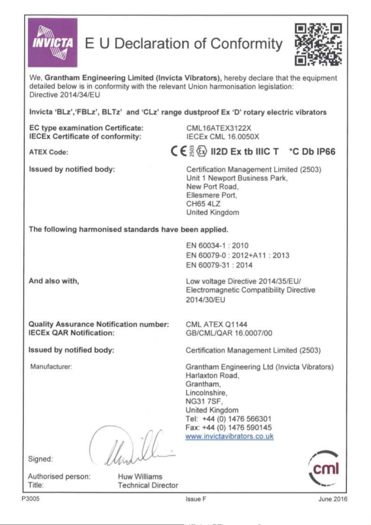
1) The vibrator is approved to the following certification:
ATEX Directive 2014/34/EU
Certificate Numbers CML16ATEX3122X and IECEx CML 16.0050X
ATEX Coding/marking II2D Ex tb IIIC T___° C Db IP66
HAZARDOUS AREA CLASSIFICATION;
Zone of Use (Dust) Zone 21 & 22
Rated Temperature Refer to tables on pages 4 & 5
Ingression Protection (BSEN60529) Main Enclosure IP66
Terminal Box IP66
The equipment is certified for use in ambient temperatures -20°C to +40°C.
The X in our certificate number signifies a special condition of use and applies to vibrators mounted in
orientations other than with a horizontal shaft and also those intended for use with variable speed drives;
i. The user is advised that this equipment is fitted with thermistors, RTDs or thermostats. Mounting the motor in any
orientation, other than with the shaft horizontal, requires the thermistors, RTDs or thermostats to be connected to a
suitable controlling and regulating device, as defined in article 1(b) of European Directive 2014/34/EU, and when
located in hazardous area , shall be covered by an appropriate EC or EU Type Examination Certificate.
This condition does not apply to the smaller vibrators in the Invicta range from BLz03 up to BLz25, fitted with ball
bearings.
ii. The user is advised that this equipment is fitted with thermistors, RTDs or thermostats, therefore, when a vibrator
mounted in any orientation is fed from a variable speed drive, it shall be connected to a suitable controlling and
regulating device, as defined in article 1(b) of European Directive 2014/34/EU, and when located in hazardous
areas, shall be covered by an appropriate EC or EU Type Examination Certificate.
iii. Where the vibrator is installed into a fixed installation where the installation is intended to minimise the risk from
electrostatic discharge the installer must ensure the vibrator is suitably earthed. The vibrator should not be operated
without a suitable earth in place. Regular checks as part of routine inspections should establish that the earth is
intact.
iv. The user shall mark the vibrator with information relevant to the chosen Variable Speed Control as detailed in BS
EN60079-0, clause 29.15.
2) The equipment has not been assessed as a safety related device (as referred to by directive 2014/34/EU Annex II,
clause 1.5).
3) Installation of this equipment shall be carried out by suitably trained personnel in accordance with the applicable
Code of Practice (EN60079-14).
4) Inspection and maintenance of this equipment shall be carried out by suitably trained personnel in accordance with
the applicable Code of Practice (EN60079-17).
Repair of this equipment shall be carried out by suitable trained personnel in accordance with the applicable Code of
Practice (EN60079-19).
The manufacturer offers a full repair service.
5) Components to be incorporated into or used as replacements in the equipment shall be fitted by suitably trained
personnel in accordance with the manufacturer's documentation.
Page 1

6) If the equipment is likely to come into contact with aggressive substances, then it is the responsibility of the user to
take suitable precautions to prevent it from being adversely affected, thus ensuring that the type of protection is not
compromised.
a) Aggressive Substances: e.g. acidic liquids or gases that may attack metals or solvents that may affect
polymeric materials (such as seals)
b) Suitable Precautions: e.g. regular checks as part of routine inspections or establishing from material
data sheet that it is resistant to specific chemicals.
7) Some Invicta vibrators are provided with either an integral cast lifting point or provision for the use of eye bolts. Users
are to ensure that shackles, eye bolts or any other required lifting equipment used are sufficiently rated to safely lift the
weight of the vibrator. The weight of each vibrator is included in the information stamped on the vibrator nameplate.
Users should also ensure that any lifting accessories or equipment is used in accordance with the manufacturer’s
instructions and the user’s codes of practice. The lifting points should be inspected for defects prior to each lifting
operation.
Note: The lifting points are designed solely to lift the vibrator only. Users should not, under any circumstance, use the
lifting point on the vibrator to lift any other plant or machinery that the vibrator may be mounted to.
WARNING: The shaft assembly inside the vibrator contains eccentric weights and is free to rotate as the
vibrator is lifted.
This potential shifting of the weight distribution should be taken into account when lifting the vibrator into
position.
Disclaimer
Invicta Vibrators are certified to comply with the European Directive 2014/34/EU (ATEX Directive) as described. It
remains the responsibility of the user to ensure that the equipment is correctly selected and rated for the environment in
which it is to be used in accordance with European Directive 99/92/EC (also known as ATEX 137 or the ATEX Workplace
Directive) and regulations 7 and 11 of the Dangerous Substances and Explosive Atmospheres Regulations 2002
(DSEAR).
Important Safety Note:
It is the responsibility of the intended user of the BLz vibrator to ensure that the installation and usage instructions
contained in this manual are fully understood before any attempt to install or use the vibrator is made. Failure to
understand and adhere to these instructions could result in fire, electric shock, explosion or serious personal injury.
This manual should be retained throughout the life of the vibrator and referred to whenever necessary.
Page 2
Page 3

Vibrator
Type
Power
Output
(Watts)
Surface Temperature
Max in +40ºC ambient
at Full Power
(°C)
Temperature Rating
Of Thermistors
(oC)
Cable Entry
Thread Size
BLz03-1/2
120
93
80
M16x1.5-6H
BLz03-0.5/4
100
106
90
M16x1.5-6H
BLz03-0.2/6
70
93
80
M16x1.5-6H
BLz03-0.3/6
70
93
80
M16x1.5-6H
BLz05-2/2
200
142
100
M20x1.5-6H
BLz05-1/4
175
106
90
M20x1.5-6H
BLz05-2/4
175
106
90
M20x1.5-6H
BLz05-0.4/6
90
119
100
M20x1.5-6H
BLz05-0.6/6
90
119
100
M20x1.5-6H
BLz05-0.9/6
90
119
100
M20x1.5-6H
BLz05-1.3/6
90
119
100
M20x1.5-6H
BLz15-3.5/2
300
131
100
M20x1.5-6H
BLz15-3/4
300
111
100
M20x1.5-6H
BLz15-1.3/6
110
121
100
M20x1.5-6H
BLz15-1.9/6
110
121
100
M20x1.5-6H
BLz20-5/2
400
130
100
M20x1.5-6H
BLz20-5/4
350
121
100
M20x1.5-6H
BLz20-2.2/6
150
112
100
M20x1.5-6H
BLz22-5/2
400
130
100
M20x1.5-6H
BLz22-5/4
350
121
100
M20x1.5-6H
BLz22-2.2/6
150
112
100
M20x1.5-6H
BLz24-8/2
500
130
120
M20x1.5-6H
BLz24-10/2
500
130
120
M20x1.5-6H
BLz24-13/2
500
130
120
M20x1.5-6H
BLz24-7.5/4
500
130
120
M20x1.5-6H
BLz24-11/4
500
130
120
M20x1.5-6H
BLz24-14/4
500
130
120
M20x1.5-6H
BLz24-4/6
510
130
120
M20x1.5-6H
BLz24-8/6
510
130
120
M20x1.5-6H
BLz24-11/6
510
130
120
M20x1.5-6H
BLz25-8/2
500
130
120
M20x1.5-6H
BLz25-10/2
500
130
120
M20x1.5-6H
BLz25-13/2
500
130
120
M20x1.5-6H
BLz25-7.5/4
500
130
120
M20x1.5-6H
BLz25-11/4
500
130
120
M20x1.5-6H
BLz25-14/4
500
130
120
M20x1.5-6H
510
130
120
M20x1.5-6H
BLz25-8/6
510
130
120
M20x1.5-6H
BLz25-11/6
510
130
120
M20x1.5-6H
BLz30-16/2
1100
130
120
M20x1.5-6H
BLz30-20/2
1100
130
120
M20x1.5-6H
BLz30-18/4
1150
130
120
M20x1.5-6H
BLz30-25/4
1150
130
120
M20x1.5-6H
BLz30-14/6
900
135
120
M20x1.5-6H
BLz30-18/6
900
135
120
M20x1.5-6H
BLz30-23/6
900
135
120
M20x1.5-6H
BLz30-7.5/8
500
129
110
M20x1.5-6H
BLz30-10/8
500
129
110
M20x1.5-6H
FULL POWER TEST DATA AND TEMPERATURE RATINGS
L SERIES VIBRATORS TO EN 60079-31
Page 4

Vibrator
Type
Power
Output
(Watts)
Surface Temperature
Max in +40ºC ambient
at Full Power
(°C)
Temperature Rating
Of Thermistors
(oC)
Cable Entry
Thread Size
BLz40-30/2
1500
133
120
M20x1.5-6H
BLz40-40/2
1500
133
120
M20x1.5-6H
BLz40-35/4
1800
114
100
M20x1.5-6H
BLz40-27/6
1800
124
110
M20x1.5-6H
BLz40-35/6
1800
124
110
M20x1.5-6H
BLz40-15/8
1100
132
120
M20x1.5-6H
BLz40-17/8
1100
132
120
M20x1.5-6H
BLz45-50/2
4000
130
120
M25x1.5-6H
BLz45-45/4
2685
130
120
M25x1.5-6H
BLz45-42/6
2310
134
120
M25x1.5-6H
BLz45-50/6
2310
134
120
M25x1.5-6H
BLz45-24/8
2000
130
120
M25x1.5-6H
BLz45-35/8
2000
130
120
M25x1.5-6H
BLz50-55/4
3350
130
120
M25x1.5-6H
BLz50-65/4
4800
130
120
M25x1.5-6H
BLz50-75/4
4800
130
120
M25x1.5-6H
BLz50-60/6
4000
122
110
M25x1.5-6H
BLz50-75/6
4000
122
110
M25x1.5-6H
BLz50-35/8
3300
100
90
M25x1.5-6H
BLz50-45/8
3300
100
90
M25x1.5-6H
BLz50-55/8
3300
100
90
M25x1.5-6H
BLz50-57/8
3300
100
90
M25x1.5-6H
BLz60-95/4
7750
130
120
M32x1.5-6H
BLz60-105/4
7750
130
120
M32x1.5-6H
BLz61-105/4
7750
130
120
M32x1.5-6H
BLz60-90/6
6200
130
120
M32x1.5-6H
BLz60-105/6
6200
130
120
M32x1.5-6H
BLz61-105/6
6200
130
120
M32x1.5-6H
BLz60-125/6
10000
130
120
M32x1.5-6H
BLz61-125/6
10000
130
120
M32x1.5-6H
BLz60-65/8
4900
117
100
M32x1.5-6H
BLz60-70/8
4900
117
100
M32x1.5-6H
BLz60-90/8
4900
117
100
M32x1.5-6H
BLz75-130/4
10250
130
120
M32x1.5-6H
BLz75-150/6
10000
130
120
M32x1.5-6H
BLz78-165/6
10000
130
120
M32x1.5-6H
BLz75-185/6
10000
130
120
M32x1.5-6H
BLz77/78-185/6
10000
130
120
M32x1.5-6H
BLz77-124/8
7750
125
110
M32x1.5-6H
BLz75-150/8
7750
125
110
M32x1.5-6H
BLz75-200/8
7750
125
110
M32x1.5-6H
BLz77-200/8
BLz80 230/6
BLz80 270/6
BLz80-205/8
7750
12500
12500
9700
125
160
160
160
110
150
150
150
M32x1.5-6H
M32x1.5-6H
M32x1.5-6H
M32x1.5-6H
Note: Cable gland temperature can exceed +70°C
FULL POWER TEST DATA AND TEMPERATURE RATINGS
L SERIES VIBRATORS TO EN 60079-31
Page 5

BEARING REPLACEMENT – IMPORTANT NOTICE
To satisfy EN13463 Part 5 Clause 6.1 & 6.2 the bearings in this equipment shall be replaced after a period not exceeding 90% of their
rated life. The user’s attention is therefore drawn to the list of bearing lives shown in the table below.
L 10 BEARING FATIGUE LIFE L SERIES DUST PROTECTED VIBRATORS TO EN60079-31
Frame Size Centrifugal Force Fatigue life (Hours) L10
Kg Newtons Bearing Types 50 Hz 90% 60 Hz 90%
Vibrators at 2880/3456 RPM
BLz 03-1/2 100 981 6301 2Z C3 49940 44950 41400 37260
BLz 05-2/2 200 1962 6304 2Z C3 28000 25200 23230 20900
BLz 15-3.5/2 350 3433 6306 2Z C3 25380 22840 21150 19035
BLz 20/22-5/2 500 4905 6308 2Z C3 29700 26730 24670 22200
BLz 24/25-8/2 800 7848 6309 2Z C3 15380 13840 12780 11500
BLz 24/25-10/2 1000 9810 NJ 2306E TVP2 C3 49050 44150 40720 36650
BLz 24/25-13/2 1300 12753 NJ 2307E TVP2 C3 41560 37400 34490 31040
BLz 30-16/2 1600 15695 NJ 2309E TVP2 C3 82540 74290 68500 61650
BLz 30-20/2 2000 19620 NJ 2309E TVP2 C3 39260 35330 32580 29320
BLz 40-30/2 3000 29430 NJ 2311E TVP2 C3 35500 31950 29460 26510
BLz 40-40/2 4000 39240 NJ 2313E TVP2 C3 28860 25970 23950 21550
BLz 45-50/2 5000 49050 NJ 2312E TVP2 C4 12343 11110 10286 9260
Vibrators at 1440/1728 RPM
BLz 03-0.5/4 50 490 6301 2Z C3 >100000 90000 85470 76920
BLz 05-1/4 100 981 6304 2Z C3 >100000 90000 >100000 90000
BLz 05-2/4 200 1962 6304 2Z C3 24640 22180 20530 18480
BLz 15-3/4 300 2943 6305 2Z C3 40560 36500 33800 30420
BLz 20/22-5/4 500 4905 6307 2Z C3 28710 25840 23930 21540
BLz 24/25-7.5/4 750 7357 6309 2Z C3 37510 33760 31130 28020
BLz 24/25-11/4 1100 10790 NJ 2306E TVP2 C3 70710 63640 58670 52800
BLz 24/25-14/4 1400 13735 NJ 2307E TVP2 C3 65650 59080 53640 48280
BLz 30-18/4 1800 17658 NJ 2309E TVP2 C3 >100000 90000 91960 82760
BLz 30-25/4 2500 24525 NJ 2309E TVP2 C3 37080 33370 30770 27690
BLz 40-35/4 3500 34335 NJ 2311E TVP2 C3 42340 38100 35130 31620
BLz 45-45/4 4500 44145 NJ 2313E TVP2 C3 38390 34550 31850 28660
BLz 50-55/4 5500 53955 NJ 2315E TVP2 C3 49060 44150 40710 36640
BLz 50-65/4 6500 63765 NJ 2317E M1A C3 42800 38520 35500 31950
BLz 50-75/4 7500 73575 NJ 2317E M1A C3 32040 28830 26580 23920
BLz 60-95/4 9500 93195 NJ2320E M1A C3 52820 47540 43820 39440
BLz60/61-105/4 10500 103000 NJ2320E M1A C3 37700 33930 31410 28270
BLz 75-130/4 13000 127530 NJ 2322E M1A C3 31320 28190 25980 23380
Vibrators at 960/1152 RPM
BLz 03-0.2/6 22 216 6301 2Z C3 > 100000 90000
BLz 03-0.3/6 32 314 6301 2Z C3 > 100000 90000
BLz 05-0.4/6 40 392 6304 2Z C3 > 100000 90000
BLz 05-0.6/6 60 589 6304 2Z C3 > 100000 90000
BLz 05-0.9/6 90 883 6304 2Z C3 > 100000 90000
BLz 05-1.3/6 130 1275 6304 2Z C3 >100000 90000
BLz 15-1.3/6 130 1275 6305 2Z C3 > 100000 90000
BLz 15-1.9/6 190 1864 6305 2Z C3 >100000 90000
BLz 20/22-2.2/6 220 2158 6307 2Z C3 > 100000 90000 >100000 90000
BLz 24/25-4/6 440 3924 6309 2Z C3 > 100000 90000 >100000 90000
BLz 24/25-8/6 800 7848 NJ 2306E TVP2 C3 > 100000 90000 >100000 90000
BLz 24/25-11/6 1100 10790 NJ 2307E TVP2 C3 > 100000 90000 >100000 90000
BLz 30-14/6 1400 13734 NJ 2309E TVP2 C3 > 100000 90000 >100000 90000
BLz 30-18/6 1800 17658 NJ 2309E TVP2 C3 > 100000 90000 >100000 90000
BLz 30-23/6 2300 22563 NJ 2309E TVP2 C3 60000 54000 50000 45000
BLz 40-27/6 2700 26487 NJ 2311E TVP2 C3 > 100000 90000 >100000 90000
BLz 40-35/6 3500 34335 NJ 2311E TVP2 C3 63300 56970 52700 47430
BLz 45-42/6 4200 41200 NJ 2313E TVP2 C3 69980 62980 58070 52260
BLz 45-50/6 5000 49050 NJ 2313E TVP2 C3 40400 36360 33670 30300
BLz 50-60/6 6000 58860 NJ 2315E TVP2 C3 55120 49610 45740 41170
BLz 50-75/6 7500 73575 NJ 2317E TVP2 C3 4 8200 43380 40000 36000
BLz 60-90/6 9000 88290 NJ 2320E TVP2 C3 94510 85060 78760 70880
BLz 60/61-105/6 10500 103000 NJ 2320E TVP2 C3 57430 51690 47300 42570
BLz 60/61-125/6 12500 122625 NJ 2320E TVP2 C3 29150 26235 24290 21860
BLz 75-150/6 15000 147500 NJ 2322E M1A C3 29260 26330 24280 21850
BLz 78-165/6 16500 161865 NJ 2322E M1A C3 21140 19025 17610 15850
BLz 75/77/78-185/6 18500 181485 NJ 2322E M1A C3 14440 13000 12030 10830
BLz 80-230/6 23000 225630 NJ2326E M1 C3 30190 27170 25160 22645
BLz 80-270/6 27000 264880 NJ2326E M1 C3 17700 15930 14750 13275
Page 6

L 10 BEARING FATIGUE LIFE L SERIES DUST PROTECTED VIBRATORS TO EN60079-31
Frame Size Centrifugal Force Fatigue life (Hours) L10
Kg Newtons Bearing Types 50 Hz 90% 60 Hz 90%
Vibrators at 720/864 RPM
BLz 30-7.5/8 750 7357 NJ 2309E TVP2 C3 >100000 90000 >100000 90000
BLz 30-10/8 1000 9810 NJ 2309E TVP2 C3 >100000 90000 >100000 90000
BLz 40-15/8 1500 14715 NJ 2311E TVP2 C3 >100000 90000 -- -BLz 40-17/8 1700 16671 NJ 2311E TVP2 C3 -- >100000 90000
BLz 45-24/8 2430 23838 NJ 2313E TVP2 C3 >100000 90000 >100000 90000
BLz 45-35/8 3500 34335 NJ 2313E TVP2 C3 -- >100000 90000
BLz 50-35/8 3500 34335 NJ 2315E TVP2 C3 >100000 90000 -- -BLz 50-45/8 4500 44145 NJ 2315E TVP2 C3 >100000 90000 >100000 90000
BLz 50-55/8 5500 53955 NJ 2317E TVP2 C3 >100000 90000 -- -BLz 50-57/8 5700 55917 NJ 2317E TVP2 C3 -- >100000 90000
BLz 60-65/8 6500 63765 NJ 2320E TVP2 C3 >100000 90000 -- -BLz 60-70/8 7000 68670 NJ 2320E TVP2 C3 -- >100000 90000
BLz 60-90/8 9000 88290 NJ 2320E TVP2 C3 >100000 90000 >100000 90000
BLz 75/77-124/8 12400 121644 NJ 2322E M1A C3 68370 61530 56970 51270
BLz 75-135/8 13500 132435 NJ 2322E M1A C3 55020 49520 -- -BLz 75-150/8 15000 147150 NJ 2322E M1A C3 38960 35060 32330 29100
BLz 75/77-200/8 20000 196200 NJ 2322E M1A C3 -- -- 12455 11210
BLz 80-205/8 20500 201105 NJ2326E M1 C3 59050 53145 49205 44285
Page 7
Size
Torque (N.m)
Size
Torque (N.m)
Cap-Screws
Grade 12.9
Setscrews/Bolts
Grade 8.8
Cap-Screws
Grade 12.9
Setscrews/Bolts
Grade 8.8
M 5 8 -
M 16
310
242
M 6
15
11
M 20
580
473
M 8
34
27
M 24
950
818
M 10
68
56
M 30
-
1634*
M 12
127
96
M 36
-
2854*
Use the above figures for all screws except out of balance weights. (see page 29)
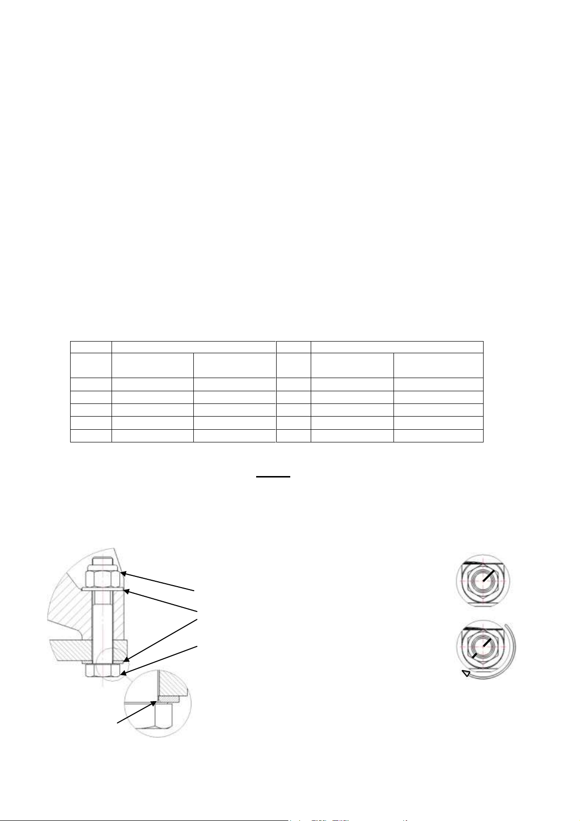
FIG.2
FIG.3
FIG.1
Washer Chamfer
this side.
‘L’ SERIES VIBRATOR INSTALLATION AND MAINTENANCE
RECEIPT AND STORAGE
Each vibrator is tested and inspected on completion. Whilst every care is taken during transit they should be
inspected on receipt and any defects immediately reported to the carrier and supplier. When not for immediate
use, they can be stored for up to two years if kept in a clean, dry and temperate atmosphere, free from
vibration. After more than 2 years of storage the bearing grease should be replaced before the motor is used.
INSTALLATION GUIDANCE NOTES:
Mechanical: Inspect vibrator for any physical damage and check that rotor shaft rotates freely. Remove paint
masking stickers from motor mounting holes. ALL mounting surfaces MUST be flat and free of paint, dirt and
scale. Fixing bolts should be tightened as recommended below and tightness checked after initially running
the vibrator. Bolts and nuts should not be reused. Please ensure there is at least 50mm of clearance between
the vibrator and any surrounding static structure.
IMPORTANT - GAPS BETWEEN THE VIBRATOR FOOT AND MATING SURFACES AND INCORRECT
BOLT TIGHTNESS WILL CAUSE BOLT BREAKAGE AND DAMAGE TO THE VIBRATOR.
Fixing bolt tightening: Use Grade 8.8 bolts with Grade 8 self locking nuts, torqued to values below. Figures
below apply to un-plated dry threads.
Where capscrews are used with locking nuts, Grade 10 nuts must be fitted.
Use plain washers for BLz 03 - BLz 24 (aluminium frames) Not BLz22. If washers are used for BLz22 - BLz80
(cast iron frames) Not BLz24, hardened washers (PSN 612 to DIN 6916 or BS EN 14399-6) must be fitted.
BLz 75 - 80: Half turn method.
In exceptional circumstances where tooling is not available, the half turn method may be used.
PSN 661 – High Strength nut
PSN 612 – Hardened washer under
bolt head and nut
PSN 780 - High strength bolt
Remove any paint, dirt or scale from all mating surfaces.
Fit hardened washer (PSN 612) under bolt head and nut. Pre-tighten until all mating surfaces are in contact.
Mark nuts and bolts as shown in fig. 2 and slog nut one half turn until marks are as shown in fig. 3.
Page 8

Delta
Star Y
Group 01
230v 50 Hz & 60 Hz
380 - 415v 50 Hz, 460 - 480v 60Hz
Group 03
500v 50Hz, 575v 60Hz
Group 07 380v 60Hz
Group 28
400v 50Hz
690v 50Hz
Nut size
Tightening torque
(Nm)
M4
1.1
M5
2.2
M6
3.7
Electrical
Check insulation resistance and if less than 1 megohm DO NOT USE, consult a qualified electrician. Perform
a continuity resistance check between the external earth point and end covers, terminal box lid and nameplate,
if the resistance is more than 1.0 ohms between the earth point and any of the aforementioned items, DO NOT
USE, consult a qualified electrician. Note: this continuity check should be performed after each removal and
re-fitting of the end cover and terminal box lid.
A flexible cable and suitable cable gland must be used to connect between the vibrator and supply junction
box.
The cable gland shall comply with EN60079-0 and have an IP rating equal to or better than IP66 (see table on
pages 4 & 5 for cable entry thread sizes). The supply must be suitably fuse protected. 4 core cable to be
used with flexible conductors type; 24/0.20 (BLz 03); 50/0.25 (BLz 05 – BLz 40); 56/0.30 (BLz 45 – BLz 50);
80/0.40 (BLz 60/61 – BLz 75-80): BLz 24 to BLz 80 are fitted with thermistors as standard and require a 2
core cable with flexible conductors type 30/0.25. The external earth cable must have a cross sectional area of
at least 4mm²
Flexible conductors must be terminated with insulated crimp on ring terminals, or ring terminals fitted with
insulating sleeves for L1, L2, L3 and earth. Plain soldered ends for thermistor connections T1 and T2.
If thermistors are not required leave the blanking plug in the cable entry hole.
BLz Vibrators are suitable for a 3 phase 50Hz or 3 phase 60Hz electrical supply. BLz vibrators are
rated for continuous duty. The insulation class of the winding will be either ‘F’ or ‘H’ as indicated on
the nameplate. Starting can be direct on line via inverter or soft start. Each vibrator MUST BE
INDIVIDUALLY PROTECTED against overload. Each overload should be of the delayed magnetic-circuit
breaker type to prevent tripping during the high starting current requirement of vibrator starting. The overload
size should be selected based on the full load current and starting current values listed on pages 11 & 12.
NOTE When operating vibrators at speeds above pole speed the out of balance force MUST be reduced or
DAMAGE WILL OCCUR; see Page 30 for correct percentage reduction.
VOLTAGE RANGE
The voltage range data on pages 11 & 12 (230-690v 50Hz and 230-575v 60Hz) is served by four distinct
windings* thus:
* Except BLz40 8 Pole which uses group 43 windings for 460-480v 60Hz.
The winding group number and Hertz appears in the vibrator designation and on the nameplate Thus a BL25-
14/4 400v 50Hz machine will be designated BL25-14/4/01/50.
It is essential that the correct Winding (group) is used with the specified electrical supply. Noncompliance with the above instructions will result in electrical failure.
Terminal post nuts should be tightened to the values given in the table below.
Page 9
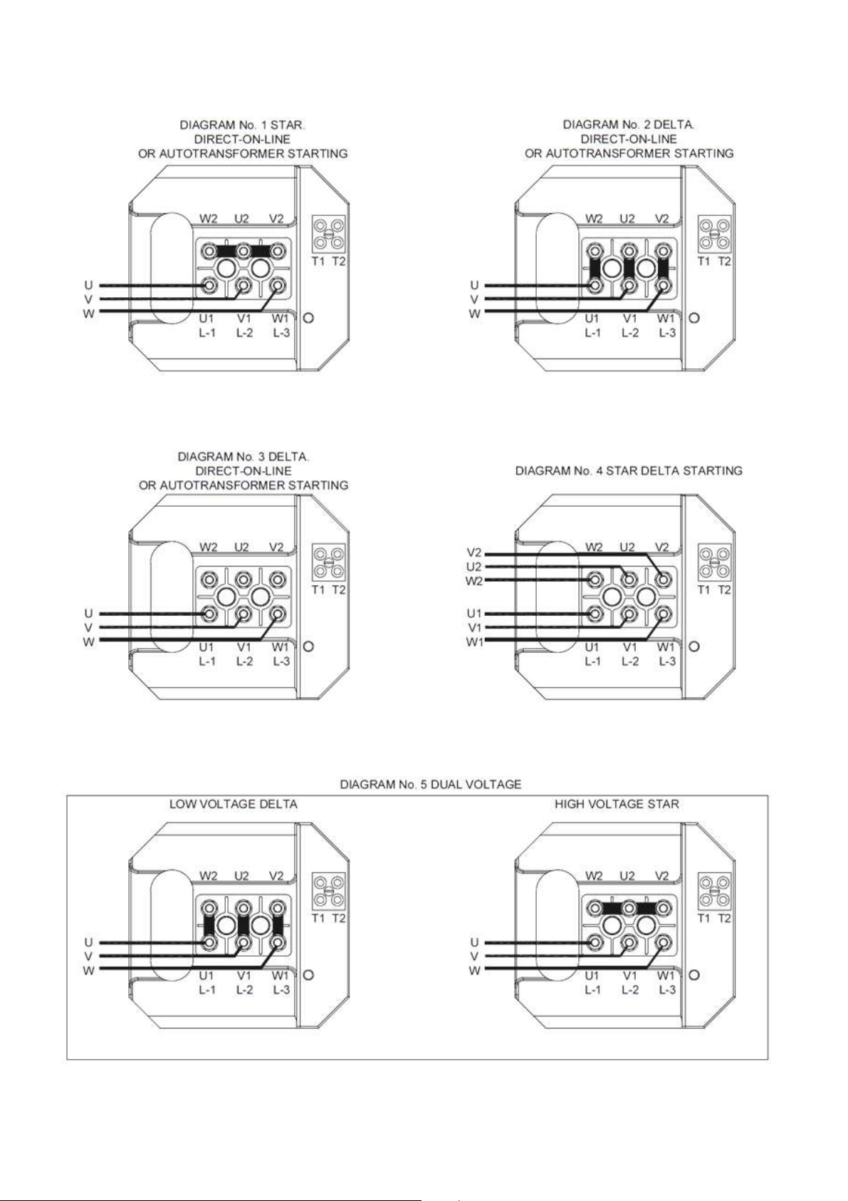
VIBRATOR TERMINAL BOX field connection 3 Phase, 50/60 Hertz
The installer is directed to the diagram number engraved on the nameplate for the appropriate field connection
diagram (below).
Refer to nameplate for required connection.
L1 - L3 are line connections. T1 & T2 are thermistor connections.
Page 10

01**
Y 01*
Y 01*
Y 03*
28**
Y 28*
Type
Output
230 Volts
50 Hz
380 Volts
50 Hz
400 Volts
50 Hz
500 Volts
50 Hz
400 Volts
50 Hz
690 Volts
50 Hz
Watts
FLC
SC
FLC
SC
FLC
SC
FLC
SC
FLC
SC
FLC
SC
2 POLE - 2880 RPM
BLz 03
120
0.33
2.7
0.18
1.6
0.19
1.6
0.16
1.2
0.2
1.7
0.12
1.0
BLz 05
200
0.60
5.2
0.34
3.1
0.35
3.0
0.27
2.4
0.58
5.0
0.33
2.8
BLz 15
300
0.98
5.2
0.58
3.1
0.56
3.0
0.46
2.4
0.58
5.0
0.33
2.8
BLz 20/22
400
1.35
9.8
0.79
5.9
0.78
5.6
0.64
4.5
0.81
5.8
0.47
3.4
BLz 24/25
500
2.03
17.8
1.19
10.8
1.17
10.2
0.98
8.2
1.22
10.6
0.70
7.4
BLz 30
1100
3.6
27
2.2
16
2.1
16
1.7
13
BLz 40
1500
5.0
48
3.0
29
2.9
28
2.3
22
2.9
35
1.7
21
BLz 45
4000
12.7
89
7.6
53
7.3
51
5.8
41
4 POLE - 1440 RPM
BLz 03
100
0.34
1.4
0.19
0.9
0.20
0.8
0.17
0.7
BLz 05
175
0.71
2.9
0.41
1.7
0.41
1.7
0.35
1.3
BLz 15
300
1.24
4.0
0.71
2.4
0.71
2.3
0.60
1.9
0.75
2.4
0.44
1.4
BLz 20/22
350
1.68
6.3
0.95
3.8
0.97
3.6
0.81
2.9
1.03
3.8
0.60
2.2
BLz 24/25
500
2.28
15.1
1.34
9.2
1.32
8.7
1.14
7.0
1.43
9.4
0.83
5.5
BLz 30
1150
4.3
42
2.5
25
2.5
24
2.1
19
2.62
25
1.51
14.5
BLz 40
1800
6.4
56
3.8
34
3.7
32
3.1
26
3.86
33
2.23
19.3
BLz 45
2685
9.2
83
5.4
49
5.3
48
4.5
41
5.5
59
3.2
34.3
BLz 50-55
3350
11
109
6.5
65
6.4
64
5.3
53
6.6
66
3.8
38
BLz 50-65, 75
4800
14.9
137
8.8
81
8.6
79
7.1
65
8.8
90
5.1
52
BLz60/61
7750
22.3
241
13.4
145
12.9
140
10.4
113
13.1
193
7.6
112
BLz 75
10250
28.9
200
17.4
120
16.7
115
13.5
93 6 POLE - 960 RPM
BLz 03
70
0.8
0.87
0.47
0.48
0.46
0.5
0.38
0.43
BLz 05
90
0.94
1.56
0.53
0.87
0.54
0.9
0.46
0.55
BLz 15
110
1.03
1.55
0.59
0.85
0.6
0.9
0.5
0.78
BLz 20/22
150
1.55
2.78
0.87
1.53
0.9
1.60
0.76
2.0
BLz 24/25
510
2.79
12.2
1.58
7.4
1.61
7.0
1.33
5.6
1.7
7.4
0.99
4.3
BLz 30
900
5.2
26
2.9
16
3.0
15
2.5
12
3.2
16
1.85
9.3
BLz 40
1800
8.7
43
4.9
26
5.0
25
4.3
20
5.4
27
3.1
15.6
BLz 45
2310
11.0
76
6.2
46
6.3
44
5.5
35
6.9
49
4.0
28
BLz 50
4000
15.2
106
8.7
64
8.8
61
7.4
49
9.3
64
5.3
37
BLz 60/61-90,105
6200
19.4
188
11.4
114
11.2
108
9.5
86
11.6
112
6.7
64
BLz 60/61-125
10000
31.2
222
18.4
131
18.0
128
14.8
105
18.3
233
10.5
135
BLz 75/77/78
10000
31.2
222
18.4
131
18.0
128
14.8
105
18.3
233
10.5
135
BLz80
12500
44
266
26.6
161
25.3
153
20.2
122 8 POLE - 720 RPM
BLz 30
500
4.0
18
2.2
11
2.3
10.4
2.0 8 BLz 40
1100
6.2
23
3.5
14
3.6
13.5
3.1
11
BLz 45
2000
10.6
40
5.9
24
6.1
23
5.3
18
BLz 50
3300
15.0
96
8.4
58
8.6
55
7.6
44
BLz 60
4900
23.0
170
12.9
103
13.3
97
11.8
78
14.4
106
8.3
62
BLz 75 /77
7750
34.8
216
19.9
130
20.1
124
17.4
99
20.6
126
11.9
71
BLz80
9700
40.7
237
23.8
138
23.6
137
See Voltage Range note & also connection diagrams on pages 9 & 10.
See Voltage Range note & also connection diagrams on pages 9 & 10.
See Voltage Range note & also connection diagrams on pages 9 & 10.
See Voltage Range note & also connection diagrams on pages 9 & 10.
FULL LOAD AND STARTING CURRENTS IN AMPS FOR BLz SERIES VIBRATORS (Winding groups 01, 03 & 28)
Maximum Figures for +40oC Ambient
*STAR = Y **Delta =
Page 11
 Loading...