

Invacare top end terminator series, Top End Terminator Titanium, Top End Terminator Everyday User Manual
TopEnd®Terminator™Series
TerminatorTitanium,TerminatorwithHeavyDuty
Option,TerminatorEveryday
ENWheelchairs
UserManual
ThismanualMUSTbegiventotheuseroftheproduct.
BEFOREusingthisproduct,readthismanualandsaveforfuturereference.

©2013Invacare®Corporation
Allrightsreserved.Republication,duplicationormodificationinwholeorinpartisprohibitedwithout
priorwrittenpermissionfromInvacare.Trademarksareidentifiedby™and®.Alltrademarksare
ownedbyorlicensedtoInvacareCorporationoritssubsidiariesunlessotherwisenoted.
3-in-1oilisaregisteredtrademarkofAmericanHomeProductsCorporation.
Loctite242isatrademarkoftheLoctiteCorporation.
TeflonisaregisteredtrademarkofE.I.DuPontDeNemoursandCompany
PhillipsisaregisteredtrademarkofthePhillipsScrewCompany.
WD-40isaregisteredtrademarkofWD-40Company.
PleaserecordyourserialnumberSN#_________________.
TheSNisrequiredforanywarrantyclaimsandplacingaftermarketpartsorders.

Contents
1General......................................5
1.1Symbols..................................5
1.2IntendedUse..............................5
1.3ServiceLife...............................5
1.4Dealer/TechnicianInformation.................5
2Safety........................................6
2.1GeneralGuidelines..........................6
2.2StabilityWarning...........................7
2.3OperatingInformation.......................8
2.4WeightCapacity...........................10
2.5CopingwithEverydayObstacles................10
2.6ANotetoWheelchairAssistants...............10
2.7WeightDistribution.........................11
2.8Reaching,LeaningandBending.................12
2.9Tipping..................................13
2.10Stairways.................................14
2.11TransferringToandFromOtherSeats...........14
2.12SafetyInspectionChecklist....................15
3Overview.....................................17
3.1LabelLocationsandComponentIdentification......17
3.2TypicalProductParameters...................18
3.3TirePressureConversion.....................23
4Operation....................................24
4.1Unfolding/FoldingtheBack....................24
4.2BackAngleAdjustment......................25
4.3AdjustableTensionBackUpholstery.............29
ReplacingAdjustableTensionBack
Upholstery..............................29
4.4BackHeightAdjustment(AdjustableBack
Only)...................................31
4.5AdjustingtheT-Arms........................32
4.6AdjustingT-ArmSockets.....................33
4.7AdjustingQuick-ReleaseAxles.................34
4.8AdjustingQuad-ReleaseHandles................35
4.9RemovingPlayfromRearWheels...............35
4.10Opening/ClosingCamberClamps...............35
4.11AdjustingRearWheelCamber.................37
4.12DeterminingToeIn/ToeOut..................37
4.13AdjustingToeIn/ToeOut.....................39
4.14AdjustingWheelbaseLength(Centerof
Gravity)..................................41
4.15AdjustingWheelbaseWidth...................42
4.16AdjustingtheAxleTube......................43
4.17Adjusting/ReplacingFootrest...................46
4.18Adjusting/ReplacingAnti-Tipper................46
5Service.......................................48
5.1Removing/InstallingFoldoverBackUpholstery......48
5.2InstallingtheSwingawayPaddedArmrest
Socket...................................48
5.3Installing/Removing/AdjustingtheSwingaway
PaddedArmrest............................50
5.4InstallingtheT-ArmSockets...................50
5.5Installing/RemovingT-Arms...................51
5.6ReplacingT-ArmLockingLever................51
5.7Removing/InstallingRearWheels................52
5.8HandrimReplacement.......................53
5.9Repairing/ReplacingRearWheelTire/Tube........54
5.10ReplacingQuad-ReleaseAxles.................54
5.11ReplacingAxleTube.........................55
5.12Replacing/AdjustingCasters...................57
5.13WheelLockAdjustment/Replacement............57

5.14ReplacingAdjustableTensionSeatUpholstery......59
5.15ReplacingScrew-OnSeatUpholstery.............60
5.16Replacing/AdjustingOptionalAdjustableAngle
Footrest.................................60
5.17Installing/Removing/AdjustingSwivelAnti-Tip.......61
5.18ElastomersandSuspension....................62
6Troubleshooting...............................64
6.1Troubleshooting...........................64
7Maintenance..................................65
7.1Maintenance..............................65
8Options......................................66
8.1Options..................................66
9Warranty.....................................69
9.1WarrantyInformation.......................69
9.2European,Australian,andNewZealandLimited
WarrantyInformationandCustomerService.......71

General
1General
1.1Symbols
Signalwordsareusedinthismanualandapplytohazardsorunsafe
practiceswhichcouldresultinpersonalinjuryorpropertydamage.
Seetheinformationbelowfordefinitionsofthesignalwords.
WARNING!
–Warningindicatesapotentiallyhazardoussituation
which,ifnotavoided,couldresultindeathorserious
injury.
CAUTION!
–Cautionindicatesapotentiallyhazardoussituation
which,ifnotavoided,mayresultinpropertydamage
orminorinjuryorboth.
–Indicatesahazardoussituationthatcouldresultin
damagetopropertyifitisnotavoided.
Givesusefultips,recommendationsandinformationfor
efficient,trouble-freeuse.
ThisproductcomplieswithDirective93/42/EEC
concerningmedicaldevices.
ThelaunchdateofthisproductisstatedintheEC
declarationofconformity.
1.2IntendedUse
Theintendeduseforthemanual(mechanical)wheelchairitto
providemobilityandtransportationofphysicallyimpairedpersons.
Themanualwheelchairisintendedforongoingdailyuse.Themodels
offerawiderangeofcustomizationwhichallowsforabetterfit
fortheenduserresultingincomfort,lightweight,easierpropelling,
transferring,andsmoothride.Themanualwheelchairisintendedfor
indoorandoutdooruseonfirmsurfacesfreeofclimbingobstacles.
Allotherusesareprohibited.
1.3ServiceLife
Theexpectedservicelifeofthisproductisfiveyearswhenuseddaily
andinaccordancewiththesafetyinstructions,maintenanceintervals
andcorrectuse,statedinthismanual.Theeffectiveservicelifecan
varyaccordingtofrequencyandintensityofuse.
1.4Dealer/TechnicianInformation
Theterm“qualifiedtechnician”inthismanualreferstoanInvacare
qualifiedtechnician.
1171801-A5

TopEnd
®
Terminator™Series
2Safety
2.1GeneralGuidelines
Thesafetysectioncontainsimportantinformationforthesafe
operationanduseofthisproduct.
WARNING!
–Donotusethisproductwithoutfirstcompletely
readingandunderstandingtheseinstructionsand
anyadditionalinstructionalmaterialsuchasowner’s
manuals,servicemanualsorinstructionsheets
suppliedwiththisproduct.Ifyouareunableto
understandthewarnings,cautionsorinstructions,
contactahealthcareprofessional,dealerortechnical
personnelbeforeattemptingtousethisequipmentotherwise,injuryordamagemayoccur.
–AQualifiedTechnicianMUSTperformtheinitialset
upofthiswheelchair.also,aqualifiedtechnicianmust
performallproceduresspecificallyindicatedinthe
manual.
WARNING!
ACCESSORIES
–Invacareproductsarespecificallydesignedand
manufacturedforuseinconjunctionwithInvacare
accessories.Accessoriesdesignedbyother
manufacturershavenotbeentestedbyInvacareand
arenotrecommendedforusewithInvacareproducts.
–THEINFORMATIONCONTAINEDINTHIS
DOCUMENTISSUBJECTTOCHANGEWITHOUT
NOTICE.
–Checkallpartsforshippingdamageandtestbefore
using.Incaseofdamage,doNOTuse.ContactTop
End/Carrierforfurtherinstruction.
61171801-A

Safety
2.2StabilityWarning
WARNING!
–Thepositionofthefootrest,cambertube,backangle,
thetautnessofthebackupholsteryaswellasthe
user’sconditionaredirectlyrelatedtothewheelchairs
stability.Anychangetooneoranycombinationofthe
fiveconditionsmaycausethewheelchairtodecrease
instability.
–Useextremecautionwhenusinganewseating
position.Theadditionofanti-tippersmayberequired.
Whenchangestothelefthandcolumnoccur,followacross
thechartandrefertotheprocedurethatischeckedto
maintaintheproperstability,safetyandhandlingofthe
wheelchair.
Checked=ü
FOOTREST
POSITION
CAMBERTUBEBACKANGLEBACK
UPHOLSTERY
USER
CONDITION
FOOTREST
POSITION
üüü
CAMBERTUBE
üüü
BACKANGLE
üüüü
BACKUPHOLSTERY
üüü
USERCONDITION
üüüüü
1171801-A7

TopEnd
®
Terminator™Series
2.3OperatingInformation
WARNING!
–Todetermineandestablishyourparticularsafety
limits,practicebending,reachingandtransferring
activitiesinseveralcombinationsinthepresenceof
aqualifiedhealthcareprofessionalbeforeattempting
activeuseofthewheelchair.
–DONOTattempttoreachobjectsifyouhaveto
moveforwardintheseat.
–DONOTattempttoreachobjectsifyouhavetopick
themupfromthefloorbyreachingdownbetween
yourknees.
–DONOTleanoverthetopofthebackupholstery
toreachobjectsfrombehindasthismaycausethe
wheelchairtotipover.
–DONOTshiftyourweightorsittingpositiontoward
thedirectionyouarereachingasthewheelchairmay
tipover.
–DONOTtipthewheelchairwithoutassistance.
–DONOTuseanescalatortomoveawheelchair
betweenfloors.Seriousbodilyinjurymayoccur.
Beforeattemptingtotransferinoroutofthe
wheelchair,everyprecautionshouldbetakento
reducethegapdistance.Turnbothcastersparallelto
theobjectyouaretransferringonto.Alsobecertain
thewheellocksareengagedtopreventthewheels
frommoving.
–DONOToperateonroads,streetsorhighways.
–DONOTclimb,goupordownrampsortraverse
slopesgreaterthan9°.
–DONOTattempttomoveupordownaninclinewith
awater,iceoroilfilm.
WARNING!
–DONOTattempttorideovercurbsorobstacles.
Doingsomaycauseyourwheelchairtoturnoverand
causebodilyharmordamagetothewheelchair.
–DONOTattempttoliftthewheelchairbyany
removable(detachable)parts.Liftingbymeansof
anyremovable(detachable)partsofawheelchair
mayresultininjurytotheuserordamagetothe
wheelchair.
–DONOTstandontheframeofthewheelchair.
–Checkallallenscrewsthatsecurethefootrest/raised
footrestsystemtothechairframebeforeusingthe
wheelchair,especiallyifengaginginanycontactsport.
–Anti-tippersMUSTBEattachedatalltimes.
Inasmuchastheanti-tippersareanoptiononthis
wheelchair(youmayorderwithorwithoutthe
anti-tippers),Invacarestronglyrecommendsordering
theanti-tippersasanadditionalsafeguardforthe
wheelchairuser.
–Anti-tippersMUSTbeusedatalltimes.When
outdoorsonwet,softgroundorongravelsurfaces,
anti-tippersmaynotprovidethesamelevelof
protectionagainsttipover.ExtracautionMUSTbe
observedwhentraversingsuchsurfaces.
–Unlessotherwisenoted,allserviceandadjustments
shouldbeperformedwhilethewheelchairis
unoccupied.
–ALWAYSwearyourseatpositioningstrap.Inasmuch
astheSEATPOSITIONINGSTRAPisanoptionon
thiswheelchair(Youmayorderwithorwithoutthe
seatpositioningstrap),TopEndstronglyrecommends
orderingtheseatpositioningstrapasanadditional
safeguardforthewheelchairuser.
81171801-A

Safety
WARNING!
–Theseatpositioningstrapisapositioningbeltonly.It
isnotdesignedforuseasasafetydevicewithstanding
highstressloadssuchasautooraircraftsafetybelts.
Ifsignsofwearappear,beltMUSTbereplaced
IMMEDIATELY.SERIOUSINJURYCANOCCURIN
THEEVENTOFAFALLFROMTHEPRODUCT.
–BecauseTopEndwheelchairsaremadetothe
specificationoftheoriginalowner,itisunlikelythat
refurbishedproductwouldbesuitabletoanother
user’sneeds.
–Alwaysusethehandrimsforself-propulsion.Inasmuch
asthehandrimsareanoptiononthiswheelchair(you
mayorderwithorwithoutthehandrims),Invacare
stronglyrecommendsorderingthehandrimsasan
additionalsafeguardforthewheelchairuser.
–DONOTusethefootplateasaplatformwhengetting
inoroutofthewheelchair.
–Ensuretheoccupant’slegsandfeetareproperly
securedduringuse.Whentransferringtheoccupant,
ensurethefeetdonotslipbetweenthetubesonthe
footrest.
TirePressureandInformation
–DONOTuseyourwheelchairunlessithastheproper
tirepressure(p.s.i.).DONOToverinflatethetires.
Failuretofollowthesesuggestionsmaycausethetire
toexplodeandcausebodilyharm.Therecommended
tirepressureisonthesidewallofthetire.
–ReplacementofthetireortubeMUSTbeperformed
byaqualifiedtechnician.
WARNING!
WeightTraining
–InvacareDOESNOTrecommendtheuseofits
wheelchairsasaweighttrainingapparatus.Invacare
wheelchairshavenotbeendesignedortestedasaseat
foranykindofweighttraining.Ifoccupantusessaid
wheelchairasaweighttrainingapparatus,Invacare
shallnotbeliableforbodilyinjuryandthewarranty
isvoid.
1171801-A9
TopEnd
®
Terminator™Series
2.4WeightCapacity
WARNING!
WeightCapacity
–Invacare'sTerminatorTitaniumwheelchairshavea
weightcapacityof250lbs(113.4kg).
–TerminatorTitaniumwheelchairswiththeheavyduty
optionhaveaweightcapacityof400lbs(181.4kg).
2.5CopingwithEverydayObstacles
Copingwiththeirritationofeverydayobstaclescanbealleviated
somewhatbylearninghowtomanageyourwheelchair.Keepinmind
yourcenterofgravitytomaintainstabilityandbalance.
2.6ANotetoWheelchairAssistants
Whenassistancetothewheelchairuserisrequired,rememberto
usegoodbodymechanics.Keepyourbackstraightandbendyour
kneeswhenevertiltingthewheelchairortraversingcurbs,orother
impediments.
WARNING!
–DONOTattempttoliftawheelchairbyliftingany
removable(detachable)parts.Liftingbymeansof
anyremovable(detachable)partsofawheelchair
mayresultininjurytotheuserordamagetothe
wheelchair.
Also,beawareofdetachableparts.ThesemustNEVERbeused
forliftingsupportsortomovethewheelchair,astheymaybe
inadvertentlyreleased,resultinginpossibleinjurytotheuserand/or
assistant.
Whenlearningassistancetechniquesforthewheelchair,havean
experiencedassistanthelpyoubeforeattemptingitalone.
101171801-A
Safety
2.7WeightDistribution
WARNING!
–Thepositionofthefootrest,cambertube,backangle,
thetautnessofthebackupholsteryaswellasthe
user'sconditionaredirectlyrelatedtothewheelchair's
stability.Anychangetooneoranycombinationofthe
fivemaycausethewheelchairtodecreaseinstability.
UseEXTREMEcautionwhenusinganewseating
position.Theadditionofanti-tippersmayberequired.
Manyactivitiesrequirethewheelchairownertoreach,bendand
transferinandoutofthewheelchair.Thesemovementswillcausea
changetothenormalbalance,thecenterofgravity,andtheweight
distributionofthewheelchair.
Todetermineandestablishyourparticularsafetylimits,practice
bending,reachingandtransferringactivitiesinseveralcombinationsin
thepresenceofaqualifiedhealth-careprofessionalbeforeattempting
activeuseofwheelchair.
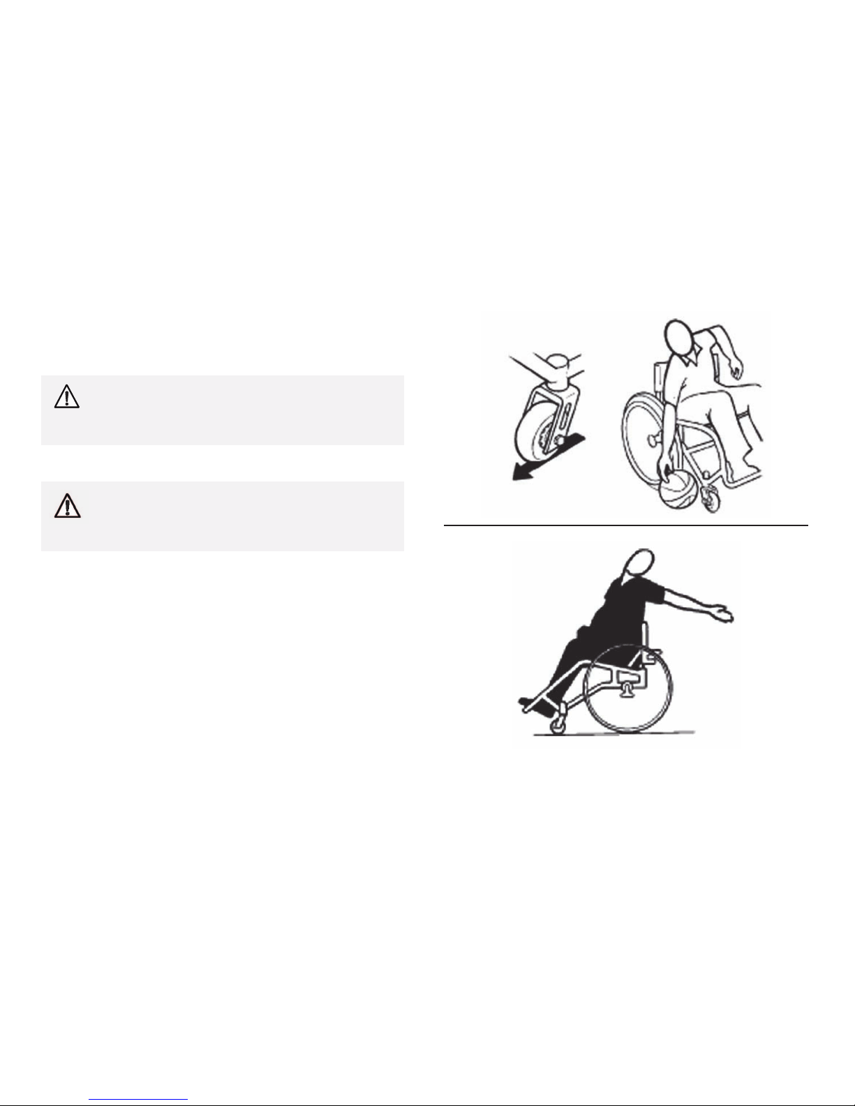
Properpositioningisessentialforyoursafety.Whenreaching,
leaning,bendingforward,itisimportanttousethefrontcastersasa
tooltomaintainstabilityandbalance.
•Lengtheningthewheelbasewillincreasethestabilityand
maintainstandardmaneuverabilityofwheelchair.
•Shorteningthewheelbasewilldecreasethestability,increase
themaneuverabilityanddistributeadditionalweightontothe
rearwheels.
1171801-A
11
TopEnd
®
Terminator™Series
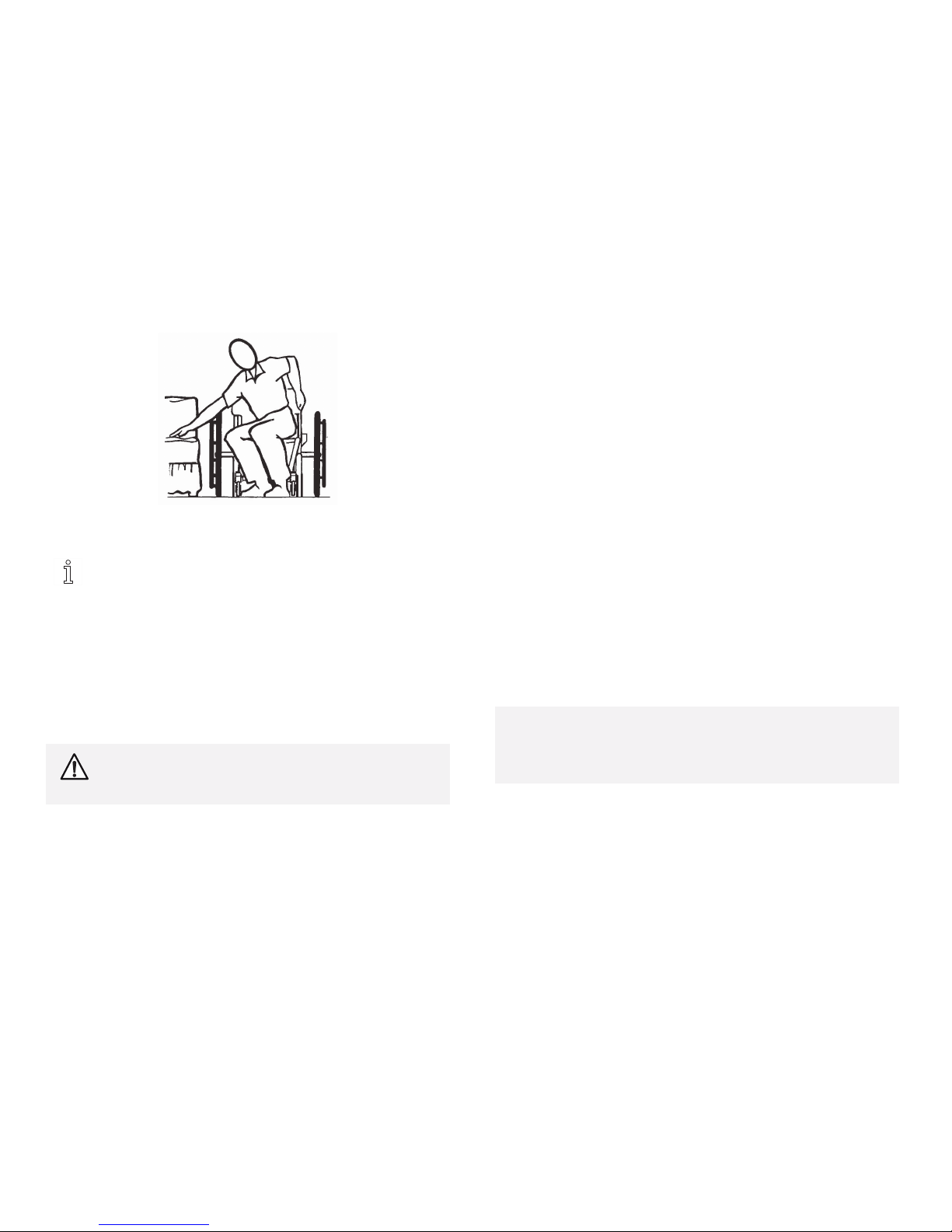
2.8Reaching,LeaningandBending
ForwardorSideways
Positionthefrontcasterssothattheyareextendedasfarforwardas
possibleandengagewheellocks.
WARNING!
–DONOTattempttoreachobjectsifyouhaveto
moveforwardintheseat.orpickthemupfromthe
floorbyreachingdownbetweenyourknees.
Backward
WARNING!
–DONOTleanoverthetopofthebackupholstery.
Thiswillchangeyourcenterofgravityandmaycause
youtotipover.
ForwardorSideways
Backwards
12
1171801-A
Safety
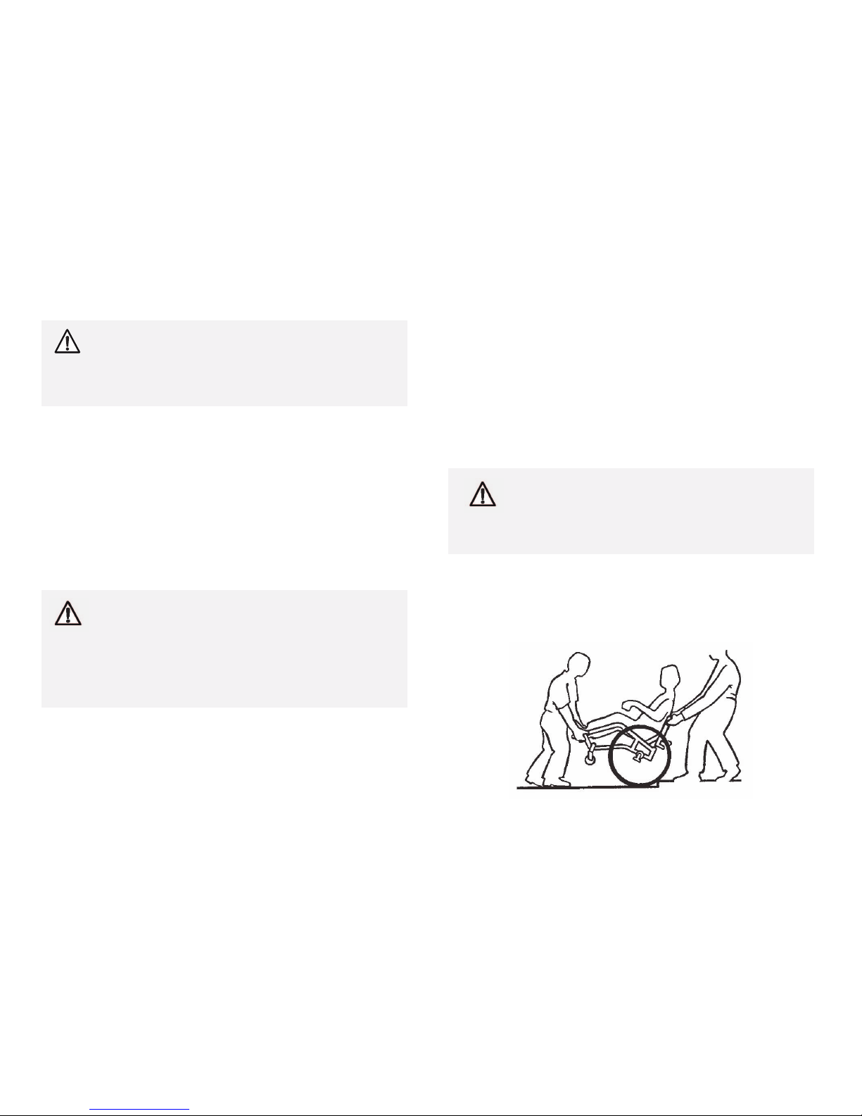
2.9Tipping
WARNING!
–DONOTtipthewheelchairwithoutassistance.
–DONOTletthewheelchairdropthelastfewinches
totheground.Thiscouldresultininjurytothe
occupant.
Whentippingthewheelchair,anassistantshouldgraspthebackof
thewheelchaironanon-removable(non-detachable)part.Inform
thewheelchairoccupantbeforetiltingthewheelchairandremind
him/hertoleanback.Besuretheoccupant’sfeetandhandsareclear
ofallwheelsand/orpinchpoints.Applyacontinuousmotionuntil
thebalancepointisachieved.Atthispoint,theassistantwillfeel
adifferenceintheweightdistribution.Turnthewheelchairinthe
desireddirectionifnecessary.Slowlylowerthewheelchairinone
continuousmovement.
Curbs
WARNING!
–Invacaredoesnotrecommendthatsportwheelchairs
beusedwheretraversingcurbspresentanobstacle.
Possibleinjurytooccupantand/orassistant(s)can
occur.Transfertoaneverydayusewheelchair
isrecommendedifanysuchobstaclesmaybe
encountered.
Aftermasteringthetechniquesoftippingthewheelchair,usethe
followingmethodtotacklecurbs,shortstairs,etc.
Turntheanti-tipperssothewheelsarefacingup.Unlessthefirst
assistanthasexceptionalupperbodystrength,itisrecommended
thattwoassistantsperformthisoperation.Thesecondassistant
shouldbepositionedatthefrontofthewheelchairliftingupward
onanon-removable(non-detachable)partofthewheelchairframe
whenliftingthewheelchairandstabilizingthewheelchairwhenthe
wheelchairisbeingloweredtotheground.
Thefirstassistantshouldstandonthesidewalkandturnthe
wheelchairsothattherearwheelsareagainstthecurb.The
wheelchairshouldbetiltedbacktothebalancepointand,inone
continuousupwardmovement,therearwheelsshouldbepulledup
andoverthecurb.DONOTreturnthefrontcasterstotheground
untilthewheelchairhasbeenpulledbackwardfarenoughforthe
frontcasterstocleartheedgeofthecurb.
WARNING!
–Whenloweringthefrontcastersofthewheelchair,
Donotletthewheelchairdropthelastfewinchesto
theground.Thiscouldresultininjurytotheoccupant
and/ordamagetothewheelchair.
Rollthewheelchairbackwardandslowlylowerthewheelchairinone
continuousmovement.Donotletthewheelchairdropthelastfew
inchestotheground.Thiscouldresultininjurytotheoccupant.
Turntheanti-tipperssothewheelsarefacingdown.
1171801-A13

TopEnd
®
Terminator™Series
2.10Stairways
Followthisprocedureformovingthewheelchairbetweenfloors
whenanelevatorisNOTavailable:
1.Ifequipped,turntheanti-tippersup.Referto4.17
Adjusting/ReplacingFootrest,page46.
2.Afterthewheelchairhasbeentiltedbacktothebalance
point,oneassistant(intherear)backsthewheelchairup
againstthefirststep,whilesecurelygraspinganon-removable
(non-detachable)partofthewheelchairforleverage.
3.Thesecondassistant,withafirmholdonanon-detachablepart
oftheframework,liftsthewheelchairupandoverthestairand
steadiesitasthefirstassistantplacesonefootonthenextstair
andrepeatsprocedure.
4.Thewheelchairshouldnotbelowereduntilthelaststairhas
beennegotiatedandithasbeenrolledawayfromthestairway.
5.Ifequippedturntheanti-tippersdown.Referto4.17
Adjusting/ReplacingFootrest,page46.
WARNING!
–DONOTuseanescalatortomoveawheelchair
betweenfloors.Seriousbodilyinjurymayoccur.
2.11TransferringToandFromOtherSeats
WARNING!
–Beforeattemptingtotransferinoroutofthe
wheelchair,everyprecautionshouldbetakento
reducethegapdistance.Turnbothcastersparallel
totheobjectyouaretransferringonto.Alsobe
certainthewheellocksareengagedtohelpprevent
thewheelsfrommoving.
–Whentransferring,positionyourselfasfarback
aspossibleintheseat.Thiswillpreventdamaged
upholsteryandthepossibilityofthewheelchairtipping
forward.
Thisactivitymaybeperformedindependentlyprovidedyou
haveadequatemobilityandupperbodystrength.
Positionthewheelchairascloseaspossiblealongsidetheseatto
whichyouaretransferring,withthefrontcastersparalleltoit.
Removethearmrest,ifinstalled.Engagewheellocks.Shiftbody
weightintoseatwithtransfer.
Duringindependenttransfer,littleornoseatplatformwillbebeneath
you.Useatransferboardifatallpossible.
14
1171801-A
Safety
2.12SafetyInspectionChecklist
Everysixmonthsorasnecessary,takeyourTopEnd
wheelchairtoaqualifiedtechnicianforathoroughinspection
andservicing.Regularcleaningwillreveallooseorworn
partsandenhancethesmoothoperationofyourwheelchair.
Tooperateproperlyandsafely,yourwheelchairMUSTbe
caredforjustlikeanyothervehicle.Routinemaintenance
willextendthelifeandefficiencyofyourwheelchair.Clean
upholsterywithmildsoapandwaterorspraydisinfectant
usingasponge.DONOTusebleachorwashinawashing
machine.
WARNING!
–Incasesofinactivitylongerthansixmonths,a
comprehensiveinitialinspectionMUSTbeperformed.
Initialadjustmentsshouldbemadetosuityourpersonalbody
structureandpreference.Thereafterfollowthesemaintenance
procedures:
Inspect/AdjustInitially
qEnsurewheelchairrollsstraight(noexcessivedrag/pulltoone
side).
qEnsurewheellocksDonotinterferewithtireswhenrolling.
qEnsurepivotpointsarefreeofwearandlooseness.
qEnsurewheellocksareeasytoengage.
qInspectseatandbackupholsteryforripsorsagging.
qInspectupholsteryfasteningflapstoensuretheysecurelylatch.
qInspectseatpositioningstrapforanysignsofwear.Ensure
bucklelatches.Verifyhardwarethatattachesstraptoframeis
secureandundamaged.Replaceifnecessary.
qEnsurehandgrips(ifequipped)arenotloose.
qEnsurequickreleaseaxlesandcamberinsertsareclean.
qEnsureadjustableaxlepositioncamberbarissecurelytightened.
qEnsurequick/quadreleaseaxleslockproperly.
qEnsurenoexcessivesidemovementorbindingwhenliftedand
spun.
qInspecthandrimsforsignsofroughedgesorpeeling.
qInspectspokesforbentorbrokenspokes.
qEnsureallspokesareuniformlytight.
qCleanupholsteryandarmrests.
CAUTION!
–Aswithanyvehicle,thewheelsandtiresshouldbe
checkedperiodicallyforcracks,flatspotsandwear,
andshouldbereplacedifdamaged.
qInspectwheel/forkassemblyforpropertensionbyspinning
caster;castershouldcometoagradualstop.
qLoosen/tightenlocknutifwheelwobblesnoticeablyorbinds
toastop.
qEnsurewheelbearingsarecleanandfreeofmoisture.
qInspecttiresforflatspotsandwear.
1171801-A15

TopEnd
®
Terminator™Series
qIfpneumatictirescheckforproperinflation.
qEnsurecastersarefreeofdebris.
qCheckthatalllabelsarepresentandlegible.Replaceifnecessary.
Inspect/AdjustWeekly
qEnsurehandgrips(ifequipped)arenotloose.
qEnsurequickreleaseaxlesandcamberinsertsareclean.
qEnsurequick/quadreleaseaxleslockproperly.
qInspecthandrimsforsignsofroughedgesorpeeling.
qInspectspokesforbentorbrokenspokes.
qEnsureallspokesuniformlytight.
CAUTION!
–Aswithanyvehicle,thewheelsandtiresshouldbe
checkedperiodicallyforcracks,flatspotsandwear,
andshouldbereplacedifdamaged.
qInspectwheel/forkassemblyforpropertensionbyspinning
caster;castershouldcometoagradualstop.
qInspecttiresforflatspotsandwear.
qIfpneumatictirescheckforproperinflation.
qEnsurecastersarefreeofdebris.
Inspect/AdjustMonthly
qEnsurewheellocksDonotinterferewithtireswhenrolling.
qEnsurepivotpointsarefreeofwearandlooseness.
qInspectupholsteryfasteningflapstoensuretheysecurelylatch.
qInspectseatpositioningstrapforanysignsofwear.Ensure
bucklelatches.Verifyhardwarethatattachesstraptoframeis
secureandundamaged.Replaceifnecessary.
qEnsureadjustableaxlepositioncamberbarissecurelytightened.
CAUTION!
–Aswithanyvehicle,thewheelsandtiresshouldbe
checkedperiodicallyforcracks,flatspotsandwear,
andshouldbereplacedifdamaged.
qLoosen/tightenlocknutifwheelwobblesnoticeablyorbinds
toastop.
qEnsurewheelbearingsarecleanandfreeofmoisture.
qEnsurecastersarefreeofdebris.
Inspect/AdjustPeriodically
qEnsurewheelchairrollsstraight(noexcessivedrag/pulltoone
side).
qEnsurewheellocksareeasytoengage.
qInspectseatandbackupholsteryforripsorsagging.
qEnsureadjustableaxlepositioncamberbarissecurelytightened.
qEnsurenoexcessivesidemovementorbindingwhenliftedand
spun.
qInspecthandrimsforsignsofroughedgesorpeeling.
qCleanupholsteryandarmrests.
CAUTION!
–Aswithanyvehicle,thewheelsandtiresshouldbe
checkedperiodicallyforcracks,flatspotsandwear,
andshouldbereplacedifdamaged.
qEnsurewheelbearingsarecleanandfreeofmoisture.
qEnsurecastersarefreeofdebris.
qCheckthatalllabelsarepresentandlegible.Replaceifnecessary.
161171801-A
Overview
3Overview
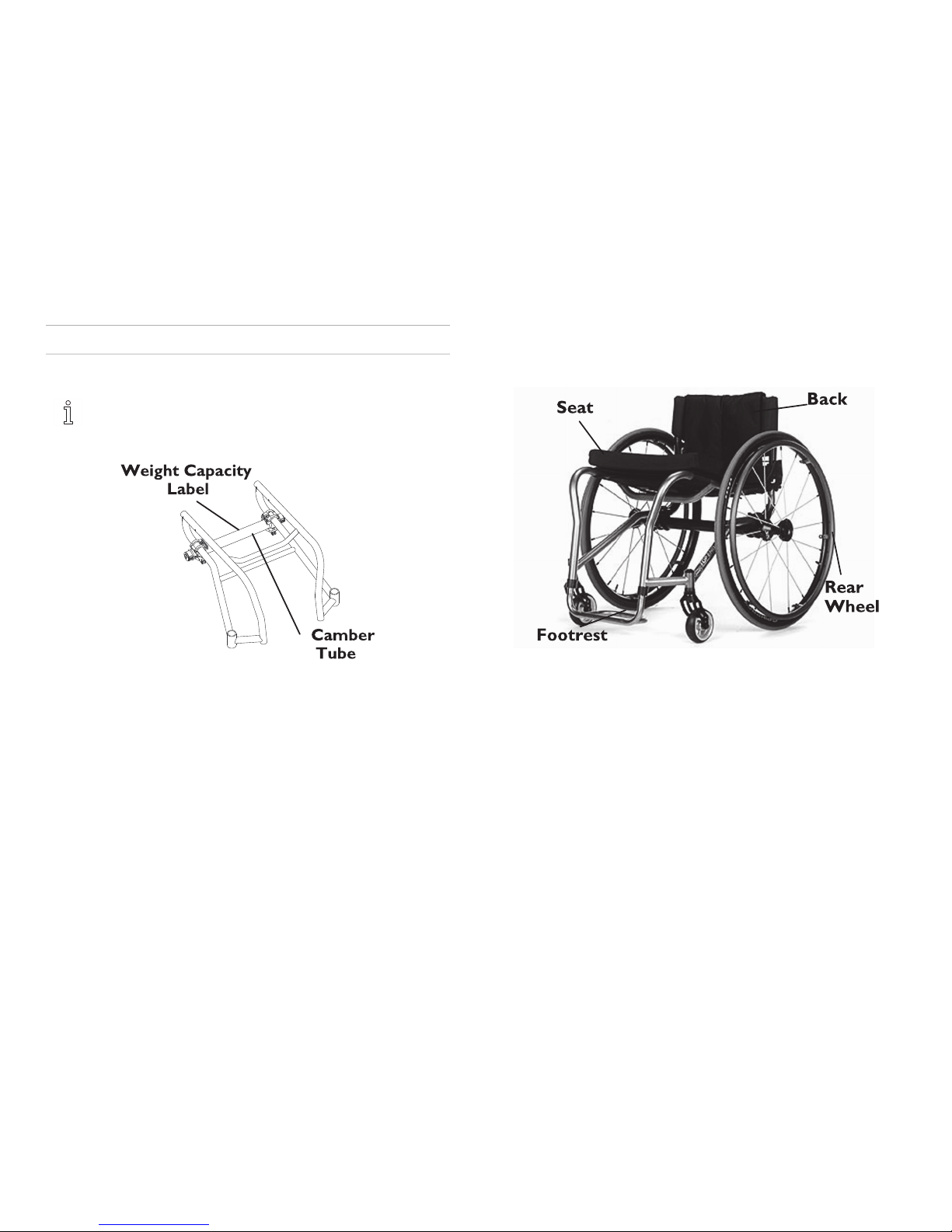
3.1LabelLocationsandComponentIdentification
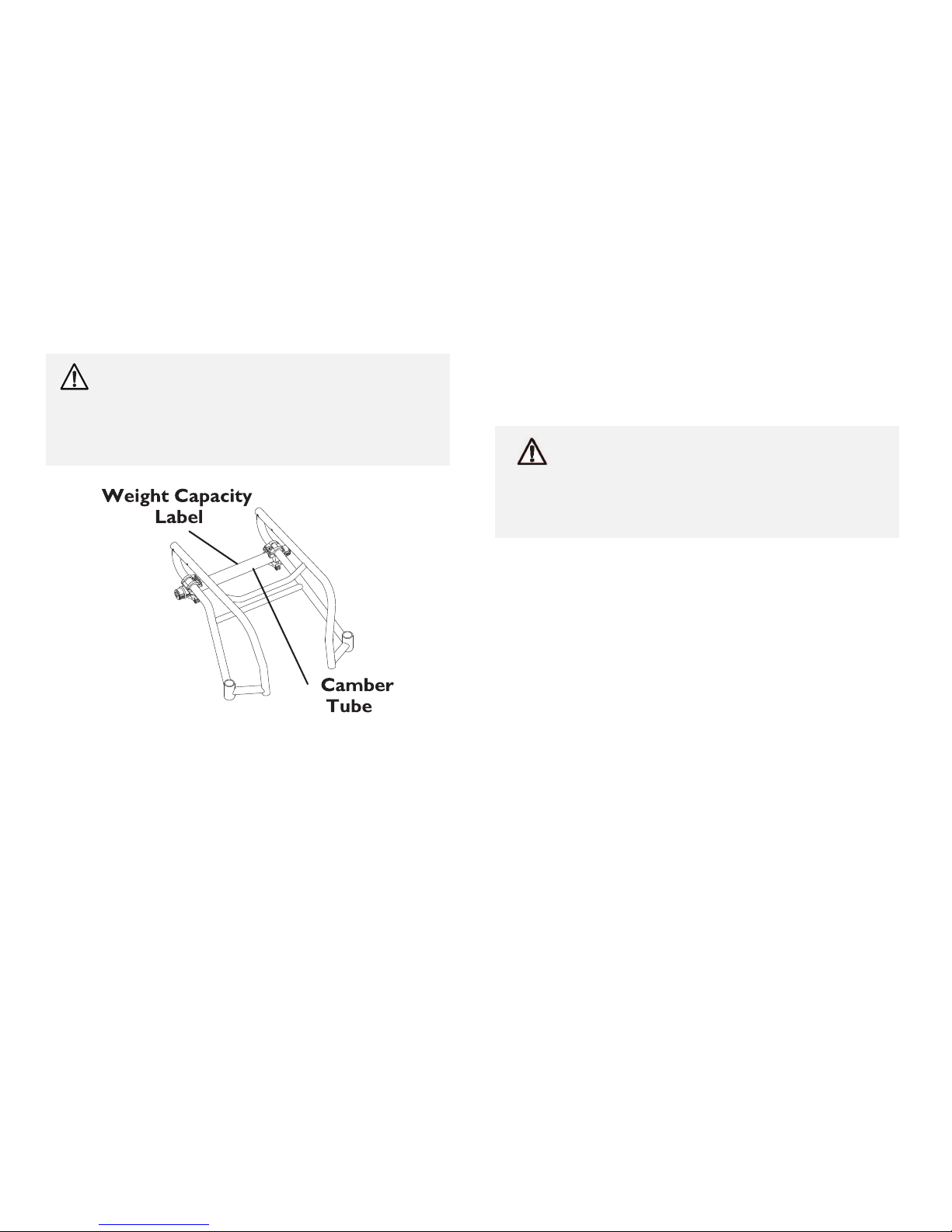
Serialnumberlabelislocatedunderneaththeseat.
Theweightcapacitylabelisonthecambertube.
ComponentIdentification
TerminatorTitanium
1171801-A17

TopEnd
®
Terminator™Series
3.2TypicalProductParameters
TopEndTerminatorTitanium
FRAME:Grade9Titanium.035,heavydutyGrade9Titanium.051wallthickness
SEATWIDTH:
12-18inches(30.48-45.72cm)-OutsidetoOutsideofSEATFRAME
in1-inch(2.54cm)increments
SEATDEPTH:
14to18(35.56-45.72cm)inches
SEAT-TO-FLOOR:
Front-17to21-inch(43.18-53.34cm),Rear-14to21-inch(35.56
-53.34cm)
BACKSTYLE:
Fixed(Standard),FoldDown
BACKHEIGHTFIXED:
8-16inches(20.32-40.64cm)
BACKHEIGHTADJUSTABLE:
9to11,10to14,12to16,14to18and16to20inchesin1-inch
increments.
(20.32-27.94,25.4-35.56,30.48-40.64,35.56-45.72,and40.64-
50.8cmin2.54cmincrements)
BACKANGLEFOLDING:
90°straight,4°backward,4°forwardor8°forward
BACKANGLEFIXED:
0°,3°,6°or9°
REAR-FRONTCASTERDISTANCE:
17to2inches(43.18-53.34cm)(Fromoutsideofbackofframeto
centeroffrontcasterhousing)
FRONTCASTERTOFOOTPLATEDISTANCE:
3to5inches(7.62-12.7cm)
FOOTWIDTH:
9to12inches(22.86-30.48cm)(Averageis10-inches(25.4cm)
betweenfrontoffootrestbars)
FOOTREST:
Tubular:4-inch(10.16cm)HeightAdjustable(Standard)
SIDE-WHEELCLEARANCE:
Adjustable1/2to1-1/2-inches(1.27-3.81cm)
181171801-A

Overview
TopEndTerminatorTitanium
REARAXLE:AdjustableAxlePosition,Quick(Standard)orQuad-Release
REARWHEELCAMBER—CAMBERTUBE2000:
0°,3°,6°,9°
REARWHEELCAMBER—ADJUSTABLECAMBER
SYSTEM:
0°,3°,6°,9°,12°
REARWHEELS
22–INCH(21.22ZOLL)
24–INCH(23.14ZOLL)(STANDARD)
25–INCH(24.1ZOLL)
26–INCH(25.1ZOLL)
SunHighperformance(Standard),SpinergySPOX,SpinergyLX
TIRES*
22–INCH(21.22ZOLL)
24–INCH(23.14ZOLL)(STANDARD)
25–INCH(24.1ZOLL)
26–INCH(25.1ZOLL)
1inch(2.54cm)PrimoHighpressureclincher(standard),1–inch
(2.54cm)Kenda,1inch(2.54cm)Schwallbeflatresistant,13/8–inch
(3.49cm)w/flatfreeinserts,1–inch(2.54cm)solid,2–inch(5.08cm)
knobby
HANDRIMS:
AluminumWeldedTab(Standard)PlasticCoated,NaturalFit®,
Titanium
WHEELLOCKS:
HighMount(Standard),Undermount(Optional)
FRONTFORKS:
Non-Suspension(Standard),Suspension
CASTERSIZE:
3,4,5and6-inch(7.62,10.16,12.7and15.24cm)
BACKUPHOLSTERY:
U240Black-AdjustableTensionorBreathableMesh-Adjustabletension
WEIGHT:
17lbs(7.71kg)
1171801-A19

TopEnd
®
Terminator™Series
SHIPPINGWEIGHT:
30lbs(13.6kg)
WEIGHTCAPACITY:
250lbs(113.4kg)/400lbs(181.44kg)withHeavyDutyOption
TopEndTerminatorEveryday
FRAME:6061T6Aluminum.083,HeavyDutyOption4031Chrome-molysteel.
SEATWIDTH:
12-18inches(30.48-45.72cm)-OutsidetoOutsideofSEATFRAME
in1-inch(2.54cm)increments
SEATDEPTH:
14to18inches(35.56-45.72cm)
SEAT-TO-FLOOR:
Front-17to21-inch(43.18-53.34cm),Rear-14to21-inch(35.56
-53.34cm)
BACKSTYLE:
Fixed(Standard),FoldDown
BACKHEIGHTFIXED:
8-16inches(20.32-40.64cm)
BACKHEIGHTADJUSTABLE:
9to11,10to14,12to16,14to18and16to20inchesin1-inch
increments.
(20.32-27.94,25.4-35.56,30.48-40.64,35.56-45.72,and40.64-
50.8cmin2.54cmincrements)
BACKANGLEFOLDING:
90°straight,4°backward,4°forwardor8°forward
BACKANGLEFIXED:
0°,3°,6°or9°
REAR-FRONTCASTERDISTANCE:
17to2inches(43.18-53.34cm)(Fromoutsideofbackofframeto
centeroffrontcasterhousing)
FRONTCASTERTOFOOTPLATEDISTANCE:
3to5inches(7.62-12.7cm)
FOOTWIDTH:
9to12inches(22.86-30.48cm)(Averageis10-inches(25.4cm)
betweenfrontoffootrestbars)
FOOTREST:
Tubular:4-inch(10.16cm)HeightAdjustable(Standard)
201171801-A

Overview
TopEndTerminatorEveryday
SIDE-WHEELCLEARANCE:
Adjustable1/2to1-1/2-inches(1.27-3.81cm)
REARAXLE:AdjustableAxlePosition,Quick(Standard)orQuad-Release
REARWHEELCAMBER—CAMBERTUBE:
0°,3°,6°,9°
REARWHEELCAMBER—ADJUSTABLECAMBER
SYSTEM:
0°,3°,6°,9°,12°
REARWHEELS
22–INCH(21.22ZOLL)
24–INCH(23.14ZOLL)(STANDARD)
25–INCH(24.1ZOLL)
26–INCH(25.1ZOLL)
SunHighperformance(Standard),SpinergySPOX,SpinergyLX
TIRES*
22–INCH(21.22ZOLL)
24–INCH(23.14ZOLL)(STANDARD)
25–INCH(24.1ZOLL)
26–INCH(25.1ZOLL)
1inchPrimoHighpressureclincher(standard),1–inch(2.54cm)Kenda,
1inch(2.54cm)Schwallbeflatresistant,13/8–inch(3.49cm)w/flatfree
inserts,1–inch(2.54cm)solid,2–inch(5.08cm)knobby
HANDRIMS:
AluminumWeldedTab(Standard)PlasticCoated,NaturalFit®,
Titanium
WHEELLOCKS:
HighMount(Standard),Undermount(Optional)
FRONTFORKS:
Non-Suspension(Standard),Suspension
CASTERSIZE:
3,4,5and6-inch(7.62,10.16,12.7and15.24cm)
BACKUPHOLSTERY:
U240Black-AdjustableTensionorBreathableMesh-Adjustabletension
WEIGHT:
17lbs(7.71kg)
1171801-A
21

TopEnd
®
Terminator™Series
SHIPPINGWEIGHT:
30lbs(13.6kg)
WEIGHTCAPACITY:
250lbs(113.4kg)/350lbs(158.75kg)withHeavyDutyOption
–15x15-inch(38.1cm)seat,rearwheelsandminimal
optionsareincludedintheweight.
–*Referto3.3TirePressureConversion,page23.
–Allspecificationsareapproximate.
22
1171801-A

Overview
3.3TirePressureConversion
Ifequippedwithhighpressuretires,aPrestavalveadaptor
willbeneededtoinflatethetirestotherecommended
pressuresbelow.
PSIratingisprintedonthesideofthetire.Conversion
formula:1psi=6.895kPa(approx.7kPa).
PSIKILSOPASCALSPSIKILOPASCALS
5034590621
55
37995655
60414100690
65448105724
70483110758
75
517115793
80552120827
85586
1171801-A23

TopEnd
®
Terminator™Series
4Operation
4.1Unfolding/FoldingtheBack
WARNING!
–Afteranyadjustments,repairorserviceandbefore
use,makesureallattachinghardwareistightened
securely.Otherwiseinjuryordamagemayoccur.
–ALWAYSperformtheseproceduresinthepresence
ofanassistant.Thepositionofthefootrest,camber
tube,backangle,thetautnessofthebackupholstery
aswellastheuser’sconditionaredirectlyrelatedto
thewheelchairsstability.Anychangetooneorany
combinationofthefivemaycausethewheelchairto
decreaseinstability.Useextremecautionwhenusing
anewseatingposition.Theadditionofanti-tippers
mayberequired.
–Thepositionofthefootrest,seatangle,backangle,
seatingsystem/upholstery,castersizeandposition,
rearwheelsizeandposition,useofanti-tippers,
aswellastheuserconditiondirectlyrelatetothe
stabilityofthewheelchair.Anychangetooneorany
combinationofthetenmaycausethewheelchairto
decreaseinstability.EXTREMEcaremustbetaken
whenchangingthestabilityofthewheelchair.
WARNING!
–BackMUSTbelockedsecurelyinplacebeforeusing
thewheelchair.
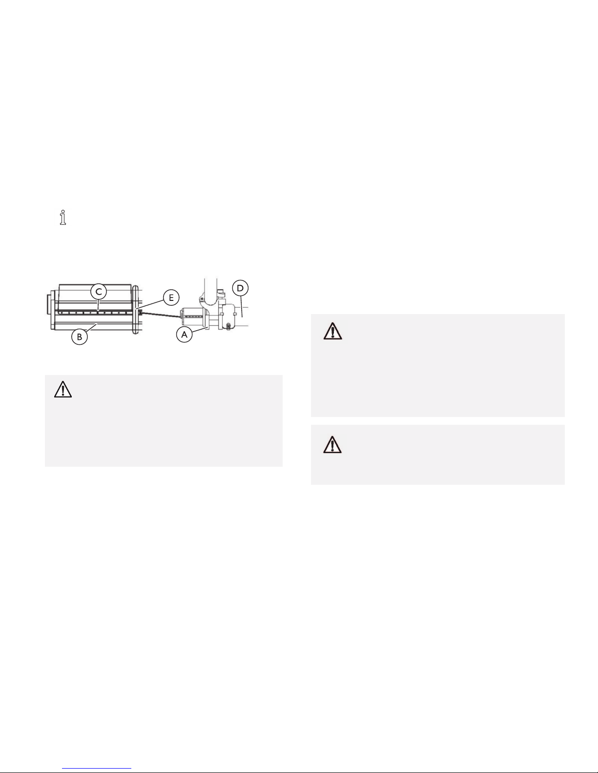
Backupholsteryremovedforclarity.
1.Tounfoldtheback,liftuponthebackpostsAandpullback
towardstherearofthewheelchairuntilitlocksintoplace.
2.Tofoldtheback,pulluponthebackreleasecordandpushthe
backpostsAforwardtowardthefrontofthewheelchair.
24
1171801-A

Operation
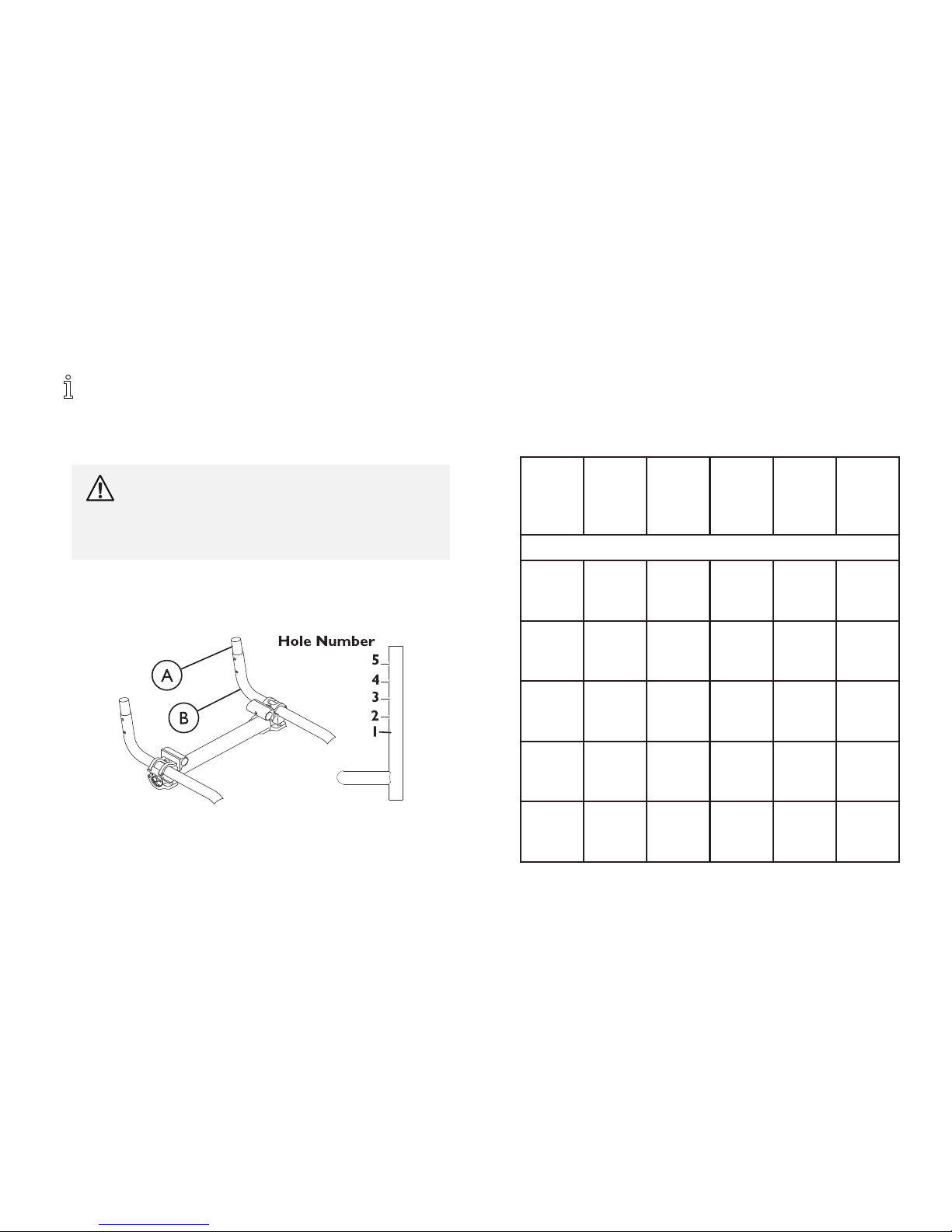
4.2BackAngleAdjustment
WARNING!
–Iftheadjustmentsquareisinstalledintothebackangle
platesothatanumberdoesnotappearnexttothe
indent,DONOTusethisposition,otherwiseinjury
willoccur.Thispositionoftheadjustmentsquare
doesnotallowthelockingpinstolockintoposition
whenthebackisraised.
–Afterunfoldingtheback,ensurethattheplunger
pinsarefullyengagedinthemountingholesofthe
adjustmentsquareinthebackangleplates.Otherwise,
seriousinjurycouldresult.
Thenumbersonthebackangleplateareintendedtodefine
theresultingbackangleofachairthathas2inch(5.08cm)
seatdrop[at17inch(43.18cm)depth]andthatismeasured
relativetotrueverticalwiththechairsittingonalevel
surface.Theplus(+)signincreasesthebackangleand
theminus(-)signdecreasesthebackangle.Theresulting
backanglewillvarysomewhatdependingonyourchair
configuration.Refertofigureonpage25–26toseethese
settingsconvertedintobackanglerelativetotheseat.
Performthisprocedureonbothsidesofthewheelchairat
thesametime.
Notetheindentontheadjustmentsquare.Whenthe
adjustmentsquareispositionedinthebackangleplate,
thenumberthatislocateddirectlynexttotheindentwill
bebackanglerelativetotruevertical.Onesideofthe
adjustmentsquareprovidesbackanglesof+8°,0°and-4°.
Fliptheadjustmentsquareovertoobtainbackanglesof
-8°,+4°and0°.
Whenadjustedproperly,thebackshouldhaveasmall
amountofmovementwhenlockedintheopenposition.
Plungerpinsshouldsnapinandreleaseeasilywithout
resistance.
DETAIL“A”
1.Folddowntheback.Referto4.1Unfolding/FoldingtheBack,
page24.
2.LoosenthejamnutAontheplacementscrewBlocatedatthe
bottomofthebackcaneC(Detail“A”).
1171801-A25

TopEnd
®
Terminator™Series
DETAIL“B”
3.TightentheplacementscrewBsothatthescrewandjamnutA
aresnugagainstthebottomofthebackcaneC(Detail“B”).
DETAIL“C”
4.RemovethemountingscrewAthatsecurestheadjustment
squareD(inDetail“A”)andB(inDetail“C”)tothebackangle
plateC(Details“A”and“C”).
5.RemovetheadjustmentsquareBfromthebackangleplateC
(Detail“C”).
6.PositiontheadjustmentsquareBinthebackplateCwiththe
indentlocatedunderneaththedesiredbackangle.
7.SecuretheadjustmentsquareBtothebackangleplateCwith
themountingscrewA.Tightensecurely.
8.RepeatSTEPS2-6forremainingbackcaneC(Detail“A”).
9.Unfoldthebackuntiltheplungerpinslockintothemounting
holesintheadjustmentsquareB.
DETAIL“D”
10.UnthreadthemountingscrewAuntilheadofscrewrestson
seatrailB(Detail“D”).
11.CompletelytightenjamnutCupagainstbottomofbackcaneD
(Detail“D”).
261171801-A

Operation
ADJUSTMENTSQUAREPOSITION
DESIREDSEATANGLE
NUMERICALGRAPHICAL
–8°
-4°
0°
OPTION1
OPTION2
1171801-A27

TopEnd
®
Terminator™Series
ADJUSTMENTSQUAREPOSITION
DESIREDSEATANGLE
NUMERICALGRAPHICAL
+4°
+8°
281171801-A

Operation
4.3AdjustableTensionBackUpholstery
WARNING!
–Thepositionofthefootrest,seatangle,backangle,
seatingsystem/upholstery,castersizeandposition,
rearwheelsizeandposition,useofanti-tippers,
aswellastheuserconditiondirectlyrelatetothe
stabilityofthewheelchair.Anychangetooneorany
combinationofthetenmaycausethewheelchairto
decreaseinstability.EXTREMEcareMUSTbetaken
whenchangingthestabilityofthewheelchair.Referto
thechartin2.2StabilityWarning,page7
.
TheAdjustableTensionStraps
Thestrapscanbeadjustedatvariouslevelsoftensionto
accommodateindividualend-users.Thebottomtwostrapscanbe
adjustedtightlytosupportand/orassisttheextensormuscles.
TheBackUpholsteryCover
Thebackupholsterycoverisdesignedforthreereasons:
•Thefirstisasamodestycover.
•Thesecondistokeepthecushionfromslidingoutoftheback
ofthewheelchair.
•Thethirdisasacralsupportdependinguponhowfarortight
theflapispulledundertheseatcushion.
ReplacingAdjustableTensionBackUpholstery
1171801-A29

TopEnd
®
Terminator™Series
1.RemovethebackheightadjustmentscrewsAthatsecurethe
backpostsBtothebackuprightsC.
2.SlidethebackpostsBoutofthebackuprightsC.
3.RemovethetwoscrewsandwashersDthatsecuretheexisting
backupholsterytothebackpostsB.
4.SlidetheexistingbackupholsterydownandoffthebackpostsB.
5.Standbehindthewheelchairandperformthefollowing:
a.Slideanchorloopsectionofadjustabletensionback
upholsteryEupontotheleftbackpostBwiththeupper
grommetholeFfacingtherearofthewheelchair.
b.Slideadjusterstrapsectionofadjustabletensionback
upholsteryGupontotherightbackpostBwiththeupper
grommetholeFfacingtherearofthewheelchair.
6.AlignthemountingholeineachbackpostBwiththedesired
mountingholeHineachbackuprightC.
7.InstallthetwobackheightadjustmentscrewsAthroughthe
backuprightmountingholesHdeterminedinstep6andthe
backpostmountingholesiI.
8.SlipadjusterstrapsJthroughcorrespondinganchorloopsK
andadjustthebackupholsteryL.Securewiththefastening
strapsM.
Bothbackpostsshouldbeadjustedtothesameheight.
WARNING!
–Aftertheadjustabletensionbackupholstery
hasbeenpositionedtotheend-usersindividual
needs,thefasteningstrapsMUSTbesecurely
fastenedBEFOREapplyingthebackupholstery
cover.Theadjustablebackshouldbechecked
wheneverenteringthewheelchairtoensurethat
thefasteningstrapsaresecurelyfastened.
9.Securethebackupholsterycover(fasteningstrap)Mtotheback
oftheadjustablebackupholstery(fasteningstrap).
10.FlipthebackupholsterycoverLovertheadjustableback
upholsteryandsecurethefasteningstrapsMtothefrontof
theadjustablebackupholstery.
11.LaythefrontportionofthebackupholsterycoverLonthe
seatpan.
12.AdjusttheslackinthebackupholsterycoverLandthensecure
totheseatpanfasteningstraps.
301171801-A
Operation
4.4BackHeightAdjustment(AdjustableBack
Only)
Observethetautnessofthebackupholsteryfor
reinstallation.
1.Unlatchthetwofasteningflapsthatsecurethetopoftheback
upholsterytothebackpostsandremovefromthebackposts.
WARNING!
–PushpinMUSTbeprotrudingthroughholein
backpostB.
–EnsurethatbothbackpostinsertsAareatthe
sameheightBEFOREreassemblingthewheelchair.
2.PressthepushpinonthebackpostinserttubeAinandadjust
thebackheighttooneoffourheightsdependingonoriginalback
height:
*Holesnumberedfrombottomtotopforreference
only.(Therearenonumbersonthebackposts.)
Thereisa1-inch(2.54cm)adjustmentpinonthebackpost
inserttubeA.Toraisebacktomaximumheight,firstmake
adjustmenttothebackpostinsertsA.
ThefasteningflapwithlogoisfortheleftbackpostB.
Rightandleftisdeterminedbysittinginthewheelchair.
3.ReinstallthefasteningflapsontothebackpostsB.
4.Adjustthenewbackupholsterytothedesiredtautness.
Original
Back
Height
9–11
(22.86in
–27.9
4cm)
10–14
(25.40in
–35.5
6cm)
12–16
(30.48in
–40.6
4cm)
14–18
(35.56in
–45.7
2cm)
16–20
(40.64in
–
50.8cm)
Hole*Number
1
9in
(22.86
cm)
10in
(25.40
cm)
12in
(30.48
cm)
14in
(35.56
cm)
16in
(40.64
cm)
2
10in
(25.40
cm)
11in
(27.94
cm)
13in
(33.02
cm)
15in
(38.10
cm)
17in
(43.18
cm)
3
11in
(27.94
cm)
12in
(30.48
cm)
14in
(35.56
cm)
16in
(40.64
cm)
18in
(45.72
cm)
4
N/A
13in
(33.02
cm)
15in
(38.10
cm)
17in
(43.18
cm)
19in
(48.25
cm)
5
N/A
14in
(35.56
cm)
16in
(40.64
cm)
18in
(45.72
cm)
20in
(50.8
cm)
1171801-A31

TopEnd
®
Terminator™Series
4.5AdjustingtheT-Arms
AdjustingT-ArmHeight
1.UnlocktheT-armEbyflippingtheT-armreleaselevertowards
theinsideofthewheelchair.
Ifnecessary,pulloutontheT-armreleaseleverand
rotate180°soitcanbeflippedtowardstheoutsideof
thewheelchair.
2.SlidetheT-armtooneof:
•LowHeightT-Arms-Ninepositions.
•HighHeightT-Arms-Sevenpositions.
IftheinsideT-armpostAdoesnotslideupand
downintheoutsideT-armpostCasdesired,
performoneofthefollowing:
3.Tighten-TighteningthesetscrewsDontheoutsideT-arm
postCwillmakeitmoredifficulttomovetheinsideT-armA
postupanddown.
4.Loosen-LooseningthesetscrewsDontheoutsideT-armpost
CwillmakeiteasiertomovetheinsideT-armApostupand
down.
5.LocktheT-armbyflippingtheT-armreleaseleverBtowards
thefrontofthewheelchair.
AdjustingT-ArmWidth
1.RemovethetwomountingscrewsAthatsecurethearmpad
BtothearmtubeC.
2.TurnthearmpadBaroundandrepositionthearmpadBon
thearmtubeC.
3.Re-securethearmpadBtothearmtubeCwiththetwo
mountingscrewsA.Tightensecurely.
4.Repeatfortheoppositeside,ifnecessary.
321171801-A

Operation
AdjustingT-ArmDepth
1.RemovethetwomountingscrewsCthatsecurethearmpad
AtothearmtubeD.
2.RemovethetwosocketscrewsBthatsecurethearmtube
DtotheT-armpostE.
3.RepositionthearmtubeDontheT-armpostE:
•DeskLengthArms-tooneofthreepositionsdependingon
thedesiredarmpadAdepth.
•FullLengthArms-tooneoffivepositionsdependingon
thedesiredarmpadAdepth.
Additionalpositionsareobtainablebyturningthe
armtube180°.
4.Re-securethearmtubeDtotheT-armpostEwiththetwo
socketscrewsB.Torqueto60-70in./lbs(152.4–177.8cm/kg).
5.ReattachthearmpadAtothearmtubeDwiththetwo
mountingscrewsC.Tightensecurely.
6.Repeatfortheoppositeside,ifnecessary.
4.6AdjustingT-ArmSockets
PerformthisprocedureiftheT-armAistoolooseinthe
socketordoesnoteasilyslideupanddowninthesocket.
1.Removetherearwheelsfromthewheelchair,ifnecessary.Refer
to5.7Removing/InstallingRearWheels,page52.
2.Loosen,butdonotremovethefoursocketscrewsandwashers
EthatsecureouterT-armbracketDtotheinnerT-arm
bracketC.
TheT-armsocketwilldisassembleifthefoursocket
screwsandwashersEareremoved.
1171801-A33

TopEnd
®
Terminator™Series
3.SlidetheT-armAintotheT-armsocketuntilthelockinglever
FisintheslotBintheT-armsocketandanaudible"click"is
heard.
4.SqueezetheouterT-armbracketDandtheinnerT-armbracket
CtogetheruntilthesocketisflushwiththeT-armA.
5.WhileholdingtheouterandtheinnerT-armbracketstogether,
tightenthefoursocketscrewsandwashersE.Tightensecurely.
6.PressinonthelockingleverFandlifttheT-armstraightup
andoutoftheT-armsocket.
7.RepeatSTEPS3-6,ifnecessaryuntiltheT-armAslidesinthe
T-armsocketasdesired.
8.Ifnecessary,installrearwheels.Referto5.7Removing/Installing
RearWheels,page52.
4.7AdjustingQuick-ReleaseAxles
1.Removerearwheelandquick-releaseaxleBfromthe
wheelchair.Referto5.7Removing/InstallingRearWheels,page
52andto5.10ReplacingQuad-ReleaseAxles,page54.
2.DepressdetentpinAinthequick-releaseaxleBandslideaxle
throughthewheelhubC.
3.ReleasedetentpinAensuringthatthelockingpinsDarefully
released.
4.IncreaseordecreaseendplaybyadjustingthelocknutEonthe
endofthequick-releaseaxleB.
5.Installrearwheelontothewheelchair.Referto5.7
Removing/InstallingRearWheels,page52.
EndofQuickReleaseaxleisshownforreferenceonly.Itis
notvisiblewheninsertedintocamberbar.
341171801-A

Operation
4.8AdjustingQuad-ReleaseHandles
1.Removerearwheelandthequad-releaseaxleAfromthe
wheelchair.Referto.
2.LoosenthelockingscrewB.
3.Makeoneorbothofthefollowingadjustments:
•IfthequadreleasehandleAisnotreleasingthelockingpins
completely,rotatethequad-releasehandleAapproximately
one-quarterturnclockwise.
•Ifthequad-releasehandleAhitsthespokesoftherear
wheelwhenassembled,rotatethequad-releasehandleA
approximatelyone-quarterturncounterclockwise.
4.TightenthelockingscrewB.
5.Installtherearwheelandquad-releaseaxleAontothe
wheelchair.Referto.
6.Flipthehandleofthequad-releaseaxleAdowntoreleasethe
detentpinensuringthatthelockingpinsarefullyreleased.
7.Repeatthisprocedureuntilthequad-releaseaxlelockscorrectly.
4.9RemovingPlayfromRearWheels
Withtherearwheelandquad-releaseaxleAstillmountedonthe
wheelchair,tightenthelengthadjustingscrewCuntilthereisnoin
andoutmovementofthequad-releaseaxleAandrearwheel.
Refertodiagramin4.8AdjustingQuad-ReleaseHandles,
page35
4.10Opening/ClosingCamberClamps
WARNING!
STANDARDANDSUSPENSIONCAMBER
CLAMPS
–Makesurethehexscrewsaresecurelytightened
beforeusingwheelchair,otherwisepersonalinjuryor
damagetothewheelchairmayoccur.
QUICKRELEASELEVERS
–Makesurethequickreleaseleversareintheclosed
positionbeforeusingthewheelchair,otherwise
personalinjuryordamagetothewheelchairmay
occur.
CAUTION!
ADJUSTABLECAMBERSYSTEMONLY
–DONOTclosethequick-releaseleversortightenthe
socketscrewsorhexscrewswithoutcamberinserts
intheaxletube.Damagetotheaxletubewilloccur.
1.Performoneofthefollowingtoopenacamberclamp:
•Quick-ReleaseLevers-PullthequickreleaseleverAto
theopenpositionD.
•StandardCamberClamps-Loosen,butdonotremovethe
socketscrewBonthecamberclampA.
1171801-A35

TopEnd
®
Terminator™Series
•SuspensionCamberClamps-Loosen,butdonotremove
thehexscrewDonthebottomrearofthecamberclamp
A.
2.Performoneofthefollowingtocloseacamberclamp:
•QuickReleaseLevers-SecurethequickreleaseleverAto
thecamberclampBbythreadingitcompletelyintothe
camberclampB.PushthequickreleaseleverAonthe
camberclampsBtotheclosedpositionC.
SideViewofQuickReleaseLever
•StandardCamberClamps-Securelytightenthesocket
screwBtosecuretheaxletube.
SideViewofStandardCamberClamp
•SuspensionCamberClamp-Securelytightenthehexscrew
DonthebottomrearofthecamberclampAtosecure
theaxletubeC.
RearViewofSuspensionCamberClamp
361171801-A

Operation
4.11AdjustingRearWheelCamber
CamberTubewithSingleCamber
Theaxletubemustbereplacedtochangethecamber.Referto5.11
ReplacingAxleTube,page55.
AdjustableCamberSystem
–Performthisproceduretoonesideofthewheelchair
atatimeforeaseofadjustment.
–Beforeusingthewheelchair,makesurebothcamber
insertsaresettothesameindexingmark.Thiswill
makesurethedistancebetweentherearwheeland
thewheelchairisthesameonbothsides.
1.OpenthecamberclampA.
2.PullonerearwheelwithcamberinsertBoutofaxletubeC.
3.RemovetherearwheelfromthecamberinsertB.
4.RotatethecamberinsertB180°.
5.ReinstalltherearwheelintothecamberinsertB.
WARNING!
–NEVERpositionthecamberinsertsintheaxle
tubewithmorethan3-inches(7.62cm)(12
indexingmarksshowing)ofthecamberinsert
outsideoftheaxletube.
–Thecamberinsertswillnotbesecurelytightened
intheaxletube.Possibleinjurytotheuserand/or
damagetothewheelchairmayoccur.
6.PositionthecamberinsertBtothedesiredposition.Makesure
thereisnomorethan3inches(7.62cm)(12indexingmarksE)
ofthecamberinsertsBoutsideoftheaxletubeC.
7.SlidetheindexingringDonthecamberinsertBuntilitisflush
withthecamberclampA.
8.ClosethecamberclampA.Referto4.10Opening/Closing
CamberClamps,page35.
9.RepeatSTEPS1-8foroppositesideofwheelchair.
10.Installrearwheeltothewheelchair.Referto5.7
Removing/InstallingRearWheels,page52.
11.Adjusttoein/toeoutofwheelchair.Referto4.13AdjustingToe
In/ToeOut,page39.
4.12DeterminingToeIn/ToeOut
1.Inflateallpneumatictyrestorecommendedtyrepressures(listed
onthesidewallofthetire).
2.MeasurethedistancebetweenthecenterlinesAattherearand
frontoftherearwheelsatapproximately12inches(30.48cm)
fromtheground/floor.
–Foroptimumaccuracy,performSTEP2withthe
wheelchairoccupied.
1171801-A37

TopEnd
®
Terminator™Series
3.Determinedifferencebetweentwomeasurements.Ifdifference
betweenthetwomeasurementsisgreaterthan1/2-inch(1.27
cm)(0+1/4-inch(0.63cm)formaximumrollability),oneoftwo
conditionsexists:
•Ifthebackcenterlinemeasurementoftherearwheelsis
SMALLERBthanthefrontcenterlinemeasurementofthe
rearwheels,aTOE-OUTconditionCexists.
•Ifthebackcenterlinemeasurementoftherearwheelsis
LARGERDthanthefrontcenterlinemeasurementofthe
rearwheels,aTOE-INconditionEexists.
4.Ifthedifferencebetweenthemeasurementsisgreaterthan
1/2-inch(1.27cm),correctthetoe-in/toe-outcondition.
TopViewof
Wheelchair
TopViewof
Wheelchair
381171801-A

Operation
4.13AdjustingToeIn/ToeOut
CamberTubewithSingleCamber
1.Openthecamberclamps.
2.Slowlyrotatethecambertubeineitherdirectionuntiltherear
wheelsareapproximatelyinastraightline.
3.Closethecamberclamps.
4.Measurethedistancebetweenthecenterlinesattherearand
frontoftherearwheelsatapproximately12inches(30.48cm)
fromtheground/floor.
5.RepeatSTEPS1-4untilthetoein/toeoutmeasurementisless
than1/2-inch(1.27cm)(0+
1/4-inch(0.63cm)formaximum
rollability).
AdjustableCamberSystem
CourseAdjustment
–Thisprocedureisrequiredanytimetheaxletubeis
movedfromthefactorysetpositionorisreplaced.
–Makethefollowingadjustmentforonecamberata
time.
–Rearwheelsareremovedfromthedrawingsfor
clarity.Thereisnoneedtoremoverearwheelsfrom
thewheelchairduringadjustment.
–Theillustrationshowstwoexamplesofhowthe
adjustmentringscanbepositioned.
1.OpenthecamberclampsA.
2.LoosenthePhillips™screwsthatsecuretheadjustmentringsB
totheaxletube.
3.SlowlyrotatetheaxletubeAuntiltherearwheelsare
approximatelyinastraightline.
4.ClosethecamberclampA.
5.Measurethedistancebetweenthecenterlinesattherearand
frontoftherearwheelsatapproximately12inches(30.48cm)
fromtheground/floor.
6.RepeatSTEPS1-4untilthetoein/toeoutmeasurementisless
than1/2-inch(1.27cm)(0+
1/4-inch(0.63cm)formaximum
rollability).
7.RotateeithertherightorleftadjustmentringBuntilthestopC
ontheringisatthetopoftheslotinthecamberclampasshown
andsecurelytightenthePhillips™screwonthepositioned
adjustmentringB.
–DONOTtightenthePhillips™screwontheother
adjustmentringBatthistime.
–RepeatSTEPS1-7ofthisprocedurefortheother
adjustmentringBafterrepositioningthecamber
insert.
1171801-A39

TopEnd
®
Terminator™Series
–WhenpositioningtheotheradjustmentringB,rotate
theringuntilthestopCisatthebottomoftheslot
inthecamberclampA.TherightandleftstopsC
MUSTbepositionedoppositetoeachotherorFine
Adjustmentonpagewillnotworkcorrectly.
–WhentheleftadjustmentringBisadjustedtoa
camber,therightadjustmentringBwillnottouchthe
camberclampAandwhentherightadjustmentring
Bisadjustedtotheothercambertheleftadjustment
ringBwillnottouchthecamberclampA.
Stop-Nottouchingcamber
clamp
Stop-Inpositionforonecamber,
touchingcamberclamp.
Stop-Inpositionforonecamber,
touchingcamberclamp.
Stop-Nottouchingcamber
clamp.
FineAdjustment
1.Openthecamberclamp.
2.SlowlyrotatetheaxletubeAuntilthestopontheopposite
adjustmentringispositionedattheoppositeendofthecamber
clamp.
3.Closethecamberclamp.
401171801-A

Operation
4.14AdjustingWheelbaseLength(Centerof
Gravity)
WARNING!
–ALWAYSperformthisprocedureinthepresenceof
anassistant.Thepositionofthefootrest,camber
tube,backangle,thetautnessofthebackupholstery
aswellastheuser'sconditionaredirectlyrelatedto
thewheelchairsstability.Anychangetooneorany
combinationofthefivemaycausethewheelchairto
decreaseinstability.UseEXTREMEcautionwhen
usinganewseatingposition.Theanti-tippersare
required.
–ThecamberbarisalwaysmountedtotheBOTTOM
ofthewheelchairframe.
1.Performoneofthefollowing:
•Non-Suspension-Loosen,butdonotremovethehex
screwAthatsecureseachofthetopclampsBtothe
wheelchairframeC.
•Suspension-Loosen,butdonotremovethetwohex
screwsAthatsecureeachofthetopclampsBtothe
wheelchairframeC.
2.Positionthecamberclampsonthewheelchairframeatthe
desiredposition.
•LengtheningtheWheelbaseD-Willincreasethestability
andmaintainstandardmaneuverabilityofthewheelchair.
•ShorteningtheWheelbaseE-Willdecreasethestability,
increasethemaneuverabilityanddistributeadditionalweight
ontotherearwheels.
–Wheelchairperformancewillbeaffectedifthe
camberclampsdonotsitflushonthewheelchair
frameC.
3.Performoneofthefollowing:
•Non-Suspension-SecurelytightenthehexscrewAthat
securesoneofthetopclampsBtothewheelchairframeC.
1171801-A
41

TopEnd
®
Terminator™Series
•Suspension-SecurelytightenthetwohexscrewsAthat
secureoneofthetopclampsBtothewheelchairframeC.
–SecurelytighteningonehexscrewAatatime
ensuresthatthecamberclampswillsitflushon
thewheelchairframeC.
4.RepeatSTEP3foroppositesideofthewheelchair.
–ThedistancebetweenthebackpostFandthe
backofthetopclampBoneachsideofthe
wheelchaircanbemeasuredasanadditional
checktomakesurethecamberclampssitflush
onthewheelchairframeC(themeasurements
shouldbethesame).
5.Rollthewheelchairbeforeusingtomakesurethereisno
excessivedragtoeitherside.
4.15AdjustingWheelbaseWidth
–Performthisprocedureononesideofthewheelchair
atatimeforeaseofadjustment.
CamberTubewithSingleCamber
–Thewheelbasewidthcanbeincreased/decreasedby
1-inch(2.54cm).
1.Removetherearwheels.
2.TorquetheaxlenutAtoincrease/decreasethewheelbasewidth.
3.CountthenumberofthreadsBshowingontheaxleboltC.
–ThenumberofthreadsBshowingontheaxle
boltCshouldbeequalonbothsidesofthe
wheelchair.Otherwise,wheelchairperformance
maybeaffected.
4.RepeatSTEPS2-3fortheoppositeaxlenutAandaxleboltC.
42
1171801-A
Operation
–AxleboltCremovedfromaxletubeDforclarity.
ItisnotnecessarytoremovetheaxleboltCfor
thisprocedure.
AdjustableCamberSystem
1.OpenthecamberclampA.
WARNING!
–NEVERpositionthecamberinsertsBinthe
axletubewithmorethan3inches(7.62cm)(12
indexingmarksshowing)ofthecamberinsertB
outsideoftheaxletubeD.Thecamberinserts
Bwillnotbesecurelytightenedintheaxletube
D.Possibleinjurytotheuserordamagetothe
wheelchairmayoccur.
2.PositioncamberinsertBtothedesiredposition.Makesure
therearenomorethan3inches(7.62cm)(12indexingmarksC
showing)ofthecamberinsertsBoutsideoftheaxletubeD.
3.SlidetheindexingringEonthecamberinsertBuntilitisflush
withthecamberclampA.
–Beforeusingthewheelchair,makesureboth
camberinsertsBaresetatthesameindexing
markC.Thiswillmakesurethedistancebetween
therearwheelandthewheelchairisthesame
onbothsides.
4.OpenthecamberclampA.
5.RepeatSTEPS1–4foroppositesideofthewheelchair.
4.16AdjustingtheAxleTube
WARNING!
–QUICKRELEASELEVERS-Makesurethequick
releaseleversareintheclosedpositionbeforeusing
thewheelchair,otherwiseinjuryordamagetothe
wheelchairmayoccur.
–STANDARDandsuspensioncamberclamps-Make
surethehexscrewsaresecurelytightenedbefore
usingthewheelchair,otherwiseinjuryordamageto
thewheelchairmayoccur.
CAUTION!
–AdjustableCamberSystemONLY-DONOTclose
thequick-releaseleversortightenthehexscrews
withoutcamberinsertsintheaxletube.Damageto
theaxletubewilloccur.
–Standbehindthewheelchairtodetermineleftorright.
1171801-A43

TopEnd
®
Terminator™Series
CamberTubewithSingleCamber
1.Ifnecessary,openbothcamberclamps.
2.Usingan"L"squareA,rotatetheaxletubeuntiltheflatedge
ofthecambertubeDisata90°angleBwiththeground/floor
Casshown.
3.Closebothcamberclamps.
4.Determinethetoein/toeoutofthewheelchair.
AdjustableCamberSystem
–Beforeperformingthisprocedure,makesurethe
camberinsertsarepositionedtothelowestdegree
ofcamber.
1.Ifnecessary,openbothcamberclampsA.
2.LoosenthesetscrewthatsecureseachtoeadjustmentringB
totheaxletubeD.
3.Usingan"L"square,rotatetheaxletubeuntiltheflatedgeofthe
camberinsertisata90°anglewiththeground/floorasshown.
4.Closetherightcamberclamp.
5.RotatetheLefttoeadjustmentringBuntilthetabstopsagainst
theLowermetaltabonthecamberclamp.
6.SecurelytightensetscrewonlefttoeadjustmentringB.
7.Measurethedistancebetweenthecenterlinesattherearand
frontoftherearwheelsatapproximately12inches(30.48cm)
fromtheground/floor.
8.Performoneofthefollowing:
•ToeIn/ToeOutMeasurementisWithin±1/8-inch(0.32
cm)-Proceedtostep9.
•ToeIn/ToeOutMeasurementisNotWithin±1/8-inch(0.32
cm)-Repeatsteps1-7untiltoein/toeoutmeasurementis
within±1/8inch(0.32cm).
9.OpentherightcamberclampA.
10.Repositionthecamberinsertstothehighestdegreeofcamber.
11.Repeatstep3.
12.ClosetheleftcamberclampA.
13.RotatetherighttoeadjustmentringBuntilthetabstopsagainst
theuppermetaltabonthecamberclampA.
14.SecurelytightensetscrewonrighttoeadjustmentringB.
15.Repeatstep7.
16.Performoneofthefollowing:
•ToeIn/ToeOutMeasurementisWithin±1/8-inch(0.32
cm)-Proceedtostep17.
•ToeIn/ToeOutMeasurementisNotWithin±1/8-inch
(0.32cm)
a.Repeatstep1.
b.Loosenthesetscrewontherighttoeadjustmentring
B.
c.Repeatstep3.
d.Repeatsteps12-16untiltoein/toeoutmeasurementis
within±1/8(0.32cm)inch.
17.Ifdesired,repositioncamberinsertstothedesireddegreeof
camber.
44
1171801-A

Operation
LowerDegreeofCamber HigherDegreeofCamber
1171801-A45

TopEnd
®
Terminator™Series
4.17Adjusting/ReplacingFootrest
1.LoosentheallenscrewofthetwoclampsAthatsecurethe
footrestBtothewheelchairframeC.
ReplacingtheFootrest
1.Removetheexistingfootrest.
2.InstallnewfootrestB.
WARNING!
–Thestandardfootresthasanopenhoop.Afootplate
coverisrecommendedforwheelchairusersthathave
legspasticityorwhosefeethaveapossibilityoffalling
throughthefootresthoop.Acalfstrapisprovided
witheachwheelchairtopreventthefeetfromslipping
backwardsoffofthefootrest.Besurethecalfstrapis
securewhenusingthewheelchair.
AdjustingtheFootrest
1.Positionnew/existingfootrestBtodesiredheight.
2.TightentheallenscrewofthetwoclampsAthatsecurethe
footrestBtothewheelchairframeC.
4.18Adjusting/ReplacingAnti-Tipper
WARNING!
–Afteranyadjustments,repairorserviceandbefore
use,makesureallattachinghardwareistightened
securely.Otherwiseinjuryordamagemayoccur.
–Anti-tippersmustbeattachedatalltimes.Inasmuchas
theanti-tippersareanoptiononthiswheelchair(you
mayorderitwithorwithouttheanti-tippers),Invacare
stronglyrecommendsorderingtheanti-tippersasan
additionalsafeguardforthewheelchairuser.
–Anti-tippersmustbefullyengaged.Ensuretherelease
buttonoftheanti-tipperfullyprotrudesoutofthe
holeintheanti-tippersocket.
–Ensurebothanti-tippersareadjustedtothesame
height.
–Whenanti-tippersareused,anti-tippersMUSTbe
adjustedtomaintaina1-1/2to2-inch(3.81to5.08
cm)clearancebetweenthebottomoftheanti-tipper
wheelsandtheground/floor.Thisspacingshould
alwaysbecheckedwheneveradjustments/changesare
madetothewheelchair.Failuretomaintainproper
spacingmayresultinthechairtippingoverbackward
causingseriousinjuryorpropertydamage.
AdjustingAnti-Tipper
1.PressinthereleasebuttonDthatsecurestheanti-tipperwheels
totheanti-tipperbarE.
2.Adjusttheheightoftheanti-tipperwheelstobetween1-1/2and
2-inches(3.81to5.08cm)Aoftheground/floorB.
3.RepeatSTEPS1-2fortheoppositeanti-tipperC.
461171801-A

Operation
ReplacingAnti-Tipper
1.PressinthereleasebuttonDthatsecurestheexistinganti-tipper
Ctotheanti-tippersocketDandremovetheanti-tipperC
fromtheanti-tippersocket.
2.Insertthenewanti-tipperCintotheanti-tippersocketDuntil
releasebuttonengages.
3.PressinthereleasebuttonDontheanti-tipperbarEandinstall
theanti-tipperwheelsontothenewanti-tipperbarE.
4.RepeatSTEPS1-3fortheoppositeanti-tipperC.
5.Measurethedistancebetweenthebottomoftheanti-tipper
wheelsandthegroundfloorB.
6.Ifnecessary,adjusttheheightoftheanti-tippersC.
1171801-A47

TopEnd
®
Terminator™Series
5Service
5.1Removing/InstallingFoldoverBackUpholstery
Removing
1.UnfastenthetwofasteningflapsAthatsecurethebottomofthe
existingbackupholsteryBtothebackpostsC.
2.UnfoldthetopofthebackupholsteryB.
3.LiftupontheexistingbackupholsteryBandremovefromthe
wheelchair.
Installing
1.InstallthenewbackupholsteryBontothebackpostsC.
2.WraptheendofafasteningflapAaroundthebackpostC.
3.InserttheendofthefasteningflapAthroughtheloopD.
4.WrapthefasteningflapAaroundthebackpostCagainand
pressfirmlytosecure.
5.FoldthetopofthebackupholsteryBdownoverthebackposts
Ctowardsthefrontofthewheelchair.
6.PressfirmlytosecurethefasteningstripsE.
5.2InstallingtheSwingawayPaddedArmrest
Socket
WARNING!
–Afteranyadjustments,repairorserviceandbefore
use,makesureallattachinghardwareistightened
securely-otherwiseinjuryordamagemayoccur.
–Donotattempttoliftortiltawheelchairbyusing
anyremovable(detachable)parts.Liftingbymeans
ofanyremovable(detachable)partsofawheelchair
mayresultininjurytotheuserordamagetothe
wheelchair.
481171801-A

Service
1.Removeorfolddowntheback.Referto4.1Unfolding/Folding
theBack,page24.
2.InsertmountingboltAintothemountingholeBatthedesired
heightontheswingawaypaddedarmrestsocketCandsecure
withthelocknut.
3.InstalltheswingawaypaddedarmrestD.Referto5.3
Installing/Removing/AdjustingtheSwingawayPaddedArmrest,
page50
4.AttachtheleftandrightswingawayarmmountinghardwareE
totheswingawaypaddedarmrestsocketsCusingthefour
mountingscrewsandlocknutsF.Tightensecurely.
5.InsertthemountingscrewAthroughthelock-downfolding
backlatchBandtheswingawayarmmountinghardware(not
shown).Tightensecurely.
6.AttachthewheelchairframeCtothelock-downfoldingback
latchBusingthespringpinassemblyD.
7.AttachbackframeEtothelock-downfoldingbacklatchBusing
thetwomountingscrewsandlocknutsF.
8.Installorunfoldtheback.Referto4.1Unfolding/Foldingthe
Back,page24.
1171801-A49

TopEnd
®
Terminator™Series
5.3Installing/Removing/AdjustingtheSwingaway
PaddedArmrest
InstallingtheSwingawayPaddedArmrest
1.SecuremountingboltAandlocknutBindesiredmountinghole
C.Tightensecurely.
2.InsertswingawaypaddedarmrestDintoarmrestsocketEso
thatnotchfitsaroundmountingboltA.
RemovingtheSwingawayPaddedArmrest
1.RemoveswingawaypaddedarmrestDfromarmrestsocketE.
AdjustingHeightoftheSwingawayPaddedArmrest
1.RemovetheswingawaypaddedarmrestDfromthearmrest
socketE.
2.RemovethemountingboltAandlocknutBmountedinthe
armrestsocket.
3.RepositionmountingboltAtooneofthreepositionsCinthe
armrestsocketdependingonthedesiredheight.
4.InstalllocknutBandsecurelytighten.
5.ReinstalltheswingawaypaddedarmrestDintothearmrest
socketE.
6.RepeatSTEPS1-5fortheoppositeside,ifnecessary.
5.4InstallingtheT-ArmSockets
1.Removetherearwheels.Referto5.7Removing/InstallingRear
Wheels,page52.
2.PositiontheinnerT-armbracketAonthewheelchairframe.
TheinnerT-armbracketAMUSTbepositionedonthe
outsideofthewheelchairframe.
3.InstallthemountingscrewsEandwashersCthroughtheinner
T-armbracketAandlooselytighten.
4.TightenthemountingscrewsandwashersCthatsecurethe
innerT-armbracketAtothewheelchairframe.
5.PositionT-armbracketinsertsGbetweeninnerandouter
T-armbrackets.
6.SecuretheouterT-armbracketBtotheinnerT-armbracket
AwiththesocketscrewsDandwashersC.
7.RepeatSTEPS2-6fortheoppositesideofthewheelchair.
8.InstalltheT-armsintotheT-armsockets.Referto5.5
Installing/RemovingT-Arms,page51.
501171801-A

Service
5.5Installing/RemovingT-Arms
InstallingT-Arms
1.PositiontheT-armBovertheT-armsocketConthe
wheelchairframeA.
MakesurethelockingleverDistowardsthefrontof
thewheelchair.
2.SlideT-armBintoT-armsocketCuntilthelockingleverisin
theslotEintheT-armsocketCandanaudible"click"isheard.
3.PulluponT-armBtomakesureT-armBislockedinplace.
IftheT-armBdoesnotslideintheT-armsocketC
asdesired,adjusttheT-armsocketC.Referto4.5
AdjustingtheT-Arms,page32
4.AdjusttheT-armBfordesiredheight,widthanddepth,if
necessary.Referto4.5AdjustingtheT-Arms,page32
5.RepeatSTEPS1-4foroppositesideofwheelchair.
RemovingT-Arms
1.PressinonthelockingleverDandlifttheT-armBstraightup
andoutoftheT-armsocketC.
IftheT-ArmBdoesnotslideintheT-ArmsocketCas
desired,adjusttheT-Armsocket.Referto4.5Adjusting
theT-Arms,page32
2.Repeatforoppositesideofthewheelchair.
5.6ReplacingT-ArmLockingLever
1.RemoveT-armsfromwheelchair.Referto5.5Installing/Removing
T-Arms,page51
2.Removethemountingscrewandlocknutthatsecuretheexisting
lockinglevertothebottombracket.
WARNING!
–Thelockingleverisspringloaded.Placeyour
freehandoverthelockinglevertopreventthe
partsfromspringingoffofthebottombracket,
otherwisepartsmaybelostorinjurymayoccur.
3.Removeexistinglockingleverandspringfrombottombracket.
Inspectthespringfordamageandreplace,ifnecessary.
4.Positionspringonbottombracket.
5.Positionnewlockingleverontospringandbottombracket.
Makesurethetwoextendedendsofthespringare
insidethenotchinthelockinglever.
6.Lineupthemountingholesinthenewlockinglever,springand
bottombracket.
1171801-A51

TopEnd
®
Terminator™Series
WARNING!
–DONOTovertightenlocknutthatsecureslocking
levertobottombracket.Overtighteningthis
locknutwillpreventlockingleverfromoperating
properly,possiblycausinginjury.
7.Installmountingscrewandtightensecurelywithlocknut.
8.InstalltheT-Armontothewheelchair.Referto5.5
Installing/RemovingT-Arms,page51
5.7Removing/InstallingRearWheels
WARNING!
–Afteranyadjustments,repairorserviceandbefore
use,makesureallattachinghardwareistightened
securely.Otherwiseinjuryordamagemayoccur.
CAUTION!
–Changingthesizeoftherearwheelscanaffectthe
performanceofthewheelchair.ContactTopEnd
atthetelephonenumberonthebackofthismanual
beforechangingrearwheelsize.
1.Performoneofthefollowing:
•Quick-Release-Pushinthetipofthequick-releaseaxleA
andpullaxleandwheelawayfromthewheelchairB.
•Quad-Release-Liftuponthehandleofthequad-release
axleandpullaxleandwheelawayfromthewheelchairB.
2.RepeatSTEP1fortheoppositewheel.
3.InstallbothrearwheelsbyreversingSTEPS1-2.
WARNING!
–Pullontherearwheeltomakesurethedetentpin
CandlockingpinsDofthequick/quad-release
axleAarefullyreleasedbeforeoperatingthe
wheelchair.
–KeeplockingpinsDclean.
4.Ifthereistoomuchmovementoftherearwheelassemblyin
abackandforthmotion,referto4.7AdjustingQuick-Release
Axles,page34or.
–Quad-ReleaseAxlenotshown.Lockingpinsonthe
Quad-ReleaseAxlearethesameasQuick-Release
Axle.
521171801-A

Service
5.8HandrimReplacement
1.Removetherearwheelfromthewheelchair.Referto5.7
Removing/InstallingRearWheels,page52.
WARNING!
–Thetiremustbefullydeflatedbeforeany
disassemblyprocedurescanbeperformedotherwise,injuryordamagemayoccur.
2.Removeallairfromthetubebypressingdownonthepinin
thecenterofthevalvestem.
3.Whilecarefullyholdingthetire,tubeandrimstriptooneside,
holdtheallenscrewsAandremovethelocknutsBthatsecure
thehandrimCtotherearwheel.
4.RemovetheexistinghandrimC.
5.InstallnewhandrimbyreversingSTEPS2-4.
WARNING!
–DONOTinflatetireuntilitiscompletely
assembled-otherwise,injuryordamagemay
occur.
–Recommendedtirepressureislistedontheside
wallofthetire.DONOToverinflatethetires.
Failuretofollowthesesuggestionsmaycausethe
tiretoexplodeandcausebodilyharm.
–DONOTrideonflatorunder-inflatedtires.
Ridingonflatorunder-inflatedtirescancause
injury,aswellas,damagetothetire,tubeand
wheels.
6.Inflatethetiretotherecommendedpsi.
1171801-A53

TopEnd
®
Terminator™Series
5.9Repairing/ReplacingRearWheelTire/Tube
WARNING!
–ThereplacementofthetireortubeMUSTbe
performedbyaqualifiedtechnician.
CAUTION!
–Changingthesizeoftherearwheelscanaffectthe
performanceofthewheelchair.ContactTopEndat
thenumberonthebackcoverbeforeperformingthis
procedure.
–Ifreplacingrearwheelswithadifferentsizethan
whatwasoriginallyonthewheelchair,thefront
casterheightmustalsobechangedtokeepthe
wheelchairframeparalleltothefloor.Referto5.12
Replacing/AdjustingCasters,page57ONLYafter
contactingInvacare.Anti-tipperheight(ifapplicable)
mustalsobeadjustedtomaintain1-1/2to2-inch
(3.81to5.08cm)clearancebetweenbottomof
theanti-tipperwheelsandthefloor.Referto4.18
Adjusting/ReplacingAnti-Tipper,page46.
5.10ReplacingQuad-ReleaseAxles
1.Removerearwheelandexistingquick-releaseaxleAfromthe
wheelchair.Referto5.7Removing/InstallingRearWheels,page
52.
2.Removeexistingquick-releaseaxleAfromrearwheel.
3.Insertnewquad-releaseaxlethroughrearwheelhubB.
4.SlidelockingcollarContoquad-releaseaxleuntilitissnug
againstrearwheelandtightensecurelywithallenscrewD.
5.Installtherearwheelandthequad-releaseaxleontothe
wheelchair.Referto5.7Removing/InstallingRearWheels,page
52.
6.Flipthehandleofthequad-releaseaxledowntoreleasethe
detentpinensuringthatthelockingpinsarefullyreleased.
7.Ifdetentpindoesnotfullyrelease,proceedto4.8Adjusting
Quad-ReleaseHandles,page35
8.RepeatSTEPS1-7fortheoppositewheel.
–EndofQuickReleaseaxleisshownforreferenceonly.
Itisnotvisiblewheninsertedintocamberbar.
541171801-A

Service
5.11ReplacingAxleTube
–Thecamberbarisalwaysmountedtothebottomof
thewheelchairframe.
–Thereisnoneedtoremovethetwocamberclamps
CwhenreplacingtheaxletubeB.
AdjustableCamberSystem
RearofWheelchair
FrontofWheelchair
CamberTubewithSingleCamber
RearofWheelchair
FrontofWheelchair
1.AdjustableCamberSystemOnly-Notethepositionofthe
camberinsertsAsotheycanbeinstalledatthesameposition
inthenewaxletubeB.
2.OpenthecamberclampsC.
3.Removethetworearwheels.
4.AdjustableCamberSystemOnly-RemovethecamberinsertsA
positionedintheaxletubeB.
5.AdjustableCamberSystemOnly-Loosen,butdonotremove
thetwoPhillipsscrewsDthatsecurethetoeadjustmentrings
EtotheaxletubeB.
6.PulltheexistingaxletubeBthroughoneofthecamberclamps
C.
7.AdjustableCamberSystemOnly-Removetoeadjustmentrings
EfromtheexistingaxletubeB.
8.PulltheexistingaxletubeBthroughtheothercamberclampC
andremovefromthewheelchair.
9.SlidethenewaxletubeBthroughoneofthecamberclampsC.
1171801-A55

TopEnd
®
Terminator™Series
–AdjustableCamberSystemOnly-Makesurethe
notchesintheaxletubeBaretowardstherear
ofthewheelchairandtheslotsintheaxletubeB
arefacingup.
10.AdjustableCamberSystemOnly-Installtheadjustmentrings
EontothenewaxletubeB.Makesurethestopsonthe
adjustmentringsEarefacingtowardstheoutsideofthe
wheelchair.
–DonottightenthePhillipsscrewsDthatsecure
theadjustmentringsEtotheaxletubeBatthis
time.
11.SlidethenewaxletubeBthroughtheothercamberclamp
CuntiltheaxletubeBisevenlyspacedbetweenthecamber
clampsC.
–DonotclosethecamberclampsCatthistime.
WARNING!
–NEVERpositionthecamberinsertsAintheaxle
tubeBwithmorethan3inches(7.62cm)(12
indexingmarksshowing)ofthecamberinsertA
outsideoftheaxletubeB.Thecamberinserts
Awillnotbesecurelytightenedintheaxletube
B.Possibleinjurytotheuserordamagetothe
wheelchairmayoccur.
12.AdjustableCamberSystemOnly-InstallcamberinsertsAinto
thenewaxletubeBandslidethecamberinsertsAtothe
positionnotedinSTEP1.Makesuretherearenomorethan3
inches(12indexingmarks)ofthecamberinsertsAoutsideof
theaxletubeB.
13.AdjustableCamberSystemOnly-SlidetheindexingringFon
thecamberinsertAuntilitisflushwiththecamberclampC.
–Tomaximizerollability:Beforeusingthe
wheelchair,makesurebothcamberinsertsAare
settothesameindexingnotch.Thiswillmake
surethedistancebetweentherearwheelandthe
wheelchairisthesameonbothsides.
14.Installtherearwheelsontothewheelchair.
15.AdjusttheaxletubeB.
–Theperformanceofthewheelchairwillbeaffectedif
thetoein/toeoutofthewheelchairisnotcorrect.
–Suspensionoptionnotshownforclarity.AxletubeB
installsinthesamemanneraspicturedabove.
561171801-A

Service
5.12Replacing/AdjustingCasters
WARNING!
–Changingthesize/typeofand/orrepositioningthe
frontcasterscanaffecttheperformanceofthe
wheelchair.
–ContactInvacareatthetelephonenumbersonthe
backofthismanualbeforeperformingthisprocedure.
–Non-suspensioncasterscannotbeadjustedasthey
mountinoneposition.
SuspensionCasterNon-SuspensionCaster
1.Performoneofthefollowing:
•Non-SuspensionFork-RemovetheboltAandlocknutB
thatsecurethefrontcasterCtotheforkD.
•SuspensionFork-Performthefollowingsteps:
a.Usingtwoallenwrenches,turninoppositedirections
andremoveonemountingscrewAfromtheforkB.
b.Removethemountingscrew/threadedsleeveC
assemblythatsecuresthefrontcasterDandtwo
spacersEtotheforkB.
2.RemovefrontcasterCandaxlespacersEfromforkD.
3.Performoneofthefollowing:
•Non-SuspensionFork-InstallthenewcasterC,boltA,
locknutBandaxlespacersEontotheforkDandsecurely
tighten.
•SuspensionFork-Performthefollowingsteps:
a.DeterminethedesiredmountingholeFforthecaster
installation.
b.LineupthefrontcasterCandtwospacersEwiththe
mountingholeFintheforkD.
c.Reinstallthemountingscrew/threadedsleeveC
assemblythroughtheforkD,frontcasterCandtwo
spacersE.
4.ReinstallthemountingscrewAintothethreadedsleeveand
tightensecurely.
–Ifreplacingfrontcasterswithadifferentsizethan
whatwasoriginallyonthewheelchair,thefrontcaster
heightMUSTbeadjustedtokeepthewheelchair
frameparalleltothefloor.Thesizeoftherearwheels
mayalsoneedadjustment.
5.13WheelLockAdjustment/Replacement
–BeforeadjustingorreplacingtheHigh/Lowmount
wheellocks,ensurethatthetiresareinflatedtothe
recommendedpsionthesidewallofthetire.
1171801-A57

TopEnd
®
Terminator™Series
Front Rear
1.Loosenthelocknutsandhex/allenscrewsAthatsecurethe
High/LowmountwheellocksBtosideframeC.
2.Performoneofthefollowing:
•ReplacingtheHigh/LowMountWheelLockB:
a.Removethelocknutsandhex/allenscrewsAand
removeexistingwheellockBfromthewheelchair.
b.InstallthenewwheellockBandadjust.
•AdjustingtheHigh/LowMountWheelLockB:
WheelLockAdjustment
a.MeasurethedistancebetweenthewheellockshoeD
andtherearwheelE.
b.SlidethewheellockBalongthewheelchairuntilthe
measurementisbetween5/32and5/16-inches(0.4and
0.8cm)F.
c.TightenthewheellockBtothewheelchairframeC.
d.RepeatthisprocedurefortheoppositewheellockB.
e.EngagethewheellocksBandpushagainstthe
wheelchairtodetermineifthewheellocksB
engagetherearwheelsenoughtoholdtheoccupied
wheelchair.
3.RepeatSTEPSa-euntilthewheellocksBengagetherearwheels
Eenoughtoholdtheoccupiedwheelchair.
–Rearwheelnotshownforclarity.
–Highmountwheellockshownforclarity.
581171801-A

Service
5.14ReplacingAdjustableTensionSeat
Upholstery
WARNING!
–Afteranyadjustments,repairorserviceandbefore
use,makesureallattachinghardwareistightened
securely.Otherwiseinjuryordamagemayoccur.
–Theseatupholsteryand/orcushionMUSTbecleaned
regularlyand/orreplacedifincontinenceisfrequent.
Theriskofpressuresoresissignificantlyhigherwith
seatupholsterythatiswetand/orsoiled.
1.Removetheseatcushionandbackupholstery.
2.Placethewheelchairontoitstworearwheelsandbackposts.
3.UnlatchthefiveadjustingstrapsAthatsecuretheseat
upholsteryBtothewheelchairframeC.
4.RemovetheexistingseatupholsteryB.
5.Placethewheelchairbackontoallfourwheels.
–Rightandleftisdeterminedbysittinginthe
wheelchair.
–TheseatupholsteryBMUSTbepositionedwith
therearadjustingstrapsAtowardstherearof
thetopcrossbarDforproperinstallation.
–Makesuretherearretainingflapisbetweenthe
wheelchairframeCandthebackpostsupport
brackets(adjustablebacksonly).
6.PositionnewseatupholsteryontothewheelchairframeC,
ensuringthefiveadjustingstrapsAhangovertherightandleft
sidesofthewheelchair.
7.PullthefrontadjusterstrapsAaroundandunderthewheelchair
frametopbarsC.
8.SlipfrontadjusterstrapAthroughcorrespondinganchorloop
EandadjusttheseatupholsteryBtodesiredtension.Secure
theadjustmentstrapsA.
9.Placethewheelchairontoitstworearwheelsandbackpost.
10.SecurelylatchthefourremainingadjusterstrapsAtogether.
11.Returnwheelchairtotheuprightposition.
12.Reinstalltheseatcushionandbackupholstery.
1171801-A59

TopEnd
®
Terminator™Series
5.15ReplacingScrew-OnSeatUpholstery
WARNING!
–Afteranyadjustments,repairorserviceandbefore
use,makesureallattachinghardwareistightened
securely.Otherwiseinjuryordamagemayoccur.
–Theseatupholsteryand/orcushionMUSTbecleaned
regularlyand/orreplacedifincontinenceisfrequent.
Theriskofpressuresoresissignificantlyhigherwith
seatupholsterythatiswetand/orsoiled.
1.Removetheseatcushionfromthewheelchair.
2.Removethetwelvemountingscrewsthatsecuretheexisting
seatupholsterytotheseatframe.
3.Removetheexistingseatupholstery.
5.16Replacing/AdjustingOptionalAdjustable
AngleFootrest
Afootrestforshortleglengthsisavailableasanoption.It
hasanadjustablefootplatewith2inchspacersandlonger
mountingscrewsthatattachthefootresttothefootrest
tube.
ReplacingtheFootrest
1.Loosen,butdonotremovetheallenscrewofthetwoclampsA
thatsecurethefootresttothewheelchairframe.
2.SlidetheexistingfootresttubesBoutofthewheelchairframe
Bandinstallnewfootrestbyreversingthisstep.
3.Positionthenewfootresttoadeterminedheight.
4.TightentheallenscrewofthetwoclampsAthatsecurethe
footresttothewheelchairframeB.
5.AdjustthefootplateDtothedesiredposition.
601171801-A
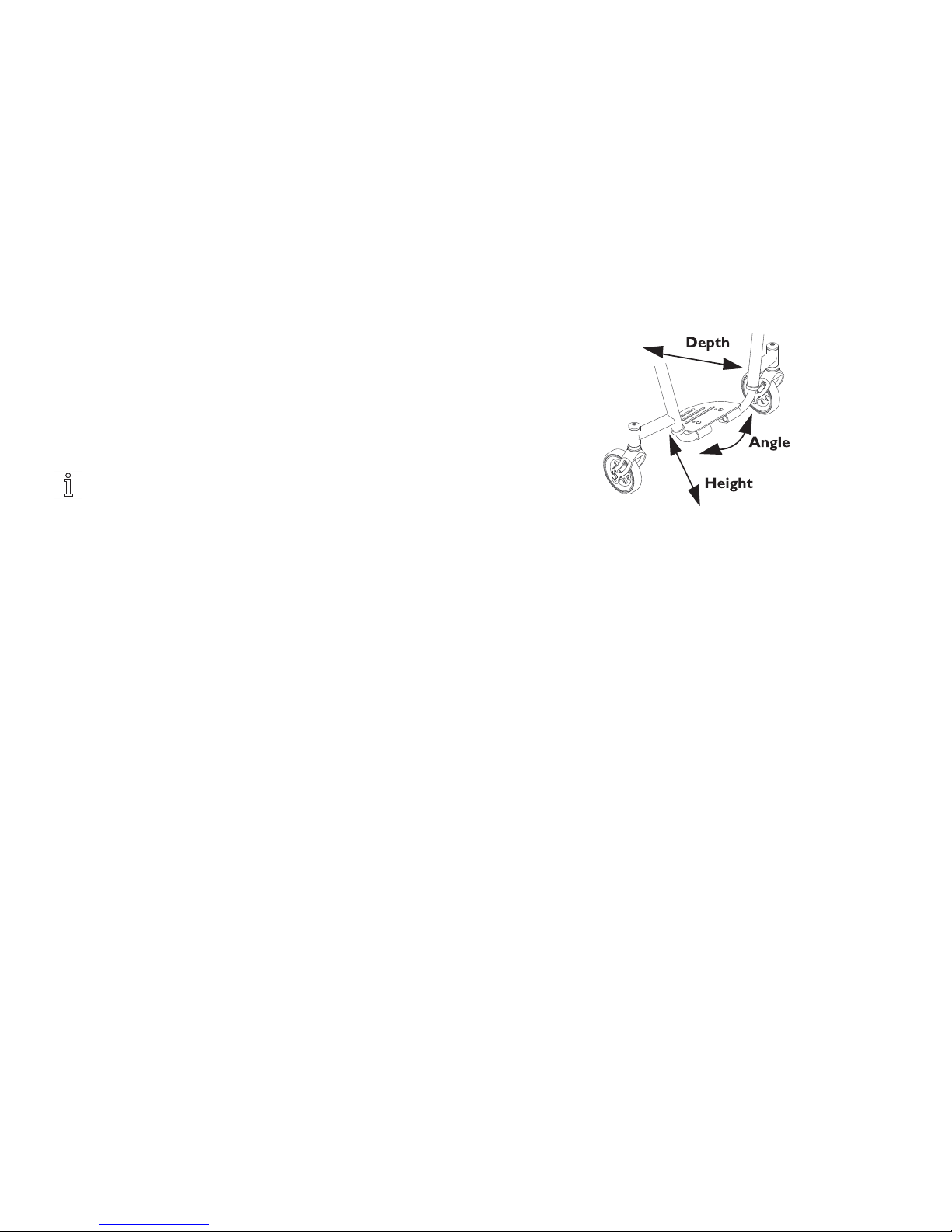
Service
AdjustingFootplateAngle
1.Loosen,butdonotremovethetwomountingscrewsEand
locknuts(notshown)thatsecurethefootplateDtothefootrest
tubesC.
2.PositionthefootplateDtothenecessaryangletoaccommodate
theuser.
3.TightenthetwomountingscrewsEandlocknuts.
Thelocknutsshouldlieinthechannelofthefootplateclamp.
AdjustingFootplateDepth
1.RemovethetwomountingscrewsEandlocknuts(not
shown)thatsecurethefootplateDtothefootresttubesC.
ObservetheangleofthefootplateDforreinstallation.
2.MovethefootplateDtooneoftwomountingpositionsFto
accommodatetheuser.
3.UsingthetwomountingscrewsEandlocknuts,securethe
footplateDtothefootresttubesC.
Thelocknutsshouldlieinthechannelofthefootplate
halfclamp.
5.17Installing/Removing/AdjustingSwivel
Anti-Tip
Removing
1.LoosensetscrewsConanti-tipreceiversB.
2.Slidetheswivelanti-tipAoutofthereceiversB.
Installing/DepthAdjustment
1.LoosensetscrewsConanti-tipreceiversB.
2.Slidetheswivelanti-tipAintotheanti-tipreceiversB.Position
swivelanti-tipAsoitisevenwithwheelsonchairorextends
beyondthem.TightensetscrewsC.
AdjustingHeight
1.Toadjusttheheightoftheswivelanti-tipA,removedustcover
andloosensetscrewConswivelanti-tipcasterassembly.
2.Setanti-tipcasterwheeltodesiredheight.TightensetscrewC
andreinstalldustcover.
1171801-A61

TopEnd
®
Terminator™Series
–Detailviewfromrearofwheelchair.
5.18ElastomersandSuspension
WARNING!
–Afteranyadjustments,repairorserviceandbefore
use,makesureallattachinghardwareistightened
securely.Otherwiseinjuryordamagemayoccur.
–Theperformanceofthewheelchairwillbeaffected
ifelastomersarenotthesameonbothsidesofthe
wheelchair.
ReplacingRearElastomers
Outsideof
Wheelchair
Frame
Insideof
Wheelchair
Frame
1.UseanallenwrenchtoholdtheouterallenscrewA.
2.WhileholdingtheouterallenscrewAinposition,removethe
innerallenscrewBfromthepivotpinC.
3.UsetheallenwrenchtopushthepivotpinCwithouterallen
screwAoutofthemountingholeD.
4.RemovetheexistingelastomerE.
621171801-A

Service
5.PositionthenewelastomerEbetweentherecessFintheaxle
bracketGandtherecessFinthesuspensionbaseH.
6.CompressandholdtheelastomerEbetweentheaxlebracket
GandthesuspensionbaseH.
7.InsertthepivotpinCintothemountingholeD.
8.InstalltheouterallenscrewAintothepivotpinC.
9.Useanallenwrenchtoholdtheouterallenscrewinposition.
10.WhileholdingtheouterallenscrewA,installtheinnerallen
screwBintothepivotpinC.Tightensecurely.
11.Releasewhendesiredspeedisachieved.
ReplacingFrontElastomers
CAUTION!
–DONOTuseexcessiveforcewhenremoving/installing
thethreadedsleevefrom/ontothefork.Damageto
thethreadedsleevemayoccur.
1.Usingtwoallenwrenches,turninoppositedirectionsand
removeonemountingscrewAfromforkB.
–Onemountingscrewwillnotturn.
2.RemovethethreadedsleeveCandmountingscrewassembly
fromtheforkB.DONOTuseexcessiveforce.
3.RemovetheexistingelastomerDfromtheforkB.
4.InstallnewelastomerDdeterminedinSTEP1intoforkB.
5.Alignthemountingholesintheupperandlowerportionofthe
forkB.
6.ReinstallthreadedsleeveCandmountingscrewassembly.DO
NOTuseexcessiveforce.
CAUTION!
–UseLoctite242™whenreinstallingthemounting
screwAintothethreadedsleeveC,otherwise
theforkBcanbecomedisassembled.Possible
injuryordamagecouldoccur.
7.ApplyLoctite242tothemountingscrewA.
8.ReinstallthemountingscrewAintothethreadedsleeveCand
tightensecurely.
1171801-A63

TopEnd
®
Terminator™Series
6Troubleshooting
6.1Troubleshooting
VeersRight
VeersLeftSluggishTurnor
Performance
CastersFlutterSqueaksand
Rattles
Looseness
inChair
Solutions
XXXX
Checktiresforcorrectand
equalpressure.
XXXX
Checkforloosestemnuts.
XX
Checkspokesandnipples.
XXX
Checkthatbothcasterscontact
thegroundatthesametime.
XXX
Checktoein/toeout.
641171801-A

Maintenance
7Maintenance
7.1Maintenance
MaintenanceSafetyPrecautions
WARNING!
–Afteranyadjustments,repairorserviceandbefore
use,makesureallattachinghardwareistightened
securely.Otherwiseinjuryordamagemayresult.
–DONOTovertightenhardwareattachingtothe
frame.Thiscouldcausedamagetotheframetubing.
Somecountriesrequireproductreturnedforservicebe
cleanedandsanitized.Pleaseconsultyourdealerpriorto
returningproduct.
SuggestedMaintenanceProcedures
1.Beforeusingyourwheelchair,makesureallnutsandboltsare
tight.Checkallpartsfordamageorwearandreplace.Checkall
partsforproperadjustment.
2.Keepquick/quad-releaseaxlesfreeofdirtandlinttoensure
positivelockingandproperoperation.Referto4.7Adjusting
Quick-ReleaseAxles,page34or4.8AdjustingQuad-Release
Handles,page35.
WARNING!
–DONOTuseWD-40®,3-in-1oil,orother
penetratinglubricantsonquick-releaseaxles
orcamberinserts.Otherwise,bindingand/or
damagetothewheelchaircanoccur.
3.Clean/oilquick-releaseaxlesandcamberinsertsonceaweek
withaTeflon®lubricant.
WARNING!
–DONOTusethewheelchairunlessithasthe
propertirepressure(p.s.i.).DONOToverinflate
thetires.Failuretofollowthesesuggestions
maycausethetiretoexplodeandcausebodily
harm.Therecommendedtirepressureisonthe
sidewallofthetire.
4.Recommendedtirepressureislistedonthesidewallofthetire.
CAUTION!
–Aswithanyvehicle,thewheelsandtiresshould
becheckedperiodicallyforcracksandwear,and
shouldbereplacedifdamaged.
5.Thewheels,castersandtiresshouldbecheckedperiodicallyfor
cracksandwear,andshouldbereplacedifdamaged.Contact
aqualifiedtechnicianorInvacarecustomersupportatthe
telephonenumbersonthebackofthismanual.
6.Regularlycheckforloosespokesinthefrontandrearwheels.
Ifloose,havethemadjusted.Contactaqualifiedtechnicianor
Invacarecustomersupportatthetelephonenumbersonthe
backofthismanual.
7.Periodicallycheckhandrimstoensuretheyaresecuredtothe
rearwheels.Referto5.8HandrimReplacement,page53.
8.Periodicallyadjustwheellocksastireswear.Referto5.13
WheelLockAdjustment/Replacement,page57.
9.Periodicallycheckcasterwheelbearingstomakesurethey
arecleanandfreefrommoisture.UseaTeflon®lubricantif
necessary.
10.Checkupholsteryforsagging,ripsortears.
11.Cleanupholsterywithmildsoapandwater.
1171801-A65

TopEnd
®
Terminator™Series
8Options
8.1Options
Installing/AdjustingtheFold-inSideguards
InstallingtheFold-inSideguards
1.PlacetheclampAaroundthewheelchairframeB.
2.InserttheboltthroughtheclampAandtightentoattachthe
clampAtothewheelchairframeB.
3.PlacethesideguardclampDaroundthebackpostEbysliding
thesideguardclampDontothebackpostE.
4.InserttheboltthroughthesideguardclampDandsideguard
Candtightensecurely.
Ifsideguardwillnotpivotfreely,boltthroughsideguard
clampDandsideguardCistootight.Tocorrect,loosen
bolt.
Ifsideguardrattles,boltthroughsideguardclampDand
sideguardCistooloose.Tocorrect,tightenbolt.
Fold-insideguardshouldbeabletobemovedvertically(Detail“A”)
andhorizontally(Detail“B”).
DETAIL“A”
661171801-A

Options
DETAIL“B”
AdjustingtheFold-InSideguardsHeight
1.Liftsideguardtoalevelposition(Detail“A”).
2.RemoveboltfromsideguardclampDandsideguardC.
3.AdjustsideguardCtodesiredheight.
4.InsertboltthroughsideguardclampDandsideguardC.
5.Tightensecurely.
6.Repeatforoppositeside.
Installing/RemovingtheRemovableSideGuards
InstallingtheRemovableSideGuards
1.LoosentwomountingscrewsAinsideguardB.
2.AttachsideguardclampCtothebackposts.
3.TightentwomountingscrewsAsecurely.
RemovingtheRemovableSideGuards
1.LoosentwomountingscrewsAinsideguardB.
2.RemovesideguardclampCfrombackposts.
InstallingtheBolt-onPushHandles
1171801-A67

TopEnd
®
Terminator™Series
Usingthemountingscrewattachthebolt-onpushhandlestothe
backcanes.
Installing/AdjustingtheAdjustablePushHandles
ToInstall:
1.LoosethetwomountingscrewsAinthepushhandleclampB.
2.AttachadjustablepushhandleCtobackcanebyinsertingthe
backcaneintothepushhandleclampB.
3.TightenthetwomountingscrewsAinthepushhandleclampB.
4.InserttheadjustablepushhandleCintothepushhandleclamp
B.
5.Repeatforoppositeside.
ToAdjust:
1.InsertadjustablepushhandleCintothepushhandleclampB.
2.Adjusttodesiredheight.
3.FlipleverDtosecureadjustablepushhandleC.
4.Repeatforoppositeside.
681171801-A

Warranty
9Warranty
9.1WarrantyInformation
UnitedStateLimitedWarranty
PLEASENOTE:THEWARRANTYBELOWHASBEENDRAFTEDTOCOMPLYWITHFEDERALLAWAPPLICABLE
TOPRODUCTSMANUFACTUREDAFTERJULY4,1975.
ThiswarrantyisextendedonlytotheoriginalpurchaserwhopurchasesthisproductwhennewandunusedfromInvacare
oradealer.Thiswarrantyisnotextendedtoanyotherpersonorentityandisnottransferableorassignabletoany
subsequentpurchaserorowner.Coverageunderthiswarrantywillenduponanysuchsubsequentsaleorothertransferof
titletoanyotherperson.
Thiswarrantygivesyouspecificlegalrightsandyoumayalsohaveotherlegalrightswhichvaryfromstatetostate.
Invacarewarrantstheframeswhenpurchasednewandunusedtobefreefromdefectsinmaterialsandworkmanshipfor
aperiodoffive(5)yearsfromthedateofpurchasefromInvacareoradealer,withacopyoftheseller’sinvoicerequired
forcoverageunderthiswarranty.
Invacarewarrantstheupholsteredmaterials(seatandback)andremainingcomponentsofthisproductwhenpurchasednew
andunusedtobefreefromdefectsinmaterialsandworkmanshipforaperiodofsixty(60)monthsfromdateofpurchasefrom
Invacareoradealer,withacopyoftheseller’sinvoicerequiredforcoverageunderthiswarranty.Ifwithinsuchwarranty
periodsanysuchproductshallbeproventobedefective,suchproductshallberepairedorreplaced,atInvacare’soption.This
warrantydoesnotincludeanylabororshippingchargesincurredinreplacementpartinstallationorrepairofanysuchproduct.
Invacare’ssoleobligationandyourexclusiveremedyunderthiswarrantyshallbelimitedtosuchrepairand/orreplacement.
Forwarrantyservice,pleasecontactthedealerfromwhomyoupurchasedyourInvacareproduct.Intheeventyoudonot
receivesatisfactorywarrantyservice,pleasewritedirectlytoInvacareattheaddressatthebottomofthispage.Provide
dealer’sname,address,theproductmodelnumber,dateofpurchase,indicatenatureofthedefectand,iftheproductis
serialized,indicatetheserialnumber.Donotreturnproductstoourfactorywithoutourpriorconsent.
1171801-A69

TopEnd
®
Terminator™Series
LIMITATIONSANDEXCLUSIONS:THEFOREGOINGWARRANTYSHALLNOTAPPLYTOSERIALNUMBERED
PRODUCTSIFTHESERIALNUMBERHASBEENREMOVEDORDEFACED,PRODUCTSSUBJECTEDTONEGLIGENCE,
ACCIDENT,IMPROPEROPERATION,MAINTENANCEORSTORAGE,PRODUCTSMODIFIEDWITHOUTINVACARE’S
EXPRESSWRITTENCONSENTINCLUDING,BUTNOTLIMITEDTO,MODIFICATIONTHROUGHTHEUSE
OFUNAUTHORIZEDPARTSORATTACHMENTS;PRODUCTSDAMAGEBYREASONOFREPAIRSMADETO
ANYCOMPONENTWITHOUTTHESPECIFICCONSENTOFINVACARE,ORTOAPRODUCTDAMAGEDBY
CIRCUMSTANCESBEYONDINVACARE’SCONTROL,ANDSUCHEVALUATIONWILLBESOLELYDETERMINEDBY
INVACARE.THEWARRANTYSHALLNOTAPPLYTONORMALWEARANDTEARORFAILURETOADHERETO
THEPRODUCTINSTRUCTIONS.
THEFOREGOINGEXPRESSWARRANTYISEXCLUSIVEANDINLIEUOFANYOTHERWARRANTIESWHATSOEVER,
WHETHEREXPRESSORIMPLIED,INCLUDINGTHEIMPLIEDWARRANTIESOFMERCHANTABILITYANDFITNESS
FORAPARTICULARPURPOSE,ANDTHESOLEREMEDYFORVIOLATIONSOFANYWARRANTYWHATSOEVER,
SHALLBELIMITEDTOREPAIRORREPLACEMENTOFTHEDEFECTIVEPRODUCTPURSUANTTOTHETERMS
CONTAINEDHEREIN.THEAPPLICATIONOFANYIMPLIEDWARRANTYWHATSOEVERSHALLNOTEXTEND
BEYONDTHEDURATIONOFTHEEXPRESSWARRANTYPROVIDEDHEREIN.INVACARESHALLNOTBELIABLE
FORANYCONSEQUENTIALORINCIDENTALDAMAGESWHATSOEVER.
SOMESTATESDONOTALLOWTHEEXCLUSIONORLIMITATIONOFINCIDENTALORCONSEQUENTIAL
DAMAGE,ORLIMITATIONOFHOWLONGANIMPLIEDWARRANTYLASTS,SOTHEABOVEEXCLUSIONAND
LIMITATIONMAYNOTBEAPPLICABLE.
THISWARRANTYSHALLBEEXTENDEDTOCOMPLYWITHSTATE/PROVINCIALLAWSANDREQUIREMENTS.
701171801-A

Warranty
9.2European,Australian,andNewZealand
LimitedWarrantyInformationandCustomer
Service
Termsandconditionsofthewarrantyarepartofthegeneraltermsandconditionsparticulartotheindividualcountriesinwhichthisproduct
issold.
Asia
1LentonPlace,P.O.Box5002,NorthRocks,NSW2151
Tel:6128895330Fax:61288395331
asiasales@invacare.comwww.invacare.com
Ireland:
InvacareIrelandLtd,Unit5SeatownBusinessCampus,SeatownRoad,
Swords,CountyDublin-Ireland
Tel:(353)18107084,Fax:(353)18107085
ireland@invacare.com,www.invacare.ie
Australia
1LentonPlace,P.O.Box5002,NorthRocks,NSW2151
Tel:1800460460Fax:0288395353
sales@invacare.com.au,www.invacare.com.au
NewZealand
4WestfieldPlaceP.O.Box62–124Mt.WellingtonAuckland
Tel:0800468222,Fax:0800807788
sales@invacare.co.nz,www.invacare.co.nz
Canada
570MathesonBlvd.E.Unit8Mississauga,OntarioL4Z4G4
Tel:(1)8006685324,Fax:(1)8006685478
infocanada@invacare.com,www.invacare.ca
EuropeanDistributorOrganisation:
Invacare,Kleiststraße49,D-32457PortaWestfalica
Tel:(49)(0)5731754540,Fax:(49)(0)5731754541
edo@invacare.com,www.invacare.eu.com
UnitedKingdom:
InvacareLimited,PencoedTechnologyPark,Pencoed,
BridgendCF355HZ
SwitchboardTel:(44)(0)1656776200,Fax:(44)(0)1656776201
CustomerservicesTel:(44)(0)1656776222,
Fax:(44)(0)1656776220
UK@invacare.com,www.invacare.co.uk
1171801-A71

InvacareCorporationwww.invacare.comandwww.topendchair.com
USA
OneInvacareWay
Elyria,OhioUSA
44036–2125
(800)333–6900
Manufacturedby:
TopEndSportsandRecreationProducts
450163rdCircleNorth
PinellasPark,Florida
(727)522–8677
(800)532–8677
EURepresentative:KüschallAG,Benkenstrasse260,CH-4108
Witterswil
1171801-A2013-05-22
*1171801A*
MakingLife’sExperiencesPossible™
 Loading...