

Invacare®ScanBed 750
TM
User Manual (GB)
Brugermanual (DK)
Bruksanvisning (SE)
Brukerveiledning (NO)
Käyttöohje (FI)
Bedienungsanleitung (DE)
Gebruiksaanwijzing (NL)
Manuel d’utilisation (FR)
Manual del usuario (ES)
Manuale d’uso (IT)

5
GB
Table of contents
User part ...................................................6
1. General information ......................................6
2. Operation of the SB750
TM
..................................7
Technical part ..............................................10
3. Information .............................................10
4. Receiving the SB750
TM
....................................11
5. Fitting the accessories ....................................13
6. Disassembly/assembly of the SB750
TM
.......................15
7. Wiring .................................................17
8. Order numbers for accessories. . . . . . . . . . . . . . . . . . . . . . . . . . . . . 19
9. Maintenance and check-ups ...............................21
10. Beds equipped with accumulator back up ....................21
11. Maintenance chart .......................................22
12. Trouble-shooting the electrical system ......................23
13. Lubrication plan .........................................23
14. Cleaning ...............................................24
15. Technical specifications ...................................24
16. Electrical data ...........................................25
17. Weight ................................................26
18. Disposal ................................................26

6
User part
Congratulations on your choice of Invacare® EC-Høng’s SB750TM nursing bed.
x The bed has been developed for patients over 12 years of age requiring care in a nursing home or
home care nursing.
x The bed combines excellent stability and ergonomic design with easy disassembly and operation.
x The unique backrest return of the bed provides the patient with excellent comfort and the carer with ideal
conditions for an ergonomically correct working position.
In order to optimise the patient’s comfort, Invacare® recommends using a 12-cm mattress.
1. General information
The SB750TM bed fulfils all requirements regarding maximum distances. However, if the bed
is used for the care of patients with small body dimensions, it must be especially noted that there
is a risk of such a patient slipping through the openings between the side rails or through the
opening between the side rail and the mattress support.
The bed must not be used by patients under 12 years of age, or by patients with body size
equivalent to an average 12 year old or smaller.
The bed, in combination with side rails, must not be used for persons under 45 kg or under 150
cm´s height, or for persons that are restless (spasms) or confused, unless
a professional risk assessment has taken place and been accepted, or
a correctly installed safety cover on the side rails are used.
When using side rails and the according safety cover, it is essential to ensure correct fitting -
otherwise there is danger of entrapment / suffocation between mattress support, side
rail and bed end!
If the bed is used by restless (spasms) or confused persons, an ACP box can be used for blocking
the hand control functions, and / or a limitation cross bar installed under the leg section of the
mattress support. This cross bar will prevent the leg section from being lowered below the level of
the mattress support, thereby reducing the opening between leg section and bed end.
Ensure the bed is adjusted to it’s lowest position before leaving the bed unattended - thereby the
effect of fall-down / entrapment accidents is reduced.
Invacare® accepts no liability for any use, change or assembly of the product
other than as stated in this User’s Manual.
When entering or exiting the bed, the height adjustment should be used. Furthermore, the backrest can be used as
support (yellow button on the hand control). However, the thigh- and leg section must be horizontal, otherwise,
there is risk of overloading of the mattress support.
The bed must be placed so that the height adjustment (up/down) is not obstructed by, for example, lifts or
furniture. Otherwise there is a risk for injury on user and/or equipment.
7
GB
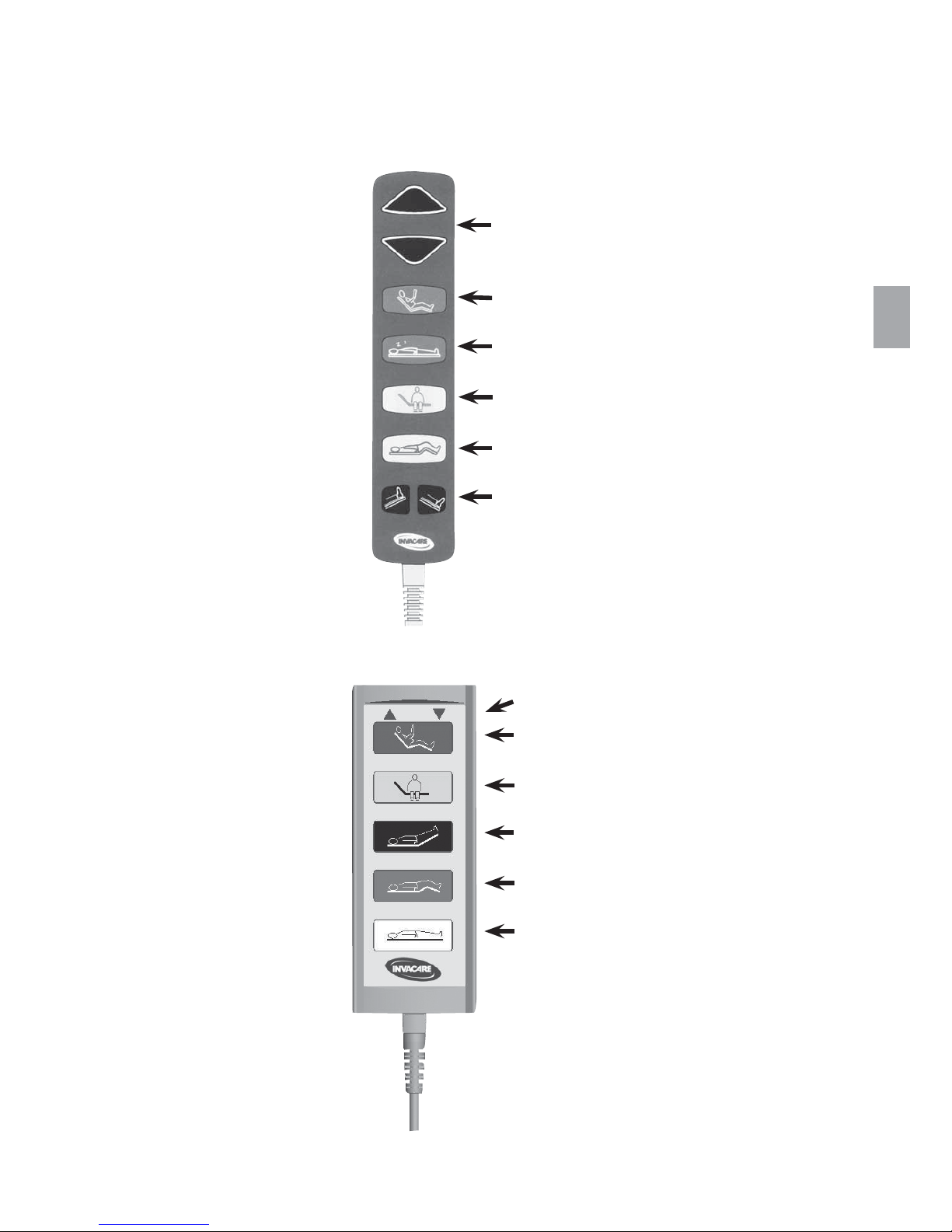
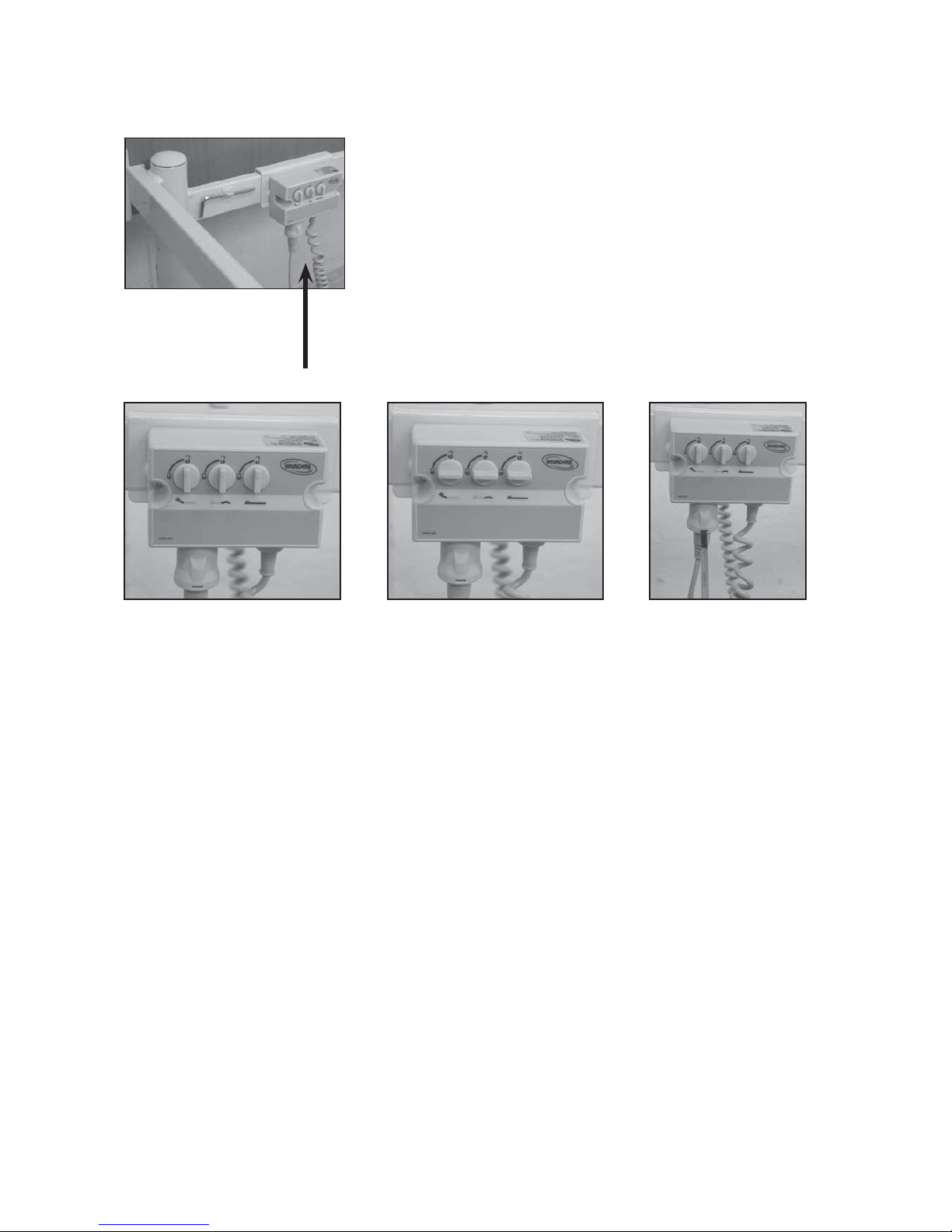
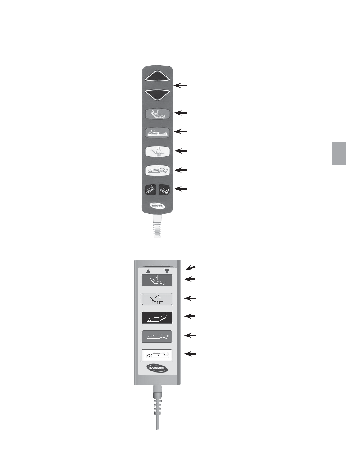
2. Operation of the SB750
TM
The bed can be equipped with this type of hand control (Soft Control):
Or with this type of hand control (HB 70):
Backrest
Sitting position
Leg section - electric
(not on beds with 3-sectioned mattress support
and manual adjustment of the leg section)
Thigh section
Height adjustment of the bed
UP/DOWN
Height adjustment of the bed
UP/DOWN
Sitting position, irrespective of
present position
Horizontal mattress support,
irrespective of present position
“Out of bed button”- Raises the backrest
and brings the thigh section to horizontal
Raises the thigh section and brings
the backrest to horizontal
Adjustment of leg section
UP/DOWN
(not on beds with 3-sectioned mattress
support and manual adjustment of the leg
section)
8
2)
1)
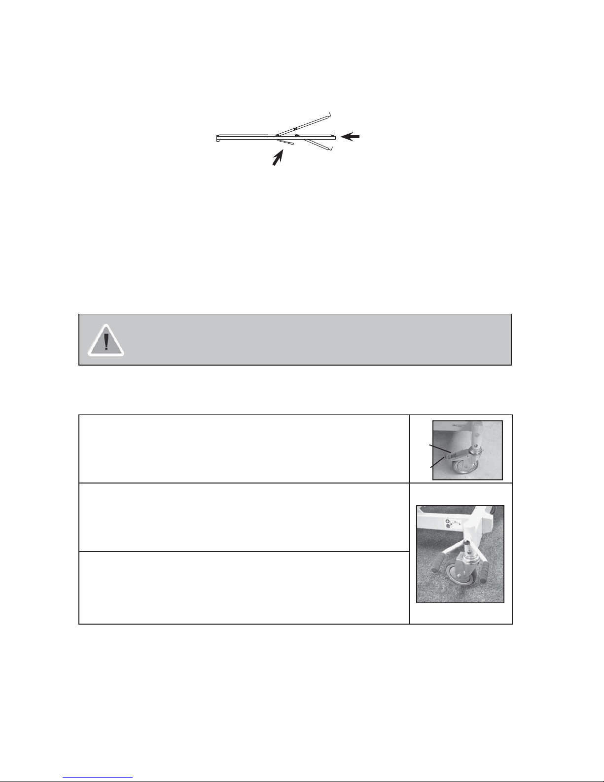
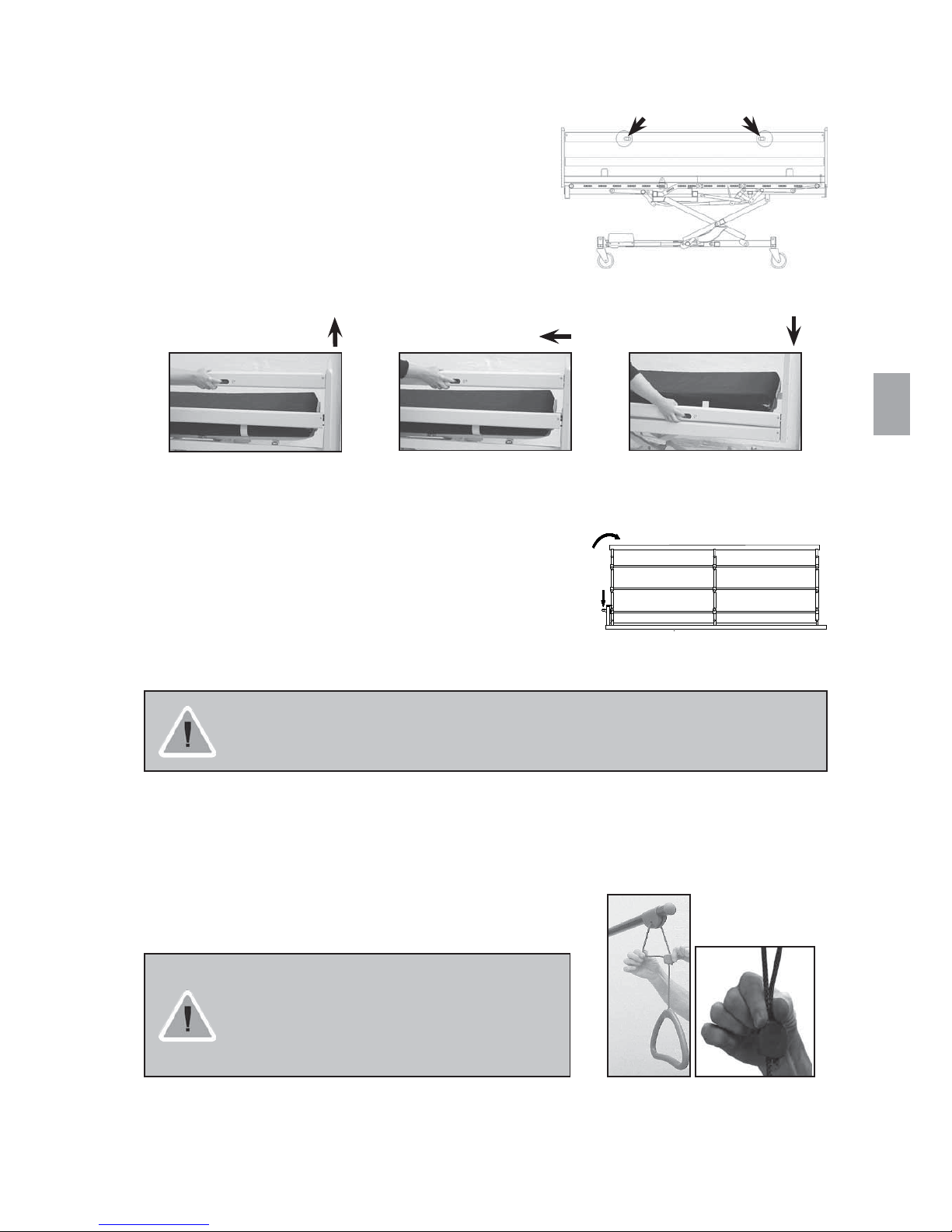
Operating the leg section on beds with gas springs
Lift the handle with one hand, while adjusting the leg section to the desired position with the other hand.
Release the handle.
Operating the leg section on SB750, 120 cm width, with Rastofix
To raise the leg section: Lift the leg section to desired height.
NB: Please ensure that both Rastofix brackets are correctly locked in place.
To lower the leg section: Lift the leg section slightly and lower to horizontal.
Always leave the bed in the lowest position. Otherwise there is a risk of squeezing due to
accidental lowering of the mattress support. A person can be seriously injured under the bed
during height adjustment.
Operating the braking castors
Operating castors without central braking system
When the bed is positioned correctly, at least one castor at the head end and one
castor at the foot end must be locked.
1) Braking: Step on the pedal.
2) Releasing the brake: Step on the release pedal.
Operating castors with central braking system
When the bed is positioned correctly, it must be locked.
1) Braking: If the brake is in neutral, step on the red pedal.
2) Releasing the brake: Step on the green pedal, until the brake is in neutral
position.
Operating the steerable castor
The SB750
TM
with central braking system may be equipped with a steerable castor.
The steerable castor is operated by means of the central braking pedal.
1) Activating the steering: If the brake is in neutral, step on the green pedal.
2) Deactivating the steering: Step on the red pedal, until the brake is in neutral
position.
Set-off from the castors might under special conditions appear at different types of absorbing floor covering including untreated or badly treated floors. In matters of doubt, Invacare® recommends to place a suitable kind of
protection between the castors and the floor.
Release handle
Leg section - manual
9
A B
GB
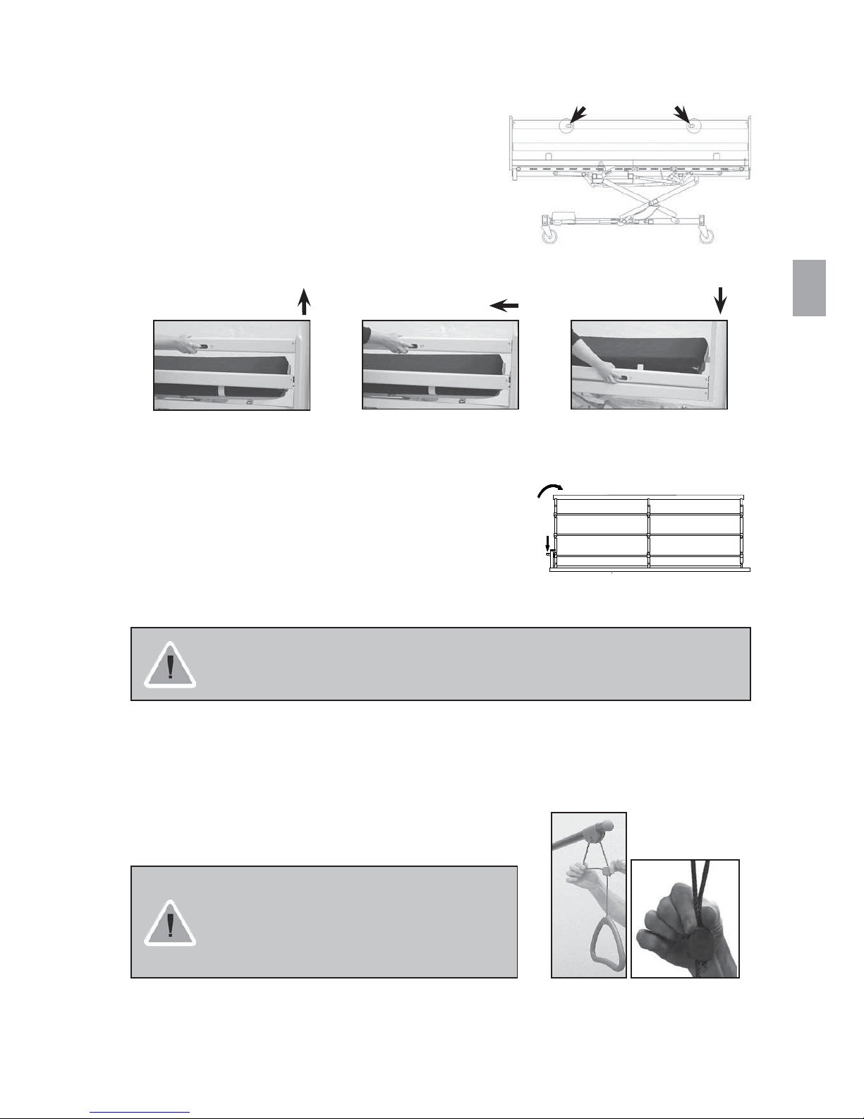
Operating the BRITT II/III/IV wooden side rail
The bed end may be equipped to lock the side rail at half height as
well as in the top position.
Normally the side rail can only be locked in top position.
Up: Pull up the top wooden side rail bar, until the locking pin locks
with an audible click.
Down: Lift the top wooden side rail bar and press the two locking
pins together. Lower the side rail.
Lift Release Lower
Operating the steel side rail
Up: Lift the top steel bar of the side rail towards the end with the
locking mechanism.
Down: Press the release button and pull the top bar of the steel
side rail away from the locking mechanism.
There is risk of entrapment of fingers on assembly and operation of the side rails.
Please ensure that the side rail locking system has engaged properly by pulling / pushing the upper bar.
Adjusting the height of the lifting pole handle
Loosen the cord as shown in fig. A. The lifting handle can now be
adjusted to the desired height.
Press the cord together as shown in fig. B and check that the cord
is locked in the cord lock by pulling the handle.
Position the lifting pole in such a way that the
handle is above the bed. If the lifting pole is used
while the handle has been turned away from the
bed - the bed can tip when the handle is used.
Locking pins
10
QA XXX
Technical part
Invacare® is certified according to DS/EN ISO 9001 and ISO 13485 which ensures that our
customers are always supplied with Invacare® products of uniform quality.
Throughout the entire production process our materials and products are quality controlled by the operators.
Furthermore there is a final test when the product is fully assembled.
The operator carrying out the final test, which comprises of checking all
moveable parts, motors/gas springs and castors, issues a QA number on the
product thereby confirming its quality.
If the product does not correspond to the quality demands of Invacare® it will be discarded.
If, contrary to our expectations, a problem should arise in connection with the delivered product, please
contact your Invacare® supplier.
3. Information
Please read the entire technical information section carefully before using or servicing the bed.
All indications of right and left are based on a patient lying on his back in the bed.
Please note that there may be sections in this User’s Manual, which are not relevant for your bed.
x The SB750
TM
is CE-marked in accordance with directive 93/42/EEC concerning Medical Apparatus.
x The SB750
TM
is tested without remarks by HMI according to EN 1970.
x SB750
TM
is tested and approved in accordance with NF (Norme Francaise).
x SB750
TM
is EMC tested and approved in accordance with EN 60601-1-2:93 by UL Demko.
x The motors and control unit of the SB750
TM
are approved according to EN 60601:1996-03.
x
SB750
TM
has undergone a risk analysis according to EN 14971.
Max. patient weight: 185 kg.
The hand control, control unit and motors are protected according to IP 66.
A lock cam must be used on the control unit - if not, Invacare®cannot guarantee the IP protection.
Electromagnetic interference between the bed and other electrical products can occur.
To reduce or eliminate such electromagnetic interference, increase the distance between the bed
and the products or switch them off.
This medical bed can be used together with medical electrical equipment connected to the heart
(intracardially) or the blood vessels (intravascularly), provided that following points are respected:
- The medical bed should be equipped with means for potential equalization connection marked
out by a symbol shown in the back of this manual.
- Medical electrical equipment should not be fixed on the bed’s metallic accessories
such as side rails, lifting pole, drip rod, bed ends ect.
In addition, the medical electrical equipment power supply cord should be kept clear
of the accessories or any other moving part of the bed.
Invacare®accepts no liability for any use, change or assembly of the product other
than as stated in this User’s Manual.
If the functions of the bed change, please send the bed immediately for a check-up according to the maintenance
chart, chapter 11.
11
GB
4. Receiving the SB750TM
To avoid condensation, the bed should not be used until it has reached a temperature of 10-50° C.
Check whether the bed shows any signs of damage. If the bed is damaged, see terms of delivery.
If the bed has been delivered in parts, it must be assembled.
Cf. chapter 6 “Disassembly/Assembly of the SB750
TM
”.
Check, that the connection between mattress support
and base frame is properly locked (cf. the picture).
Check that all plugs of the motors and hand control are
correctly connected to the control unit according to the
printed symbols.
The bed must have the brakes engaged during nursing of a patient in the bed.
Disconnect the plug from the mains before moving the bed. The cable must be kept clear off the
floor and the castors during transport.
Connect the SB750
TM
to the mains.
For ergonomic working position: Run the bed to approx. ½ height level.
Cf. chapter 2 “Operation of the SB750
TM
”.
Mount the accessories: Bed ends, side rails, lifting pole and bumper wheel.
Cf. chapter 5 “Fitting the accessories”.
Locked pin/
snap lock
Unlocked pin/
snap lock
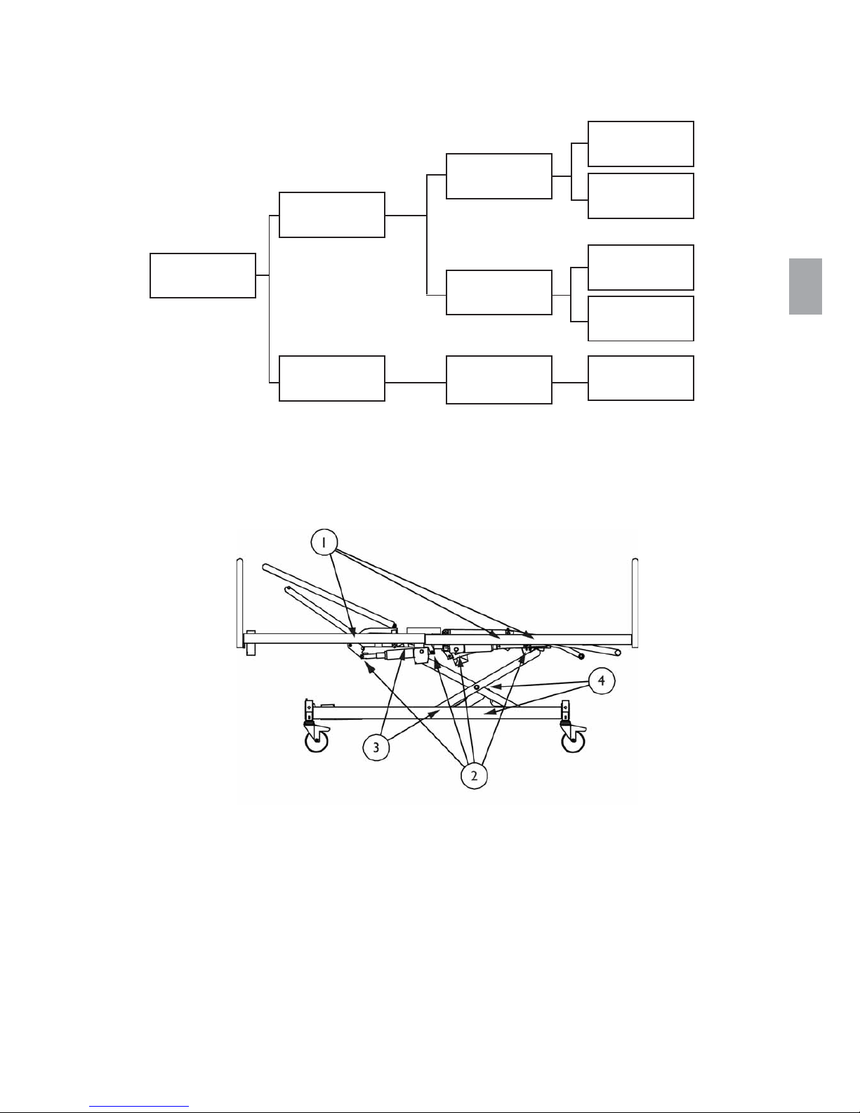
12
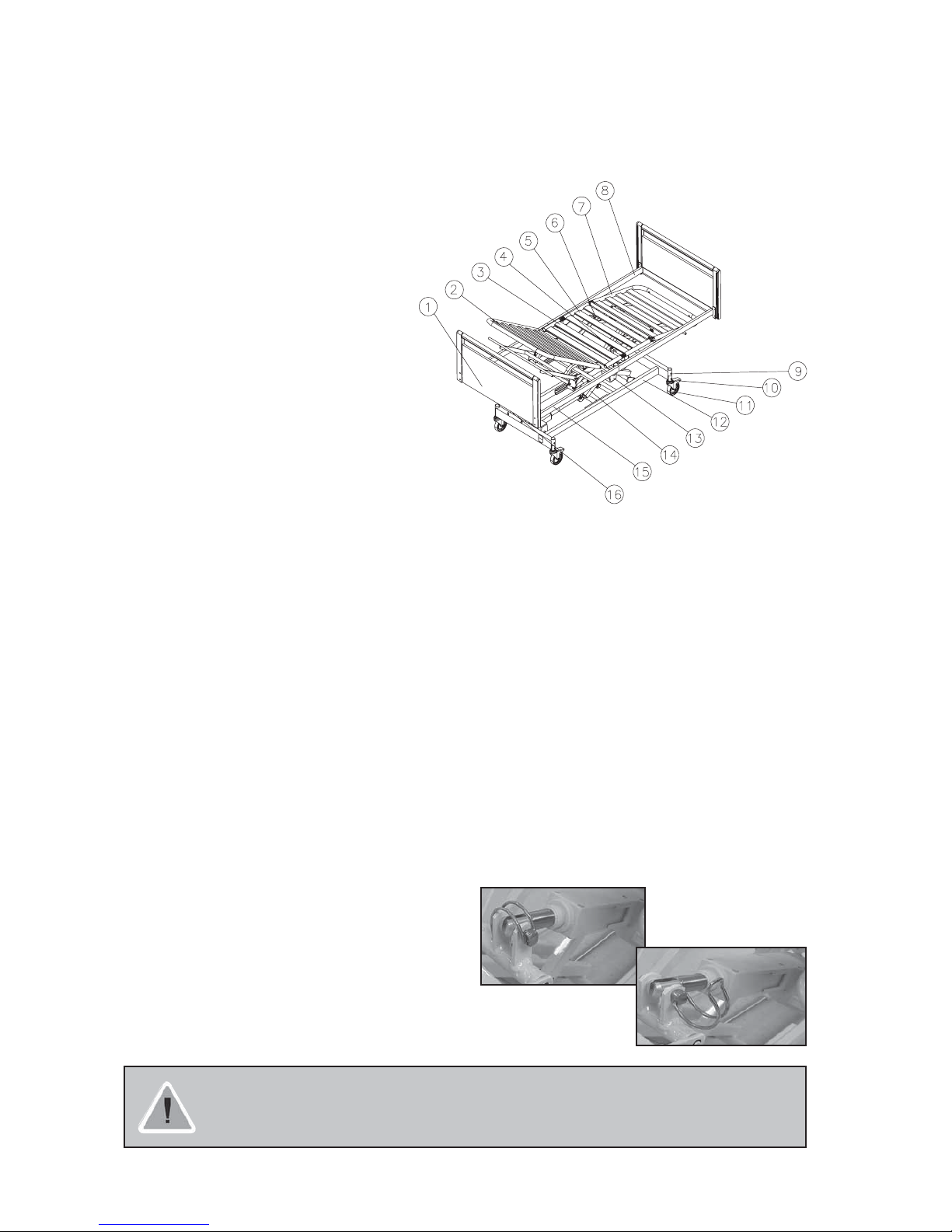
Parts of a standard bed
1. Allen key
2. Backrest
3. Seat section
4. 24 V motor, leg section or gas spring, leg section
5. Thigh section
6. 24 V motor, thigh section
7. Leg section
8. Top frame, foot end
9. Brake pedal for beds provided with central brake
10. Brake for beds provided with brake castors
11. Castor
12. Base frame
13. 24 V motor, backrest
14. Shear arms
15. Top frame, head end
16. Control unit
Accessories
x Battery box
x Fittings
x Bed end
x Wooden side rail
x Steel side rail
x Finger screw
x Lifting pole
x Bumper wheel
Emergency release of the mattress support parts
An emergency release of the mattress support is necessary
in the case of e.g. a power- or motor failure. An emergency
release of the height adjustment is NOT possible!
x Remove the plug from the mains before
emergency release of the mattress support.
x In an emergency the mattress sections are released
by pulling out the cotter pin from the motor/gas spring in question.
A minimum of 2 persons are required to release a mattress section. Both persons hold the
mattress section in locked position. One of them pulls out the cotter pin.
Both slowly lower the mattress section until it is completely down.
13
GB
5. Fitting the accessories
The tools necessary for mounting/dismounting the accessories of the SB750TM are an Allen key and an
adjustable wrench. The Allen key is kept on the inside of the cross bar at the head end of the top frame.
The Allen key is used for mounting/dismounting all fittings.
Mounting the mattress retainer
Mattress retainer is To be placed between third and To be placed between third and
squeezed down over the fourth lamella on backrest. fourth lamella on leg section.
mattress frame.
Mounting the bed end fittings
(If fittings have not been mounted in the factory)
1. Mount the 2 small fittings at the head end and tighten
them with the Allen key.
2. Mount the large fittings and the welded fitting at the
foot end and tighten them with the Allen key.
Mounting the PIGGY and ODA bed ends
Press the bed end into the U-profiles.
Mounting the FLEX III/KARIN III bed ends
Fasten the bed end to the bed end fittings with the bolts and tighten them with the Allen key.
Mounting the SANNE III bed end
Lift the bed end and place on the fittings at both sides. Push down to click into
place.
The locking pin must then be rotated and locked into postion.
Make sure that the bed end is locked.
Dismounting the SANNE III bed end
Pull the locking pin out, and turn it halfway.
Repeat at the other end. Pull the bed end up and out.
Mounting/dismounting the steel side rail
Mounting: Referring to labelling on the side rail
Tighten the side rail with 2 finger screws.
Dismounting: Loosen the finger screws, and remove the steel side rail.
14
A B C
Mounting the BRITT II/III/IV side rail
1. Raise the bed about 1/3.
2. Remove the protective tape from the locking pins at the ends of the side rail.
3. Mount one end at a time. Lift the lower wooden bar and guide the metal
bow to the bed end rail (A).
4. Press the locking pin of the side rail with a finger (B).
5. Guide the side rail to the bed end until the spring support snaps into place
and prevents the side rail from falling out of the bed end.
Repeat points 3 to 5 when mounting the other end of the side rail.
Dismounting the BRITT II/III/IV side rail
1. Raise the bed about 1/3. Lower the side rail.
2. Dismount one end at a time. Lift the lower wooden bar so that the spring support is visible.
3. Press the spring support down with a wrench or a screwdriver (C).
4. Hold the lower wooden bar. Lower the side rail, until the metal bow is free of the bed end rail.
Repeat points 2 to 4 when dismounting the other end of the side rail.
Fitting the lifting pole
Remove the plastic stopper in the lifting pole tube
in which the lifting pole is to be mounted.
Mount the lifting pole - the finger screw must be used.
Fitting the bumper wheel
Mount the bushing in the bumper wheel - and tighten it with a screw under the fitting.
Bumper wheels may not be mounted on SANNE bed ends.
Lifting pole
tube with
plastic stopper
Finger screw
Correctly mounted crossbar
The screws are tightenedThe limitation crossbar is placed here
Raise the leg section of the mattress support and the lifter arm, and mount the limitation crossbar.
Tighten both screws.
Mounting the limitation crossbar under the leg section
If the bed is used by restless (spasms) or confused persons a limitation cross bar installed under the
leg section of the mattress support. This cross bar will prevent the leg section from being lowered below the level ofthe mattress support, thereby reducing the opening between leg section and bed end.
15
3.
8.
10.
9.
7.
GB
6. Disassembly/assembly of the SB750
TM
Disassembly
1. Make sure that the castors have the brakes on.
2. Dismount all accessories.
3. Run the bed to the marked height level so that the cams on the base frame’s
guide way and the shear arms are opposite each other.
4. Disconnect the power supply.
5. Remove the locking cam from the control unit.
6. Disconnect the plugs of backrest, thigh and leg motors and check that the cables
are not caught in the base frame.
7. Remove the 2x2 finger screws in the side bars.
8. Pull the head top frame out of the inserts in the side bars to
stop and lower the section onto the floor.
9. Release the 2 lock fittings/snap locks on the foot top frame by
pulling out the locking pin and turning it to the right.
10. Lower the foot-section of the top frame and lift it off the base
frame. Remove the head
section of the top frame
from the base
frame.
11. Connect the base frame to
the mains again and lower
it completely.
Operating the built-in mattress support extension
The mattress support extension is mounted using the Allen key.
The Allen key is kept on the inside of the cross bar at the head end.
1. Remove the wooden side rails (cf. chapter 5).
2. Remove the 2 screws for fastening the fitting below the side
bar
by means of the Allen key.
3. Pull out the fitting so that it extends 16 cm, insert the 2 screws
again and retighten them.
4. Loosen the 2 screws below the mattress handle on the leg section,
pull the handle completely up, and retighten the screws.
5. Insert the mattress support extension.
Warning! In order to avoid entrapment / suffocation, it is essential to avoid
extending the bed ends without extentioning the mattress support accordingly.
See page 14: Mounting the limitation crossbar under the leg section
16
7.
4.1
5.
6.
4.2
Assembly
1. Make sure that the castors have their brakes on.
2. Connect the base frame to the mains.
3. Run the bed to the marked height level so that the cams (see picture 3, page 15) on the base frame’s
guide way and the shear arms are opposite each other.
4. Lift the foot end of the top frame so that the two 2 lock
fittings/snap locks fit onto the pins on the shearing arms. (4.1)
Make sure that the locking pin has clicked into place and is
locked (4.2). Then move the foot end of the top frame into
horizontal position.
5. Place the head end of the top frame in front of the base frame and
lower it down so that the plastic gliders slide into the guide way.
6. Lift the head end of the top frame and push it into the inserts
until it stops.
7. Screw the 2x2 finger screws into the side bars.
8. Connect the plugs of the backrest, thigh and leg motors to
the control unit, see section 7 regarding wiring.
9. Mount the accessories.
17
GB
7. Wiring
The wires are mounted from the bottom and through the case of the shaft end of the motor.
Guide the wires under the lamellas.
Mount the wires through the cable bow and further to the control unit.
These photos show a bed with 2 motors for the mattress support.
Control the wiring by operating all the motors of the bed to their outer positions.
When all wires have been correctly mounted, there is no squeezing risk of the wires.
It is normal that the wires after short usage loosen a bit.
18
ACP Box (optional)
The hand control can be locked by activating the switch on the ACP box
located in the head end of the bed.
To check if the locking function has been activated, depress a button on the
hand control.
Open Locked Removal of
safety lock
Replacement of hand control fitted to the ACP-Box
The white locking ring on the ACP box is depressed, after which the hand control cable can be removed.

19
GB
8. Order numbers for accessories
Article Dimensions Order no.:
WOODEN BED END
SANNE III (beech) ................................85 cm ................................020429.01
SANNE III (beech) ................................90 cm ................................020740.01
SANNE III (beech) ...............................105 cm ................................021953.01
SANNE III (beech) ...............................120 cm ................................021954.01
SANNE III (cherry / beech) .........................90 cm ................................021956.07
SANNE III, increased and lowered (beech, ) *) ..........85 cm ............................ 1451258-0101
SANNE III, increased and lowered (beech, ) *) ..........90 cm ............................ 1451257-0101
SANNE III, increased and lowered (beech, ) *) .........105 cm ............................1484403-0101
SANNE III, increased and lowered (beech, ) *) .........120 cm ............................1484404-0101
*) To be used with the LILLI III wooden side rail
FLEX III (beech) ..................................85 cm ................................020417.01
FLEX III (beech) ..................................90 cm ................................020737.01
PIGGY (beech / U-profiles) .........................85 cm ................................020431.01
PIGGY (beech / U-profiles) .........................90 cm ................................018940.01
ODA (beech / U-profiles) ...........................85 cm ................................020430.01
ODA (beech / U-profiles) ...........................90 cm ................................016609.01
Bed ends are available in other versions than the above mentioned - contact Invacare®
Side rails
Scala Basic Metal side rail (foldable) ..................................................... 1432784-1015
Scala Basic Plus Metal side rail (foldable, with plastic insert) .................................. 1432787-1015
Scala Medium Metal side rail (foldable) .................................................. 1432781-1015
Scala Decubi Metal side rail (foldable) ................................................... 1432793-1015
Metal side rail Model 5539, extended (foldable, with loose finger screws) ....................50.55390.D0/L+R
BRITT IV wooden side rail (high + 2.5 cm, beech) ......................................... 1427875-0101
BRITT IV wooden side rail (high + 2.5 cm, cherry) ......................................... 1427875-0102
BRITT IV wooden side rail (high + 2.5 cm, white pigmented) ................................ 1427875-0105
BRITT III wooden side rail (beech) .........................................................020434.01
BRITT III wooden side rail, short (beech) ....................................................021342.01
BRITT III wooden side rail (cherry) .........................................................020434.02
BRITT III wooden side rail, short (white pigmented) ...........................................021342.05
BRITT III wooden side rail (white pigmented) .................................................020434.05
BRITT II wooden side rail, extended (beech) .................................................019372.01
BRITT II wooden side rail, extended (cherry)
.................................................019372.02
BRITT II wooden side rail, extended (white pigmented) .........................................019372.05
LILLI III wooden side rail (beech) ....................................................... 1433812-0101
LILLI III wooden side rail (cherry) ...................................................... 1433812-0102
LILLI III wooden side rail, extended (beech) .............................................. 1434044-0101
Covering tubes for mattress support extension ..............................................017639.D0
SUPPORT HANDLES
Support handle ................................25x30 cm ...............................021964.D0
Support handle ................................40x50 cm ...............................021963.D0
Support handle ................................25x80 cm ............................ 1417510-1015
Support handle ................................40x30 cm ............................ 1417511-1015
Support handle ................................40x95 cm ............................ 1417512-1015
LIFTING POLE
Lifting pole ..........................................................................50.57600.D0
LIMITATION CROSSBAR
Limitation crossbar (prevents the leg section from being lowered below the level of the top frame) . 1510820-1015

20
Article Dimensions Order no.:
DRIP
Drip rod ............................................................................50.60030.D0
Drip rod (for mounting in lifting pole tube) .................................................50.60910.00
BUMPER WHEELS
Bumper wheels (one) ........................................................75 mm ....50.59600.00
Bumper wheels (one) .......................................................100 mm ....50.59610.00
Bumper wheels (one) .......................................................150 mm ....50.59640.00
Bumper wheels (one, vertical) ................................................100 mm ....50.59630.D0
MATTRESSES
Dacapo Standard (38 kg/m
3
cold foam, cotton cover) ...........................85x200x10 .......1421530
Dacapo Standard (38 kg/m
3
cold foam, cotton cover) ...........................90x200x10 .......1421531
Dacapo Standard (38 kg/m
3
cold foam, cotton cover) ..........................105x200x10 .......1421532
Dacapo Standard (38 kg/m
3
cold foam, cotton cover) ..........................120x200x10 .......1421533
Dacapo Basic (38 kg/m
3
cold foam, incontinence cover) ..........................88x200x12 .......1421551
Dacapo Basic (38 kg/m
3
cold foam, incontinence cover) ..........................83x200x12 .......1421552
Dacapo Basic (38 kg/m
3
cold foam, incontinence cover) ..........................88x183x12 .......1421555
Dacapo Basic (38 kg/m
3
cold foam, incontinence cover) ..........................83x183x12 .......1421556
Dacapo Basic Heavy user (3 coated 50/50/38 kg/m
3
cold foam, incontinence cover) . . 105x200x15 .......1484429
Dacapo Basic Heavy user (3 coated 50/50/38 kg/m
3
cold foam, incontinence cover) . . 120x200x15 .......1451262
Dacapo Organic (50 kg/m
3
Organic foam, egg tray shape, incontinence cover) .......85x200x12 .......1421572
Dacapo Organic (50 kg/m
3
Organic foam, egg tray shape, incontinence cover) .......90x200x12 .......1421573
Dacapo Combi (2 coated 50/38 kg/m
3
, Visco-elastic/cold foam, incontinence cover) ....85x200x14 .......1421489
Dacapo Combi (2 coated 50/38 kg/m
3
, Visco-elastic/cold foam, incontinence cover) ....90x200x14 .......1421490
Dacapo Square (2 coated 50/38 kg/m
3
, Organic foam/cold foam, incontinence cover) . . 83x200x14 .......1421515
Dacapo Square (2 coated 50/38 kg/m
3
, Organic foam/cold foam, incontinence cover) . . 88x200x14 .......1421516
Dacapo Top (50 kg/m
3
, Visco-elastic foam, incontinence cover) ....................85x200x6 .......1421587
Dacapo Top (50 kg/m
3
, Visco-elastic foam, incontinence cover) ....................90x200x6 .......1421588
It is possible to buy custom-fit insertion mattresses for extended beds.
LOW - SLUNG SET
Low-slung set with Ø75 mm braking castor .................................................021343.D0
SIDE RAIL COVERS
Scala Cover for Britt III, IV and Lilli III wooden side rail ..........................................1449412
Scala Cover for Britt III wooden side rail, short ................................................1449411
Scala Cover for Britt II and Lilli III wooden side rail, extended ....................................1493565
Scala Cover for Britt III, IV and Lilli III wooden side rail, net ......................................1449413
Scala Cover for Britt II and Lilli III wooden side rail, net, extended .................................1449415
Scala Cover for metal side rail, Basic .........................................................1449423
Scala Cover for metal side rail, increased .....................................................1449419
Scala Cover for metal side rail, extended .....................................................1449421
Safety Cover for Britt III, IV and Lilli III wooden side rail .........................................1511890
Safety Cover for Britt III wooden side rail, short ...............................................1513592
Safety Cover for Britt II and Lilli III wooden side rail, extended ....................................1511892
21
GB
9. Maintenance and check-ups
Service and maintenance of the SB750TM must only be performed by personnel who have received the
necessary instruction or training.
With normal daily use, service must be carried out according to the service schedule after 2 years use and
thereafter every second year.
When moving the bed, service must be carried out according to the service schedule.
When using Flex or Karin bed ends, which are made of a flexible type of wood, it will be necessary to tighten the
hexagon head screws at intervals other than described in the service schedule.
Note! The top frame must be supported during service inspections to prevent accidental lowering.
We recommend a safety test comprising the motors’ performance and mechanical state once a year.
Motors, hand control and control unit
These parts are serviced by exchanging the faulty part.
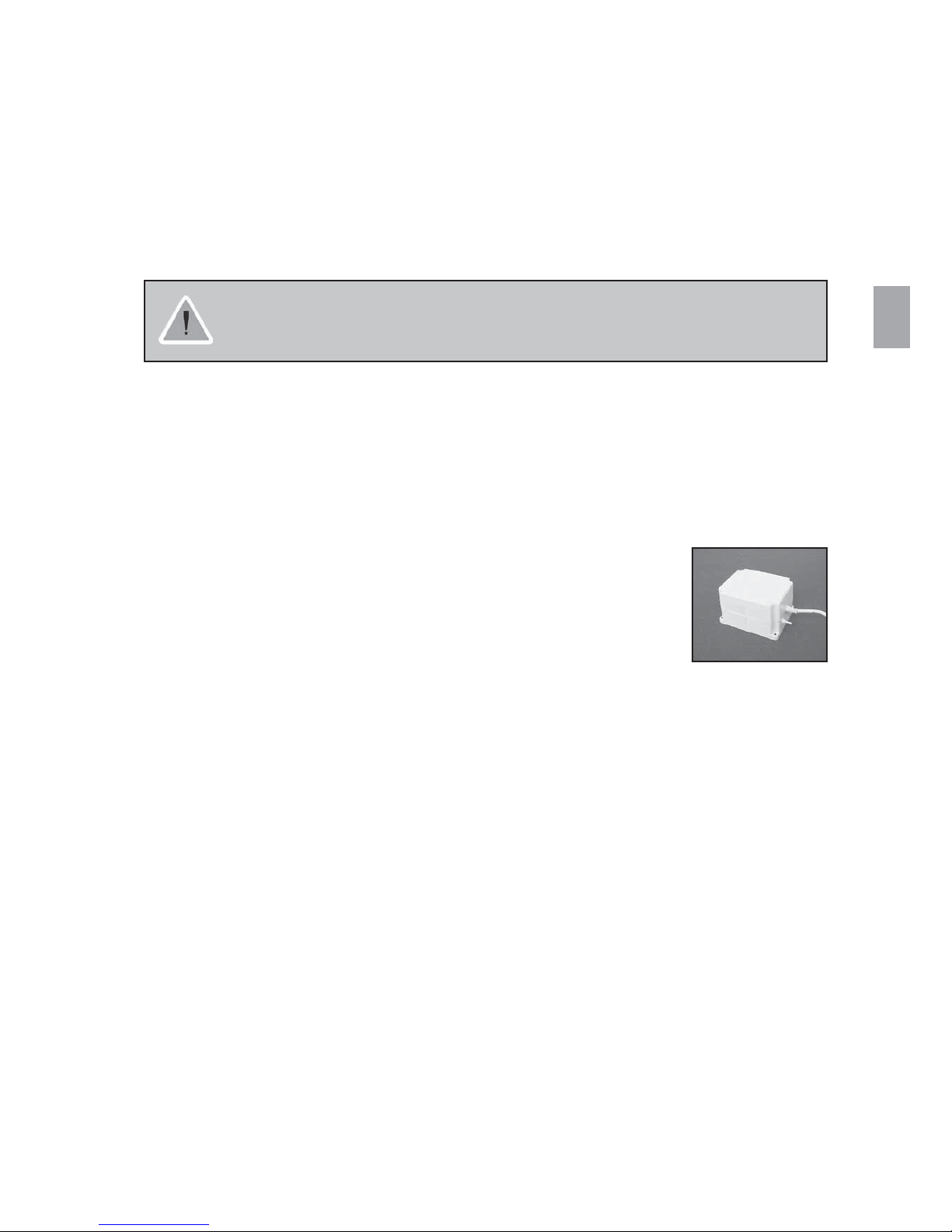
10. Beds equipped with accumulator back up
A bed with accumulator back up is equipped with an additional box next to
the control unit.
Preventive maintenance
The accumulators have to be exchanged after 4 years. Depending on how the
back up is used the exchange may have to take place earlier.
Frequent, sudden discharges reduce the back-up’s life.
We recommend the accumulator be tested at least once a year.
Accumulators are not damaged by continuous connection to the mains.
Exchanging the accumulators
Accumulators must be exchanged as sets and replaced with accumulators of the same type or mechanically
and electrically compatible accumulators:
The accumulators are delivered as a pair under order no.: 818323 (12V - 1,2 Ah).
Accumulators must be new and charged at least every 6 months for maintenance purposes.
Accumulators in a set must have identical production codes.
Prior to insertion make sure that the accumulator set is correctly connected cf. the drawing
(in the accumulator box), and that none of the connections are loose.
Warning
Old or faulty accumulators may generate an explosive gas mixture during charging.
The accumulator box is provided with vents to ensure adequate ventilation of the box.
The vents must not be blocked or covered, as this may result in pressure built-up and the risk of explosion.
Waste disposal
Old accumulators may be returned to Invacare
®
, alternatively they are disposed of like car batteries.

22
11. Maintenance chart
Service and maintenance of the SB750TM must only be performed by personnel who have received
the necessary instruction or training
S/N (located on mattress support): ___________________
Date: Initials:
Circlips, cotter pins and plastic fixing ring checked.
Screws tightened.
Weldings checked.
Side rail locking and moving system tested.
Castor fittings tightened.
Castor brakes checked.
Height adjustment motor checked.
Back rest motor checked.
Thigh section motor checked.
Leg section gas spring/motor checked.
Lead-in connections correctly suspended and
undamaged. Plugs undamaged.
Damaged coating repaired.
Lubrication according to the lubrication plan.
NB! The wooden side rails´ gliding system must not
be lubricated with oil - otherwise the wooden bars
will move sluggishly.
Accessories checked.
A service contract can be made in the countries, where Invacare® has its own sales company.
In certain countries Invacare® offers courses in service and maintenance of the SB750
TM
.
Spare parts lists and additional user manuals are available from Invacare®.
23
GB
12. Trouble-shooting the electrical system
Note! Make sure that the mains are connected.
13. Lubrication plan
We recommend lubricating the SB750TM according to the following instructions:
1. Lifting arm bearings - lubricate with oil
2. Motor/gas spring bearings - lubricate with oil
3. Gliders and guide ways - lubricate with grease
4. Shear arms and rollers shaft - lubricate with oil/grease
Lubricate with medically clean oil, e.g. KEW-WO 50, order no.: 813239 and grease, order no.: 1497607.
Motor plug not
connected
Sounds from the
relay
Defective motor
No motor sound
Motor does not
run
Defective control
unit
No relay sounds
Motor sounds
Piston rod does
not move
Defective motor
Defective hand
control
24
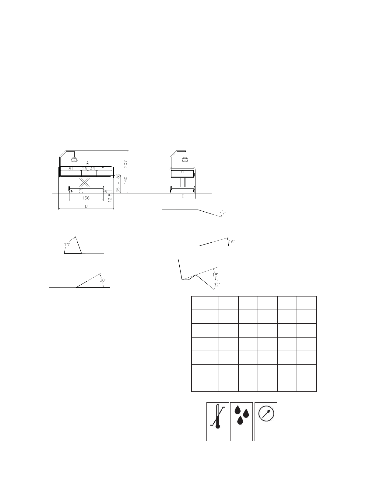
WxLABCD E
85x200 200 213 85 95 60
90x200 200 213 90 101 60
85x183 183 196 85 95 43
90x183 183 196 90 101 43
105x200 200 213 105 116 60
120x200 200 213 120 131 60
700 -
1.100 hPa
10 - 80%
-10 - 50°C
14 - 122°F
14. Cleaning
The SB750TM cannot withstand cleaning in washing machines nor flushing with a water jet. Use ordinary
disinfectioning detergents. Dry the bed after cleaning. Never use acids, alkalines or solvents. Please make sure the
power plug is removed from the socket outlet.
The back rest and the leg/thigh sections can be lowered onto the mattress support, which facilitates cleaning and
access to the control unit.
Important details for cleaning hand control, control unit and motors IP 66: Always clean with water and
brush. Water may be pressurised, but never use high-pressure cleaning or steam cleaning directly on the electrical
parts.
15. Technical specifications
All measurements are stated in cm. All angles are stated
in degrees. All measurements and angles are stated
without tolerances. Invacare® reserves the right to change
the stated measurements and angles without warning.
Transportation and storage conditions:
Temperature between -10° and 50° C
Humidity between 10 and 80 % RH
Pressure between 700 and 1.100 hPa

25
= 220 kg
GB
16. Electrical data
Voltage supply: 230 V AC/50 Hz.
Max. current input: 1,5 A.
Intermittent (periodic use of motors): 10% max. 6 min/h.
Max. accumulator capacity: 1,2 Ah.
Protection class: IP 66.
Output: 70 VA.
Sound level: 48 dB (A).
Double insulated, class II, type B.
Alternating current:
Direct current:
Max. load (SWL)
(Patient + mattress + siderail + lifting pole + other equipment).
The patient is not separated from the ground and the chassis.
Potential equalization.
The control unit has no contact breaker, disconnecting the plug is the only means of interrupting the power supply.
26
17. Weight
Measurement
Weight
85x200
90x200
105x200 120x200
Top frame, head, with mattress support 25 kg 34 kg 36 kg
Top frame, foot, with mattress support 25 kg 36 kg 39 kg
Base frame 40 kg 40 kg 42 kg
Complete bed, excluding accessories 90 kg 110 kg 117 kg
Bed end (SANNE III/FLEX III/KARIN III) 6 kg/pcs. 7 kg/pcs. 8 kg/pcs.
Wooden side rail (BRITT II/BRITT III) 7 kg/pcs. 7 kg/pcs. 7 kg/pcs.
Wooden side rail (BRITT IV) 8 kg/pcs. 8 kg/pcs. 8 kg/pcs.
Bed end (ODA/PIGGY) 6 kg/pcs. - -
Steel side rail 7 kg/pcs. 7 kg/pcs. 7 kg/pcs.
Lifting pole 6,5 kg 6,5 kg 6,5 kg
18. Disposal
This product has been supplied from an environmentally aware manufacturer that complies with the Waste
Electrical and Electronic Equipment (WEEE) Directive 2002/96/CE.
This product may contain substances that could be harmful to the environment if disposed of in
places (land fills) that are not appropriate according to legislation.
The »crossed out wheelie bin« symbol is placed on this product to encourage you to recycle
wherever possible.
Please be environmentally responsible and recycle this product through your recycling facility at
its end of life.

5
DK
Indholdsfortegnelse
Brugerdel ...................................................6
1. Generelt ................................................6
2. Betjening af SB750
TM
. . . . . . . . . . . . . . . . . . . . . . . . . . . . . . . . . . . . . . . 7
Teknisk del .................................................10
3. Information .............................................10
4. Ved modtagelse af SB750
TM
på opstillingsstedet ...............11
5. Montage af tilbehør ......................................13
6. Adskillelse/samling af SB750
TM
..............................15
7. Ledningsføring ..........................................17
8. Bestillingsnumre på tilbehør ...............................19
9. Vedligehold og eftersyn ...................................21
10. Specielt for senge med akkumulator back-up .................21
11. Serviceskema ...........................................22
12. Fejlsøgning i det elektriske system ..........................23
13. Smøreskitse ............................................23
14. Rengøring ..............................................24
15. Tekniske specifikationer ..................................24
16. Elektriske data ..........................................25
17. Vægt ..................................................26
18. Bortskaffelse ............................................26
6
Brugerdel
De har valgt en Invacare® EC-Høng’s SB750TM plejeseng.
x Sengen er udviklet til brugere over 12 år til pleje i hjemmet og på plejehjem.
x Sengen forener stabil konstruktion og ergonomisk design med nem adskillelse og betjening.
x Sengen sikrer ved hjælp af et unikt ryglæns-tilbageføringssystem en god liggekomfort for brugeren og
ideelle vilkår for plejeren ved nemmere forflytning.
For at optimere liggekomforten anbefaler Invacare® EC-Høng A/S, at en 12 cm madras anvendes.
1. Generelt
SB750TM opfylder alle krav til maximum afstande. Der må dog gøres opmærksom på, at hvis
sengen bliver brugt til mindre personer, er der en risiko for at glide ud igennem åbningerne for
enden af sengehestene eller igennem åbningerne imellem sengehestene og liggefladen.
Sengen må ikke bruges af patienter under 12 år eller af patienter,
hvis kropsstørrelse svarer til eller er mindre end en gennemsnits 12-årig.
Sengen med sengehest må ikke benyttes af personer, der vejer under 45 kg,
er under 150 cm´s højde eller er urolige og konfuse, medmindre:
en faglig vurdering og accept er foretaget, eller
et korrekt monteret sikkerhedsovertræk til sengehestene bliver anvendt.
Ved brug af sengehest og tilhørende overtræk er det vigtigt, at både sengehest og overtræk
monteres som angivet - i modsat fald er der fare for klemning / kvælning mellem
liggeflade, sengehest og gavle.
Hvis sengen anvendes af urolige eller konfuse personer, kan der med fordel anvendes en
ACP-boks, til låsning af håndbetjeningen, og/eller tværprofil til placering under sengens bendel.
Denne tværprofil vil så modvirke, at bendelen kan sænkes under overrammens niveau, og dermed
mindske åbningen mellem bendel og gavl.
Efterlad altid sengen i laveste position - dermed mindskes effekten af eventuelle faldulykker fra
liggefladen.
Invacare® påtager sig intet ansvar, hvis produktet anvendes, forandres eller sættes
sammen på anden vis end som angivet i denne brugsanvisning.
Ved ind- og udstigning af sengen kan sengens højdeindstilling med fordel bruges. Endvidere kan ryglænet anvendes
som støtte (gul knap på håndbetjeningen), dog skal sengens lår- og bendel være i horisontalstilling - i modsat fald er
der fare for overbelastning af liggefladen.
Sengen skal placeres, så højdejusteringen (op/ned) ikke generes af f.eks. personløftere eller møbler. Ellers er
der risiko for kvæstelser på bruger og/eller udstyr.
7
DK
2. Betjening af SB750
TM
Sengen kan være udstyret med denne type håndbetjening (Soft Control):
Eller med denne type håndbetjening (HB 70):
Højdeindstilling af seng
OP/NED
Siddeindstilling, uanset hvilken stilling
den starter fra
Liggefladen i vandret, uanset hvilken
stilling den starter fra
“Ud af sengen knappen”- Rejser
ryglænet og bringer lårdelen i vandret
Hæver lårdelen og bringer rygdelen
i vandret
Indstilling af bendel
OP/NED (findes ikke på senge med
3-delt liggeflade og manuel indstilling af
bendel)
Siddeindstilling
Bendel - elektrisk (findes ikke på senge med
3-delt liggeflade og manuel indstilling af bendel)
Lårdel
Højdeindstilling af seng
OP/NED
Ryglæn

8
2)
1)
Betjening af bendel på senge med gas fjedre
Løft i udløserhåndtaget med den ene hånd samtidig med at bendelen hæves til den ønskede stilling med den anden
hånd. Slip udløserhåndtaget.
Betjening af bendel på SB750, 120 bred med rastofix
For at hæve bendel: Løft i sengens bendel til ønsket højde.
For at sænke bendel: Løft en smule i sengens bendel og sænk til vandret.
Efterlad altid sengen i laveste position. Derved sikres imod klemning ved utilsigtet sænkning af
liggefladen. Der kan ske alvorlig skade på person, der opholder sig under sengen, mens sengens
højde justeres.
Betjening af bremsehjul
Betjening af hjul uden centralbremse
Når sengen er anbragt det rette sted, skal mindst et hjul i hovedende og et hjul i
fodende være bremset.
1) Brems: Træd på pedalen.
2) Udløs bremsen: Træd på pedalen.
Betjening af hjul med centralbremse
Når sengen er anbragt det rette sted, skal den være bremset.
1) Brems: Fra neutral stilling trædes på den røde pedal.
2) Udløs bremsen: Træd på den grønne pedal til neutral position.
Betjening af det retningsstyrede hjul
SB750
TM
med centralbremse kan være udstyret med et retningsstyret hjul.
Det retningsstyrede hjul betjenes fra centralbremsepedalen.
1) Aktiver retningsstyret: Fra neutral stilling trædes på den grønne pedal.
2) Deaktiver retningsstyret: Træd på den røde pedal til neutral position.
Sengehjulene kan under nogle forhold sætte mærker på enkelte typer gulv - f.eks. ubehandlede eller dårlige
trægulve. Hvis der opstår tvivl, anbefaler Invacare® at der lægges en beskyttelses plade mellem hjul og gulv.
Bendel - manuel
Udløserhåndtag
9
A B
DK
Betjening af BRITT II/III/IV træsengehest
Gavltræet kan være forberedt til, at sengehesten kan låses i halv
højde og i topposition.
Normalt er der kun mulighed for at låse sengehesten i topposition.
Op: Træk op i øverste træstav til kliklyd høres fra låsepalen.
Ned: Løft op i øverste træstav, pres derefter de 2 låsepaler
mod hinanden. Sænk sengehesten.
Løft op Udløs Sænk
Betjening af metalsengehest
Op: Træk/løft i øverste rør på metalsengehesten - mod den ende,
hvor låsesystemet sidder.
Ned: Tryk udløserknappen ned, mens der trækkes i det øverste rør
på metalsengehesten - væk fra udløsersystemet.
Der er klemrisiko af fingre ved montage og betjening af metalsengehestene. Det skal sikres,
at låsesystemet er gået korrekt i indgreb, ved at trække/skubbe den øverste overligger.
Ændring af galgehåndtagets højde
Snoren løsnes som vist på billede A, hvorefter galgehåndtaget
kan justeres til den ønskede højde.
Klem snorene sammen som vist på billede B og kontroller, at
snoren er fastlåst i snorlåsen ved at trække ned i galgehåndtaget.
Galgen skal sidde, så galgehåndtaget er inde
over sengen. Hvis galgen drejes ud over sengens
side - og galgen benyttes - kan sengen vælte.
Låsepaler

10
QA XXX
Teknisk del
Invacare® er certificeret i henhold til DS/EN ISO 9001 og ISO 13485. Dette sikrer vore kunder,
at produkter produceret hos Invacare® altid leveres i en ensartet kvalitet.
Gennem hele produktionen kvalitetkontrolleres vore emner og produkter af operatørerne. Når produktet er
færdigmonteret, foretages slutafprøvning.
Operatøren, der foretager denne slutafprøvning - som bl.a. indeholder kontrol
af alle bevægelige dele, motorer/gasfjedre og hjul, kvitterer ved at sætte sit
personlige QA-nummer på produktet.
Hvis produktet ikke lever op til Invacare® EC-Høng’s fastsatte kvalitetskrav, vil produktet blive kasseret.
Skulle der mod forventning opstå problemer med det leverede produkt, bedes henvendelse rettet til Invacare®
leverandøren.
3. Information
Læs hele den tekniske del igennem, inden sengen tages i brug eller serviceres.
Al angivelse af højre og venstre forudsætter, at man ligger på ryggen i sengen.
Vær opmærksom på, at der kan forekomme afsnit i denne brugsanvisning, der ikke er relevant for Deres seng.
x SB750
TM
er CE-mærket i henhold til Direktiv 93/42/EØF om medicinsk udstyr.
x SB750
TM
er testet uden anmærkninger hos HMI i h.t. EN 1970.
x SB750
TM
er testet og godkendt i henhold til NF (Norme Francaise).
x SB750
TM
er testet og godkendt i henhold til EN 60601-1-2:93 af UL Demko.
x SB750
TM
sengens motorer og styring er godkendt jævnfør EN 60601:1996-03.
x SB750
TM
har gennemgået risikoanalysen i henhold til EN 14971.
x SB750
TM
er klassificeret 18-12-10 i h.t. ISO 9999:2007.
Max. patientvægt: 185 kg.
Styring, håndbetjening og motorer er IP 66 tætnet.
Låsekam skal anvendes på styring, da Invacare®EC-Høng ellers ikke kan garantere for tætheden.
Der kan være risiko for elektromagnetisk påvirkning mellem sengen og andre elektriske produkter. For at mindske eller undgå elektromagnetisk påvirkning skal afstanden mellem sengen og andre
produkter øges, evt. skal apparatet afbrydes. Sengen kan benyttes sammen med medicinsk elektrisk
udstyr forbundet til hjertet (intracardialt) eller blodbanerne (intravasculart), forudsat at følgende
punkter overholdes:
- Sengen skal være forsynet med potentialudligningsklemme (symbolet vist bagerst i denne manual)
- Det medicinske elektriske udstyr må ikke fastgøres på sengens metalliske udstyr såsom sengehest,
galge, transfusionsstativ, gavle o.l.
Yderligere skal det medicinske elektriske udstyrs netledning holdes fri af udstyret eller sengens
bevægelige dele.
Invacare® påtager sig intet ansvar, hvis produktet anvendes, forandres eller sættes
sammen på anden vis end som angivet i denne brugsanvisning.
Hvis sengens funktioner ændrer sig, skal den omgående sendes til eftersyn, se “Serviceskema”, afsnit 11.

11
DK
4. Ved modtagelse af SB750TM på opstillingsstedet
Af hensyn til dannelse af kondens må sengen ikke anvendes, før denne har opnået en temperatur
på 10-50° C.
Kontroller om sengen er beskadiget. Hvis sengen er beskadiget, se da leveringsbetingelserne.
Hvis sengen leveres adskilt, skal den samles.
Se afsnit 6 “Adskillelse/samling af SB750
TM
”.
Kontroller at sammenkoblingen mellem liggeflade
og understel er korrekt låst (se illustration).
Kontroller at alle stik til motorer og håndbetjening
er korrekt monteret i styringen i henhold til de
påtrykte symbolangivelser.
Sengen skal være bremset, når der arbejdes med patient i sengen.
Fjern stikproppen fra stikkontakten inden sengen flyttes.
Ledningen skal holdes fri af gulvet og sengens hjul under transport.
Tilslut SB750
TM
til netspændingen.
For bedre arbejdsstilling: Kør sengens højde ca. halvt op.
Se afsnit 2 “Betjening af SB750
TM
”.
Monter tilbehør: Gavltræ, sengeheste, galge og fenderruller - på sengen.
Se afsnit 5 “Montage af tilbehør”.
Låst pal/snaplås
Ulåst pal/snaplås

12
Standardsengens dele
1. Unbraconøgle
2. Ryglæn
3. Sædedel
4. 24 V motor, bendel eller gasfjeder, bendel
5. Lårdel
6. 24 V motor, lårdel
7. Bendel
8. Overramme-fod
9. Bremsepedal, hvis sengen har centralbremse
10. Bremse, hvis sengen har bremsehjul
11. Hjul
12. Understel
13. 24 V motor, ryglæn
14. Saksearme
15. Overramme-hoved
16. Styring
Tilbehør
x Akkumulatorboks
x Gavlbeslag
x Gavltræ
x Træsengehest
x Metalsengehest
x Fingerskrue
x Galge
x Fenderrulle
Nødsænkning af liggefladedele
Nødsænkning af liggefladedele kan være aktuel ved
f.eks. strøm- eller motorsvigt.
Sengens højdeindstillingsfunktion kan IKKE nødsænkes!
x Stikket fjernes fra netspændingen, inden
en liggefladedel nødsænkes.
x Liggefladedelene kan nødsænkes ved at fjerne
rørsplitten på den aktuelle motor/gasfjeder.
Der skal minimum være 2 personer til at nødsænke en liggefladedel. De 2 personer
fastholder liggefladedelen i den låste position. Den ene person trækker rørsplitten ud.
Begge personer sænker langsomt liggefladedelen til denne er helt nede.

13
DK
5. Montage af tilbehør
De værktøjer, der skal bruges til montage/demontage af tilbehør på SB750TM, er henholdsvis en
unbraconøgle og en skiftenøgle. Unbraconøglen sidder indvendigt på tværrøret på overramme-hoved.
Til montage/demontage af alle typer gavlbeslag anvendes unbraconøglen.
Montage af madrasstyr
Madrasstyr klemmes ned Placeres mellem 3. og 4. lamel Placeres mellem 3. og 4. lamel
over madrasramme. på ryglæn. på bendel.
Montage af gavlbeslag
(Hvis gavlbeslagene ikke er monteret ved leveringen)
1. Monter de 2 små gavlbeslag i hovedenden – skru fast
med unbracoskruer.
2. Monter de store/det sammensvejste gavlbeslag i
fodenden – skru fast med unbracoskruer.
Montage af PIGGY og ODA gavltræ
Pres gavltræet ned i U-profilerne.
Montage af FLEX III/KARIN III gavltræ
Fastgør gavltræet til gavlbeslagene med de medfølgende bolte og fastspænd med unbraconøgle.
Montage af SANNE III gavltræ
Løft sengegavlen og hægt den på beslagene i begge sider.
Tryk gavlen ind over tappene på gavlbeslaget. Herefter drejes låsepalen, således at
den går i indgreb og fastlåser gavlen. Det skal sikres, at låsepalen er helt inde.
Demontage af SANNE III gavltræ
Træk låsepalen ud og drej den en halv omgang, så den bliver ude.
Dette gøres i begge sider. Træk op og ud - og gavltræet er demonteret.
Montage/demontage af metalsengehest
Montage: Monteres iht. mærkning på sengehesten.
Sengehesten spændes fast med 2 fingerskruer.
Demontage: De to fingerskruer løsnes og metalsengehesten løftes af.

14
A B C
Montage af BRITT II/III/IV sengehest
1. Kør sengen ca. 1/3 op.
2. Afmonter beskyttelsestape ved låsepalerne i hver ende af sengehesten.
3. Monter en ende ad gangen. Løft i nederste træstiver og før metalbøjlen
op i gavlskinnen (A).
4. Låsepalen på sengehesten trykkes ind med en finger (B).
5. Sengehesten føres op i gavlen indtil fjederpalen i gavlen springer ud
og forhindrer sengehesten i at falde ud af gavlen.
Punkterne 3 - 5 gentages ved montage af den anden ende af sengehesten.
Demontage af BRITT II/III/IV sengehest
1. Kør sengen ca. 1/3 op. Sænk sengehesten.
2. Afmonter en ende ad gangen. Løft i nederste træstiver til fjederpalen i gavlen er synlig.
3. Tryk fjederpalen ind med en nøgle eller en skruetrækker (C).
4. Hold om nederste træstiver. Sænk sengehesten indtil metalbøjlen er fri af gavlskinnen.
Punkterne 2 - 4 gentages ved demontage af den anden ende af sengehesten.
Montage af galge
Fjern plastproppen i det galgerør, galgen ønskes monteret i.
Monter galgen - fingerskrue SKAL anvendes.
Montage af fenderrulle
Monter bøsning i fenderrulle - skru fast under gavlbeslag med skrue.
Fenderruller kan ikke monteres på SANNE gavltræ.
Montage af tværprofil under bendel
Hvis sengen anvendes af urolige eller konfuse personer, kan der med fordel
anvendes en tværprofil til placering under sengens bendel. Denne tværprofil vil så modvirke, at
bendelen kan sænkes under overrammens niveau, og dermed mindske åbningen mellem bendel og
gavl.
Liggefladens bendel løftes op og profilet monteres samt fastspændes som vist.
Galgerør med
plastprop
Fingerskrue
Begge skruer spændes
Korrekt monteret
bendelsbegrænser
Bendelsbegrænseren placeres her

15
3.
8.
10.
9.
7.
DK
6. Adskillelse/samling af SB750
TM
Adskillelse
1. Sørg for at hjulene er bremset.
2. Afmonter alt tilbehør.
3. Kør sengen til den afmærkede højde, således at “knasterne” på henholdsvis
understellets kulisse og saksen er placeret over for hinanden.
4. Tag stikproppen ud af stikkontakten.
5. Fjern beskyttelseskam fra styringen.
6. Afmonter stik fra ryg-, lår- og benmotor og kontroller at kablerne er fri
af understellet.
7. Afmonter de 2x2 fingerskruer i siderørene.
8. Træk overramme-hoved ud af indskuddene i siderørene til stop
og sænk det ned til gulvet.
9. Udløs de 2 låsebeslag/snaplåse på overramme-fod ved at trække
låsepalen ud og dreje den til højre.
10. Vip overramme-fod ned og løft den væk fra understellet.
Tag overramme-hoved
væk fra understellet.
11. Understellet kan nu tilsluttes netspændingen og
køres helt ned.
Betjening af indbygget liggefladeforlænger
Advarsel! For at undgå klemning / kvælning, må gavlene aldrig fastgøres i forlænget position uden at
liggefladen er forlænget tilsvarende. Se
Montage af tværprofil under bendel
For at anvende liggefladeforlængeren skal unbraconøgle bruges.
Unbraconøglen sidder indvendigt på tværrøret i hovedenden.
1. Træsengehesten afmonteres sengen (se afsnit 5).
2. Skru de 2 skruer under siderøret til fastholdelse af
gavlbeslaget af ved hjælp af unbraconøglen.
3. Træk gavlbeslaget 16 cm ud, monter og spænd de 2 skruer
igen.
4. Løs de 2 skruer, der sidder under madrasstyret på bendelen,
træk madrasstyret ud til stop og spænd de 2 skruer igen.
5. Ilæg madrasstykke.

16
7.
4.1
5.
6.
4.2
Samling
1. Sørg for at hjulene er bremset.
2. Tilslut netspænding til understellet.
3. Kør sengen til den afmærkede højde, således at “knasterne” (se illustration 3 på side 15) på henholdsvis
understellets kulisse og saksen er placeret over for hinanden.
4. Løft overramme-fod op, således at de to låsebeslag/snaplåse fanger
ind i tappene på saksen (4.1).
Det skal sikres, at låsepalen er klikket ind og låst (4.2), hvorefter
overramme-fod føres til vandret.
5. Stil overramme-hoved foran understellet og sænk overramme-hoved
ned, således at plastgliderne fanger ind i kulissen.
6. Løft overramme-hoved og skub det ind over indskuddene til stop.
7. Skru de 2x2 fingerskruer i siderørene.
8. Monter stik fra ryg-, lår- og benmotor i styringen,
se afsnit 7 vedr. ledningsføring.
9. Monter diverse tilbehør.

17
DK
7. Ledningsføring
Ledningerne monteres nedefra og op igennem spor i akselende på motoren.
Ledningerne føres op under lamellerne.
Ledningerne monteres igennem kabelbøjle og videre herfra ned i styringen.
Disse fotos viser en seng med 2 motorer til liggefladen.
Efter montering kontrolleres ledningsmonteringen ved at køre sengens motorer ud i alle yderpositioner.
Når alle ledninger er korrekt monteret, er der ikke nogen risiko for klemning af ledninger.
Det er almindeligt, at ledningerne efter kort tids brug slappes en smule.

18
ACP Boks (tilbehør)
Håndbetjeningen kan låses ved at aktivere omskifteren på ACP boksen
placeret i hovedenden at sengen.
Det bør kontrolleres om låsefunktionen er aktiveret korrekt ved at betjene
håndbetjeningens knapper.
Åben Låst Afmontering af
låsering
Udskiftning af håndbetjening
Den hvide låsering på ACP boksen trykkes ind hvorefter håndbetjeningens kabel kan trækkes ud.

19
DK
8. Bestillingsnumre på tilbehør
Varebetegnelse Dimensioner Bestillingsnr.:
GAVLTRÆ
SANNE III (bøg) ..................................85 cm ................................020429.01
SANNE III (bøg) ..................................90 cm ................................020740.01
SANNE III (bøg) .................................105 cm ................................021953.01
SANNE III (bøg) .................................120 cm ................................021954.01
SANNE III (kirsebær / bøg) .........................90 cm ................................021956.07
SANNE III, forhøjet og sænket (bøg) *) ................85 cm ............................ 1451258-0101
SANNE III, forhøjet og sænket (bøg) *) ................90 cm ............................ 1451257-0101
SANNE III, forhøjet og sænket (bøg) *) ...............105 cm ............................ 1484403-0101
SANNE III, forhøjet og sænket (bøg) *) ...............120 cm ............................ 1484404-0101
*) Benyttes med LILLI III træsengehest
FLEX III (bøg) ....................................85 cm ................................020417.01
FLEX III (bøg) ....................................90 cm ................................020737.01
PIGGY (bøg / U-profiler) ...........................85 cm ................................020431.01
PIGGY (bøg / U-profiler) ...........................90 cm ................................018940.01
ODA (bøg / U-profiler) ............................85 cm ................................020430.01
ODA (bøg / U-profiler) ............................90 cm ................................016609.01
Gavltræ findes i andre udførelser end ovennævnte - kontakt Invacare®
SENGEHESTE
Scala Basic Metalsengehest (fældbar) .................................................... 1432784-1015
Scala Basic Plus Metalsengehest (fældbar med plastindlæg) ................................... 1432787-1015
Scala Medium Metalsengehest (fældbar) .................................................. 1432781-1015
Scala Decubi Metalsengehest (fældbar) .................................................. 1432793-1015
Metalsengehest 5539, forlænget (fældbar med løse fingerskruer) ............................50.55390.D0/L+R
BRITT IV træsengehest (højde + 2.5 cm, bøg) ............................................1427875-0101
BRITT IV træsengehest (højde + 2.5 cm, kirsebær) ........................................ 1427875-0102
BRITT IV træsengehest (højde + 2.5 cm, hvidpigmenteret) .................................. 1427875-0105
BRITT III træsengehest (bøg) ..............................................................020434.01
BRITT III træsengehest, kort (bøg) .........................................................021342.01
BRITT III træsengehest (kirsebær) ..........................................................020434.02
BRITT III træsengehest, kort (hvidpigmenteret) ...............................................021342.05
BRITT III træsengehest (hvidpigmenteret) ....................................................020434.05
BRITT II træsengehest, forlænget (bøg) ......................................................019372.01
BRITT II træsengehest, forlænget (kirsebær) ..................................................
019372.02
BRITT II træsengehest, forlænget (hvidpigmenteret) ............................................019372.05
LILLI III træsengehest (bøg) ........................................................... 1433812-0101
LILLI III træsengehest (kirsebær) ....................................................... 1433812-0102
LILLI III træsengehest, forlænget (bøg) ................................................... 1434044-0101
Dækrør ved brug af liggefladeforlænger .....................................................017639.D0
STØTTEGREB
Støttegreb ....................................25x30 cm ...............................021964.D0
Støttegreb ....................................40x50 cm ...............................021963.D0
Støttegreb ....................................25x80 cm ............................ 1417510-1015
Støttegreb ....................................40x30 cm ............................ 1417511-1015
Støttegreb ....................................40x95 cm ............................ 1417512-1015
GALGE
Galge ...............................................................................50.57600.D0
BENDELSBEGRÆNSER
Bendelsbegrænser (hindrer, at bendel kan sænkes under overrammens niveau) .................. 1510820-1015

20
Varebetegnelse Dimensioner Best. nr.:
TRANSFUSIONSSTATIV
Drop stativ ..........................................................................50.60030.D0
Holder til drop stativ (til montering i galgerør) ..............................................50.60910.00
FENDERRULLER
Fenderruller (1 stk.) .........................................................75 mm ....50.59600.00
Fenderruller (1 stk.) ........................................................100 mm .... 50.59610.00
Fenderruller (1 stk.) ........................................................150 mm .... 50.59640.00
Fenderruller (1 stk., opret stående) ............................................ 100 mm ....50.59630.D0
MADRASSER
Dacapo Basic (38 kg/m
3
koldskum, inkontinensbetræk) ..........................88x200x12 .......1421551
Dacapo Basic (38 kg/m
3
koldskum, inkontinensbetræk) ..........................83x200x12 .......1421552
Dacapo Basic (38 kg/m
3
koldskum, inkontinensbetræk) ..........................88x183x12 .......1421555
Dacapo Basic (38 kg/m
3
koldskum, inkontinensbetræk) ..........................83x183x12 .......1421556
Dacapo Basic Heavy user (3 lags 50/50/38 kg/m
3
koldskum, inkontinensbetræk) .....105x200x15 .......1484429
Dacapo Basic Heavy user (3 lags 50/50/38 kg/m
3
koldskum, inkontinensbetræk) .....120x200x15 .......1451262
Dacapo Combi (2 lags 50/38 kg/m
3
, Viskoelastisk/koldskum, inkontinensbetræk) ......85x200x14 .......1421489
Dacapo Combi (2 lags 50/38 kg/m
3
, Viskoelastisk/koldskum, inkontinensbetræk) ......90x200x14 .......1421490
Dacapo Square (2 lags 50/38 kg/m
3,
Organic skum/koldskum, inkontinensbetræk) .....83x200x14 .......1421515
Dacapo Square (2 lags 50/38 kg/m
3,
Organic skum/koldskum, inkontinensbetræk) .....88x200x14 .......1421516
Dacapo Top (50 kg/m
3
, Viskoelastisk skum, inkontinensbetræk) ....................85x200x6 .......1421587
Dacapo Top (50 kg/m
3
, Viskoelastisk skum, inkontinensbetræk) ....................90x200x6 .......1421588
Til forlængede senge findes mulighed for tilkøb af indskudsmadrasser i tilpassede mål.
LAVBYGNINGSSÆT
Lavbygningsæt med Ø75 mm bremsehjul ..................................................021343.D0
SENGEHEST BETRÆK
Scala Cover til Britt III, IV og Lilli III træsengehest ..............................................1449412
Scala Cover til Britt III træsengehest, kort ....................................................1449411
Scala Cover til Britt II og Lilli III træsengehest, forlænget .........................................1493565
Scala Cover til Britt III, IV og Lilli III træsengehest, net ...........................................1449413
Scala Cover til Britt II og Lilli III træsengehest, net, forlænget .....................................1449415
Scala Cover til metal side rail, Basic ..........................................................1449423
Scala Cover til metal side rail, forhøjet .......................................................1449419
Scala Cover til metal side rail, forlænget ......................................................1449421
Safety Cover til Britt III, IV og Lilli III træsengehest ..............................................1511890
Safety Cover til Britt III træsengehest, kort ....................................................1513592
Safety Cover til Britt II og Lilli III træsengehest, forlænget ........................................1511892

21
DK
9. Vedligehold og eftersyn
Service og vedligehold af SB750TM sengen må kun udføres af trænet/uddannet personale.
Ved normal daglig drift skal service ifølge serviceskema ske efter 2 års anvendelse, derefter hvert andet år.
Ved genanbringelse af sengen bør serviceskema følges.
Ved anvendelse af Flex og Karin gavle som er af blødt materiale, er det nødvendigt at efterspænde 6-kants
skruerne ved anden tidsintaval end angivet i serviceskema.
Bemærk! Overrammen skal understøttes, mens der foretages serviceeftersyn for at hindre
utilsigtet sænkning.
Det anbefales at der foretages en kontrol af motorernes arbejdsevne og mekaniske tilstand, 1 gang årligt.
Motorer, håndbetjening og styring
Al service i forbindelse med ovenstående sker ved ombytning/udskiftning af den/de defekte dele.
10. Specielt for senge med akkumulator back-up
Hvis denne seng er udstyret med akkumulator back-up, vil der sidde en ekstra kasse ved
siden af styringen.
Forebyggende vedligehold
Akkumulatorerne skal udskiftes senest efter 4 års brug. Eventuelt tidligere afhængigt af
brugsmønsteret.
Hyppig og kraftig afladning mindsker levetiden.
Det anbefales at afprøve akkumulatorfunktionen mindst én gang årligt.
Akkumulatorerne tager ikke skade ved kontinuerlig tilslutning til netspændingen.
Udskiftning af akkumulatorer
Akkumulatorerne må kun udskiftes sætvis med originale akkumulatorer eller mekanisk og elektrisk kompatible
typer.
Akkumulatorsæt leveres under varenr.: 818323 (12V - 1,2 Ah)
Akkumulatorerne skal være nye eller vedligeholdelsesladede minimum hver 6. måned. Akkumulatorerne,
som udgør et sæt, skal være forsynet med identiske produktionskoder.
Inden isætning sikres, at akkumulatorsættet er koblet korrekt sammen - jævnfør tegning
(i akkumulatorrummet på styringen) - og at ingen af konnektorerne er løse.
Advarsel
Udtjente eller defekte akkumulatorer kan danne knaldgas ved forsøg på opladning.
Akkumulatorrummet er forsynet med en udluftning, som sikrer en korrekt og nødvendig udluftning af
akkumulatorrummet. Denne udluftning må ikke blokeres eller afdækkes, idet der kan opstå overtryk med
eksplosionsfare til følge.
Bortskaffelse
Kasserede akkumulatorer kan returneres til Invacare
®
eller bortskaffes ligesom bilakkumulatorer.

22
11. Serviceskema
Service og vedligehold af SB750TM må kun udføres af trænet/uddannet personale
S/N (placeret på liggefladen): ___________________
Dato: Init.:
Låseringe, rørsplitter og plast-fixeringsring er
kontrolleret.
Skruesamlinger er spændt efter.
Svejsninger er efterset.
Sengehestens låse- og bevægesystem er afprøvet.
Hjulbefæstigelsen er efterspændt.
Brems på hjul er kontrolleret.
Højdereguleringens motor er kontrolleret.
Ryglænets motor er kontrolleret.
Lårdelens motor er kontrolleret.
Bendelens gasfjeder/motor er kontrolleret.
Ledningsføringer er korrekt ophængt og
ubeskadigede. Stik er ubeskadigede.
Lakskader er repareret.
Smøring udført efter smøreskitse.
NB! Træ sengehestens glidersystem må ikke smøres
med olie, da træstavene vil ellers gå trægt.
Tilbehør er efterset.
I lande, hvor Invacare® har eget salgsselskab, er der mulighed for at tegne servicekontrakt.
Endvidere kan Invacare® tilbyde kurser i eftersyn og vedligeholdelse af SB750
TM
.
Reservedelsliste og ekstra brugsanvisninger kan rekvireres hos Invacare® EC-Høng.

23
DK
12. Fejlsøgning i det elektriske system
NB! Kontroller først, at netspænding er tilsluttet.
13. Smøreskitse
Det anbefales at smøre SB750TM i henhold til nedenstående plan:
1. Lejer for løftearme - smøres med olie
2. Lejer for motorer/gasfjeder - smøres med olie
3. Glidere og kulisser - smøres med fedt
4. Aksel og ruller for saks - smøres med olie/fedt
Til smøring anvendes medicinsk ren olie, f.eks. KEW-WO 50, bestillingsnr.: 813239 og fedt, bestillingsnr.: 1497607.
Motorstik ikke
forbundet
Relæ-lyd
Defekt motor
Ingen motorlyd
Motor kører ikke
Defekt styring
Ingen relæ-lyd
Motorlyd
Stempelstang
bevæger sig ikke
Defekt
håndbetjening
Defekt motor

24
WxLABCD E
85x200 200 213 85 95 60
90x200 200 213 90 101 60
85x183 183 196 85 95 43
90x183 183 196 90 101 43
105x200 200 213 105 116 60
120x200 200 213 120 131 60
700 -
1.100 hPa
10 - 80%
-10 - 50°C
14 - 122°F
14. Rengøring
SB750TM tåler ikke rengøring i vaskeanlæg eller vandstrålebaseret rengøring. Ved rengøring af sengen
anvendes almindelige desificerende rengøringsmidler. Efter vask aftørres sengen. Brug aldrig syrer, baser eller
opløsningsmidler. Sørg for at sengens stikprop er trukket ud af stikkontakten.
Sengens ryglæn og ben-/lårdel kan lægges helt frem over liggefladen, hvilket letter rengøring og adgang til styring.
Specielt vedr. rengøring af håndbetjening, styring og motorer IP 66: Vaskes med børste og vand.
Vandet må godt være under tryk, men der må ikke spules direkte på eldelene med en højtryksrenser eller
damprenser
15. Tekniske specifikationer
Alle mål er opgivet i cm. Alle vinkler er opgivet i grader.
Alle mål og vinkler er opgivet uden tolerancer.
Invacare® forbeholder sig retten til at ændre på ovenstående mål og vinkler uden forudgående varsel.
Transport og opbevarings forhold:
Temperatur mellem -10° og 50° C
Luftfugtighed mellem 10 og 80 % RH
Lufttryk mellem 700 og 1.100 hPa

25
= 220 kg
DK
16. Elektriske data
Tilslutningsspænding: 230 V AC/50 Hz.
Max. strømforbrug: 1,5 A.
Intermittent (periodisk brug af motorerne): 10% max. 6 minutter/time.
Max. akkumulatorkapacitet: 1,2 Ah.
Tæthedsklasse: IP 66.
Effekt: 70 VA.
Lydtryk: 48 dB (A).
Dobbeltisoleret, klasse II, type B.
Vekselstrøm:
Jævnstrøm:
Max. last (SWL)
(Patient + madras + sengehest + galge + evt. andet tilbehør).
Patienten er ikke adskilt fra jord og chassis.
Potentialeudligning.
Styringen har ingen afbryder, hvorfor stikproppen er eneste adskillelse fra netspændingen.

26
17. Vægt
Mål
Vægt
85x200
90x200
105x200 120x200
Overramme-hoved, med liggeflade 25 kg 34 kg 36 kg
Overramme-fod, med liggeflade 25 kg 36 kg 39 kg
Understel 40 kg 40 kg 42 kg
Samlet seng excl. tilbehør 90 kg 110 kg 117 kg
Gavltræ (SANNE III/FLEX III/KARIN III) 6 kg/stk. 7 kg/stk. 8 kg/stk.
Træsengehest (BRITT II/BRITT III) 7 kg/stk. 7 kg/stk. 7 kg/stk.
Træsengehest (BRITT IV) 8 kg/stk. 8 kg/stk. 8 kg/stk.
Gavltræ (ODA/PIGGY) 6 kg/stk. - -
Metalsengehest 7 kg/stk. 7 kg/stk. 7 kg/stk.
Galge 6,5 kg 6,5 kg 6,5 kg
18. Bortskaffelse
Dette product er fremstillet af en miljøbevidst producent, som opfylder normerne i Waste Electrical og Electronic
Equipment (WEEE) direktiv 2002/96/CE.
Dette produkt kan indeholde stoffer, der kan være skadelige for miljøet, hvis de ikke bortskaffes
i henhold til gældende lovgivning.
Symbolet, den »overkrydsede skraldespand«, er placeret på dette produkt for at opfordre til
genbrug, hvor det er muligt.
Tag venligst miljøansvar og genbrug dette produkt gennem din lokale genbrugsstation, når dets
levetid er omme.

5
SE
Innehållsförteckning
Brukardel ...................................................6
1. Allmänt .................................................6
2. Användning av SB750
TM
....................................7
Teknisk del .................................................10
3. Information .............................................10
4. När SB750
TM
tas emot på uppställningsplatsen ................11
5. Montering av tillbehör ....................................13
6. Demontering/montering av SB750
TM
........................15
7. Kabelföring .............................................17
8. Artikelnummer för tillbehör ...............................19
9. Underhåll och kontroll ....................................21
10. Speciellt för sängar med batteri-back-up .....................21
11. Serviceschema ..........................................22
12. Felsökning i det elektriska systemet ........................23
13. Smörjschema ...........................................23
14. Rengöring ..............................................24
15. Tekniska specifikationer ..................................24
16. Elektriska data ..........................................25
17. Viktuppgifter ...........................................26
18. Avfallshantering .........................................26

6
Brukardel
Lycka till med Ert val av SB750TM, vårdsängen från Invacare® EC-Høng A/S.
x Sängen är utvecklad för vård av brukare över 12 år, i hemmet eller på sjukhem.
x Sängen förenar stabil konstruktion och ergonomisk design med enkel demontering och användning.
x Sängen ger genom ett unikt system för tillbakaföring av ryggstödet en god liggkomfort för brukaren och
idealiska villkor för vårdaren vid enklare förflyttning.
För att få optimal liggkomfort rekommenderar Invacare® EC-Høng A/S, att en 12 cm-madrass används.
1. Allmänt
SB750
TM
uppfyller alla krav gällande maximala avstånd mellan sängens olika delar.
Om sängen används av småväxta brukare måste speciell hänsyn till att risk finns att brukaren kan
komma mellan öppningar i sidogrindar, sängbotten eller eventuella monterade tillbehör.
Sängen bör inte användas av brukare under 12 år eller av brukare vars kroppstorlek motsvarar
en 12-åring eller mindre utan att en inviduell dokumenterad utprovning sker på eventuella risker.
Sängen, i kombination med sidogrindar bör inte användas av brukare med en kroppsvikt under 45 kg
eller en kroppslängd på under 150 cm eller av personer som är oroliga, förvirrade, har spasmer om inte:
en dokumenterad individuell utprovning/riskanalys har gjorts eller
att korrekt monterade grindskydd finns eller vid osäkerhet att grindskydd för extra säkerhet finns.
När grindar används tillsammans med grindskydd (för extra säkerhet), är det viktigt att grindskydden monteras korrekt - annars är det risk att brukare kan fastna/kvävas mellan
sängbotten, sidogrind och sängens gavel.
Om sängen används av oroliga och/eller förvirrade brukare kan en ACP-box användas för att
stänga av en eller fler funktioner på manöverdosan. Dessutom kan en begränsningsbygel monteras
under sängbottens bendel som förhindrar att bendelen kan sänkas under horisontalplanet och
som därmed minskar öppningen mellan bendelen och gaveln.
Tänk på att sängen alltid skall är i sin lägsta position när brukaren lämnas i sängen - detta för att
minska skaderiskerna vid eventuellt fall ur sängen eller vid annan händelse.
Invacare® påtar sig inget ansvar, om produkten används, förändras
eller monteras ihop på annat sätt än vad som anges i denna bruksanvisning.
Vid i- och ur-stigning från sängen kan höjdinställningsknappen på manöverdosan med fördel användas som hjälp.
Dessutom kan ryggstödet användas som extra stöd (gul knapp på manöverdosan), dock skall lår- och ben-del alltid
vara i horisontalläge, annars finns risk för överbelastning av sängbottnens delar.
Sängen måste placeras så att höjdmanövreringen (upp/ner) inte blockeras av
t ex lyftanordningar eller möbler. Om så sker finns risk att brukaren och/eller utrustningen skadas.

7
SE
2. Användning av SB750TM
Alternativt uftörande: (Soft Control)
Användning av SB750 med HB 70:
Höjdinställning av sängen
UPP/NED
Sittinställning, oberoende av vilken
inställning man utgår ifrån
Sängbottnen i horisontalläge, oberoende
av vilken inställning man utgår ifrån
“Gå ur sängen-knappen”- Höjer ryggdlen
och ställer in lårdelen i horisontalläge
Höjer lårdelen och ställer in ryggdelen
i horisontalläge
Inställning av bendel
UPP/NED (gäller endast 4-motors version)
UPP/NED
Sittinställning
Ryggdel
Bendel - elektriskt (gäller endast 4-motors version)
Lårdel
Höjdinställning av sängen

8
2)
1)
Användning av manuell bendel, 3-motors version.
Lyft i utlösarhandtaget med ena handen samtidigt som bendelen höjs till önskat läge med den andra handen, släpp
utlösarhandtaget.
Manövrering av bendel på SB750, 120 cm bred med Rastofix
Upp: Bendelen ställs in genom att den lyfts uppåt till önskad höjd.
Viktigt: Se till att bendelen fastnar i den höjden.
Ner: Lyft upp bendelen helt och sänk den sedan till horisontalläge.
Lämna alltid sängen i lägsta läget. Det skyddar mot klämning vid ofrivillig sänkning av sängbottnen.
Person som uppehåller sig under sängen, medan sänghöjden justeras, kan skadas allvarligt.
Användning av bromshjul
Bromsning av hjul utan centralbroms
När sängen står på önskad plats, måste minst ett hjul i huvudändan och ett hjul i
fotändan vara bromsat.
1) Bromsa: Trampa ned pedalen.
2) Lossa på bromsen: Trampa på pedalen.
Bromsning av hjul med centralbroms
När sängen står på önskad plats, måste den vara bromsad.
1) Bromsa: Trampa på den röda pedalen från dess neutralläge.
2) Lossa på bromsen: Trampa på på den gröna pedalen till dess neutralläge.
Bromsning av hjul med riktningsspärr
SB750
TM
med centralbroms kan vara försedd med hjul med riktningsspärr.
Sådana hjul styrs med centralbromspedalen.
1) Aktivera riktningsspärren: Trampa på den gröna pedalen från dess neutralläge.
2) Koppla ur riktningsspärren: Trampa på den röda pedalen till dess neutralläge.
Sängens hjul kan under vissa omständigheter orsaka märken, avtryck på vissa typer av golv. Detta gäller oftast
oljebehandlade, obehandlade samt otillräckligt (dåligt) behandlade golv. I osäkra fall rekommenderar Invacare® att
sängen placeras ovanpå någon form av skydd.
Utlösarhandtag
Bendel - manuellt

9
A B
SE
Användning av BRITT II/III/IV sänggrind i trä
Sänggaveln kan vara förberedd för att sänggrinden skall kunna
låsas halvvägs upp eller högst upp. Normalt finns bara möjlighet
att låsa sänggrinden högst upp.
Upp: Dra uppåt i översta ribban tills ett klickljud hörs från
grindlåset.
Ned: Lyft uppåt i översta ribban, tryck därefter de 2 grindlåsen
motvarandra. Sänk sänggrinden.
Lyft Lossa Sänk
Användning av sänggrind i metall
Upp: Dra/lyft i metallsänggrindens översta rör - mot den ända, där
låsningen finns.
Ned: Tryck ned utlösarknappen och dra samtidigt i metallsänggrindens
översta rör - bort från låsningen.
Det finns risk för att fingrarna kläms vid montering och användning av metallsänggrindar.
Kontrollera alltid att grindens låssystem gått i lås genom att dra/skjuta i översta ribban.
Lyftbåge - ändring av handtagets höjd
Snöret lossas såsom visas på bild A, varefter handtaget kan justeras till
önskad höjd. Tryck ihop snörena såsom visas på bild B och kontrollera
att snöret är fastlåst i snörlåset genom att dra nedåt i handtaget.
Lyftbågen skall sitta så att handtaget finns inne över
sängen. Om lyftbågen vrids utåt över sängsidan och lyftbågen används – så kan sängen välta.
Grindlås

10
QA XXX
Teknisk del
Invacare® är DS/EN ISO 9001 och ISO 13485-certifierat. Detta garanterar våra kunder att
produkter tillverkade hos Invacare® alltid håller jämn kvalitet.
Under hela produktionen kvalitetskontrolleras material och produkter av operatörerna.
När produkten är färdig monterad görs slutprovning.
Den operatör som gör denna slutprovning, innefattande bl a kontroll av alla rörliga
delar, motorer/gasfjädrar och hjul, signerar genom att sätta sitt personliga
QA-nummer på produkten.
Om produkten inte motsvarar Invacare® fastställda kvalitetskrav, så kasseras produkten.
Om det mot förväntan skulle uppstå problem med den levererade produkten, henvänd Er till Invacare®.
3. Information
Läs igenom hela den tekniska delen innan sängen börjar användas och innan servicearbete utförs på den.
Angivelserna »höger« och »vänster« i texten utgår från patientens synpunkt (liggande på rygg i sängen).
Observera att det kan förekomma avsnitt i denna bruksanvisning som inte är relevanta för just er säng.
x SB750
TM
är CE-märkt enligt direktiv 93/42/EEG om medicinska produkter.
x SB750
TM
är testad och godkänd mot EN 1970 utan anmärkningar av HMI, Danmark.
x SB750
TM
är testad och godkänd enligt NF (Norme Française).
x SB750
TM
är testad och godkänd enligt EN 60601-1-2:93 av UL Demko.
x SB750
TM
-sängens motorer och styrning är godkända enligt EN 60601:1996-03.
x SB750
TM
har genomgått riskanalys enligt EN 14971.
Max patientvikt: 185 kg.
Styrning, manöverdosa och motorer är isolerade enligt IP 66. Vid IP 66-isolerad elektronik måste spärranordningen
på styrningen användas, annars kan Invacare®inte garantera tätningen.
Elektromagnetiska störningar mellan sängen och andra elektriska produkter kan uppstå. För att reducera eller eliminera dessa störningar kan avståndet mellan sängen och andra produkter ökas eller kan
någon av produkterna stängas av.
Sängen kan användas tillsammans med medicinteknisk utrustning ansluten till hjärta (intracardially)
eller till blodkärl (intravascularly), under förutsättning att följande punkter är efterlevs:
- Att sängen är utrustad med potentialutjämningsterminal (se symbol i manualen)
- Att den medicintekniska utrustningen inte monteras på sängens metallram eller på tillbehör av
metall.
Dessutom skall den medicintekniska utrustningens nätledning vara fri från utrustningen och sängens
rörliga delar.
Invacare® påtar sig inget ansvar, om produkten används, förändras eller monteras
ihop på annat sätt än vad som anges i denna bruksanvisning.
Ändrar sig sängens funktioner, så skall den genast sändas in för översyn, se “Serviceschema”, kapitel 11.

11
SE
4. När SB750TM tas emot på uppställningsplatsen
Efter leverans, var uppmärksam på att sängen har uppnått rumstemperatur innan den tas i bruk.
Kontrollera om sängen är skadad. Om sängen är skadad, se leveransbestämmelserna.
Om sängen levereras i delar, skall den monteras ihop.
Se kapitel 6 “Demontering/montering av SB750
TM
”.
Kontrollera att snäpplåsen mellan sängbotten och
sänglyft är riktigt låsta (se bilder).
Kontrollera att alla kontakter till motorer och
manöverdosa är korrekt monterade i elektroniken
enligt de tryckta symbolerna.
Sängen skall vara bromsad vid arbete med patient i sängen.
Ta ut stickproppen ur vägguttaget, innan sängen flyttas. Ledningen skall gå fri från golvet och
sängens hjul under transport.
Anslut sängens stickprop till vägguttaget.
För bättre arbetsställning: Kör upp sängen halvvägs.
Se kapitel 2 “Användning av SB750
TM
”.
Montera tillbehör på sängen: Sänggavlar, sänggrindar, lyftbåge och avvisarhjul.
Se kapitel 5 “Montering av tillbehör”.
Låst snäpplås
Ulåst snäpplås

12
Standardutförande
1. Insexnyckel
2. Ryggstöd
3. Sätesdel
4. 24 V motor, bendel/gasfjäder, bendel
5. Lårdel
6. 24 V motor, lårdel
7. Bendel
8. Sängbotten, bendel
9. Bromspedal, om sängen har centralbroms
10. Broms, om sängen har bromshjul
11. Hjul
12. Sänglyft
13. 24 V motor, ryggstöd
14. Lyftsax
15. Sängbotten, ryggdel
16. Elektronik
Tillbehör
x Batteribox
x Gavelbeslag
x Sänggavel
x Sänggrind i trä
x Sänggrind i metall
x Lyftbåge
x Avvisarhjul
x Stöd/vändhandtag
x Uppresningsstöd
x Trälångsida
x Grindskydd
Nödsänkning av sängbotten
Nödsänkning av sängbottendelarna kan vara aktuell
vid t ex strömavbrott eller vid motorfel.
Sängens höjdinställningsfunktion kan INTE nödsänkas!
x Ta ut stickkontakten ur vägguttaget, före
nödsänkning av en sängbottendel.
x Sängbottendelarna kan nödsänkas genom att låssprinten
på aktuell motor/gasfjäder tas bort.
Minst 2 personer behövs för att nödsänka en sängbottendel. Båda håller fast sängbottendelen
i låst position. Den ene drar ut låssprinten. Båda sänker långsamt sängbottendelen tills den är
helt sänkt.

13
SE
5. Montering av tillbehör
Vid montering/demontering av tillbehör på SB750TM skall insexnyckel användas. Insexnyckeln sitter på insidan av
tvärröret i sängbottens ryggdel.
För montering/demontering av alla sorters gavelbeslag används insexnyckeln.
Montering av madrasstöd
Madrasstödet trycks ned Placeras mellan 3:e och 4:e lattan Placeras mellan 3:e och 4:e lattan
över sängramen. på ryggdelen. på bendelen.
Montering av gavelbeslag
(Om gavelbeslagen inte är monterade vid leveransen)
1. Montera gavelbeslagen i huvud- och fotända – skruva fast
med insexskruvar.
2. Montera de stora gavelbeslagen/det hopsvetsade
gavelbeslaget i fotändan - skruva fast med insexskruvar.
Montering av PIGGY och ODA sänggavel
Tryck ned sänggaveln i u-profilerna.
Montering av FLEX III/KARIN III sänggavel
Fäst sänggaveln vid gavelbeslagen med bifogade möbelskruvar och dra åt med insexnyckel.
Montering av SANNE III sänggavel
Montera gavlarna på hakbeslagen. Se till at snäpplåsen går i lås. Om inte, vrid
snäpplåset till dess att låspinnen faller in i låst låge.
Se till att låspinnen är helt inne.
Demontering av SANNE III sänggavel
Dra ut låspinnen och vrid den ett halvt varv, tills den är ute.
Gör detta på båda sidor. Dra uppåt och utåt - sänggaveln är demonterad.
Montering/demontering av sänggrind i metall
Montering: Montering skall ske enligt hänvisning på dekalen
på sänggrinden. Fäst sänggrinden med 2 vred.
Demontering: Lossa de båda fingerskruvarna och lyft av
metallsänggrinden.

14
A B C
Montering av BRITT II/III/IV sänggrind
1. Kör upp sängen ca 1/3.
2. Ta bort skyddstapen vid spärrhakarna på sänggrindens kortsidor.
3. Montera en sida isänder. Lyft i den nedersta träribban och för upp
metallbygeln i gavelskenan (A).
4. Tryck in sänggrindens spärrhake med ett finger (B).
5. För upp sänggrinden i gaveln tills spärrhaken klickar i och låser fast
sänggrinden i gaveln.
Vid montering av sänggrindens andra sida upprepas punkt 3 – 5.
Demontering av BRITT II/III/IV sänggrind
1. Kör upp sängen ca 1/3. Sänk sänggrinden.
2. Demontera en sida isänder. Lyft i den nedersta träribban något tills den fjäderbelastade låskulan i gavelskenan syns.
3. Tryck in låskulan med en nyckel eller skruvmejsel (C).
4. Håll i nedersta träribban. Sänk sänggrinden tills metallbygeln går fri från gavelskenan.
Vid demontering av sänggrindens andra sida upprepas punkt 2 – 4.
Montering av lyftbåge
Ta bort plastproppen ur det lyftbågerör, som lyftbågen skall
monteras i.
Montera lyftbågen – medföljande fingerskruv kan användas
för att säkra lyftbågen.
Montering av avvisarhjul
Montera bussning i avvisarhjulet - skruva fast under gavelbeslaget med skruv.
Avvisarhjul kan inte monteras på SANNE sänggavel.
Montering av bendelsbegränsningsbygel
Om sängen används av oroliga och/eller förvirrade brukare kan en begränsningsbygel monteras under
sängbottens bendel som förhindrar att bendelen kan sänkas under horisontalplanet och
som därmed minskar öppningen mellan bendelen och gaveln.
Fäll upp bendelen och bendelsarmen och montera bendelsbegränsningsbygeln.
Lyftbågerör
med plastpropp
Fingerskruv
Korrekt monterad bendelsbegränsningsbygel.
Dra fast båda skruvarna.
Placera bygeln här

15
3.
8.
10.
9.
7.
SE
6. Demontering/montering av SB750
TM
Demontering
1. Se till att hjulen är bromsade.
2. Montera av alla tillbehör.
3. Kör sängen till markerad höjd, så att markeringarna på sänglyften och
markeringen på saxen är placerade mot varandra.
4. Ta ut stickproppen ur vägguttaget.
5. Ta bort spärranordningen från elektroniken.
6. Ta ur kontakter från rygg-, lår- och benmotor och kontrollera att
ledningarna går fria från sänglyften.
7. Skruva ur de 2x2 vreden i sängramens sidorör.
8. Dra ut sängbottens ryggdel ur insticksrören i sidorören till
stopp och sänk ned den till golvet.
9. Lossa de 2 snäpplåsen på sängbottens bendel genom att dra
ut spärren och vrida den åt höger.
10. Vicka ned sängbottens bendel och lyft bort den från sänglyften.
Ta bort sängbottens
ryggdel från sänglyften.
11. Sänglyften kan nu anslutas
till vägguttaget och köras
ned helt.
Användning av inbyggd sängförlängningsdel
Varning! För att unvika olycksrisker är det viktigt att vid förlängning av säng även anpassa madras-
stöden till sängens förlängning. Se
Montering av bendelsbegränsningsbygel
Sängförlängningsdelen skall monteras med insexnyckel.
Insexnyckeln sitter på insidan av tvärröret i sängens huvudända.
1. Ta bort träsänggrinden (se kapitel 5).
2. Lossa de 2 skruvarna, som sitter under sidoröret för att hålla
fast gavelbeslaget, med insexnyckeln.
3. Dra ut gavelbeslaget 16 cm, montera och skruva åt skruvarna
igen.
4. Lossa de 2 skruvarna under madrasstödet på bendelen, dra ut
madrasstödet till stopp och skruva åt skruvarna igen.
5. Lägg i en madrassbit.

16
7.
4.1
5.
6.
4.2
Montering
1. Se till att hjulen är bromsade.
2. Anslut sänglyften till vägguttaget.
3. Kör sängen till markerad höjd, så att markeringarna på sänglyften och saxen är placerade mot varandra,
se bild 3, sid. 15.
4. Lyft upp sängbottens bendel, så att de båda snäpplåsen tar tag i
tapparna på saxen (4.1).
Kontrollera att snäpplåsen har klickat in och låst (4.2) varefter
sängbottens bendel ställs i vågrätt läge.
5. Placera sängbottens ryggdel framför sänglyften och sänk ned
sängbottens ryggdel, så att glidkutsarna går in i skenan.
6. Lyft sängbottens ryggdel och skjut in den över insticksrören till stopp.
7. Skruva i de 2x2 vreden i sängramen.
8. Montera ryggdels-, lårdels- och bendelsmotorernas kontakter
i elektroniken, se kapitel 7. Kabelföring.
9. Montera tillbehör.

17
SE
7. Kabelföring
Kablarna monteras nerifrån och upp genom spåren i motoraxeln.
Kablarna förs upp under lattorna.
Kablarna monteras genom byglar och vidare ner till elektroniken.
Dessa bilder visar en säng med 2 motorer för sängbottnen.
Efter montering skall kabeldragningen kontrolleras genom att köra sängens motorer till deras ytterlägen.
När alla ledningar er korrekt monterade finns ingen risk för att dessa skall komma i kläm.
Kablarna kan efter någon tids användning bli lite utsträckta.

18
ACP-box (tillbehör)
Funktionslås av olika modeller
Manöverdosans funktion/-er kan låsas genom att aktivera ACP boxens vred.
ACP boxen är placerad i huvudändan på sängen.
Efter aktivering av ACP boxen kontrolleras att önskad funktion/-er på
manöverdosan är låst.
Öppen Låst Demontering av
låsring
Byte av manöverdosa
Den vita låsringen på ACP boxen trycks in med en lämplig skruvmejsel varefter manöverdosans kontakt kan dras
ur. Se bild.

19
SE
8. Artikelnummer för tillbehör
Benämning Dimension Artikelnr.:
SÄNGGAVLAR
SANNE III (bok) ..................................85 cm ................................020429.01
SANNE III (bok) ..................................90 cm ................................020740.01
SANNE III (bok) .................................105 cm ................................021953.01
SANNE III (bok) .................................120 cm ................................021954.01
SANNE III MIX (körsbär/bok) .......................90 cm ................................021956.07
SANNE III, förhöjd och sänkt (bok) *) .................85 cm ............................ 1451258-0101
SANNE III, förhöjd och sänkt (bok) *) .................90 cm ............................ 1451257-0101
SANNE III, förhöjd och sänkt (bok) *) ................105 cm ............................ 1484403-0101
SANNE III, förhöjd och sänkt (bok) *) ................120 cm ............................ 1484404-0101
*) Används med LILLI III sänggrind
FLEX III (vitpigmenterad bok, 2 st.) ...................85 cm ................................020417.05
FLEX III (vitpigmenterad bok, 2 st.) ...................90 cm ................................020737.05
FLEX III (bok) ....................................85 cm ................................020417.01
FLEX III (bok) ....................................90 cm ................................020737.01
KARIN hög / FLEX III (bok) .........................85 cm ................................021386.01
KARIN hög / FLEX III (bok) .........................90 cm ................................021389.01
KARIN låg / FLEX III (bok) ..........................85 cm ................................021385.01
KARIN låg / FLEX III (bok) ..........................90 cm ................................021388.01
PIGGY (bok / U-profiler) ...........................85 cm ................................020431.01
PIGGY (bok / U-profiler) ...........................90 cm ................................018940.01
ODA (bok / U-profiler) ............................85 cm ................................020430.01
ODA (bok / U-profiler) ............................90 cm ................................016609.01
Täckrör för sängbottenförlängning .........................................................017639.D0
Gavlarna finns i andra utförande än ovan - kontakta Invacare®
SÄNGGRIND
Scala Basic Sänggrind i metall (fällbar) ................................................... 1432784-1015
Scala Basic Plus Sänggrind i metall (fällbar med plastinlägg) ................................... 1431787-1015
Scala Medium Sänggrind i metall (fällbar) ................................................. 1432781-1015
Scala Decubi Sänggrind i metall (fällbar) .................................................. 1432793-1015
Sänggrind i metall 5539, förlängd (fällbar med löst vred) ..................................50.55390.D0/L+R
BRITT IV sänggrind (höjd + 2.5 cm, bok). . . . . . . . . . . . . . . . . . . . ............................. 1427875-0101
BRITT IV sänggrind (Höjd + 2.5 cm, körsbär) ............................................. 1427875-0102
BRITT IV sänggrind (Höjd + 2.5 cm, vitpigmenterad)
....................................... 1427875-0105
BRITT III sänggrind (bok) .................................................................020434.01
BRITT III sänggrind, kort (bok) Juniorsäng 180 cm .............................................021342.01
BRITT III sänggrind (körsbär) ..............................................................020434.02
BRITT III sänggrind, kort (vitpigmenterad) ...................................................021342.05
BRITT III sänggrind, (vitpigmenterad) ........................................................020434.05
BRITT II sänggrind, förlängd 15 cm (bok) ....................................................019372.01
BRITT II sänggrind, förlängd 15 cm (körsbär) .................................................019372.02
BRITT II sänggrind, förlängd 15 cm (vitpigmenterad) ...........................................019372.05
LILLI III sänggrind (bok) .............................................................. 1433812-0101
LILLI III sänggrind (körsbär) ........................................................... 1433812-0102
LILLI III sänggrind, förlängd (bok) ....................................................... 1434044-0101
BEGRÄNSNINGSBYGLAR
Bendelsbegränsningsbygel (bygeln förhindrar bendelsarmen/bendelen att sjunka under
horisontalplanet) .................................................................... 1510820-1015

20
Benämning Dimension Artikelnr.:
DROPP
Dropställ ............................................................................50.60030.D0
Beslag till droppställ (för montering i lyftbågsrör) ............................................50.60910.00
Beslag för sängsida .................................................................... 50.59570.00
AVVISARHJUL
Avvisarhjul (1 st.) ........................................................... 75 mm ....50.59600.00
Avvisarhjul (1 st.) .......................................................... 100 mm ....50.59610.00
Avvisarhjul (1 st.) .......................................................... 150 mm ....50.59640.00
Avvisarhjul (1 st., stående) ...................................................100 mm ....50.59630.D0
MADRASSER
Madrassförlängningsdel ..................................................85x15x10 cm .......1485491
Madrassförlängningsdel ..................................................90x15x10 cm .......1485634
Madrassförlängningsdel (hygien) ...........................................83x15x12 cm .......1415743
Madrassförlängningsdel (hygien) ...........................................88x15x12 cm .......1415744
Dacapo Standard (38 kg/m
3
kallskum, bomullsöverdrag) .........................85x200x10 .......1421530
Dacapo Standard (38 kg/m
3
kallskum, bomullsöverdrag) .........................90x200x10 .......1421531
Dacapo Standard (38 kg/m
3
kallskum, bomullsöverdrag) ........................105x200x10 .......1421532
Dacapo Standard (38 kg/m
3
kallskum, bomullsöverdrag) ........................120x200x10 .......1421533
Dacapo Basic (38 kg/m
3
kallskum, inkontinensöverdrag) .........................88x200x12 .......1421551
Dacapo Basic (38 kg/m
3
kallskum, inkontinensöverdrag) .........................83x200x12 .......1421552
Dacapo Basic (38 kg/m
3
kallskum, inkontinensöverdrag) .........................88x183x12 .......1421555
Dacapo Basic (38 kg/m
3
kallskum, inkontinensöverdrag) .........................83x183x12 .......1421556
Dacapo Basic Heavy user (3-skikts 50/50/38 kg/m
3
kallskum, inkontinensöverdrag) . . . 105x200x15 .......1484429
Dacapo Basic Heavy user (3-skikts 50/50/38 kg/m
3
kallskum, inkontinensöverdrag) . . . 120x200x15 .......1451262
Dacapo Organic (50 kg/m
3
Waterlilly-skum, bubbeltyp, inkontinensöverdrag) ........85x200x12 .......1421572
Dacapo Organic (50 kg/m
3
Waterlilly-skum, bubbeltyp, inkontinensöverdrag) ........90x200x12 .......1421573
Dacapo Combi (2-skikts 50/38 kg/m
3
, viskoelastiskt/ kallskum, inkontinensöverdrag). . . . . . . 85x200x14 .......1421489
Dacapo Combi (2-skikts 50/38 kg/m
3
, viskoelastiskt/ kallskum, inkontinensöverdrag). . . . . . . 90x200x14 .......1421490
Dacapo Square (2-skikts 50/38 kg/m
3
, Waterlilly-skum, kallskum, inkontinensöverdrag) . 83x200x14 .......1421515
Dacapo Square (2-skikts 50/38 kg/m
3
, Waterlilly-skum, kallskum, inkontinensöverdrag) . 88x200x14 .......1421516
Dacapo Top (50 kg/m
3
, viskoelastiskt skum, inkontinensöverdrag) ..................85x200x6 .......1421587
Dacapo Top (50 kg/m
3
, viskoelastiskt skum, inkontinensöverdrag) ..................90x200x6 .......1421588
Vid förlängning av sängen finns förlängningsbitar i passande mått.
GRINDSKYDD
Grindskydd Scala polstrad till Britt III, IV och Lilli III .............................................1449412
Grindskydd Scala polstrad till Britt III, kort (183 cm) ............................................1449411
Grindskydd Scala polstrad till Britt II och Lilli III, förlängd 15 cm ...................................1493565
Grindskydd Scala nät till Britt III, IV och Lilly III ................................................1449413
Grindskydd Scala nät till Britt II och Lilli III, förlängd 15 cm .......................................1449415
Grindskydd Scala polstrad till metallgrind Basic / Basic Plus .......................................1449423
Grindskydd Scala polstrad till metallgrind Medium / Decubi .......................................1449419
Grindskydd Scala polstrad till metallgrind förlängd Basic / Basic Plus ................................1449421
Grindskydd Extra säkerhet polstrad till Britt III, IV och Lilli III .....................................1511890
Grindskydd Extra säkerhet polstrad till Britt III, kort (183 cm) ....................................1513592
Grindskydd Extra säkerhet polstrad till Britt II och Lilli III, förlängd 15 cm ...........................1511892

21
SE
9. Underhåll och kontroll
Service och underhåll av SB750TM får endast utföras av kunnig/utbildad personal.
Vid normal daglig drift skall service enligt serviceschema ske efter 2 års användning, därefter vartannat år.
Vid rekonditionering av sängen bör servicescema följas.
Tänk på att trä är ett mjukt material, vid användning av Flex och Karin gavlar kan dess insexskruvar behöva
efter dras vid andra tidsintervall än ovan.
Efter 4 års normal användning byts/smörjs rullar vid kilen, position 4 + 5 på smörjschema.
Observera! Sängramen skall stöttas medan service utförs för att förhindra oavsiktlig sänkning.
Vi rekommenderar att motorerna kontrolleras en gång per år avseende mekaniskt tillstånd.
Motorer, manöverdosa och elektronik
All service enligt ovan skall utföras vid utbyte av defekt del.
10. Speciellt för sängar med batteri-back-up
Om sängen är utrustad med batteri-back-up, så finns det en extra låda vid sidan av
elektroniken.
Förebyggande underhåll
Batterierna skall bytas ut senast efter 4 års användning. Eventuellt tidigare
beroende på hur de används. Upprepad och kraftig urladdning minskar livslängden.
Batterifunktionen bör provas minst 1 gång/år.
Batterierna skadas inte vid kontinuerlig anslutning till nätspänningen.
Utbyte av batterier
Batterierna skall skiftars parvis.
Batterierna levereras under artikelnummer: 818323 (12V - 1,2Ah)
Batterierna skall vara nya eller underhållsladdade minst var 6:e månad. Batterierna, som utgör ett par, skall
vara utrustade med identiska produktionskoder.
Innan montering, kontrollera att batterierna är korrekt hopkopplade – jämför med ritning (i batteriutrymmet
på elektroniken) - och att ingen av kontakterna är lös.
Varning!
Uttjänta eller defekta batterier kan avge knallgas vid försök till uppladdning.
Batteriutrymmet är utrustat med ventilation, som ger korrekt och nödvändig utluftning av batteriutrymmet.
Denna utluftning får inte blockeras eller täckas för, eftersom det kan ge övertryck och medföra explosionsrisk.
Återvinning av batterierna
Uttjänta och skadade batterier inlämnas på återvinningsstation.
På så sätt kan man bli av med dem utan att skada miljön.

22
11. Serviceschema
Service och underhåll av SB750TM får endast utföras av kunnig/utbildad personal
Serienummer (återfinns på sängbotten): ___________________
Datum: Signatur:
Låsringar, låssprintar och plastfixeringsring
är kontrollerade.
Skruvar och bultar är åtdragna.
Svetsar kontrollerade.
Sänggrindens lås- och rörelsesystem är provat.
Hjulinfästningen är efterspänd.
Bromsar kontrollerade.
Höjdregleringens motor kontrollerad.
Ryggstödets motor kontrollerad.
Lårdelens motor kontrollerad.
Bendelens gasfjäder/motor kontrollerad.
Kabeldragningar är korrekt upphängda och
oskadade. Kontakter är oskadade.
Lackskador reparerade.
Smörjning utförd enligt smörjschema.
OBS! Trägrindens glidsystem skall inte smörjas med
olja, då kommer dessa att gå trögt.
Tillbehör kontrollerade.
Det finns möjlighet att teckna servicekontrakt med Invacare® Service.
Invacare® kan dessutom erbjuda kurser i skötsel och underhåll av SB750
TM
.
Reservdelslista och extra bruksanvisningar kan rekvireras från Invacare®.

23
SE
12. Felsökning i det elektriska systemet
OBS! Kontrollera först att nätspänningen är ansluten.
13. Smörjschema
Smörjning av SB750TM bör ske enligt nedanstående beskrivning:
1. Lager till lyftarmar - smörjs med olja
2. Lager till motorer/gasfjäder - smörjs med olja
3. Glidkutsar och glidskenor - smörjs med fett
4. Kryssaxel och kryssrullar - smörjs med olja/fett
För smörjning används medicinskt ren olja, t ex KEW-WO 50, artikelnr: 813239 och fett, artikelnr: 1497607.
Motorkontakt
ej monterad
Reläljud
Defekt motor
Inget motorljud
Motor går inte
Defekt elektronik
Inget reläljud
Motorljud
Kolvstången rör
sig inte
Defekt
manöverdosa
Defekt motor

24
WxLABCD E
85x200 200 213 85 95 60
90x200 200 213 90 101 60
85x183 183 196 85 95 43
90x183 183 196 90 101 43
105x200 200 213 105 116 60
120x200 200 213 120 131 60
700 -
1.100 hPa
10 - 80%
-10 - 50°C
14 - 122°F
14. Rengöring
Rengöring av sängen
SB750
TM
tål inte rengöring i tvättanläggning eller högtrycksbaserad vattenrengöring. Sängen kan rengöras med de
på marknaden vanligast förekommande desinfektionsmedlen. Efter tvätt torkas sängen av. Använd aldrig syror,
baser eller lösningsmedel. Se till att sängen inte är ansluten till vägguttaget vid rengöring.
Sängens ryggstöd och ben/lårdel kan fällas helt fram över sängbottnen. Det underlättar rengöring och gör det lättare att komma åt elektroniken.
Speciellt ang rengöring av manöverdosa, elektronik och motorer IP 66: Tvättas med borste och vatten.
Vattnet kan mycket väl vara under tryck, men det får inte sprutas direkt på sängen med högtrycks- eller ångtvätt.
15. Tekniska specifikationer
Alla mått är angivna i cm, alla vinklar i grader.
Samtliga mått och vinklar är utan toleranser.
Invacare® förbehåller sig rätten att ändra på ovenstående mått och vinklar.
Transport och lagring:
Temperatur mellan -10° och 50° C
Luftfuktighet mellan 10 och 80 % RH
Truck mellan 700 och 1.100 hPa

25
= 220 kg
SE
16. Elektriska data
Anslutningsspänning: 230 V AC/50 Hz.
Max strömförbrukning: 1,5 A.
Intermittens (periodisk användning av motorerna): 10% max 6 minuter/timme.
Max batterikapacitet: 1,2 Ah.
Täthetsklass: IP 66.
Effekt: 70 VA.
Ljudnivå: 48 dB (A).
Dubbelisolerad, klass II, typ B.
Växelström:
Likström:
Max last (SWL)
(patient + madrass + sänggrind + lyftbåge + evt. andra tillbehör).
Effekt: 70 VA.
Patienten är inte avskild från jord och chassi.
Potentialutjämningspunkt
Elektroniken har ingen brytare. Stickkontakten är den enda brytaren för nätspänningen.

26
17. Viktuppgifter
Mått
Vikt
85x200
90x200
105x200 120x200
Sängbotten, ryggdel 25 kg 34 kg 36 kg
Sängbotten, bendel 25 kg 36 kg 39 kg
Sänglyft 40 kg 40 kg 42 kg
Säng, komplett exkl. tillbehör 90 kg 110 kg 117 kg
Sänggavel (SANNE III/FLEX III/KARIN III) 6 kg/stk. 7 kg/stk. 8 kg/stk.
Sänggrind i trä (BRITT II/BRITT III) 7 kg/stk. 7 kg/stk. 7 kg/stk.
Sänggrind i trä (BRITT IV) 8 kg/stk. 8 kg/stk. 8 kg/stk.
Sänggavel (ODA/PIGGY) 6 kg/stk. - -
Sänggrind i metall 7 kg/stk. 7 kg/stk. 7 kg/stk.
Lyftbåge 6,5 kg 6,5 kg 6,5 kg
18. Avfallshantering
Den här produkten har levererats från en miljömedveten leverantör och som uppfyller normerna i Waste
Electrical och Electronic Equipment (WEEE) Directive 2002/96/CE.
Den här produkten kan innehålla ämnen som kan skada miljön om den inte återvinns enligt
Svensk lagstiftning.
Symbolen, den »överkryssade soptunnan« är placerad på denna produkt för att uppmana till
återvinning då det är möjligt.
Vänligen tag miljöansvar och återvinn denna produkt genom din lokala återvinningsstation.

5
NO
Innholdsfortegnelse
Brukerveiledning .............................................6
1. Generelt ................................................6
2. Betjening av SB750
TM
......................................7
Teknisk del .................................................10
3. Informasjon .............................................10
4. Utpakking av SB750
TM
....................................11
5. Montering av tilbehør ....................................13
6. Montering/demontering av SB750
TM
.........................15
7. Ledningsføring ..........................................17
8. Bestillingsnummer på tilbehør .............................19
9. Vedlikehold og ettersyn ...................................21
10. Spesielt for senger med batteri back-up .....................21
11. Serviceskjema ...........................................22
12. Feilsøking i det elektriske systemet .........................23
13. Smøreskjema ...........................................23
14. Rengjøring ..............................................24
15. Tekniske spesifikasjoner ..................................24
16. Elektriske data ..........................................25
17. Vekt ...................................................26
18. Bortskaffelse ............................................26

6
Brukerveiledning
Gratulerer med deres valg av Invacare® EC-Høng A/S’s SB750TM pleieseng.
x Sengen er utviklet til brukere over 12 år til pleie hjemme og på institusjoner.
x Sengen forener stabil konstruksjon og ergonomisk design med enkel bruk og demontering.
x Sengen sikrer ved hjelp av et unikt hjertebrett-tilbakeføringsystem en god liggekomfort for brukeren
og ideelle vilkår for pleieren gjennom enklere forflytning.
For å optimere liggekomforten anbefaler Invacare® EC-Høng A/S, at der brukes en 12 cm madrass.
1. Generelt
SB750
TM
sengen oppfyller alle behov for maksimal lengde. Likevel, hvis sengen er beregnet på små
personer, må man være oppmerksom på at det er en risiko for at de kan skli gjennom åpningen
mellom sengegrindene eller gjennom åpningen mellom sengegrinden og liggeflate.
Sengen må ikke brukes av personer under 12 år eller av personer på størrelse med en 12-åring
eller mindre.
Sengen, i kombinasjon med sengegrindene, må ikke bli brukt av personer under 45 kg eller under
150 cm, eller av personer som er urolige (spasmer) eller er forvirret, hvis ikke:
en profesjonell risiko vurdering er gjort og har blitt akseptert eller
et sikkerhetsovertrekk for sengegrindene er brukt.
Når man bruker sidegrinder og tilhørende sikkerhetsovertrekk er det viktig å påse at trekket er
nøyaktig påsatt - hvis ikke er det fare for fastsettelse/kvelning mellom liggeflate, sengegrindene
og sengegavlen!
Hvis sengen er brukt av urolige (spasmer) eller forvirrede personer, kan en ACP boks brukes
for å låse hånd-kontroll funksjonene, og/eller en tverrstang under benseksjonen av liggeflatent
innstalleres. Tverrstangen vil forhindre benseksjonen i å senkes lavere enn liggeflaten og dermed
redusere åpningen mellom benseksjonen og sengegavlen.
Etterlat alltid sengen i laveste posisjon - dermed minskes effekten av eventuelle fallulykker fra
liggeflaten.
Invacare® påtar seg ikke ansvar hvis produktet brukes, endres eller settes
sammen på annen måte enn den som blir beskrevet i denne brukerveiledningen.
Ved inn og utstigning av sengen kan høydeinnstillingen i sengen med fordel benyttes. Videre kan ryggstøtten
(hjertebrettet) benyttes som en støtte (gul knapp på håndkontrollen). Det er viktig, at lår- og leggdelen er
horisontal, ellers er der risiko for overbelastning på benseksjonen i liggeflaten.
Sengen må plasseres slik at høydejusteringen (opp/ned) ikke hindres av for eksempel personløftere
eller møbler. Det vil ellers være fare for skade på bruker eller utstyr.

7
NO
2. Betjening av SB750TM
Sengen kan være utstyrt med denne type håndkontroll (Soft Control):
Eller med denne type håndkontroll (HB 70):
Høydeinnstilling av seng
OPP/NED
Sitteinnstilling, uansett hvilken stilling
den starter fra
Liggeflaten i vannrett, uansett hvilken
stilling den starter fra
“Ut av sengen knappen”- Hever hjertebrettet og
bringer lårdelen til vannrett posisjon
Hever lårdelen og bringer ryggdelen til
vannrett posisjon
Innstilling av bendel OPP/NED
(ikke på senger med 3-delt madrasstøtte og
manuelle tilpasninger for benseksjonen.)
OPP/NED
Sitteinnstilling
Hjertebret
Bendel - elektrisk (ikke på senger med 3-delt madras
støtte og manuelle tilpasninger for benseksjonen)
Lårdel
Høydeinnstilling av seng

8
2)
1)
Betjene ben-seksjonen på senger med gassfjær
Løft håndtaket med den ene hånden, samtidig med at bendelen heves. Hev bendelen ved å holde i madrassbøylen på
bendelen med den andre hånden og slipp utløserhåndtaket
Reguleringen av leggdelen på SB750, 120 cm bredde med Rastofix
For å heve leggdelen: Løft leggdelen til ønsket høyde.
NB: Forsikre deg at begge Rastofix beslagene er korrekt på plass.
For å senke leggdelen: Løft leggdelen forsiktig og senk den.
Etterlat alltid sengen i laveste posisjon. Dermed sikrer man seg mot klemfare ved utilsiktet
senkning av liggeflaten. En person kan bli alvorlig skadet hvis han oppholder seg under
sengen mens høyden justeres.
Betjening av bremsehjul
Betjening av hjul uten sentralbrems
Når sengen er plassert riktig sted, skal minst et hjul i hodeenden og et hjul i
fotenden ha bremsene på.
1) For å bremse: Trå på pedalen.
2) Utløs bremsen: Trå på pedalen.
Betjening av hjul med sentralbrems
Når sengen er plassert på riktig sted, skal bremsene settes på.
1) For å bremse: Fra nøytral stilling, trå det på den røde pedalen.
2) Utløs bremsen: Trå på den grønne pedalen til nøytral posisjon.
Betjening av det retningsstyrte hjulet
SB750
TM
med sentralbrems kan være utstyrt med et retningsstyrt hjul.
Det retningsstyrte hjulet betjenes fra sentralbremsepedalen.
1) Aktiver retningssperren: Trå på den grønne pedalen fra nøytral stilling.
2) Deaktiver retningssperren: Trå på den røde pedalen til nøytral posisjon.
Sengehjulene kan under enkelte forhold sette merker på ulike typer underlag - inkludert ubehandlede eller
dårlige tregulv. Dersom du er i tvil, anbefaler Invacare® å plassere en form for beskyttelse mellom hjulene og
gulvet.
Utløserhåndtak
Bendel - manuelt

9
A B
NO
Bruk av BRITT II/III/IV tresidegrind
En kan justere endegavlene slik at sidegrinden kan låses i halv høyde
og i topposisjon.
Normalt kan en kun låse sidegrinden i topposisjon.
Opp: Løft den øverste treribben opp til du hører en klikkelyd fra
utløseren/låsemekanismen.
Ned: Løft opp den øverste treribben, press så de to utløserne mot
hverandre. Senk sidegrinden.
Løft opp Utløs Senk
Bruk av metallsidegrind
Opp: Trekk i det øverste røret på sidegrinden – mot den enden der
låsemekanismen er.
Ned: Trykk ned utløserknappen mens du trekker i det øverste røret på
sidegrinden - bort fra utløsersystemet.
Det er en klemrisiko av fingre ved montering og betjening av metallsidegrindene.
Vennligst forsikre at låsesystemet på sidegrindene er riktig koplet til ved å dytte/dra den øvre bjelken.
Høyderegulering av løftebøyle
Løs snoren som vist på bilde A og juster deretter bøylen.
Etter justering klemmes snorene sammen som vist på bilde B.
Kontroller at snoren er fastlåst i snorlåsen ved å trekke i håndtaket.
Løftebøylen skal henge slik at håndtaket er plassert
over sengen. Hvis den henger utenfor - og bøylen
benyttes - kan sengen velte.
Låsesplinter

10
QA XXX
Teknisk del
Invacare® er sertifisert i henhold til DS/EN ISO 9001 og ISO 13485. Dette er en forsikring ovenfor
våre kunder om at produkter som er produsert hos Invacare® alltid leveres med samme høye
kvalitet.
Alle deler og produkter kvalitetskontrolleres gjennom hele produksjonen.
Når produktet er ferdigmontert, foretas en sluttest.
Den som foretar denne sluttesten - som bl.a. består av en kontroll av alle bevegelige
deler, motorer, gassfjær og hjul - kvitterer ved å sette sitt personlige
QA-nummer på produktet.
Alle produkter som ikke holder kvalitetskravene fastsatt av Invacare® blir kassert.
Skulle det mot formodning oppstå problemer med det leverte produktet, vennligst henvend dem til Invacare®
leverandøren.
3. Informasjon
Vennligst les hele avsnittet som omhandler teknisk informasjon før betjening eller vedlikehold av sengen.
Alle indikasjoner på høyre og venstre er basert på at pasienten ligger på ryggen i sengen.
Merk deg at det kan være avsnitt i brukerveiledningen som ikke er relevante for din seng.
x SB750
TM
er CE-merket i henhold til direktiv 93/42/EØF om medisinsk utstyr.
x SB750
TM
er dessuten testet uten anmerkninger ved Hjelpemiddelinstituttet (Danish Center of Technical Aids)
i henhold til EN 1970.
x SB750
TM
er EMC-testet og godkjent av UL Demko.
x SB750
TM
har gjennomgått risikoanalysen i henhold til EN 14971.
x SB750
TM
er godkjent for en maksimum belastning på 220 kg inkl. alt utstyr.
Maksimum pasientvekt: 185 kg.
Styring og motorer tilhører tetthetsklasse IP 66. Ved elektronikk av tetthetsklasse IP 66 skal en bruke låsekammen
på styringen, for at Invacare® skal kunne garantere for sikkerheten.
Det kan være risiko for elektromagnetisk påvirkning mellom sengen og andre elektriske produkter. For å minske eller unngå elektromagnetisk påvirkning skal avstanden mellom sengen og andre
produkter økes, evt. skal apparatet avbrytes. Sengen kan benyttes sammen med medisinsk elektrisk
utstyr forbundet til hjertet (intracardialt) eller blodbanene (intravasculart), forutsatt at følgende
punkter overholdes:
- Sengen skal være forsynet med potentialutligningsklemme (symbolet vist bakerst i denne manual)
- Det medisinske elektriske utstyr må ikke fastgjøres på sengens metalliske utstyr som sengehest,
galge, transfusjonsstativ, endegavler o.l.
Yterligere skal det medisinske elektriske utstyrs nettledning holdes fri av utstyret eller sengens
bevegelige deler.
Invacare® påtar seg ikke ansvar hvis produktet brukes, endres elles monteres på
annen måte enn det som står i denne veiledningen.
Hvis sengens funksjoner endrer seg, send sengen øyeblikkelig inn til service, se ”Serviceskjema”, kap. 11.

11
NO
4. Utpakking av SB750
TM
På grunn av kondens må ikke sengen tas i bruk før den har oppnådd en temperatur på 10-50° C.
Kontroller om sengen er skadet. Hvis den er skadet, se leveringsbetingelsene.
Leveres sengen i deler skal delene til sengen samles.
Se kap. 6 ”Montering /demontering av SB750
TM
”.
Kontroller at sammenkoblingen mellom liggeflaten
og understellet er korrekt montert (se illustrasjon).
Kontroller at alle koblinger fra styringen til motorer og
håndkontroll er korrekt montert i henhold til de
påtrykte symbolangivelsene.
Sett på sengens bremser når det arbeides med en pasient i sengen.
Ta ut stikproppen fra støpselet før sengen flyttes. Ledningene skal ikke slepe i golvet, eller
komme bort i hjulene på sengen under transport.
Sett stikproppen i støpselet igjen.
For bedre arbeidsstilling: Hev sengens høyde ca halvveis opp.
Se kap. 2 ”Bruk av SB750
TM
”.
Montering av tilbehør: Endegavl, sidegrind, løftebøyle og fenderruller monteres på sengen.
Se kap. 5 ”Montering av tilbehør”.
Låst pal/snaplås
Ulåst pal/snaplås

12
Standardsengens deler
1. Umbrakonøkkel
2. Hjertebrett
3. Setedel
4. 24 V motor, bendel/gassfjær, bendel
5. Lårdel
6. 24 V motor, lårdel
7. Bendel
8. Overramme-fot
9. Bremsepedal, hvis sengen har sentralbrems
10. Brems, hvis sengen har bremsehjul
11. Hjul
12. Understell
13. 24 V motor, hjertebrett
14. Sakseløft
15. Overramme-hode
16. Styring
Tilbehør
x Akkumulatorboks
x Gavlbeslag
x Endegavl
x Tresidegrind
x Metallsidegrind
x Fingerskrue
x Løftebøyle
x Fenderrull
Bruk av innebygd liggeflateforlenger
For å kunne benytte seg av liggeflateforlengeren må en bruke umbrakonøkel.
Umbrakonøklen sitter innvendig på tverrøret i hodeenden.
1. Demonter sidegrinden (se avsnitt 5).
2. Løsne de to skruene som sitter under siderøret ved hjelp av
umbrakonøklene.
3. Trekk gavlbeslaget 16 cm ut, monter og skru fast de to skruene igjen.
4. Løsne de to skruene som sitter under madrassbøylen på bendelen,
trekk madrassbøylen ut til den stoppe og skru fast de 2 skruene igjen.
5. Legg i madrassdelen.
Nødsenkning av liggeflatedeler
Nødsenking av liggeflatedeler kan være aktuelt ved
f.eks. støm- eller motorsvikt.
Sengens høydeinnstillingsfunksjon kan IKKE nødsenkes!
x Ta stikkontakten ut av støpselet
før liggeflatedelen senkes.
x Liggeflatedelen kan nødsenkes ved å fjerne
rørsplitten på den tilhørende motoren/gassfjæren.
Minimum to personer skal være til stede under nødsenkning av en liggeflatedel. Begge to
holder delen fast i den låste posisjonen. Den ene trekker ut rørsplitten. Deretter senkes
liggeflatedelen langsomt til den er helt nede.

13
NO
5. Montering av tilbehør
Det verktøyet man trenger ved montering/demontering av tilbehøret på SB750TM er en umbrakonøkkel og en
skiftenøkkel. Umbrakonøkkelen sitter innvendig på tverrøret på overrammehodet.
Til montering/demontering av alle typer gavlbeslag brukes umbrakonøkkelen.
Montering av madrasstøtte
Madrasstøtte klemmes ned Plasseres mellom 3. og 4. lamell på Plasseres mellom 3. og 4. lamell på
over madrassrammen. ryggdelen. bendelen.
Montering av gavlbeslag
(Hvis gavlbeslagene ikke er montert ved leveringen)
1. Monter de to gavlbeslagene i hodeenden - skru fast
med umbrakoskruer.
2. Monter det store og sammensveisede gavlbeslagene
i fotenden - skru fast med umbrakoskruer.
Montering av PIGGY og ODA endegavler
Pres endegavlen ned i U-profilerne.
Montering av FLEX III/KARIN III endegavler
Til montering/demontering av alle typer endegavler brukes umbrakonøkkelen. Monter endegablen Flex III i
hode- og fortenden - skru fast med skruer.
Montering av SANNE III endegavler
Monter endegavlen på hakebeslagene på begge sider. Tryk gavlen ned og lås.
Låsepinnen må roteres for å kunne låses. Pass på at låsepinnen er fullstendig inne.
Demontering av SANNE III endegavler
Trekk låsen ut og vri den en halv omgang, slik at den forblir ute.
Dette gjøres på begge sider. Trekk opp og ut endegavlen.
Montering/demontering av metallsidegrind
Montering av sidegrinder: Se merking
Sidegrinden skrues fast med to fingerskruer.
Demontering: Løsne de to fingerskruene – løft av metallsidegrinden.

14
A B C
Montering av BRITT II/III/IV sidegrind
1. Kjør sengen ca. 1/3 opp.
2. Demonter beskyttelsestapen ved låsetappene i hver ende av sidegrinden.
3. Monter en ende av gangen. Løft i den nederste treribben og før
metallbøylen opp i gavlskinnen (A).
4. Låsetappen på sidegrinden trykkes inn med en finger (B).
5. Sidegrinden føres opp i gavlen inntil låsfjæren i gavlen springer ut og
forhindrer at sidegrinden faller ut av gavlen.
Punktene 3 - 5 gjentas ved montering av den andre enden av sidegrinden
Demontering av BRITT II/III/IV sidegrind
1. Kjør sengen ca. 1/3 opp. Senk sidegrinden.
2. Demonter en ende av gangen. Løft i den nederste treribben til låsefjæren i gavlen er synlig.
3. Trykk låsefjæren inn med en nøkkel eller en skrutrekker (C).
4. Hold rundt nederste treribbe. Senk sidegrinden til metallbøylen er fri fra gavlskinnen.
Punktene 2 - 4 gjentas ved demontering av den andre enden av sidegrinden.
Montering av løftebøyle (søsterhjelp)
Fjern plastproppen i det hullet der du ønsker å montere bøylen.
Montér bøylen – fingerskrue skal benyttes!
Montering av fenderrul
Montér muttere på fenderrullen – fest skrue under gavlbeslaget.
Fenderruller kan ikke monteres på SANNE endegavler.
Montering av tverrstangen under ben-seksjonen
Hvis sengen er brukt av urolige (spasmer) eller forvirrede personer, kan en tverrstang under
benseksjonen av liggeflatent innstalleres. Tverrstangen vil forhindre benseksjonen i å senkes lavere
enn liggeflaten og dermed redusere åpningen mellom benseksjonen og sengegavlen.
Hev ben-seksjonen fra madrasstøtten, og monter tverrstangen.
Løftebøyle
rør med
plastpropp
Fingerskrue
Korrekt montert
tverrstang
Skruene er festetTverrstangen er plassert her

15
3.
8.
10.
9.
7.
NO
6. Montering/demontering av SB750
TM
Demontering
1. Sørg for at bremsene er på.
2. Fjern alt tilbehør.
3. Kjør sengen til den avmerkede høyden, slik at punktene på understellets
ramme og på saksen er plassert ovenfor hverandre.
4. Ta pluggen ut av støpselet.
5. Fjern beskyttelseskammen fra styringen.
6. Demonter ledningene fra rygg-, lår- og benmotor og kontroller at ledningene
ikke henger fast i understellet.
7. Demonter de 2x2 fingerskruene i siderørene.
8. Trekk hodedelen på overrammen ut av innskuddene i
siderørene til stoppunktet og senk det ned til gulvet.
9. Utløs de 2 låsebeslagene / snaplåsene på overrammens
fotdel ved å trekke låsen ut og dreie den til høyre.
10. Vipp overrammens fotdel ned og løft den vekk fra understellet.
Ta overrammens hodedel vekk fra understellet.
11. Stikproppen kan settes i
støpselet og understellet
kan kjøres helt ned.
Bruk av innebygd liggeflateforlenger
Advarsel! For å unngå at pasienten setter seg fast eller kveles, er det meget viktig at sengegavlene
ikke forlenges uten at også madrassen forlenges. Se Montering av tverrstangen under
ben-seksjonen
For å kunne benytte seg av liggeflateforlengeren må en bruke umbrakonøkel.
Umbrakonøklen sitter innvendig på tverrøret i hodeenden.
1. Demonter sidegrinden (se avsnitt 5).
2. Løsne de to skruene som sitter under siderøret ved hjelp av
umbrakonøklene.
3. Trekk gavlbeslaget 16 cm ut, monter og skru fast de to skruene
igjen.
4. Løsne de to skruene som sitter under madrassbøylen på bendelen,
trekk madrassbøylen ut til den stoppe og skru fast de 2 skruene igjen.
5. Legg i madrassdelen.

16
7.
4.1
5.
6.
4.2
Montering
1. Sørg for at bremsene er på.
2. Sett stikkontakten i støpselet.
3. Kjør sengen til den avmerkede høyden (se illustrasjon 3 side 15), slik at punktene på understellets
ramme og på saksen er plassert ovenfor hverandre.
4. Løft overrammens fotdel opp, slik at de to låsebeslagene / snaplåsene
går inn i tappene på saksen (4.1).
En må forsikre seg om at låsen har klikket inn og er låst (4.2),
deretter føres overrammens fotdel opp til vannrett posisjon.
5. Sett overrammens hodedel foran understellet og senk overrammens
hodedel ned, slik at plastgliderne gå inn i rammen.
6. Løft overrammens hodedel og skyv det inn over innskuddene til det stopper.
7. Skru fingerskruene på 2x2 inn i siderørene.
8. Monter kontaktene fra rygg-, lår- og benmotor i styringen,
se avsnitt 7 vedr. ledningsføring.
9. Monter diverse tilbehør.

17
NO
7. Ledningsføring
Ledningene monteres nedefra og opp igjennom spor i akselenden på motoren.
Ledningene føres opp under lamellene.
Ledningene monteres igjennom kabelbøylen og videre herfra ned i styringen.
Disse fotoene viser en seng med 2 motorer til liggeflaten.
Etter montering kontrolleres ledningsmonteringen ved å kjøre sengens motorer ut i alle ytterposisjoner.
Når alle ledningene er korrekt montert, er det ikke noen risiko for klemning av ledninger.
Det er vanlig at ledningene etter kort tids bruk blir litt løsere.

18
ACP Boks (tilbehør)
Håndbetjeningen kan låses ved å aktivere omskifteren på ACP boksen som
er plassert i hodeenden av sengen.
Det bør kontrolleres om låsefunksjonen er korrekt aktivert ved å bruke
håndbetjeningens knapper.
Åpen Låst Demontering av
låsering
Utskifting av håndbetjening
Den hvite låseringen på APC boksen trykkes inn, deretter kan håndbetjeningens kabel trekkes ut.

19
NO
8. Bestillingsnummer på tilbehør
Varebetegnelse Dimensjoner Bestillingsnr.:
ENDEGAVLER
SANNE III (bøk) ..................................85 cm ................................020429.01
SANNE III (bøk) .................................105 cm ................................021953.01
SANNE III (bøk) .................................120 cm ................................021954.01
SANNE III (kirsebær/bøk) ..........................90 cm ................................021956.07
SANNE III, forhøyet og forlenget (bøk) *) ..............85 cm ............................1451258-0101
SANNE III, forhøyet og forlenget (bøk) *) ..............90 cm ............................1451257-0101
SANNE III, forhøyet og forlenget (bøk) *) .............105 cm ............................ 1484403-0101
SANNE III, forhøyet og forlenget (bøk) *) .............120 cm ............................ 1484404-0101
*) Benyttes med LILLI III sidegrind i tre
FLEX III (bøk) ....................................85 cm ................................020417.01
FLEX III (bøk) ....................................90 cm ................................020737.01
PIGGY (bøk / U-profiler) ...........................85 cm ................................020431.01
PIGGY (bøk / U-profiler) ...........................90 cm ................................018940.01
ODA (bøk / U-profiler) ............................85 cm ................................020430.01
ODA (bøk / U-profiler) ............................90 cm ................................016609.01
Endegavler finnes i andre utførelser – kontakt Invacare®
SIDEGRINDER
Scala Basic Sidegrind i metall (nedfellbar) ................................................. 1432784-1015
Scala Basic Plus Sidegrind i metall (nedfellbar med plastinnlegg) ............................... 1432787-1015
Scala Medium Sidegrind i metall (nedfellbar) .............................................. 1432781-1015
Scala Decubi Sidegrind i metall (nedfellbar) ............................................... 1432793-1015
Sidegrind i metall 5539, forlenget (nedfellbar med løs fingerskrue) ..........................50.55390.D0/L+R
BRITT IV (høyde + 2.5 cm, bøk) ....................................................... 1427875-0101
BRITT IV (høyde + 2.5 cm, kirsebær) ................................................... 1427875-0102
BRITT IV (høyde + 2.5 cm, hvitpigmentert) .............................................. 1427875-0105
BRITT III (bøk) .........................................................................020434.01
BRITT III, kort (bøk) .....................................................................021342.01
BRITT III (kirsebær) .....................................................................020434.02
BRITT III, kort (hvitpigmentert) ............................................................021342.05
BRITT III, (hvitpigmentert) ................................................................020434.05
BRITT II, forlenget (bøk) .................................................................019372.01
BRITT II, forlenget (kirsebær) .............................................................019372.02
BRITT II, forlenget (hvitpigmentert)
.........................................................019372.05
LILLI III (bøk) ....................................................................... 1433812-0101
LILLI III (kirsebær) ................................................................... 1433812-0102
LILLI III, forlenget (bøk) .............................................................. 1434044-0101
Dekkrør til bruk ved forlengelse av liggeflate ................................................017639.D0
STØTTEGREP
Støttegrep ....................................25x30 cm ...............................021964.D0
Støttegrep ....................................40x50 cm ...............................021963.D0
Støttegrep ....................................25x80 cm ............................ 1417510-1015
Støttegrep ....................................40x30 cm ............................ 1417511-1015
Støttegrep ....................................40x95 cm ............................ 1417512-1015
SØSTERHJELP
Søsterhjelp ..........................................................................50.57600.D0
BENDELSBEGRENSER
Bendelsbegrenser (hindrer, at bendel kan senkes under overrammens nivå) .................... 1510820-1015

20
Varebetegnelse Dimensioner Best.nr.:
INFUSJONSSTATIV
Infusjonsstativ ........................................................................50.60030.D0
Holder til infusjonsstativ (til montering i feste for søsterhjelp) .................................50.60910.00
FENDERHJUL
Fenderhjul (1 stk.) ...........................................................75 mm ....50.59600.00
Fenderhjul (1 stk.) ..........................................................100 mm ....50.59610.00
Fenderhjul (1 stk.) ..........................................................150 mm ....50.59640.00
Fenderhjul (1 stk., stående) ..................................................100 mm ....50.59630.D0
MADRASSER
Dacapo Standard (38 kg/m
3
kaldskum, bomullstrekk) ............................85x200x10 .......1421530
Dacapo Standard (38 kg/m
3
kaldskum, bomullstrekk) ............................90x200x10 .......1421531
Dacapo Standard (38 kg/m
3
kaldskum, bomullstrekk) ...........................105x200x10 .......1421532
Dacapo Standard (38 kg/m
3
kaldskum, bomullstrekk) ...........................120x200x10 .......1421533
Dacapo Basic (38 kg/m
3
kaldskum, inkontinenstrekk) ............................88x200x12 .......1421551
Dacapo Basic (38 kg/m
3
kaldskum, inkontinenstrekk) ............................83x200x12 .......1421552
Dacapo Basic (38 kg/m
3
kaldskum, inkontinenstrekk) ............................88x183x12 .......1421555
Dacapo Basic (38 kg/m
3
kaldskum, inkontinenstrekk) ............................83x183x12 .......1421556
Dacapo Basic Heavy user (3 lags 50/50/38 kg/m
3
kaldskum, inkontinenstrekk) .......105x200x15 .......1448429
Dacapo Basic Heavy user (3 lags 50/50/38 kg/m
3
kaldskum, inkontinenstrekk) .......120x200x15 .......1451262
Dacapo Organic (50 kg/m
3
Organic skum, eggeformet skjæring, inkontinenstrekk) ....85x200x12 .......1421572
Dacapo Organic (50 kg/m
3
Organic skum, eggeformet skjæring, inkontinenstrekk) ....90x200x12 .......1421573
Dacapo Combi (2 lags 50/38 kg/m
3
, Viskoelastisk/kaldskum, inkontinenstrekk) .......85x200x14 .......1421489
Dacapo Combi (2 lags 50/38 kg/m
3
, Viskoelastisk/kaldskum, inkontinenstrekk) .......90x200x14 .......1421490
Dacapo Square (2 lags 50/38 kg/m
3,
Organic skum, kaldskum, inkontinenstrekk) ......83x200x14 .......1421515
Dacapo Square (2 lags 50/38 kg/m
3,
Organic skum, kaldskum, inkontinenstrekk) ......88x200x14 .......1421516
Dacapo Top (50 kg/m
3
, Viskoelastisk skum, inkontinenstrekk) .....................85x200x6 .......1421587
Dacapo Top (50 kg/m
3
, Viskoelastisk skum, inkontinenstrekk) .....................90x200x6 .......1421588
Til forlengede senger er det mulighet for kjøp av innskuddsmadrasser i tilpassede mål.
LAVBYGNINGSSETT
Lavbygningssett med Ø75 mm bremsehjul ..................................................021343.D0
Trekk til sengegrind
Scala trekk for Britt III, IV og Lilli III sengegrind i tre ............................................1449412
Scala trekk for Britt III sengegrind i tre, kort ...................................................1449411
Scala trekk for Britt II og Lilli III sengegrind i tre, forlenget .......................................1493565
Scala trekk for Britt III, IV og Lilli III sengegrind i tre, netting ......................................1449413
Scala trekk for Britt II og Lilli III sengegrind i tre, netting, forlenget .................................1449415
Scala trekk for sengegrind i metall, Basic ......................................................1449423
Scala trekk for sengegrind i metall, forhoyet ...................................................1449419
Scala trekk for sengegrind i metall, forlenget ...................................................1449421
Scala sikkerhetsovertrekk for Britt III, IV og Lilli III sengegrind i tre ................................1511890
Scala sikkerhetsovertrekk for Britt III sidegrind i tre, kort ........................................1513592
Scala sikkerhetsovertrekk for Britt II og Lilli III sengegrind i tre, forlenget ...........................1511892

21
NO
9. Vedlikehold og ettersyn
Service og vedlikehold av SB750TM må kun utføres av faglærte personer.
Ved normalt daglig bruk, skal service utføres i henhold til serviceplanen etter 2 års bruk, og deretter hvert annet år.
Når sengen flyttes, skal det utføres service i henhold til serviceplanen.
Når man bruker Flex eller Karin sengegrinder, som er laget i en fleksibel type tre, vil det være nødvendig
å stramme hexagon skruene med jevne mellomrom i tillegg til slik det er beskrevet i brukermanualen.
Etter 4 års normal bruk skiftes / smøres ruller ved kile, se smøreskjema.
Merk! Overrammen skal understøttes når ettersyn eller service foregår for å hindre utilsiktet
senkning.
Det anbefales at motorenes funksjon og mekaniske tilstand kontrolleres årlig.
Motorer, håndkontroll og styring
All service i forbindelse med ovenstående skjer ved ombytting/utskiftning av den/de defekte delene.
10. Spesielt for senger med batteri back-up
Hvis sengen er utstyrt med batteri back-up, vil det være en ekstra boks ved
siden av styringen.
Forebyggende vedlikehold
Batteriene skal skiftes senest etter 4 års bruk, evt tidligere, avhengig av bruksmønsteret.
Hyppig og kraftig utladning korter ned på levetiden.
Det anbefales å teste batterifunksjonen en gang i året.
Batteriene blir ikke skadet ved kontinuerlig tilkobling til strømnettet.
Utskifting av batterier
Batteriene må alltid skiftes parvis med originale batterier eller med kompatible typer.
Batterisett leveres med art. nr: 818323 (12V - 1.2Ah).
Batteriene skal være nye eller vedlikeholdslades hver 6. måned. Batteriene som utgjør ett sett, skal ha identiske
produksjonskoder.
Før innsetting må man forsikre seg om at batteriene er korrekt sammenkoblet – se tegning
(i batteri – rommet på styringen) – og at ingen av koblingene er løse.
Advarsel!
Ukjente eller defekte akkumulatorer kan forårsake knallgass ved forsøk på oppladning.
Akkumulatorrommet er utstyrt med en luftingsventil som sikrer en korrekt og nødvendig lufting av
akkumulatorrommet. Denne luftingen må ikke blokkeres eller dekkes til, da det kan oppstå overtrykk og fare for
eksplosjon.
Gjenvinning
Defekte akkumulatorer kan returneres til Invacare
®
eller håndteres som bilakkumulatorer.

22
11. Serviceskjema
Service og vedlikehold av SB750TM sengen må kun utføres av faglærte personer
S/N (lokalisert på liggeflaten): ___________________
Dato: Init.:
Låsringer, røsplitter og plastskiver er kontrollert
Skruer er skrudd til.
Sveiseskjøter er kontrollert.
Sidegrindens låse- og bevegelsessystem er testet.
Hjulfestet er godt dratt til.
Brems på hjul er kontrollert.
Høydereguleringsmotor er kontrollert.
Hjertebrettets motor er kontrollert.
Lårdelens motor er kontrollert.
Bendelens gassfjær/motor er kontrollert.
Ledninger er korrekt hengt opp og ikke skadet.
Plugger er uskadde.
Lakkskader er reparert.
Smøring utført etter smøreskjema.
NB! Glidesystemet på sengegrinder i tre må ikke
smøres med olje, da vil trestavene gå tregt.
Tilbehør er kontrollert.
I land der Invacare® har eget salgsselskap, er det mulighet for å tegne servicekontrakt.
Invacare® kan tilby servicekontrakt, kurs i ettersyn og vedlikehold av SB750
TM
.
Reservedelsliste og ekstra bruksanvisning kan rekvireres hos Invacare®.

23
NO
12. Feilsøking i det elektriske systemet
NB! Kontroller først at strømmen er koblet til.
13. Smøreskjema
Det anbefales at ScanBed750 smøres utfra dette skjemaet:
1. Fester for løftarmene - smøres med olje
2. Fester for motorer/gassfjær - smøres med olje
3. Glidere og skinner - smøres med fett
4. Aksel og ruller for saks - smøres med olje/fett
Til smøring brukes medisinsk ren olje, f.eks. KEW-WO 50, bestillingsnr.: 813239 og fett, bestillingsnr.: 1497607.
Motorplugg ikke
montert
Relé lyd
Defekt motor
Ingen motorlyd
Motoren starter
ikke
Defekt styring
Ingen relé lyd
Motorlyd
Stempeltang
beveger seg ikke
Defekt
håndkontroll
Defekt motor

24
WxLABCD E
85x200 200 213 85 95 60
90x200 200 213 90 101 60
85x183 183 196 85 95 43
90x183 183 196 90 101 43
105x200 200 213 105 116 60
120x200 200 213 120 131 60
700 -
1.100 hPa
10 - 80%
-10 - 50°C
14 - 122°F
14. Rengjøring
SB750TM tåler ikke høytrykkspyling eller maskinvask. Benytt ordinære desinfiserings midler. Tørk sengen etter
vask. Bruk aldri syrer, baser eller oppløsningsmiddel. Sørg for at sengens nettledning er trukket ut av kontakten.
Sengens hjertebrett kan legges helt frem over liggeflaten, noe som letter rengjøringen og tilgangen til styringen.
Spesielt vedr. rengjøring av håndkontroll, styring og motorer IP 66: Vaskes med børste og vann.
Vannet kan være under trykk, men ikke spyl direkte på apparatet med høytrykksspyler eller damprenser.
15. Tekniske spesifikasjoner
Alle mål er oppgitt i cm. Alle vinkler er oppgitt i grader.
Alle mål og vinkler er oppgitt uten toleranser.
Invacare® forbeholder seg retten til å endre mål og
vinkler på tegningen.
Betingelser for transportering og lagring:
Temperatur mellom -10° og 50° C
Luftfuktighet mellom 10 og 80 % RH
Lufttrykk mellom 700 - 1.100 hPa

25
= 220 kg
NO
16. Elektriske data
Nettspenning: 230 V AC/50 Hz.
Maks. strømforbruk: 1,5 A.
Intermittent (periodisk bruk af motorerne): 10% max. 6 minutter/time.
Maks. akkumulatorkapasitet: 1,2 Ah.
Tetthetsklasse: IP 66.
Effekt: 70 VA.
Lydtrykk: 48 Db (A).
Dobbeltisolert, klasse II, type B.
Vekselstrøm:
Jevn strøm:
Max. last (SWL)
(Pasient + madrass + sengehest + søsterhjelp + evt. annet tilbehør).
Brukeren er ikke adskilt fra jord og chassis.
Potensialeutligning.
Styringen har ingen avbryter, den kan kun kobles fra ved å ta ut støpselet fra stikkontakten.

26
17. Vekt
Mål
Vekt
85x200
90x200
105x200 120x200
Overramme-hode, med liggeflate 25 kg 34 kg 36 kg
Overramme-fot, med liggeflate 25 kg 36 kg 39 kg
Understell 40 kg 40 kg 42 kg
Samlet seng exsl. tilbehør 90 kg 110 kg 117 kg
Endegavler (SANNE III/FLEX III/KARIN III) 6 kg/stk. 7 kg/stk. 8 kg/stk.
Tresidegrind (BRITT II/BRITT III) 7 kg/stk. 7 kg/stk. 7 kg/stk.
Tresidegrind (BRITT IV) 8 kg/stk. 8 kg/stk. 8 kg/stk.
Sengegavler (ODA/PIGGY) 6 kg/stk. - -
Metallsidegrind 7 kg/stk. 7 kg/stk. 7 kg/stk.
Løftebøyle/søsterhjelp 6,5 kg 6,5 kg 6,5 kg
18. Bortskaffelse
Dette produktet er levert fra en miljøbevist leverandør som oppfyller normene i Waste Electrical and Electronic
Equipment (WEEE) Directive 2002/96/CE.
Dette produktet kan inneholde emner som kan skade miljøet om det ikke resirkuleres etter norske regler.
Symbolet, den »overkryssede søpplekasse« er plassert på dette produktet for å oppfordre til
resirkulering da dette er mulig.
Vær vennlig å ta miljøansvar, resirkuler dette produktet gjennom din gjenvinningsstasjon.

5
FI
Sisältö
Käyttöohjeet ................................................6
1. Yleistä ..................................................6
2. SB750
TM
toiminnot ........................................7
Tekniset tiedot .............................................10
3. Turvatiedot .............................................10
4. SB750
TM
-sängyn vastaanottaminen kokoamispaikalle ..........11
5. Lisälaitteiden asennus ....................................13
6. SB750
TM
-sängyn purkaminen/kokoaminen ....................15
7. Johdot .................................................17
8. Lisälaitteiden tilausnumerot ...............................19
9. Kunnossapito ja tarkistukset ...............................21
10. Akkuvarmistuksella varustetut sängyt .......................21
11. Kunnossapidon tarkistuslomake ............................22
12. Vianmääritys, sähköjärjestelmä ............................23
13. Voitelu .................................................23
14. Puhdistus ...............................................24
15. Tekniset tiedot ..........................................24
16. Sähköjärjestelmän tiedot .................................25
17. Paino ..................................................26
18. Jätehuolto ..............................................26

6
Käyttöohjeet
Onnittelut Invacare® SB750TM-sairaalasängyn hankinnasta.
x Sänky on suunniteltu yli 12-vuotiaille laitos- tai kotihoidossa oleville potilaille.
x Sänky on erittäin kestävä ja ergonominen, ja sen lisäksi helppo purkaa ja käyttää.
x Sängyn ainutlaatuisen selkänojan ansiosta potilaan mukavuus on huippuluokkaa, ja hoitaja voi suorittaa
hoitotoimenpiteet ergonomisesti oikeassa työskentelyasennossa.
Potilaan mukavuuden optimoimiseksi Invacare® EC-Høng A/S, suosittelee käytettäväksi 12 senttimetrin patjaa.
1. Yleistä
ScanBed 750TM täyttää kaikki maksimivälivaatimukset. Kuitenkin jos sängyn käyttäjä on
pienikokoinen, on kiinnitettävä huomiota, ettei potilas luiskahda läpi sivulaitojen välissä olevista
raoista tai sivulaidan ja patjatuen välissä olevasta raosta.
Sängyn käyttö on kielletty alle 12-vuotiailta, tai potilailta, joiden vartalon koko on 12-vuotiasta
vastaava tai pienempi.
Sänkyä, koottuna sivulaitojen kanssa, ei saa käyttää henkilö, joka painaa alle 45 kg tai on alle
150 cm pitkä, tai henkilö, joka on rauhaton (kouristukset) tai sekava, paitsi jos:
ammatillinen riskiarviointi on tehty ja hyväksytty tai
oikein asennettua turvasuojusta käytetään sivulaidoilla
Kun käytetään sivulaitoja ja turvasuojusta, on tärkeää varmistaa niiden sopivuus - muuten on
kiinnijäämisen / tukehtumisen vaara patjatuen, sivulaidan ja sängyn päädyn välissä.
Mikäli sänkyä käyttää rauhaton tai sekava henkilö, ACP boksia voidaan käyttää estämään
käsihallintatoiminnot ja/tai patjatuen jalkaosan alapuolelle voidaan asentaa rajoittava poikkipuu.
Varmista, että sänky on säädetty alimpaan asentoon, kun sänky on käyttämättömänä
- tällöin sängyn alasputoamisriski tai riski henkilön kiinnijäämiseen on alentunut.
Invacare® ei ota mitään vastuuta muusta kuin tässä oppaassa esitetystä käytöstä,
muutostöistä tai asennuksista.
Sänkyyn mennessä tai siitä noustessa tulee käyttää korkeudensäätöä. Lisäksi selkäosaa voi käyttää tukena (keltainen
nappula käsiohjaimessa). Reisi- ja säärisäätöjen tulee olla vaakatasossa, sillä muuten patjan kannattimet voivat ylikuormittua.
Sänky on sijoitettava niin, että esimerkiksi nostimet tai huonekalut eivät estä korkeuden säätöä
(ylös/alas). Muutoin käyttäjä saattaa loukkaantua ja/tai laite vaurioitua.

7
FI
2. SB750TM toiminnot
Sänkyyn voidaan liittää seuraavan tyyppinen käsiohjain (Soft Control):
Tai tämäntyyppisen käsiohjaimen kanssa: (HB 70)
Sängyn korkeussäätö
YLÖS/ALAS
Istuma-asentoon riippumatta
nykyisestä asennosta
Makuuasentoon riippumatta
nykyisestä asennosta
”Pois sängystä” – Nostaa selkäosan
ylös ja säärikulman alas
Nostaa säärikulman ylös ja laskee
selkäosan alas
Sääriosan säätö YLÖS/ALAS
(ei sängyissä, joissa on 3-osainen patjatuki
ja manuaalinen jalkaosan säätö)
Istuma-asento
Selkätuki
Jalkaosa - sähköinen (ei sängyissä, joissa on 3osainen patjatuki ja manuaalinen jalkaosan säätö)
Reisiosa
Sängyn korkeussäätö
YLÖS/ALAS

8
2)
1)
Jalkaosan toiminta kaasujousellisissa sängyissä
Nosta kahvaa yhdellä kädellä samalla, kun säädät sääriosan haluttuun asentoon toisella kädellä. Päästä irti kahvasta.
Jalkaosa toimii Rastofix –säädöllä 120cm leveässä SB750 sängyssä.
Jalkaosan nostaminen: Nosta jalka osa haluttuun korkeuteen.
Huom: Varmista, että molemmat Rastofix kiinnikkeet ovat lukittuneet paikoilleen asianmukaisesti.
Jalkaosan laskeminen: Nosta jalkaosaa hieman ja sitten laske se vaakatasoon.
Jätä sänky aina säädettynä alimpaan asentoon. Muutoin saattaa seurata puristumisvaara,
jos patjantuki painuu vahingossa alas. Jos henkilö on sängyn alla sängyn korkeutta säädettäessä,
tästä voi aiheutua vakavia vammoja.
Pyörien jarrujen toiminnot
Pyörät, joissa ei ole keskuslukitusta
Kun sänky on asetettu oikeaan paikkaan, vähintään yksi pyörä pääpuolella ja yksi
jalkopäässä on pidettävä lukittuina.
1) Pyörien lukitseminen: Paina jalalla pyörän jarrua.
2) Lukituksen vapauttaminen: Paina jalalla vapautusvipua.
Keskuslukituksella varustetut pyörät
Kun sänky on asetettu oikeaan paikkaan, pyörien on oltava lukittuina.
1) Pyörien lukitseminen: Jos jarru ei ole käytössä, paina jalalla punaista poljinta.
2) Lukituksen vapauttaminen: Paina jalalla vihreää poljinta, kunnes jarru on
poissa käytöstä.
Suuntaohjauksella varustettu pyörä
Keskuslukituspyörillä varustettu SB750 -sänky voidaan varustaa myös suuntaohjattavalla pyörällä. Ohjattavaa pyörää käytetään keskuslukituspolkimen avulla.
1) Ohjauksen käyttöönotto: Jos jarru ei ole käytössä, paina jalalla vihreää poljinta.
2) Ohjauksen poistaminen käytöstä: Paina jalalla punaista poljinta, kunnes jarru
on poissa käytöstä.
Pyöristä voi lähteä väriä tietynlaisten huokoisten lattiapinnoitteiden seurauksena – mukaan lukien
käsittelemättömät tai väärin käsitellyt lattiapinnat. Epäselvissä tapauksissa Invacaren suositus on,
että käytetään sopivaa suojamateriaalia pyörien ja lattiapinnan välissä.
Kahvasta
Sääriosa - Manuaalisesti

9
A B
FI
BRITT II/III/IV -mallin puisen sivulaidan käyttö
Tässä mallissa sivulaita voidaan lukita sängynpäätyyn myös puoliväliin.
Yleensä sivulaita voidaan lukita vain ylimpään asentoon.
Säätäminen ylöspäin: Vedä ylimmäistä sivulaidan puista
tankoa ylös, kunnes lukitustappi naksahtaa paikoilleen
Säätäminen alaspäin: Kohota ylimmäistä puista sivulaidan
tankoa ja paina kumpaakin lukitustappia. Laske sitten sivulaita alas.
Nosta Vapauta Laske
Teräksisen sivulaidan käyttö
Säätäminen ylöspäin: Nosta sivulaidan ylimmäistä teräksistä
tankoa lukitusmekanismin sisältävää päätä kohti.
Säätäminen alaspäin: Paina lukituksen vapautuspainiketta ja
vedä sivulaidan ylintä tankoa poispäin lukitusmekanismista.
Sivulaitoja asennettaessa ja käytettäessä on varottava sormien väliinjäämistä. Varmista, että
sivulaidan lukitussysteemi on lukkiutunut kunnolla vetämällä/työntämällä ylempää tankoa.
Kohottautumistuen korkeudensäätö
Löysää nauha kuvan A mukaisesti. Kohottautumistuen kahva voidaan
tämän jälkeen säätää halutulle korkeudelle. Paina nauha yhteen kuvan
B mukaisesti. Tarkista, että nauha on lukittuna, vetämällä kahvasta.
Sijoita kohottautumistuki siten, että kahva on sängyn
yläpuolella. Jos kohottautumistukea käytetään kahvan
ollessa käännettynä pois sängyn yltä, - sänky saattaa
kaatua.
Lukitustapit

10
QA XXX
Tekniset tiedot
Invacare® EC-Høng A/S:llä on DS/EN ISO 9001 ja ISO 13485 -laatusertifikaatti. Tämä varmistaa,
että Invacare® -tuotteiden laatu on aina yhdenmukainen.
Materiaalien ja tuotteiden laatua valvotaan koko tuotantoprosessin ajan. Lisäksi tuotteille suoritetaan niiden
valmiiksi kokoamisen jälkeen lopputesti.
Lopputestin suorittaja tarkastaa kaikki tuotteen liikkuvat osat, moottorit/aasujouset
ja pyörät, ja liittää tuotteeseen henkilökohtaisen QA-tunnuksensa varmistukseksi
tuotteen laadusta.
Jos tuote ei vastaa Invacare® :n laatuvaatimuksia, se hylätään.
Jos tuotteessa tästä huolimatta ilmenee vikaa, ota yhteyttä toimittajaan, jolta olet Invacare®- tuotteen hankkinut.
3. Turvatiedot
Lue käyttöohjeen tekninen osa huolellisesti läpi ennenkuin otat sängyn käyttöön tai ennenkuin huoltotoimepiteitä
aloitetaan. Sängyn oikeasta ja vasemmasta puolesta puhuttaessa puoli katsotaan sängyssä selällään makaavan potilaan
näkökulmasta katsoen.
Pyydämme teitä huomioimaan, että käyttöohjeessa voidaan kertoa ominaisuudesta tai toiminnosta, jota ei teidän
sängyssänne ole.
SB750 on CE-merkinnän saanut tuote lääkinnällisiä laitteita koskevan direktiivin 93/42/ETY n mukaisesti.
Tanskassa Hjælpemiddelinstituttet EN 1970 hyväksyntä.
SB750-sängyn on EMC-testannut (electromagnetic compatibility, sähkömagneettinen yhteensopivuus)
Tanskan sähkötarvikkeiden tarkastusviranomainen UL Demko (Danish Electrical Materials Control).
EN 14971-standardin mukainen riskianalyysi suoritettu.
Hyväksytty enimmäiskuormitus: 220 kg mukaan lukien laitteet.
Potilaan enimmäispaino: 185 kg.
Ohjausyksikkö ja moottorit suojattu IP 66 -standardin mukaisesti. Jos sähköisellä osalla on IP 66 -suojaus, ohjausyksikön lukkovipua täytyy käyttää.
Muussa tapauksessa Invacare® ei anna takuuta laitteen turvallisuudesta.
Sängyn ja muiden sähkölaitteiden välillä voi esiintyä sähkömagneettista häiriötä. Sähkömagneettisen
häiriön vähentämiseksi tai poistamiseksi sierra sänky ja muut sähkölaitteet kauemmaksi toisistaan tai
sulje muut sähkölaitteet. Sänkyä voidaan käyttää yhdessä lääketieteellisten sähkölaitteiden kanssa,
edellyttäen että seuraavat kohdat täyttyvät:
- Sänky tulee olla varustettu potentiaalitasausterminaalilla (ks. symboli ohjekirjan takaa)
- Lääketieteellisten sähkölaitteiden ei tule olla kosketuksissa sängyn metallirungon tai–tarvikkeiden
kanssa.
Lisäksi lääketieteellisten sähkölaitteiden virtajohdot tulee pitää irti sängyn lisäosista tai muista
liikkuvista osista.
Invacare® ei ota mitään vastuuta muusta kuin tässä oppaassa esitetystä käytöstä,
muutostöistä tai asennuksista.
Jos sänky toimii virheellisesti, lähetä sänky välittömästi luvussa 11 olevan kunnossapitolomakkeen mukaiseen
tarkistukseen.

11
FI
4. SB750TM -sängyn vastaanottaminen kokoamispaikalle
Kosteuden tiivistymisen vuoksi sänkyä ei saa ottaa käyttöön ennen kuin se on huoneenlämpöinen
10-50 °C.
Tarkista, ettei sängyssä näy mitään ulkoisia vaurioita. Jos vaurioita on, tarkista toimitusehdot.
Jos sänky on toimitettu osina, se on koottava. Ks.
luku 6 ”SB750 -sängyn purkaminen/kokoaminen”.
Tarkista, että patjantuen ja alarungon liitos on
lukittu kunnolla (ks. oheinen kuva).
Tarkista, että moottorien ja käsiohjaimen
pistokkeet on kytketty ohjausyksikköön oikein,
painettujen symbolien mukaisesti.
Sängyn pyörien on oltava lukittuina hoitotoimenpiteiden aikana.
Irrota verkkojohto ennen sängyn siirtämistä paikasta toiseen. Varmista, että johto ei ole
lattialla tai pyörien alla sängyn siirtämisen aikana.
Kytke SB750 verkkovirtaan.
Ergonomisesti oikean työasennon saaminen: Säädä sängyn korkeus noin puoleenväliin.
Ks. luku 2 “SB750 -sängyn käyttö”.
Lisälaitteiden asennus: Lisälaitteita ovat sängynpäädyt, sivulaidat, kohottautumistuki sekä törmäysrulla.
Ks. luku 5 ”Lisälaitteiden asennus”.
Lukitustappi/-jousi
lukittuna
Lukitustappi/-jousi
lukitsemattomana

12
Sängyn vakio-osat
1. Kuusiokoloavain
2. Selkänoja
3. Istuinosa
4. Sääriosan 24 V moottori/sääriosan kaasujousi
5. Reisiosa
6. Reisiosan 24 V moottori
7. Sääriosa
8. Ylärunko, jalkopää
9. Keskuslukituksella varustettujen sänkyjen jarrupoljin
10. Erillisillä jarruilla varustettujen pyörien jarru
11. Pyörä
12. Alarunko
13. Selkänojan 24 V moottori
14. Liukuvarret
15. Ylärunko, pääpuoli
16. Ohjausyksikkö
Lisälaitteet
x Akkukotelo
x Liittimet
x Sängynpääty
x Puinen sivulaita
x Teräksinen sivulaita
x Siipiruuvi
x Kohottautumistuki
x Törmäysrulla
Patjanpidikkeiden hätävapautus
Patjantuen hätävapautus on tarpeen virtakatkoksen
tai moottorivian sattuessa. Korkeudensäädön
hätävapautus EI ole mahdollista.
x Irrota verkkovirtajohto ennen patjantuen
hätävapautusta.
x Hätätilanteessa patjantuen osat vapautetaan
vetämällä sokka pois kyseisestä moottorista/kaasujousesta.
Patjantuen osien vapautukseen tarvitaan vähintään kaksi henkilöä. Kummatkin pitävät kyseistä
osaa paikoillaan. Toinen vetää sokan irti.
Tämän jälkeen molemmat yhdessä laskevat osan hitaasti alas, kunnes se on täysin alhaalla.

13
FI
5. Lisälaitteiden asennus
SB750 -sängyn lisälaitteiden asennukseen ja irrotukseen tarvitaan kuusiokoloavain ja jakoavain.
Kuusiokoloavainta säilytetään ylärungon pääpuolella poikkituen sisäpuolella. Kuusiokoloavainta käytetään
kaikkien liittimien asentamiseen ja irrottamiseen.
Patjan kahvan kiinnitys
Patjan kahva on kiinnitetty Kiinnitetään selkätuen kolmannen Kiinnitetään jalkaosan kolmannen
patjan runkoon. ja neljännen lamellin väliin. ja neljännen lamellin väliin.
Liittimien asennus
(Jos liittimiä ei ole laitettu paikoilleen jo tehtaalla)
1. Laita paikoilleen pääpuolen kaksi pientä liitintä ja kiristä ne
kuusiokoloavaimella.
2. Laita isot liittimet ja hitsattu liitin paikoilleen jalkopäähän ja
kiristä ne kuusiokoloavaimella.
PIGGY- ja ODA -sängynpäätyjen asennus
Kiinnitä sängynpääty painamalla se U-profiileihin.
FLEX III/KARIN III -sängynpäädyn asennus
Aseta pääty pulttiliittimiin ja kiristä pultit kuusiokoloavaimella.
SANNE III -sängynpäädyn asennus
Aseta sängynpäädyn molemmissa reunoissa olevien liittimien lovet sängyssä
olevien liittimien tappien kohdalle ja paina pääty paikoilleen. Pääty lukittuu
paikoilleen automaattisesti. Varmista, että sängynpääty on lukittuneena
paikoilleen.
SANNE III -sängynpäädyn irrotus
Vedä lukitustappi pois ja käännä se poikittain.
Toista sama toisella puolella. Vedä tämän jälkeen sängynpääty ylös ja irti sängystä.
Teräksisen sivulaidan asennus/irrotus
Asennus: Katso kiskossa olevaa etikettiä.
Kiristä sivulaita paikoilleen kahdella siipiruuvilla.
Irrotus: Irrota siipiruuvit ja irrota sitten sivulaita.

14
A B C
BRITT II/III/IV sivulaidan asennus
1. Nosta sänky noin 1/3 korkeuteen.
2. Irrota suojateippi lukitusnastoista sivulaitojen päädyistä.
3. Nosta yksi laita kerrallaan. Nosta alempaa puulaitaa ja ohjaa metallinen
kaari sängyn päätyyn.
4. Paina lukitusnastaa sormella.
5. Ohjaa sivulaita ylös sängyn päätyyn kunnes lukitus naksahtaa itsestään
lukkoon ja estää sängynlaidan putoamisen.
Toista kohdat 3:sta 5:een kun asennat toisen puolen sivulaidan.
BRITT II/III/IV sivulaidan poistaminen
1. Nosta sänky noin 1/3 korkeuteen. Laske sivulaitaa.
2. Irrota sivulaita kerrallaan.
3. Nosta alempaa puulaitaa niin että lukitus tulee näkyviin.
4. Paina lukitusnappi alas ruuvimeisselillä (C). Kannattele alempaa sivulaitaa. Laske sivulaitaa kunnes metallinen
kaari putoaa kiskosta.
Toista kohdat 2.sta 4:ään kun irrotat toisen puolen sivulaidan.
Kohottautumistuen asennus
Poista muovitulppa putkesta, johon kohottautumistuki
asennetaan.
Asenna kohottautumistuki paikoilleen - Kiinnitä tuki
siipiruuvilla.
Törmäysrullan asennus
Laita törmäysrullan holkki paikoilleen - ja kiristä se liittimen alla olevalla ruuvilla.
Törmäysrullia ei voi asentaa SANNE-sängynpäätyihin.
Rajoittavan poikkipuun asennus jalkaosan alle
Mikäli sänkyä käyttää rauhaton tai sekava henkilö, ACP boksia voidaan käyttää estämään
käsihallintatoiminnot ja/tai patjatuen jalkaosan alapuolelle voidaan asentaa rajoittava poikkipuu.
Nosta patjatuen jalkaosaa ja nostovipua ja asenna rajoittava poikkipuu. Kiristä kummatkin ruuvit.
Kohottautumistuen
putki, jossa
muovitulppa
Siipiruuvilla
Oikein asennettu
rajoittava poikkipuu
Ruuvit kiristetty
Rajoittava poikkipuu on
asetettu tähän

15
3.
8.
10.
9.
7.
FI
6. SB750
TM
-sängyn purkaminen/kokoaminen
Purkaminen
1. Varmista, että pyörät ovat lukittuina.
2. Irrota kaikki lisälaitteet.
3. Säädä korkeus merkittyyn kohtaan niin, että alarungon ohjaimen vivut ja
liukuvarret ovat vastakkain.
4. Katkaise virta.
5. Ota ohjausyksikön lukitusvipu pois.
6. Irrota selkänojan, reisiosan ja sääriosan moottorien pistokkeet ja tarkista,
etteivät johdot ole jääneet kiinni alarunkoon.
7. Irrota kummankin laidan molemmat siipiruuvit.
8. Vedä ylärungon pääpuolta pois laitojen holkeista, kunnes sitä ei saa
vedettyä enempää, ja laske osa sitten lattialle.
9. Avaa ylärungon sääriosan kaksi lukkoliitintä/jousilukkoa vetämällä
lukitustappi pois ja kääntämällä se oikealle.
10. Laske ylärungon sääriosa alas ja irrota se alarungosta.
Irrota ylärungon pääpuoli alarungosta.
11. Kytke alarunkoon virta ja
laske alarunko kokonaan
alas.
Sisäänrakennetun patjantuen pidennyksen käyttö
Varoitus! Jotta käyttäjä ei jäisi kiinni / vahingoittaisi itseään, on tärkeää välttää sängynpäätyjen piden-
tämistä ilman, että myös patjatuki on pidennetty ja kiinnitetty asianmukaisesti.
Patjantuen pidennys otetaan käyttöön kuusiokoloavaimella.
Kuusiokoloavainta säilytetään pääpuolella poikkituen sisäpuolella.
1. Poista puiset sivulaidat (ks. luku 5).
2. Poista kuusiokoloavaimella kaksiruuvia, jotka kiinnittävät
liittimen laidan alle.
3. Vedä liitintä, kunnes se on noin 16 sentin pituinen, aseta ruuvit
takaisin ja kiristä ne.
4. Löysää sääriosan patjantuen alla olevaa kahta ruuvia, vedä tuki
kokonaan ylös ja kiristä ruuvit uudelleen.
5. Laita patjantuen pidennys paikoilleen.
 Loading...