

Rollators
Assembly, Installation and Operating Instructions
Model No. 65900 Model No. 65800 Model No. 65700
SAVE THESE INSTRUCTIONS
NOTE: Check ALL parts for shipping damage. In case of
damage, DO NOT use. Contact Carrier/Dealer for further instruction.
SAFETY SUMMARY
The following recommendations are made for the safe
use of the Rollators:
GENERAL WARNINGS
DO NOT install or use this equipment without first
reading and understanding this instruction sheet.
If you are unable to understand the Warnings,
Cautions or Instructions, contact a healthcare
professional, dealer or technical personnel
before attempting to install this equipment otherwise, injury or damage may occur.
Models 65700 and 65800 are NOT to be pushed
while seated and/or used as a wheelchair.
Rollators are NOT intended to be self propelled
while seated.
When using the transport feature of model
65900, an attendant MUST be present.
The transport feature of model 65900 is intended
for use during periods of fatigue and/or resting.
It is NOT intended as a replacement for a
wheelchair. The transport feature may ONLY be
used for short distances over smooth level
surfaces - otherwise, injury or damage may
occur.
DO NOT use the transport feature of model
65900 on a ramp or incline - otherwise, injury or
damage may occur.
A physical/occupational therapist should
assist in the placement and positioning of
the push handles for maximum support and
correct brake activation.
Care should be taken to ensure that ALL hand
and height adjustments are secure, and that
casters and moving objects are in good working
order before using this or any mobility aid.
All wheels MUST be in contact with the
floor at ALL TIMES during use. This will ensure the
rollator is properly balanced.
The brakes MUST be in the locked position
BEFORE using the seat.
Model 65700 only - Check crutch tips for rips,
tears, cracks or wear. If any of these conditions exist,
replace crutch tips immediately.
MODEL 65900 ONLY - DO NOT step or stand on
the footrests when entering or exiting the rollator.
GENERAL WARNINGS CONTINUED
The Rollator basket has a weight limitation of 15
lbs. (6 kg.).
The Rollator can provide ambulatory assistance
to an individual weighing up to 300 lbs. (136.08
kg) for model 65900, and 250 lbs. (113.4 kg) for
models 65800 and 65700, INCLUDING the weight
of the contents of the basket.
INSTALLATION WARNINGS
ALWAYS test to see that the rollator is properly
and securely locked in the open position
BEFORE using.
After installation and BEFORE use, ensure
that ALL attaching hardware is securely
tightened.
STABILITY WARNINGS
DO NOT attempt to reach objects if you
have to move forward in the seat. Reaching for
these objects will cause a change to the weight
distribution of the rollator and may cause the
rollator to tip, resulting in injury or damage.
BEFORE attempting to reach objects or
pick them up from the floor by reaching
down between your knees, place feet
securely on the floor. Use EXTREME caution
when reaching for any object.
OPENING/FOLDING THE ROLLATOR
NOTE: Refer to INSTALLATION WARNINGS in the
SAFETY SUMMARY in this instruction sheet.
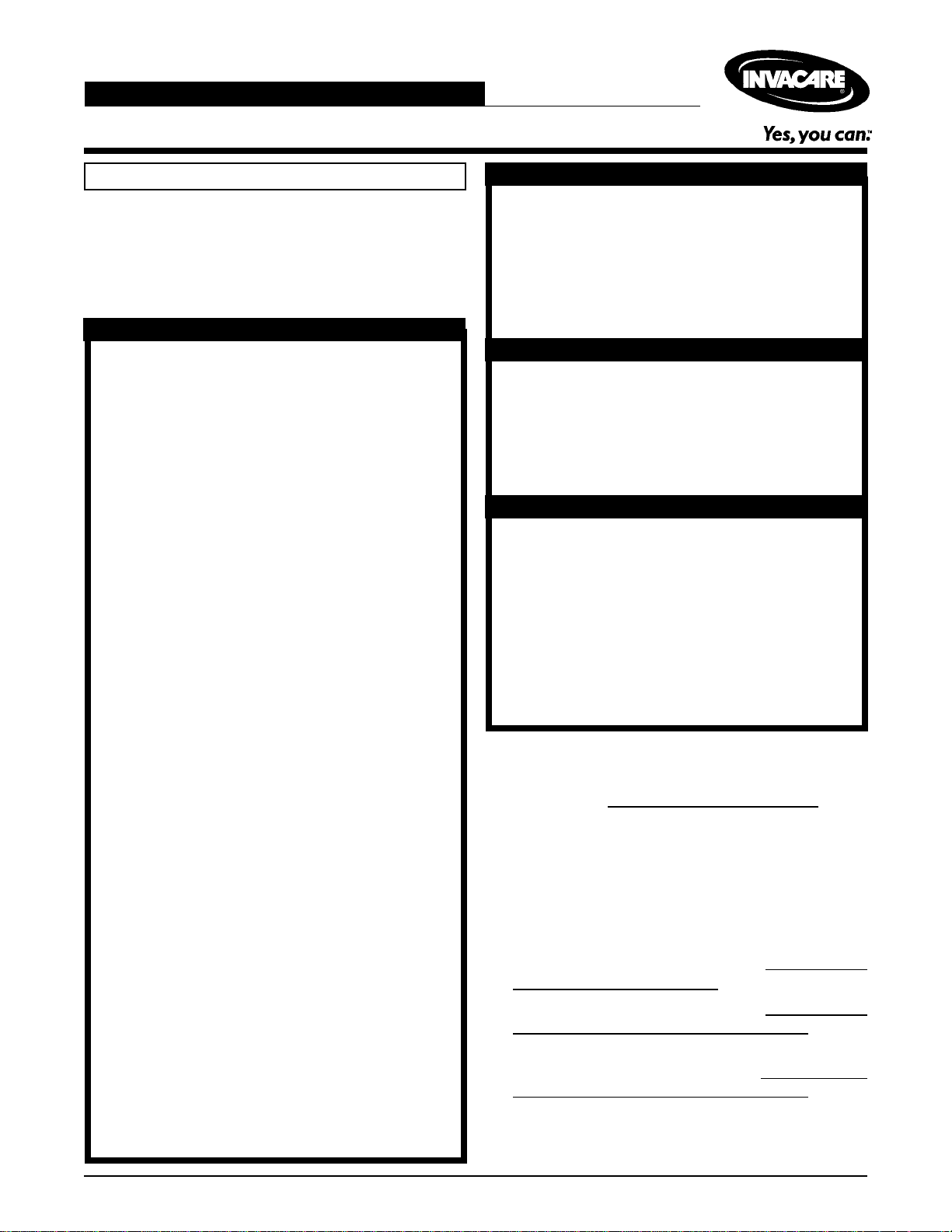
Opening the Rollator (FIGURE 1)
1. Remove the rollator from the carton.
2. Hold seat handle and push down on seat until an
audible click is heard.
3. MODELS 65800 AND 65700 ONLY: If necessary,
install the backrest. Refer to
INSTALLING THE BACKREST in this instruction sheet.
4. Install backrest pad. Refer to
INSTALLING THE BACKREST PAD in this
instruction sheet.
5. Install push handles. Refer to
ADJUSTING THE PUSH HANDLES in this
instruction sheet.
REMOVING/
REMOVING/
INSTALLING/
1
Folding the Rollator (FIGURE 1)
1. Hold seat handle and pull up.
NOTE: Model 65900 shown ONLY. Models 65800 and
65700 will open/fold the same way.
Seat
Seat Handle
FIGURE 1 - OPENING/FOLDING THE ROLLATOR
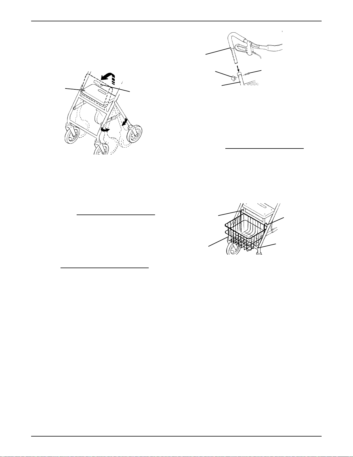
INSTALLING/ADJUSTING THE
PUSH HANDLES (FIGURE 2)
Push
Handle
Adjustment
Knob
Frame
Screw
FIGURE 2 - INSTALLING/ADJUSTING THE PUSH
HANDLES
INSTALLING THE BASKET
NOTE: Refer to INSTALLATION WARNINGS in the
SAFETY SUMMARY in this instruction sheet.
Models 65900, 65800 and 65700
(FIGURE 3)
1. Install basket between the seat support tube and the
support tube so the hooks are on the seat support
tube as shown in FIGURE 3.
NOTE: Refer to INSTALLATION WARNINGS in the
SAFETY SUMMARY in this instruction sheet.
Installing the Push Handles
1. Remove adjustment knobs and screws from both sides
of the frame by turning COUNTERCLOCKWISE.
2. Insert push handles into frames as shown in FIGURE 2.
3. Refer to
cedure of the instruction sheet.
ADJUSTING THE PUSH HANDLES in this pro-
Adjusting the Push Handles
NOTE: When making this adjustment, ensure the users
shoe height is the same as shoe style worn most frequently when using the rollator. This will provide the most
comfortable push handle position.
1. Position the push handle so that when the users arm
is down to their side, the hand grip is at wrist height.
NOTE: This will ensure the arms are at an approximate
o
- 30o bend when using the rollator.
20
2. Install screw into one (1) of the six (6) adjustment holes.
3. Secure with adjustment knob by turning CLOCKWISE.
4. Repeat STEPS 1 - 3 for the other side.
5. Securely tighten.
Hooks
Basket
NOTE: Model 65900 shown.
Seat
Support
Tube
Support
Tube
FIGURE 3 - INSTALLING THE BASKET - MODELS
65900, 65800 AND 65700
NOTE: When securely tightened, the push handles should
not move.
2
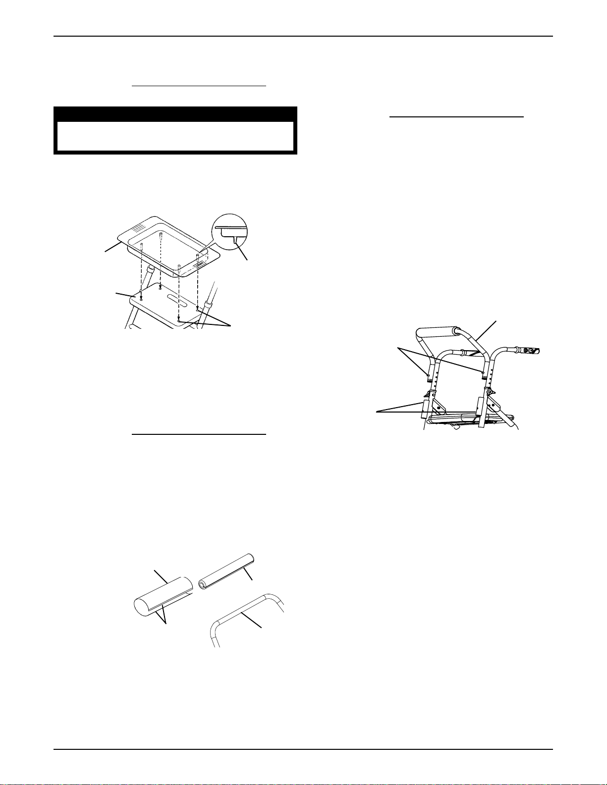
INSTALLING THE TRAY (FIGURE 4)
NOTE: Refer to INSTALLATION WARNINGS in the
SAFETY SUMMARY in this instruction sheet.
REMOVING/INSTALLING THE
BACKREST - MODELS 65800 AND
65700 ONLY (FIGURE 6)
CAUTION
DO NOT sit on the seat with the tray installed, damage to the tray may occur.
1. Align the four (4) pins on the bottom of the tray
with the four (4) holes in the seat.
2. Push down on tray to secure in place.
Tray
Pins
Seat
Holes
FIGURE 4 - INST ALLING THE TRA Y
REMOVING/INSTALLING THE BACK
SUPPORT PAD - MODELS 65900,
65800 AND 65700 (FIGURE 5)
NOTE: Refer to INSTALLATION WARNINGS in the
SAFETY SUMMARY in this instruction sheet.
Removing the Backrest
1. Depress both the two (2) snap buttons and pull UP to
remove the backrest from the backrest support tubes.
Installing the Backrest
1. Insert the backrest into the two (2) backrest support
tubes.
2. Ensure the two (2) snap buttons fully protrude through
the mounting holes of the backrest support tubes.
Backrest
Snap Buttons
Backrest Support
Tubes
NOTE: Refer to INSTALLATION WARNINGS in the
SAFETY SUMMARY in this instruction sheet.
1. Seperate the hook and latch strips and remove the
back pad cover.
2. Remove the EXISTING back pad from the backrest.
3. Slide the NEW back pad over the backrest.
4. Reinstall the back pad cover and secure with hook
and latch strips.
Back Pad Cover
Back Pad
NOTE: Model
65800 shown
Hook and Latch
Strips
Backrest
FIGURE 5 - REPLACING THE BACK SUPPORT PAD
- MODELS 65900, 65800 AND 65700 ONLY
FIGURE 6- REMOVING/INST ALLING THE
BACKREST - MODELS 65800 AND 65700 ONL Y
3

ADJUSTING THE HAND BRAKES MODELS 65900 AND 65800 ONLY
NOTE: COUNTERCLOCKWISE/CLOCKWISE directions are determined by standing behind the rollator (users
position).
NOTE: Refer to
SAFETY SUMMARY in this instruction sheet.
INSTALLATION WARNINGS in the
Cable
Caster Housing
Adjustment Nut
Caster Housing Nut
Brake Handle (FIGURE 7)
1. Loosen the brake handle adjustment nut by turning
CLOCKWISE.
2. Do one (1) of the following:
A. Loosen brake handle tension - turn brake
handle nut COUNTERCLOCKWISE.
B. Tighten brake handle tension - turn brake handle
nut CLOCKWISE.
3. Turn the brake handle adjustment nut CLOCKWISE
to secure in place.
4. Do one (1) of the following:
A. Acceptable tension - repeat STEPS 1 - 3 for
opposite side, if necessary.
B. Unacceptable tension - refer to
HOUSING in this procedure of the instruction sheet.
5. Refer to
BRAKES in this instruction sheet.
Brake Handle
Adjustment Nut
Brake Handle Nut
LOCKING/UNLOCKING/USING HAND
CASTER
FIGURE 8 - CASTER HOUSING -
MODELS 65900 ONL Y
Adjusting Cable Adjuster Unit - Wheel
Assembly - MODEL 65800 ONLY
(FIGURE 9)
NOTE: Adjusting the cable adjuster unit will increase/
decrease the cable brake pressure on the wheels.
1. Loosen the cable brake adjuster unit locknut.
2. Do one (1) of the following:
A. To increase tension, turn the cable adjuster unit
COUNTERCLOCKWISE.
B. To decrease tension, turn the cable adjuster unit
CLOCKWISE.
3. Retighten the cable adjuster unit locknut.
4. Test the brake. If the tension of the brake handle is
STILL too loose/tight, perform the following:
A. Repeat STEP 1.
B. Loosen the phillips screw on the brake clamp.
C. Pull the brake wire further through the brake clamp.
NOTE: There will be additional excess wire. It may be
necessary to fold wire up to keep wire from interfering with
brake action.
FIGURE 7 - BRAKE HANDLE
Caster Housing - MODELS 65900 ONLY
(FIGURE 8)
1. Loosen the caster housing nut.
2. Do one (1) of the following:
A. To increase tension, turn the caster housing
adjustment nut COUNTERCLOCKWISE.
B. To decrease tension, turn the caster housing
adjustment nut CLOCKWISE.
3. Retighten the caster housing nut.
4. Repeat STEPS 1 - 3 until tension is acceptable.
5. Do one of the following:
A. Refer to
BRAKES in this instruction sheet.
B. Repeat
procedure for opposite side, if necessary.
LOCKING/UNLOCKING/USING HAND
ADJUSTING THE HAND BRAKES
Brake Cable
Cable Adjuster Unit
Cable Adjuster
Unit Locknut
Brake
Phillips Screw
Brake
Clamp
FIGURE 9 - ADJUSTING CABLE ADJUSTER UNIT -
WHEEL ASSEMBL Y - MODEL 65800 ONL Y
4

LOCKING/UNLOCKING/USING
HAND BRAKES - MODELS 65900
AND 65800 ONLY
NOTE: Refer to INSTALLATION WARNINGS in the
SAFETY SUMMARY in this instruction sheet.
Locking Hand Brakes (FIGURE 10)
1. Push DOWN on the bottom portion of the brake handle
as shown in FIGURE 10 until an audible click is heard.
2. Refer to
dure of the instruction sheet.
UNLOCKING HAND BRAKES in this proce-
Brake Handle
USING BRAKES - MODEL 65700
ONLY (FIGURE 12)
NOTE: Refer to INSTALLATION WARNINGS in the
SAFETY SUMMARY in this instruction sheet.
NOTE: The brakes on Model 65700 DO NOT lock. They
will activate when seated with weight centered on the rollator
seat or when the push handles are pushed downward.
1. Push DOWN on the push handles until the crutch
tips contact the floor.
2. Do one of the following:
A. Remain stationary - continue pushing DOWN
on the push handles.
B. Continue mobility - discontinue pushing
DOWN on the push handles
FIGURE 10 - LOCKING HAND BRAKES
Unlocking Hand Brakes (FIGURE 11)
1. Pull UP on the top portion of the brake handle to release as shown in FIGURE 11.
2. Release brake handle.
Using Hand Brakes (FIGURE 14)
1. Pull UP on the top portion of the brake handles towards the push handles.
2. Do one of the following:
A. Remain stationary - hold the brake handle UP.
B. Continue mobility - release the brake handle.
Push
Handle
Push
Handles
Crutch Tip
FIGURE 12 - USING BRAKES -
MODEL 65700 ONL Y
Brake Handle
FIGURE 11- UNLOCKING/USING HAND BRAKES
5

TRANSPORT FEATURE - MODEL
65900 ONLY (FIGURE 13)
NOTE: Refer to INSTALLATION WARNINGS in the
SAFETY SUMMARY in this instruction sheet.
1. Ensure both brakes are fully engaged in the locked
position before sitting in the rollator. Refer to
LOCKING/UNLOCKING/USING HAND BRAKES in
this instruction sheet.
2. Ensure the occupants feet are firmly in place on the
footrests.
3. Unlock the brakes. Refer to
USING HAND BRAKES in this instruction sheet.
4. Grasp the transport handle to push the occupied
rollator.
Brake
LOCKING/UNLOCKING/
Transport Handle
CAUTION
DO NOT overtighten hardware, damage
to the seat may occur.
5. Position the NEW seat onto the frame as shown in
FIGURE 14.
6. Reverse STEP 3 to install NEW seat onto frame using
EXISTING screws, spacers and brackets. Tighten hardware against seat until snug.
MODELS 65900,65800 AND 65700
Seat
Spacers
Screws
Brake
Seat
Footrest
Footrests
FIGURE 13 - TRANSPORT FEA TURE -
MODEL 65900 ONL Y
REPLACING THE SEAT (FIGURE 14)
NOTE: Refer to INSTALLATION WARNINGS in the
SAFETY SUMMARY in this instruction sheet.
1. Open the rollator. Refer to
ROLLATOR in this instruction sheet.
2. Place on the floor with the underside of the seat
facing up.
3. Remove the eight (8) screws and four (4) spacers
that secure the seat to the frame.
4. Remove the EXISTING seat.
OPENING/FOLDING THE
Frame
Spacers
FIGURE 14- REPLACING THE SEA T
REPLACING WHEELS - MODELS
65900 ONLY (FIGURE 15 )
NOTE: Refer to INSTALLATION WARNINGS in the
SAFETY SUMMARY in this instruction sheet.
1. Remove the cap covers from both sides of the wheel.
2. Remove the mounting screw and locknut that secure
the EXISTING wheel to the rollator.
3. Remove EXISTING wheel.
4. Install NEW wheel and secure with NEW mounting
screw and NEW locknut.
5. Install NEW cap covers.
Cap
Cover
Mounting
Screw
Wheel
Locknut
Cap
Cover
FIGURE 15 - REPLACING WHEELS -
MODEL 65900 ONLY
6

REPLACING WHEELS - MODELS
65800 AND 65700 ONLY (FIGURE 16 )
REPLACING THE CRUTCH TIPS MODEL 65700 ONLY (FIGURE 17)
NOTE: Refer to INSTALLATION WARNINGS in the
SAFETY SUMMARY in this instruction sheet.
Replacing Front Wheels
1. Remove the mounting screw, bushing and locknut
that secure the EXISTING wheel to the rollator.
2. Remove EXISTING wheel.
3. Install NEW wheel and secure with NEW mounting
screw, bushing and NEW locknut.
Replacing Rear Wheels
1. Remove the mounting screw, bushing, two (2) coved
washers and locknut that secure the EXISTING wheel
to the rollator.
2. Remove EXISTING wheel.
3. Install NEW wheel and secure with NEW mounting screw,
bushing, two (2) coved washers and NEW locknut.
FRONT WHEELS
Locknut
NOTE: Refer to INSTALLATION WARNINGS in the
SAFETY SUMMARY in this instruction sheet.
WARNING
Model 65700 only - Check crutch tips for rips,
tears, cracks or wear. If any of these conditions
exist, replace crutch tips immediately.
1. Pull to remove the EXISTING crutch tip from the rear
frame tube.
2. Slide the NEW crutch tip onto the exposed end of the
rear frame tube.
Rear Frame Tube
Crutch Tip
FIGURE 17 - REPLACING THE CRUTCH TIPS -
MODEL 65700 ONL Y
Bushing
Mounting Screw
Bushing
Mounting Screw
Wheel
REAR WHEELS
Locknut
Coved Washers
Wheel
FIGURE 16 - REPLACING WHEELS - MODELS
65800 AND 65700 ONL Y
7

LIMITED WARRANTY
NOTE: THE WARRANTY BELOW HAS BEEN DRAFTED TO COMPLY WITH FEDERAL LAW APPLICABLE TO PRODUCTS MANUFACTURED AFTER JULY 4, 1975.
This warranty is extended only to the original purchaser/user of our product.
This warranty gives you specific legal rights and you may also have other legal rights
which vary from state to state.
Invacare warrants the frame to be free from defects in materials and workmanship for
the lifetime of the product, six (6) years on the hand brakes and one (1) year for all other
remaining components, excluding tires/wheels for the original purchaser/user. If within
such warranty period any such product shall be proven to be defective, such product
shall be repaired or replaced, at Invacare’s option. This warranty does not include any
labor or shipping charges incurred in replacement part installation or repair of any such
product. Invacare’s sole obligation and your exclusive remedy under this warranty
shall be limited to such repair and/or replacement.
For warranty service, please contact the dealer from whom you purchased your
Invacare product. In the event you do not receive satisfactory warranty service,
please write directly to Invacare at the address on the back cover, provide dealers
name, address, date of purchase, indicate nature of the defect and, if the product is
serialized, indicate the serial number. Do not return products to our factory without our
prior consent.
LIMITATIONS AND EXCLUSIONS: THE FOREGOING WARRANTY SHALL NOT APPLY TO SERIAL
NUMBERED PRODUCTS IF THE SERIAL NUMBER HAS BEEN REMOVED OR DEFACED; PRODUCTS SUBJECTED TO NEGLIGENCE, ACCIDENT, IMPROPER OPERATION, IMPROPER MAINTENANCE OR STORAGE, COMMERCIAL OR INSTITUTIONAL USE; PRODUCTS MODIFIED WITHOUT INVACARE’S EXPRESS WRITTEN CONSENT INCLUDING, BUT NOT LIMITED TO, MODIFICATION THROUGH THE USE OF UNAUTHORIZED PARTS OR ATTACHMENTS; PRODUCTS DAMAGED BY REASON OF REPAIRS MADE TO ANY COMPONENT WITHOUT THE SPECIFIC CONSENT OF INVACARE; OR TO A PRODUCT DAMAGED BY CIRCUMSTANCES BEYOND
INVACARE’S CONTROL. SUCH EVALUATION WILL BE SOLELY DETERMINED BY INVACARE.
THE WARRANTY SHALL NOT APPLY TO PROBLEMS ARISING FROM NORMAL WEAR OR FAILURE TO ADHERE TO THESE INSTRUCTIONS.
THE FOREGOING WARRANTY IS EXCLUSIVE AND IN LIEU OF ALL OTHER EXPRESS WARRANTIES. IMPLIED WARRANTIES, IF ANY, INCLUDING THE IMPLIED WARRANTIES OF MERCHANTABILITY AND FITNESS FOR A PARTICULAR PURPOSE, SHALL NOT EXTEND BEYOND THE DURATION OF THE EXPRESS WARRANTY PROVIDED HEREIN AND THE REMEDY FOR VIOLATIONS OF
ANY IMPLIED WARRANTY SHALL BE LIMITED TO REPAIR OR REPLACEMENT OF THE DEFECTIVE PRODUCT PURSUANT TO THE TERMS CONTAINED HEREIN. INVACARE SHALL NOT BE
LIABLE FOR ANY CONSEQUENTIAL OR INCIDENTAL DAMAGES WHATSOEVER. SOME STATES
DO NOT ALLOW THE EXCLUSION OR LIMITATION OF INCIDENTAL OR CONSEQUENTIAL
DAMAGE, OR LIMITATION ON HOW LONG AN IMPLIED WARRANTY LASTS, SO THE ABOVE
EXCLUSIONS AND LIMITATIONS MAY NOT APPLY TO YOU.
Invacare Corporation www.invacare.com
USA Canada
One Invacare Way 570 Matheson Blvd E Unit 8 Invacare is a registered trademark of
Elyria, Ohio USA Mississauga Ontario Invacare Corporation.
44036-2125 L4Z 4G4 Canada Yes, you can. is a trademark of Invacare
800-333-6900 800-668-5324 Corporation.
© 2001 Invacare Corporation
Part No. 1100867 Rev B 01/02
 Loading...