


Owner's Operator And Maintenance Manual
Tilt
Recline
Tilt/Recline
Seating Systems
DEALER: THIS MANUAL MUST BE GIVEN TO THE USER
OF THE WHEELCHAIR.
USER: BEFORE USING THIS WHEELCHAIR, READ THIS
MANUAL AND SAVE FOR FUTURE REFERENCE.
WARNING/SPECIAL NOTES
WARNING
DO NOT OPERATE THIS EQUIPMENT WITHOUT FIRST READING AND
UNDERSTANDING THIS MANUAL AND THE MANUAL PROVIDED WITH THE
W
A
R
N
N
G
S
P
E
C
A
L
N
O
T
E
S
WHEELCHAIR. IF YOU ARE UNABLE TO UNDERSTAND THE WARNINGS
AND INSTRUCTIONS, CONTACT A TRAINED INVACARE DEALER OR
INVACARE TECHNICAL SUPPORT BEFORE ATTEMPTING TO USE THIS
I
EQUIPMENT - OTHERWISE INJURY OR DAMAGE MAY RESULT.
THIS SEATING SYSTEM HAS BEEN CUSTOM DESIGNED AND WILL BE
ASSEMBLED TO THE WHEELCHAIR BASE BEFORE DELIVERY TO THE USER. THE
INFORMATION CONTAINED IN THIS MANUAL IS FOR MAINTAINING AND
ADJUSTING THE SEATING SYSTEM. PROCEDURES OTHER THAN THOSE
DESCRIBED IN THIS MANUAL MUST BE PERFORMED BY A QUALIFIED
TECHNICIAN.
SPECIAL NOTES
WARNING/CAUTION notices as used in this manual apply to hazards or unsafe practices
which may result in personal injury or property damage.
NOTICE
THE INFORMATION CONTAINED IN THIS DOCUMENT IS SUBJECT TO CHANGE WITHOUT
NOTICE.
SEATING SYSTEM/WHEELCHAIR USER
As a manufacturer of wheelchairs and seating systems, Invacare endeavors to supply
a wide variety of wheelchairs and seating systems to meet many needs of the user.
However, final selection of the type of wheelchair and seating system to be used by an
I
individual rests solely with the user and his/her healthcare professional capable of
making such a selection.
WHEELCHAIR TIE-DOWN RESTRAINTS AND SEAT POSITIONING STRAPS
Invacare recommends that wheelchair and seating system users NOT be transported in
vehicles of any kind while in wheelchairs. As of this date, the Department of Transportation has not approved any tie-down systems for transportation of a user while in a
wheelchair, in a moving vehicle of any type.
It is Invacare’s position that users of wheelchairs and seating systems should be transferred into appropriate seating in vehicles for transportation and use be made of the
restraints made available by the auto industry. Invacare cannot and does not recommend any wheelchair transportation systems.
SAVE THESE INSTRUCTIONS.
2

TABLE OF CONTENTS
TABLE OF CONTENTS
SPECIAL NOTES ................................................................................................................................ 2
SPECIFICATIONS ............................................................................................................................... 4
PROCEDURE 1 - GENERAL GUIDELINES ...........................................................................5
REPAIR OR SERVICE INFORMATION ............................................................................................... 5
OPERATING INFORMATION .............................................................................................................. 5
SAFETY/HANDLING OF SEATING SYSTEMS/WHEELCHAIRS ......................................................... 9
PROCEDURE 2 - SAFETY INSPECTION/TROUBLESHOOTING ........................................ 11
SAFETY INSPECTION AND MAINTENANCE CHECKLIST ............................................................... 11
TROUBLESHOOTING ..................................................................................................................... 11
PROCEDURE 3 - TILT ONLY ...............................................................................................12
OPERATING TILT ONLY SYSTEMS ................................................................................................. 12
T
A
B
L
E
O
F
C
O
N
T
E
N
T
S
PROCEDURE 4 - RECLINE ONLY ....................................................................................... 14
OPERATING RECLINE SYSTEMS ONLY ......................................................................................... 14
PROCEDURE 5 - TILT/RECLINE ......................................................................................... 16
OPERATING TILT/RECLINE SYSTEMS ........................................................................................... 16
PROCEDURE 6 - VENTILATOR TRAY ................................................................................ 18
USING THE OPTIONAL VENT TRAY ................................................................................................ 18
PROCEDURE 7 - SHEAR REDUCTION ..............................................................................19
OPTIONAL VERNIER SHEAR .......................................................................................................... 19
PROCEDURE 8 - RIGGINGS ............................................................................................... 20
MECHANICAL ELEVATING/GENIUS LEGRESTS ............................................................................. 20
INSTALLING/REMOVING THE POWERED LEGS .................................................................................. 22
ADJUSTING THE POWER LEGRESTS ............................................................................................. 23
PROCEDURE 9 - ARMRESTS ............................................................................................. 27
RECLINING ARMRESTS .................................................................................................................. 27
PROCEDURE 10 - HEADREST ........................................................................................... 28
ADJUSTING HEADREST HEIGHT/DEPTH/DIRECTION ................................................................... 28
REPLACING HEADREST ................................................................................................................ 28
PROCEDURE 11 - EXTENDED ACTIVE ANTI-TIPPERS ..................................................... 29
USING THE EXTENDED ACTIVE ANTI-TIPPERS ............................................................................. 29
LIMITED WARRANTY ...................................................................................................................... 30
3

SPECIFICATIONS
SPECIFICATIONS
S
NOTE: All specifications apply to Tilt only, Recline only and Tilt/Recline systems except where specified.
P
All specifications are approximate.
E
C
NOTE: The procedures in this manual refer to RWD and FWD models except where specified.
I
NOTE: Refer to the wheelchair owner's manual for complete specifications on base and operation.
F
Seat Width Range:
I
C
Seat Depth Range:
A
Back Height Range:
T
I
Recline Only and Tilt/Recline:
Tilt Only:
O
N
Back Angle Range
S
Tilt Only Systems:
16 to 22-inches - In 1-inch increments
16 to 22-inches - In 1-inch increments
20 to 26-inches - In 1-inch increments
20 to 25-inches - In 1-inch increments
o
to 115o - in 5o increments
90
Tilt Range
Tilt Only Systems:
Tilt/Recline Systems:
Recline Range
Recline Only and Tilt/Recline Systems:
Seat-to-Floor:
*Overall Width:
*Overall Height:
*Overall Length:
Weight of Seating System:
Armrests
Tilt Only:
**Recline Only and Tilt/Recline Systems:
Legrests:
o
Seat Angle - 0o to 45
0
5o Seat Angle - 5o to 50
0o Seat Angle - 0o to 45
5o Seat Angle - 5o to 50
0o Seat Angle - 90o to 175
5o Seat Angle - 95o to 175
o
o
o
o
o
o
0o Seat Angle - 18-1/4-inches
5o Seat Angle - 19-3/4-inches
25 to 27-inches
53-inches
48-inches - in upright position
105 lbs.
Flip Back, Adjustable Height (9 to 13-inches) - Desk or Full Length
Adjustable Height (11 to 16-inches) - Desk or Full Length
Mechanical Elevating/Genius Legrests
Power Legrests
Headrests:
Curved, Contoured, Small or Large
*NOTE: 18 x 18 Tilt/Recline System on Storm Base (short frame) with AT5544 front riggings in minimum
position, seat angle of 5o, back height of 24-inches and headrest.
4
GENERAL GUIDELINES PROCEDURE 1
This Procedure Includes the Following:
Repair or Service Information
Operating Information
Safety/Handling of Wheelchairs
REPAIR OR SERVICE INFORMATION
Setup of the Electronic Control Unit is to be performed ONLY by authorized Invacare
dealers. The final tuning adjustments of the controller may affect other activities of the
wheelchair. Damage to the equipment could occur under these circumstances. If any
individual other than an authorized Invacare dealer performs any work on these units,
the warranty is void.
OPERATING INFORMATION
WARNING
Performance adjustments should only be made by professionals of the health
care field or persons fully conversant with this process and the driver's capabilities. Incorrect settings could cause injury to the driver, bystanders, damage to
the chair and to surrounding property.
After the wheelchair has been setup, check to make sure that the wheelchair
performs to the specifications entered during the setup procedure. If the wheelchair does NOT perform to specifications, turn the wheelchair OFF immediately
and reenter setup specifications. Repeat this procedure until the wheelchair
performs to specifications.
To determine and establish your particular safety limits, practice bending, reaching
and transferring activities in several combinations in the presence of a qualified
health professional BEFORE attempting active use of the seating system/wheelchair.
DO NOT attempt to reach objects if you have to move forward in the seat.
DO NOT attempt to reach objects if you have to pick them up from the floor by
reaching down between your knees.
DO NOT lean over the top of the back upholstery to reach objects from behind
as this may cause the seating system/wheelchair to tip over.
DO NOT shift your weight or sitting position toward the direction you are reach-
ing as the seating system/wheelchair may tip over.
DO NOT operate the seating system while on an incline.
DO NOT operate the seating system while the wheelchair is moving.
TILT ONLY SYSTEMS - NEVER operate the wheelchair while in any tilted position
over 20
the wheelchair from operating in a tilt position 20
POSITION, DO NOT operate the wheelchair. Have the wheelchair serviced by a
dealer or qualified technician.
RECLINE ONLY SYSTEMS - NEVER operate the wheelchair while in any recline/
back angle combination over 20
drive lock-out does not stop the wheelchair from operating in a recline/back
angle combination 20
wheelchair. Have the wheelchair serviced by a dealer or qualified technician.
TILT/RECLINE SYSTEMS - NEVER operate the wheelchair while in any tilt/recline/
back angle combination over 20
drive lock-out does not stop the wheelchair from operating in a tilt/recline/
back angle combination 20
ate the wheelchair. Have the wheelchair serviced by a dealer or qualified technician.
o
RELATIVE TO THE VERTICAL POSITION. If the drive lock-out does not stop
o
RELATIVE TO THE VERTICAL POSITION. If the
o
RELATIVE TO THE VERTICAL POSITION, DO NOT operate the
o
RELATIVE TO THE VERTICAL POSITION. If the
o
RELATIVE TO THE VERTICAL POSITION, DO NOT oper-
o
RELATIVE TO THE VERTICAL
G
E
N
E
R
A
L
G
U
I
D
E
L
I
N
E
S
5

G
N
R
G
U
D
N
GENERAL GUIDELINESPROCEDURE 1
WARNING
Use only TSS, SAC, TRSS and TRCM actuator controls to activate the tilt/recline functions. DO
E
E
A
L
I
E
L
I
E
S
NOT USE any other actuator controls. Such devices may result in excess heating and cause
damage to the actuator and associated wiring and could cause a fire, death, physical
injury or property damage. If such devices are used, Invacare shall not be liable and the
warranty is void.
VENT TRAY - Chairs equipped with vent tray option: Reduced tilt/recline limits apply. See
MKIV TRCM operating instructions, part number 1043576.
DO NOT tip the seating system/wheelchair without assistance.
DO NOT use an escalator to move a seating system/wheelchair between floors. Serious
bodily injury may occur.
Before attempting to transfer in or out of the seating system/wheelchair, every
precaution should be taken to reduce the gap distance. Turn both casters toward the object you are transferring onto. Also be certain the power is OFF and
motor locks are engaged to prevent the wheels from moving.
DO NOT engage or disengage the motor locks until the power is in the OFF
position.
DO NOT operate on roads, streets or highways.
o
DO NOT climb, go up or down ramps or traverse slopes greater than 9
.
DO NOT attempt to move up or down an incline with a water, ice or oil film.
DO NOT attempt to drive over curbs or obstacles. Doing so may cause your
seating system/ Wheelchair to turn over and cause bodily harm or damage to
the seating system/wheelchair.
DO NOT use parts, accessories, or adapters other than those authorized by
Invacare.
DO NOT leave the power ON when entering or exiting your seating system/
wheelchair.
DO NOT attempt to lift the seating system/wheelchair by lifting on any removable (detachable) parts. Lifting by means of any removable (detachable) parts
of a seating system/wheelchair may result in injury to the user or damage to the
seating system/wheelchair.
DO NOT stand on the frame of the seating system/wheelchair.
Anti-tippers MUST BE attached at all times.
DO NOT use the footplates as a platform. When getting in or out of the seating
system/wheelchair, make sure that the footplates are in the upward position or
swing footrests towards the outside of the seating system/wheelchair.
ALWAYS wear your seat positioning strap.
Individual user weight may impact the rate of travel for each legrest assembly.
If simultaneous operation is desired, select a speed which allows for the most
uniform travel. To prevent personal injury, always verify proper positioning of legs and feet
prior to use.
WEIGHT TRAINING
Invacare DOES NOT recommend the use of its wheelchairs and seating systems as a weight
training apparatus. Invacare wheelchairs and seating systems have NOT been designed
or tested as a seat for any kind of weight training. If occupant uses said seating system/
wheelchair as a weight training apparatus, INVACARE SHALL NOT BE LIABLE FOR BODILY
INJURY AND THE WARRANTY IS VOID.
6

GENERAL GUIDELINES PROCEDURE 1
CAUTION
WEIGHT LIMITATION
S
A
F
E
T
Standard Tilt only, Recline only and Tilt/Recline systems have a weight limitation of 250 lbs.
Tilt only, Recline only and Tilt/Recline systems with the heavy duty option have a weight
limitation of 350lbs.
Never allow items to become trapped between the legrest assemblies, otherwise damage
to the power legrest may occur.
Y
S
U
M
M
A
R
Y
CAUTION: IT IS VERY IMPORTANT THAT YOU READ THIS INFORMATION REGARDING THE POSSIBLE EFFECTS OF ELECTROMAGNETIC INTERFERENCE ON YOUR POWERED WHEELCHAIR.
Electromagnetic Interference (EMI) From Radio Wave sources
Powered wheelchairs and motorized scooters (in this text, both will be referred to as pow-
ered wheelchairs) may be susceptible to electromagnetic interference (EMI), which is
interfering electromagnetic energy (EM) emitted from sources such as radio stations, TV
stations, amateur radio (HAM) transmitters, two way radios, and cellular phones. The interference (from radio wave sources) can cause the powered wheelchair to release its brakes,
move by itself, or move in unintended directions. It can also permanently damage the
powered wheelchair's control system. The intensity of the interfering EM energy can be
measured in volts per meter (V/m). Each powered wheelchair can resist EMI up
to a certain intensity. This is called its "immunity level." The higher the immunity
level, the greater the protection. At this time, current technology is capable of
achieving at least a 20 V/m immunity level, which would provide useful protec-
tion from the more common sources of radiated EMI.
W ARNING
G
E
N
E
R
A
L
G
U
I
D
E
L
I
N
E
S
There are a number of sources of relatively intense electromagnetic fields in the
everyday environment. Some of these sources are obvious and easy to avoid.
Others are not apparent and exposure is unavoidable. However, we believe
that by following the warnings listed, your risk to EMI will be minimized.
The sources of radiated EMI can be broadly classified into three types:
1) Hand-held Portable transceivers (transmitters-receivers with the antenna
mounted directly on the transmitting unit. Examples include: citizens band
(CB) radios, "walkie talkie," security, fire, And police transceivers, cellular
telephones, and other personal communication devices. **NOTE: Some cellular telephones and similar devices transmit signals while they are ON,
even when not being used;
2) Medium-range mobile transceivers, such as those used in police cars, fire
trucks, ambulances, and taxis. These usually have the antenna mounted on
the outside of the vehicle; and
3) Long-range transmitters and transceivers, such as commercial broadcast
transmitters (radio and TV broadcast antenna towers) and amateur (HAM) radios.
7

G
N
R
G
U
D
N
GENERAL GUIDELINESPROCEDURE 1
W ARNING
NOTE: Other types of hand-held devices, such as cordless phones, laptop computers, AM
E
E
A
L
I
E
L
I
E
S
FM radios, TV sets, CD players, cassette players, and small appliances, such as electric
shavers and hair dryers, so far as we know, are not likely to cause EMI problems to your
powered wheelchair.
Powered Wheelchair Electromagnetic Interference (EMI)
Because EM energy rapidly becomes more intense as one moves closer to the transmitting
antenna (source), the EM fields from hand-held radio wave sources (transceivers) are of
special concern. It is possible to unintentionally bring high levels of EM energy very close
to the powered wheelchair's control system while using these devices. This can affect powered wheelchair movement and braking. Therefore, the warnings listed are recommended
to prevent possible interference with the control system of the powered wheelchair.
Electromagnetic interference (EMI) from sources such as radio and TV stations, amateur
radio (HAM) transmitters, two-way radios, and cellular phones can affect powered wheelchairs and motorized scooters. Following the warnings listed below should reduce the
chance of unintended brake release or powered wheelchair movement which could result in serious injury.
1) Do not operate hand-held transceivers (transmitters receivers), such as citizens band (CB) radios, or turn ON personal communication devices, such
as cellular phones, while the powered wheelchair is turned ON;
2) Be aware of nearby transmitters, such as radio or TV stations, and try to
avoid coming close to them;
3) If unintended movement or brake release occurs, turn the powered wheelchair OFF as soon as it is safe;
4) Be aware that adding accessories or components, or modifying the powered wheelchair, may make it more susceptible to EMI (Note: There is no
easy way to evaluate their effect on the overall immunity of the powered
wheelchair); and
5) Report all incidents of unintended movement or brake release to the powered wheelchair manufacturer, and note whether there is a source of EMI
nearby.
Important Information
1) 20 volts per meter (V/m) is a generally achievable and useful immunity
level against EMI (as of May 1994) (the higher the level, the greater the
protection);
2) The immunity level of this product is not known.
Modification of any kind to the electronics of this wheelchair as manufactured
by Invacare may adversely affect the RFI immunity levels.
8
GENERAL GUIDELINESPROCEDURE 1
SAFETY/HANDLING OF SEATING
SYSTEMS/WHEELCHAIRS
Safety and Handling of the wheelchair requires the close
attention of the seating system/wheelchair user as well
as the assistant. This manual, as well as the owners
manual provided with the wheelchair, points out the most
common procedures and techniques involved in the safe
operation and maintenance of the seating system/wheelchair. It is important to practice and master these safe
techniques until you are comfortable in maneuvering
around the frequently encountered architectural barriers.
Use this information only as a basic guide. The techniques that are discussed on the following pages have
been used successfully by many.
Individual seating system/wheelchair users often develop
skills to deal with daily living activities that may differ from
those described in this manual. Invacare recognizes and
encourages each individual to try what works best for him/
her in overcoming architectural obstacles that they may
encounter, however, ALL WARNINGS and CAUTIONS
given in this manual MUST be followed. Techniques in
this manual are a starting point for new seating system/
wheelchair users and assistants with safety as the most
important consideration for all.
Also, be aware of any detachable parts. These must
NEVER be used for hand-hold or lifting supports, as they
may be inadvertently released, resulting in possible injury
to the user and/or assistant(s).
When learning a new assistance technique, have an experienced assistant help you before attempting it alone.
Percentage of Weight Distribution
WARNING
DO NOT attempt to reach objects if you
have to move forward in the seat or pick
them up from the floor by reaching down
between your knees.
Many activities require the wheelchair owner to reach, bend
and transfer in and out of the wheelchair. These movements will cause a change to normal balance, center of
gravity, and weight distribution of the wheelchair. To determine and establish your particular safety limits, practice
bending, reaching and transferring activities in several combinations in the presence of a qualified health professional
BEFORE attempting active use of the wheelchair.
Proper positioning is essential for your safety. When reaching, leaning, bending or bending forward, it is important to
use the front casters as a tool to maintain stability and balance.
G
E
N
E
R
A
L
G
U
I
D
E
L
I
N
E
S
Stability and Balance
WARNING
Always wear your seat positioning strap.
To assure stability and proper operation of your seating
system/wheelchair, you must at all times maintain proper
balance. Your seating system/wheelchair has been designed to remain upright and stable during normal daily
activities as long as you do not move beyond the center of
gravity.
DO NOT lean forward out of the seating system/wheelchair any further than the length of the armrests. Make
sure the casters are pointing in the forward position whenever you lean forward. This can be achieved by advancing the wheelchair and then reversing it in a straight line.
Coping With Everyday Obstacles
Coping with the irritation of everyday obstacles can be
alleviated somewhat by learning how to manage your
wheelchair. Keep in mind your center of gravity to maintain stability and balance.
A Note to Wheelchair Assistants
When assistance to the seating system/wheelchair user
is required, remember to use good body mechanics. Keep
your back straight and bend your knees.
9
GENERAL GUIDELINESPROCEDURE 1
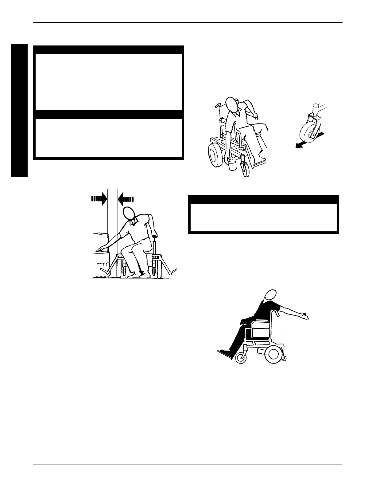
Transferring To/From Other Seats
G
E
N
E
R
A
L
G
U
I
D
E
L
I
N
E
S
BEFORE attempting to transfer in or out of
the wheelchair, every precaution should
be taken to reduce the gap distance. Turn
both casters toward the object you are
transferring onto. Also be certain to engage motor locks to help prevent the
wheels from moving.
When transferring, position yourself as far
back as possible in the seat. This will prevent broken screws, damaged upholstery
and the possibility of the wheelchair tipping forward.
NOTE: This activity may be performed independently provided you have adequate mobility and upper body
strength.
MINIMIZE
GAP
DIST ANCE
WARNING
CAUTION
Reaching, Leaning, Bending and Bending Forward
Position the front casters so that they are extended as far
forward as possible and engage wheel locks. DO NOT
ATTEMPT TO REACH OBJECTS IF YOU HAVE TO
PICK THEM UP FROM THE FLOOR BY REACHING
DOWN BETWEEN YOUR KNEES.
Reaching, Bending - Backwards
WARNING
DO NOT lean over the top of the back
upholstery. This will change your center
of gravity and may cause you to tip over.
Position the wheelchair as close as possible along
side the seat to which you are transferring, with the
casters aligned parallel with the object. Engage
motor locks. Shift body weight into seat with transfer.
During independent transfer, little or no seat platform
will be beneath you. Use a transfer board if at all possible.
Position wheelchair as close as possible to the desired object. Point front casters forward to create the
longest possible wheelbase. Reach back only as far
as your arm will extend without changing your sitting
position.
10

SAFETY INSPECTION/TROUBLESHOOTING
PROCEDURE 2
This Procedure Includes the Following:
Safety Inspection and Maintenance Checklist
Troubleshooting
SAFETY INSPECTION AND MAINTENANCE CHECKLIST
NOTE: Every six (6) months, take your seating system/wheelchair to a qualified dealer for a thorough inspection and servicing.
Regular cleaning will reveal loose or worn parts and enhance the smooth operation of your seating system/wheelchair. To operate
properly and safely, your seating system/wheelchair must be cared for just like any other vehicle. Routine maintenance will extend
the life and efficiency of your seating system/wheelchair.
Initial adjustments should be made to suit your personal body structure and preference. Thereafter follow these maintenance procedures.
NOTE: Refer to the wheelchair owners manual for a complete safety inspection checklist on the base.
ITEM INITIALLY INSPECT/ INSPECT/ INSPECT/
ELECTRICAL CONNECTIONS
l Make sure all electrical connections are secure. X X
l Check limit switch position. X X
DRIVE LOCK-OUT
l Make sure Drive lock-out operates properly. X X
TILT MECHANISM
l Make sure tilt operates smoothly and properly. X X
RECLINE MECHANISM
l Make sure recline operates smoothly and properly. X X
CLOTHING GUARDS
l Ensure all fasteners are secure. X X
ARMS
l Secure but easy to release; adjustment levers engage properly. X X
l Adjustable height arms operate and lock securely. X X
ARMRESTS
l Inspect for rips in upholstery. X X
l Armrest pad sits flush against arm tube. X X
SEAT AND BACK CUSHIONS
l Inspect for rips. X X
CLEANING
l Clean cushions and armrests. X X
ADJUST ADJUST ADJUST
WEEKLY MONTHLY PERIODICALLY
TROUBLESHOOTING
NOTE: Refer to wheelchair owner's manual for complete mechanical and electrical troubleshooting guides on base.
NOTE: Refer to the individual CONTROLLER MANUAL supplied with each wheelchair for additional troubleshooting information
and explanation of error codes.
S
A
F
E
T
Y
I
N
S
P
E
C
T
I
O
N
T
R
O
U
B
L
E
S
H
O
O
T
I
N
G
SYMPTOM PROBABLE SOLUTIONS
CAUSE
Wheelchair Power ON but does not
drive.
Seating system not functioning.
System tilted beyond drive lock-out
angle.
Low Batteries.
Faulty electrical connection.
Blown Fuse.
Tilt to neutral (upright) position. Contact Dealer/
Invacare for Service.
Charge batteries.
Check all connections. Contact Dealer/Invacare for Service.
Replace fuse. Contact Dealer/Invacare for Service.
11

TILT ONLYPROCEDURE 3
This Procedure Includes the Following:
Operating Tilt Only Systems
OPERATING TILT ONLY SYSTEMS
T
(FIGURE 1)
I
L
T
O
N
L
Y
NEVER operate the wheelchair while in any
tilt/back angle combination over 20o RELATIVE TO THE VERTICAL POSITION. If the drive
lock-out does not stop the wheelchair from
operating in a tilt/back angle combination
20o RELATIVE TO THE VERTICAL POSITION, DO
NOT operate the wheelchair. Have the
wheelchair serviced by a dealer or qualified technician.
Use only TSS, SAC, TRSS and TRCM actuator
controls to activate the tilt/recline functions.
DO NOT USE any other actuator controls.
Such devices may result in excess heating
and cause damage to the actuator and associated wiring and could cause a fire,
death, physical injury or property damage.
If such devices are used, Invacare shall not
be liable and the warranty is void.
A Note About Drive Lock-Out
WARNING
2. Pull single function toggle switch back towards rear
of the wheelchair until the desired angle is achieved.
DECREASING TILT ANGLE.
1. Push the single function toggle switch forward towards
the front of the wheelchair until the desired angle is
achieved.
Optional Four-Way Toggle Switch
INCREASING/DECREASING TILT ANGLE.
1. Make sure the wheelchair is on a level surface.
2. Push four-way toggle switch forward towards the front
of the wheelchair until the desired tilt angle is achieved.
NOTE: If the wheelchair is equipped with switch options, scan to the correct ECU or Auxiliary Mode
and activate the control device in the corresponding forward direction to operate the tilt function. Refer
to the MKIV owner's manual, part number 1043576
for complete switch option operating instructions.
3. Release four-way toggle switch to neutral position.
NOTE: The four-way toggle switch will alternate
functions (increase tilt angle, decrease tilt angle)
after it has been released to the neutral position for
a minimum of one (1) second.
NOTE: Refer to the MKIV owner's manual, part number 1043576 for complete four-way toggle switch operating instructions.
Drive lock-out is a feature designed to prevent the wheelchair from being driven while in any recline/back angle combination over 20
TION. When the drive lock-out feature has been activated,
the LED on the single function toggle switch will light.
NOTE: The tilt angle range is from 0
to- floor angle and 5
o
RELATIVE TO THE VERTICAL POSI-
o
o
to 50o with a 5o seat-to-floor angle.
to 45o with a 0o seat-
Single Function Toggle Switch
INCREASING TILT ANGLE.
1. Make sure the wheelchair is on a level surface.
12

TILT ONLY PROCEDURE 3
Single Function
Toggle Switch
FULL UPRIGHT
POSITION
LED
Optional Four-Way
Toggle Switch (Shown
in Neutral Position)
FULL TILT POSITION
LED
T
I
L
T
O
N
L
Y
NOTE: Illustration depicts RWD models. The tilt function operates in the same manner for FWD models.
FIGURE 1 - OPERATING TILT ONLY SYSTEMS
13

RECLINE ONLYPROCEDURE 4
This Procedure Includes the Following:
Operating Recline Only Systems
R
OPERATING RECLINE ONLY
E
SYSTEMS (FIGURE 1)
C
L
I
N
E
O
N
L
Y
NEVER operate the wheelchair while in
any recline/back angle combination over
o
20
RELATIVE TO THE VERTICAL POSITION.
If the drive lock-out does not stop the
wheelchair from operating in a recline/
back angle combination 20
THE VERTICAL POSITION, DO NOT operate
the wheelchair. Have the wheelchair serviced by a dealer or qualified technician.
Reduced Recline limits apply with optional
vent tray. See MKIV TRCM operating instructions, part number 1043576.
Use only TSS, SAC, TRSS and TRCM actuator
controls to activate the tilt/recline functions.
DO NOT USE any other actuator controls.
Such devices may result in excess heating
and cause damage to the actuator and associated wiring and could cause a fire,
death, physical injury or property damage.
If such devices are used, Invacare shall not
be liable and the warranty is void.
WARNING
o
RELATIVE TO
Increasing/Decreasing Recline Angle
NOTE: The recline angle range is from 95o to 175
with a 5o seat-to-floor angle. The recline angle range
is from 90o to 175o with a 0o seat-to-floor angle.
1. Make sure the wheelchair is on a level surface.
2. Pull the four-way toggle switch back towards the rear
of the wheelchair until the desired recline angle is
achieved.
NOTE: If the wheelchair is equipped with switch options, scan to the correct ECU or Auxiliary Mode,
then activate the control device in the corresponding reverse direction to operate the recline function. Refer to the MKIV owner's manual, part number 1043576 for complete switch option operating
instructions.
3. Release the four-way toggle switch to the neutral position.
NOTE: The four-way toggle switch will alternate
functions (increase recline angle, decrease recline
angle) after it has been released to the neutral position for a minimum of one (1) second.
NOTE: Refer to the MKIV owner's manual, part number 1043576 for complete four-way toggle switch operating instructions.
o
A Note About Drive Lock-Out
Drive lock-out is a feature designed to prevent the wheelchair from being driven while in any recline/back angle
combination over 20o RELATIVE TO THE VERTICAL POSITION. When the drive lock-out feature has been activated, the LED on the four-way toggle switch will light.
14

RECLINE ONLY PROCEDURE 4
Optional Four-Way
Toggle Switch (Shown
in Neutral Position)
FULL UPRIGHT POSITION FULL RECLINE POSITION
LED
R
E
C
L
I
N
E
O
N
L
Y
NOTE: Illustration depicts RWD models. The recline function operates in the same manner for FWD
models.
FIGURE 1 - OPERATING RECLINE ONLY SYSTEMS
15

This Procedure Includes the Following:
Operating Tilt /Recline Systems
T
OPERATING TILT/RECLINE
I
SYSTEMS (FIGURE 1)
L
R
C
N
T
E
L
E
/
I
NEVER operate the wheelchair while in any
tilt/recline/back angle combination over
20o RELATIVE TO THE VERTICAL POSITION. If
the drive lock-out does not stop the wheelchair from operating in a tilt/recline/back
angle combination 20o RELATIVE TO THE
VERTICAL POSITION, DO NOT operate the
wheelchair. Have the wheelchair serviced
by a dealer or qualified technician.
Reduced Tilt and Recline limits apply with
optional vent tray. See MKIV TRCM operating instructions, part number 1043576.
Use only TSS, SAC, TRSS and TRCM actuator
controls to activate the tilt/recline functions.
DO NOT USE any other actuator controls.
Such devices may result in excess heating
and cause damage to the actuator and associated wiring and could cause a fire,
death, physical injury or property damage.
If such devices are used, Invacare shall not
be liable and the warranty is void.
WARNING
A Note About Drive Lock-Out
Drive lock-out is a feature designed to prevent the wheelchair from being driven while in any tilt/recline/back angle
combination over 20
POSITION. When the drive lock-out feature has been
activated, the LED on the four-way toggle switch will light.
o
RELATIVE TO THE VERTICAL
TILT/RECLINEPROCEDURE 5
3. Release four-way toggle switch to neutral position.
NOTE: The four-way toggle switch will alternate
functions (increase tilt angle, decrease tilt angle)
after it has been released to the neutral position for
a minimum of one (1) second.
NOTE: Refer to the MKIV owner's manual, part number 1043576 for complete four-way toggle switch operating instructions.
Increasing/Decreasing Recline Angle
NOTE: The recline angle range is from 95o to 175
with a 5o seat-to-floor angle. The recline angle range
is from 90o to 175o with a 0o seat-to-floor angle.
1. Make sure the wheelchair is on a level surface.
2. Pull four-way toggle switch back towards the rear of
the wheelchair until desired recline angle is achieved.
NOTE: If the wheelchair is equipped with switch options, scan to the correct ECU or Auxiliary Mode,
then activate the control device in the corresponding reverse direction to operate the recline function. Refer to the MKIV owner's manual, part number 1043576 for complete switch option operating
instructions.
3. Release four-way toggle switch to neutral position.
NOTE: The four-way toggle switch will alternate
functions (increase recline angle, decrease recline
angle) after it has been released to the neutral position for a minimum of one (1) second.
NOTE: Refer to the MKIV owner's manual, part number 1043576 for complete four-way toggle switch operating instructions.
o
Increasing/Decreasing Tilt Angle
NOTE: The tilt angle range is from 5o to 50o with a 5
seat-to-floor angle. The Tilt angle range is from 0
to 45 o with a 0o seat-to-floor angle.
1. Make sure the wheelchair is on a level surface.
2. Push four-way toggle switch forward towards the front
of the wheelchair until the desired tilt angle is achieved.
NOTE: If the wheelchair is equipped with switch options, scan to the correct ECU or Auxiliary Mode
and activate the control device in the corresponding forward direction to operate the tilt function. Refer
to the MKIV owner's manual, part number 1043576
for complete switch option operating instructions.
o
o
16

TILT/RECLINE PROCEDURE 5
Four-Way Toggle
Switch (Shown in
Neutral Position)
LED
FULL UPRIGHT POSITION
TILT/RECLINE COMBINATION
T
I
L
T
/
R
E
C
L
I
N
E
NOTE: Illustration depicts RWD models. The tilt/recline function operates in the same manner for FWD models.
FIGURE 1 - OPERATING TILT/RECLINE SYSTEMS
17

VENTILATOR TRAYPROCEDURE 6
This Procedure Includes the Following:
Using the Optional Ventilator Tray
V
E
NOTE: Extended Active Anti-tippers are standard when chair is equipped with vent tray. Refer to PROCEDURE 11 for
N
anti-tipper adjustment if necessary.
T
USING THE OPTIONAL VENTILATOR TRAY (FIGURE 1)
I
L
A
Maximum weight capacity for the vent tray is 40 lbs. Otherwise, injury or damage may
occur.
T
O
R
T
R
A
Y
This ventilator tray was designed to hold a ventilator that is approximately 13-inches long, 14-1/
2-inches wide, and 9-3/4-inches high. Use of ventilators larger than the above specifications
may result in damage to the ventilator.
1. Position straps to the outside of the ventilator tray and battery tray.
2. Position the ventilator (not shown) on the ventilator tray.
3. Secure strap around the the ventilator and clip together.
4. Position the ventilator battery box in the battery tray.
WARNING
CAUTION
5. Secure strap around the battery box and clip together.
6. Securely tighten the straps around the battery box and ventilator by pulling the ends of the strap through
the rear portion of each buckle. Refer to DETAIL "A".
Strap
DETAIL “A”
Strap
Rear
Portion
of Buckle
See
DETAIL "A"
Strap
Strap
Ventilator
Tray
Battery Tray
Ventilator
Battery Box
Extended Active
Anti-Tippers
FIGURE 1 - USING THE OPTIONAL VENTILATOR TRAY
18

SHEAR REDUCTION
PROCEDURE 7
This Procedure Includes the Following:
Optional Vernier Shear Reduction
OPTIONAL VERNIER SHEAR
REDUCTION
About Vernier Shear Reduction (VSR)
WARNING
The relationship between Vernier Shear Reduction (VSR) and the recline function of the seating system is dependant on the needs of the user
and MUST be set and adjusted by a trained authorized Invacare Dealer.
Have the relationship between Vernier
Shear Reduction (VSR) and the recline function
of the seating system periodically inspected to
maintain proper setting for the user. Otherwise,
injury to the user may result.
Vernier Shear Reduction (VSR) moves the back of the
seating system along with the recline function. VSR reduces shear between the user and the seating system
as the seating system reclines.
3. Push four-way toggle switch towards the left of the
wheelchair until the desired VSR is achieved.
NOTE: Left and right is determined by sitting in the wheelchair.
NOTE: The four-way toggle switch will alternate
functions (move VSR actuator UP, move VSR
actuator DOWN) after it has been released to the
neutral position for a minimum of one (1) second.
NOTE: If the wheelchair is equipped with switch options, scan to the correct ECU or Auxiliary Mode
and activate the control device in the corresponding left direction to operate the VSR function. Refer to the MKIV owner's manual, part number
1043576 for complete switch option operating instructions.
4. Return the back to the position noted in STEP 2 BEFORE changing the degree of recline.
Four-Way Toggle
Switch (Shown in
Neutral Position)
S
H
E
A
R
R
E
D
U
C
T
I
O
N
NOTE: VSR is electronically linked to the recline
function of the seating system and operating the recline function automatically activates VSR.
VSR function can also be used independently from the
recline function to allow for a change in seating position or
access to additional seating system options. Refer to
ING VERNIER SHEAR REDUCTION (VSR) INDEPENDENTLY OF RECLINE FUNCTION in this procedure of
the manual.
US-
Using Vernier Shear Reduction (VSR)
Independently of Recline Function
(FIGURE 1)
WARNING
The back of the seating system MUST be
returned to original position BEFORE the
degree of recline is changed (increased
or decreased). Otherwise, the relationship between Vernier Shear Reduction
(VSR) and the recline function of the seating system will change, possibly resulting in injury to
the user.
FIGURE 1 - USING OPTIONAL VERNIER
SHEAR REDUCTION INDEPENDENTLY OF
RECLINE FUNCTION
1. Make sure the wheelchair is on a level surface.
2. Note the current position of the back.
19

PROCEDURE 8 RIGGINGS
This Procedure Includes the Following:
Mechanical Elevating/Genius Legrests
Installing Power Legrests
Adjusting Power Legrests
R
Articulation Adjustment
I
G
G
N
After ANY adjustments, repair or service and BE-
I
FORE use, make sure all attaching hardware is
tightened securely - otherwise injury or damage may result.
W ARNING
G
NOTE: Tilt ONLY - For complete operating information on
S
Invacare footrests and elevating legrests, refer to the owner's
manual supplied for the base of the wheelchair.
MECHANICAL ELEVATING/
GENIUS LEGRESTS
CAUTION
DO NOT operate the recline function of
the seating system if one (1) or both of
the mechanical elevating legrest push
rods is bent. Damage to the seating system may occur.
NOTE: Mechanical elevating legrests are linked to the
recline function of the seating system. Operating the recline function automatically operates elevating legrests.
Mounting
Hole
Legrest
Release
Handle
Calfpad
Mounting Pin
NOTE: AT5544
shown. Genius
Legrest installs
the same way.
Footplate
Mechanical
Elevating
Legrest
Push Rod
Installing/Removing Mechanical
Elevating/Genius Legrests (FIGURE 1)
INSTALLING.
1. Turn elevating legrest to side (open footplate is perpendicular to wheelchair) and position the mounting
pin on the legrest mounting holes on the seat frame.
2. Insert the mounting pin into the mounting hole.
NOTE: Make sure the legrest sits flush on the seat frame.
3. Rotate the elevating legrest toward the inside of the
wheelchair until it locks in place.
NOTE: The footplate will be on the inside of the wheelchair
when locked in place.
4. Lift the elevating legrest UP and position the mechanical elevating legrest push rod around the pin on the
legrest as shown in FIGURE 1.
5. Press DOWN on mechanical elevating legrest push
rod until there is an audible "click".
6. Repeat STEPS 1-5 for the opposite elevating legrest.
7. If necessary, adjust elevating legrests. Refer to one of
the following:
ADJUSTING MECHANICAL ELEVATING LEG-
A.
RESTS in this procedure of the manual.
ADJUSTING GENIUS LEGRESTS in this proce-
B.
dure of the manual.
REMOVING.
1. Lift UP on the mechanical elevating legrest push
rod and remove from the pin on the legrest as shown
in FIGURE 1.
2. Push elevating legrest release handle toward the opposite side of the wheelchair and swing legrest to the
outside of the wheelchair.
3. Lift UP on elevating legrest and remove from wheelchair.
4. Repeat STEPS 1-3 for opposite side of wheelchair.
Adjusting Mechanical Elevating Legrests
CALFPADS (FIGURE 2).
1. Turn the calfpad towards the outside of the wheelchair.
2. Slide calfpad up or down until desired position is obtained.
3. Turn the calfpad towards the inside of the wheelchair.
Pin
FIGURE 1 - INSTALLING/REMOVING
MECHANICAL ELEVATING/GENIUS LEGRESTS
20
Adjust Calfpad
FIGURE 2 - ADJUSTING MECHANICAL
ELEVATING LEGRESTS - CALFPADS
Secure Calfpad

RIGGINGS
PROCEDURE 8
FOOTPLATE HEIGHT (FIGURE 3).
NOTE: The following procedure should be performed with
the user in the wheelchair.
1. Loosen, but do not remove the bolt and locknut that
secure the lower legrest assembly to the upper legrest
assembly.
2. Move the lower legrest assembly to the desired position for the user.
3. While holding the lower legrest in position, tighten the
bolt and locknut securely.
4. Repeat STEPS 1-4 for opposite legrest if necessary.
Upper
Legrest
Assembly
Lower Legrest
Bolt/Nut
FIGURE 3 - ADJUSTING MECHANICAL
ELEVATING LEGRESTS - FOOTPLATE HEIGHT
SPEED/HEIGHT.
NOTE: Mechanical Elevating Legrest speed and height
cannot be adjusted independently of the recline function
of the wheelchair. If the mechanical elevating legrests are
not operating as desired, have the wheelchair serviced
by an Invacare dealer or technician.
Assembly
Adjusting Genius Legrests
FOOTPLATE HEIGHT (FIGURE 4).
1. Note the angle of the footplate in relation to the legrest
as shown in FIGURE 1.
2. Loosen, but do not remove the three (3) hex bolts and
locknuts that secure the footplate to the legrest.
3. Adjust the fooplate to the desired height.
4. Line up the footplate to the angle noted in STEP 1.
5. While holding the footplate, tighten the three (3) hex
bolts and locknuts securely.
Footplate
FOOTPLATE ANGLE (FIGURE 4).
1. Note the angle of the footplate in relation to the legrest
as shown in FIGURE 1.
2. Remove the rear hex bolt and locknut that secure the
footplate to the legrest.
3. Move the footplate to the desired angle.
4. Install the hex bolt through the mounting holes that correspond to the desired footplate angle.
5. Install the locknut onto the hex bolt.
6. Line up the footplate to the angle noted in STEP 1.
7. While holding the footplate, tighten the hex bolt and locknut securely.
CALFPAD HEIGHT (FIGURE 5).
1. Turn the calfpad towards the outside of the wheelchair.
2. Slide calfpad up or down until desired position is obtained.
3. Turn the calfpad towards the inside of the wheelchair.
CALFPAD DEPTH (FIGURE 5).
1. Remove the hex bolt and locknut that secure the calfpad
and spacer to the adjustment bracket.
2. Move the legrest to one (1) of three (3) positions.
3. Reinstall the hex bolt through the spacer and calfpad.
NOTE: Make sure hex bolt sits flush adjustment bracket
channel.
4. Reinstall locknut onto the hex bolt and tighten securely.
Adjustment
Bracket
Channel
Locknut
Calfpad
Spacer
FIGURE 5 - ADJUSTING GENIUS LEGRESTS -
CALFPAD HEIGHT/DEPTH
Adjustment
Bracket
Hex Bolt
R
I
G
G
I
N
G
S
Legrest
Rear Hex Bolt
and Locknut
Hex Bolts and
Locknuts
FIGURE 4 - ADJUSTING GENIUS LEGRESTS -
FOOTPLATE HEIGHT/ANGLE
Rear Hex Bolt
and Locknut
LEGREST HEIGHT (FIGURE 6).
1. Remove the button screw that secures the adjustment link and two (2) washers to the legrest support.
2. Move adjustment link to one (1) of three (3) positions.
3. Line up the two (2) washers and adjustment link with
the mounting hole in the legrest support.
4. Install the button screw and tighten securely.
21

PROCEDURE 8 RIGGINGS
Washer
Adjustment
R
Legrest
Support
Washer
I
Button
Screw
G
G
I
FIGURE 6 - ADJUSTING GENIUS LEGRESTS -
LEGREST HEIGHT/DEPTH
N
G
INSTALLING/REMOVING THE
S
POWER LEGRESTS (FIGURE 7)
NOTE: Power legrests are linked to the recline function of the seating system. Operating the recline
function automatically operates power legs. Power
Legrests can also be operated independently of the
recline function.
W ARNING
To prevent personal injury, always verify
proper positioning of legs and feet prior to
use. Individual user weight may impact the
rate of travel for each legrest assembly. If
simultaneous operation is desired, select a
speed which allows for the most uniform
travel.
Link
NOTE: Make sure the legrest sits flush on the seat frame.
3. Rotate the power legs toward the inside of the
wheelchair until it locks in place.
NOTE: The footplate will be on the inside of the wheelchair
when locked in place.
4. Repeat STEPS 1-3 for the opposite legrest.
5. Connect power legrest connector to jumper cable
(DETAIL"B").
6. If necessary, adjust powered legs. Refer to
ING POWER LEGRESTS in this instruction sheet.
ADJUST-
Removing the Power Legrests
1. Disconnect power legrests from jumper cable.
2. Push powered legrest release handle toward the opposite side of the wheelchair and swing legrest to the
outside of the wheelchair.
3. Lift UP on powered legrest and remove from wheelchair.
4. Repeat STEPS 1-3 for opposite power legrest.
DET AIL "B"
DO NOT insert fingers between legrest
components, otherwise personal injury
may occur.
CAUTION
Never allow items to become trapped
between the legrest assemblies, otherwise damage to the power legrests may occur.
Ensure that all parts of both power legrests
are clear of any obstructions before raising and lowering, otherwise damage to
the power legrests may occur.
Installing the Power Legrests
1. Turn power legrest to side (open footplate is perpendicular to wheelchair) and position the mounting pin on the legrest with mounting holes on the
seat frame (DETAIL"A").
2. Insert the mounting pin of power legrest into the
mounting hole of the seat frame (DETAIL"A").
Jumper
Cable
Power Leg
Connector
DET AIL "A"
Calf pad
Mounting
Pin
Legrest Release
Handle
FIGURE 7 - INSTALLING/REMOVING POWER
LEGRESTS
Footplate
22

RIGGINGS
PROCEDURE 8
ADJUSTING THE POWER LEGRESTS
NOTE: The speed of the power legs MUST be adjusted to the following specifications otherwise the legs
will not work properly. For assistance in speed adjustment contact an Invacare Dealer.
A.
For TRCM Version 2.2 and earlier, TAC 1.1 and earlier: Leg up speed MUST to be set at 70% or
higher and Leg Down speed MUST be set at 50% or higher.
B. For TRCM version 2.3 or higher, TAC version 1.11 or higher: Leg up speed MUST be set at 40% or
higher and Leg Down speed MUST be seat at 35% or higher.
Adjusting the Footplate
WARNING
DO NOT remove heel loops without providing some other adequate means of support,
otherwise personal injury may occur.
ADJUSTING THE FOOTPLATE HEIGHT (FIGURE 8).
NOTE: The following procedure should be performed with the user in the wheelchair.
NOTE: T-nuts ride in the channels of the exterior/interior rails of the power legrests. Refer to FIGURE 8.
R
I
G
G
I
N
G
S
1. Loosen, but do not remove the two (2) interior button screws that secure the footplate assembly to the
T-nuts.
2. Loosen, but do not remove the two (2) exterior button screws that secure the footplate assembly to the
T-nuts.
3. Loosen, but do not remove the two (2) button screws that secure the heel loop to the T-nuts.
4. Slide footplate assembly up or down, until desired height is achieved.
5. While holding footplate assembly in position, tighten all six (6) button screws that were loosened in
STEPS 1-3.
6. Repeat STEPS 1-3 for opposite footplate if necessary.
OUTSIDE VIEW OF POWERED LEGS
Exterior Rail
Channel
T-Nuts (NOT Shown)
INSIDE VIEW OF POWERED LEGS
Exterior Rail
Channel
T-Nuts (NOT
Shown)
Exterior
Button
Screws
Button Screws
for Heel Loop
Footplate
Assembly
Interior Button Screws
Footplate
Assembly
FIGURE 8 - ADJUSTING THE FOOTPLATE HEIGHT
23

PROCEDURE 8 RIGGINGS
ADJUSTING THE FOOTPLATE DEPTH
(FIGURE 9).
1. Remove the two (2) flat head screws and the two (2)
barrel nuts that secure the footplate to the footplate clamp.
2. Reposition the footplate on the footplate clamp.
R
3. Align the depth holes on the footplate to the mounting
I
holes on the footplate clamp.
G
4. Insert the (2) barrel nuts through the bottom of the footplate
G
I
N
G
S
clamp.
5. Install the two (2) flat head screws through the footplate
and footplate clamp.
6. Securely tighten with two (2) barrel nuts.
7. Repeat STEPS 1-6 for opposite footplate if necessary.
Flush Head
Screws
Footplate
Depth
Adjustment
Holes
4. Repeat STEPS 1-3 for opposite side if necessary.
5. For additional angle adjustment, perform the following
(FIGURE 11):
A. Loosen the set screw.
B. Rotate footplate up or down to desired position.
C. Retighten set screw.
DETAIL “A”
Flush Head Screws
Footplate
Footplate
Clamp
Barrel Nuts
DETAIL “B”
Footplate
Footplate
Clamp
Barrel Nuts
Mounting Holes
FIGURE 9- ADJUSTING THE FOOTPLATE DEPTH
ADJUSTING THE FOOTPLATE ANGLE
(FIGURES 10) .
1. Loosen, but do not remove the two (2) flat head screws
and the two (2) barrel nuts that secure the footplate to the
footplate clamp. Refer to DETAIL A in FIGURE 7.
2. Rotate the footplate clamp on the pivot hinge until
the desired angle is achieved. Refer to DETAIL B FIGURE 10.
3. Securely tighten footplate to footplate clamp and hinge
pivot with the two (2) flat head screws and barrel nuts.
Footplate
Clamp
FIGURE 10 - ADJUSTING THE FOOTPLATE
ANGLE
Pivot Hinge
Direction
of Rotation
Set Screw
24

RIGGINGS
PROCEDURE 8
Adjusting the Calf Pad
ADJUSTING THE CALF PAD WIDTH (FIGURE
11).
1. Remove the two (2) button head screws from the calf
pad and calf pad bracket.
2. Reposition calf pad to calf pad bracket to desired
mounting position.
3. Align button head screws to mounting holes on calf
pad and calf pad bracket.
4. Install button head screws into calf pad bracket and
calf pad. Securely tighten.
5. Repeat STEPS 1-4 for opposite side, if necessary.
BACK VIEW
OF LEGREST
Calf Pad
Mounting
Holes
Button Head
Screws
Calf Pad
Calf Pad
Bracket
Mounting Holes
Calf Pad
Bracket
ADJUSTING THE CALF PAD DEPTH (FIGURE 12).
1. Loosen, but do not remove, depth adjustment
bracket mounting screws and slide calf pad assembly up and out of the mounting channel.
2. Remove the flat head socket screw, and locking
hex nut that secure the calf bracket to the depth
adjustment bracket.
3. Reposition the calf bracket on the depth adjustment bracket to desired position
4. Install the flat head socket screw through the calf
bracket, depth adjustment bracket and locking hex
nut.
5. Tighten locking hex nut to screw until snug. Do not
overtighten nut or calf pad will not pivot properly.
6. Align the two (2) T-nuts on depth adjustment
bracket assembly with channel on legrest. Slide
calf pad assembly to desired height. Tighten the
two (2) hex mounting screws securely.
7. Repeat STEPS 1-6 for opposite side.
Mounting
Channel
Flat
Head
Mounting
Screw
Locking
Hex Nut
Depth
Adjustment
Holes
R
I
G
G
I
N
G
S
Button Head Screws
FIGURE 11 - ADJUSTING THE CALF PAD WIDTH
Depth
Adjustment
Bracket
Calf
Bracket
Depth Adjustment
Bracket Hex Head
Screws
NOTE: Calf pad not shown for clarification purposes
only.
FIGURE 12 - ADJUSTING THE CALF PAD
DEPTH
25

PROCEDURE 8 RIGGINGS
ADJUSTING THE CALF PAD HEIGHT
(FIGURE 13)
1. Loosen, but DO NOT remove, the two (2) hex head
screws that secure depth adjustment bracket to the
T-nuts.
R
2. Slide the calf pad assembly with T-nuts up or down
I
G
G
I
N
in the channel to desired position.
3. Holding the calf pad assembly into position, tightly
secure the hex screws to the T-nuts.
4. Repeat STEPS 1-3 for opposite side, if necessary.
G
S
Depth
Adjustment
Bracket
Channel
Adjusting the Length for Power Legrest
(FIGURE 14)
1. Loosen, but do not remove, the length adjustment
button screw (screw also secures lower end of
shroud).
2. Slide footplate with outer cover up or down to desired position.
3. Securely tighten length adjustment button screw.
4. Repeat STEPS 1-3 for remaining legrest.
Outer Cover
Outer Rail
Hex Head
Screws
(T-Nuts are
not shown)
FIGURE 13 - ADJUSTING THE CALF PAD HEIGHT
Button
Screw
NOTE: Length adjustment screw is from 15-1/2inches to 20-inches.
FIGURE 14 - ADJUSTING THE LENGTH FOR
POWER LEGREST
26

PROCEDURE 9ARMRESTS
This Procedure Includes the Following:
Reclining Armrests
W ARNING
After ANY adjustments, repair or service and BEFORE use, make sure all attaching hardware is
tightened securely - otherwise injury or damage may result.
Make sure armrests are locked securely
in place BEFORE using the wheelchair.
Pinch points exist on the armrests.
NOTE: For complete operating information on Non-Reclining Armrests, refer to the owner's manual supplied for
the base of the wheelchair.
RECLINING ARMRESTS
Removing Armrests (FIGURE 1)
1. Lift the armrest release lever at the front of the wheelchair to the unlocked (horizontal) position.
2. Lift UP on the armrest and remove from the front arm
socket.
3. Press the release button at the rear of the armrest IN.
4. While holding the release button IN, remove the armrest from the seat frame.
4. Make sure the armrest release lever is in the unlocked
(horizontal) position.
5. Install the armrest into the front socket.
6. Push the armrest release lever down into the locked
(vertical) position.
Adjusting Armrest Height (FIGURE 2)
1. Make sure the seating system is in the full upright position. Refer to
TEMS in PROCEDURE 4 of this manual or OPERATING TILT/RECLINE SYSTEMS in PROCEDURE 5
of this manual.
2. Remove the socket bolt and locknut that secure the
front of the upper armrest to the lower armrest.
3. Loosen, but do not remove the two (2) socket screws
and T-nuts that secure the rear of the recliner armrest
to the back cane.
4. Refer to the chart below and adjust the armrest to the
desired height for the user.
Jÿ
HOLE #: 1 2 3 4 5 6
Armrest Height
(in inches) 11 12 13 14 15 16
Jÿ
Front armrest mounting holes are numbered from bottom to top for reference only. (There are no numbers on the
armrests.)
OPERATING RECLINE ONLY SYS-
A
R
M
R
E
S
T
S
Installing Armrests (FIGURE 1)
1. Position the armrest on the seat frame as shown in
FIGURE 1.
2. Press the release button at the rear of the armrest IN.
3. While holding the release button IN, slide the armrest
onto the seat frame.
Release
Button
Armrest
Release
Lever
LOCKED (DOWN - VERTICAL)
NOTE: The armrests can be at different heights to accommodate the user.
5. Reinstall the socket bolt through the mounting hole
determined in STEP 4.
6. Reinstall the locknut and tighten securely.
7. While holding the armrest level, tighten the two (2)
socket screws and T-nuts securely.
8. Repeat STEPS 2-7 for the opposite side if necessary.
Socket
Screws/
T-Nuts
Back
Cane
Armrest
Locknut
Height
Adjustment
Holes
Socket
Bolt
UNLOCKED (UP-
HORIZONTAL)
FIGURE 1 - REMOVING/INSTALLING
ARMRESTS
FIGURE 2 - ADJUSTING ARMREST HEIGHT
27

PROCEDURE 10 HEADREST
This Procedure Includes the Following:
Removing/Installing/Adjusting Headrest
Replacing Headrest
H
E
A
D
After ANY adjustments, repair or service
and BEFORE use, make sure all attaching
hardware is tightened securely - otherwise injury or damage may result.
WARNING
R
REMOVING/INSTALLING/
E
ADJUSTING HEADREST (FIGURE 1)
S
Removing
T
1. Loosen, but do not remove, the thumb screw that secures the headrest to the headrest mounting bracket.
2. Remove the headrest from the headrest mounting
bracket.
Installing
1. Make sure thumb screw is loose.
2. Install the headrest until the headrest stop sits on the
headrest mounting bracket.
3. If necessary, adjust the height, depth or direction of the
headrest. Refer to
or
ADJUSTING HEADREST DEPTH/DIRECTION in
this procedure of the manual.
DETAIL "A"
Side to Side
Adjustment
Left to Right
Adjustment
ADJUSTING HEADREST HEIGHT
Up and Down
Adjustment
Offset Fixture
Adjustment
Depth
Adjusting Headrest Height
1. Loosen the set screw on the headrest stop.
2. Loosen, but do not remove, the thumb screw that secures the headrest to the headrest mounting bracket.
3. Position the headrest to the desired height.
4. Tighten the thumb screw that secures the headrest
to the headrest mounting bracket.
5. Tighten the set screw on the headrest stop.
6. If necessary, adjust the depth or direction of the headrest . Refer to
RECTION in this procedure of the manual.
ADJUSTING HEADREST DEPTH/DI-
Adjusting Headrest Depth/Direction
1. Loosen, but do not remove, the three (3) socket screws
that secure the offset fixture to the slide tube.
2. If necessary, reposition the headrest to the desired
depth by sliding the headrest towards the front of the
wheelchair or towards the rear of the wheelchair.
3. If necessary, reposition the headrest to the desired
position (headrest will move in any direction). Refer to
DETAIL "A".
4. While holding the headrest in the desired position, securely tighten the three (3) socket screws.
5. If necessary, adjust the height of the headrest . Refer
ADJUSTING HEADREST HEIGHT in this proce-
to
dure of the manual.
REPLACING HEADREST (FIGURE 2)
1. Remove the three (3) socket screws that secure the
headrest to the headrest mounting bracket.
2. Position the new headrest on the headrest mounting
bracket and secure with the existing three (3) socket
screws.
3. If necessary, adjust the height, depth or direction of the
headrest. Refer to
or
ADJUSTING HEADREST DEPTH/DIRECTION in
this procedure of the manual.
ADJUSTING HEADREST HEIGHT
Slide Tube
Socket Screws
Height Adjustment
Thumb Screw
Headrest Stop
Headrest Mounting Bracket
FIGURE 1 - REMOVING/INSTALLING/
ADJUSTING HEADREST
Headrest Mounting Bracket
Set Screw
Socket
Screws
Headrest
NOTE: One (1) style of headrest shown for clarity.
Both styles of headrest attach the same way.
FIGURE 2 - REPLACING HEADREST
28

PROCEDURE 11ANTI-TIPPERS
This Procedure Includes the Following:
Using the Extended Active Anti-Tippers
ADJUSTING THE EXTENDED
ACTIVE ANTI-TIPPERS (FIGURE 1)
NOTE: Extended Active Anti-tippers are standard when
chair is equipped with vent tray.
WARNING
Power chairs equipped with ventilator tray MUST have extended active
anti-tippers installed, otherwise, injury
or damage may occur.
Power chairs that are NOT equipped
with optional ventilator tray MUST
have either the standard anti-tippers
or the the optional extended active
anti-tippers installed, otherwise, injury
or damage may occur. See DETAIL "A" in
FIGURE 1.
NOTE: The recommended height requirement for
the anti-tippers, which is factory preset, is 1/4-inch
off of the ground.
1. Loosen locknut C, B, and A.
2. Lift anti-tipper place 1/4-inch block underneath
wheel.
Standard
Anti-tippers
Extended
Active
Anti-tippers
DETAIL "A"
Dust Cover
is placed here
A
N
T
I
-
T
I
P
P
E
R
S
Extended Anti-tip
Assembly
3. Tighten locknut A upward against bearing.
4. Tighten locknut B upward against locknut A.
5. Tighten locknut C downward against bearing inside anti-tip assembly.
6. Remove 1/4-inch block.
7. Repeat procedure for remaining anti-tip assembly.
8. Install dust cover on each anti-tip assembly.
Locknut C
Bearings
Locknut A
Locknut B
1/4-inch Block
FIGURE 1 - ADJUSTING THE EXTENDED
ACTIVE ANTI-TIPPERS
Ground/Floor
29

WARRANTY
W
A
R
R
A
N
T
Y
LIMITED WARRANTY
PLEASE NOTE: THE WARRANTY BELOW HAS BEEN DRAFTED TO COMPLY WITH FEDERAL LAW
APPLICABLE TO PRODUCTS MANUFACTURED AFTER JULY 4, 1975.
This warranty is extended only to the original purchaser/user of our products.
This warranty gives you specific legal rights and you may also have other legal rights
which vary from state to state.
Invacare warrants this product to be free from defects in materials and workmanship
for a period of one (1) year from date of purchase. If within such warranty period any
such product shall be proven to be defective, such product shall be repaired or replaced, at Invacare's option. This warranty does not include any labor or shipping
charges incurred in replacement part installation or repair of any such product. Invacare's
sole obligation and your exclusive remedy under this warranty shall be limited to such
repair and/or replacement.
For warranty service, please contact the dealer from whom you purchased your Invacare
product. In the event you do not receive satisfactory warranty service, please write directly
to Invacare at the address at the bottom of the page. Provide dealer’s name, address, date
of purchase, indicate nature of the defect and, if the product is serialized, indicate the serial
number. Do not return products to our factory without our prior consent.
LIMITATIONS AND EXCLUSIONS: THE FOREGOING WARRANTY SHALL NOT APPLY TO SERIAL
NUMBERED PRODUCTS IF THE SERIAL NUMBER HAS BEEN REMOVED OR DEFACED, PRODUCTS SUBJECTED TO NEGLIGENCE, ACCIDENT, IMPROPER OPERATION, MAINTENANCE OR
STORAGE, COMMERCIAL OR INSTITUTIONAL USE, PRODUCTS MODIFIED WITHOUT
INVACARE'S EXPRESS WRITTEN CONSENT INCLUDING, BUT NOT LIMITED TO, MODIFICATION THROUGH THE USE OF UNAUTHORIZED PARTS OR ATTACHMENTS; PRODUCTS DAMAGED BY REASON OF REPAIRS MADE TO ANY COMPONENT WITHOUT THE SPECIFIC CONSENT OF INVACARE, OR TO A PRODUCT DAMAGED BY CIRCUMSTANCES BEYOND
INVACARE'S CONTROL, AND SUCH EVALUATION WILL BE SOLELY DETERMINED BY INVACARE. THE WARRANTY SHALL NOT APPLY TO PROBLEMS ARISING FROM NORMAL WEAR OR
FAILURE TO ADHERE TO THESE INSTRUCTIONS.
THE FOREGOING EXPRESS WARRANTY IS EXCLUSIVE AND IN LIEU OF ANY OTHER WARRANTIES
WHATSOEVER, WHETHER EXPRESS OR IMPLIED, INCLUDING THE IMPLIED WARRANTIES OF MERCHANTABILITY AND FITNESS FOR A PAR TICULAR PURPOSE, AND THE SOLE REMEDY FOR VIOLATIONS OF ANY WARRANTY WHATSOEVER, SHALL BE LIMITED TO REPAIR OR REPLACEMENT OF
THE DEFECTIVE PRODUCT PURSUANT TO THE TERMS CONTAINED HEREIN. THE APPLICATION OF
ANY IMPLIED WARRANTY WHATSOEVER SHALL NOT EXTEND BEYOND THE DURATION OF THE
EXPRESS WARRANTY PROVIDED HEREIN. INVACARE SHALL NOT BE LIABLE FOR ANY CONSEQUENTIAL OR INCIDENTAL DAMAGES WHATSOEVER.
THIS WARRANTY SHALL BE EXTENDED TO COMPLY WITH STATE/PROVINCIAL LAWS AND REQUIREMENTS.
30

NOTES
NOTES
N
O
T
E
S
31

Invacare Corporation www.invacare.com
USA Canada
One Invacare Way 570 Matheson Blvd E. Invacare is a registered trademark of Invacare Corporation
Elyria, Ohio USA Unit 8 Mississauga, Ontario Yes,you can is a trademark of Invacare Corporation.
44036-2125 L4Z 4G4, Canada ©
2003 Invacare Corporation
800-333-6900 800-668-5324 Part No. 1090207 Rev 1 - 04/03
 Loading...