

Reliant Bath Lift (RBL250) Mounting Kit
Assembly, Installation and Operating Instructions
Kit No. 1085143
NOTE: Check all parts for shipping damage before
using. In case of damage, DO NOT use. Contact the
Dealer/Carrier for further instructions.
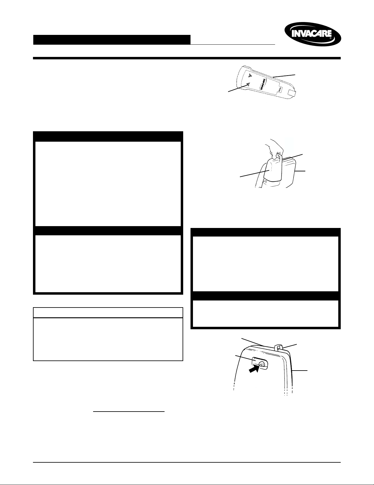
SAFETY SUMMARY
The following recommendations are made for the
safe installation of the Mounting Kit on the Reliant Bath Lift (RBL250).
GENERAL WARNING
DO NOT assemble or use this kit without
first reading and understanding this instruction sheet. If you are unable to understand the Warnings, Cautions or Instructions in this Instruction Sheet and in the
Owner's Operating and Maintenance
Manual (Part No. 1081003) provided with
the Bath Lift. contact a healthcare professional, dealer or technical personnel
before attempting to install this kit, otherwise, injury or damage may occur.
INSTALLATION WARNINGS
When installing or removing the Battery
pack ALWAYS hold the battery pack firmly,
otherwise injury or damage may result.
To prevent frame from tipping when raising
or lowering the seat, either suction the frame
to the floor or place one foot on the frame
base when removing/installing the seat.
This kit contains the following:
DESCRIPTION QTY
Suction Cups 2
End Plugs 4
Locking Clips 2
Rubber Pads 2
Instruction Sheet 1
Pendant
Up
FIGURE 1 - RAISING THE BATH LIFT
2. Remove the battery pack by grasping the handgrip
on battery pack and pulling upwards (FIGURE 2).
PULL UP TO
REMOVE
Battery Pack
FIGURE 2 - REMOVING THE BATTERY PACK
3. To release the seat, press and hold the spring loaded
chair release button (FIGURE 3).
To prevent pinching injury between seat
back and motor shroud when removing/
installing the seat, DO NOT grasp seat anywhere other than at the recess at the top
(FIGURE 3), the opening at the bottom of
the seat or the lip where the battery pack
was.
é
WARNING
Handgrip
Frame
CAUTION
DO NOT remove the seat until the bath Lift
is raised to the upper limit. Otherwise damage may occur.
Motor Shroud
Battery Pack
Recess
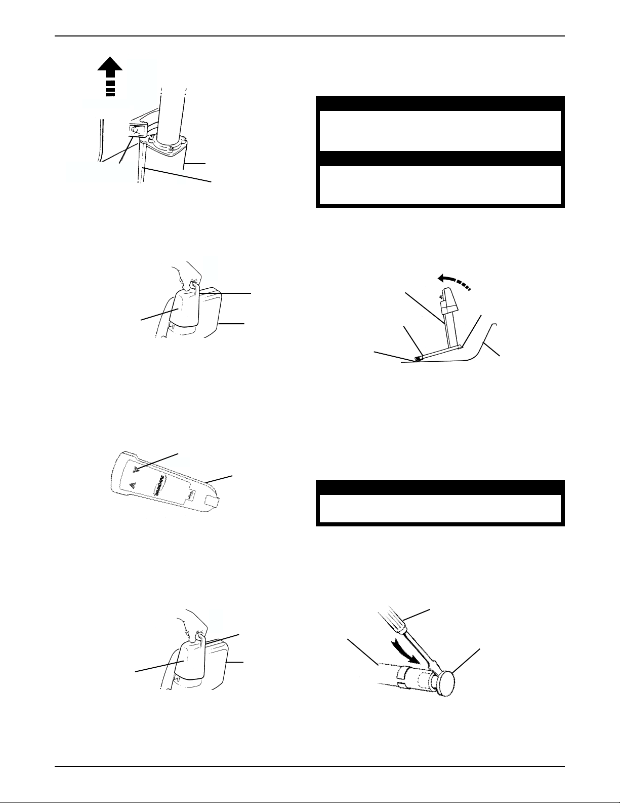
REPLACING THE BATH LIFT
MOUNTS
Removing the Bath Lift Seat (FIGURES 1-7)
NOTE: Refer to the GENERAL WARNINGS in the
SAFTY SUMMARY of this Instruction Sheet.
1. Raise the Bath Lift seat by pressing the UP (é) but-
ton on the pendant (FIGURE 1).
NOTE: The lift will automatically stop at the top and
bottom limits if UP/DOWN buttons are not released.
Seat
Spring Loaded
Chair Release
Button
FIGURE 3 - RELEASING THE SEAT
4. While holding the spring loaded chair release button with one hand, grasp the seat bottom firmly with
your other hand.
5. Lift the seat up until the slide block comes free of the
grooves on the Bath Lift frame to remove the seat
from the frame (FIGURE 4).
1
LIFT THE SEAT
Slide Block
FIGURE 4 - REMOVING THE SEAT
Frame
Groove
REMOVING THE BATH LIFT FROM
THE BATHTUB (FIGURE 8)
WARNING
Use proper lifting techniques to avoid injury. Keep back straight and bend knees
when lifting components of the Bath Lift.
CAUTION
ALWAYS release suction cups from bathtub
bottom BEFORE removing frame to prevent
damage to the frame or bathtub.
6. Install the battery pack by grasping the handgrip
and sliding the battery pack onto the charger connector on the frame (FIGURE 5).
PUSH DOWN
ê
NOTE: The battery pack should fit snugly and not
wobble.
7. Lower the Bath Lift by pressing the DOWN (ê)
NOTE: The lift will automatically stop at the top and
bottom limits if UP/DOWN buttons are not released.
8. Remove the battery pack by grasping the handgrip
TO INSTALL
Battery Pack
FIGURE 5 - INSTALLING THE BATTERY PACK
button on the pendant (FIGURE 6).
Down
FIGURE 6 - LOWERING THE BATH LIFT
on battery pack and pulling upwards (FIGURE 7).
Handgrip
Frame
Pendant
1. Tilt the frame forward towards the drain or gently pull up
on the suction cup loops to release the suction cups.
2. Remove frame from bathtub (FIGURE 8).
TILT FRAME
Frame
Suction Cup Loop
Suction Cup
FIGURE 8 - REMOVING THE BATH LIFT FROM
THE BATHTUB
FORWARDS
Rubber Pad
Bathtub
REPLACING SUCTION CUPS
(FIGURES 9-12)
1. Lean Bath Lift backwards so that the back of the frame
is resting on the floor.
WARNING
Always point the screwdriver away from
your body. Otherwise injury may occur.
2. Place screwdriver behind the lip of the EXISTING end
plug (FIGURE 9).
3. Use a hammer to gently tap the back of the screwdriver until the EXISTING end plug comes free.
PULL UP TO
REMOVE
Battery Pack
FIGURE 7 - REMOVING THE BATTERY PACK
é
handgrip
Frame
Screwdriver
Base Frame
End Plug
NOTE: Suction Cup
removed for clarity.
FIGURE 9 - REMOVING THE EXISTING END
PLUG
2
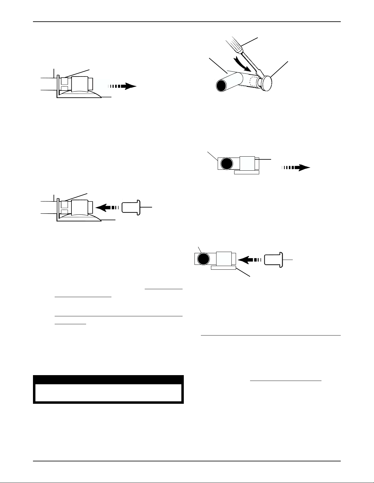
4. Twisting EXISTING suction cup from side, pull the the
suction cup off of the bath lift base frame (FIGURE 10).
Bath Lift
Base Frame
EXISTING Locking Clip
EXISTING Suction Cup
FIGURE 10 - REMOVING THE EXISTING
SUCTION CUP
5. Leave EXISTING locking clip on the bath lift base frame
(it is glued in place).
6. Install the NEW suction cup by reversing STEP 4.
7. Place NEW end plug into the bath lift base frame and
using a hammer gently tap the end plug securely into
position (FIGURE 12).
Base Frame
Locking Clip
New End
Suction Cup
FIGURE 11 - INSTALLING END PLUG
Plug
Screwdriver
Bath Lift
Base Frame
EXISTING End Plug
NOTE: Rubber Pad
removed for clarity.
FIGURE 12 - REMOVING THE EXISTING
END PLUG
4. Twisting EXISTING Rubber Pad from side, pull the the
suction cup off of the bath lift base frame (FIGURE 13).
Bath Lift Base Frame
EXISTING Rubber Pad
FIGURE 13 - REMOVING THE EXISTING
RUBBER PAD
5. Install the NEW rubber pad by reversing STEP 4.
6. Place NEW end plug into the bath lift base frame and
use a hammer to gently tap the end plug securely into
position (FIGURE 14).
8. Repeat STEPS 2-7 on second suction cup.
9. Tilt the Bath Lift foward so that it is resting in the
upright position.
10. Perform one (1) of the following:
A. Replace Rubber Pads, refer to
THE RUBER PADS in this instruction sheet.
B. Reinstall the Bath Lift into the bath tub, refer to
INSTALLING THE BATHLIFT INTO THE
BATH TUB in this instruction sheet.
REPLACING
REPLACING THE RUBBER PADS
(FIGURES 12-14)
1. Tilt Bath Lift foward so that it rests on the front portion of the frame and top edge of the top cover.
WARNING
Always point the screwdriver away from
your body. Otherwise injury may occur.
2. Place screwdriver behind the lip of the EXISTING end
plug (FIGURE 12).
3. Use a hammer to gently tap the back of the screwdriver until the EXISTING end plug comes free.
Bath Lift Base Frame
NEW End Plug
NEW RubberPad
FIGURE 14 - INSTALLING END PLUG
7. Repeat STEPS 2-6 on second rubber pad.
8. Tilt the Bath Lift back to the upright position.
9. Reinstall the Bath Lift into the bath tub, refer to
INSTALLING THE BATHLIFT INTO THE BATH TUB
in this instruction sheet.
INSTALLING THE BATH LIFT INTO
THE BATHTUB (FIGURE 15)
NOTE: Refer to the GENERAL WARNINGS in the
SAFTY SUMMARY of this Instruction Sheet.
1. Clean tub and wipe suction cups with a damp cloth.
2. Place the bath lift base frame in the bathtub (FIGURE 15).
3. Position the rear pads of the frame just in front of the
curve at the bottom of the back of the bath.
3

WARNING
Lifting column MUST be in lowest position
BEFORE installing frame to prevent tipping.
The frame should be placed into an EMPTY
bathtub.
Front of the Bathtub
(fixture end)
Suction Cup
Back of
the
Bathtub
Frame
2. Remove the battery pack by grasping the handgrip
on battery pack and pull upwards (FIGURE 17).
PULL UP TO
REMOVE
Battery
Pack
é
Frame
Rubber Pad
FIGURE 15 - INSTALLING THE BATH LIFT INTO
THE BATH TUB
Reinstall Seat onto Bath Lift Frame
(FIGURES 16-18)
NOTE: If necessary, reinstall the battery pack on the frame.
1. Raise the bath lift all the way up by pressing the
UP (é) button on the pendant (FIGURE 16).
NOTE: The lift will automatically stop at the top and
bottom limits if UP/DOWN buttons are not released.
Pendant
Up
FIGURE 16 - RAISING THE BATH LIFT
FIGURE 17 - REMOVING THE BATTERY PACK
3. Lower the seat onto the frame, ensuring that the slide
block on the back of the chair slides down the two (2)
grooves on the frame (FIGURE 18).
NOTE: The seat MUST be lowered onto the frame until
the spring loaded chair release button locks in place and
an audible "click" is heard.
4. Position the Bath Lift in the bath tub, refer to POSITIONING THE BATH LIFT FRAME IN BATH TUB in
this Instruction Sheet
LOWER
SEAT
Seat
Frame
Slide
Block
Groove
FIGURE 18 - INSTALLING THE SEAT
4

Positioning the Bath Lift Frame in the
Bathtub (FIGURE 19)
1. Position the frame to align the line on the entry/exit
side flap with the inside edge of the bathtub as
shown in the FRONT VIEW of FIGURE 19.
WARNING
The frame must be positioned so that the
side flap of the seat on the entry/exit side
of the bathtub is fully supported by the
side of the bathtub. The inside edge of
the bathtub MUST be aligned with the line
on this side flap.
2. Ensure the pads and suction cups are positioned
flat on the bottom of the bathtub.
NOTE: Pull up on suction cup loops to release suction cups from bathtub bottom.
3. Press firmly down onto the two (2) front suction cups
to attach the frame securely to the bottom of the bath.
Position of Line on Side Flap
Suction Cup
NOTE: Suction Cups and
Ruber Pads must be flat on
bottom of bathtub
FIGURE 19 - POSITIONING THE BATH LIFT IN THE BATHTUB
Suction Cup Loop
PRESS DOWN ON
SUCTION CUP
Side Flaps
Seat
Frame
Bathtub
Side Flap Hinge
Seat
Inside Edge
of Bathtub
PROPER POSITIONING OF
ENTRY/EXIT SIDE FLAP
Entry/Exit
Side Flap
5

NOTES
6

LIMITED WARRANTY
PLEASE NOTE: THE WARRANTY BELOW HAS BEEN DRAFTED TO COMPLY WITH FEDERAL LAW
APPLICABLE TO PRODUCTS MANUFACTURED AFTER JULY 4, 1975.
This warranty is extended only to the original purchaser/user of our products.
This warranty gives you specific legal rights and you may also have other legal rights which
vary from state to state.
Invacare warrants the products manufactured to be free from defects in materials and
workmanship for a period of one (1) year from the date of purchase. If within such
warranty period any such product shall be proven to be defective, such product shall
be repaired or replaced, at Invacare’s option. This warranty does not include any
labor or shipping charges incurred in replacement part installation or repair of any such
product. Invacare’s sole obligation and your exclusive remedy under this warranty
shall be limited to such repair and/or replacement.
For warranty service, please contact the dealer from whom you purchased your Invacare product. In the event you do not receive satisfactory warranty service, please write
directly to Invacare at the address on the back page, provide dealer’s name, address,
date of purchase, and indicate nature of the defect.
Invacare Corporation will issue a serialized return authorization. The defective unit or parts
MUST be returned for warranty inspection using the serial number, when applicable as
identification within 30 days of return authorization date. Do not return products to our
factory without our prior consent. C.O.D. shipments will be refused; please prepay shipping
charges.
LIMITATIONS AND EXCLUSIONS: THE FOREGOING WARRANTY SHALL NOT APPLY TO SERIAL
NUMBERED PRODUCTS IF THE SERIAL NUMBER HAS BEEN REMOVED OR DEFACED, PRODUCTS
SUBJECTED TO NEGLIGENCE, ACCIDENT, IMPROPER OPERATION, MAINTENANCE OR STORAGE, PRODUCTS MODIFIED WITHOUT INVACARE’S EXPRESS WRITTEN CONSENT (INCLUDING,
BUT NOT LIMITED TO, MODIFICATION THROUGH THE USE OF UNAUTHORIZED PARTS OR ATTACHMENTS; PRODUCTS DAMAGED BY REASON OF REPAIRS MADE TO ANY COMPONENT
WITHOUT THE SPECIFIC CONSENT OF INVACARE, OR TO A PRODUCT DAMAGED BY CIRCUMSTANCES BEYOND INVACARE’S CONTROL, AND SUCH EVALUATION WILL BE SOLELY DETERMINED BY INVACARE. THE WARRANTY SHALL NOT APPLY TO PROBLEMS ARISING FROM NORMAL WEAR OR FAILURE TO ADHERE TO THE INSTRUCTIONS IN THIS MANUAL.
THE FOREGOING WARRANTY IS EXCLUSIVE AND IN LIEU OF ALL OTHER EXPRESS WARRANTIES.
IMPLIED WARRANTIES, IF ANY, INCLUDING THE IMPLIED WARRANTIES OF MERCHANTABILITY
AND FITNESS FOR A PARTICULAR PURPOSE, SHALL NOT EXTEND BEYOND THE DURATION OF THE
EXPRESSED WARRANTY PROVIDED HEREIN AND THE REMEDY FOR VIOLATIONS OF ANY IMPLIED WARRANTY SHALL BE LIMITED TO REPAIR OR REPLACEMENT OF THE DEFECTIVE PRODUCT PURSUANT TO THE TERMS CONTAINED HEREIN. INVACARE SHALL NOT BE LIABLE FOR ANY
CONSEQUENTIAL OR INCIDENTAL DAMAGES WHATSOEVER.
SOME STATES DO NOT ALLOW EXCLUSION OR LIMITATION OF INCIDENTAL OR CONSEQUENTIAL DAMAGE, OR LIMITATION ON HOW LONG AN IMPLIED WARRANTY LASTS, SO THE ABOVE
EXCLUSIONS AND LIMITATIONS MAY NOT APPLY TO YOU.
THIS WARRANTY SHALL BE EXTENDED TO COMPLY WITH STATE OR PROVINCIAL LAWS AND
REQUIREMENTS.
7

Invacare Corporation www.invacare.com
USA
One Invacare Way Invacare is a registered trademark of Invacare Corporation.
Elyria, Ohio USA ©
44036-2125
1999 Invacare Corporation
800-333-6900 Form No. 98-328 Part No. 1085311 Rev A (1)-1/00
 Loading...