

r
l
Invacare® Storm
Powerchai
User's Manua

How can you get in touch with Invacare®?
If you have any questions or need support, please contact your authorised Invacare® Dealer, who has the
necessary know-how and equipment plus the special knowledge concerning your Invacare® product, and
can offer you all-round satisfactory service. Should you wish to contact Invacare® directly, you can reach us
in Europe at the following addresses and phone numbers.
Invacare® Deutschland GmbH
Dehmer Str. 66
D-32549 Bad Oeynhausen
Deutschland
(Kundendienst): +49 - (0) 5731 - 754 580
(Technische Hotline): +49 - (0) 5731 - 754 570
Fax (Kundendienst): +49 - (0) 5731 - 754 216
Fax (Technische Hotline):+49 - (0) 5731 - 754 208
Invacare®, SA
c/ Areny, s/n
Poligon Industrial de Celrà
17460 Celrà (Girona)
ESPAÑA
: +34 - (0) 972 - 49 32 00
Fax: +34 - (0) 972 - 49 32 20
Invacare® Ltd
South Road
Bridgend
Mid Glamorgan - CF31-3PY
United Kingdom
(Customer Service): +44 - (0) 1656 - 647 327
Fax (Customer Service): +44 - (0) 1656 - 649 016
Invacare® A/S
Invacare® POIRIER
Mecc San S.R.L.
Sdr. Ringvej 39
2605 Brøndby
Danmark
(Kundeservice): +45 - (0) 3690 0000
Fax (Kundeservice): +45 - (0) 3690 0001
Les Roches
F-37230 Fondettes
France
(Service Après-Vente):+33 - (0) 2 47 - 62 64 66
Fax (Service Après-Vente):+33 - (0) 2 47 - 42 12 24
Via Dei Pini, 35
I - 36016 Thiene (VI)
ITALIA
: +39 - (0) 445-380059
Fax: +39 - (0) 445-380034
2

Invacare® AS
Grensesvingen 9
0603 Oslo
Norge
(Kundeservice): +47 - 22 57 95 10
Fax (Kundeservice): +47 - 22 57 95 01
Invacare® PORTUGAL Lda
Rua Senhora de Campanhã, 105
4369-001 Porto
PORTUGAL
: +352-225105946
Fax: +352-225105739
Invacare® B.V.
Celsiusstraat 46
NL-6716 BZ Ede
The Netherlands
: +31 - (0) 318 - 69 57 57
Fax: +31 - (0) 318 - 69 57 58
Invacare® AB
Fagerstagatan 9
163 91 Spånga
Sverige
(Kundtjänst): +46 - (0) 8 761 70 90
Fax (Kundtjänst): +46 - (0) 8 761 81 08
sweden@invacare.com
Service
Invacare
JÄRFÄLLA
: +46 - (0) 8 – 621 08 44
Fax: +46 - (0) 8 – 621 08 45
Invacare.jarfalla@.swipnet.se
MÖLNDAL
Invacare® n.v.
Autobaan 14
8210 Loppem (Brugge)
BELGIUM
: +32 (50) 831010
Fax: +32 (50) 831011
: +46 - (0) 31 – 86 36 00
Fax: +46 - (0) 31 – 86 36 06
invacare.goteborg@swipnet.se
LANDSKRONA
: +46 - (0) 418 – 285 40
Fax: +46 - (0) 418 – 180 89
invacare.la@swipnet.se
OSKARSHAMN
: +46 - (0) 491 – 101 40
Fax: +46 - (0) 491 – 101 80
invacare.O-hamn@swipnet.se
3

Table of Contents
Chapter
1
2
3
4
5
6
7
Introduction .....................................................................................9
1.1 Important symbols in this manual.......................................................................................11
1.2 Type Classification and Area of Use ..................................................................................11
Safety Notes...................................................................................12
2.1 General Safety Notes .........................................................................................................12
2.2 Safety information with regard to care and maintenance...................................................15
2.3 Safety Information on Electromagnetic Interference..........................................................16
2.4 Safety Information on Driving and Freewheel Mode..........................................................17
2.5 Safety Information on Wheelchairs with a Lifter.................................................................19
2.6 Safety Information on Wheelchairs with Recaro Seats ......................................................20
The most important components.................................................21
Getting In and Out.........................................................................22
Driving............................................................................................23
5.1 Before driving for the first time............................................................................................23
5.2 Taking Obstacles................................................................................................................24
5.3 Driving up and down gradients...........................................................................................25
5.4 Parking and stationary........................................................................................................25
5.5 Hand brake .........................................................................................................................26
Pushing the wheelchair by hand..................................................27
6.1 Disengaging Motors............................................................................................................27
The Advanced Control System (ACS) .........................................28
7.1 The main parts of the Joystick Box.....................................................................................28
7.2 Main components of the Joystick Box ................................................................................30
7.2.1 Battery Charge Display....................................................................................................30
Page
4

Status Display..................................................................................................................31
7.2.2
7.2.3 Multi-Purpose Display......................................................................................................31
7.2.4 Symbols shown on the Multi-Purpose Display and their meanings.................................32
7.2.5 Joystick............................................................................................................................33
7.2.6 Socket for Programmer....................................................................................................33
7.2.7 Charging Socket..............................................................................................................34
7.2.8 Connection Socket for Supply Cable (Bus Cable)...........................................................34
7.3 Operating the Joystick Box.................................................................................................35
7.3.1 Switching the Joystick Box ON/OFF................................................................................35
7.3.2 Drive Away Interlock........................................................................................................36
7.3.3 Lighting / Flashers ...........................................................................................................37
7.3.4 Horn 38
7.3.5 Hazard Flashers ..............................................................................................................38
7.3.6 Selecting a Driving Mode.................................................................................................39
7.3.7 Driving and Steering........................................................................................................41
7.4 Adjusting electric options using the Joystick ......................................................................43
7.4.1 Select Adjustment Mode..................................................................................................44
7.4.2 Symbols of the Adjustment Options ................................................................................45
7.4.3 Select the option that needs to be adjusted ....................................................................46
7.4.4 Adjust option....................................................................................................................47
7.4.5 Deselect Adjustment Mode..............................................................................................47
7.5 Troubleshooting on the ACS Control System.....................................................................48
7.5.1 Error Codes .....................................................................................................................49
8
9
Adjustment Options of the Joystick Box....................................51
8.1.1 Adjusting the Joystick Box to length of the arm:..............................................................51
8.1.2 Swinging the Joystick Box out to the side (option):.........................................................51
8.1.3 Adjusting the height of the Joystick Box (option):............................................................52
8.1.4 Adjusting the height of the armrests................................................................................52
Seating systems............................................................................53
9.1 Standard and Kontur Seats ................................................................................................53
9.1.1 Adjusting the seat tilt........................................................................................................53
5

10
6
Backrest adjustment........................................................................................................55
9.1.2
9.1.3 Adjusting the headrest.....................................................................................................58
9.1.4 Adjusting the height of the armrests................................................................................59
9.1.5 Adjusting the height of the sideframes ............................................................................59
9.1.6 Seat width adjustment: ....................................................................................................59
9.1.7 Adjusting the pommel:.....................................................................................................60
9.2 Recaro Seats......................................................................................................................61
9.2.1 Recaro "N-Joy" and "Miles" (mechanically adjustable)...................................................61
9.2.2 Recaro Ergomed DS (electrically adjustable):.................................................................62
9.3 Invacare® Ultimate and Personal Special Seating Systems..............................................63
9.3.1 Adjusting the seat tilt........................................................................................................63
9.3.2 Seat version: Personal.....................................................................................................64
9.3.2.1 Adjusting the height of the back ...................................................................................64
9.3.2.2 Adjusting the backrest angle ........................................................................................65
9.3.3 Seat version: Ultimate......................................................................................................67
9.3.3.1 Adjusting the height of the back ...................................................................................67
9.3.3.2 Adjusting the backrest angle ........................................................................................68
9.3.3.3 Adjusting the inflatable cushions..................................................................................69
9.3.3.4 Removing the backrest.................................................................................................70
Footrests and Legrests.................................................................72
10.1 Footrests...........................................................................................................................72
10.1.1 Footrest (standard)........................................................................................................72
10.1.1.1 Removing the Footrest ...............................................................................................73
10.1.1.2 Footrest: Adjusting the Angle .....................................................................................74
10.1.1.3 Footrest: Adjusting the Length....................................................................................75
10.1.1.4 Footrest: Adjusting the Angle of the Footplate (Option).............................................75
10.2 Legrests............................................................................................................................76
10.2.1 Settable Legrest (Option)...............................................................................................76
10.2.1.1 Removing the Legrest.................................................................................................77
10.2.1.2 Settable legrest: Adjusting the Angle..........................................................................78
10.2.1.3 Settable legrest: Adjusting the Length........................................................................79
10.2.1.4 Settable legrest: Adjusting the Angle of the Footplate ...............................................79

11
12
13
Manually Adjustable Legrest .........................................................................................80
10.2.2
10.2.2.1 Removing the Legrest.................................................................................................81
10.2.2.2 Height Adjustment for Ergonomic Length Compensation ..........................................82
10.2.2.3 Manually adjustable legrest: Angle Adjustment..........................................................83
10.2.2.4 Manually adjustable legrest: Adjusting the Length.....................................................84
10.2.2.5 Manually adjustable legrest: Adjusting the Angle of the Footplate.............................84
10.2.3 Electrically Adjustable Legrest.......................................................................................85
10.2.3.1 Removing the Legrest.................................................................................................86
10.2.3.2 Height Adjustment for Ergonomic Length Compensation ..........................................87
10.2.3.3 Electrically adjustable legrest: Angle Adjustment.......................................................88
10.2.3.4 Legrest: Adjusting the Length.....................................................................................89
10.2.3.5 Legrest: Adjusting the Angle of the Footplate ............................................................89
10.3 Width Adjustment of the Legrests (Option):......................................................................90
Lifter (option).................................................................................91
11.1 Adjusting the seat tilt on a STORM with a Lifter Module..................................................92
11.2 Adjustment of the electric Lifter Module: ..........................................................................93
11.3 Automatic speed reduction:..............................................................................................94
11.4 Technical Specifications of the Lifter Module:..................................................................94
Electrical System...........................................................................95
12.1 Electronics Protection System..........................................................................................95
12.2 Batteries............................................................................................................................96
12.2.1 What you need to know about batteries........................................................................96
12.2.2 Charging the batteries ...................................................................................................98
12.2.3 Removing and fitting batteries.....................................................................................100
12.2.3.1 Removing and refitting the 70 Ah batteries ..............................................................101
12.2.3.2 Removing and fitting the 55 Ah batteries (old STORM model) ................................104
12.2.3.3 How to handle damaged batteries correctly.............................................................105
12.3 Lighting ...........................................................................................................................106
Repair Instructions......................................................................107
13.1 Replacing light bulbs.......................................................................................................107
13.2 Repairing a flat tyre.........................................................................................................109
7

14
15
16
17
Repairing a flat tyre (pneumatic tyres type 200 x 50)..................................................109
13.2.1
13.2.2 Repairing a flat tyre (pneumatic tyres type 3.00x4")....................................................111
13.2.3 Repairing a flat tyre (pneumatic tyres type 3.00-8")....................................................113
Care and maintenance................................................................115
Transport ......................................................................................118
15.1 Transferring the wheelchair to another vehicle...............................................................118
15.2 Securing the wheelchair for transport.............................................................................118
15.2.1 The Taxi Bar................................................................................................................119
15.2.2 Anchor ring, lateral (Option): .......................................................................................119
15.2.3 "Crash Kit" (Option): ....................................................................................................120
Technical Specifications.............................................................121
Inspections Performed................................................................126
8

1 Introduction
Dear Customer,
First we would to thank you for choosing an Invacare® product. We hope you will be satisfied with your
new Powerchair and that it will bring you much enjoyment.
This wheelchair combines attractive design with a new dimension in mobility and driving pleasure.
Thanks to its unique modular construction, the STORM can be easily adapted to almost any personal need:
• Our different seating systems (like the Invacare® Kontur Seat, Invacare® Ultimate and Personal
Seating Systems or the Recaro Seat) are designed to fit your personal needs and wishes.
• An optional Lifter Module provides the capability to increase the height of the seat by up to
approximately 30 cm!
• Powerful 6 and 10 km/h motors make driving a pleasure in both indoor and outdoor environments.
By adjusting the wheelbase and the seat depth, the driving characteristics of the Powerchair can be
•
optimised for you.
9

• The individually programmable Invacare® Advanced Control System (ACS) allows fine-tuning of all
driving characteristics.
• The compact design guarantees excellent manoeuvrability and easy transport.
• Thanks to a well thought-through concept, most special design requirements can be easily taken care of
at the time of prescription. Later retro-fitting is possible, however this requires more work and should be
performed by trained personnel.
• The orderly construction of the wheelchair make service and maintenance easy.
This User's Manual contains important information and instructions on the following subjects:
• Safety
• Operation
• Care and maintenance
Please familiarise yourself with these instructions before going for your first drive. We cannot be
held responsible for any damage or faults that result from failure to comply with the instructions
put forth in this manual.
10

1.1 Important symbols in this manual
WARNING: This symbol warns you of danger!
• Follow the instructions to avoid injury to the user or damage to the product!
NOTE:
This symbol indicates hints and suggestions which should help make operating the product
easier and point out special functions.
REQUIREMENTS:
• This symbol indicates a list of the different tools and other requirements you will need to do
certain maintenance work.
1.2 Type Classification and Area of Use
This wheelchair has been classified as class B (for indoor and outdoor areas). It has been
successfully tested for its safety according to German and international standards. When equipped
with an appropriate lighting system, the wheelchair is suitable to be driven on public roads.
WARNING: Danger of injury to occupant and damage to wheelchair if driver is not
mentally and physically able to keep full control of the vehicle at all times!
• If necessary, operation of the Powerchair must be performed by an attendant!
11

2 Safety Notes
• READ WELL BEFORE OPERATION!
2.1 General Safety Notes
Danger of injury if wheelchair is used in any other way than the purpose described in this
manual!
• Adhere strictly to the instructions in this User's Manual!
Danger of injury if the wheelchair is driven when ability to operate a vehicle is impaired by
medication or alcohol!
• Never drive the wheelchair under the influence of medication or alcohol!
Danger of damage or injury if wheelchair is accidentally set into motion!
• Switch the wheelchair off before you get in, get out or handle unwieldy objects!
• Be aware that there are only the motor brakes to stop your wheelchair. When the motors are
disengaged, these brakes are automatically deactivated. For this reason, pushing the
wheelchair by an attendant is only recommended on flat surfaces, never on gradients. Never
leave your wheelchair on a gradient with its motors disengaged. Always re-engage the
motors immediately after pushing the wheelchair.
12

Danger of injury if the On/Off Button is pressed while the wheelchair is in motion, due to it
coming to an abrupt, sharp stop!
• If you have to brake in an emergency, simply release the joystick which will bring you to a
halt!
Danger of injury when transferring wheelchair to another vehicle for transport with the
occupant seated in it!
• It is always better to transfer the wheelchair to another vehicle without the occupant seated in
it!
• In case the wheelchair does need to be transferred to another vehicle over a ramp with the
occupant seated in it, always have an attendant stand behind the wheelchair during transfer
to ensure it does not tip over backwards!
Danger of injury, if the wheelchair is used as a vehicle seat without a special restraining
system!
• Only ever use the wheelchair as a vehicle seat in connection with a Wheelchair Restraint
System and with the safety belts of the transporting vehicle! Make sure to follow the
instructions and recommendations issued by the Restraint System's manufacturer!
Danger of injury if maximum permissible load is exceeded!
• Do not exceed the maximum permissible load (see technical specifications)!
Danger of injury if legrests break due to use as a stepping board!
• Do not use the legrests as a stepping board when getting in and out of the wheelchair!
13

Danger of injury due to wrong lifting or dropping of heavy components!
• When maintaining, servicing or lifting any part of your wheelchair, take into account the
weight of the individual components especially the batteries! Be sure at all times to adopt the
correct lifting posture and ask for assistance if necessary!
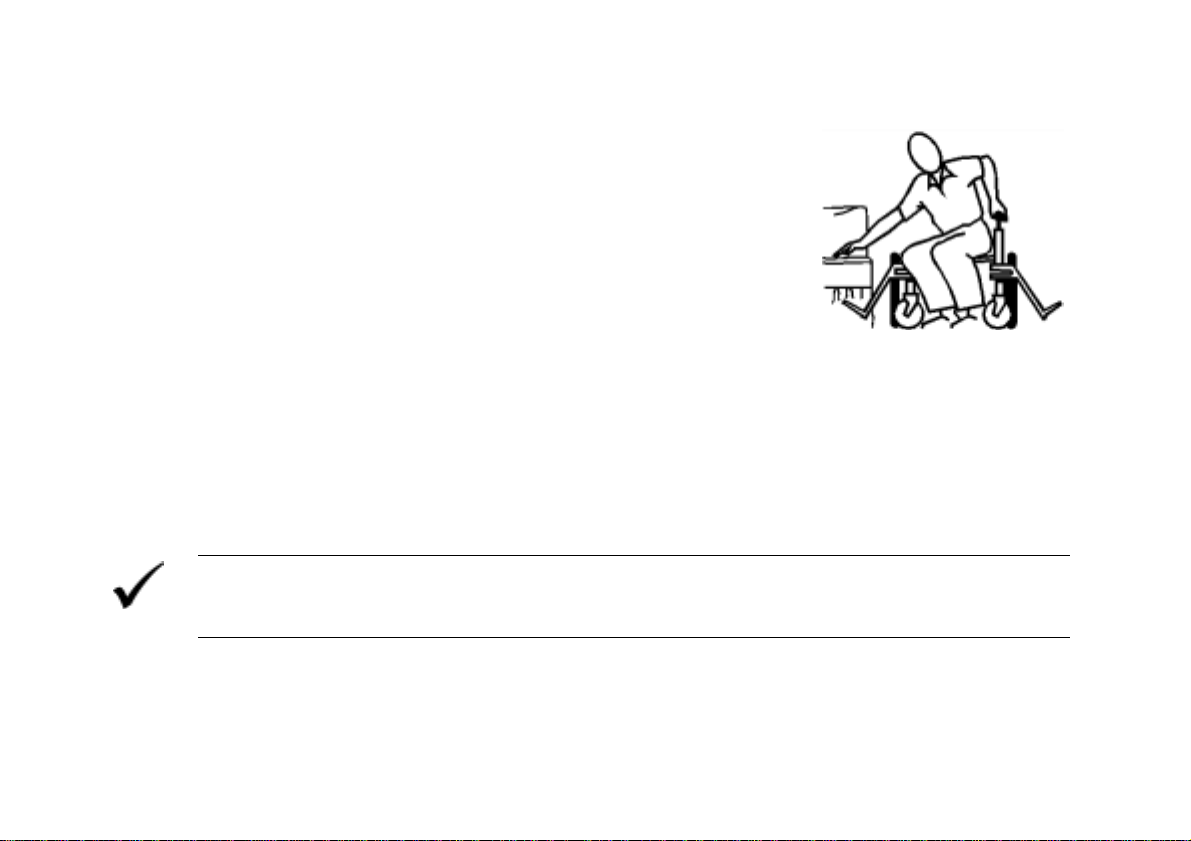
Danger of falling out of the wheelchair.
• Do not slide forward on the seat, do not lean forward between your knees, do not lean
backwards out over the top of the backrest, for example to reach an object.
• If restraining systems are installed (such as seat belts), use them each time you drive the
wheelchair.
• When changing over to a new seat, position the wheelchair as close as possible to the new
seat.
Danger of injury by moving parts!
• Make sure that no injury is incurred by moving parts of the wheelchair, like wheels or one of
the Lifter Modules (if fitted), especially when children are around!
Danger of fire or breaking down due to electric devices being connected!
• Do not connect any electric devices to your wheelchair that are not expressly certified by
Invacare® for this purpose! Have all electrical installations done by your authorised
Invacare® Dealer!
14

2.2 Safety information with regard to care and maintenance
Danger of accident and loss of guarantee if maintenance is insufficient!
• For reasons of safety and in order to avoid accidents which result from unnoticed wear, it is
important that this electric vehicle undergoes an inspection once every year under normal
operating conditions (see inspection plan contained in service instructions)!
• Under difficult operating conditions such as daily travel on steep slopes, or in the case of use
in medical care cases with frequently changing wheelchair users, it would be expedient to
carry out intermediate checks on the brakes, accessories and running gear!
• If the vehicle is to be operated on public roads, the vehicle driver is responsible for ensuring
that the vehicle is in an operationally reliable condition! Inadequate or neglected care and
maintenance of the vehicle will result in a limitation of the manufacturer's liability!
15

2.3 Safety Information on Electromagnetic Interference
This electric vehicle was successfully tested in accordance with International standards as to its
compliance with Electromagnetic Interference (EMI) Regulations. However, electromagnetic fields,
such as those generated by radio and television transmitters, and cellular phones, can influence
the functions of electric vehicles. Also, the electronics used in our vehicles can generate a low level
of electromagnetic interference, which however will remain within the tolerance permitted by law.
For these reasons we ask you to please observe the following precautions:
WARNING: Danger of malfunction due to electromagnetic interference!
• Do not switch on or operate portable transceivers or communication devices (such as radio
transceivers or cellular phones) when the vehicle is switched on!
• Avoid getting near strong radio and television transmitters!
• In case the vehicle should be set in motion unintentionally or the brakes are released, switch
it off immediately!
• Adding electrical accessories and other components or modifying the vehicle in any way can
make it susceptible to electromagnetic interference. Keep in mind that there is no sure way to
determine the effect such modifications will have on the overall immunity of the electronic
system!
• Report all occurrences of unintentional movement of the vehicle, or release of the electric
brakes to the manufacturer!
16

2.4 Safety Information on Driving and Freewheel Mode
Danger of injury if the wheelchair tips over!
• Only ever negotiate gradients of up to the maximum defined in the Technical Specifications
and only with the backrest and seat tilt in an upright position!
• Only ever drive downhill at a maximum of 2/3 of the top speed! Avoid abrupt braking or
accelerating on gradients!
• If at all possible, avoid driving on slippery surfaces (such as snow, gravel, ice etc.) where
there is a danger of you losing control over the vehicle, especially on a gradient! If driving on
such a surface is inevitable, then always drive slowly and with the utmost caution!
• Never attempt to overcome an obstacle when on an uphill or downhill gradient!
• Never attempt to drive up or down a flight of steps with your wheelchair!
• Always approach obstacles straight on! Ensure that the front wheels and rear wheels move
over the obstacle in one stroke, do not stop halfway! Do not exceed the maximum obstacle
height (see Technical Specifications)!
• Avoid shifting your centre of gravity as well as abrupt joystick movements and changes of
direction when the wheelchair is in motion!
• Never use the wheelchair to transport more than one person!
• Do not exceed the maximum permissible load!
• Note that the wheelchair will brake or accelerate if you change the Driving Mode whilst the
wheelchair is in motion!
17

Danger of breaking down in adverse weather conditions, i.e. extreme cold, in an isolated
area!
• If you are a user with severely limited mobility, we advise that in the case of adverse weather
conditions DO NOT attempt a journey without an accompanying attendant!
Danger of injury if your foot slides off the footrest and gets caught underneath the
wheelchair when it is in motion!
• Make sure each time before you drive the wheelchair that your feet are squarely and securely
in place on the footplates, and that both legrests are properly locked into place!
Danger of injury if you collide with an obstacle when driving through narrow passages
such as doorways and entrances!
• Drive through narrow passages in the lowest Driving Mode and with due caution!
18

2.5 Safety Information on Wheelchairs with a Lifter
IMPORTANT - IF YOUR WHEELCHAIR IS EQUIPPED WITH A LIFTER:
Danger of injury if the wheelchair tips over!
• Never exceed the maximum permissible load (see Technical Specifications)!
• Avoid dangerous driving situations when the lifter is in a raised position, such as trying to
overcome obstacles like kerbs or driving up or down steep gradients!
• Never lean out of the seat when the lifter is raised!
• Inspect the lifter module at least once a month to make sure the automatic speed reduction
function, which reduces the speed of the wheelchair when the lifter is raised, is working
properly (see chapter on lifter)! Notify your authorised dealership immediately if it is not
working properly!
Danger of injury by moving parts!
• Never let objects get caught in the space underneath a raised lifter!
• Make sure that neither you nor anyone else is injured by placing hands, feet other body
extremities under the raised seat!
Danger of malfunction of the Lifter Module!
• Inspect the lifter module at regular intervals to make sure there are no foreign objects or
visible damage, and to make sure the electric plugs are firmly inserted into their sockets!
19
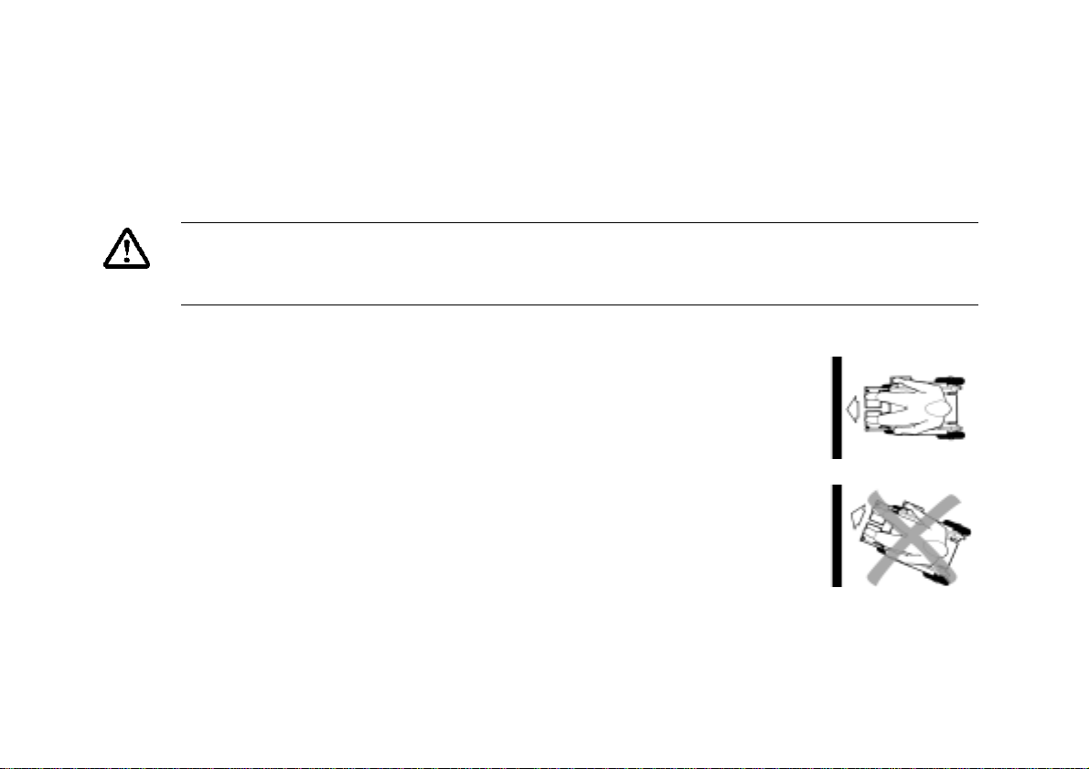
2.6 Safety Information on Wheelchairs with Recaro Seats
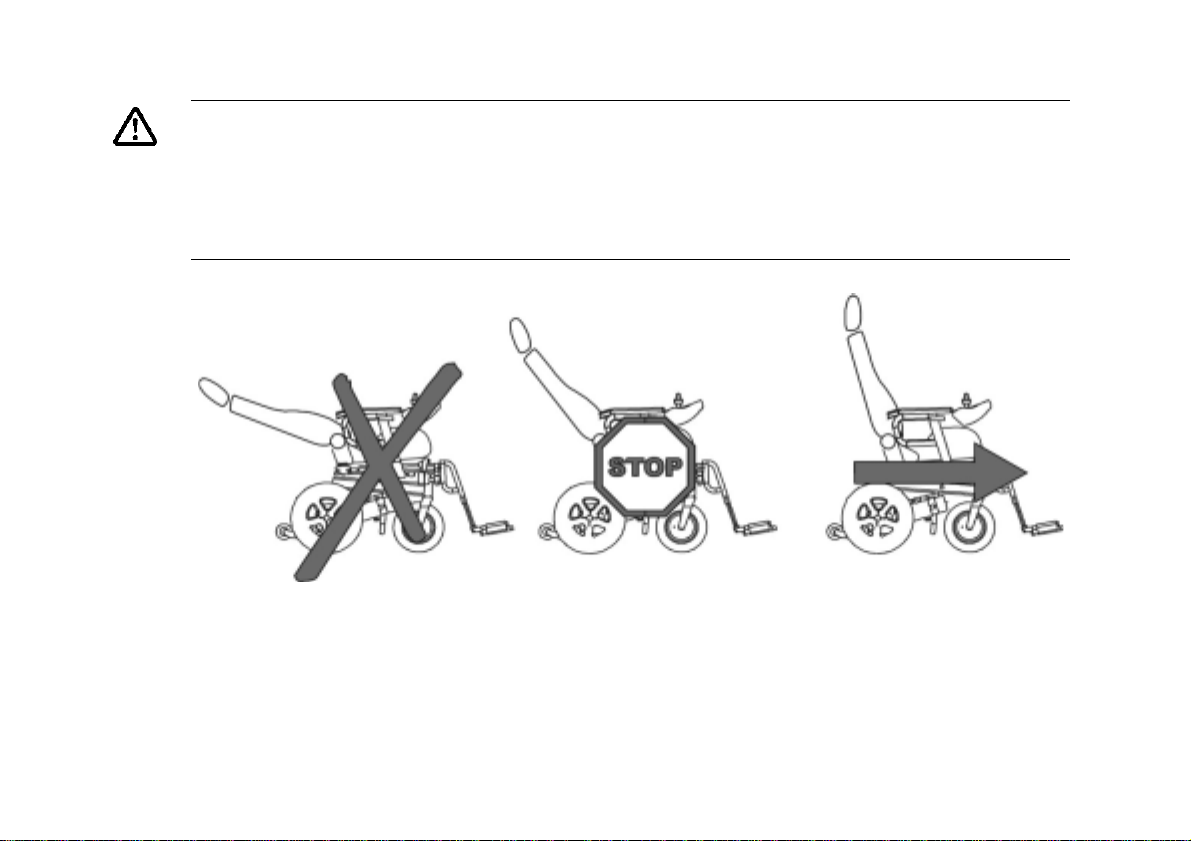
Danger of injury if the wheelchair tips over!
The centre of gravity of a Recaro seat is higher than that of other seats. The Recaro seat is
also heavier than other seating systems. The backrests of RECARO seats can be leaned
back 90°. For these reasons there is an increased risk of tipping over!
• Never lean the backrest backward more than 30° degrees, and never exceed 15° when
driving the wheelchair!
20
More than 30° 15°-30° 0°-15°
NEVER!! Standstill! Driving
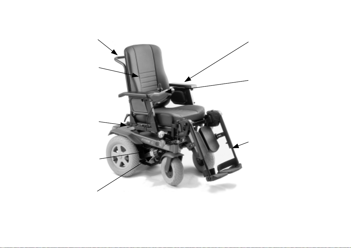
3 The most important components
Declutching Lever
Push Handle
Backrest
Batteries
Motor
Armrest
Joystick
Footrests
21
4 Getting In and Out
Getting in:
• Position the wheelchair as near to your seat as possible. If
necessary, this can be done by an attendant.
• Switch your wheelchair off.
• Activate the hand brake (if your wheelchair has one).
• Remove the armrest our flip it upwards.
• Now slide over onto the wheelchair.
Getting out:
• Position the wheelchair as near to the new seat as possible.
• Switch your wheelchair off.
• Remove the armrest our flip it upwards.
• Now slide over onto the new seat.
NOTE
If you do not have sufficient muscle strength to change over by yourself, then do not hesitate to
ask someone for assistance. Use a board to slide over on, if one is available.
22

5 Driving
5.1 Before driving for the first time...
Before you take your first trip, you should familiarise yourself well with the operation of the vehicle
and with all operating elements. Take your time to test all functions and driving modes.
NOTE:
If installed, use the restraining systems (seat belts) each time you use the vehicle.
Sitting Comfortably = Driving Safely
Before each trip, make sure that:
• You are within easy reach of all operating controls.
• The battery charge is sufficient for the distance intended to be covered.
• The seatbelt is in perfect order.
23
5.2 Taking Obstacles
Your wheelchair can overcome obstacles and kerbs with the following heights.
• STORM with front wheel type 200x50: 4 cm
• STORM with front wheel type 3.00x4”: 6 cm
• STORM with kerb climber: 10 cm
CAUTION: Danger of Tipping Over!
• Never approach obstacles at an angle!
• Put your backrest into an upright position before climbing an obstacle!
Driving up over an obstacle
• Approach the kerb or obstacle slowly head-on. Shortly before the front
wheels or kerb-lifter touch the obstacle, increase the speed and reduce
only after also the rear wheels have climbed the obstacle.
Correct
24
Driving down off of an obstacle
• Approach the kerb or obstacle slowly head-on. Before the front wheels
touch the obstacle, reduce the speed and keep it until also the rear wheels
have climbed the obstacle.
Incorrect

5.3 Driving up and down gradients
The STORM can safely climb gradients of up to 18%.
When driving up or down gradients you should always observe the following precautions:
WARNING: Danger of tipping over!
• Only ever drive downhill at a maximum of 2/3 of the top speed!
• Always return the backrest of your seat or the seat tilt to an upright position before ascending
slopes! We recommend that you position the seat backrest or the seat tilt slightly to the rear
before descending slopes!
• Never attempt to ascend or descend a slope on slippery surfaces or where there is a danger
of skidding (such as wet pavement, ice etc)!
• Avoid trying to get out of the vehicle on an incline or a gradient!
• Always drive straight in the direction the road or path you are on goes, rather than attempting
to zigzag!
• Never attempt to turn around on an incline or a slope!
5.4 Parking and stationary
When you leave your wheelchair standing still for a longer period of time:
• Switch the Joystick Box OFF (ON/OFF Button).
When parking your vehicle:
• Activate the Drive Away Interlock, if available.
25

5.5 Hand brake
The 10 Km/h version of the STORM is equipped with an additional
hand brake. The brake lever is normally mounted on the opposite
side from the Joystick Box. Alternatively, the brake lever can be
mounted on the same side as the Joystick Box with a special holder.
• To activate the brakes push the brake lever forward, to release
pull the lever backwards.
26
6 Pushing the wheelchair by hand
6.1 Disengaging Motors
The motors of the wheelchair are equipped with automatic brakes, preventing that the wheelchair
starts rolling out of control when the joystick box is switched off. When pushing the wheelchair, the
magnetic brakes must be disengaged.
Danger of the vehicle running away!
• When the motors are disengaged (for push operation), the electromagnetic motor brakes are
deactivated! When the vehicle is parked, the levers for engaging and disengaging the motors
must without fail be locked firmly into the "DRIVE" position (electromagnetic motor brakes
activated)!
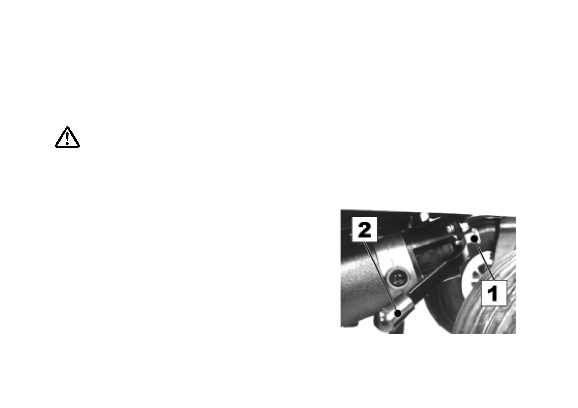
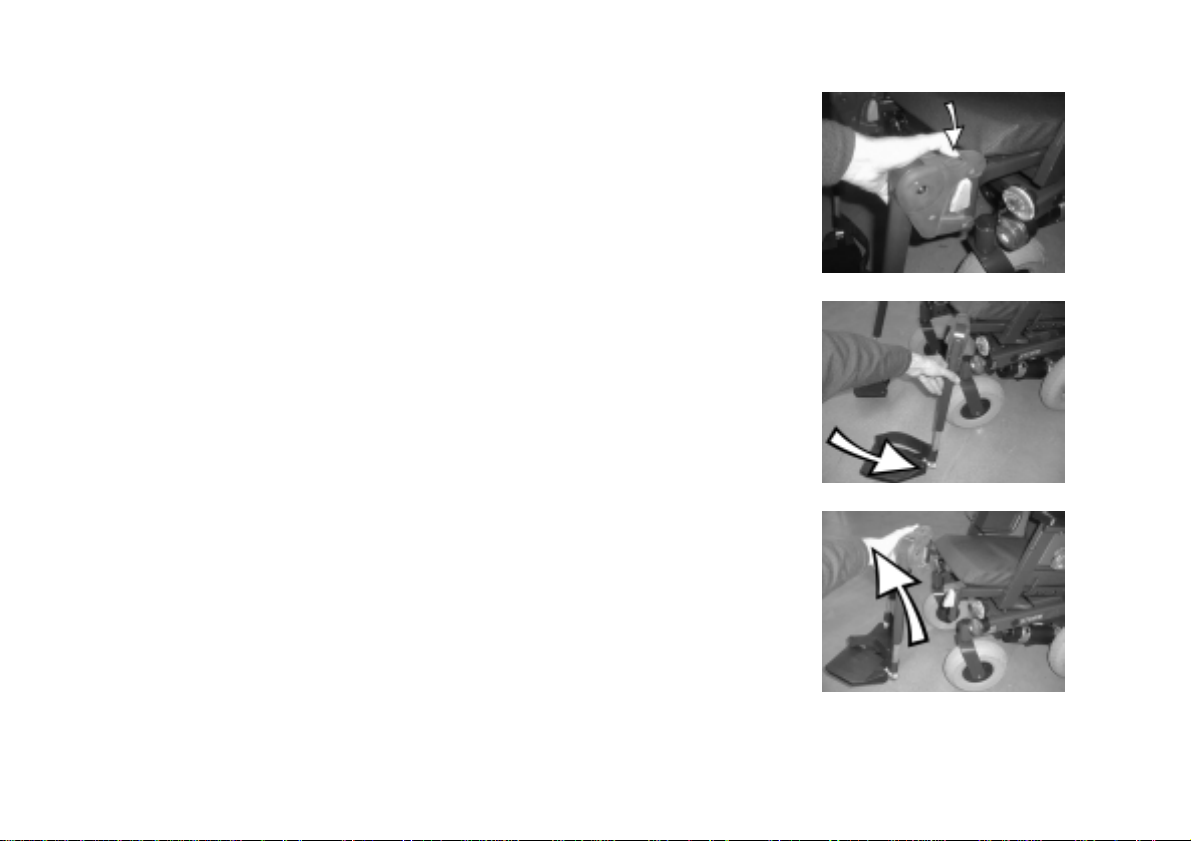
The lever, with which the motors are disengaged,
is located on the right motor.
Disengaging the motors:
• Switch off the remote.
• Pull the safety bolt (1) forward.
• Pull the declutching lever (2) upwards.
Re-engaging the motors:
• Push the declutching lever down. The safety bolt
locks automatically back in place.
27
7 The Advanced Control System (ACS)
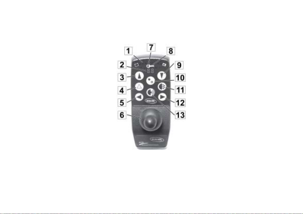
7.1 The main parts of the Joystick Box
1) Battery Charge Display
2) Driving and Adjustment
Mode Display
3) Shift Up Driving Mode
4) Hazard Flasher Button
5) Left Flasher
6) Joystick
7) Status Display
8) Drive Away Interlock
9)Shift Down Driving Mode
10) ON/OFF
11) Light
12) Right Flasher
13) Horn
28
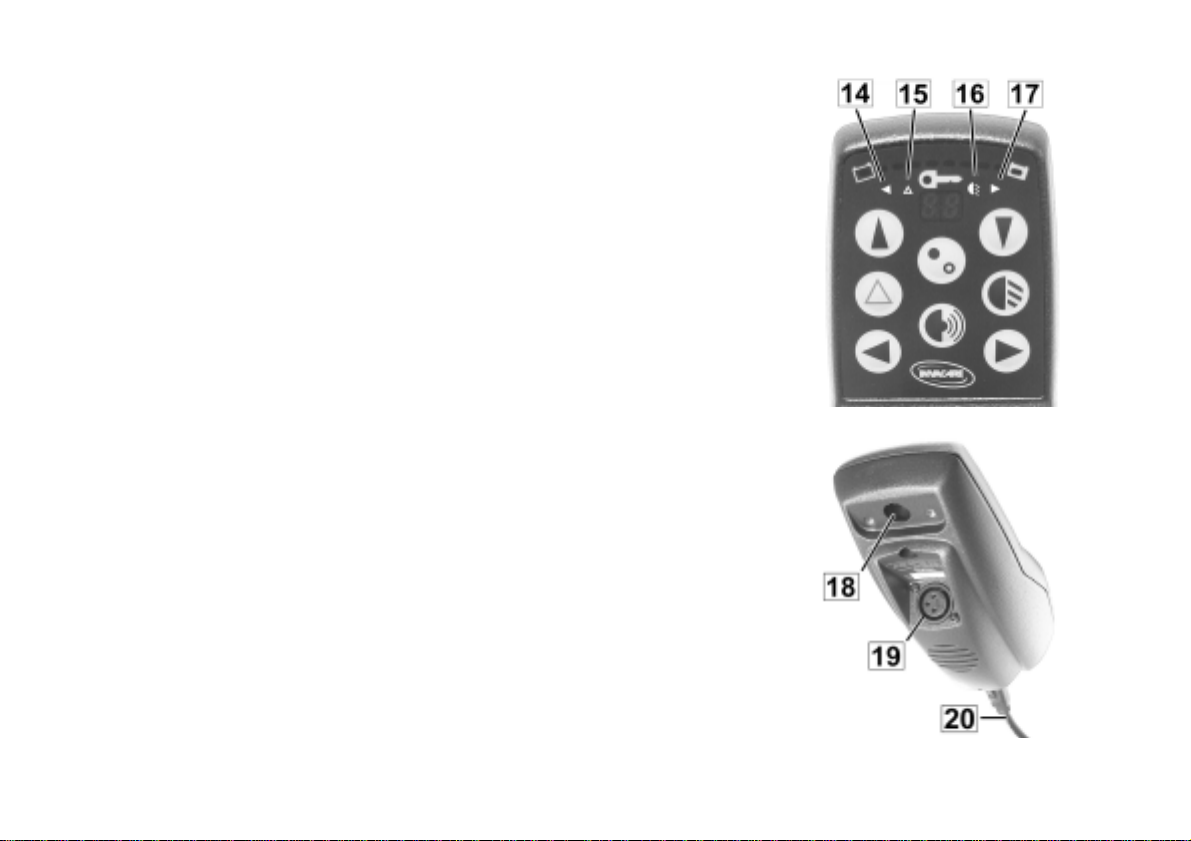
The Pilot Lights on theJoystick Box:
• Left and Right Flashers (14+17)
• Hazard Flashers (15)
• Vehicle Lighting (16)
Pilot lights
On the bottom of the joystick box you will find:
•
Socket for Programmer (18)
•
the Charging Socket (19)
• Connection Socket for Supply Cable (20)
29

7.2 Main components of the Joystick Box
7.2.1 Battery Charge Display
The battery charge display (1) shows you the current charge status
of the batteries.
It is subdivided into 10 different-coloured LEDs:
2 x red, 4 x yellow and 4 x green.
The decreasing battery charge, and thus the Powerchair's
decreasing travelling range, is indicated by the individual diodes
going out.
Meaning of the Display:
• All diodes illuminated: full travelling range = batteries fully
charged
• Only the red diodes illuminated: Diminished travelling range =
charge batteries at end of trip
• Both of the red diodes flash: very low travelling range = charge
batteries as soon as possible
• Only one red diode flashes: Battery reserve = charge batteries
immediately!
The travelling range on battery reserve is very low. After a certain
travelling time, the electronics will switch off the drive automatically
and bring the Powerchair to a standstill = full discharge protection.
Battery Charge Display
30

7.2.2 Status Display
The ON/OFF LED (7) also functions as a Status Display or Error
Display. Flashing of the display indicates a malfunction of the
electrical equipment.
The cause of the malfunction is indicated by a flash code.
(Error codes see Chap. "Error Codes" on page 49.)
The ACS Joystick Box monitors the following functions:
• Monitoring the electronics
• Monitoring the electrical components
• Monitoring the power supply
7.2.3 Multi-Purpose Display
Using the Joystick Box, you can select a range of different electrical
adjustment options.
The symbols shown on the Multi-Purpose Display (2) indicate which
adjustment option (mode) is active at the moment.
Status Display
Multi-Purpose Display
31

7.2.4 Symbols shown on the Multi-Purpose Display and their meanings
= Driving Mode (select Driving Modes 1 - 5)
= Adjustment of Electric Options*
= Reduces driving speed when Lifter is raised or when the seat is not in an
upright position
* These symbols only appear if your wheelchair is equipped with the
NOTE
For more information on the individual symbols see chapter 7.4.2 on page 45.
corresponding electrical adjustment options.
32

7.2.5 Joystick
With the Joystick (6) you can:
• Drive and steer
• Select and adjust electric actuators (like powered legrests).
Driving speed and steering movement depend on the movement of
the joystick. The regulation of speed and steering direction is
continuous.
• Move Joystick to its furthest position in any direction = Maximum
of selected top forward and cornering speed.
7.2.6 Socket for Programmer
This socket (18) is located on the bottom of the joystick box and
serves to connect the programmer.18
The ACS programming can be modified using a programmer.
Joystick
Socket for Programmer
33

7.2.7 Charging Socket
This socket (19) is also located on the bottom of the joystick box and
serves to connect the battery charger.
7.2.8 Connection Socket for Supply Cable (Bus Cable)
The connection cable serves the power supply of the joystick box
and the data transfer from the joystick box to the main module.
The plug of the connection cable is secured against detachment of
the plug connection by a safety catch (20).
Charging Socket
Bus Cable
34

7.3 Operating the Joystick Box
7.3.1 Switching the Joystick Box ON/OFF
Switching ON:
Switching ON/OFF
• Press the ON/OFF Button (10) once.
Displays:
• The Status Display in the Key-Symbol lights up.
• The battery charge display showing the current charge status.
• The Driving Mode Display showes the selected Driving Mode.
Switching OFF:
• Press the ON/OFF Button (10) once again.
All displays will be extinguished.
NOTE
If the wheelchair is not ready to go when switched on, please check:
• the drive-away lock. 7.3.2).
• the Status Display (Chap. 7.2.2); Error codes (Chap. 7.5.1).
NOTE
A separate, independent switch for switching on the Joystick Box is also available as an option.
35

7.3.2 Drive Away Interlock
The ACS is protected against unauthorised use by an electronic
drive-away interlock. A sensor is located under the Key-Symbol. The
Drive Away Interlock is activated and deactivated by touching the
sensor area (8) with the magnetic key.
Activating the drive-away lock:
• Switch the Joystick ON.
• Touch the sensor area (8) with the end of the magnetic key (A).
The signal horn will sound once briefly. The drive-away lock is
activated.
Deactivating the Drive Away Interlock:
• Switch the Joystick ON.
• Touch the sensor area (8) with the end of the magnetic key (A).
Drive Away Interlock
Magnetic Key
36

7.3.3 Lighting / Flashers
Switching the lights on:
• Press the Lights Button (11) on the remote once. The Lighting-
LED (16) on the display lights up.
Switching the lights off:
• Press the Lights Button on the remote once again. The Lighting-
LED (16) on the display goes out.
Activating the flashers:
• Press either the right or left Flasher Button (5 / 12) once briefly.
The Flasher-LED (14 / 17) on the display lights up for the
selected direction.
Deactivating the flashers:
• Press the Flasher Button (5 / 12) briefly once again. The
Flasher-LED (14 / 17) on the display goes out.
Switching the lights ON
and OFF
Activating and
deactivating the flashers
37

7.3.4 Horn
• Press the Horn Button (13). the horn sounds for as long as the
button is pressed.
7.3.5 Hazard Flashers
Activating the Hazard Warning Flasher:
• Press the Hazard Warning Flasher Button (4) once briefly. The
Hazard Flasher is activated. The Hazard Flaher-LED (15) on the
display lights up.
Deactivating the flashers:
• Press the Hazard Warning Flasher Button once again. The
Hazard Flasher is deactivated. The Hazard Flaher-LED (15) on
the display goes out.
Horn
Activating and
deactivating the Hazard
Flasher
38

7.3.6 Selecting a Driving Mode
"Driving Mode" means more than just "how fast". The Driving
Mode encompasses:
• Acceleration
• Forward speed
• Backward speed
• Cornering speed
The Multi-Purpose Display (2) indicates which mode the wheelchair
is currently in.
Different Driving Modes can be selected using the buttons (3 + 9) to
the right and left of the display.
The Driving Mode has 5 levels:
Level 1 = very slow driving characteristics, reduced end-velocity
to
Level 5 = dynamic driving characteristics, highest end-velocity
Driving Mode Buttons
39

Shifting up from Driving Mode 1 - 5:
Switching Driving Modes
• Press the left button (3) as many times as necessary, until the
desired Driving Mode is reached. The display (2) shows the
selected Driving Mode.
Switching down from Driving Mode 5 - 1:
• Press the right button as many times as necessary, until the
desired Driving Mode is reached. The display (9) shows the
selected Driving Mode.
NOTE
The electronics of the ACS has been programmed at the factory with default values. Individual
programming, tailored to your specific requirements, can be performed by your authorised
Invacare® Dealer.
40
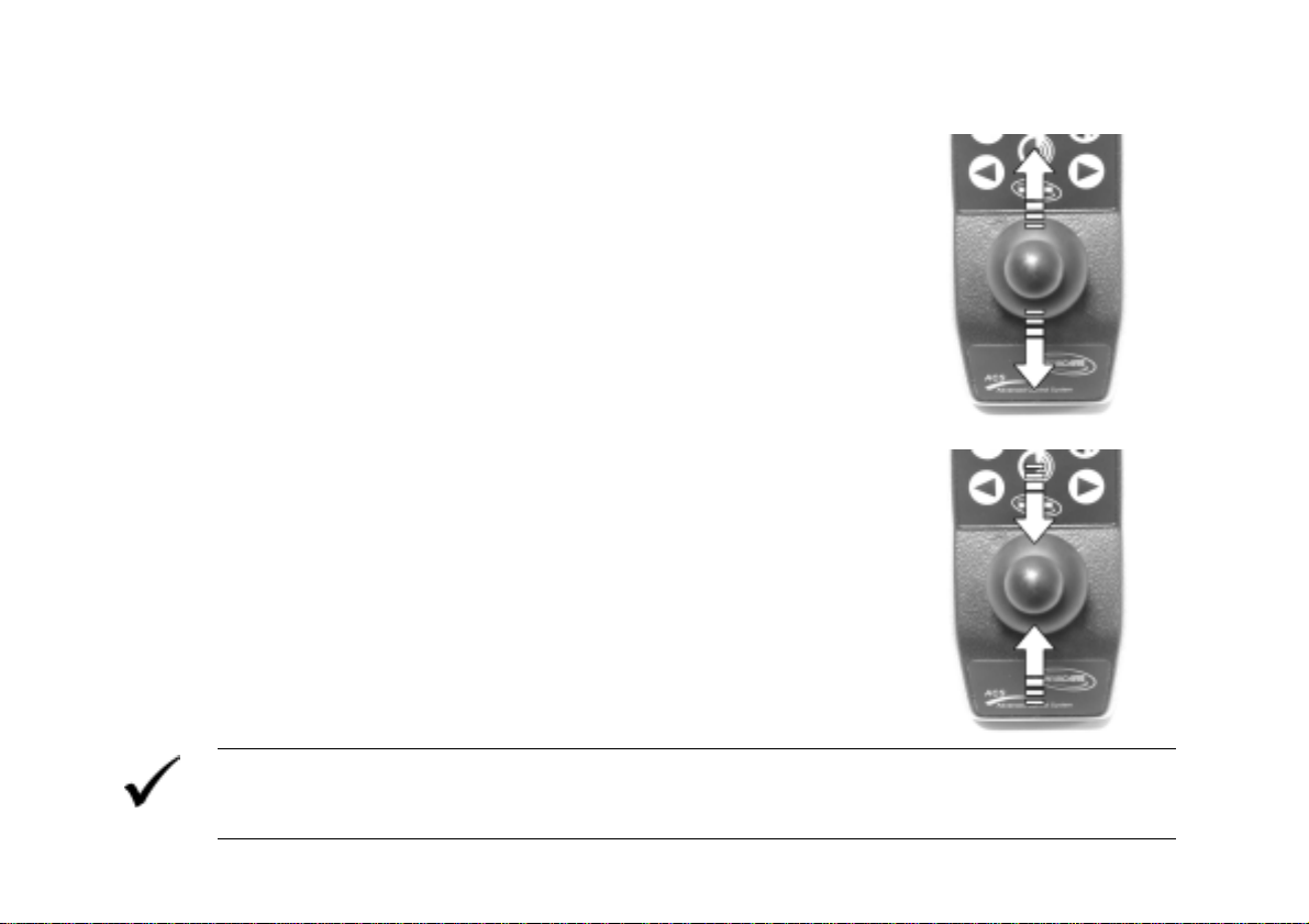
7.3.7 Driving and Steering
Driving forwards
Forward and Backwards
• Move joystick forward. The movement of the joystick determines
the driving speed.
Driving backwards
• Move joystick backwards. The movement of the joystick
determines the driving speed.
Braking
Braking
• Move joystick back to centre position.
NOTE
In dangerous situations it is sufficient to release the joystick. It will automatically return to its
centre position. The wheelchair will brake.
41

Cornering
Cornering
• Move the joystick in the desired direction whilst driving forward
or backwards. The movement of the joystick determines the
cornering speed.
Turning on the spot
Turning on the spot
• Move the joystick in the desired direction (left/right) WITHOUT
forward or reverse speed.
42

7.4 Adjusting electric options using the Joystick
Electric seat tilt, backrest angle, lifter and legrests can be adjusted
using the Joystick (6).
To be able to adjust the individual electric options, the Joystick Box
must be switched from driving mode to adjustment mode.
The Adjustment Symbols are displayed on the Multi-Purpose Display
(2) of the Joystick Box.
NOTE
Electric adjustment options can also be controlled independently from the Joystick Box using a
separately available control device.
Joystick and MultiPurpose Display
43

7.4.1 Select Adjustment Mode
• Press the right or left buttons (3+9) repeatedly until
the symbol shown at right appears on the display
(L).
• Push Joystick (6) to the right or left (1+2) until the
Adjustment Mode Symbol appears on the left
display (L).
• By pushing the Joystick forward (3) the adjustment
is activated.
Symbol
Symbol
Select symbols
Select Adjustment Mode
44

7.4.2 Symbols of the Adjustment Options
The symbol depicted on the right display (R) shows which option be can adjusted.
The individual options are designated by the following symbols:
seat tilt backrest
angle
left
legrest
both
Legrests
right legrest
lifter
45

7.4.3 Select the option that needs to be adjusted
Select:
• Push Joystick (6) once to the right or left. The flashing bar (✴) in
the symbol on the right display (R) shows which option can be
adjusted.
By pushing the Joystick once again in the same direction, the next
symbol can be selected. Repeat the procedure until the symbol of
the option that you would like to adjust appears on the display.
Select option that needs
be adjusted
46
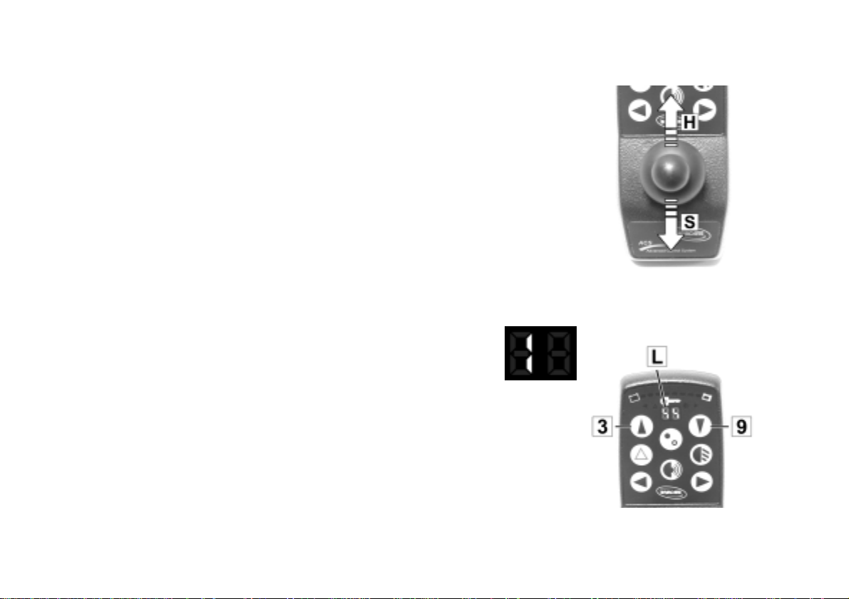
7.4.4 Adjust option
• Raise option (H) by pushing the Joystick forward.
• Lower option (S) by pulling the Joystick backward.
7.4.5 Deselect Adjustment Mode
• Press the right or left buttons (3+9) repeatedly until
the Driving Mode Symbol appears on the left
display (L).
Symbol
Adjust option
Symbol on the MultiPurpose Display
47

7.5 Troubleshooting on the ACS Control System
Wheelchair slows down or doesn't move
Check: Possible cause: Direct remedy: Further action (s):
Status display on
joystick box
extinguished?
Status display on
joystick box flashing?
Red LED in battery charge display and status display flashing, driving mode display
showing a horizontal bar.
Check: Possible cause: Direct remedy: Further action (s):
• Power supply
interrupted.
• Battery fully
discharged.
• Battery defective. • Replace battery. • Contact authorised
• Various causes. • Check error code. • See Chapter 7.5.1
• Battery
discharged.
• Check plug
connection at
joystick box.
• Charge battery. • See operating
• Charge battery. • See operating
• Contact authorised
dealer.
instructions of
charger.
dealer.
instructions of
charger.
48

7.5.1 Error Codes
The ACS electronics are capable to clear some faults automatically. In this case, the flashing of the
status display will extinguish. To achieve this, switch the joystick box off and on again several
times. Wait each time for about 5 seconds before switching the joystick box on again. If that does
not eliminate the fault, identify the error by means of the flash codes listed below.
Flash codes of status display on joystick box:
Flash code:
1 x flash
2 x flashes
Lifter is elevated.
3 x flashes
4 x flashes
Meaning:
Module defective. Error in accessories. -
Right motor error.
Connection
loose/defective.
Left motor error.
Connection
loose/defective.
Direct remedy:
• Lower lifter
completely.
• Check plug-andsocket
connections.
• Check plug-andsocket
connections.
Further action (s):
• Contact authorised
dealer.
• Contact authorised
dealer.
-
• Contact authorised
dealer.
• Contact authorised
dealer.
49

Flash code:
5 x flashes
6 x flashes
7 x flashes
8 x flashes
9 or 10 x flashes
11 x flashes
12 x flashes
Meaning:
Error/brake error in
right motor.
Connection
loose/defective or
motor defective.
Motors disengaged.
Error/brake error in left
motor. Connection
loose/defective or
motor defective.
Battery fully
discharged.
Battery potential too
high.
Error in data transfer
between modules.
Motors overloaded.
Compatibility problems
between modules.
Direct remedy:
• Check plug-andsocket
Further action (s):
• Contact authorised
dealer.
connections.
• Engage motors.
-
Switch joystick box
off and on again.
• Check plug-andsocket
• Contact authorised
dealer.
connections.
• Re-charge battery. • Contact authorised
dealer.
-
• Contact authorised
dealer.
-
• Contact authorised
dealer.
• Switch joystick box
-
off and on again.
-
• Contact authorised
dealer.
50

8 Adjustment Options of the Joystick Box
Below, some of the more important adjustment options of the Joystick Box are described. For a detailed
description of the functions of the Joystick Box please see the Joystick Box User's Manual.
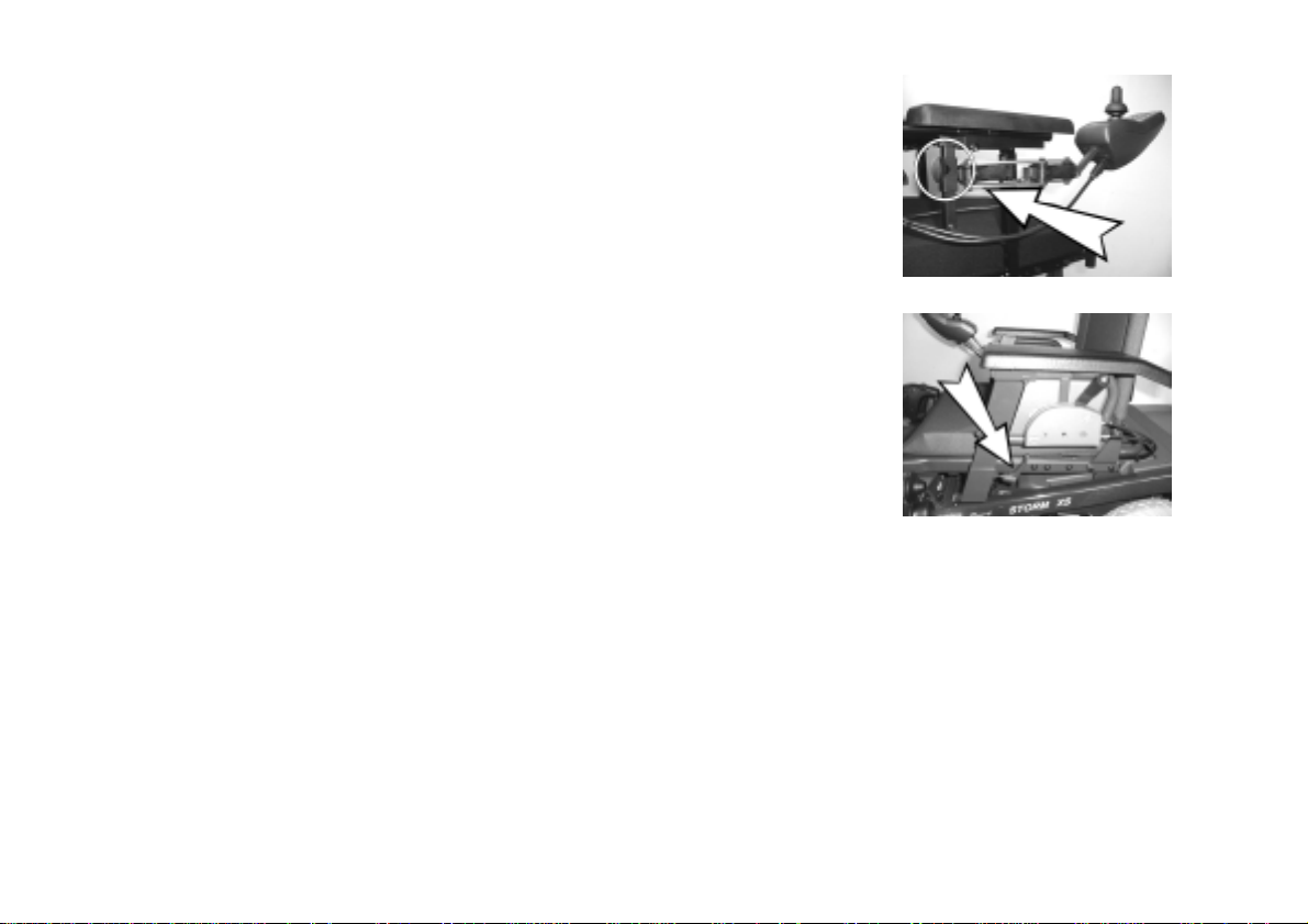
8.1.1 Adjusting the Joystick Box to length of the arm:
• Loosen the thumb screw that holds the Joystick Box by turning it
counterclockwise.
• Adjust the Joystick Box to the length of the arm by sliding it forwards or
backwards.
• Re-tighten the thumb screw that holds the Joystick Box by turning it
clockwise.
8.1.2 Swinging the Joystick Box out to the side (option):
• Swing the Joystick Box out to the side.
• Swing the Joystick Box back. It is held in it's normal position by a spring
catch.
51
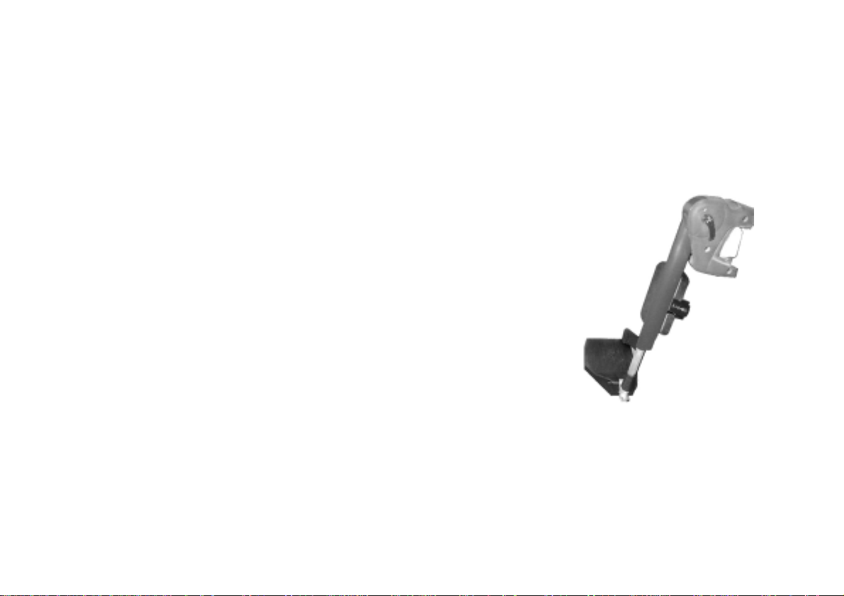
8.1.3 Adjusting the height of the Joystick Box (option):
• Loosen the thumb screw that holds the Joystick Box by turning it
counterclockwise.
• Adjust the height of the Joystick Box by sliding it upwards or downwards.
• Re-tighten the thumb screw that holds the Joystick Box by turning it
clockwise.
8.1.4 Adjusting the height of the armrests
• Loosen the clamping lever.
• Pull the armrest upwards until the desired height is reached.
• Re-tighten clamping lever again.
52

9 Seating systems
9.1 Standard and Kontur Seats
Kontur Seat
9.1.1 Adjusting the seat tilt
Manual adjustment:
• Manual adjustment:
• Loosen the knurled nut (1) and screw downwards.
• Turn the threaded adjustment sleeve (2) counterclockwise = lift the front
edge of the seat.
• Turn the threaded adjustment sleeve (2) clockwise = lower the front edge
of the seat.
• Re-tighten the knurled nut (1).
53

Electric adjustment:
The seat tilt of the wheelchair with electric actuator is adjusted using the ACS-Joystick Box. The adjustment
is infinitely variable, and can be selected in the range between -1° and +18°. If your wheelchair is equipped
with an electric lifter, then the adjustment range is between 0° and 9°.
• Switch the Joystick Box to Driving Mode "0” using the "Driving Mode Down” Button (see the description
of the Joystick Box). The Driving Mode Display automatically switches to a symbol of the seat.
• By moving the Joystick to the right or left, the different options are
displayed one after the other as symbols. Scroll through options until you
the symbol depicted at right.
• You can now individually adjust the seat tilt by moving the Joystick
forwards or backwards.
• Finally, switch the Joystick Box back to Driving Mode by pressing the "Driving Mode Up” Button.
54

9.1.2 Backrest adjustment
Manual adjustment:
• The lever for adjusting the backrest can be located either on the right or left
side behind one of the clamping levers for adjusting the armrest height.
• Pull lever upwards.
• Press backrest backwards using your own weight.
• When the backrest is in the desired position, release the lever.
55

Adjustment by metal plate with holes (available as an option for
Standard Seats)
• The angle of the backrest is determined by the metal plate with screw-
holes, which attaches the backrest to the frame.
• The angle can be changed by selecting different combinations of holes
between 0°, 5°, 10° or 15° (see drawing).
Position of the metal
plate
• Remove the screws that hold the backrest frame on both sides using a 13
mm open-end spanner.
• Select the correct holes for the desired angle using the drawing at right.
• Re-fasten the backrest frame using the hole combination selected.
NOTE:
To make it easier to re-position the screws that hold the backrest, it may be held in place by a
second person.
56
Metal plate with holes

Backrest with electric adjustment (option):
WARNING: Danger of tipping over!
• When driving, the backrest angle must never exceed 15°!
The backrest angle of the wheelchair with electric actuator is adjusted using the ACS-Joystick Box. The
adjustment is infinitely variable, and can be selected in the range between 0° and 45°.
• Switch the Joystick Box to Driving Mode "0” using the "Driving Mode Down” Button.
The Driving Mode Display automatically switches to a symbol of the seat.
• By moving the Joystick to the right or left, the different options are displayed one after
the other as symbols. Scroll through options until you the symbol depicted at right.
• You can now individually adjust the angle of the backrest by moving the Joystick
forwards or backwards.
• Finally, switch the Joystick Box back to Driving Mode by pressing the "Driving Mode
Up” Button.
57

9.1.3 Adjusting the headrest
Height adjustment:
• Loosen the clamping lever (1).
• Slide the headrest to the desired height.
• Re-tighten clamping lever (1).
Positioning the headrest:
• Loosen the clamping lever (2).
• Adjust the headrest to the desired angle.
• Re-tighten clamping lever (2).
58

9.1.4 Adjusting the height of the armrests
• Loosen the clamping lever.
• Pull the armrest upwards until the desired height is reached.
• Re-tighten clamping lever again.
9.1.5 Adjusting the height of the sideframes
• Loosen the screws using a 4 mm Allen Key.
• Adjust the sideframes to the desired position.
• Tighten the screw again.
9.1.6 Seat width adjustment:
• The clamping levers which allow adjustment of the seat width are located
under the seat.
Position of the clamping
levers
59

• Loosen the clamping lever.
• Pull the armrest frames outwards until the desired width is reached.
• Re-tighten clamping lever again.
9.1.7 Adjusting the pommel:
To position the pommel:
• Loosen the thumb screws (1 to 3)
• Adjust the pommel to the desired position.
• Re-tighten the thumb screws (1 to 3)
60

9.2 Recaro Seats
9.2.1 Recaro "N-Joy" and "Miles" (mechanically adjustable)
Backrest adjustment:
• When the hand wheel is turned forwards, the backrest is raised.
• When the hand wheel is turned backwards, the backrest is lowered.
Adjusting the height of the armrests
• Loosen one of the thumb screws depicted at right.
• Pull the armrest upwards until the desired height is reached.
• Re-tighten the thumb screw again.
61

9.2.2 Recaro Ergomed DS (electrically adjustable):
For a detailed description of the functions of the
Recaro Ergomed DS, please see the Recaro User's Manual.
By pressing the buttons, the Recaro Seat can be individually adjusted.
1. Backrest cushion 1
2. Backrest cushion 2
3. Seat height / seat tilt rear
4. Seat height / seat tilt front
5. Backrest Adjustment
62

9.3 Invacare® Ultimate and Personal Special
Seating Systems
There are two different Invacare® Special Seating Systems, the Personal and
the Ultimate versions. Both systems have ergonomically formed back and seat
elements. In addition, the Ultimate back is equipped with inflatable side and
lumbar cushions.
9.3.1 Adjusting the seat tilt
Manual adjustment:
• Manual adjustment:
• Loosen the knurled nut (1) and screw downwards.
• Turn the threaded adjustment sleeve (2) counterclockwise = lift the front
edge of the seat.
• Turn the threaded adjustment sleeve (2) clockwise = lower the front edge
of the seat.
• Re-tighten the knurled nut (1).
Electric adjustment:
• Adjustment of the seat tilt by means of an electric actuator is described in
the ACS User's Manual.
Invacare® Special
Seating System
63

9.3.2 Seat version: Personal
9.3.2.1 Adjusting the height of the back
• Loosen the screws that hold both (1) retainer plates with a Phillips
Screwdriver.
• Determine which holes in the backrest frame (2) and on the plates
correspond to the desired height.
• Re-fasten the plates using the hole combination selected.
Retainer plate
64

9.3.2.2 Adjusting the backrest angle
The angle of the backrest is determined by the pins and the slots in the plates on the
backrest frame.
• Release the securing belts (1) for the lower backrest holder (Velcro).
Plate - pins
lower slot
Lower
backrest
holder
65

• Turn the levers (1) of both holders until the cams (2) can be pulled out of
the slots on the plates.
Lower backrest holder
• Unhook the upper backrest support and reposition it in the desired slots.
• Bring the lower backrest support into the desired position.
• Turn the levers (1) of both holders until the cams (2) can be slid into the
slots on the plates.
• Slide the holder in and turn until it reaches the securing belts.
• Secure the lever using the securing belts.
66
Retainer plate
Upper backrest support
Lower backrest holder

9.3.3 Seat version: Ultimate
9.3.3.1 Adjusting the height of the back Position of the backrest
holder
• Loosen the retainer screws (1) of both upper backrest holders with a 4mm
Allen Key.
• Adjust to the desired height.
• Tighten the screws again.
Backrest holder
67

9.3.3.2 Adjusting the backrest angle
The angle of the backrest is determined by the metal plate with screw-holes,
which attaches the backrest to the frame.
The angle can be changed by selecting different combinations of holes
between 0°, 5°, 10° or 15° (see drawing).
Position of the metal
plate
• Remove the screws that hold the backrest frame on both sides using a 13
mm open-end spanner.
• Select the correct holes for the desired angle using the drawing at right.
• Re-fasten the backrest frame using the hole combination selected.
NOTE:
To make it easier to re-position the screws that hold the backrest, it may be held in place by a
second person.
68
Metal plate with holes

Fine adjustment of the backrest angle:
By turning the hand wheel, the backrest angle can be finely adjusted.
• Turn the hand wheel to the right = increase the angle
• Turn the hand wheel to the left = decrease the angle
Hand wheel
9.3.3.3 Adjusting the inflatable cushions
• Inflate the inflatable cushions to the required size using the rubber hand
pumps.
Right and left rubber hand pumps = lateral inflatable cushions
Middle rubber hand pump = lumbar cushion.
• Let air out of the lateral cushions using the release valves (1).
• Let air out of the lumbar cushion by using the release valve screw (2).
Position of the rubber
hand pumps
Letting air out
69

9.3.3.4 Removing the backrest
• Loosen the clamps on both upper backrest holders by turning them.
Upper backrest holders
70
Lower
latching
mechanism

• Pull both lower latching mechanisms and remove backrest in an upward
direction.
Refitting the backrest:
• Fit the backrest into the upper backrest holders and tighten the clamps.
• Pull the lower release mechanisms and snap the backrest into the
backrest frame.
Pull the levers
Refitting the backrest
71

10 Footrests and Legrests
The Powerchair can be equipped with various different footrests and legrests. The individual types and their
functions will be explained in this chapter.
10.1 Footrests
10.1.1 Footrest (standard)
• With Pre-Adjusted Angle
General Information
The footrest can easily be adapted to the individual needs of the user. The
angle of the footrest in relation to the seat and its length are adjustable. This
way the footrest can be individually adjusted to the angle of the seat the user's
needs.
Adjustment of the footrest can be done with corresponding tools. We
recommend that this adjustment be done by a trained Invacare® Dealer.
72

10.1.1.1 Removing the Footrest
• Release footrest by pressing button.
• Swing footrest out approximately 90°.
• Pull footrest up out of its holder.
73

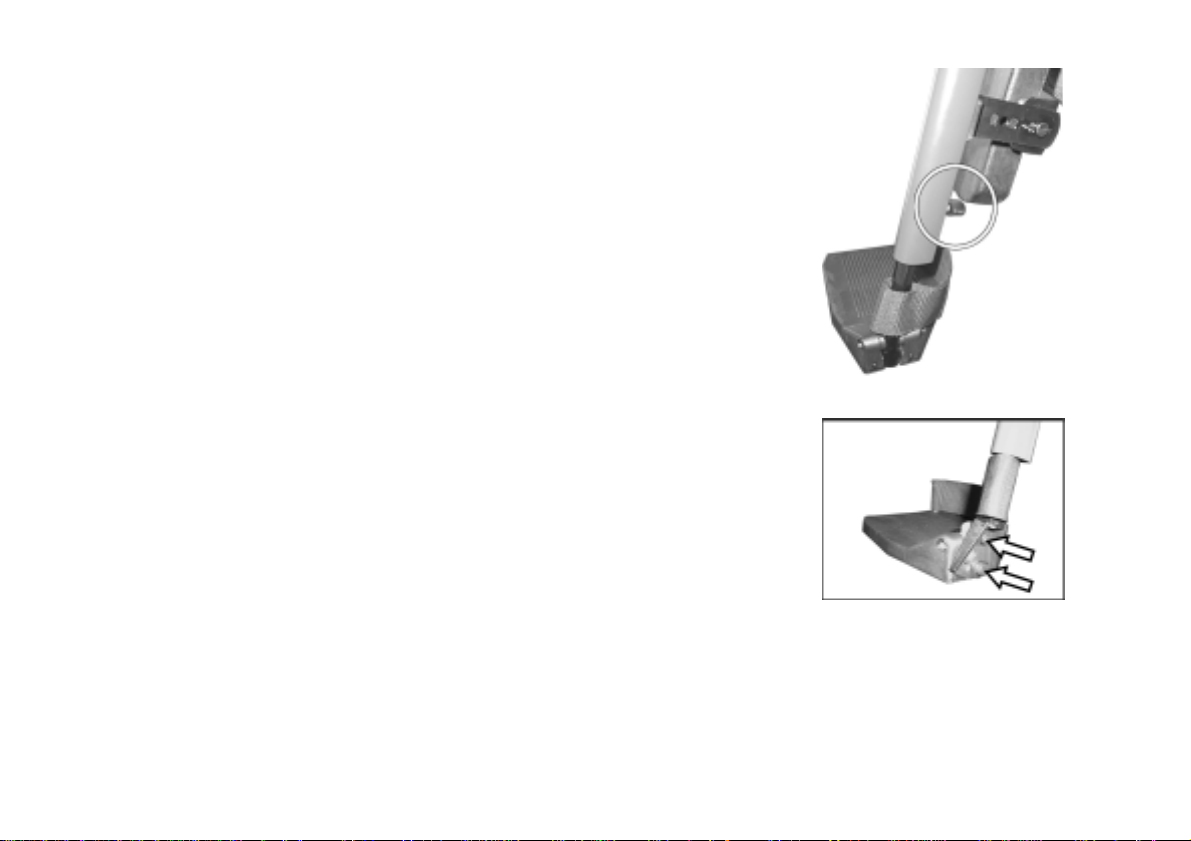
10.1.1.2 Footrest: Adjusting the Angle
Warning: Danger of Injury if footrest or legrest is incorrectly adjusted!
• Before and during each drive, always make sure there is sufficient clearance between the
legrest (or footrest) and the ground, as well as the castors!
• Loosen the screw that allows the angle to be adjusted (1).
• It the footrest still cannot be moved after loosening the screw, position a
metal pin in the hole on the side (2) and tap it lightly with a hammer. This
releases the clamping mechanism inside the footrest. If necessary, repeat
this procedure from the other side of the footrest.
• Adjust to the desired angle.
• Tighten the screw again.
74

10.1.1.3 Footrest: Adjusting the Length
• Loosen the screw which allows the length to be adjusted using a 5mm
Allen Key.
• Adjust to the desired length.
• Tighten the screw again.
10.1.1.4 Footrest: Adjusting the Angle of the Footplate (Option)
• Loosen both screws of the footplate using a 5mm Allen Key.
• Adjust to the desired angle.
• Tighten the screws again.
75
10.2 Legrests
10.2.1 Settable Legrest (Option)
• Manual Height Adjustment
• Angle Adjustment of the Legrest = 90° - 0°
• Footplate Angle Adjustable
General Information
The settable legrest can easily be adapted to the individual needs of the user.
The angle of the footrest in relation to the seat and its length are adjustable.
This way the footrest can be individually adjusted to the angle of the seat the
user's needs.
The angle and length adjustments of the settable legrest are equipped with a
quick-release mechanism.
76
10.2.1.1 Removing the Legrest
• Release footrest by pressing button.
• Swing footrest out approximately 90°.
• Pull footrest up out of its holder.
77

10.2.1.2 Settable legrest: Adjusting the Angle
Warning: Danger of Injury if footrest or legrest is incorrectly adjusted!
• Before and during each drive, always make sure there is sufficient clearance between the
• Release the quick-release (1) of the angle adjustment by pulling the lever
up.
• Adjust to the desired angle (2).
• Press the lever back down and secure the quick-release (1) by turning it
clockwise.
legrest (or footrest) and the ground, as well as the castors!
78
10.2.1.3 Settable legrest: Adjusting the Length
• Loosen the screw that allows the length to be adjusted.
• Adjust to the desired length.
• Tighten the screw again.
10.2.1.4 Settable legrest: Adjusting the Angle of the Footplate
• Loosen both screws of the footplate using a 5mm Allen Key.
• Adjust to the desired angle.
• Tighten the screws again.
79

10.2.2 Manually Adjustable Legrest
• Manual Height Adjustment
• Angle Adjustment of the Legrest = 80° - 0°
• Ergonomic Length Compensation
• Footplate Angle Adjustable
General Information
The manually height-adjustable legrest provides quick mechanical adjustment
of the angle of the legrest.
Adjustment of the length of the legrest and of the angle of the footplate can be
done with corresponding tools. We recommend that this adjustment be done
by a trained Invacare® Dealer.
80

10.2.2.1 Removing the Legrest
• Release footrest by pressing button.
• Swing footrest out approximately 90°.
• Pull footrest up out of its holder.
81

10.2.2.2 Height Adjustment for Ergonomic Length Compensation
Warning: Danger of Injury if footrest or legrest is incorrectly adjusted!
• Before and during each drive, always make sure there is sufficient clearance between the
legrest (or footrest) and the ground, as well as the castors!
Ergonomic Length Compensation of the legrest is only given if the pivot point
of the legrest (1) corresponds with that of the user's knee.
To insure this, the height of the pivot point of the legrest must be adjusted to
suit the user.
• Loosen and remove the screws (2) using a 5mm Allen Key.
• Adjust the height of the legrest, align it with the holes (3) and reposition
the screws.
• Tighten the screws (2) and test the clearance of the legrest.
NOTE:
Adjustment of the height should only be done by authorised
technicians.
82

10.2.2.3 Manually adjustable legrest: Angle Adjustment
Warning: Danger of injury by moving parts!
• Do not place fingers in the area between the upper and lower parts of the legrest!
• Adjust the legrest upward by pulling it up to the desired angle (1).
• To lower the legrest, hold it by the footplate, pull the adjustment lever on
the side (2) and slowly lower the legrest (3).
NOTE:
After letting the adjustment lever go, the legrest is locked at the desired angle.
83

10.2.2.4 Manually adjustable legrest: Adjusting the Length
• Loosen the screw which allows the length to be adjusted using a 5mm
Allen Key.
• Adjust to the desired length.
• Tighten the screw again.
10.2.2.5 Manually adjustable legrest: Adjusting the Angle of the
Footplate
• Loosen both screws of the footplate using a 5mm Allen Key.
• Adjust to the desired angle.
• Tighten the screws again.
84

10.2.3 Electrically Adjustable Legrest
• Electric Height Adjustment
• Angle Adjustment of the Legrest = 80° - 0°
• Ergonomic Length Compensation
• Footplate Angle Adjustable
General Information
The angle of the electrically elevatable legrest can the adjusted electrically.
Adjustment of the length of the legrest and of the angle of the footplate can be
done with corresponding tools. We recommend that this adjustment be done
by a trained Invacare® Dealer.
85

10.2.3.1 Removing the Legrest
• Release footrest by pressing button.
• Swing footrest out approximately 90°.
• Pull footrest up out of its holder.
86

10.2.3.2 Height Adjustment for Ergonomic Length Compensation
Warning: Danger of Injury if footrest or legrest is incorrectly adjusted!
• Before and during each drive, always make sure there is sufficient clearance between the
legrest (or footrest) and the ground, as well as the castors!
Ergonomic Length Compensation of the legrest is only given if the pivot point
of the legrest (1) corresponds with that of the user's knee.
To insure this, the height of the pivot point of the legrest must be adjusted to
suit the user.
• Loosen and remove the screws (2) using a 5mm Allen Key.
• Adjust the height of the legrest, align it with the holes (3) and reposition
the screws.
• Tighten the screws (2) and test the clearance of the legrest.
NOTE:
Adjustment of the height should only be done by authorised
technicians.
87

10.2.3.3 Electrically adjustable legrest: Angle Adjustment
Warning: Danger of injury by moving parts!
• Do not place fingers in the area between the upper and lower parts of the legrest!
The electric actuator, which adjusts the angle, is controlled using the
remote.
• Select Menu Point "0” using the "Driving Mode Shift Down” Button on the
remote.
• The symbol changes automatically from "0” to a symbol of the seat.
• By moving the joystick to the left or to the right, scroll through options of
the menu until you see one of the symbols shown at the right flashing on
the display.
• The flashing symbol shows which legrest can be adjusted.
• By pushing the joystick forward you move the selected legrest
• upwards.
• By pulling the joystick back you move the selected legrest downwards.
Adjust left legrest
Adjust right legrest
88

10.2.3.4 Legrest: Adjusting the Length
• Loosen the screw which allows the length to be adjusted using a 10 mm
open-end spanner.
• Adjust to the desired length.
• Tighten the screw again.
10.2.3.5 Legrest: Adjusting the Angle of the Footplate
• Loosen both screws of the footplate using a 5mm Allen Key.
• Adjust to the desired angle.
• Tighten the screws again.
89

10.3 Width Adjustment of the Legrests (Option):
• The screws that allow adjustment of the width are located under the seat.
Position of the clamping
lever
NOTE:
The lights must not be obscured by the legrests.
If necessary, they must be positioned farther toward the outside.
To do this, use the different holes of the mounting plates.
• Loosen the screws (1) using a 4 mm Allen Key.
• Pull the legrest mounting brackets (2) outwards until the desired width is
reached.
• Tighten the screws again.
90

11 Lifter (option)
The seat-lifting system for the STORM, called the STORM Lifter, is a useful
option that provides the active user with more flexibility by lifting the seat up to
30 cm. It is available in two versions: the one allows a permanent adjustment
of the seat tilt by means of adjustment screws, the other is equipped with an
electric actuator for this purpose.
NOTE:
As soon as the lifter is raised, the STORM moves at a reduced speed.
To increase your speed again, lower the lifter completely. For a
detailed description, see the part on automatic speed reduction
below.
In all other respects the STORM Lifter model is the same as other
models of the STORM Series.
91

11.1 Adjusting the seat tilt on a STORM with a
Lifter Module
Manual adjustment of the seat tilt of the Standard Seat or the Kontur
Seat:
• During adjustment no one may be seated in the chair.
• Remove the screws that allow adjustment of the seat tilt, which are in the
front under the seat.
• Adjust to the desired seat tilt.
• Reposition the screws and make sure that they are tightened sufficiently.
To adjust a Recaro Seat see Chap. 11.2 of this manual.
92

11.2 Adjustment of the electric Lifter Module:
The electric actuator which adjusts the height is controlled using the
remote.
• Select Menu Point "0” using the "Driving Mode Shift Down” Button on the
remote. The symbol changes automatically from "0” to a symbol of the
seat.
• By moving the joystick to the left or to the right, scroll through the options of
the menu until you see the symbol shown at the right flashing on the
display:
• The lifter is activated.
• By pushing the joystick forward you move the lifter upwards.
• By pulling the joystick backward you move the lifter back down.
93

11.3 Automatic speed reduction:
The STORM Lifter has a safety function, which automatically reduces the speed of the wheelchair as soon
as the lifter is raised. In this mode the Status Display on the Joystick Box flashes two times repeatedly.
The speed of the STORM is reduced as follows:
• Lifter down = 100% of wheelchair's maximum power.
• Lifter up = 30% of wheelchair's maximum power.
• To increase your speed again, lower the lifter completely.
11.4 Technical Specifications of the Lifter Module:
• Seat can lifted up to approx. 30 cm.
• Maximum load (payload)100 kg.
• Adjustment of seat tilt (manual or electric) between -2° and +9° in relation to horizontal.
• Weight of the Lifter Module including electric actuator = approx. 14.5kg
• The Lifter Module can be retrofitted.
Retrofitting can be done at the factory or by a qualified dealer.
94

12 Electrical System
12.1 Electronics Protection System
The vehicle's electronics are equipped with an overload-protection system.
If the motors are put under considerable strain for a longer period of time (for example, when
driving up a steep hill) and especially when the ambient temperature is high, then the electronic
system could overheat. In this case the vehicle's power is reduced gradually until it finally comes to
a halt. The Status Display shows a corresponding error code. By switching the power supply off
and back on again, the error code is cancelled and the electronics are switched back on. It will take
approximately five minutes until the electronics have cooled down enough for the motors to restore
full power again.
When the motors are stalled by an insurmountable obstacle, such as a high kerb, and the vehicle
driver allows the motors to strain against this hindrance for more than 20 seconds without moving,
then the electronics will automatically switch off to prevent the motors from being damaged. The
Status Display shows a corresponding error code. By switching off and back on again, the error
code is cancelled and the electronics are switched back on.
95

12.2 Batteries
12.2.1 What you need to know about batteries
Power is supplied by two 12V gel batteries. The batteries are maintenance-free and only need
regular charging.
New batteries should always be fully charged once before their first use. New batteries will be at
their full capacity after having run through approx. 10 - 20 charging cycles. How fast the batteries
will be discharged will depend on many circumstances, such as ambient temperature, condition of
the surface of the road, tyre pressure, weight of the driver, way of driving and utilisation of lighting,
etc.
96

NOTE
Gel batteries are not hazardous goods. This classification is based on the German GGVS
Hazardous Goods Road Transport Ordinances, and the IATA/DGR Hazardous Goods Rail
Transport / Air Transport Ordinances. Gel batteries may be transported without restrictions,
whether by road, rail or by air. Individual transport companies have, however, guidelines which can
possibly restrict or forbid certain transport procedures. Please ask the transport company regarding
each individual case.
Pay attention to the Battery Charge Indicator! Make sure to charge the batteries when the Battery
Charge Indicator shows that battery charge is low. We recommend charging the batteries after
each trip, as well as each night over night. Depending on the level of discharge, it can take up to 12
hours until the batteries are fully charged again.
Protect your charger from sources of heat such as heaters and direct sunlight. If the battery
charger overheats, charging current will be reduced and the charging process delayed.
To avoid damaging the batteries, never allow them to be fully discharged. Do not drive on heavily
discharged batteries if it is not absolutely necessary, as this will strain the batteries unduly and
shorten their life expectancy.
In case your vehicle is not used for a longer period of time, then the batteries must be charged at
least once a month to maintain a full charge. Alternatively, the vehicle can stay connected to the
charger. The batteries cannot be overcharged with the specified charger.
Please use only charging devices in Class 2. This class of chargers may be left unattended during
charging. All charging devices which are supplied by Invacare® and comply with these
requirements.
97

12.2.2 Charging the batteries
• Make sure you read and understand the battery charger's User's Manual, if supplied, as well as
the safety notes on the front and rear panels of the charger!
WARNING:
Danger of explosion and destruction of batteries if the wrong battery charger is used!
• Only ever use the battery charger supplied with your vehicle, or a charger that has been
approved by Invacare®!
Danger of electric shock and damage to the battery charger if it is allowed to get wet!
• Protect the battery charger from water!
• Always charge in a dry environment!
Danger of short circuit and electric shock if the battery charger has been damaged!
• Do not use the battery charger if it has been dropped or damaged!
Danger of fire and electric shock if a damaged extension cable is used!
• Only ever use an extension cable if it is absolutely necessary! In case you must use one,
make sure it is in good condition!
98

Charging the batteries
• Switch off the wheelchair at the Joystick Box.
• Connect the battery charger to the Joystick Box - the charging
socket is located on the bottom of the Joystick Box.
• Connect battery charger to the mains outlet and switch on if
necessary.
• After charging is complete, first disconnect the battery charger
from the mains supply, then disconnect from the Joystick Box.
Charging Socket of the
Joystick Box
99

12.2.3 Removing and fitting batteries
WARNING:
Danger of injury if the batteries are not handled correctly during assembly and
maintenance work!
• New batteries should be installed by authorised technicians!
• Observe the warnings on the batteries!
• Take into account the heavy weight of the batteries!
• Only ever use the battery type defined in the technical specifications!
Danger of fire and burns if battery terminals are short-circuited!
• DO NOT short-circuit battery terminals with a tool!
WARNING:
Corrosion and burns from acid leakage if batteries are damaged!
• Remove clothes that have been soiled by acid immediately!
After contact with skin:
• Immediately wash affected area with lots of water!
After contact with eyes:
• Immediately rinse eyes under running water for several minutes; consult a physician!
100
 Loading...