

Page 1
Lift-Out Chair
Assembly, Installation and Operating Instructions
NAME MODEL NO. COLOR
Murphy LC11 Beige
LC12 Ocean Blue
LC13 Mauve
Fairview LC21-1 Light Brown
LC22-1 Blue
LC23-1 Burgundy
LC24-1 Green
Stanford LC31 Toast
LC32 Blue
LC33 Mauve
LC34 Green
Woodbriar LC41 Beige
LC42 Blue
LC43 Mauve
LC44 Green
Manchester LC51-1 Chestnut Brown
LC52-1 Midnight Blue
LC53-1 Burgundy
LC54-1 Evergreen
LC55 Beige
LC56 Black
LC57 Burgundy
LC58 Hunter Green
Jamestown LC61 Navy
LC62 Royal Blue
LC63 Burgundy
LC64 Hunter Green
New Yorker LC75 Beige
LC76 Green
LC77 Burgundy
LC78 Black
BellAire LC85 Cocoa Brown
LC86 Deep Blue
LC87 Mahogany
LC88 Forest Green
TECHNICAL SPECIFICATIONS
Voltage: 115 VAC
Frequency: 60 Hz
Power: 130 Watts
Duty Cycle: Intermittent duty
2 min ON/18 min OFF
Weight Capacity: 350 lbs (160 kg)
SAFETY SUMMARY
The following recommendations are made for the safe
installation and proper operation of the Invacare
Lift-Out Chair:
GENERAL WARNINGS
DO NOT operate this equipment without
first reading and understanding this instruction sheet. If you are unable to understand
the Warnings, Cautions, and Instructions,
contact a healthcare professional, dealer
or technical personnel if applicable before attempting to use this equipment - otherwise injury or damage may result.
After ANY adjustments, repair or service
and BEFORE use, make sure all attaching
hardware is tightened securely.
DO NOT move the chair when occupied.
DO NOT sit on the ottoman. It is not de-
signed as a seating area.
DO NOT stand on the ottoman when en-
tering or exiting the chair. The chair WILL
tip and bodily injury may occur.
Always leave chair in an upright (closed)
position when not in use. DO NOT leave
the chair in the elevated position.
DO NOT operate the seat lift movement
of your chair with anyone seated on your
lap or on the arms of the lift chair/power
recliner.
The hand held pendant control is designed
to be operated by the occupant only.
DO NOT allow children to play on or operate the chair. The ottoman folds down on
closing; a child could sustain injury. Keep
hands and feet clear of ottoman and scissors mechanism.
Ensure that legs and arms do not come in
contact with moving parts of the chair. If it
is necessary to retrieve items that may have
fallen under the chair, make certain the
chair is unplugged before proceeding.
When sitting on elevated chair, center
your weight in the chair.
NOTE: Inspect the chair for any damage, i.e., nicks, tears
or frame damage. Check pendant and power cord for breakage or damage. If any of these conditions exist, do NOT
attempt to use the chair. Contact distributor for further
instruction.
1
Page 2
SAFETY SUMMARY (CONTINUED)
GENERAL WARNINGS
Exercise extreme caution if there is a
power failure when chair is in fully reclined
position. User should be aware that when
the power fails the lift out chair will not
operate and is advised to find assistance
when exiting chair.
WEIGHT LIMITATION
The Lift-Out Chair can NOT be used by indi-
viduals weighing more than 350 lbs (160 kg.)
CAUTION (CONTINUED)
DO NOT operate the chair more than two
(2) minutes every twenty (20) minutes (2 minutes ON/ 18 minutes OFF). If the chair is operated excessively, the protective thermal
overload switch will shut off the motor. If
this occurs, it may take several hours for
the motor to cool down and reset the thermal overload switch. The chair will operate again once the motor has cooled off.
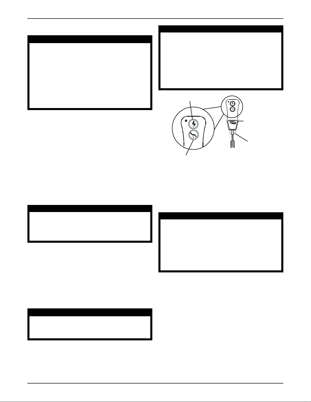
Lift Button
POSITIONING THE LIFT-OUT
CHAIR
1. Make certain there is adequate room to operate your
chair. With the chair in the closed (upright) position,
there must be 18-inches (45 cm) of clearance between
the top of the chair back and the wall. Nothing should
obstruct the back or the ottoman as the chair reclines.
2. Remove the cardboard corner pads (used for shipping) from the bottom of the chair before use. Ensure
all staples holding the cardboard corner pads are removed or not sticking up from the wood frame. This
will alleviate any rubbing with the lift mechanism.
CAUTION
All staples holding the cardboard corner
pads MUST be removed or not sticking up
from the wood frame-otherwise injury or
damage may result.
OPERATION (FIGURE 1)
NOTE: Refer to the GENERAL WARNINGS in the
SAFETY SUMMARY of this Instruction Sheet.
Pendant Hand
Control
Lockout Key
(Canadian)
Recline Button
FIGURE 1 - OPERATION
Raising/Lowering The Chair To The
Standing Position
NOTE: Refer to the GENERAL WARNINGS in the
SAFETY SUMMARY of this Instruction Sheet.
WARNING
When sitting on the chair in the elevated
position, center your weight in the chair.
This chair is designed to stop automatically at its fully raised height. If you are a
shorter person, raising the chair beyond
your normal standing height may cause
you to slide toward the front of the seat
or possibly fall from the chair.
NOTE: The chair's lift-out and power recliner is operated
by a hand held pendant control. Depressing the lift button
will raise the chair to a standing position. Depressing the
recline button will lower the chair to a flat, reclined position.
The chair will stop moving when the button is released.
CAUTION
DO NOT operate the chair in the recline
mode without someone in the chair. This
will cause unnecessary strain on the motor.
1. Perform one (1) of the following.
A. To raise the chair to the standing position, depress
and hold the Lift Button until the chair is at the
most comfortable position to enter or exit.
B. To lower the chair back to the seated position,
depress and hold the Recline Button.
Reclining The Chair
1. Perform one (1) of the following.
A. To recline the chair, depress and hold the Re-
cline Button until the chair has reclined to the
desired position.
B. To raise the chair back to the seated position,
depress and hold the Lift Button.
2
Page 3

REPOSITIONING THE PENDANT
HAND CONTROL (FIGURE 2)
NOTE: Refer to the GENERAL WARNINGS in the
SAFETY SUMMARY of this Instruction Sheet.
NOTE: This procedure should only be performed by
a qualified technician.
1. Place the chair into the seated position.
2. Unplug the motor power cord from the wall.
3. Remove the screws and cable clamps securing the
pendant cable to the underside of the armrest.
4. Remove the screw and cable clamp securing the
pendant cable to the back of the chair.
5. Roll the chair forward onto the ottoman and the front
of the seat back.
6. Plug the motor power cord into the wall.
7. Press the pendant button in the recline direction slightly
to produce sufficient slack in the flap of fabric to thread
the pendant in through the flap.
8. Press the pendant button in the lift direction until the lift
mechanism is fully raised.
9. Unplug the chair power cord from the wall.
10. Remove the screw and cable clamp from the side of
the rear corner of the chair.
11. Remove the screw and cable clamp from the middle
of the side of the chair.
12. Remove the cable tie securing the pendant cable to
the lift frame.
NOTE: Do not remove the cable tie securing the pendant cable to the motor.
13. Pull the pendant cable to a spot 7-1/2-inches from the
inside of the rear 1-inch square frame tube as shown
in DET AIL "A" of FIGURE 2.
14. Secure the pendant cable to the lift frame with a cable tie at
the point closest to the cable as shown in DETAIL "B"
of FIGURE 2.
NOTE: There should be minimal slack in the cable
between the motor and lift frame.
15. Secure the pendant cable to the middle of the side of
the chair with a screw and cable clamp. As shown in
DET AIL "B" of FIGURE 2.
NOTE: There should be minimal slack in the cable
between the lift frame and cable clamp.
16. Pull the pendant cable tight along the side of the chair
to the rear corner of the chair.
17. Secure the pendant cable to the side of the rear corner with no slack in the cable. As shown in DET AIL
"B" of FIGURE 2.
18. Plug the chair power cord into the wall.
WARNING
DO NOT let the power cord get pinched,
cut or trapped by the lift frame. Otherwise injury or damage may result.
19. Press the pendant button in the recline direction until
the lift mechanism returns to the seating position and
just makes contact with the wood chair frame.
WARNING
DO NOT let the pendant cable get
pinched, cut or trapped by the lift frame.
Otherwise injury or damage may result.
20. Press the pendant button in the recline direction to produce sufficient slack in the rear flap of fabric to
thread the pendant back out through the flap.
21. Unplug the chair power cord from the wall.
22. Return the chair back onto all four (4) feet.
23. Pull the pendant cable tight and secure the pendant cable
to the rear of the chair with a screw and cable clamp.
24. Perform one (1) of the following:
A. Murphy, Fairview, and Woodbriar models-
proceed to STEP 25.
B. Stanford, Bellaire, Manchester, and
Jamestown models - tightly pull the pendant
cable to the bend in the armrest. Secure the
pendant cable under the bend in the armrest
with a screw and cable clamp.
C. New Yorker model - tightly pull the pendant cable
to the back end of the armrest. Secure the pendant cable under the back end of the armrest with
a screw and cable clamp.
25. Secure the pendant cable to the outer side of
the chair immediately under the armrest half way between the front of the armrest and the seat back
according to following.
A. Murphy, Fairview, Stanford models - the screw
must be placed vertically up into the underside of the
armrest as shown in FIGURE 2.
B. Woodbriar model - the screw must be placed
vertically down into the frame of the chair as shown
in FIGURE 2.
C. New Yorker , Bellaire, Manchester, Jamestown
models - the screw must be placed horizontally
into the side of the chair as shown in FIGURE 2.
NOTE: Pull the pendant cable tightly to minimize
slack when securing the cable clamp.
NOTE: Be sure to drive the screws into solid wood,
away from edges.
3
Page 4

DETAIL “A”
Cable Clamp and
Screw (As Close to
Corner as Possible)
DETAIL "B"
Cable Clamps and Screws
Motor
(Do Not Remove)
Cable Clamp and Screw (7-1/2-inches from the
Inside of the Rear 1-inch Square Frame Tube)
MURPHY, FAIRVIEW
STANFORD, NEW YORKER,
BELLAIRE, MANCHESTER,
Armrest
Cable Tie
JAMESTOWN
Armrest
Motor
Cable
Clamp
Cable Ties
WOODBRAIR
Armrest
Pendant Cord
Cable Clamps
and Screws
FIGURE 2 - REPOSITIONING THE PENDANT HAND CONTROL
18 to 21-
inches
Pendant Cord
Cable Clamps
and Screws
18 to 21-
inches
Pendant Cord
Cable Clamps
and Screws
18 to 21-
inches
4
Page 5

GENERAL MAINTENANCE
CLEANING INSTRUCTIONS
NOTE: Refer to the GENERAL WARNINGS in the
SAFETY SUMMARY of this Instruction Sheet.
WARNING
Before any maintenance is attempted, unplug the Lift Chair from the electrical outlet.
Otherwise injury or damage may result.
NOTE: Before lubricating and cleaning your chair, be sure
to place a paper or cloth under the chair.
NOTE: The lift out chair uses a completely sealed gearbox motor, and no lubrication is necessary. Depending on
chair usage, there may be a need to perform maintenance
on the lift mechanism pivot points. This needs to be done
approximately every three (3) years. The recommended
lubricant is a general purpose wheel bearing grease.
Lubrication Points (FIGURE 3)
Note: If the motor does not operate, contact Invacare
at the numbers on the back page.
1. Ensure that the plug is connected to an operating electrical outlet, and ensure that the pendant cord is
plugged into the motor socket.
2. Raise the chair to the highest position to access the
clevis pins.
Fabric Cleaning
UPHOLSTERY
Clean only with water-based shampoo or foam upholstery
cleaner.
CAUTION
DO NOT over-wet or saturate the fabric with
liquid. DO NOT use solvents to spot or clean.
l Pile fabrics may require brushing to restore ap-
pearance.
Naugahyde®
For best results, remove staining immediately. The
longer the staining is allowed to set the more difficult the stain is to remove. Blot all excess staining
residues. Always use a clean soft damp cloth when
utilizing the following cleaning methods.
For Light Soiling:
l A solution of 10% household liquid dish soap with
warm water applied with a soft damp cloth will remove most soiling.
l If necessary, use a solution of liquid cleanser and water
applied with a soft bristle brush. Wipe away the residue with a water-dampened cloth.
3. Unplug the chair.
4. Roll the chair forward onto the ottoman and the front
of the seat back.
5. Perform the following to one (1) clevis pin one at a
time (12 in all) as in FIGURE 3 - LUBRICA TION
POINTS in this INSTRUCTION SHEET:
A. Remove hitch pin securing clevis pin to the frame.
B. Remove clevis pin.
C. Apply small amount of wheel bearing grease to
the clevis pin.
D. Reverse STEPS A-B. to install clevis pin.
6. Repeat STEP 5 on remaining clevis pins.
7. Repeat STEPS 1-4 to roll the lift out chair back
into the upright position.
NOTE: If you are unable to perform regular maintenance
to this chair or have any questions regarding this product,
contact Invacare at the numbers on the back page.
For More Difficult Stains:
l Dampen a soft white cloth with a solution of house-
hold bleach (sodium hypochlorite); 1 part bleach, 4
parts water.
l Rub gently
l Rinse with a water-dampened cloth to remove bleach
concentration.
l If necessary , allow a 1:4 diluted bleach solution to
puddle on the affected area of apply with a solution
soaked cloth for approximately 30 minutes. Rinse with
a water-dampened cloth to remove any remaining
bleach concentration.
CAUTION
Try this method on an inconspicuous spot
before using it on the original stain/soiling.
Naugahyde is a registered trade mark of Uniroyal
5
Page 6

Please Review Carefully
Motor and Pendant Cleaning
Should you choose other cleaning methods or other cleaning agents, carefully try them in an inconspicuous area to
determine potential damage to the material. Never use
harsh solvents or cleaners intended for industrial applications. To clean stained or soiled areas, a soft white cloth is
recommended. Avoid use of paper towels.
Stains such as lipstick, crayon, felt tip pens, ballpoint pen,
certain dyed suntan lotions or mustard, etc. must be
cleaned immediately. The longer these and other similar
harsh/permanent stains are exposed to the vinyl surface,
the more difficult the vinyl will be to clean. In some cases,
removal of certain stains is impossible.
WARNING
Cleaning products may be harmful/irritating to your skin, eyes, etc. Use protective
gloves and eye protection. Do not inhale
or swallow any cleaning product. Protect
surrounding area/clothing from exposure.
Use in a well-ventilated area. Follow all
product manufacturers warning(s).
Unplug the chair from the wall before cleaning the motor
or pendant. The motor and pendant may be cleaned with
a damp cloth or sponge.
WARNING
DO NOT pour or spray liquids onto the motor. Otherwise injury or damage may
result.
l Cleaning agents should be free of acids or salt
water.
l Dry the motor and pendant thoroughly after clean-
ing before returning the chair to service.
6
Page 7

PARTS LIST
ITEM
1 Glide
2 Tube Closure
3 Screw
4 Cable Clamp
5 Hex Head Serrated Flange Screw
6 Twinfast Wood Screw
7 Plug Button
8 Hitch Pin
9 Clevis Pin
10 Cable Tie
11 Pan Head Screw
12 Nut, Self Locking
13 Transformer
14 Motor
15 Pendant
16 Lift Frame Assembly
17 Lockout key (Canadian)
18 Screw
19 Cable Clamp
20 Bushing
DESCRIPTION
3
4
10
8
14
19
18
15
Clevis Pin
9
17
(Lubricate)
Clevis Pin
(Lubricate)
16
7
Clevis Pin Lubrication
Points (Repeat Procedure
for opposite side.)
8
9
10
11
12
13
Clevis Pin Lubrication Points
(Repeat Procedure for
opposite side.)
5
2
7
20
1
6
FIGURE 3 - LUBRICATION POINTS
7
Page 8

LIMITED WARRANTY
PLEASE NOTE: THE WARRANTY BELOW HAS BEEN DRAFTED TO COMPLY WITH FEDERAL
LAW APPLICABLE TO PRODUCTS MANUFACTURED AFTER JULY 4, 1975.
This warranty is extended only to the original purchaser/user of our products.
This warranty gives you specific legal rights and you may also have other legal rights which vary
from state to state.
Invacare warrants electrical and mechanical components for a period of three (3) years from the
date of purchase. Upholstery fabric is warranted for a period of three (3) years from date of
purchase. If within such warranty period any such product shall be proven to be defective, such
product shall be repaired or replaced, at Invacare’s option. This warranty does not include any
labor or shipping charges incurred in replacement part installation or repair of any such product.
Invacare’s sole obligation and your exclusive remedy under this warranty shall be limited to such
repair and/or replacement.
For warranty service, please contact the dealer from whom you purchased your Invacare product. In the event you do not receive satisfactory warranty service, please write directly to Invacare at the address located at the bottom of this page, provide dealers name, address, date of
purchase, indicate nature of the defect and, if the product is serialized, indicate the serial number. Do not return products to our factory without our prior consent.
LIMITATIONS AND EXCLUSIONS: THE FORGOING WARRANTY SHALL NOT APPLY TO SERIAL NUMBERED PRODUCTS IF THE SERIAL NUMBER HAS BEEN REMOVED OR DEFACED, PRODUCTS SUBJECTED TO NEGLIGENCE, ACCIDENT, IMPROPER OPERATION, MAINTENANCE OR STORAGE, COMMERCIAL OR INSTITUTIONAL USE, PRODUCTS MODIFIED WITHOUT INVACARE’S EXPRESS WRITTEN
CONSENT INCLUDING, BUT NOT LIMITED TO, MODIFICATION THROUGH THE USE OF UNAUTHORIZED PARTS OR ATTACHMENTS; PRODUCTS DAMAGED BY REASON OF REPAIRS MADE TO ANY
COMPONENT WITHOUT THE SPECIFIC CONSENT OF INVACARE, OR TO A PRODUCT DAMAGED BY
CIRCUMSTANCES BEYOND INVACARE’S CONTROL, AND SUCH EVALUATION WILL BE SOLELY DETERMINED BY INVACARE. THE WARRANTY SHALL NOT APPLY TO PROBLEMS ARISING FROM NORMAL WEAR OR FAILURE TO ADHERE TO THESE INSTRUCTIONS.
THE FOREGOING WARRANTY IS EXCLUSIVE AND IN LIEU OF ALL OTHER EXPRESS WARRANTIES.
IMPLIED WARRANTIES, IF ANY, INCLUDING THE IMPLIED WARRANTIES OF MERCHANTABILITY AND
FITNESS FOR A PARTICULAR PURPOSE, SHALL NOT EXTEND BEYOND THE DURATION OF THE
EXPRESS WARRANTY PROVIDED HEREIN AND THE REMEDY FOR VIOLATIONS OF ANY IMPLIED
WARRANTY SHALL BE LIMITED T O REPAIR OR REPLACEMENT OF THE DEFECTIVE PRODUCT PURSUANT TO THE TERMS CONTAINED HEREIN. INVACARE SHALL NOT BE LIABLE FOR ANY CONSEQUENTIAL OR INCIDENTAL DAMAGES WHATSOEVER. SOME STATES DO NOT ALLOW THE EXCLUSION OR LIMIT A TION OF INCIDENTAL OR CONSEQUENTIAL DAMAGE, OR LIMITATION ON HOW LONG
AN IMPLIED W ARRANTY LASTS, SO THE ABOVE EXCLUSIONS AND LIMIT A TIONS MA Y NOT APPLY TO
YOU.
THIS WARRANTY SHALL BE EXTENDED TO COMPLY WITH STATE/PROVINCIAL LAWS AND
REQUIREMENTS.
Invacare Corporation www.invacare.com
USA Canada
One Invacare Way 5970 Chedworth Way Invacare is a registered trademark of Invacare Corporation.
Elyria, Ohio USA Mississauga, Ontario ©
44036-2125 L5R 3T9, Canada
800-333-6900 905-890-8838 Form No. 93-58 Part No. 53000M565 Rev I (1) 2/01
2001 Invacare Corporation
 Loading...