

PROCEDURE
10
FAN
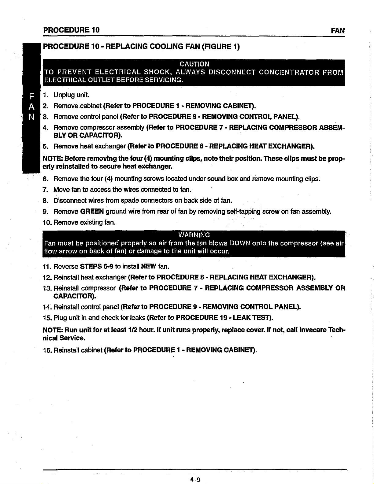
PROCEDURE
TO
ELECTRICAL
Unplug
>
"Τι
1
Ζ
Remove
Remove
op
Remove
BLY
5.
Remove
NOTE:
erly
6.
Remove
7.
Move
8,
Disconnect
9.
Remove
10.
Remove
10
PREVENT
OUTLET
unit.
cabinet
control
compressor
OR
CAPACITOR).
heat
Before
reinstalled
removing
the
fan
to
wires
GREEN
existing
to
four
access
REPLACING
-
ELECTRICAL
BEFORE
(Refer
panel
exchanger
secure
(4)
from
fan.
to
(Refer
assembly
the
heat
mounting
the
wires
spade
ground
COOLING
SHOCK,
SERVICING,
PROCEDURE
to
PROCEDURE
(Refer
(Refer
wire
to
four
(4)
mounting
exchanger.
screws
connected
connectors
from
CAUTION
ALWAYS
1 -
to
PROCEDURE
PROCEDURE
located
to
fan.
on
back
rear
of
fan
(FIGURE
FAN
DISCONNECT
REMOVING
9 - REMOVING
8 - REPLACING
clips,
note
under
by
sound
side
of
removing
1)
CABINET).
CONTROL
7 - REPLACING
HEAT
their
position.
box and
fan.
self-tapping
remove
CONCENTRATOR
PANEL).
COMPRESSOR
EXCHANGER).
These
screw
clips
mounting
on
fan
FROM
ASSEM-
must
be
prop-
clips.
assembly.
Fan
must
be
flow
arrow
11.
Reverse
12.
Reinstail
13.
Reinstall
on
STEPS
heat
compressor
CAPACITOR).
14.
Reinstall
15.
Plug
NOTE:
nical
Service.
16.
Reinstall
unit
Run
contro!
in
unit
cabinet
positioned
back
of
fan)
6-9
exchanger
panel
and
check
for
at
least
(Refer
properly
or
damage
to
install
(Refer
(Refer
(Refer
for
leaks
1/2
to
PROCEDURE
WARNING
so
air
from
to
the
NEW
fan.
to
PROCEDURE
to
PROCEDURE 7 -
to
PROCEDURE
(Refer
hour.
If
to
PROCEDURE
unit
runs
1 -
the
fan
unit
will
8 - REPLACING
REPLACING
9 - REMOVING
properly,
REMOVING
blows
occur.
19 - LEAK
replace
CABINET).
DOWN
onto
HEAT
COMPRESSOR
CONTROL
TEST).
cover.
the
compressor
EXCHANGER).
ASSEMBLY
PANEL).
If
not,
call
Invacare
(see
Tech-
air
OR
4-9
FAN
PROCEDURE
10
PROCEDURE
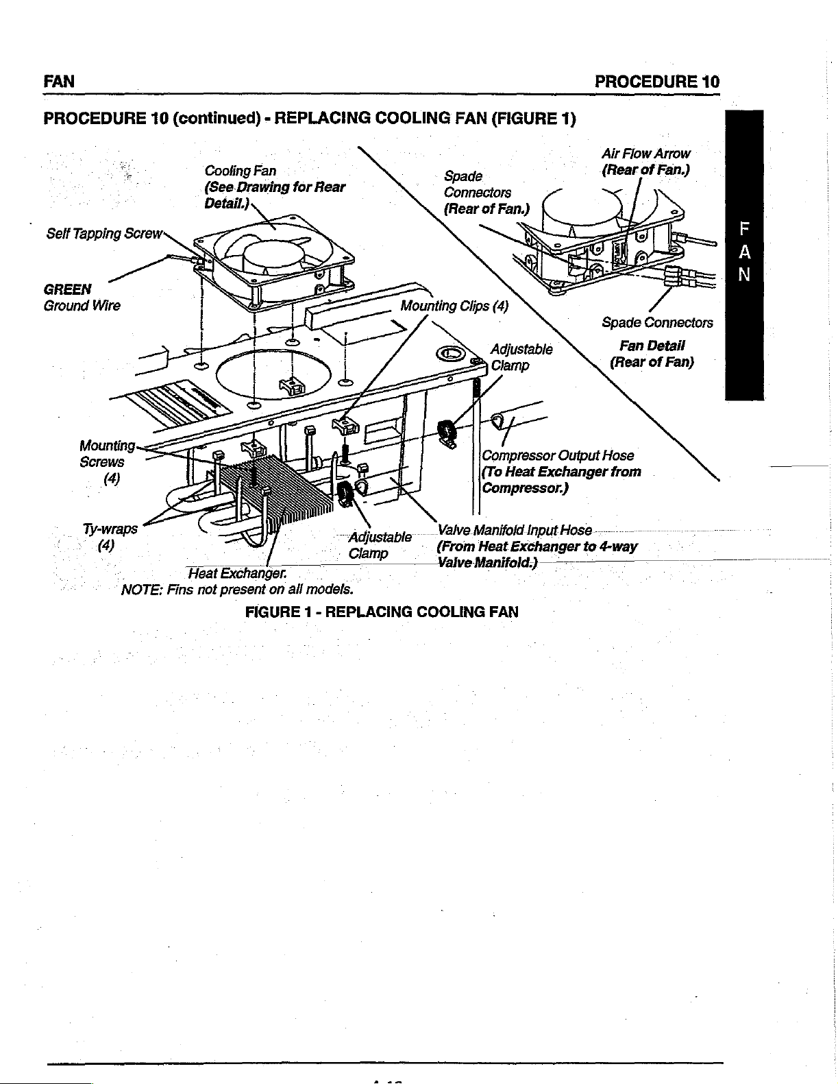
GREEN
Ground
Wire
10
(continued) - REPLACING
Cooling
(See.Drawing
Detail.)
Fan
for
Rear
COOLING
FAN
(FIGURE
Spade
Connectors
(Rear
of
Fan.)
Adjustable
=
Clamp
Compressor
(To
Heat
Compressor.)
1)
Output
Exchanger
Air
Flow
(Rear
Spade
Fan
(Rear
Hose
from
Arrow
of
Fan.)
Connectors
Detail
of
Fan)
2pm
Ty-wraps
“4
.
NOTE:
DA
Heat
Fins
Exchanger.
not
present
on
FIGURE
all
models.
1 -
~
,
Cum
一
REPLACING
Valve
>
(From
—
ValveManifold)
COOLING
Manifold
Heat
Input
Exchanger
FAN
Hose
to
4-way
PROCEDURE
11
P.C.
BOARD
REPLACEMENT
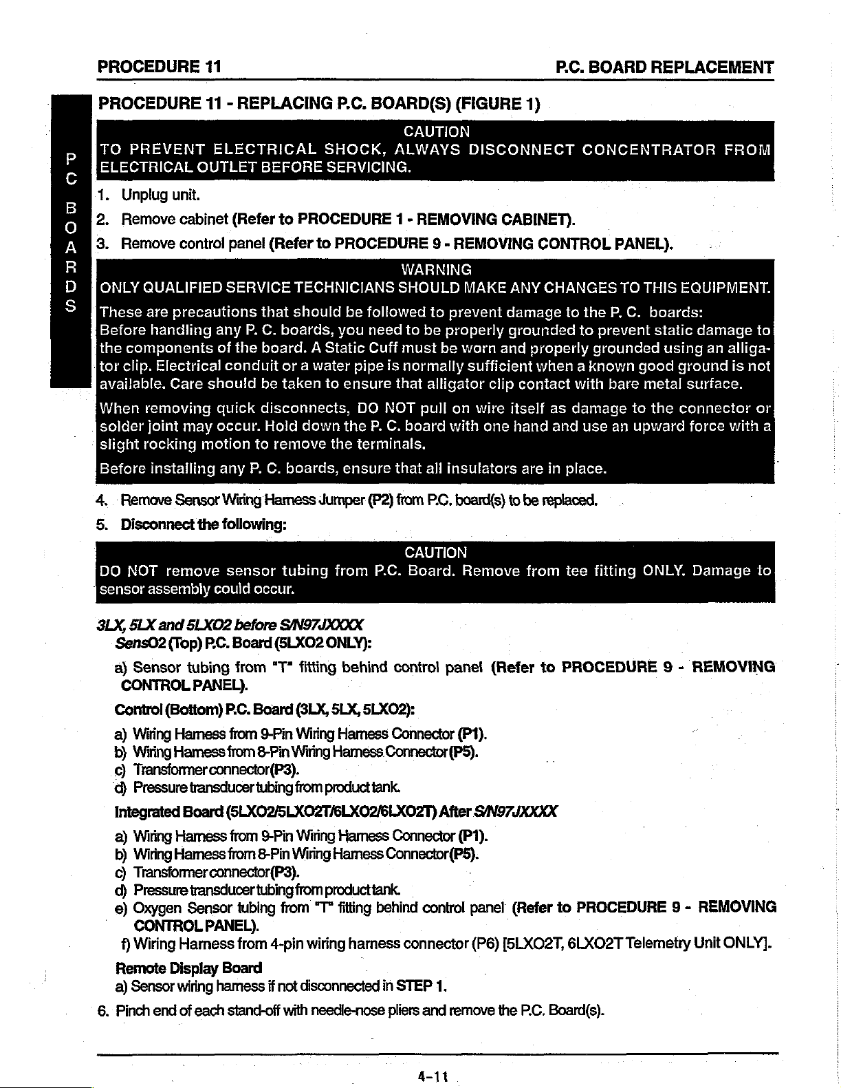
PROCEDURE
TO
P
ELECTRICAL
C
1.
B
2.
0
3.
A
R
D
ONLY
S
These
Before
the
tor
available.
When
solder
slight
Before
4, . Remove
PREVENT
Unplug
Remove
Remove
unit.
cabinet
control
QUALIFIED
are
precautions
handling
components
clip.
Electrical
Care
removing
joint
may
rocking
installing
Sensor
11 - REPLACING
ELECTRICAL
OUTLET
any
of
should
quick
occur.
motion
any
BEFORE
(Refer
panel
to
(Refer
SERVICE
that
P.
C.
boards,
the
board. A Static
conduit
or a water
be
taken
disconnects,
Hold
to
remove
P.
C.
boards,
Wiring
Hamess
PROCEDURE 1 -
TECHNICIANS
should
P.C.
SHOCK,
SERVICING.
to
PROCEDURE
be
you
to
ensure
down
the
the
ensure
Jumper
BOARD(S)
CAUTION
ALWAYS
REMOVING
WARNING
SHOULD
followed
need
to
Cuff
must
pipe
is
normally
that
DO
NOT
pull
P.
C.
board
terminals.
that
(P2)
Кот
(FIGURE
DISCONNECT
9 - REMOVING
MAKE
to
prevent
be
properly
be
worn
sufficient
alligator
all
insulators
Р.С.
clip
on
wire
with
one
board(s)
1)
CABINET).
CONTROL
ANY
CHANGES
damage
grounded
and
contact
itself
hand
are
to
be
to
properly
when a known
as
and
in
place.
replaced,
CONCENTRATOR
PANEL).
TO
THIS
the
P,
C.
to
prevent
grounded
good
with
bare
metal
damage
use
to
an
upward
EQUIPMENT.
boards:
static
damage
using
ground
surface.
the
connector
force
FROM
an
alliga-
is
with
to
not
or
a
5.
Disconnect
DO
NOT
sensor
3LX,
assembly
SLX
Sens02
a)
Sensor
CONTROL
Control
a)
Wiring
b)
Wiring
©)
Transformer connector(P3).
d)
Pressure
Integrated
a)
Wiring
b)
Wiring
©
Transformer
d)
Pressure
e)
Oxygen
CONTROL
f)
Wiring
the
remove
and
5LXO2
(Top)
tubing
PANEL).
(Bottom)
Hamess
Hamess
transducer
Board
Hamess
Hamess
transducer
Sensor
Hamess
following:
sensor
could
before
PC.
Board
from
P.C.
from
from
(5LXO2/5LXO2T/6LXO2/6L.XO2T)
from
from
connector(P3).
PANEL).
occur.
(SLXO2
“T*
Board
9-Pin
8-Pin
tubing
9-Pin
8-Pin
tubing
tubing
from
4-pin
tubing
from
P.C.
S/N97JXXXX
ONLY):
fitting
(3LX,
Wiring
Wiring
from
Wiring
Wiring
from
from
behind
SLX,
5LXO2):
Hamess
Hamess
producttank.
Hamess
Hamess
producttank.
“T°
fitting
wiring
Connector(P5).
behind
hamess
CAUTION
Board.
control
Connector
Remove
panel
(P1).
(Refer
Connector(P5).
After
S/N97JXXXX
Connector
connector
(P1).
control
panel
(P6)
from
to
(Refer
to
[5LXO2T,
tee
fitting
PROCEDURE
PROCEDURE
6LXO2T
Telemetry
ONLY.
Damage
9 - REMOVING
9 - REMOVING
Unit
to
ONLY].
Remote
a)
6.
Pinch
Display
Sensor
end
wiring
hamess
of
each
Board
if
not
stand-off
disconnected
with
needle-nose
in
STEP
pliers
4-11
1.
and
remove
the
P.C.
Board(s).
P.C.
BOARD
PROCEDURE
11
PROCEDURE
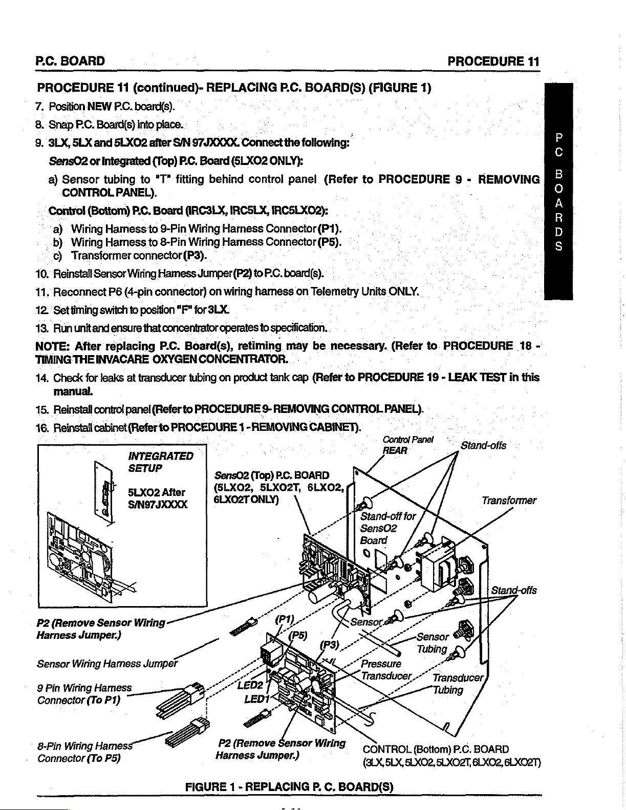
7.
Position
8.
Snap
9,
3LX,
SensO2
a)
CONTROL
Control
a)
_-b)
c)
10.’
Reinstall
11.
Reconnect
12.
Settiming
13.
Run
NOTE:
TIMING
14.
Check
manual.
NEW
P.C.
Board(s)
SLX
and
or
integrated
Sensor
Wiring
Wiring
Transformer
THE
tubing
(Bottom)
Harness
Harness
Sensor
P6
switch
únitand
After
ensure
replacing
INVACARE
for
leaks
11
(continued)-
PCC.
board(s).
into
place.
SLXO2
after
(Top)
to
"T"
PANEL).
P.C.
Board
to
to
connector
Wiring
(4-pin
connector)
to
position
that
OXYGEN
at
transducer
^
SIN
97JXXXX.
P.C.
fitting
(IRC3LX,
9-Pin
Wiring
8-Pin
Wiring
(P3).
Hamess
concentrator
P.C.
Jumper(P2)
"F"
for
Board(s),
CONCENTRATOR.
tubing
REPLACING
а
Connect
Board
(5LXO2
behind
IRCSLX,
Harness
Hamess
on
wiring
3LX.
operates
retiming
on
product
ONLY}:
control
IRCSLXO2):
Connector
Connector
to
P.C.
harness
to
specification.
tank
P.C.
BOARD(S)
the
following:
panel
board(s).
may
cap
(Refer
(P1).
(P5).
on
Telemetry
be
-
(Refer
:
necessary.
to
(FIGURE
to
PROCEDURE
Units
ONLY.
(Refer
PROCEDURE
1)
9 - REMOVING
to.
PROCEDURE
19 - LEAK
.
TEST
in
18
-
this
Ou
OODUDPOU
15,
Reinstall
46.
Reinstall
P2
(Remove
Harness
Sensor
9
Pin
Connector
Jumper.)
Wiring
Wiring
(To P1)
control
cabinet
panel
(Refer
INTEGRATED
SETUP
5LXO2
SIN97JXXXX
Sensor
Hamess
Hamess
Wiring
Jumper
(Refer
to
PROCEDURE
to
PROCEDURE 1 -REMOVING
SensO2
(SLXOZ,
After
|
9-
REMOVING
PC.
(Top)
SLXOZT,
プン
”
ono
CONTROL
CABINET).
BOARD
6LXO2,
PANEL).
REAR
Stand-offs
Transformer
8-Pin
Wiring
Connector
Hamess
(To
P5)
4
F2
(Remove
FIGURE
1 -
REPLACING
Ὃ
Wiring
É
P.
—
C.
BOARD(S)
CONTROL
(8LX,5LX,
(Bottom)
5LXO2,
P.C.
5LXO2T,
BOARD
6LXO2,
BLXO2T)
PROCEDURE
12
TRANSFORMER
PROCEDURE
TO
PREVENT
ELECTRICAL OUTLET
Unplug
>
Remove
Remove
ON
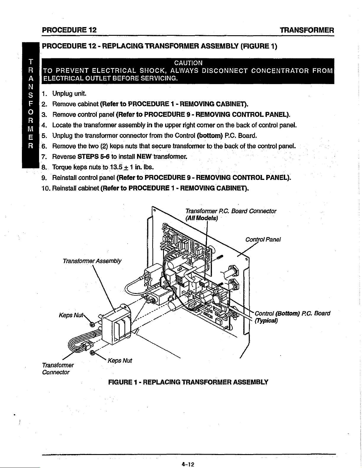
Locate
Unplug
DMSTONOZPIA
Remove
Oar
Reverse
Torque
DN
.
Reinstall
9
10.
Reinstall
unit.
cabinet
control
the
the
the
STEPS
keps
contro!
cabinet
12 - REPLACING
ELECTRICAL
BEFORE
(Refer
panel
transformer
transformer
two
(2)
5-6
nuts
panel
(Refer
(Refer
keps
to
to
13.5 + 1
to
assembly
connector
install
(Refer
to
TRANSFORMER
SHOCK,
SERVICING.
PROCEDURE
to
PROCEDURE
in
from
nuts
that
secure
NEW
in.
lbs.
to
PROCEDURE
PROCEDURE
CAUTION
ALWAYS
1 - REMOVING
9 - REMOVING
the
upper
the
transformer.
right
Conirol
transformer
9 - REMOVING
1 - REMOVING
Transformer
(All
ASSEMBLY
DISCONNECT
CABINET).
comer
(bottom)
Models)
on
to
the
CABINET).
PC.
(FIGURE
CONTROL
the
back
P.C.
Board.
back
of
CONTROL
Board
1)
CONCENTRATOR
PANEL).
of
control
the
control
Connector
panel.
panel.
PANEL).
FROM
Transformer
Transformer
Connector
Assembly
FIGURE 1 -
REPLACING
TRANSFORMER
Control
ASSEMBLY
Panel
ON/OFF
SWITCH
PROCEDURE
13
PROCEDURE
TO
PREVENT
ELECTRICAL
Unplug
=
Remove
Remove
Remove
Compress
FREON,
DO
NOT
install
Universal
properly
NOTE:
See
6.
Reverse
7.
Reinstall
installed.
Ensure
Detail A and
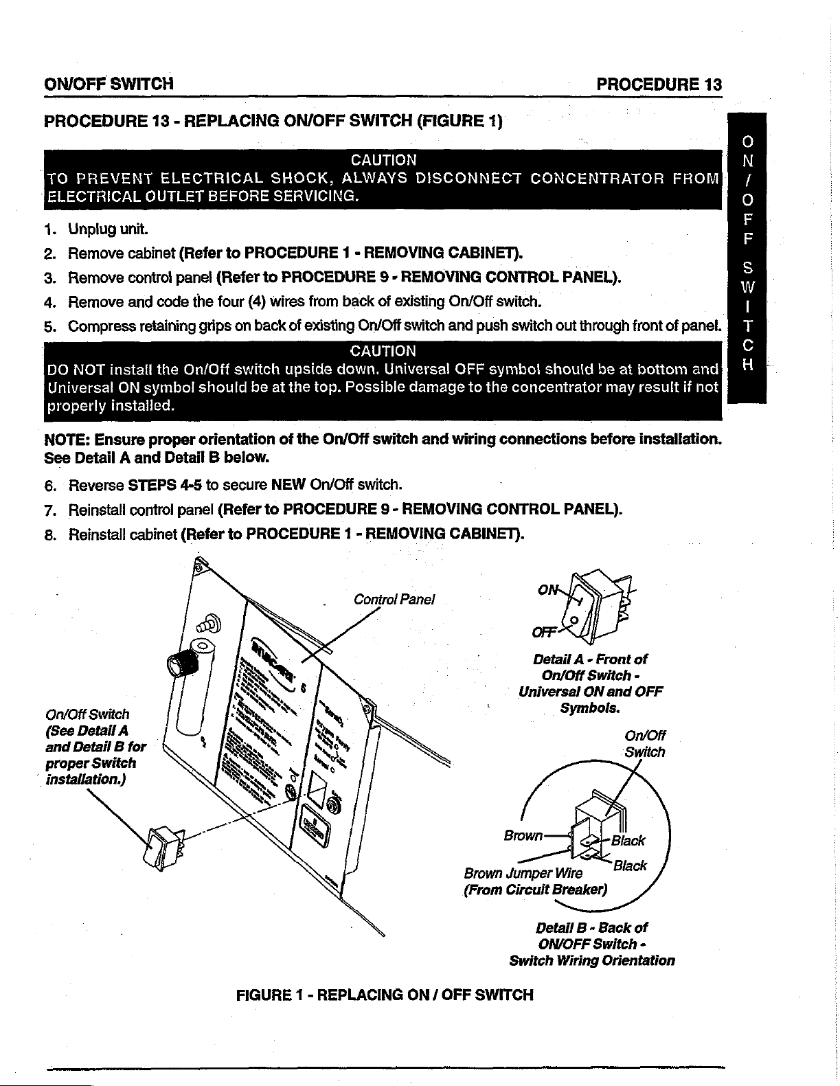
13 - REPLACING
ELECTRICAL
OUTLET
unit.
cabinet
control
and
(Refer
panel
code
retaining
the
On/Off
ON
symbol
proper
Detail B below.
STEPS
control
4-5
panel
SHOCK,
BEFORE
(Refer
the
four
grips
should
to
SERVICING.
PROCEDURE 1 -
to
(4)
wires
on
back
switch
be
at
orientation
to
secure
(Refer
NEW
to
ON/OFF
PROCEDURE
from
of
existing.
upside
the
of
PROCEDURE
top.
the
On/Off
On/Off
dawn.
SWITCH
CAUTION
ALWAYS
REMOVING
9 - REMOVING
back
of
On/Off
CAUTION
Universal
Possible
switch
switch.
9 - REMOVING
(FIGURE
DISCONNECT
CABINET).
existing
switch
On/Off
and
damage
and
1)
CONTROL
switch.
push
OFF
symbol
to
the
wiring
CONTROL
CONCENTRATOR
PANEL).
switch
concentrator
out
through
should
connections
PANEL).
front
be
at
may
before
FROM
of
panel.
bottom
result
if
and
not
installation.
zo
nno-
E00
Io3-
8.
Reinstall
On/Off
(See
Detail
Detail
and
proper
installation.)
Switch
A
B
Switch
cabinet
for
(Refer
to
PROCEDURE
1 -
REMOVING
Control
Panel
CABINET).
Brown
(From
Detail À -
On/Off Switch
Universal
Brown
Jumper
Circuit
Detail B -
ON/OFF
Switch
Front
ON
Symbols.
Wire
Breaker)
Back
Switch
Wiring
Orientation
and
o
of
-
OFF
or
of
-
FIGURE 1 -
REPLACING
ON / OFF
SWITCH

PROCEDURE
14
FLOWMETER
PROCEDURE
nmamesorm
10.
TO
PREVENT
ELECTRICAL
Unplug
Remove
Remove
Remove
Remove
Remove
Install
Reinstall
Run
PASAR»
new
unit
19 - LEAK
Reinstall
14 - REPLACING
ELECTRICAL
OUTLET
unit.
cabinet
control
tygon
palnuts
flowmeter
control
and
(Refer
panel
tubing
from
flowmeter
panel
check
TEST).
cabinet
(Refer
BEFORE
to
PROCEDURE
(Refer
from
rear
of
from
front
reversing
(Refer
for
leaks
to
FLOWMETER
SHOCK,
SERVICING.
to
PROCEDURE
the top
and
flowmeter.
of
contro!
STEPS
to
PROCEDURE
where
PROCEDURE
tygon
(FIGURE
CAUTION
ALWAYS
1 - REMOVING
9 - REMOVING
bottom
panel.
4-5.
fittings
9 - REMOVING
tubing
1 - REMOVING
engages
1)
DISCONNECT
CABINET).
CONTROL
on
back
of
|
CONTROL
flowmeter
CABINET).
CONCENTRATOR
flowmeter.
fittings
PANEL).
PANEL).
(Refer
to
FROM
PROCEDURE
Flowmeter
Flowmeter
(Back
Fittings
of
Flowmeter)
FIGURE 1 -
REPLACING
FLOWMETER
Control
Panel
4-14
HOUR
METER
PROCEDURE
15
PROCEDURE
TO
PREVENT
ELECTRICAL
Unplug
Remove
Remove
Remove
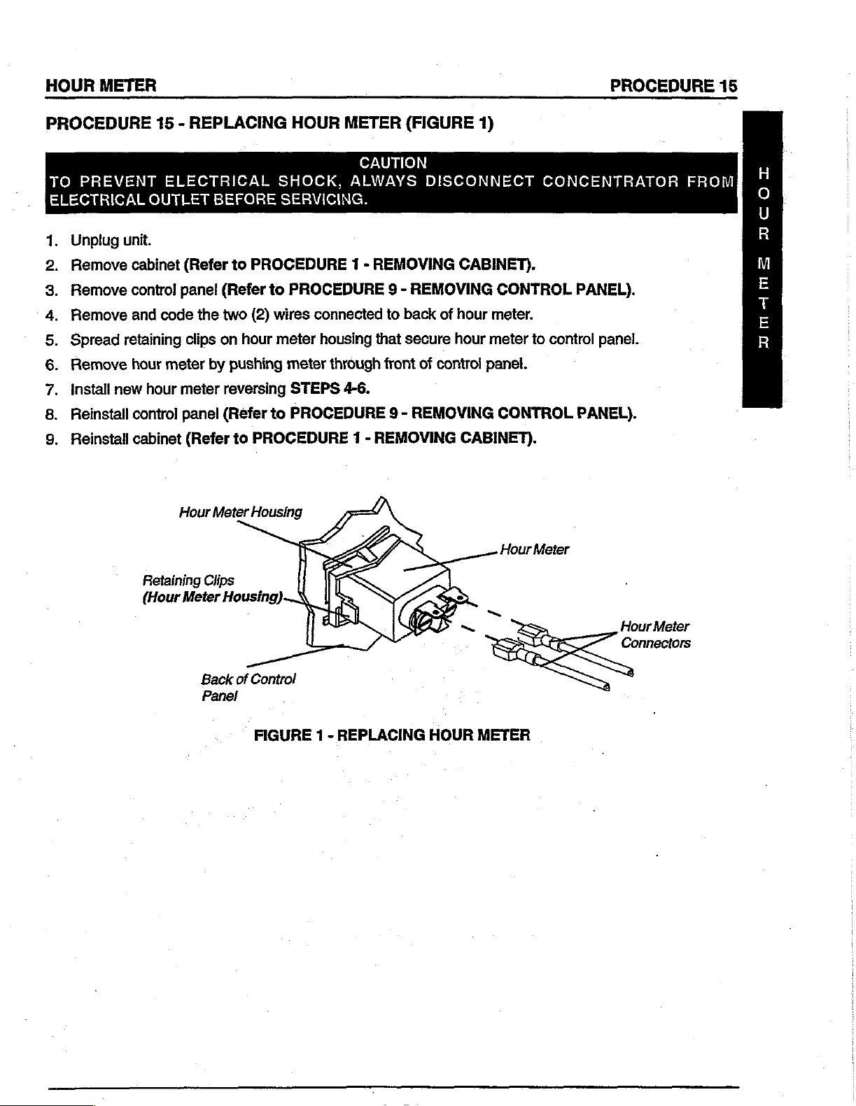
Spread
Remove
Install
σσ.
new
Reinstall
Reinstall
op
15 - REPLACING
ELECTRICAL
OUTLET
unit.
cabinet
control
and
retaining
hour
control
cabinet
code
meter
hour
(Refer
panel
clips
meter
panel
(Refer
Hour
BEFORE
to
(Refer
the
two
on
by
pushing
reversing
(Refer
to
Meter
HOUR
METER
SHOCK,
SERVICING.
PROCEDURE
to
PROCEDURE 9 -
(2)
wires
connected
hour
meter
to
housing
meter
STEPS
through
4-6.
PROCEDURE 9 -
PROCEDURE 1 -
Housing
(FIGURE
CAUTION
ALWAYS
DISCONNECT
1 - REMOVING
REMOVING
to
back
that
secure
front
of
REMOVING
REMOVING
1)
CABINET).
of
hour
hour
control
panel.
CABINET).
CONTROL
meter.
meter
to
CONTROL
CONCENTRATOR
PANEL).
control
panel.
PANEL).
FROM
DCOT
μμ
Retaining
(Hour
Meter
Back
Panel
Clips
Housing)
of
Control
FIGURE
1 -
REPLACING
HOUR
Hour
~
METER
Meter
Hour
Meter
Connectors
PROCEDURE
16
4-WAY
VALVE
PROCEDURE
TO
ELECTRICAL
Replacing
ES
1.
‘Position
oP oN
ш<гр<
valve
Torque
could
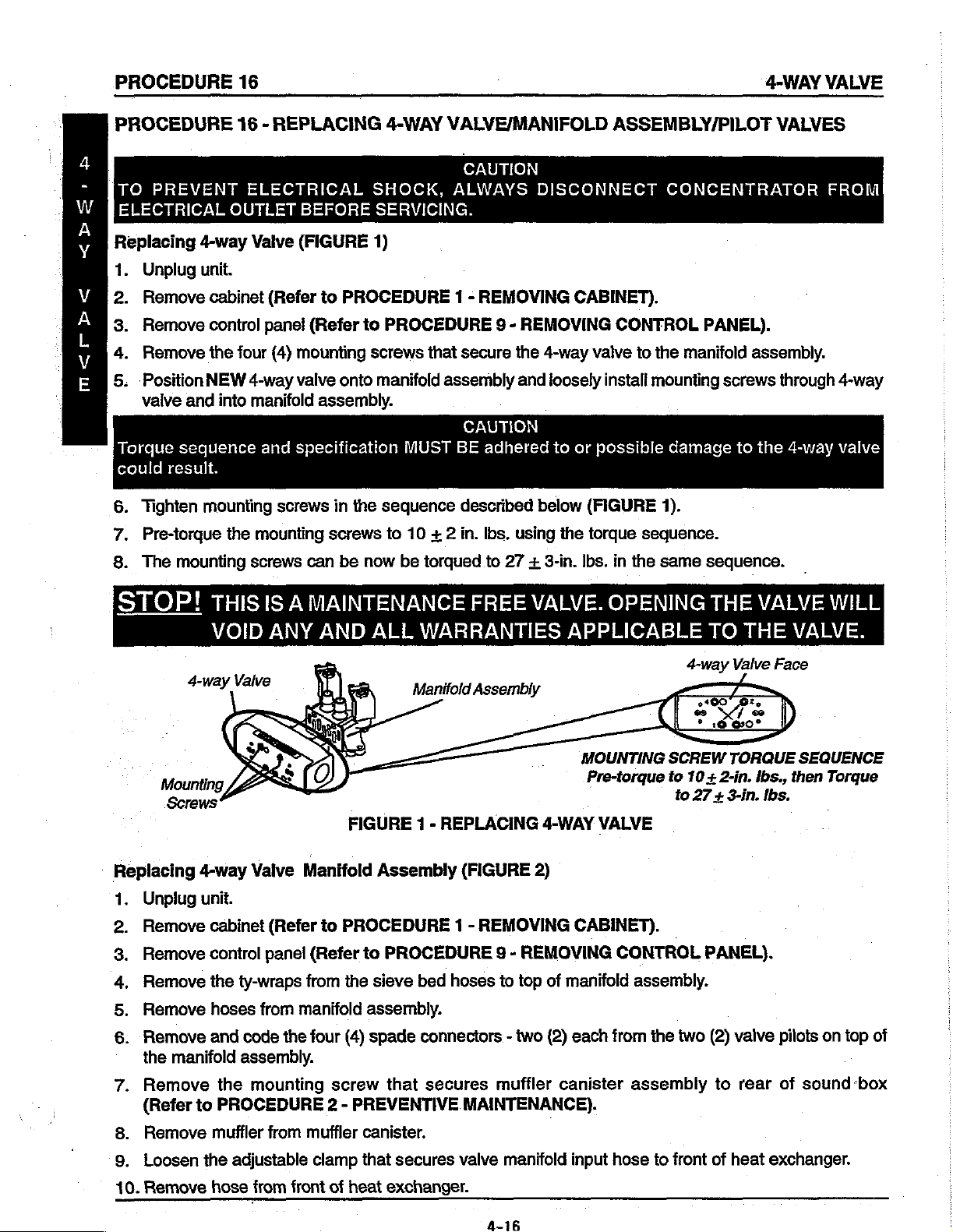
Tighten
6.
7.
The
8.
PREVENT
4-way
Unplug
Remove
Remove
Remove
Pre-torque
unit.
cabinet
control
the
NEW
and
sequence
result.
mounting
mounting
into
16 - REPLACING
ELECTRICAL
OUTLET
Valve
four
4-way
manifold
the
screws
BEFORE
(FIGURE
(Refer
panel
(Refer
(4)
mounting
valve
assembly.
and
specification
screws
mounting
can
to
screws
4-WAY
SHOCK,
SERVICING.
1)
PROCEDURE
to
PROCEDURE
screws
onto
manifold
MUST
in
the
sequence
to
be
now
be
VALVE/MANIFOLD
CAUTION
ALWAYS
1 - REMOVING
that
secure
assembly
CAUTION
BE
adhered
described
10 + 2
in.
torqued
lbs.
to
DISCONNECT
CABINET).
9 - REMOVING
the
4-way
and
loosely
to
or
below
using
the
27 + 3-in.
Ibs.
ASSEMBLY/PILOT
CONCENTRATOR
CONTROL
valve
to
the
manifold
install
mounting
possible
(FIGURE
torque
in
damage
1).
sequence.
the
same
PANEL).
assembly.
screws
to
the
sequence.
VALVES
through
4-way
FROM
4-way
valve
STOP!
Replacing
Unplug
Remove
Remove
Remove
Remove
Remove
POIANA
the
4-way
unit.
control
manifold
THIS
IS A MAINTENANCE
VOID
Valve
cabinet
panel
the
ty-wraps
hoses
and
from
code
assembly.
ANY
Manifold
(Refer
(Refer
from
manifold
the
four
AND
2)
ALL
FIGURE 1 -
to
PROCEDURE
to
the
assembly.
(4)
spade
WARRANTIES
Manifold
Assembly
PROCEDURE
sieve
bed
connectors - two
FREE
Assembly
<<
REPLACING
(FIGURE
1 -
REMOVING
9 - REMOVING
hoses
to
top
VALVE.
APPLICABLE
MOUNTING
.
Pre-torque
4-WAY
2)
of
(2)
VALVE
CABINET).
manifold
each
OPENING
4-way
SCREW
to
10
to
CONTROL
assembly.
from
the
two
THE
TO
Valve
Sá
TORQUE
+ 2-in.
27
+ 3-in.
PANEL).
(2)
valve
VALVE
THE
Face
lbs.,
Ibs.
pilots
WILL
VALVE.
SEQUENCE
then
Torque
on
top
of
8.
9.
10.
Remove
(Refer
Remove
Loosen
Remove
the
to
PROCEDURE
muffler
the
adjustable
hose
mounting
from
muffler
clamp
from
front
screw
2 - PREVENTIVE
of
that
canister.
that
secures
heat
exchanger.
secures
muffler
MAINTENANCE).
valve
manifold
canister
input
assembly
hose
to
front
of
to
rear
heat
exchanger.
of
sound
«box
4-WAY
VALVE
PROCEDURE
16
PROCEDURE
TO
PREVENT
ELECTRICAL
Spade
Connectors.
(STEP
i
'
Muffler
w/Exhaust
(STEP
16 - REPLACING
ELECTRICAL
OUTLET
Ty-wraps
(STEP
6)
4)
x
İSA
4-way
Valve
(STEP
13)
,
Canister
Hose
15)
BEFORE
N
¿(9
©
4-WAY
SHOCK,
SERVICING.
VALVE/MANIFOLD
à
Sieve
Mounting
A
5
__
Adjustable
Clamp
n
(STEP
Ty-wraps
(STEP
Compressor
Output
(STEP
Hose
17)
CAUTION
ALWAYS
Bed
Hoses
Detail
Assembly
16)
14)
ASSEMBLY/PILOT
DISCONNECT
(STEP
(STEP
5)
for
Manifold
11)
°
CONCENTRATOR
Heat
Exchanger
o
NOTE:
does
NEW
NOT
have
VALVES
FROME
(Typical)
Adjustable
Clamp
|
valve ” Manifold
Input
rose
(STEP
Heat
9)
Exchan
fins.
4
-
W
A
Y
V
A
上
WWA
Е
ger
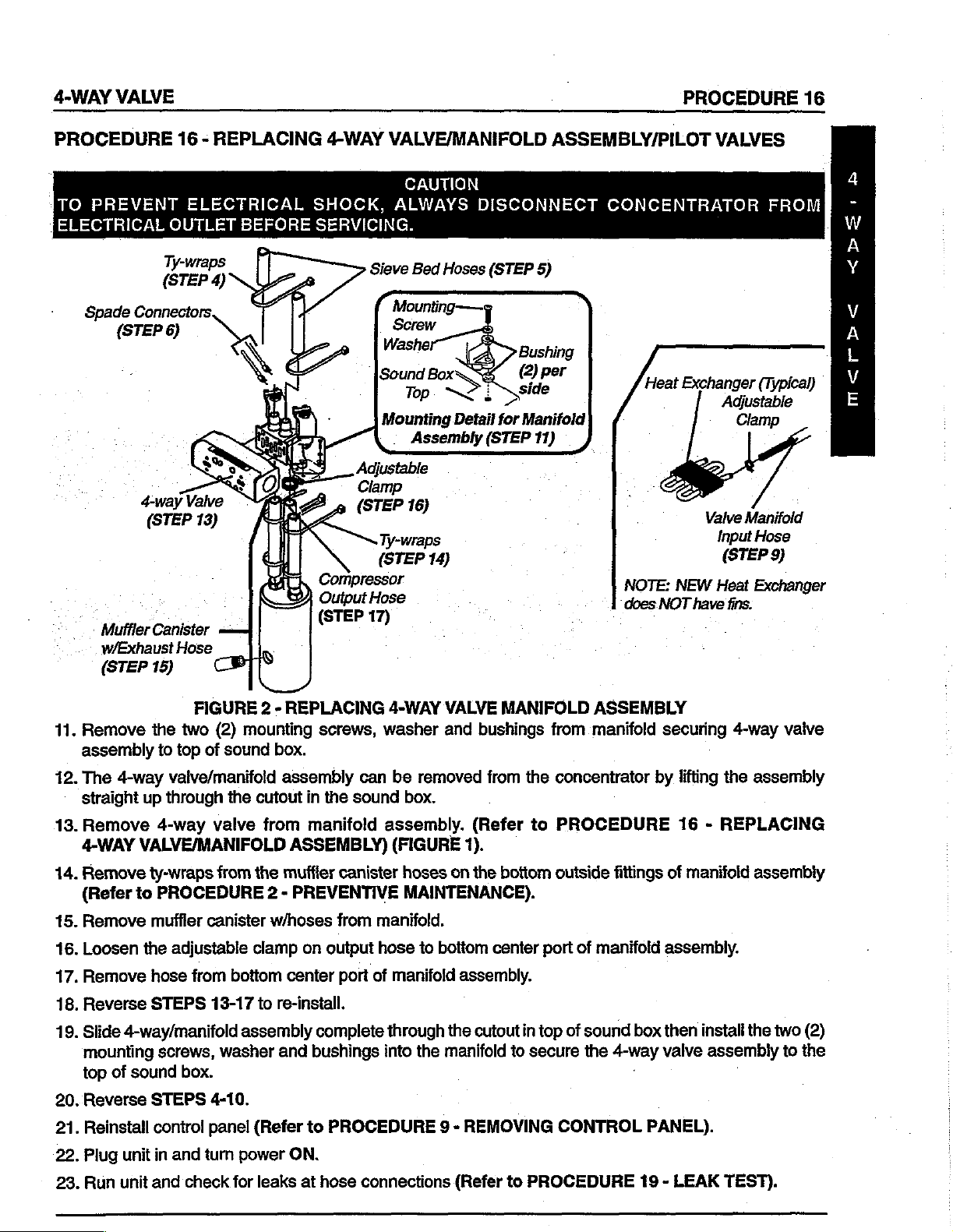
11.
Remove
assembly
12.
The
straight
13.
Remove
4-WAY
14,
Remove
(Refer
15.
Remove
16.
Loosen
17.
Remove
18.
Reverse
19.
Slide
mounting
top
20.
Reverse
21.
Reinstall
22.
Plug
FIGURE 2 -
the
two
to
top
of
4-way
of
valve/manifold
up
through
4-way
VALVE/MANIFOLD
ty-wraps
to
PROCEDURE
muffler
the
hose
STEPS
4-way/manifold
screws,
sound
STEPS
controi
unit
in
valve
canister
adjustable
from
13-17
box.
4-10.
panel
and
turn
(2)
mounting
sound
the
cutout
from
the
clamp
bottom
to
assembly
washer
(Refer
power
REPLACING
screws,
box.
assembly
in
from
manifold
ASSEMBLY)
muffler
can
the
sound
canister
2 - PREVENTIVE
w/hoses
center
re-install.
and
on
output
complete
bushings
to
PROCEDURE
ON.
from
port
of
4-WAY VALVE
washer
be
assembly.
(FIGURE
removed
box.
hoses
and
1).
on
MAINTENANCE).
manifold.
hose
to
bottom
manifold
through
into
assembly.
the
the
manifold
9 - REMOVING
MANIFOLD
bushings
from
the
(Refer
the
cutout
to
boftom
center
in
to
secure
ASSEMBLY
from
manifold
concentrator
PROCEDURE
outside
port
top
of
CONTROL
fittings
of
manifold
sound
the
4-way
securing
by
lifting
16 - REPLACING
of
manifold
assembly.
box
then
install
valve
.
PANEL).
4-way
the
assembly
assembly
the
assembly
vaive
two
(2)
to
the
23.
Run
unit
and
check
for
leaks
at
hose
connections
(Refer
to
PROCEDURE
19 - LEAK
TEST).
PROCEDURE
16
4-WAY
VALVE
PROCEDURE
VALVES
Replacing
24.
Check
25.
Re-install
Replacing
NOTE:
the
NOTE:
nectors
1.
2.
3.
Both
concentrator.
DO
aside
Hold
pilot
one
(1)
Unscrew
intact
on
Remove
STOP!
16
4-way
for
Valve
proper
cabinet
Pilot
Valve
pilot
NOT
remove
while
valve
complete
the
pilot
stem.
pilot
valve
DO
NOT
The
IS
NOT
will
(continued) - REPLACING
Manifold
system
(Refer
operation.
to
Poppets
valves
stem
can
spade
performing
with
turn.
valve
stem
poppet
REMOVE
Washer
DESIGNED
be
encountered
Assembly
(Refer
PROCEDURE 1 -
and
"O"
Rings
be
accessed
connectors
this
installation.
the
flat
blade
screwdriver
assembly
from
inside
from
the
THE
between
the
TO
that
4-WAY
(continued)
to
the
SPECIFICATION
REMOVING
(FIGURES 3 &
while
the
4-way
from
pilot
the
manifold
pilot
valve
COIL
YOKE
Bottom
BE
REMOVED
could
cause
VALVE/MANIFOLD
(FIGURE
2).
CABINET).
4).
valve
and
valve
and
stem.
coils.
turn
while
Simply
the
9/16-inch
leaving
FROM
of
the
Yoke
and
damage
ASSEMBLY/PILOT
section
sieve
THE
and
difficulty
of
this
bed
hoses
lay
coils
focknut
the
coil
with
COIL.
the
to
components.
Bottom
in
manual).
are
intact
with
spade
counterclockwise
yoke
and
of
on
con-
locknut
Coil
reassembly
4.
Set
DO
NOT
plastic
5.
Remove
6.
Discard
7.
Install
DO
NOT
rubber
aside
the
use
manifold
"O"
old
NEW
overtighten
"O"
ring
coil
with
sharp
and/or
ring
from
poppet
"O"
ring
and/or
yoke
tools
to
plastic
manifold
and
"O"
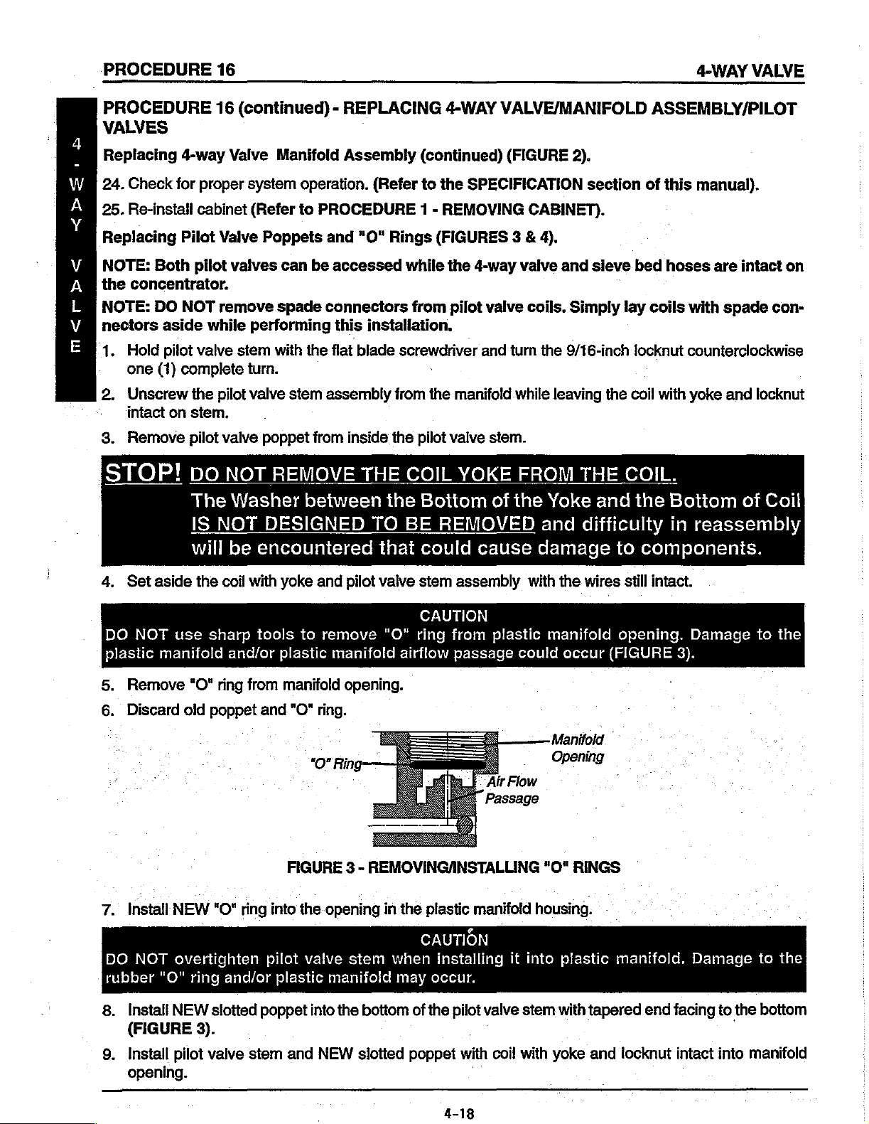
FIGURE 3 -
into
the
pilot
plastic
and
pilot
remove
manifold
opening.
ring.
0
REMOVINGANSTALLING
opening
valve
stem
manifold
valve
"O"
airflow
in
the
when
may
stem
assembly
CAUTION
ring
from
passage
Air
Passage
plastic
manifold
CAUTION
installing
occur.
with
plastic
could
Flow
housing.
it
into
the
wires
manifold
occur
Manifold
Opening
"O"
RINGS
plastic
still
intact.
opening.
(FIGURE
manifold.
Damage
3).
Damage
to
to
the
the
8.
Install
(FIGURE
9.
Install
opening.
NEW
3).
pilot
valve
slotted
poppet
stem
and
into
the
NEW
bottom
slotted
of
the
poppet
4-18
pilot
valve
with
coil
with
stem
with
yoke
tapered
and
tocknut
end
facing
intact
to
the
into
bottom
manifold

4-WAY
VALVE
PROCEDURE
16
PROCEDURE
VALVES
Sieve
Bed
Hoses.
Coil
Valve
Pilot
Body
‘Valve
(Reference)
FIGURE 3 -
16
(continued) - REPLACING
Valve
Pilot
р
Valve
(Reference)
REMOVINGANSTALLING
Body
PILOT
4-WAY
Yoke
Coit
_
VALVE
VALVE/MANIFOLD
oan
en
Pilot
Locknut
Spade
(Leave
Connectors
-L
>
T
ALP
Tapered
Manifold
Opening
POPPETS
AND
ASSEMBLY/PILOT
Stem
Valve
Connectors
Wire
Intact).
End
"O"
Slotted
"O"
Ring
RINGS
`
Poppet
10.
Use
to
25-inch
11.
Install
12.
Position
valve)
13.
Use
14.
Tighten
DO
DO
NOT
manifold
15.
Repeat
16.
Reposition
lower
sheet).
Ensure
lation.
the
flat
blade
Ibs. + 5-inch
NEW
pilot
to
ensure
the
flat
locknut
NOT
OVERTIGHTEN.
overtighten
may
the
FIGURE 3 PROCEDURE
lower
mounting
that
hoses
screwdriver
label
onto
valve
coil
spade
blade
screwdriver
clockwise
occur.
contro!
screws.
behind
ibs.).
pilot
valve
with
yoke
connectors
with
(Reference:
locknut
pane!
(Refer
control
and
tighten
coil
at
an
and
hold
the
9/16-inch
when
mounting
to
FIGURE 2 -
panel
pilot
yoke.
approximate
are
not
pulled
the
pilot
wrench
Torque
CAUTION
installing
for
other
screw
CAUTION
DO
NOT
valve
stem
60°
angle
or
tensioned
valve
stem
until
to
20-inch
it
onto
pilot
pilot
valve.
cut-outs.
REMOVING
contact
clockwise
to
the
after
in
place.
snug
to
secure
Ibs. + 3-inch
valve
behind
cooling
lower
CONTROL
until
snug.
left
(as
reinstallation.
the
stem.
mounting
PANEL
fan
after
(Reference:
viewed
stem
ibs.).
Damage
screws
in
control
from
and
to
this
panel
Torque
the
front
coil
with
yoke.
the
plastic
and
secure
instruction
reinstal-
of
17.
Reinstall
instruction
18.
Plug
19.
Reinstall
20.
If
any
(800)
upper
power
mounting
sheet).
cord
cabinet.
difficulties
832-4707
or
in
and
(Refer
are
encountered
in
Florida
screws.
tum
concentrator
to
FIGURE 1 -
1 -
(Refer
in
(407)
321-5630.
to
FIGURE 2 -
on
to
ensure
REMOVING
this
installation,
REMOVING
x
proper
CABINET
contact
CONTROL
operation.
in
this
instruction
Invacare
PANEL
sheet).
Technical
in
this
Service
at

PROCEDURE
17
PURITY
SWITCH
PROCEDURE
で
ご
TO
コー
PREVENT
DISCONNECT
TRICAL
ゴー
Operation
The
の
an
the
concentrator.
コー
の
〇
indicator
の
NOTE:
warm-up
unit
will
initial
the
if
other
condition
tor
illuminate.
Indicator
GREEN
YELLOW
concentrator
supplier.
that
RED
IMMEDIATELY
Supplier
.
Invacare 5 and 6 with
oxygen
purity
Concentrator
is
initially
illuminate.
startup, a GREEN
Oxygen
the
concentration
indicator
may
BACKUP
LIGHT - Total
17 - SENSO2
CAUTION
ELECTRICAL
CONCENTRATOR
OUTLET
purity
level
lights
time
that
be
Lights
LIGHT - Normal
LIGHT - You
Cal!
IMMEDIATELY.
BEFORE
indicator.
of
the
If
purity
falls
on
the
(approx.
turned
Within 5 to
Purity
used
unless
Section
level
light
requires
while
(FIGURE
instructed
Supplier
OXYGEN
to
BACKUP
contro!
can
ON,
illuminating
IMMEDIATELY.
ALARM
SHOCK,
SERVICING.
SensO2
This
feature
oxygen
30
service.
Operation.
may
is
unit
generated
below
no
is
alarm
panel!
be
used
minutes).
oxygen
30
light
will
of
the
in
specification.
waiting
.
1)
continue
otherwise
nearby.
shutdown.
OXYGEN
INDICATORS
ALWAYS
FROM
is
equipped
will
during
minutes
illuminate
Control
will
The
for a light
ELEC- | Auto
monitors
by
thresholds,
illuminate.
When
purity
signal
concentra-
to
use
by
Be
certain
Switch
supply.
with
the
initial
the
lights
after
in
Panel
Any
a
to
the
your
Call
AND
SWITCH
Oxygen
Shut-
Down
Use
Backup
Below
Purity
1.
Unplug
2.
Remove
REMOVING
3.
Locate
Board.
4.
Settheindicator
is
olds
manual).
5.
‘Plug
6.
Run
in
PROCEDURE.
7.
If
8.
Refer
TION
of
9.
(Refer
Normal
Normal
FIGURE
Indicator
unit.
cabinet.
purity
factory
in
the
in
power
unit
and
accordance
problems
fo
Operating
AND
this
manual.
operation
to
PROCEDURE
=
Purity
y,
cal
@
©
1 -
INDICATOR
Switch - If
(Refer
CABINET).
switch
preset
cord.
check
exist,
SEQUENCE
is
on
switch
to
at
73%).
SPECIFICATION
the
with
specifications
call
Invacare
Sequence
within
specification,
Suppli
PP
LIGHTS
Installed
to
PROCEDURE
upper
left
either
73%
(Refer
indicator
to
section
lights
Technical
in
OF
OPERATION
1 -
REMOVING
_
RED
YELLOW
~*~
GREEN
(FIGURE
comer
or
85%.
Alarm
for
set
the
reinstall
2)
of
Sensor
(Switch
Thresh-
of
operation
forth
in
Support.
INSTALLA-
portion
cabinet.
CABINET).
1
-
this
this
GREEN
-
Oxygen
to
use
ATELY.
NOTE:
board
switch
purity
located
unit.
(FIGURE
Refer
TION
NOTE:
If
(See
to - Alarm
section
LIGHT - with
sensor
the
your
is
then
indicators
on
PURITY
2).
Indicator
malfunctioning;
concentrator.
Invacare
equipped
you
can
the
sensor
INDICATOR
Thresholds
of
this
lights
YELLOW
Call
Concentrator
with
an
set
the
will
activate.
board
manual.
are
visible
LIGHT
Supplier
alarm
level
near
you
The
FLASHING
may
SensO,
at
the top
SWITCH
in
the
SPECIFICA-
only
continue
IMMEDI-
Р.С.
threshold
which
switch
of
the
is
the
graphic)
when
lit.
4-20
TOP-LEFT
LI
FIGURE 2 -
73%
85%
~
PURITY
Purity
Switch
+.
INDICATOR
Settings
SWITCH
TIMING
PROCEDURE
18
PROCEDURE
(FIGURE
TO
PREVENT
ELECTRICAL
To
accommodate
control
involves
1.
2.
A:
1.
Unplug
Remove
Plug
の
Run
Take
If
oxygen
の の か
ざさ
Unplug
UNITS
If
retiming
the
increasing
concentrator
unit
O2
WITH
18 - TIMING
1)
ELECTRICAL
OUTLET
for
varying
shifting
unit.
cabinet.
for
reading.
unit
of
the
or
decreasing
(Refer
in,
20
minutes.
conceniration
and
reinstall
CONTROL
is
needed, perform
THE
INVACARE
IRCSLX/5LXO2
CAUTION
BEFORE
tolerances
SHOCK,
SERVICING.
when
ALWAYS
replacing
INVACARE 5 and 6 Pressure
the
to
and
is
cabinet.
BOARD
PROCEDURE
tum
power
within
specification,
OR
the
switch
located
1 - REMOVING
on,
set
flow
retiming
LX
SMT
BOARD
following:
on
at 5 L/min.
CONCENTRATORS
DISCONNECT
components,
Equalization
the
lower
right
CABINET).
for
the
is
not
necessary.
CONCENTRATOR
an
adjustable
(P.E.)
side.of
Valve.
the
IRC5LX/IRC5LXO2.
Retiming
bottom
timer
P.C.
FROM
is
used
of a unit
Board.
to
OZ-E8-+
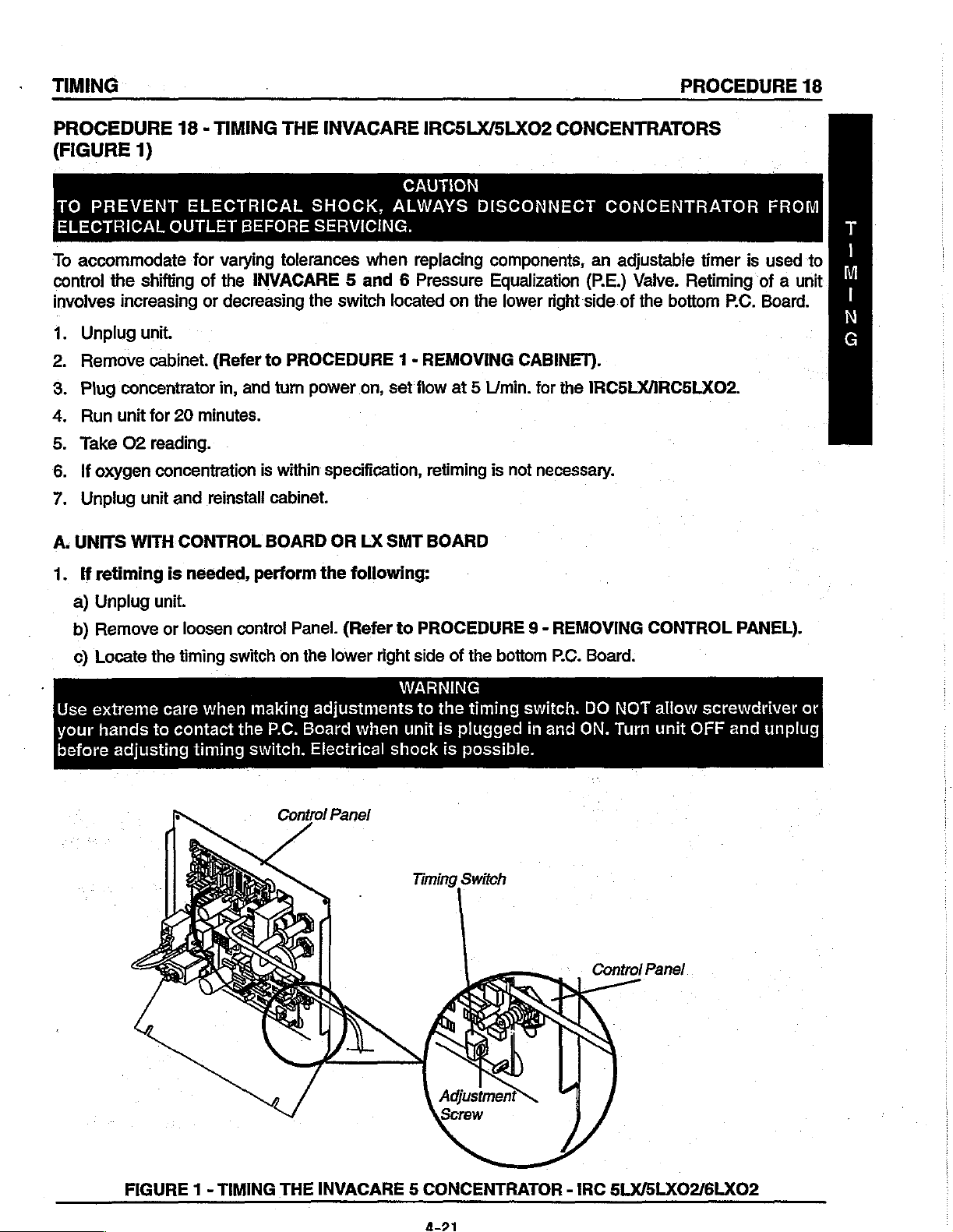
a)
Unplug
b)
Remove
c)
Locate
Use
extreme
your
before
hands
adjusting
unit.
or
loosen
the
timing
care
to
contact
switch
when
timing
contro!
Panel.
on
making
the
P.C.
switch.
Control
(Refer
the
lower
adjustments
Board
when
Electrical
Panel
to
PROCEDURE 9 -
right
side
of
WARNING
to
the
unit
is
plugged
shock
is
Timing
possible.
Switch
the
bottom
timing
REMOVING
P.C.
switch.
in
and ON.
Board.
DO
NOT
Turn
Control
CONTROL
allow
unit
Panel
screwdriver
OFF
PANEL).
and
unplug
or
FIGURE 1 -
TIMING
THE
INVACARE 5 CONCENTRATOR
-
IRC
5LX/5LX02/6LX02
PROCEDURE
18
TIMING
PROCEDURE
IRC5LX/5LXO2
e)
Insert a small
f)
コ
ミー
テー
の 〇
Set
2.
Turn
3.
If
after
one
4.
Let
positions
NOTE:
The
normal
5.
Continue
value
Once
Reinstall
Reinstall
SENE
Reinstall
unit
You
18
(continued) - TIMING
(FIGURE
common
the
timing
unit
on.
10
(1)
position
run
higher.
will
adjustment
to
achievable.
concentration
inlet
control
cabinet.
switch
minutes
lower
another
find
change
filter.
panel.
initially
of
run
than
10
minutes.
that
the
range
setting
(Refer
has
(Refer
(Refer
1)
or
flathead
at
the
time
the
concentration
the
previous
If
concentration
concentrator
is
between 3 and
one
(1)
step
to
CONCENTRATION
reached
to
specification,
to
PROCEDURE
PROCEDURE
THE
INVACARE 5 AND 6 CONCENTRATOR
screwdriver
number 7 position.
setting.
will
at a time
1 - REMOVING
into
the
is
below
is
lower
perform
A.
(up
or
LEVELS
retiming
9 - REMOVING
better
down)
Chart
is
adjustment
specification,
still,
change
at
in
complete.
CABINET).
screw
the
either
until
the
this
PROCEDURE
CONTROL
the
of
the
timing
change
switch
concentration
setting
to a number
higher
PANEL).
or
lower
of
switch.
to a number
two
setting.
is
the
highest
the
Manual
(2)
.)
PROCEDURE
18 - TIMING
5LXO2T/GLXO2/6LXO2T
B.
UNITS
To
accomodate
time
matic
If
manual
Automatic
Unattended
1.
2.
3.
4.
NOTE:
5.
WITH
INTEGRATED
the
of
the
pressure
(microprocessor
adjustments
adjustment
operation
Tum
power
Remove
a.
If
b.
ff
Replace
and 6 L/min.
The
After
the
tune
mode.
maximum
OFF
cabinet.
the
intergrated
the
intergrated
the
cabinet.
for
flow
MUST
FIRST
The
value
varying
the
valve
microprocessor
tolerances
egulization
controlled)
is
preferred,
is
performed
is
possible
and
unplug
(Refer
or
telemetry
or
telemetry
Plug
IRC6LXO2ARC6LXO2T.
be
shift,
of
oxygen
THE
INVACARE 5 AND 6 CONCENTRATORS
(FIGURE
OR
TELEMETRY
when
(PE.)
valve.
adjustments
please
by
the
without
the
unit.
to
PROCEDURE
board
board
concentrator
at
rated
output
the
front
pane!
automatically
concentration
1)
replacing
The
of
refer
to
onboard
the
use
1 -
has
beeen
has
NOT
in,
and tum
for
optimum
Red
for
the
BOARDS
components,
integrated
the
SECTION A of
microprocessor
of
any
REMOVING
LED
adjusts
unit
and
P.E.
shift
additional
replaced,
beeen
power
replaced,
on,
adjustment
will
slowly
the
at
rated
times.
CABINET).
set
length
an
adjustable
telemetry
this
manual
set
flow
blink.
flow.
boards
procedure.
to
optimize
adjustments.
the
timing
set
the
at5
of
oxygen
This indicates
of
the PE.
timer
allow
the
switch
timing
L/min.
forthe
output
valve
IRC5LXO2/
is
used
to
control
for
either
manual
oxygen
switch
timing
output
to
position
to
IRCSLXO2/IRC5LXO2T
for
that
the
up
concentration.
"0".
position
all
flow
unit
is
or
down
the
shift
or
auto-
“F”.
ranges.
in
the
auto-
to
provide
a.
If
the
b.
ff
the
If
the
front
When
the
LED
will
pauses.
switch
switch
change
This indicates
is
set
is
set
pane!
Red
auto-tune
procedure
from
to
to
LED
slowly
the
position
position
"0",
*F",
does
NOT
is
completed,
blinking
P.E.
timing
the
auto-tune
the
auto-tune
blink
or
to
rapid
value
will
take a minimum
will
take a minimum
the
unit
alarms
the
alarm
will
flashing.
the
microprocessor
Count
4-22
of
of
immediately,
sound
every
the
number
has
determined
three
45
check
3-4
seconds
of
(3)
hours
minutes
the
timimg
Red
LED
as
optimum
to
complete.
to
complete.
switch
and
the
flashes
for
position.
front
panel
between
maximum
Red
the

TIMING
PROCEDURE
18
oxygen
the
If
the
now
production.
manual
timing
function
-everytime
10.
If
the
timing
The
alarm
normally.
unit
is
turned
11.
The
timing
microprocessor
control
ing
by
to
SECTION A of
This
Red
mode.
switch
the
switch
should
The
switch
selecting
Record
was
normally.
unit
timimg
back
is
turned
was
stop
value
ON.
The
in
MUST
for
maximum
position
this
in
position
position
sounding
be
procedure.
CONCENTRATION
4
L/min.
LED
this
number.
timimg
back
is
stored
in
position
oxygen
"1"
to
LEVELS
count
"O"
corresponds
at
the
value
is
stored
ON.
"F"
at
the
start,
and
the
Red
in
the
microprocessor's
"0"
for
concentration.
"E".
Verification
CHART - (IRC5LX/SLXO2/6LXO2)
start,
tum
remove
LED
the
automatic
of
to
the
the
in
the
will
The
oxygen
same
numbers
unit
OFF
and
then
microprocessor's
the
cabinet
stop
memory
contro!
timing
production
and
flashing.
and
of
the
switch
can
MUST
02
95.6%
change
The
is
P.E.
Level
95.6%
95.6%
95.6%
on
the
BACK
memory
the
unit
will
recalled
valve
time
be
changed
be
performed
to
93%
to
93%
to
93%
to
91%
timing
on.
and
switch
The
is
recalled
position
now
function
everytime
by
the
to
in
unit
will
to
"0".
the
unit's
manual
accord-
|
O
5
L/min.
6
L/min.
95.6%
95.6%
to
to
87%
87%
PROCEDURE
19
LEAK
TEST
L
E
A
K
7
E
EN
UN
PROCEDURE
(FIGURES
PREVENT
İTO
DISCONNECT
ELECTRICAL
Test
Leak
Unplug
1.
Remove
2.
REMOVING
3.
Turn
the
4.
Let
concentrator
Apply
tings
leak
for
4-way
to
small
only.
test
pressure
Valve.
enter
19
1-3)
ELECTRİCAL
OUTLET
.
'
unit.
cabinet.
CABINET).
concentrator
amount
Avoid
4-way
into
all
Valve
leaks
DO
4-way
NOT
LEAK
-
CAUTION
TEST
SHOCK,
CONCENTRATOR
BEFORE
(Refer
run
CAUTION
of
other
around
Valve
to
on.
for
20
minutes.
leak
test
components.
body.
Sieve
allow
and
Carefully
leak
ALWAYS
SERVICING.
PROCEDURE
solution
leak
Bed
Hoses
test
system.
FROM
1
to
fit-
DO
NOT
test
at
solution
Sieve
4-way
to
65Τερς-),
-
Bed
Hoses
Valve
FIGURE 1 -
PE.
[BLX/5LX02/6LX02
4-WAY
Valve
Fittings
Hose
Bottom
of
(STEPS-a).
VALVE
Hose
Top
Beds
Fitting
Center
Valve
4-way
HOSES
Connections
Fittings
(STEP
of
5b).
on
Port
to
Sie
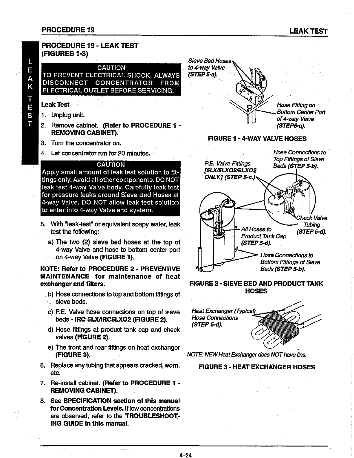
5.
With
“leak-test*
test
the
following:
a)
The
two
4-way
on
4-way
NOTE:
MAINTENANCE
exchanger
6.
7.
Refer
and
b)
Hose
connections
sieve
beds.
c)
P.E.
Valve
beds - IRC
d)
Hose
fittings
valves
e)
The
front
(FIGURE
Replace
etc.
Re-install
REMOVING
or
(2)
sieve
Valve
(FIGURE
any
and
Valve
to
PROCEDURE
for
filters.
hose
5LXARC5LXO2
at
and
rear
3).
tubing
cabinet.
CABINET).
equivalent
bed
hoses
hose
to
bottom
(FIGURE
maintenance
to
connections
product
2).
fittings
that
(Refer
1).
2 - PREVENTIVE
top
and
tank
on
appears
to
PROCEDURE
soapy
(FIGURE
water,
at
center
bottom
on
top
cap
and
heat
exchanger
cracked,
leak
the
top
port
of
heat
fittings
of
sieve
2).
check
worn,
of
of
NOTE:
1 -
All
Hoses
FIGURE 2 -
Heat
Exchanger
Hose
(STEP
NEW
FIGURE 3 -
SIEVE
Connections
5-d).
Heat
Product
(STEP
BED
HOSES
(Typical)
Exchanger
HEAT
to
Tank
Cap
5-d).
Hose
Connections
Bottom
Beds
AND
Fittings
(STEP
PRODUCT
does
NOT
have
EXCHANGER
to
of
Sieve
5-b).
TANK
fins.
HOSES
8.
See
SPECIFICATION
for
Concentration
are
observed,
ING
GUIDE
refer
in
this
section
Levels.
to
the
manual.
of
this
manual
!f
low
concentrations
TROUBLESHOOT-

ALARM
TEST
PROCEDURE
20
PROCEDURE
TO
PREVENT
ELECTRICAL
To
check
1.
POWER
mode
NOTE:
will
the
2.
LOW
a.
b.
Test
each
should
With
be
drained.
Battery
PRESSURE
Low
Failure
each
20 - ALARM
ELECTRICAL
OUTLET
alarm,
LOSS - With
sound
the
unit
If
power
Free™
product
in
the
tank
to
reach
following
circuit
BEFORE
CHECK
perform
the
the
audible
unplugged
failure
is
TEST-
pressure
the
set
AND
SHOCK,
SERVICING.
ALARMS
the
unit
running,
alarm
and
alarm
drained.
There
(pressure
point
pressure
manner:
SENSOR
CAUTION
ALWAYS
CAUTION
PERIODICALLY
following:
remove
immediately
inoperable
does
not
It
will
recharge
are
two
(2)
in
tank
within a prescribed
TEST
DISCONNECT
FOR
PROPER
the
line
cord
from
or
within
for a short
sound
when
seperate
failure
drops below a preset
period
with
unit
30
unit
modes
time
CONCENTRATOR
FUNCTION.
power
seconds.
is
Source,
of
time,
unplugged
plugged
for
Low
value,
limit,
or
The
power
the
Battery
and
in
and
Pressure.
typically 7 p.s.i).
Timeout
Free™
power
switched
Failure.
switch
FROM
loss
circuit
on.
alarm
on,
A
L
A
Β
M
T
同
S
T
Low
Pressure
cí.
With
unit
compressor
seconds.
c2.
With
unit
of
the
Shutdown
Time-Out
d.
NOTE:
Test
With
unit
unit
in
to
FIGURE 5 for
If
any
Test
(FIGURE
running,
relief
(Refer
product
to
running,
tank
Mode.)
(FIGURE
OFF,
and
turn
alarm
fails
1).
set
flow
valve
out
as
FIGURE 5 for
set
fiow
The
low
Replace
1)
disconnect
power
ON. The
Shutdown
to
perform
at
maximum
far
as
it
Shutdown
at
maximum
pressure
tubing
and
the
compressor
Time-Out
Mode.)
to
specification,
rating.
will
go
rating.
alarm
tywrap.
When
and
hold
Mode.)
Remove
should
activate
connector
Failure
the
main
it.
The
low
the
within
alarm
should
contact
valve
pressure
P.C.
board
30
seconds.
from
the
activate
Invacare
Compressor
[Disconnect
Harness(STEP
switches,
alarm
should
tubing
:
main
Technical
(tywrap)
(Refer
wiring
within
Molex
pull
the
activate
to
FIGURE 5 for
harness.
40
seconds.
Service.
Connector
from
2-b)].
stem
within
from
on
the
30
the top
Plug
(Refer
Relief
Valve
[Pull
Leak
FIGURE
Out
to
(STEP
1 -
Stem
Simulate
2-a)].
Compressor
LOW
PRESSURE
TEST

PROCEDURE
3.
HIGH
23
Test
High
PRESSURE
psi + 1
in
the
Pressure
20
p.s.i.
following
Test
(FIGURE
-
Occurs
manner:
when
2).
pressure
in
product
tank
|
rises
beyond a preset
ALARM
value,
TEST
typically
3-a.
sEiprp
ο
NOTE:
With
unit
remove
within
should
40
Set
flow
remove
If
any
alarm
(SHOWN
running
one
seconds.
at 3 l/min.
one
activate
(1)
RED
(1)
RED
within
fails
and
ORANGE
Wires
NOT
(DO
Remove).
Valve
4-way
FOR
REFERENCE)
flow
set
wire
from
(Refer
for
to
to
3LX, 5 L/min.
wire
from
30
seconds.
perform
Pilot
Valve
Ts.
at 3 L/min.
the
FIGURE 5 for
the
to
specification,
top
of
for
top
of
(Refer
for
Pilot
SLX/5LXO2
Pilot
We
NL
2
3LX, 5 L/min.
Valve
Shutdown
to
FIGURE 5 for
1.
or 6 L/min.
Valve
contact
1
for
The
high
Mode.)
1.
Tum
Shutdown
Invacare
É
ES
5LX/5LX02
pressure
for
6LXO2.
unit
ON.
Technical
RED
[Remove
STEPS
Pilot
or 6 L/min.
alarm
Turn
The
high
Mode.)
Service.
Wires
Either
3-a
Valve
1
for
should
unit
OFF
pressure
Wire
and
3-b)].
6LX02,
activate
and
alarm
-
4.
OXYGEN
a
preset
component
Test
in
the
Oxygen
Ensure
INDICATOR
4-8.
4-b.
4-c.
4-d.
Sensor
that
Turn
Monitor
With
Slowly
than
the
4-е.
Use
Clamp
supply
SENSOR
value,
following
typically
mechanical
Test
Purity
AND
SWITCH
unit
ON.
the
O2
the
O2
level
adjust
75%
but
unit
will
continue
care
not
off
the
line
from
FIGURE 2 -
(5LXO2/6LXO2) - Alarm
73% + 3%
or
electrical.
manner:
(FIGURE
Switch
Set
level.
flow
less
to
1/8-inch
(SW1)
in
output
greater
beyond
than
to
cut
oxygen
the
product
this
oxygen
3)
flow
than
84%.
run.
or
This
is
set
manual).
at.5
85%
maximum
Within
sensor
sensor
tank.
HIGH
85% + 2%.
test
at
L/min.
after 5 minutes,
rated
30
tubing
tubing
PRESSURE
sequence
is
performed
73%.
(6LX0O2)
flow
min.
the
CAUTION
when
between
This
(Refer
until
YELLOW
TEST
occurs
failure
or 6 L/min.
the
you can
when
indicates a catastrophic
in a series
to
PROCEDURE
GREEN
achieve a concentration
panel
clamping
the
oxygen
concentration
of
STEPS.
17 - SENSO2
(61X02).
panel
LED
LED
indicator
the
oxygen
sensor
will
sensor
and
levels
:
illuminate.
will
the tee
fall
failure
level
illuminate
tubing.
in
the
below
of
any
ALARM
greater
and
4-26

ALARM
TEST
PROCEDURE
20
44.
NOTE:
4-0.
Within
85%
Repeat
ALARM
4-h.
Unit
control
INDICATOR
4-i.
ai.
4k.
NOTE:
4-1.
4-m.
Your
NANCE
performed
Repeat
-
Within
Reset
If
Reinstail
If
Invacare
30
Setting
STEPS
INDICATOR
will
STEP
30
Purity
problems
any
alarm
concentrator
RECORD
on
the
1/8-inch
Oxygen
[Clamp
(STEP
min.,
the
Oxygen
is
NOT
available
4-a
again
pane!
AND
climb
LED
SWITCH
4-e.
min.,
the
Oxygen
Switch
arise
during
cabinet.
in
concentrator,
fails
to
this
LD.
Sensor
Off
4-e
(Refer
perform
manual
Flow
and
and
AND
to
will
to
desired
to
is
now
or
Tubing
4-i)].
Sensor
on
4-c
SWITCH
an
units
with
O2
Alarm
without
(SW1)
in
level
illuminate.
in
this
manual).
Sensor
test,
PROCEDURE
to
ready
to
record
any
Alarm
setting
contact
specification,
for
date
repairs
should
switch.
set
this
manual).
greater
(Refer
should
per
chart
Invacare
1 -
contact
an
additional
and
number
made.
activate.
at
85%.
than
85%
to
PROCEDURE
activate.
(FIGURE
Technical
REMOVING
Invacare
year.
of
(Refer
to
after 5 minutes
3).
Service
CABINET).
Technical
Use
the
hours
when
PROCEDURE
17 - SENSO2
for
further
Service.
PREVENTATIVE
preventive
17 - SENSO2.
and
the
GREEN
ALARM
assistance.
MAINTE-
maintenance
was
(STEP
4j)].)
Indicators
02
Purity
2%)
(+
85%
Over
73%
(+
3%)
to
85%
3%)
(+
73%
Below
|
Internal
{If
*Set
GREEN
(42%)
YELLOW
RED
Continuous
Alarm
Compressor
*
Factory
FIGURE 3 -
Switch
Present)
at
73%
Indicator
Indicator
Indicator
Sieve
Light
Audible
GARD™
Shutdown
Preset
OXYGEN
|
Light
Light}
-
at
SENSOR
Internal
(If
Present)
Set
GREEN
Indicator
RED
Continuous
Sieve
Alarm
Compressor
73%
TEST
Switch
at
85%
Indicator
Light
Audible
GARD™
Shutdown
NA
Light
-

PROCEDURE
5-a.
A
Test
上
A
P.E.
R
5-b.
M
om
二
P.E.
Coil,
in
the
Valve
With
P.E.
20
Valve
following
Coil
Coil
Coil
connection
Test
the
unit
running
Alarm
(IRCSLXO2
or
P.C.
manner:
(FIGURE
and
should
after
Board
4)
activate
flow
Circuitry
set
within
S/N
97JXXXxX) - Alarm
has
failed.
at 5 L/min:,
10
remove
seconds.
one
(Refer
RE.
sequence
(1)
yellow
to
FIGURE 5 for
Valve
wire
Coil
occurs
from
ALARM
when
the
the
P.E.
Shutdown
TEST
P.E.
Valve
Valve.
Mode.)
The
ALARM
il
High
Pressure
Low
Pressure
Time-Out
(30
Secs.)
Low
02
All
alarms
ON
and
IRC5LXO2
3LX, 5LX,
(BEFORE
INTERNAL
have
Compressor
FIGURE 4 -
5LXO2
S/N
97JXXXX)
LED
RED
On
On On
On
on
.
Shutdown,
ONLY - RED
Panel
ALARM
GREEN
Off
On
off
LED
P.E.
Horn
Yellow
VALVE
COIL
MODES
8LX,
5LX,
ALARM
Three
(3)
Startup
Short
Long
Continuous
Continuous
Beeps
Beep,
Pause
|
.
Continuous
Wires
TEST
5LXO2/5LXO2T,
(AFTER
INTERNAL
at
S/N
LED
RED
0 0
0
1 1
1
1
6LXO2/6LXO2T
97JXXXX)
FLASHES
GREEN
No
Problems - System
ok
O
Main
Power
Low
Pressure:
Major
2
High
Pressure:
No
Switching
3
commer
Loss
Leak
.
ON.
FIGURE 5 -
Continuous
Continuous
Continuous
Continuous
Continuous
Continuous
Continuous
*No
Shutdown,
All
alarms
5LX02/5LXO2T,
LED
ON.
ALARM
4-28
MODES
Unit
have
Compressor
6LX02/6LXO2T
1
1
2
2
2 4
2
3
continues
4
5
1
3
5
1
Pilot
Valve 1 Coil
Pilot
Valve 2 Coil
73%
Shutdown:
PE Valve
Eprom
Ram
Failure
Oxygen
to
run.
Shutdown,
ONLY - RED
Coil
Failure
Sensor
Hom
Panel
Low
02
Failure
ON
and

SIEVE
BED
PRESSURE
CHECK
PROCEDURE
21
PROCEDURE
PRESSURE
TO
PREVENT
ELECTRICAL
21 - SIEVE
CHECK
ELECTRICAL
OUTLET
BED
(FIGURES
BEFORE
PRESSURE
1, 2 &
SHOCK,
SERVICING.
3)
TAP-IN
CAUTION
ALWAYS
DISASSEMBLY
WARNING
Turn
power
1.
Remove
secure
cabinet
2.
Turn
3.
Loosen
product
4.
Pull
check
3LX
and
are
equipped
on the
from
restrictor.
the
the
the
from
unit
so
and
tank.
product
valve
5LX
left
top
rear.
Install
OFF
and
unplug
eight
cabinet
the
the
lower
tank
PVC
standard
with a restrictor
of
to
base
back
the
up
tubing.
CAUTION
the
DO
NOT
tap-in
(8)
5/8-inch
the
base
of
the
faces
adjustable
and
back
units
product
remove
kit
on the
unit.
screws
and
remove
concentrator.
you.
clamp
to
(without
assembly
tank
opposite
on
access
SensO2)
located
as
viewed
tubing
that
the
the
the
or
side.
KIT
INSTALLATION
DISCONNECT
INSTALLATION
1.
insert
the
"T"
fitting
Secure
2.
ing
3.
Attach
NEW
Insert
silicone
Secure
1/4-inch
“T”
fitting
the
1/4 x 2-inch
“T*
fitting
plug
into
tubing.
with a 1/4-inch
Pvc
Tubing
connection.
CONCENTRATOR
(FIGURE
into
clamps
and
secure
the
open
1/4"
*T*
AND
BED
2)
the
ends
of
to
each
end
silicone
with a 1/4-inch
end
of
the
」
clamp.
Clamp
Fitting
1/4 x 2-inch
Tubing
FROM
the
PVC
of
the
PVC
tubing
clamp.
1/4 x 2-inch
Silicone
tubing.
tub-
to
the
S
I
同
Vv
E
B
E
D
P
R
E
S
S
U
R
回
5.
Locate
right.
6.
Cut
in
half
Restrictor
SHOWN
Clarity
Adjus:
for
table
the
check
the PVC
valve
tubing
Clamp
FIGURE 1 -
:
i
and
PVC
tubing
below
the
Check
Cut
below
Valve
Tap-in
roduct
P
DISASSEMBLY
check
valve.
Valve
PVC
Tubing
Check
to
instail
Kit
to
your
Tank
PRESSURE
1.
Remove
1/4 x 2-inch
inch
clamp.
1/4"
Clamp
FIGURE 2 -
TESTING
plug
and
Connect
silicone
Plug
INSTALLATION
(FIGURE
tubing
and
pressure
3)
secure
gauge
to
with a 1/4-
the
Check
tight.
Turn
each
connection
the
concentrator
to
ON.
make
sure
they
are

SIEVE
BED
PRESSURE
CHECK
PROCEDURE
21
PROCEDURE
5
PRESSURE
|
E
V
NOTE:
E
liter
and 6 ne
B
NOTE:
E
D
system
before
р
R
4.
E
S
S
υ
5.
Β
E
6.
Adjust
flow
Wait
pressures
testing.
The
pressure
within
971)
and
the
4-way
After
the
concentrator
ing
within
971)
and
the
4-way
If
pressure
971)
and
valve
shifts
21 - SIEVE
CHECK
the
concentrator
(3
liters
for
for
. N
approximately 5 minutes
20
seconds
21
valve
4-way
20
21
valve
reading
21
3LX, 5 liters for
6LX02).
to
achieve
in
the
PSIG + .3
to
the
valve
will
drop
seconds
PSIG + .3
to
the
PSIG + .3
are
made,
BED
(FIGURES
proper
concentrator
to
20
PSIG + .3
(AFTER
opposite
shift,
the
to
14
PSIG + 2
to
20
PSIG + .3
(AFTER
opposite
is
20
PSIG + .3
(AFTER
proceed
PRESSURE
1, 2 &
to
_
971)
sieve
pressure
971)
sieve
971)
to
3)
MAXIMUM
SLX/SLXO2
to
equallibrium
should
(BEFORE
and
bed.
before
(BEFORE
and
bed.
(BEFORE
when
STEP
TAP-IN
allow
rise
shift
in
the
ris-
shift
both
9.
KIT
AFTER
1.
Insert
tubing
inch
2.
Reinstall
centrator.
INSTALLATION
TESTING
1/4-inch
onto
clamp.
the
;
the
cabinet
(FIGURE
plug
"T"
AND
and
1/4 x 2-inch
fitting
onto
and
the
BED
4)
base
:
secure
of
1/4-inch
Clamp
m
silicone
with
1/4-
the
con-
7.
If
pressure
the
specifications
TROUBLESHOOTING
8.
Turn
the
9.
Unclamp
the
"T"
fitting.
Restrictor
SHOWN
Clarity
for
|
Adjustable
in
the
concentrator
listed
concentrator
the
pressure
Clamp
OFF.
gauge
does
above,
section
and
STEP
/
é
o,
not
fall
refer
to
in
this
manual.
remove
1/4-inch
Clamp
Y
/
it
1.
Pressure
Gauge
/
“dg
into
the
from
FIGURE 4 -
AFTER
TESTING
FIGURE 3 -
PRESSURE
TESTING
4-30


RESPIRATORY
3
a
MM
2.5
ALLEN
MM
TOOLS
ALLEN
“T”
FT”
HANDLE
HANDLE
WRENCH
WRENCH
9”
9”
RW
AIR
#1
#2
GAUGE
PHILLIPS
PHILLIPS
STANDARD
LONG
NEEDLE
SLIP-JOINT
PUSH
SONDA
ROD
ASSORTED
TUBE
O2
LITER
OF
ANALYZER
METER
ACCETONE
NUMATICS
“LINT-FREE”
0-30
HEAD
HEAD
P.S.I.
SCREWDRIVER
SCREWDRIVER
SCREWDRIVER
NOSE
PLIERS
(WOOD
DOWEL,
WRENCHES
FLOURMATICS
OR
100%
CLEANER
SHOP
RAGS
PLIERS
1/2” X 6”)
“LOX
ALCOHOL
8”
JOINT
SEALANT
17.
18.
LEAK
DIGITAL
OPTIONAL
1.
2.
3.
4.
INVACARE
3/8”
NYLON
COMPRESSED
CAMEL
DETECTOR
VOLT
TOOLS
DRIVE
MALLET
HAIR
TECHNICAL
METER
SOCKET
AIR
BRUSH
TRAINING
SET
SOURCE
1-800-333-6900
X6697
ELYRIA,
OHIO

FIFTEEN-PIN
MOLEX
CONNECTOR
я
:0
e
FLOWMETER
IRC
501
PE
POWER
EXHAUST
SWITCH
FAN
LAMP
VALVE
(BLACK)
(BLACK)
-@
-©
(BLACK)
(BLACK)
>
ze
e
"0
-@
NEN
“6
POWER
FOUR
FOUR
IRC
POWER
HOUR
—
SOBNONAVN=
.
HOUR
=
POWER
=
EXHAUST
-=
.
COMPRESSOR
—
BROS
NOTE:
INVACARE,
SWITCH
WAY
WAY
501
VALVE
VALVE
PE
VALVE
SWITCH
METER
METER
CORD
FAN
COMPRESSOR
TECHNICAL
(WHITE)
(WHITE)
(WHITE)
(WHITE)
(WHITE)
(BLACK)
(WHITE)
(WHITE)
(WHITE)
(WHITE)
BACK
TO
TRAINING
OFF
ON
RELAY
N.O.
(ZETTLER
1-800-333-6900
RELAY
X6697
ON
P.C.
ELYRIA,
BOARD)
OHIO

INVACARE
Innovation
in
Health
Care.
|
Muffler
Kit
The
Turn
L
2. . Cut
3.
4
5.
6.
Number
following
OFF
Remove
sembly.
Remove
(2)
Loosen
1/-inch
Remove
Remove
panel
Upgrade
instructions
power
and
sections
and
the
eight
remove
the
existing
of
the
clamp
hose.
the
four
the
clear
2001154
apply
to
UNPLUG
(8)
"/s-inch
the
push
mount
pneumatic
*/z-inch
on
the
(4)
screws
tubing
braided
bottom middle
that
Kit
Mobilaire
the
cord
truss
cable
muffler,
tube.
that
secure
is
connected
HI
from
head
tie
TRC301)
WARNING
the
screws
that
secures
*/2-inch
straight
the
control
to
the
Assembly
and
Mobilaire V IRC501)
Mobilaire
that
secure
the
braided
fitting
bottom
of
|
panel
tube,
to
of
Oxygen
cabinet
pneumatic
*/2-inch
the
4-way
the
support
the
flowmeter
Installation
Instructions
upgrade.
Concentrator.
housing
valve
assembly
muffler
barb
"Y"
assembly
frame.
on
the
to
the
fitting
and
back
to
the
sound
and
remove
of
the
and
base
box
wall.
the
two
the
control
as-
7.
8.
NOTE:
9.
Move
Remove
This will
‘Remove
secure
Mutfier
S
κ
the
control
the
section
make
the
three
the
4-way
‘Straight
Fittings
and
1
Assembly
FIGURE 1 -
panel
of
the
access
(3)
*/s: x 2-inch
valve
~
一
一
A
ン
„T
to
the
right-side
support
to
assembly
27
27
~
INSTALLATION
the
~
一
一
frame
4-way
phillips
to
~
一
of
the
4-way
valve
assembly.
that
is
next
to
the
4-way
valve
its
mounting
二
で
assembly
head
screws,
bracket.
\
4
—Ák
me
iii
\
‹-
OF
THE
NEW
mounting
rubber
MUFFLER
valve
assembly.
bracket
spacers,
lockwashers
ASSEMBLY
easier.
and
nuts
(Please
that
tum
over)
|
5-3

Muffler
Replacement
Instructions
(Con't)
NOTE:
10.
11
12.
*NOTE:Use
13.
14,
Remove
Remove
Remove
assembly.
Attach
Clean
fitting
15.
16.
17.
Reinstall
screws,
Place
Place
and
Not
all
rubber
Flouramics
to
make
the
the
secure.
units
washers
the
two
the
4-way
the
bottom
sure
the
new
the
bottom
into
the
4-way
robber
7/2-inch
straight
have
the
or
(2)
clamps
value
middle
Lox-8*thread
that
the
elbow
fittings
middle
bottom
valve
assembly
spacers,
braided
hoses
hardware
lock
washers.
and
assembly
straight
sealant
to
straight
middle
hole
to
lockwashers
hose
and
with
fittings
hoses
from
fitting
sealant
doesn't
each
fitting
of
the
the
and
clamp
(muffler
as
listed
from
the
the
concentrator.
and
and
break
end
of
the
that
was
4-way
mounting
nuts.
over
the
assembly)
in
Step
top
of
the
the
two
apply
off
and
4-way
valve
removed,
valve
assembly.
bracket
straight
9.
Units
4-way
(2)
end
sealant
enter
assembly.
apply
using
fitting
over
built
valve.
straight
two
the
thread
the
existing
and
the
elbow
before
fittings
(2)
threads
4-way
valve.
sealant and
*/s: x 2-inch
secure.
fittings
91A
of
on
the
in
the
will
not
4-way
valve
on
the
fittings
reinstall
phillips
4-way
have
the
head
valve
NOTE:
18.
19.
21
When
Reroute
Place a piece(s)
hose
Reinstall
Reinstall
Attach
installing
existing
from
rubbing
the
support
cabinet
the
muffler
wires
over
of
black
against
flowmeter
frame
housing
*Flouramics
assembly,
the top
electrical
insert
hose
to
the
and
control
assembly
inc,
18
make
of
the
elbow
tape
between
hole.
back
of
the
panel.
to
the
base
Industrial
Avenue,
sure
that
fittings.
braided
control
assembly.
panel.
Mahwah, N307430
hoses
the
fan
leads
and
existing
(201-825-8110)
are
not
insert
disconnected.
hole
to
prevent
899
Clvelarid
Form
No.
Street * P.O.
91-124
(P/N
Box
4028 ° Elia,
2001153)
Ohio
440352125 * Phone
(Rev.
10/91)
INVACARE
innovation
(216
in
Health
3296000 * Tal
5-4
Care
..
Free
8003336900 * Telex
6873185
ICARE
LAV
.
Printed
in
U.S.A.

MOBILAIRE
τε
ROCCO n Heath
Care
me
COOLING
KIT NO.
KIT NO.
COOLING
and V MODELS
THIS
Part
2000817
or
1027358
2000755
2000862
yanl
4
2000754
1006525
Only
this
FAN
SERVICE
No.
Qualified
retrofit
procedure.
FAN
2001361
2001360
REPLACEMENT
IRC301/IRC501/IRC501C/
KIT
CONSISTS
Description
Exhaust
Exhaust
Cable
#10 x 1”
20000.
$
Trap
wep
Service
REPLACEMENT
(IRC301/501/501C)
(IRC501A)
FOR
OF
Fan
(IRC301/501/501C)
or
Fan
(501A)
Tie
Mount
Pan
Head
Screw
Sheet
er
Ba 4 Tapping
WARNING
Personnel
MOBILAIRE
should
11!
iRC501A)
Quantity
1
1
4
4
1
1
1
1
perform
and
To
prevent
centrator
1.
Unplug
2.
Remove
&
Remove
trol
panel
4.
Loosen
trol
panel
5.
Remove
duct
tank
product
&
Disconnect
(FIGURE
7.
Disconnect
flowmeter
Installation,
Operating
CAUTION
electrical
from
unit.
cabinet.
the
(FIGURE
the two
(FIGURE
the.clamp
to
the
tank
1).
the
on
shock,
electrical
더
two
(2)
upper
1).
(2)
tower
1).
that
secures
PC
board.
(FIGURE
molex
flowmeter
the control
1).
connector
always
outlet
screws
screws
Remove
tubing
panel
Assembly
Instructions
disconnect
before
con-
servicing.
that
secure
the
con-
that
secure
the
con-
」
the
tubing
on
the
pro-
the
tubing
from
the
on
the
PC
board
.
from
the
bottom
of
the
(FIGURE
1).
Form
No.
92-149
(2001362)
Rev.
11/92
FIGURE 1 —
REMOVING
5-5
THE
CONTROL
PANEL
Flowmeter
Product
Product
Tubing
Tank
Tank
Tubing

8.
Remove
compressor
9.
Remove
10.
Remove
11.
Remove
(FIGURE
12.
Disconnect
hamess
13.
Cut
harness
14.
Remove
panel
15.
Remove
to
caster
16.
Pull
17.
Cut
18.
Disconnect
19.
Disconnect
tapping
(301/501).
NOTE:
Before
20.
Remove
fan
21.
Replace
ting
wires
control
intake
hose
3).
molex
(FIGURE
and
remove
to
sound
compressor
side
of
four
base
compressor
four
(4)
tywraps
wires
fan
screw
removing
must
be
changer
and
screws
(FIGURE
fan
by
discard
cooling
(FIGURES. 2 and
from
the
relay
and
ON/OFF
panel.
hose
from
from
exhaust
connectors
3).
tywrap
that
box
support
green
sound
box
(4)
screws
(FIGURE
assembly
from
from
spade
green
grounding
on
fan
clips
positioned
3).
removing
screws
fan
using
hour
meter,
switch.
resonator
side
from
secures
rod
grounding
(301/501)
securing
3).
out.
heat
exchanger
lugs
wire
assembly.
note
the
position.
properly
four
(4)
screws
and
clips
new
clips
3).
flowmeter
(FIGURE
of
compressor
compressor
compressor
(FIGURE
wire
from
(FIGURE
compressor
(FIGURE
on
fan.
by
removing
Discard
These
to
secure
(FIGURE
and
heat
.
located
3).
four
(4)
light,
3).
wiring
wiring
3).
contro!
3).
bracket
3).
self-
screw
clips
ex-
under
moun-
WARNING
Fan
must
be
properly
blows
down
on
located
will
22.
©
tapping
23.
Secure
tywrap
24,
Replace
25.
Reverse
ponents
26.
Plug
points.
NOTE:
27.
If
28.
If
properly
occur.
FIGURE 2 —-
Reconnect
Run
unit
not,
fan
screw
heat
mounts
compressor
the
of
the
in
unit
unit
runs
call
service.
green
provided
exchanger
preceeding
and
for
properly,
located
the
compressor.
(Figure
POSITIONING
grounding
(301/501).
using
(FİGURE
(FIGURE
steps
concentrator.
test
for
correct
at
least % hour.
replace
so
2)
or
damage
THE
wire
four
3).
3).
and
pressure/leaks
cover.
air
from
The
fan
must
to
the
NEW
by
using
(4)
tywraps
reassemble
the
FAN
#6
to
the
all
.
fan
be
unit
Self-
fan
com-
at
test
Form
No.
92-149
(2001352)
Rew.
11/92

Form
No.
92-149
(2001362)
Rev.
FRONT
VIEW
OF
CONCENTRATOR
11/92
FIGURE 3 —
Hose - Exhaust
of
Compressor
Side
REPLACING
5-7
COOLING
FAN

MOBILAIRE”
し
ーー
キイ
ンー
=
COMPRESSOR
KIT
KIT
1.
2.
3.
4.
5.
6.
REPLACING
FROM
The
Mobilaire V (RC501,
1.
NOTE:
hoses,
2,
3.
4.
5.
6.
7.
NO.
INCLUDES
P/N
2001375 - One
P/N
2001370 - Two © Braided
P/N2000765-
tion
with
P/N
2001366 - One
P/N
1021149 - One
P/N
2001377 - One
HEAT
following
Turn
OFF
Oxygen
Removethe8x5/B-inch
housing
When
use
Remove
hose
exchanger
Remove
$07
assembly
Clean
was
removed
When
leave
compressor
piled
that
the
compressor
Apply
into
the
tighten.
insert
and
attach
Slide
and
position
assembly
2001378
THE
FOLLOWING:
One
(1)
Item
7.
THE
HOSE/90
EXCHANGER
instructions
501A
powerand
Concentrator.
assembly
elther a screwdriver
the
and
90
the
the
threads
applying
the
first
on
the
teflon
tefton
threaded
the
Spring
the
3-inch
fitting.
to
removing
two
(2)
degree
to
the
compressor
90
degree
and
discard.
in
with
isopropyl
teflon
two
(2)
housing
remainder
tape
assembly.
tape
and
holes
(Item
to
the
rear
braided
iton
the
OUTLET
(1)
Silicone
Stainless
(1)
Compressor
(1)
Plastic
Bag.
(1)
instruction
DEGREE
TO
COMPRESSOR
apply
to
and
IRC5010).
WARNING
UNPLUG
clamps
elbow
the
hose
the
truss
head
the
base
the
stainless
that
that
compressor
compressor
alcohol.
CAUTION
tape
to
threads
exposed.
of
the
doesn’t
install
the
of
the
compressor
3)
into
of
the
heat
sleeve
end
that
assembly.
or a 1/4-inch
assembly.
that
threads.
break
8.5-inch
(Item
Hose
8.5-inches
Sleeves
Steel
cord
secure
runs
the
Tefion tape
NEW
3-inches
Spring
Fitting
Sheet.
ELBOW
Mobifaire
fromthe
screws
that
steel
the
from
the
fitting
housing
new
straight
are
inserted
This
off
straight
assembly.
silicone
exchanger.
2)
onto
attaches
HOSE
long.
long.
used
in
(Straight).
THAT
ASSEMBLY
til
(IRC301)
Mobilaire
secure
clamps
socket
two
(2)
sections
rear
of
from
the
where
fitting,
into
will
be
is
to
ensure
and
enter
fitting
hose
the
silicone
to
the
compressor
conjunc-
RUNS
and
cabinet
from
the
wrench.
of
the
heat
compres-
the
fitting
the
ap-
the
(item
4)
Securely
(item
1)
hose
8.
Securely
9.
Loosen
remove
exchanger
10.
Slide
and
NOTE:
11.
Securely
12.
Attach
tighten
the
the
hose
to
the
3-inch
position
it on
This
wiil
tighten
cabinet
Installation
Assembly
the
stainless
stainless
the
protect
steel
end.
(This
in-line
braided
the
hose
the
the
stainless
assembly
clamp
hose
filter.)
sleeve
end
that
hoses
to
the
Instructions
steel
clarnps.
(at
the
in-line
runs
from
the
(item
2)
onto
attaches
during
steel
base
tothe
shipment.
camp.
assembly.
frontof
the
silicone
in-line
And
filter)
and
the
heat
hose
filter.
BEFORE
INSTALLATION
INSTALLATION
FIGURE
FROM
1 -
HEAT
REPLACING
EXCHANGER
THE
HOSE/90
TO
COMPRESSOR
DEGREE
ASSEMBLY
ELBOW
Form
No.
93-12
1301
Silver
(2001377)
Lake
Drive * Sanford,
innovation
Florida
in
Health
Care
=
32773 « Phone
(407)
321-5630
Printed
in
U.S.A.

IRC3LX
PILOT
KIT
VALVE
PART
/IRC5LX
POPPET
NO.
2003083
/IRC5LXO2
REPLACEMENT
Assembly,
Installation
and
Operating
Instructions
OZ
=
INVACARE
ue
.
SAFETY
The
following
safe
installation
ment
Kit:
DO
NOT
READING
INSTRUCTIONS.
UNDERSTAND
INSTRUCTIONS,
DEALER
(800-
832-4707)
INSTALLATION.
PERSONAL
DAMAGE.
TECHNICIANS.
INSTALLATION.
Check
damage
Canier/Invacare
Unplug
recommendations
INSTALL
AND
OR
INVACARE
INJURY
ONLY
all
parts
is
found,
concentrator
SUMMARY
are
of
the
Pilot
Valve
Poppet
WARNING
THIS
KIT
WITHOUT
UNDERSTANDING
IF
YOU
THE
WARNINGS,
CONTACT
BEFORE
IMPROPER
AUTHORIZED
SHOULD
for
for
further
ARE
YOUR
TECHNICAL
PERFORMING
USE
AND/OR
PERFORM
shipping
DO
NOT
instructions.
before
beginning.
UNABLE
CAUTIONS,
MAY
EQUIPMENT
AND
damage.
use.
made
for
Replace-
FIRST]
THESE
TO
AND
INVACARE
SERVICES
THIS
CAUSE
QUALIFIED
THIS
Contact
the
If
REMOVING
(FIGURE
1.
Unplug
2.
Remove
cabinet
cabinet
NOTE:
exposed
3.
Cabinet
When
foam
‘To
re-install
Assembly
THE
1)
WARNING
unit.
the
eight
assembly
straight
up.
required,
insulation.
cabinet,
CABINET
(8)
mounting
to
the
vacuum
reverse
Base
screws
base
assembly
inside
STEP
Assembly
Mounting
of
the
2.
Screws
that
secure
and
lift
the
cabinetand
(8
each)
Ensure
Tools
1.
2.
3.
This
that
installed.
Refer
to
Part
No.
Required:
One
(1)
One
Flat
One
Phillips
kit
includes
Slotted
Poppet
N
"O"
Ring
PILOT
all
items
the
IRC3LX
2002728
9/16-inch
Blade
Screwdriver
Head
the
VALVE
POPPET
are
properly
and
5LX
Rev.
Level
Boxed
End
Screwdriver
following:
DESCRIPTION
Slotted
"O"
Labels
Rings
Poppets
2X897A
KIT
and
securely
Service
2/97
Wrench
Manual
for
assistance.
L-96,
COMPONENTS
REMOVING
-
(FIGURE
NOTE:
Service
necessary.
1.
2.
3.
-
forward
Move
Panel
rest
FIGURE 2 -
FIGURE 1 -
2)
Refer
Remove
secure
Loosen
secure
Grasp
concentrator.
out
out
Sound
to
Manual
Control
and
front
Sound
for
the
two
the control
the
two
the
control
the
control
allowing
Control
let
it
of
Box
Bo:
REMOVING
REMOVING
THE
the
CONTROL
IRC
3LXARC5LX/IRC5LXO2
assistance
(2)
upper
panel.
.
(2)
lower
panel.
panel
control
Panel
panel
and
THE
THE
CABINET
in
this
mounting
mounting
gently
to
rest
Upper
Mounting
CONTROL
Form
PANEL
procedure
screws
screws
lift
in
front
Screws
(Remove)
Lower
(Loosen)
and
of
Mounting
Screws
PANEL
No.
97-108
that
that
the
if
-
」
pull
5-9

REMOVING/INSTALLING
VALVE
(FIGURES
Removing
Unplug
NOTE:
4-way
concentrator.
NOTE:
valve
while
1.
Hold
and
(1)
2.
Unscrewihe
fold
on
‘3.
Remove
‚
‘ет.
STOP!
FROM
bottom
not
reassembly
cause
4.
Set
assembly
DO
plastic
plastic
passage
5.
6.
POPPETS
concentrator
Both
pilot
valve
and
DO
NOT
coils.
Simply
performing
pilot
valve
tum
the
complete
while
leaving
stem.
pilot
DO
_THE
of
the
designed
damage
aside
NOT
use
manifold
manifold
could
Remove
3).
Discard
"O"
old
3
AND
WARNING
valves
siève
remove
lay
coils
this
installation.
stem
9/16-inch
tum.
pilotvalve
the
valve
poppet
CAUTION
NOT
REMOVE
COIL.
the
with
sharp
The
yoke
to
be
will
be
to
coil
the
CAUTION
tools
and/or
occur
ring
from
poppet
with
wires
opening.
and
AND
4)
can
bed
spade
with
locknut
stem
coil
and
removed
encountered
components.
FIGURE
"O"
before
be
accessed
hoses
with
the
with
from
washer
the
yoke
still
fo
plastic
manifold
"O"
are
connectors
spade
connectors
flat
blade
counterclockwise
assembly
yoke
and
inside
THE
between
bottom
and
and
intact.
remove
Damage
manifold
3).
opening
ring
(FIGURE
PILOT
RINGS
beginning.
while
intact
on
from
aside
screwdriver
trom
the
mani-
locknutintact
the
pilot
valve
COIL
pilot
"O"
YOKE
the
of
coil
difficulty
that
could
valve
ring
from
to
the
airflow
(FIGURE
3).
the
the
pilot
one
is
in
stem
*0*
Ring
FIGURE 3 -
Installing
1.
Install
NEW
housing
DO
NOT
installing
the
rubber
occur.
p
Install
NEW
valve
stem
(FIGURE
‚3.
Install pilot
coil
with
ing.
4.
Use
the
stem
clockwise
25-inch
5.
Install
NEW
6.
Position
60°
angle
valve)
to
tensioned
7.
Use
the
stem
in
8.
Tighten
until
snug
NOT
OVERTIGHTEN.
inch
lbs. + 3-inch
REMOVING/INSTALLING
"O"
ring into
{FIGURE
overtighten
it
into
plastic
"O"
ring
slotted
with
tapered
4).
valve
stem
yoke
and
flat
blade
until
Ibs. + 5-inch
label
pilot
vaive
to
the
left
ensure
flatblade
place.
locknut
spade
after
reinstallation.
clockwise
to
secure
the
opening
3).
CAUTION
pilot
valve
manifold.
and/or
poppet
locknut
screwdriver and
onto
coil
screwdriver
into
end
and
NEW
intact
snug.
Ibs.).
pilot
with
(as
viewed
connectors
with
the
stem
the
facing
(Reference:
valve
yoke
and
the
and
(Reference:
lbs.).
CAUTION
Manifold
Opening
Air
Flow
Passage
"O"
in
the
stem
Damage
manifold
bottom
slotted
into
tighten
coil
at
from
hold
9/16-inch
coil
of
to
the
poppet
manifold
pilot
Torque
yoke.
an
approximate
the
are not
the
with
Torque
RING
manifold
when
to
may
the
pilot
bottom
with
open-
valve
to
front
of
pulled
or
pilot
valve
wrench
yoke.
DO
to
20-
-
Form
No.
97-108
DO
it
onto
plastic
9.
Repeat
valve.
NOT
overlighten
pilot
manifold
the
valve
may
FIGURE
locknut
stem.
occur.
3.
PROCEDURE
when
Damage
installing
to
the
for
other
pilot

Sieve
Bed
Hoses
Pilot
Vaive
Valve
Body
ie
New
Label * ンズ
Valve
Body
(Reference)
Manifold“
+
—=
Locknut
HEH
LEAVE
FOR
TOGETHER
REMOVAL
7
Pilot
——Locknut
Spade
PN
—
Valve
Stem
Connectors
(Leave
Connectors
Wire
Intact).
Tapered
Manifold
Opening
End
Slotted
"O"
Ring
Poppet
FIGURE 4 -
REINSTALLING
(FIGURE
“Reposition
1.
cutouts
lower
5)
lower
behind
mounting
hoses
Ensure
NOT
reinstallation.
2.
3.
that
contact
Reinstall
Plug
ensure
upper
power
proper
REMOVING/INSTALLING
CONTROL
control
mounting
lower
screws.
CAUTION
behind
in
fan
and
cooling
mounting
cord
operation.
panel
screws
control
after
screws.
tum
concentrator
PANEL
mounting
secure
and
panel
control
panel
screw
DO
on
to
PILOT
VALVE
Gently
control
Position.
FIGURE
Reinstali
4.
ING
If
5.
contact
4707
POPPETS
Control
Raise
up
e
P
9
Sound
any
Box:
-
2
cabinet.
CABINET
N
difficulties
Invacare
or
in
Florida 1 -
AND
"O"
Panel
REINSTALLING
PANEL
to
(Refer
in
this
.
are
Technical
encountered
FIGURE
instruction
Service
(407)
321-5630.
RINGS
.
Upper
Mounting
CONTROL
THE
sheet).
a
in
Form
Mounting
Screws
(Reinstall)
‘Screws
(Tighten)
REMOV-
1
-
installation,
this
at
(800)
No.
.
832-
97-108

HomEFiLL“
The
Invacare’
system
to
The
safely
six-liter
DandE.
The
greater
also
costly
components
equipment
QUICK
FEATURES/BENEHTS:
will
fill
their
own
Venture
compresses
concentrator
ability
independence
will
benefit
service
REFERENCE
revolutionize
to
flexibility
COMPLETE
Venture™
high
HomeFill
fill
from
calls.
of a concentrator
HomeFill™
ambulatory
pressure
is a multi-stage
oxygen
their
from a specially-adapted
into
high
own
cylinders
and
freedom.
the
elimination
The
HomeFill
inventory
and
«
Fillshigh
concentrator
+
Fill
receive
+
Eliminates
«
Ambulatory
cylinders
+
Patients can
lifestyle
+
Fills
*
Typical
cylinders
pressure
and a compressor
cylinders
M6,
HOME
complete
oxygen
pump
gives
Home
of
system
management.
pressure
while
oxygen
expensive
patients can
at
home
maintain
C,
Dand E size
M6
cylinder
OXYGEN SYSTEM
home
oxygen
by
allowing
from a concentrator.
which
cylinders
in
ambulatory
care
oxygen
time-consuming
consists
for
oxygen
cylinders
patient
from
continues
the
concentrator
service
fill
their
cylinders
fill
time
patients
simply
and
Invacare
sizes
M6,
patients
providers
and
of
the
separate
maximum.
froma
to
calls
their
own
independent
to
2,000
of
one
(1)
hour
M9,
-
PSI
size
cylinders
are
controls
s
that
havea
for
designed
CGA870
of
ease
can
HomeFill
«
style
post
valve.
ambulatory
by
operation
fill
È
M9(C),
M6,
patients.
pe
DandE
Connectionsand
MODEL
10H100
ΙΒΟΘΙΧΟΖΗ
HOMEFILL
ELECTRICAL
POWER
RATED
OXYGEN
INLET
OXYGEN
OUTLET
SELECTION
OXYGEN
REQUIREMENTS
CONSUMPTION
CURRENT
INPUT
PRESSURE
OUTPUT
PRESSURE
WIDTH
HEIGHT
DEPTH
WEIGHT
HOMEFILL
year
components
G
warranty,
full
OXYGEN
and
INVACARE
Venture
Invacare.
Sp
Fi
specifications
COMPRESSOR
INPUT
RATING
RATING
COMPRESSOR
year
3
control
panel
。
一
GUIDE
HomeFill
IRCÉLXO:
6
liter
equipped
and
parts
components
Compressor
tor
con:
Invacare 6 Pier
information
(I0H100)
120
VAC+10%
(32
VAC/102VAO),
Ce
SPECIHCATIONS
350W
304
0-3LPM
6-13.5
PSI
0-3LPM
2,000
PSI
(+
50
PSI)
27"
16"
23.5"
1209.
WARRANTY:
Corporation
ia,
Ohio
oninternal
Way
warranty
labor
Invacare
USA
Qnelnecare
44036-4028
(800)
333-6900
-Foruse
amam
15%
with
en
60
Hz
wear
www.
Canada
ορ
LR53T9
(800)
to
invacare.com
пой,
Hay
Canada
668-5324
*
Unique
the
HomeFill
connection
attaches
compressor
、
specially
The
*
IRC6LXO2H
high
the
patient
Invacare,
Corporation
Patent
Pending.
Specifications
equipped
concentrator
concentrations
and
Venture
ο
are
for
filling
and
HomeFill
subject
of
to
the
concentrator
Invacare
oxygen
change
model
consistently
both
portable
are
trademarks
without
provides
directly
to
cylinders.
of
notification.
to
Invacare
 Loading...