

C
一
INVACA
RE
FACTORY
(OHIO)
CORPORATE
899
CLEVELAND
ELYRIA,
(ELORIDA)
INVACARE
699
AERO
_
SANFORD,
MOBILITE
2101
E.
LAKE
SANFORD,
(TEXAS)
INVACARE
1825
WESTPARK
GRAND
PRAIRIE,
HEADQUARTERS
STREET
OHIO
44036
RESPIRATORY
LANE
FLORIDA
BY
INVACARE
MARY
FLORIDA
FORT
WORTH,
DRIVE
TX
PRODUCTS
32771
BLVD.
32773
TX
75050
REPAIR
DIST.
CENTER
CENTERS
(CALIFORNIA)
INVACARE
14030
LA
PALMA,
INVACARE
1-800-832-4707
CHOOSE
“1”
FOR:
“2”
FOR:
“3”
FOR:
“4”
FOR:
INVACARE’
—
A
CALIFORNIA
E.
183RD
CALIFORNIA
TECHNICAL
ONE
OF
ELECTRONICS
RESPIRATORY
HOMECARE
AND
ANYTHING
TECHNICAL
DIST.
STREET
90623
SERVICES
THE
FOLLOWING
PRODUCTS
BEDS,
THERAPEUTIC
ELSE
TRAINING
CENTER
“HOTLINE”
OPTIONS
RECLINERS,
SUPPORT
1-800-333-6900
LIFT-OUT
SURFACES
CHAIRS
X6697
ELYRIA,
OHIO
SHIPPING
AND
HANDLING
S
H
This
I
carefully
P
you
p
I
The
N
being
G
centrator.
/
H
If
A
cartons
N
The
‘D
L
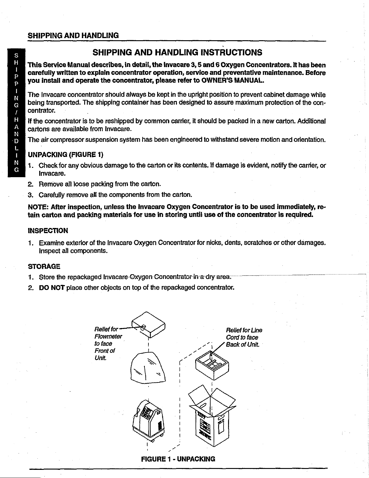
UNPACKING
р
N
1.
G
2.
3.
NOTE:
tain
Service
written
install
Invacare
transported.
the
concentrator
are
air
compressor
Check
Invacare.
Remove
Carefully
for
After
carton
SHIPPING
Manual
and
concentrator
available
(FIGURE
any
ail
remove
inspection,
and
describes,
to
explain
operate
The
is
to
from
suspension
obvious
loose
packing
all
packing
concentrator
the
concentrator,
should
shipping
be
reshipped
Invacare.
system
1)
damage
from
the
components
unless
materials
AND
in
detail,
always
container
to
the
by
common
has
the
the
carton.
Invacare
for
use
be
carton
from
HANDLING
the
Invacare
operation,
please
kept
has
been
in
refer
in
the
been
designed
carrier,
engineered
or
its
the
carton.
Oxygen
storing
INSTRUCTIONS
3, 5 and 6 Oxygen
service
upright
contents.
until
and
to
OWNER'S
position
to
assure
it
should
Concentrator
be
to
withstand
İf
damage
use
of
Concentrators.
preventative
MANUAL.
to
prevent
maximum
.
packed
the
in a new
severe
is
is
to
concentrator
motion
evident,
be
used
It
has
maintenance.
cabinet
protection
damage
of
carton.
notify
immediately,
is
Additional
and
orientation.
the
carrier,
required.
been
Before
while
the
con-
or
re-
INSPECTION
1.
Examine
inspect
STORAGE
1.
Store
the
2,
DO
NOT
exterior
all
components.
repackaged
place
other
of
the
Invacare
Invacare-Oxygen
objects
Relief
Flowmeter
to
face
Front
Unit.
on
for
of
Oxygen
top
Concentrator
Concentrator
of
the
repackaged
| .
for
nicks,
dents,
ina
dry
concentrator.
area.
Relief
Cord
Back
for
to
of
scratches
Line
face
Unit.
or
other
damages.
FIGURE 1 -
UNPACKING
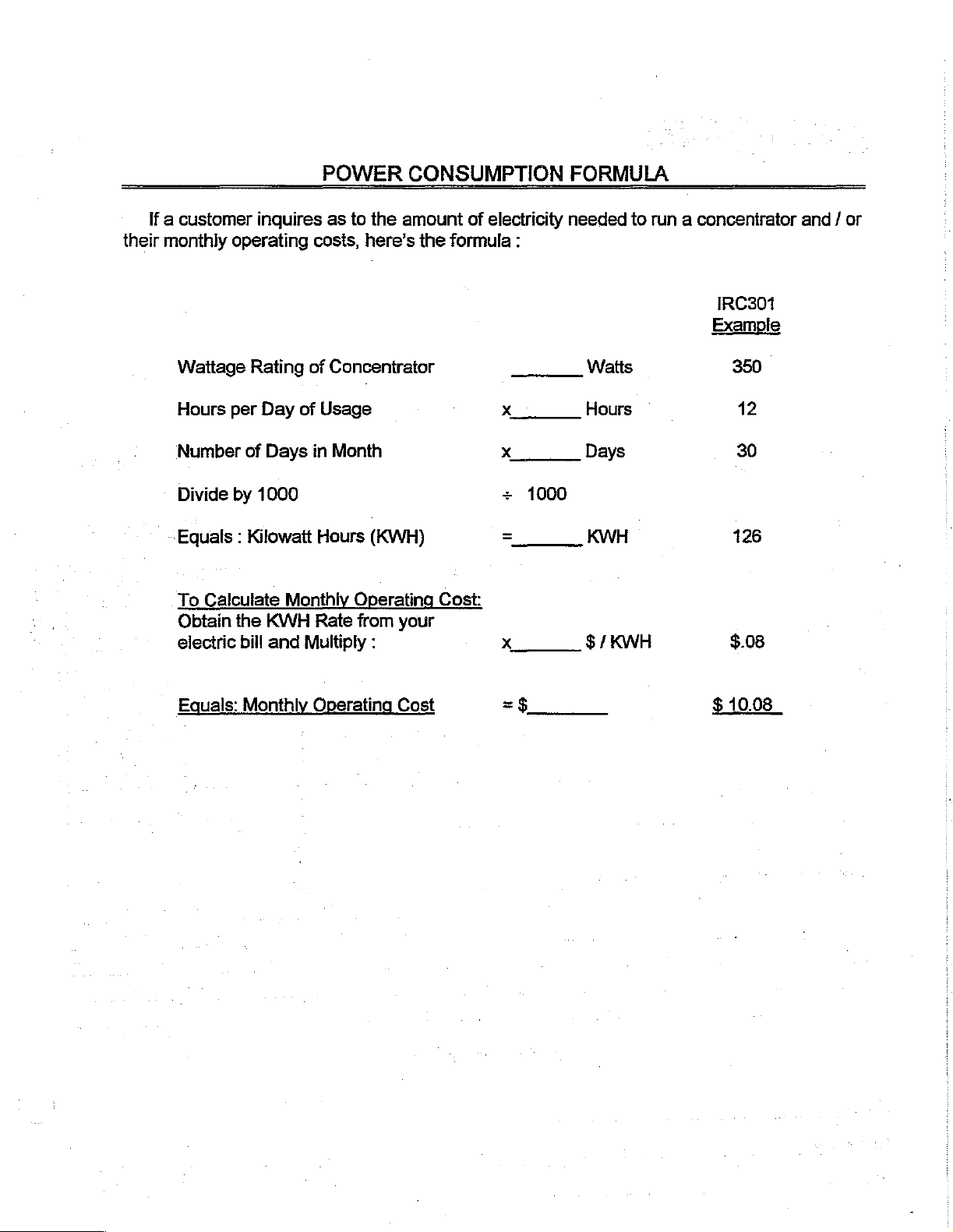
POWER
CONSUMPTION
FORMULA
If a customer
their
monthly
Wattage
Hours
Number
Divide
~Equals : Kilowatt
To
Calculate
Obtain
electric
inquires
operating
Rating
per
of
by
1000
Day
of
of
Days
Monthly
the
KWH
bill
and
Multiply
as
to
the
costs,
in
Hours
here’s
Concentrator
Usage
Month
(KWH)
Operating
Rate
from
:
amount
the
Cost:
your
of
electricity
formula
x
x
+
=
x
:
1000
needed
Watts
Hours
Days
KWH
$/
KWH
to
run a concenirator
IRC301
Example
350
©
12
30
126
$.08
and / or
Equals:
Monthly
Operating
Cost
=$
$
10.08
SEMINAR
FEEDBACK
FORM
In
an
your
1.
2.
3.
4.
Please
effort
to
comments
check
Subject
Contents
Instructor
Service
Format
continually
and
suggestions
the
box
Area
of
Manuals
|
Seminar
Instructor:
Location:
Date:
improve
regarding
which
(PLEASE
the
quality
this
most
Excellent
closely
[1
CHECK
of
this
course.
|Above
Home
O2
APPROPRIATE
seminar,
reflects
we would
your
Avg.|
Systems
BOX)
like
you
judgement
Average
|
to
rate
of
Below
us
and
provide
the
following
Avg. Poor
us
with
areas:
5.
Equipment
Additional
Name:
Company:
Phone:
Comments
and
Materials
and
Suggestions:
Optional
Information
TABLE
OF
CONTENTS
Section
Features
1
.....ceeerenmeecaerenasrrerentenneo
τοι
Installation
Sens
Pneumatic
02
Section
Preventive
4-Way
Compressor
7
カカ
o77gs
Section
7ou//e
Trouble
and
Illustration
Diagram
2
Maintenance
Va ル e
C7ea7n/9
Rebuilding
2679 6 わし
3
Зпоойпа
Shooting
sncataaeraramiseareo
μμ
Sequence
......c.secceeerereeeeasareneescasenecarcorenaaenenasscoracoennerensenaeno
of
ο
Operation...
ΟΡ
Record
ProOceOO
Instructions...
RC
307507
IRC
3LX/5LX/6LX...............
.......sseccsseccessercerssennensssnnersssennnenaceucess
aneaasanarzsasananz
инииинииииииитенивниииние
canta
rre
μμ
carrera
neon
1-1
1-2
1-6
1-10
μμ
rr
rannsarneraonosa
rennes
1-11
2-1
2-4
2-8
2-17
3-1
3-9
Section
Parts
4
Replacement
Section
了
oo
牛人
Mo/ex
Pilot
Venture
Co77ecfo7C カ 7
Valve
Homefill
5
Poppet
Procedures
Replacement
Literature
urnes
ezio vicricrinierii
Kit
0000050007000000
nia
ieini
Instructions
ㅁ ㄷ
000000*400088 ㅁ ㅁ ㄷ ㅁ 0 ㅁ
4-1
to
4-30
cri
nicorinieniseozinisvinionenioni
ri
vzivivene
cesser
040 ㅁ ㄷ
00000 ㅁ 00000 ㅁ 00000 ㅁ … ㅁ
042 ㅁ ㅁ
00000 ㅁ ㄴ 8 ㅠ ㅁ 0 ㅁ ㅠ 04 ㅁ 4008
5-1
5-2
5-9
INVACARE
TECHNICAL
TRAINING
1-800-333-6900
X6697
ELYRIA,
OHIO

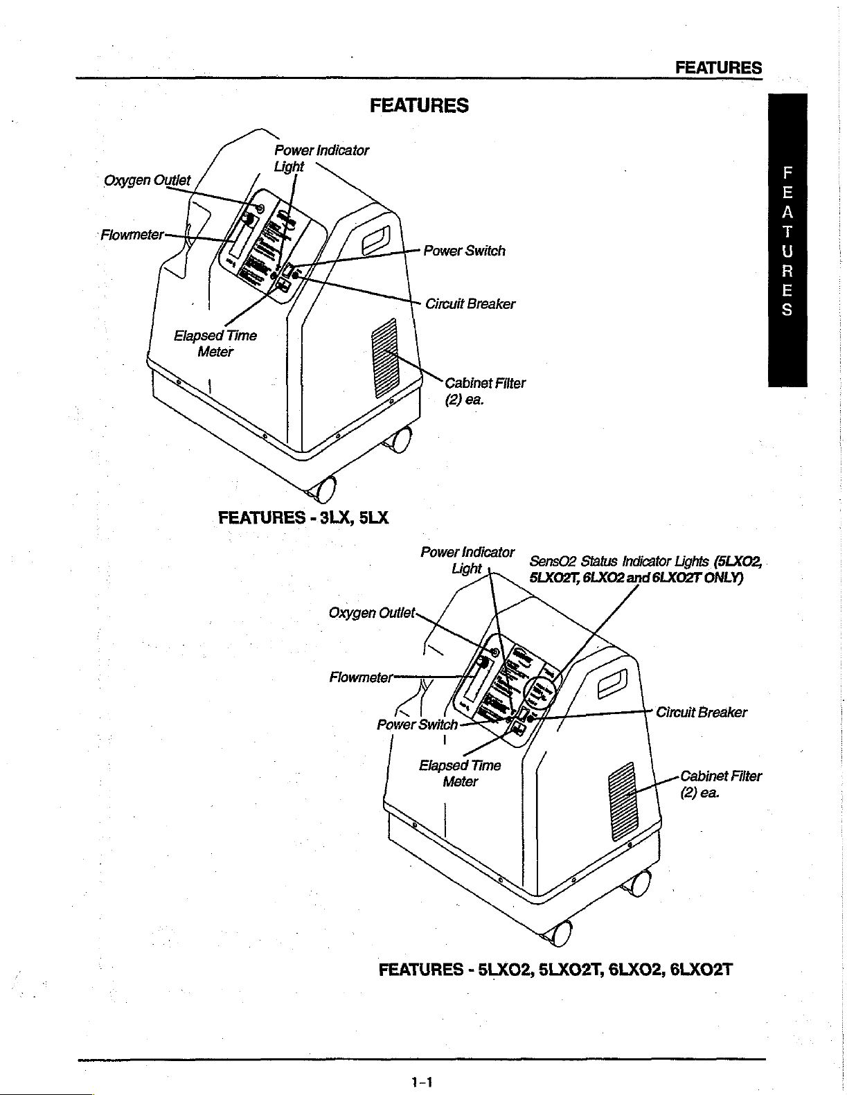
Power
FEATURES
FEATURES
indicator
Oxygen
Outlet
Elapsed
Time
Meter
FEATURES - 3LX,
SLX
Power
Circuit
Cabinet
(2)
Power
Switch
Breaker
Filter
ea.
Indicator
Sens02
5LXO2T,
Status
6LXO2
Indicator
and
Lights
6LXO2T
amacapPmnan
(5LXO2,
ONLY)
Oxygen
Outlet
Power
FEATURES - 5LXO2,
С)
Kl
<
Switch
1
Elapsed
Meter
Time
д
5LXO2T,
6LXO2,
Circuit
Breaker
Cabinet
(2)
ea.
6LXO2T
Filter
1-1
SPECIFICATIONS
MOBILAIRE
Model
MOBILAIRE
OBILAIRE
IRC301 / 501
lit / V
#5:
I
(Νορ,
Ill
/V
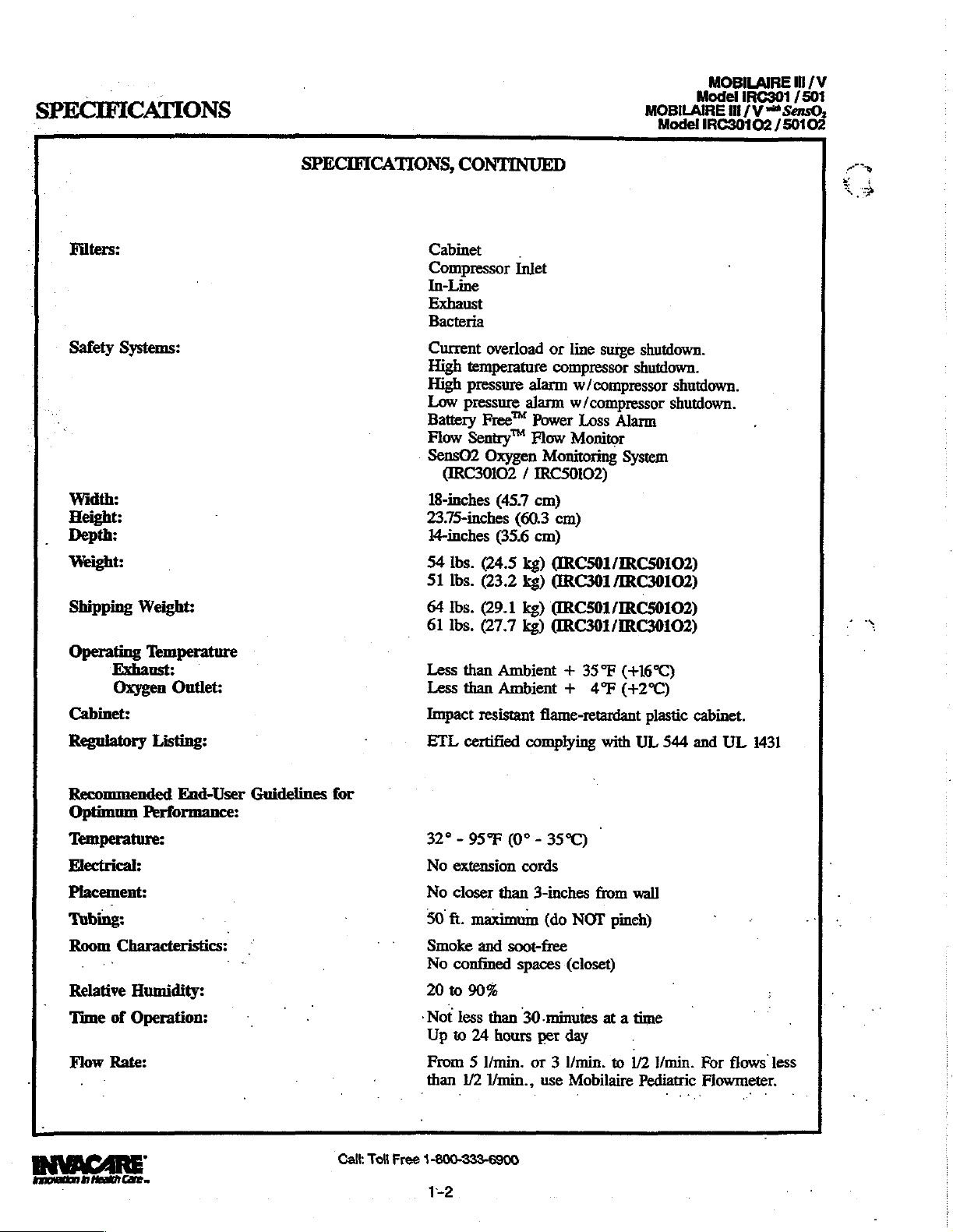
Filters:
Safety
Width:
Height:
Depth:
Weight:
Shipping
Operating
Exhaust:
Oxygen
Cabinet:
Systems:
Weight:
Temperature
Outlet:
SPECIFICATIONS,
CONTINUED
Cabinet
Compressor
In-Line
Exhaust
Bacteria
Current
High
temperature
High
pressure
Low
pressure
Battery
Flow
Sentry™
SensO2 Oxygen
GRC30102 / IRC50102)
18-inches
23.75-inches
14-inches
54
lbs.
51
lbs.
64
lbs.
61
Ibs.
Less
than
Less
than
Impact
.
Inlet
overload
Free™
(45.7
(35.6
(24.5
(23.2
(29.1
(27.7
Ambient + 35°F
Ambient + 4°F
resistant
or
line
compressor
alarm
alarm
w/compressor
Power
Flow
Monitor
Monitoring
cm)
(60.3
cm)
cm)
kg)
(IRC501/IRC50102)
kg)
(IRC301
kg)
(IRC501/IRC50102)
kg)
@RC301/IRC30102)
flame-retardant
w/compressor
surge
Loss
Alarm
System
/IRC30102)
(+16°C)
(+2°C)
shutdown.
shutdown.
shutdown.
shutdown.
plastic
cabinet.
Regulatory
Recommended
Optimum
Listing:
End-User
Performance:
Guidelines
‘Temperature:
Electrical:
Placement:
‘Tubing:
Room
Relative
Time
Flow
Innovation
Characteristics: — *
ーー
Humidity:
of
Operation:
Rate:
.
>
0
Henk
Care
~
ーー
for
Call:
Toll
ETL
32° - 95°F
No
extension
No
closer
50
ft.
Smoke
No
confined
20
to
-Not
less
Up
to
From 5 I/min.
than
Free
1-800-333-6900
1-2
certified
complying
(0° - 35°C)
cords
than
3-inches
maximum
and
soot-free
spaces
90%
than
30-minutes
24
hours
per
or 3 l/min.
1/2
1/min.,
(do
NOT
(closet)
day
use
Mobilaire
with
UL
-
from
wall
pinch)
at a time
to
1/2
Pediatric
544
and
Y/min.
For
Flowmeter.
UL
1431
flows
less
MOBILAIRE
Model
MOBILAIRE
MOBILAIRE
Ill
IRC301 / 501
/V
Ill
/V
“Senso.
Il / “a
senso,
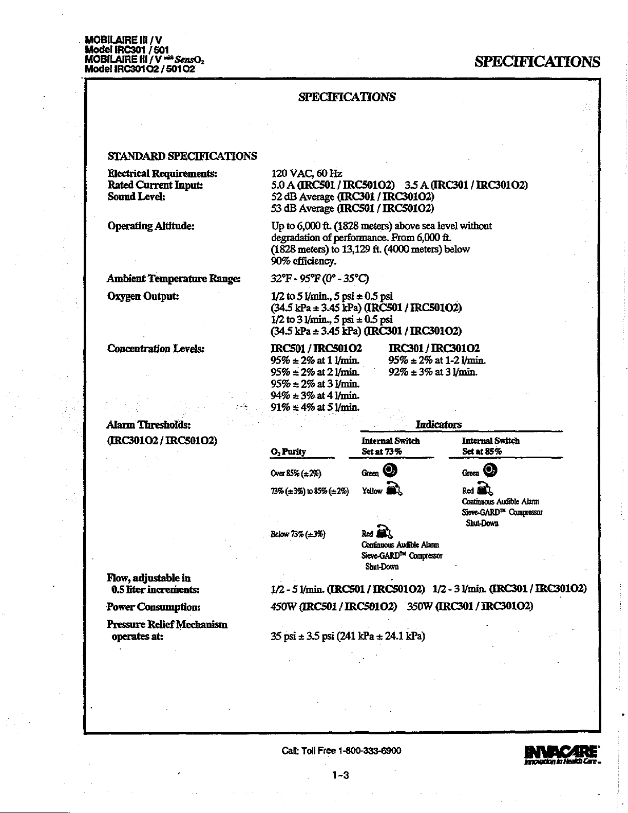
SPECIFICATIONS
SPECIFICATIONS
STANDARD
Electrical
Rated
Current
Sound
Operating
Ambient
Oxygen
Concentration
.
Alarm
Threshoids:
(RC30102 / IRC50102)
SPECIFICATIONS
Requirements:
Input:
Level;
Altitude:
‘Temperature
Output:
.
Levels:
Range:
120
VAC,
5.0 А ERC501
52
dB
Average
53
dB
Average
Up
to
6,000
degradation
(1828
meters)
90%
efficiency.
32°F - 95°F
1/2
to 5 min., 5 psi + 0.5 psi
(34.5
kPa + 3.45
1/2
to 3 /min,, 5 psi + 0.5
(345
kPa + 3.45
IRC501 / IRC50102
95% + 2%
95% + 2%
95% + 2%
94% + 3%
s
91% = 4%
O,
Purity
Over
85% (22%)
60
Hz
/IRC50102)
([RC301 / IRC30102)
(IRCS01 / IRCS0102)
ft.
(1828
meters)
of
performance.
to
13,129
ft.
(4000
(0° - 35°C)
kPa)
(IRC501 / TRCSO102)
psi
kPa)
(RC301 / IRC30102)
at 1 Ymin.
at 2 l/min.
at 3 Ymin.
at 4 Ymin.
at 5 /min.
Internal
Set
at
Green
©
3.5
A(IRC301 / IRC30102)
above
sea
level
without
From
6,000
ft.
meters)
IRC301 / IRC30102
95% + 2%
92% + 3%
Switch
73%
below
.
at
1-2
Yenin.
at 3 /min.
.
Indicators
Internal
Set
Green
at
85%
©
Switch
Flow,
adjustable
0.5
liter
increments:
Power
Consumption:
Pressure
operates
Relief
in
Mechanism
at:
73%
(238)
085%
(22%)
Below
73%
(23%)
1/2 - 5
min.
(ERCS01 / IRC50102)
450W
(ARC501 / IRC59102)
35
psi + 3.5
Call:
Toll
psi
Free
1-3
Yellow
に
Red
m
Continuous
Sieve-GARD™
Shut-Down
-
(241
kPa + 24.1
1-800-333-6900
Audible
Alarm:
Compressor
350%
kPa)
Red
m
Continuous
Sieve-GARD™
1/2 - 3
/min.
(RC301 / IRC30102)
Audible
Alarm
Compressor
Shut-Dowa
ŒRC301 / IRC30102)
Innovation
in
Hesich
Care
—
SPECIFICATIONS
S
P
E
C
1
F
i
C
A
T
1
O
N
S
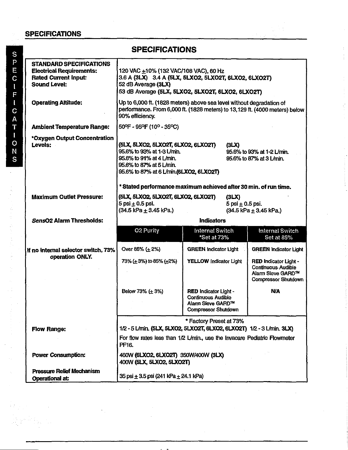
STANDARD
Electrical
Rated
Sound
Operating
Ambient
*Oxygen
Levels:
Maximum
SPECIFICATIONS
Requirements:
Current
Level:
Input:
Altitude:
Temperature
Output
Concentration
Outlet
Range:
Pressure:
SPECIFICATIONS
120
VAC
+10%
3.6 A (3LX)
52
dB
Average
53
dB
Up
to
6,000
performance.
90%
efficiency.
50°F - 95°F
@LX,
5LXO2,
95.6%
to
95.6%
to
95.6%
to
95.6%
to
*
Stated
(LX,
5LXO2,
5
psi + 0.5
(34.5
kPa + 3.45
3.4 A
Average
ft.
(1828
From
(10° - 35°C)
5LXO2T,
93%
at
91%
at 4 Limin.
87%
at 5 Limin.
87%
at 6 Umin.(6LXO2,
performance
5LXOZT,
psi.
(132
(5LX,
(3LX)
(SLX,
6,000
1-3
Umin.
kPa.)
VAC/108
5LXO2,
5LXO2,
meters)
ft.
(1828
6LXO2,
maximum
6LXO2,
VAC),
5LXO2T,
5LXO2T,
above
sea
meters)
GLXO2T)
6LX02T)
achieved
6LXO2T)
60
Hz
6LX02,
6LXO2,
level
without
to
13,129
(3LX)
95.6%
95.6%
after
(SLX)
5
psi+
(34.5
6LXO2T)
6LXO2T)
degradation
ft.
(4000
to
93%
at
to
87%
at 3 Limin.
30
min.
of
0.5
psi.
kPa + 3.45
meters)
1-2
L/min.
run
time.
kPa.)
of
below
SensO2
lf
no
Flow
Power
Pressure
Operational
Alarm
internal
selector
operation
Range:
Consumption:
Relief
Thresholds:
switch,
ONLY.
Mechanism
at:
02
Purity
Over
85%
(+
73%
73%
(+
Below
1/2 - 5
For
flow
PF16.
460W
400W
35
psi + 3.5
2%)
3%)
to
85%
73%
(+
3%)
Umin.
(LX,
rates
less
(6LXO2,
(SLX,
5LX02,
psi
(42%)
SLXO2,
than
6LXO2T)
5LX02T)
(241
kPa + 24.1
1/2
350W/400W
Indicators
Internal
*Set
GREEN
YELLOW
RED
Indicator
Continuous
Alarm
Sieve
Compressor
*
Factory
5LXOZT,
L/min.,
kPa)
Switch
at
73%
Indicator
Indicator
Light
Audible
GARD™
Shutdown
Preset
6LXO2,
use
the
(LX)
Light
Light
-
at
73%
6LXO2T)
Invacare
Internal
Set
GREEN
RED
Continuous.
Alarm
Compressor
12 - 3
Pediatric
Indicator
indicator
Sieve
N/A
L/min.
Flowmeter
Switch
at
85%
Light
Audible
GARD™
Shutdown
3LX)
Light
-
SPECIFICATIONS
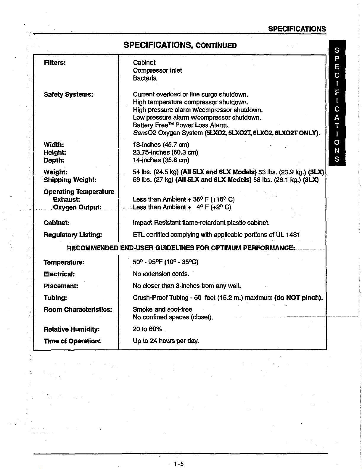
Filters:
Safety
Width:
Height:
Depth:
Weight:
‘Shipping
Operating
Exhaust:
„Oxygen
Systems:
Weight:
Temperature
Output:
SPECIFICATIONS,
Cabinet
Compressor
Bacteria
Current
High
High
Low
Battery
SensO2
18-inches
23.75-inches
14-inches
54
59
Less
|.
Less
overload
temperature
pressure
pressure
Free™
Oxygen
(45.7
(35.6
Ibs.
(24.5
Ibs.
(27
kg)
than
Ambient + 359 F (+169
than
Ambient + 49F
inlet
or
compressor
alarm
alarm
Power
System
cm)
(60.3
cm)
kg)
(All
(All
.
CONTINUED
line
surge
shutdown.
shutdown.
w/compressor
w/compressor
Loss
Alarm.
(5LX02,
cm)
SLX
and
6LX
SLX
and
6LX
(+29
shutdown.
shutdown.
5LXO2T,
Models)
Models)
C)
C)
6LX02,
53
lbs.
58
Ibs.
6LXO02T
(23.9
(26.1
kg.)
ONLY).
kg.)
(3LX)
(SLX)
5
E
A
F
|
©
A
Es
|
o
N
S
Cabinet:
Regulatory
Temperature:
Electrical:
Placement:
Tubing: Crush-Proof
Room
Relative
Time
of
Listing:
RECOMMENDED
Characteristics:
Humidity:
Operation:
Impact
ETL
END-USER
50° - 95°F
No
extension
No
closer
Smoke
No
confined
20
to
Up
to
Resistant
certified
60%
24
complying
GUIDELINES
(10° - 35°C)
cords.
than
Tubing - 50
and
soot-free
spaces
.
hours
flame-retardant
with
applicable
FOR
OPTIMUM
3-inches
per
from
feet
(closet).
day.
any
plastic
wall.
(15.2
cabinet.
portions
PERFORMANCE:.
m.)
maximum
of
一 一 一
UL
(do
1431
NOT
一
pinch).
一
1-5
INSTALLATION
SEQUENCE
AND
OPERATION
OF
pMOBILAIRE
Е
Sa,
Y
Y
INSTALLATION
When
your
1.
ifthe
unit
before
2.
The
IRC301/501
Connect
flow
will
off.
3.
With
the
checks
4.
Connect
per
specifications
SEQUENCE
new
operating.
power
power
the
cord
Mobilaire
has
been
cord
begin
immediately.
cord
Battery
to
receptacle
OF
OPERATION
INSTALLATION
Model
IRC30102 | IRC50102 — Serial
Model
Model
concentrator
in
below-freezing
will
need
to
to
receptacle
unplugged,
Free“
Alarm
and
after
30-40
IRC301 — Serial
IRC501 — Serial
attives,
temperatures,
be
turned
and
tum
Set
flow
of
press
On/Off
Circuit.
turn
on
concentrator. 3 BEEPS
minutes
running
AND
it
should
on
for a few
on
concentrator.
the
Mobilaire
switch
Tum
switch
time.
SEQUENCE
Numbers
Numbers
be
checked
allow
seconds
HI
to
the
“off.”
OF
Numbers
90E
to
90F
to
for
it
to
warm
to
charge
Tum
flow
to 3 /min.
“on”
position.
on
startup.
OPERATION
93D
to
Present
Present
Present
proper
operating
up
for
30
the
Battery
control
and
knob
Mobilaire V to 5 l/min.
An
audible
Check
conditions.
minutes
at
Free™
counterclockwise
alarm
the
oxygen
room
temperature
Alarm
Circuit.
and
Tum
will
sound.
concentration
unit
This
Apply
120
VAC
circuit
(P.C.)
Room
air
enters
the
wobble
*Units
As
increased
20° F (-6.7°
sorption
is
necessary
balance
valve
the
air.
The
to 5 PSI
‘tient.
The
and
P.C.
time.between
position
On
the
allows
cycle
pistons
built
material. A restrictor
entering
into
room
oxygen
(34.4
i
electrical
board
when
IRC501 / 50102, a 2-way
high
at a higher
via
the
power
board.
the
compressor
in
the
prior
to
90K
will
pressure
C)
for the
not
kPa),
energization
cycles
de-energized.
purity
creates
as
the
air
adsorption
the
top
of
air. A filter
being
used
enters
electronics
is
dependent
oxygen
pressure.
switch
via
compressor
run
at
increased
enters
the
four-way
downstream
process. À small
the
second
is
located
to
purge
an
accurate
of
the
solenoid
when
the
on'altitude
*
pressure
to
enter
the
The
2-way
energizes
the
cabinet
to a pressure
22
PSI
temperature, a heat
bed.
at
the
is
channeled
flow-measuring
pressure
same
valve
the
filter,
of
(151.5
kPa).
solenoid
of
the
sieve
amount
The
nitrogen
exhaust-end
into a storage
valve
is
accomplished
set
point
and
flow
equalization
bed
from
will
close
compressor
air
inlet
filter,
20
PSI
(137.72
exchanger
valve.
It
is
bed
causes
of
relatively
removed
of the
valve
tank.
device,
of
rate. A "spring
valve
the
just
20
PSIG + 3
opens
top.
This
after
flows
the
motor,
hour
meter,
and
sound
muffler.
kPa),
then
is
utilized
then
channeled
pressure
is
every
additional
shift
to
build
pure
oxygen
purged
from
to
muffle
the
The
pressurized
through a bacterial
10
to
14
(137.72
in
the
just
valve
prior
of
the
kPa + 51.32
to
pressure
4-way
cooling
put
through
to
lower
to a sieve
up
enters a storage
the
nitrogen
seconds
allows
the
shift
The
the
bed
inside
bed
through
exhaust
oxygen
filter
by
it
to
of
the
allows
valve.
fan
air
an
temperature
the
is
and
the
kPa)
return
4-way
the
and
the
printed
is
compressed
in-line
filter.
by
containing
sieve
tank with
the
regulated
out
pressure
is
bed
the
bed
four-way
as
it
enters
down
to'the e pa
sensor
reached.
to
its
original
valve.
to
start
by
ad-
which
the
|
The
This
its
INVACARE
Innovation
in
Health
Cate
=
Cal
Toll
Free
1-800-333-6900
1-6
EN
IRC30102
Model
/50102
*
INSTALLATION
SEOUENCE
OF
AND
OPERATION
If
power
is
interrupted,
IRC301’s
trical
for
SensO,
Technical
The
tween
gen
As
of
the
Electric
to
over
oxygen
the
are
lated
concentration
and
system
your
oxygen
sensor
the
zirconia,
released
to
malfunctions.
convenience.
OXGYEN
Description
being
these
components
mounted
oxygen
zirconia
current
300°
C.
ions
are
only
from
the
oxygen
IRC501’s
enters
disk.
“reading”
INSTALLATION
the
Battery
are
equipped
The
‘Troubleshooting
SENSOR
produced
on
the
flowing
Oxygen
attracted
oxygen
the
oxygen
concentration.
TECHNOLOGY
by
is a tee
the
printed
sensor
to
the
top
molecules
to
the
ions
can pass
ions
is
calculated.
AND
SEOUENCE
Free™
alarm
with a diagnostic
the
concentrator flows
fitting
that
directs a small
circuit
board.
housing,
electrode
it
passes
electrode
on
and
The
and
top
of
on
through.
oxygen
electrons
the
the
will
sound a short
alarm
Guide
explains
CERAMIC
out
of
flow
through a screen
through
disk
bottom
Once
molecules
travel
the
pick-up
of
the
oxygen
retum
to
the
OF
OPERATION,
“beep,”
system
the
ZIRCONIA
the
product
of
oxygen
and
zirconia
extra
electrons
zirconia
ions
reach
to
the
PC
board
CONTINUED
with a long
that
signals
alarm
tank
through a precision
contacts
disk
to
disk.
the
air.
The
where
if
system’s
SENSOR
and
into
the
the
bottom
and
become
Because
bottom
number
they
are
pause,
intermittently.
the
system’s
signals
and
the
flowmeter.
orifice
electrode
of
electrode,
“counted”
mounted
electrode
oxygen
the
crystal
of
electrons
pressure
reasons
In-line
to
heats
ions.
structure
the
extra
is
directly
and
the
All
or
elec-
in
detail
be-
the
oxy-
on
the
top
the
disk
These
of
electrons
re-
oxygen
A
micro-processor
compares
PC
dible
Operating
Once
-
gin
After 5 minutes,
“If
the
for a maximum
tors,
If
the
vate,
“
When
ing
tinuously
Shut-Down
the
the
board.
Signals
indicators,
Sequence
the
power
to
produce
oxygen
such
as
oxygen
depending
oxygen
falls
below
and a yellow
red
LED / Alarm / Shut-Down
on
the
PC
signal
to
clinical
outside
and/or
switch
clinical
when
level
of
30
low
voltage,
level
upon
of
system
has
acceptable
oxygen
is
not
above
minutes
high
is
not
above
the
position
been
concentration
85% + 2%
and
LED
mode
will
activate.
board
acceptable
the
shut-down.
purity
85% + 2%
from
altitude,
85% + 2%
is
above
the
will
If
contains
clinical
turned
oxygen
start-up
of the
alarm
illuminate. If the
the
mode
software
limits
acceptable
to
ON,
the
before
exceeds
85% + 2%
after
‘the
to
reach
or
age
of
within
indicator
85% + 2%,
indicator
oxygen
purity
will
áctivate.
Call:
Tol!
that
SensO2
activating.
the
the
switch.
the
is
oxygen
Free
that
interprets
have
been
selected
limits
generate
circuit
will
No
LED’s
the
green
first 5 minutes,
85% + 2%
machine
first
30
All
sensor
in
the
73%
purity
falls
below
1-800-333-6900
1-7
LED's
before
will
affect
minutes,
units
measures
mode,
falls
85% + 2%
o
the
signal
with
the
responses
LED
are
oxygen
below
in
wait 5 minutes
will
illuminate
will
illuminate.
will
activating
the
time
the
oxygen
preset
at
purity
the
oxygen
73% + 3%
with
being
received
indicator
the
form
for
for
remain
off.
an
alarm.
required
level
the
factory
every
sensor
the
indicator
from
the
switch
mounted
of
lighted
the
at
The
Environmental
to
alarm
at
10
measures
the
red
LED’s,
concentrator
least 5 minutes.
system
reach
85% + 2%.
sequence
73% + 3%.
minutes.
purity
LED / Alarm
switch
set
innovation
sensor.
will
on
au-
fo
wait
fac-
will
It
the
be-
acti-
If a read-
con-
/
at
85%,
in
Health
-
:
Care
=

INSTALLATION/SEQUENCE
OF
OPERATION
INSTALLATION / SEQUENCE
MODEL
INSTALLATION / VERIFICATION
When
1.
2.
3.
4.
5.
SEQUENCE
Applying
printed
Room
compressed
Serial
As
ture
the
.
sieve
the
back
valve
your
new
Ifthe
unit
has
mately
The
Connect
begin
Tum
Unplug
sound.
30
concentrator
power
immediately.
unit
off.
the
This
OFF.
Connect
Check
cord
the
OF
120
circuit
air
enters
by
No.
"97K"
increased
by
20° F (6.7°
adsorption
bed
which
top
of
the
from
the
to
muffle
minutes)
power
oxygen
VAC
(P.C.)
pressure
maierial. A restrictor
second
bed
the
3LX
Invacare
been
cord
confirms
to
OPERATION
via
the
the
or
C)
is
necessary
through
sound
concentrator
in
below-freezing
before
will
need
to
outlet
Set
flow
cord
proper
outlet
concentration
the
power
board.
compressor
wobble
21
PSI
creates
before
bed
of
and
to
and tum
rate
and
and
turn
pistons
(144.79
the
for
with
the
four-way
the
MODELS
OF
BATTERY
arrives,
temperatures,
operating.
be
tumed
of
the
press
operation
switch.
via
increased
air
the
the
exhaust
on
the
Invacare 3 to 3
On/Off
on.
concentrator.
per
specifications
energizes
the
cabinet
in
the
kPa)
AFTER
enters
downstream
adsorption
balance
valve
as
5LX,5LX02,
FREE™
it
should
for 4 to 5 seconds
concentrator
L/min.,
switch
of
the
Battery
the
filter,
compressor
Serial
5LXO2T,
POWER
be
checked
allow
it
to
on.
Tum
Invacare
to
the
ON
Free™
Unit
will
sound 3 BEEPS
after
30-40
compressor
compressor
to a pressure
No.
"97K".
temperature, a heat
the.4-way
of
the
valve.
sieve
itis
process. A small
entering a storage
into
room
air. A muftler
it
exits the
concentrator.
OF
OPERATION
6LXO2,
LOSS
for
proper
to
warm
up
charge
flow contro!
position.
exchanger
then
bed
tank.
the
knob
5 to 5 L/min.
An
Power
inlet
causes
amount
Loss
minutes
motor,
filter,
of
20
is
channeled
of
The
nitrogen
is
located
6LXO2T
ALARM
operating
to
room
temperature
Battery
hour
pressure
Free!
Power
counterclockwise
and
the
Invacare
intermittent
Alarm.
audible alarm
Turn
on startup.
running
and
PSI
utilized
relatively
time.
meter,
cooling
sound
(137.72
to
lower
to a sieve
to
build
pure
removed
at
the
exhaust
muffler.
conditions.
(approxi-
Loss
Alam.
and
flow
will
6 to 6 L/min.
will
On/Off
kPa)
the
bed
up
oxygen
is
switch
fan
and
the
The
air
BEFORE
tempera-
containing
inside
the.
enters
exhausted
end
of
the
is
A
e
MA
S
E
Q
U
E
N
Cc
E
ο
F
ο)
P
'
E
R
A
T
i
о
N
The
oxygen
regulated
down
filter, a check
The
electrical
and
P.C.
board
Serial
between
On
the
the
close
No.
“97K"
cycles
the
5LX/5LX02/5LXO2T/6LX02/6LXO2T,
shift
of
the
top.
This
just
after
not
being
used
to 5 PSI
valve
and
activation
electronics
or
21 + 3 PSI
is
dependent
4-way
additional
the
valve.
pressure
shift
(34.4
out
to
of
the
when
This
of
the
to
exhaust
kPa),
enters
the
patient.
4-way
on
valve
the
pressure
(144.79 + 51.32
altitude,
allows
allows
4-way
highly
the
valve.
is
channeled
an
accurate
is
accomplished
set
flow
rate
a
P.E.
concentrated
bed
to
into
the
flow-measuring
every 8 to
point
of
20 + 3
kPa)
AFTER
and
internal
or
Pressure
oxygen
start
its
cycle
storage
tank.
device,
21
seconds
PSI
(137.72 + 51.32
Serial
environmental
No.
Equalization
to
enter
at a higher
The
pressurized
fiows
through a bacterial
by
the
"97K"
is
reached.
factors.
valve
the
just
exhausted
pressure.
pressure
kPa)
opens
The
P.E.
oxygen
sensor
BEFORE
The
time
-
just prior
bed
valve
to
from
will
is
INSTALLATION / SEQUENCE
OF
OPERATION
INSTALLATION / SEQUENCE
If
main
power
intermittently.
or
electrical
reasons
SENSO2
Technical
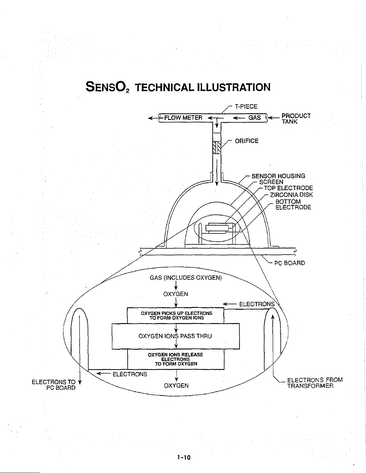
The
oxygen
In-line
orifice
As
SS
Electric
contact
are
zirconia,
electrons
electrons
95
are
E
Q
A
U
sensor.
E
switch
N
с
the
Ε
o
Operating
F
Once
ο
begin
P
minutes.
E
R
After 5 minutes,
Α
T
If
|
wait
ο
mental
N
reach
between
to
the
oxygen
current flowing
the
attracted
“counted”
microprocessor
It
mounted
form
the
producing
the
oxygen
for a maximum
factors
85%
is
lost,
All
units
systems
in
detail
for
OXGYEN
Description
being
these
the
oxygen
enters
electrode
to
the
only
oxygen
are
released
is
directly
and
on
compares
on
of
lighted
Sequence
power
switch
if
level
such
+2%.
clinically
the
the
LEDs,
is
the
Battery
are
equipped
malfunction.
your
convenience.
SENSOR
produced
components
sensor
the
through a metal
of
electrode
ions
from
related
oxygen
the
the
the
PC
oxygen
not
of
30
as
by
mounted
sensor,
the
disk
on
can
pass
the
to
the
concentration
P.C.
board
signal
board.
audible
has
been
acceptable
purity
above
minutes
low
voltage,
Free”
Power
with a diagnostic
The
Troubleshooting
TECHNOLOGY
the
concentrator
is a tee
it
passes
and
pick-up
the
bottom
through.
oxygen
oxygen
contains
to
clinically
Signals
indicators,
turned
exceeds
85% + 2%
from
high
fitting
on a printed
through a screen
film
resistor
When
ions
concentration.
acceptable
outside
ON,
oxygen
after
start-up
altitude,
OF
Loss
Alarm
alarm
CERAMIC
flows
that
directs a small
circuit
heats
extra
electrons
of
the
zirconia
the
and
oxygen
"reading"
software
and/or
the
before
85% + 2%
the
to
is
of
the
system
SensO,
activating.
first 5 minutes,
reach
or
age
OPERATION,
will
sound a short
system
Guide
out
of
board.
the
to
disk.
oxygen
molecules
The
calculated.
that
interprets
limits
clinically
shut-down.
circuit
the
GREEN
85% + 2%
of
the
that
explains
É
ZIRCONIA
the
product
and
contacts
disk
in
become
Because
ions
electrons
that
have
acceptable
will
wait 5 minutes
No
LEDs
machine
signals
the
flow
excess
oxygen
reach
the
retum
travel
the
signal
been
LEDs
LED
will
before
CONTINUED
"beep",
if
the
pneumatic
alarm
SENSOR
tank
of
oxygen
the
of
300°C.
of
the
bottom
to
to
selected
limits
will
will
illuminate.
remain
activating
will
affect
system
and
into
through a precision
sensing
ions.
These
crystal
electrode,
the
air.
the
PC
being
generate
for
the
illuminate
off.
the
with a long
pressure
signals
the
flowmeter.
disk.
Oxygen
board
received
with
molecules
oxygen
structure
the
The
number
where
from
the
indicator
responses
concentrator
for
at
The
system
an
alarm.
time
Environ-
required
pause,
and
ions
of
the
extra
of
they
the
in
to
least
5
will
to
If
the
oxygen
sequence
factory
When
If a reading
oxygen
below
and
at
73% + 3%.
oxygen
sensor
73% + 3%
it
is
set
85% + 2%.
level
is
will
activate,
concentration
falls
below
measures
the
at
85%,
the
not
above
depending
85% + 2%
purity
RED
RED
85% + 2%
upon
is
above
and
continuously
LED/Alarm/Shut-Down
LED/Alarm/Shut-Down
within
the
position
85% + 2%,
the
alarm
and a yellow
the
first
of
the
the
sensor
indicator
mode
mode
30
minutes,
indicator
measures
is
in
the
LED
will
activate.
will
the
switch.
oxygen
73% mode
will
illuminate.
lf
activate
oxygen
or
the
if
the
concentration
All
units
purity
every
no
switch
If
the
oxygen
selector
oxygen
are
preset
10
is
present,
switch
purity
alarm
at
minutes.
purity
falls
is
present
falls
below
the
the
SENSO,
TECHNICAL
<
FLOW
METER
ILLUSTRATION
T-PIECE
“τρ
<—
ORIFICE
GAS
SENSOR
SCREEN
Ve
HOUSING
TOP
ELECTRODE
ZIRCONIA
BOTTOM
ELECTRODE
PRODUCT
DISK
©
一
一
一
ELECTRONS
PC
BOARD
TO
GAS
(INCLUDES
OXYGEN
OXYGEN
©
ELECTRONS
TO
OXYGEN
OXYGEN
TO
PICKS
FORM
IONS
IONS
ELECTRONS
FORM
OXYGEN
+
UP
OXYGEN
Y
OXYGEN
,
ELECTRONS
IONS
PASS
RELEASE
OXYGEN)
THRU
<—
ELECTRONS
6
ELECTRONS
TRANSFORMER
EROM
NEUMATIC
P
DIAGRAM
G
MOBILAIRE
Model
MOBILAIRE
Model
ill / V
IRC30102
IRC301 / 501
Ill / V
“#*
SersO,
50102
/
OXYGEN
ENRICHED
PRODUCT
TEST
POINT
BACTERIA
FILTER
FLOWMETER
|
#2
FLOW
RESTRICTOR
‘OPTIONAL
OXYGEN
SENSOR
INPUT
À
=
„7
PNEUMATIC
92
.
[|]
RE
SENSO!
SENSOR
'
DIAGRAM
pc.
ВО
TEST
PRODUCT
BOARD
A
COLUMN
POINT
$
TANK
SIEVE
#1
VALVES
CHECK
ge
LA
501
ONLY
RE.
VALVE
SIEVE
COLUMN
.
CROSS-OVER
ASSEMBLY - -
AIR
INLET
イイ
FILTER
ASS'Y
|
RESONATOR
PARTICLE
GROSS
FILTER
>
AIR
COMPRESSOR
RELIEF
VALVE
.
HEAT
SOLENOID
===
EXCHANGER
VALVE
・ ㆍ
-
'
FIUER
os
j
dnnovetion
hh
Heatth
Care
Call:
Toll
Free
1-800-333-6900
~
1-1
1
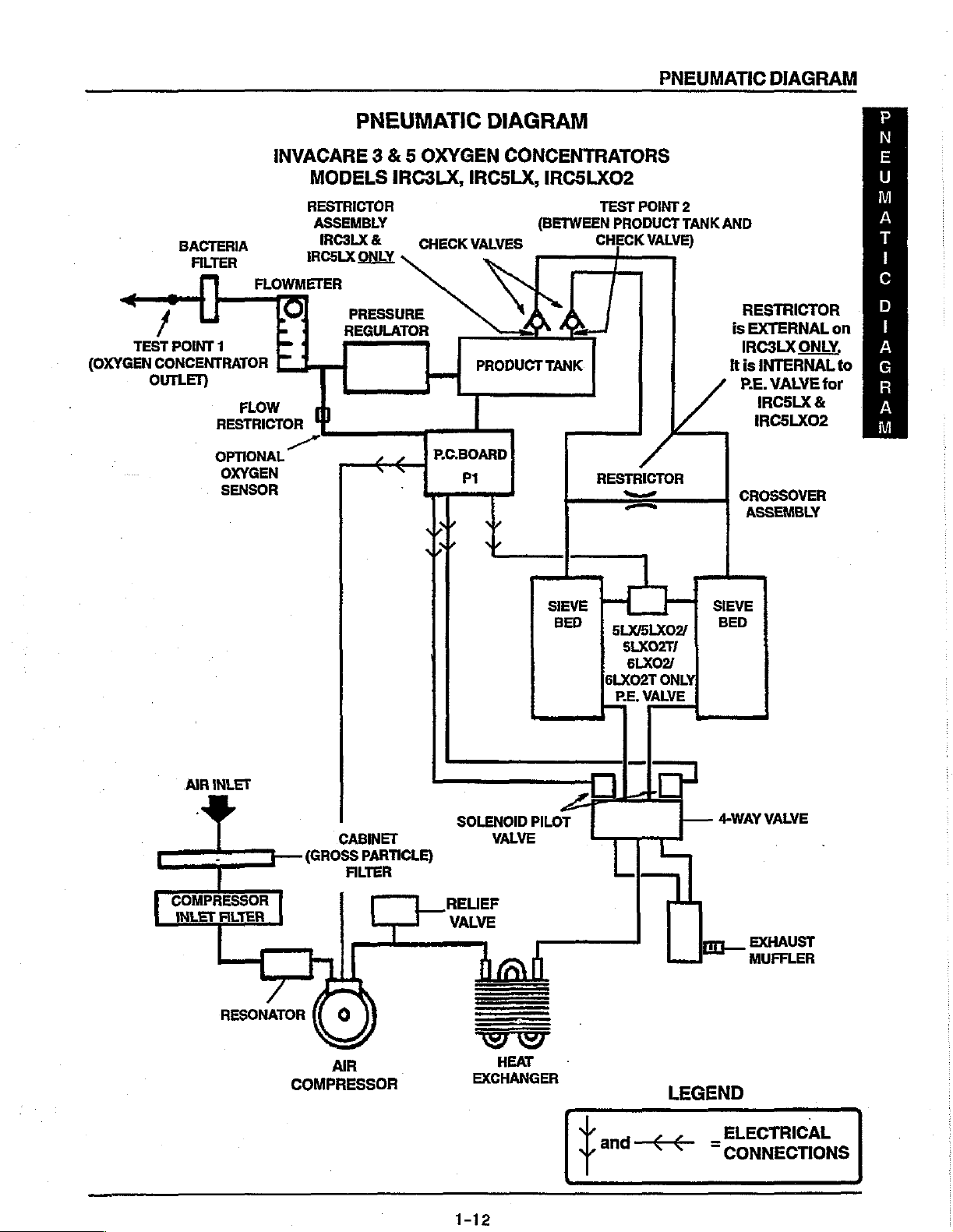
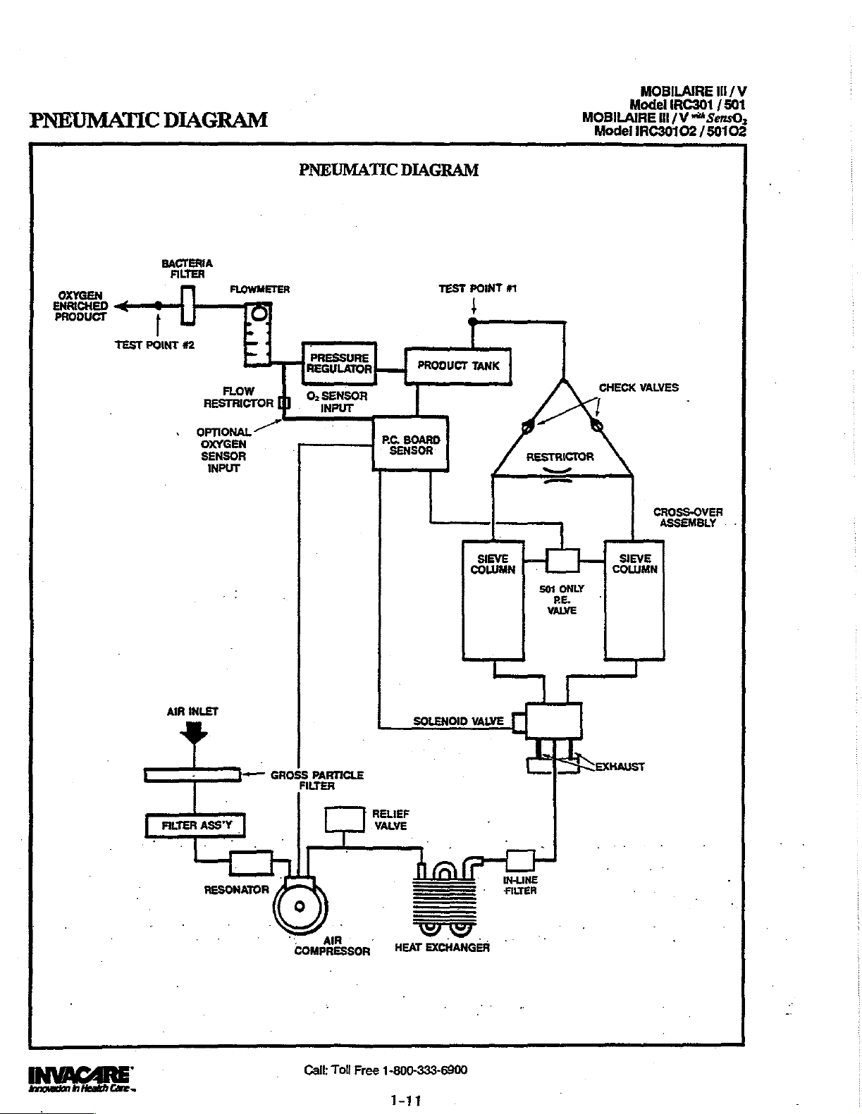
PNEUMATIC
DIAGRAM
/
TEST
(OXYGEN
CONCENTRATOR
OUTLET)
BACTERI
FILTER
POINT
OPTIONAL
.
INVACARE 3 & 5 OXYGEN
A
FLOWMETER
1
|
FLOW
RESTRICTOR
OXYGEN
SENSOR
PNEUMATIC
MODELS
RESTRICTOR
ASSEMBLY
IRC3LX
IRC5LX
Τη
&
ONLY
PRESSURE
REGULATOR
|
IRC3LX,
CHECK
个
P.C.BOARD
ANS
-
DIAGRAM
CONCENTRATORS
IRC5LX。
(BETWEEN
VALVES
PRODUCT
PI
IRC5LXO2
TEST
POINT
2
TANK
PRODUCT
CHECK
TANK
VALVE)
上
一
SIEVE
BED
RESTRICTOR
=
デー
sxsLxo | BED
SLXO2T/
6LXO2/
6LXO2T
РЕ.
МАМЕ
ONLY!
AND
RESTRICTOR
is
EXTERNAL
IRC3LX
It
is
INTERNAL
P.E.
IRCSLX
IRCSLXO2
CROSSOVER
ASSEMBLY
SIEVE
ONLY,
VALVE
for
&
on
to
P
N
E
Y
M
A
T
I
o
D
I
A
G
R
A
M
|
SOLENOID
|
RELIEF
VALVE
a
VALVE
di
HEAT
EXCHANGER
I
~
2
CH
VALVE
4-WAY
i
|—
πι
EXHAUST
MUFFLER
PILOT
L
IP
LEGEND
_
ELECTRICAL
Fora
<<
=conNECTIONS
AIR
INLET
y
-
CABINET
(Goss
CET]
—
RESONATOR
COMPRESSOR
PARTICLE)
FILTER
AR

INVACARE
RESPIRATORY
©
OXYGEN
Invacare
Some
-IRC
-IRC
-IRC3LX
-IRC5LX
-IRC5LXO, 5 Liter
In
the
componenis.
Item
Item
produces
of
them
301
501
3
5
3
5
following
#1
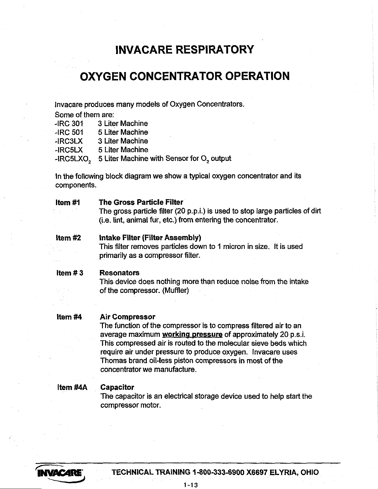
The
The
(i.e.
#2
Intake
This
primarily
are:
Liter
Liter
Liter
Liter
block
Gross
gross
lint,
filter
many
Machine
Machine
Machine
Machine
Machine
Filter
CONCENTRATOR
models
diagram
Particle
particle
animal
(Filter
removes
as a compressor
of
Oxygen
with
Sensor
we
show a typical
Filter
filter
(20
fur,
etc.)
from
Assembly)
particles
filter.
Concentrators.
for
O,
output
oxygen
p.p.i.)
is
entering
down
to 1 micron
used
the
OPERATION
concentrator
to
stop
large
concentrator.
in
size.
particles
It
and
is
used
its
of
dirt
Item # 3
item
#4
Item
#4A
Resonators
This
device
of
the
compressor.
Air
Compressor
The
function
average
This
require
Thomas
concentrator
maximum
compressed
air
under pressure
brand
Capacitor
The
capacitor
compressor
does
nothing
of
the
working
air
oil-less
we
manufacture.
is
an
motor.
more
(Muffler)
compressor
pressure
is
routed
to
produce
piston
electrical
compressors
storage
than
is
to
the
reduce
to
compress
of
approximately
molecular
oxygen.
device
noise
filtered
sieve
Invacare
in
most
used
from
beds
of
the
to
help
the
air
20
uses
intake
to
an
p.s.i.
which
start
the
INVACARE
TECHNICAL
TRAINING
4-800-333-6900
1-13
X6697
ELYRIA,
OHIO

Нет
#5
Item
#6
Item
#7
Item
#8
Item
#9 P.E.
Heat
Exchanger
The
heat
and
transfers
Inline
The
the
Filter
inline
Numatics
Solenoid
A
four-way
air
to
the
Sieve
Spring
material
Beds
loaded
through
Valve
This
item
the
sieve
exchanger
it
to
(IRC
filter
is a .3
Solenoid
Valve
valve
sieve
manufactured
bed
cannisters
strips
the
nitrogen
canisters.
is
only
used
bed
with
removes
the
airstream
301/
507
micron
Valve.
and
from
on 5 liter
oxygen
the
supplied
Only)
filtering
by
directs
filled
the
with
room
machines.
before
heat
produced
by
device
Numatics
exhaust
molecular
air
but
allows
the
pressurizing
by
the
fan.
that
is
Inc..
air
out
Sieve
oxygen
Its
function
the
compression
used
to
protect
that
directs
of
the
sieve
material. This
to
pass
`
is
to
pressurize
cycle
starts.
compressed
beds.
Item
item
item
item
Item
#10
#11
#12
#13
#14
Restrictor
An
orifice
the
Sieve
flow
Check
Check
oxygen
tank.
P.C.
This
with a hole
Cannister
through
Valves
Valves
generated
Board
device
information
valves
Product
A
for
valve
and
Tank
cannister
delivery
out
of
Regulator
The
adjustable
5
p.s.i.
outlet
diameter
and
thus
the
Sieve
are
Beds.
one-way
by
the
Sensor
measures
and
if
there
of
approximately
uses
are
pressure
it
in
problems
to a patient.
the
flowmeter.
pressure
pressure.
of
.042”.
determines
flow
devices.
Sieve
the
circuit
Beds
in
the
related
1-1/2
The
larger
regulator
reduces
This
the
They
goes
product
to
help
to
liters
volume
the
volume
component
rate
at
which
are
used
to
and
stays
tank , and
decide
when
pressure,
which
the
more
input
pressure
back-pressures
room
air
to
insure
in
the
product
takes
to
shift
this
etc.
stores
oxygen
stable
the
to a constant
can
that
the
flow
E
TECHNICAL
TRAINING
1-800-333-6900
X6697
ELYRIA,
OHIO

Item
ltem
#15
#16
Flowmeter
The
flowmeter
oxygen
Bacteria
This
the
dispensed
Filter
patient
is a gas
Filter
consist
oxygen
measuring
to a patient.
of
a .3
micron
stream.
device
element.
which
It
is
the
controls
final
the
filter
amount
used
in
of
INVACARE
TECHNICAL
TRAINING
1-800-333-6900
1-15
X6697
ELYRIA,
OHIO


PREVENTIVE
MAINTENANCE
]
PROCEDURE
2
[IA
QHOO
HOIVdLN
ヨ
H
ヨ
ヨ
ONVN
ONOS
ヨ
1NIVI
NbDAXO
"ON
TVIH
ヨ
S
Ou!
"ON
TACON
AA
A
AOS]
E<
-ZH-UZAZOU
ヨ
AILN
ヨ
HVOVANI
ヨ
人 ハ
ヨ
Hd
ЗНАМОЙ
SRIDOVANI
na
PURA
6-1
SM
АНЗАЯ
—
10
9960
pesde|3
eses
ploo9y
(she
16191
ljeulqeo
4(>
94001
ueelo
eled
UONSJHUSoUOO
Mold
(ZOSNZS
"UILUA
LNOHLIM
PEqUOSEIS
ueBAXO
SLINN)
хэецо
49949
SIN
ヨ
LVd
N
ヨ
ヨル
14616
1
B
ヨ
OAmVnNNY
6907
76004 12042
Jell
elueloeg
ATIVONNY
@98IdeH
(Блежы
лебиецохз
зещаео
зеен
гов4еы
ивею
uohelueouoo
(ST3dOW
ロ
ヨ
HIO
ue6Axo
<OSM
ヨ
H
49849,
ヨ
SV
S)
39411
SHTOH
JosseJduio
39IUI
10SSe』dUJ0O
000'02
jo
doz
998Id9H
人 H
piinqey
ヨ A ヨ
"Z0x19
"X19
‘x1£
ISTOXA
JIJnA
*
101
SheUx
STEGONM
OUJ-UJ
ヨ
ODPJdOL
89BIdeH
119)
«uoocao
(120x719
‘ZOX19
120X19
2-1


CABINET
|
PROCEDURE
1
INVACARE
PROCEDURE
TO
PREVENT
ELECTRICAL
1.
Unpiug
2.
Remove
8.
Lift
NOTE:
4.
To
unit.
the
cabinet
When
re-install
3LX,
1 - REMOVING
ELECTRICAL
OUTLET
the
eight
(8)
straight
required,
cabinet,
REPAIR / REPLACEMENT
INVACARE - 5LX/SLXO2/SLXO2T
BEFORE
mounting
up.
vacuum
reverse
CABINET
SHOCK,
SERVICING.
screws
inside
STEPS
that
of
the
2-3.
(FIGURE
CAUTION
ALWAYS
secure
cabinet
1)
DISCONNECT
cabinet
and
GUIDE
AND
INVACARE - 6LXO2/6LXO2T
CONCENTRATOR
assembly
exposed
Cabinet
to
the
foam
Assembly
base
assembly.
insulation.
FROM
AMZ-Wro
Base
Mounting
FIGURE 1 -
Screws
REMOVING
2-2
(8
each)
CABINET
Assembly
INVACARE
innovation
in
Health
°
Care
ra
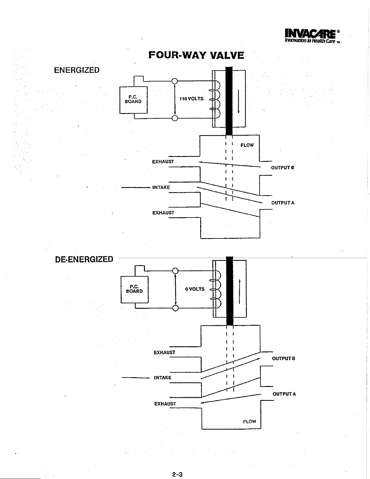
ENERGIZED
[
Р.С.
BOARD
FOUR-WAY
EXHAUST
q
Tel
INTAKE
EXHAUST
0
一
110
一
一
0
VOLTS
VALVE
$
4
<
OA
—
iii
A
Tr
1
LI
Ut
AAA
FLOW
|]
OUTPUT
OUTPUTA
B
DE-ENERGIZED
PC.
BOARD
Lo
EXHAUST
INTAKE
一
EXHAUST
ονοιτς
一
一
στ
|
中
<
-
AT
4
ia
pa
Va
rt
11
a
1
i
OUTPUTA
FLOW

INVACARE’
Innovation
in
Health
Care
sa
SOLENOID/SPRING
KIT
NO.
2001177
-
UPGRADE
2
3
À
5
&
NOTE:
The
Mobilaire V (IRCS01
REMOVING
CAPSULE
“Tum
Oxygen
Remove
Monet
2.
to
3.
KIT
one
()
Se
Coi
(9
One
one
Done
wo
Ciamps
a
Sleeve
O-Rings
Six
(6)
following
instructions
e
THE
OFF
power
Concentrator.
asen
Remove
the
the
support
Remove
the
INCLUDES
Hose
11-inches
onde
Cap.
JF
Solenoid
i
(8)
O-Rings
are
apply
and
IRC501
SPOOL/SLEEVE
and
UNPLUG
5/8-inch
o ho
four (4)
screws
frame.
clear
tubing
THE
pring
needed - two
WARNING
truss
bass
that
KIT
Solenoid/Spring
of
FOLLOWING:
τς
ος
used
to
Case
{2}
to
Mobilaire
rade.
9
upg
AND
the
cord
from the
・
head
screws
assembly
that
secure
is
connected
the
i
in
are
lll
(RC301)
SOLENOID
‘nat
the
control
to
Solenoid
μα.
conjunction
-
spares.
and
Mobilaire
-
secure
panel
the
bottom
‘
Kit
and
Installation
Assembly
Servicing
Instructions
and
Capsule.
3
Remove
plate
4.
Remove
5.
6
Gently
7.
Inspect
are
The
set.
that
special
interchanging
8.
Push
you
NOTE: A soft
9.
body.
MOT
the
two
to
the
valve
the
spool/sleeve
Remove
two
endplate
remove
spoot
present,
assembly.
spool
Spools
only
can
than
ed
tap
Now
twist
replace
and
are
one
(1)
precautions
the
sleeve
firmly
dowel
the
outside
with
hammer
the
sleeve
the
m
(2)
screws
body
and remove
(2)
screws
assembly
spool
for
steeve
not
of
grip
using a 3mm
spring.
and
out
of
nicks,
scratches
entire
WARNING
assembly
interchangeable.
assembly
be
taken
spools.
out
of
either
the
sleeve.
(nylon,
diameter
(nylon,
partially
sleeve
as
you
|
o
unos
(25
mm
Allen)
the
from
the
endplate
Allen
valve
body.
or
wear.
assembly
valve
is a precision
be
wood,
out
on
It
cleaned
to
prevent
end
of
etc.)
of
the
wood
or
of
the
are
removing
Me
alano
the
that
secure
plate.
of
wrench.
If
any
spool/sleeve
or
is
at a time
slightly
sleeve
matched
recommended
the
accidental
valve
body
smaller
can
rubber)
valve
it
to
body.
from
|
rien
the
of
these
or
that
be
gently
the
the
until
us-
valve
ton
4.
Move
the
control
NOTE:
This
will
capsule
5.
Unscrew
spool/sleeve
SPOOL/SLEEVE
(FIGURE
N ° Sloan
1.
Remove
secure
cap)
2.
Remove
1)
to
End
the
the
n
the two
the
the
the
Plate
panel
to the
make
access
easier.
inlet
filter
and
GENERAL
solenoid
spool/sleeve.
solenoid
before
solenoid
rr
(2)
6/32 x Finch
capsule
capsule
|
Spring
|
一
CC
.
right-side
to
the
spoolsieeve
disassembling
capsule.
CLEANING
..
assembly.
fiat
(which
include
and
gasket
Spoot
p
|
-
一
FIGURE 1 —
of
the
concentrator
and
solenoid
the
INSTRUCTIONS
not
head
screws
coil
Sleeve
|
ELEK
0
ings
Needed
that
and
ry
end
Valve
CLEANING
10
to
a.
b.
©.
to
You
ings/cautions
valve/spool
Numatics® - is a Registered
Body
.
THE
Piate
SPOOL/SLEEVE
en
Apply
Numatics®
spool
by
rubbing
Allow a few
white)
and
Apply
the
RUB.
Let
dry
MUST
adhere
assembly.
o
ee
yes?
Valve
Cleaner
the
lands
minutes
then
Numatics Valve
”
for
wipe
off
then wipe
tothe
listed
off
seston;
when
5
Solenoid
olenoid
the
7
(Coil)
ASSEMBLY
iy
(P/N
briskly
with a soft
cleaner
the
residue.
Cleaner
again.
all
residue
manufacturer's
cleaning
Trademark
Ca
Capsule
р
x
{End Cap)
0137-135)
to
dry
(will
DO
from
the
the
of
Numatics,
to
the
clean
cloth.
tum
NOT
spool.
war
T
solenoid
-
3-Inch
Flat
Screws
Inc.
Head
2-4


d.
After
time,
e
After
and
possibly
11.
To
clean
DO
NOT
the
sleeve
a.
Remove
plastic
from
DO
NOT
assembly
Pletely
b.
After
assembly,
the
‘agitate
all
You
MUST
ings/cautions.
valve/spool
©.
After
and
possibly
DO
NOT
clean
d.
the
Replace
the
valve
let
the
let
the
use a hard/sharp
knittng
the
use
as
removed
the
sleeve
the
contaminates.
cleaner
the
spool
spool
has
dry,
blow
in
the
sleeve
O-rings
needle
grooves
out any
left
assembly.
the
O-ring
Numatics
residue
from
O-rings
soak
the
has
soaked
sleeve
in
soak
spool
assembly:
WARNING
Valve
from
the
have
sleeve
WARNING
adhere
to
the
listed
assembly.
the
sleeve
let
use
dry,
inside
blow
left
any
the
has
out
in
the
sleeve.
WARNING
cleaning
of
the
O-rings
has
in acetone.
been
removed
contaminates
with
WARNING
instrument
from
the
(or
equivalent)
on
the
Cleaner
the
inner
been
assembly
in
acetone
the
acetone
acetone
when
been
removed
any
contaminates
tools
sleeve.
on
the
been
wiped
off
from
the
compressed
sleeve
sleeve
cleaner
diameter
removed
manufacturer's
cleaning
(brushes,
sieeve
or
that
may
assembly
to
remove
assembly.
to
clean
cannot
of
from
in
acetone.
for a few
to
completely
the
from
the
or
pads,
assembly
the
second
acetone
moisture
air
damage
using
the
the
sleeve
be
com-
the
sleeve.
the
sleeve
minutes,
remove
ls
warn-
solenoid
acetone
moisture
etc.)
by
.
a
O-rings
After
.
to
REINSTALLING
SOLENOID
1.
2.
3
4
REPLACING
OF
CHANGER
NOTE:
NOTE:
1.
Do
the
2
3.
4.
5
THE
CAPSULE
Reinstall
ing
“plate
Piug
the
Instali
tubber
assembly.
Reinstall
THE
Remove
the
aluminum
Route
heat
valve
Reinstall
Reinstall
Attach
the
sure
the
solenoid
The
but
When
either a screwdriver
middle
not
heat
exchanger
endplate
that
the
and
in
the
white
assembiy
the
new
coll
gasket
is
the
inlet
THE
4-WAY
VALVE
(FIGURE
8-inch
oniy
change
removing
the
hose
connector
overtighten
and
if
the
new
assembly
the
clear
control
cabinet
assembly
SPOOL/SLEEVE
(FIGURE
on
spring
center:
connector
positioned
HOSE
2)
stainless
that
the
is
positioned
of
the
into
to
the
and new end
filter.
properly
FROM
ASSEMBLY
steel
the
hose
the
clamps
or a 1/4-inch
runs
from
of
the
4-way
the
spool/sleeve
THE
WARNING
the
clamps
.
The
heat
PVC
middie
with
to
to
the
exchanger
hose
connector
the
overtightened,
tt-inch
to
the
and
secure
tubing
panel.
AND
properly
before
making
on the
MIDDLE
THE
must
residue
the
socket
heat
exchanger
assembly.
secure
is
tubing
spring
on
of
the
assembly.
NEW
assembly
assembiy.
solenoid
HEAT
the hoses
made
will
the
clamps.
1)
spool/sleeve
spool.
solenoid
cap
TO
spring
if
from
the
valve
that
the
with
adjustable
bottom
base
in
the
assembling
sure
that
CONNECTOR
EX-
be
replaced
is
apparent.
hoses,
use
wrench.
to
-
of
soft
collapse.
from
the
4-way
flowmeter.
mak-
end-
”
the
to
assembly
NOTE:
ff a kit
O-rings
spares.
12.
To
replace the
sleeve
DO
NOT
damage
13
Gently
14.
To
replace
the
valve
15.
The
sleeve
16.
Insertion
rectly locate
Form
grooves.
is
used,
but
only
spool,
assembly.
tilt
the
may
result.
turning
spool,
the
sleeve,
body.
should
of
the
the
No.
91-170
there
six
carefully
WARNING
spool
or
insert
gently
be
roughly
end
plates
assembly
899
Cleveland
(P/N
will
be a total
(6)
are
needed.
align
the
force
it
it
into
sleeve.
push/twist
centered
and
bumper/spacers
in
the
valve
St.
«
2001187)
spool.
into
the
in
body.
PO.
of
eight
Two
the
(8)
(2)
are
with
the
sleeve
as
sleeve
into
the
valve
body.
will
cor-
INVACARE’
Innovation
Box
4028
Rev.
©
in
Elyria,
Ohio
9/92
Health
44036-2125
FIGURE 2 —
MIDDLE
ASSEMBLY
Carew
U.S.A.
REPLACING
CONNECTOR
TO
«
Phone
THE
THE
HOSE
OF
THE
HEAT
EXCHANGER
14800)
333-5900
FROM
4-WAY
THE
VALVE
2-5
PROCEDURE
2
PREVENTIVE
MAINTENANCE
PROCEDURE
TO
<mav
MOZrP2MAZ—~prps
PREVENT
DISCONNECT
TRICAL
NOTE:
cally
maintenance
places
nance
The
of
additional
factory-trained
preventive
Power
preventive
trator.
Cabinet
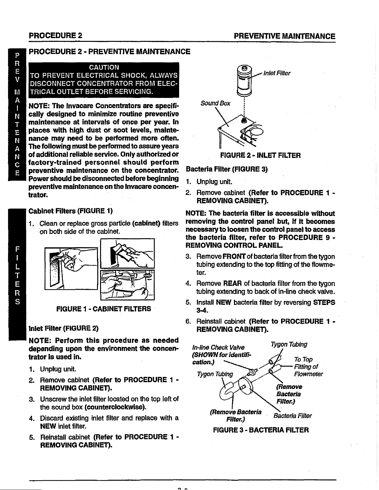
1.
OUTLET
The
designed
with
may
following
should
maintenance
Filters
Clean
‘on
or
both
2 - PREVENTIVE
CAUTION
ELECTRICAL
CONCENTRATOR
BEFORE
Invacare
at
high
need
must
reliable
maintenance
be
Concentrators
to
minimize
intervals
dust
to
be
be
performed
service.
personnel
disconnected
(FIGURE
replace
side
of
gross
the
cabinet.
SHOCK,
SERVICING.
routine
of
once
or
soot
performed
Only
should
on
the
on
the
1)
particle
MAINTENANCE
ALWAYS
FROM
levels,
to
assure
ELEC-
are
specifi-
preventive
per
year.
mainte-
more
authorized
perform
concentrator.
before
Invacare
beginning
concen-
(cabinet)
In
often.
years
or
filters
Sound
Bacteria
1.
Unplug
2.
Remove
REMOVING
NOTE:
removing
necessary
the
REMOVING
3.
The
bacteria
Remove
tubing
ter.
©
==)
그
Box
$
FIGURE 2 -
Filter
(FIGURE
unit.
cabinet
CABINET).
bacteria
the
control
to
loosen
filter,
CONTROL
FRONT
extending
Inlet
INLET
3)
(Refer
filter
panel
the
control
refer
PANEL.
of
bacteria
to
the
Filter
FILTER
to
PROCEDURE
is
accessible
but,
panel
to
PROCEDURE
filter
top
fitting
if it
from
of
the
without
becomes
to
access
the
tygon
flowme-
1
9
-
-
FIGURE 1 -
iniet
Filter
NOTE:
depending
trator
1.
2.
3.
4.
5.
Perform
is
used
Unplug
Remove
REMOVING
Unscrew
the
sound
Discard
NEW
Reinstall
REMOVING
(FIGURE
upon
in.
unit.
cabinet
the
box
existing
inlet
filter.
cabinet
CABINET
2)
this
procedure
the
environment
(Refer
CABINET).
inlet
filter
(counterclockwise).
inlet
(Refer
CABINET).
FILTERS
to
PROCEDURE
located
filter
and
to
PROCEDURE
as
the
on
the
replace
needed
concen-
1
top
left
with
1
-
of
a
-
4.
Remove
tubing
5.
Install
3-4.
6.
Reinstall
REMOVING
In-line
(SHOWN
cation.)
Tygon
REAR
extending
NEW
bacteria
cabinet
CABINET).
Check
Valve
for
identifi-
Tubing
(Rem
a
FIGURE 3 -
of
bacieria
to
back
filter
(Refer
一
人
BACTERIA
filter
from
of
in-line
by
to
Tygon
check
reversing
PROCEDURE
Tubing
To
Top
Fitting
Flowmeter
(Remove
Bacteria
Filter.)
Bacteria
Filter
FILTER
the
tygon
vaive.
STEPS
of
1 -

PREVENTIVE
MAINTENANCE
PROCEDURE
2
PROCEDURE
Exhaust
(FIGURE
NOTE:
20,000
can
the
1.
2.
3.
4.
5.
6.
7.
8.
9.
Exhaust
Muffler
4)
The
hr.
performed
be
environment
Unplug
Remove
REMOVING
Remove
manifold
canister
Disconnect
top
of
canister.
Remove
and
remove
Unscrew
muffler
Inspect
intemal
Replace
a).
plugged
Install
b).
good
Install
reversing
.
Reinstall
REMOVING
Tubing
2
(continued) - PREVENTIVE
Canister/Exhaust
following
intervals
the
unit,
_
cabinet
CABINET).
ty-wraps
the
exhaust
(canister).
the
mounting
muffler
(counterclockwise)
located
muffler
filtration
muffler
or
NEW
condition.
NEW/re-install
STEPS
x
cabinet
CABINET).
should
although
needed
as
concentrator
(Refer
that
tubing
exhaust
screw
canister.
muffler
the
on
canister
do
and
canister
restricted.
exhaust
existing
3-5.
(Refer
be
these
depending
PROCEDURE
to
secure
to
top
fittings
hoses
from
rear
canister.
restriction
for
the
of
one
muffler
muffler
to
PROCEDURE
MAINTENANCE
Muffler
performed
procedures
exposed
is
」
4-way
of
fittings
from
of
soundbox
exhaust
the
following:
muffler
and
canister
if
canister
Ty-wraps
at © Unplug
upon
to.
:
-
1
Valve
muffler, 4 Remove
on
the
of
if
in
is
by
1 -
P
Cleaning
a
2.
00
3.
Remove
DURE
exchanger
Reinstall
5
DURE 8 -
6.
Reinstall
REMOVING
FIGURE 5 -
Finned
unit
damage
001
g,
8
CLEANING
Heat
.
CAUTION
fins
cleaning,
heat
exchanger
REPLACING
-
excessive
fins
using
exchanger
heat
REPLACING
cabinet
(Refer
CABINET).
Exchanger
PROCEDURE
to
ET).
exchanger
heat
of
or
reinstalling.
(Refer
HEAT
dirt
build-up
compressed
(Refer
HEAT
to
PROCEDURE
FINNED
HEAT
(FIGURE
to
EXCHANGER).
air.
to
EXCHANGER).
Heat
Fins
Compressed
Air
Dirt
EXCHANGER
5)
when
PROCE-
on
heat
PROCE-
Exchanger
(Use
Clean
to
Buildup).
1
1
-
-
R
Е
M
BM
A
!
à
Ε
EN
[ie
N
E
H
E
A
T
E
X
С
H
A
AX
G
E
R
(From
4-way
Manifold.)
Exhaust
Canister
Exhaust
Muffler
Muffler
FIGURE 4 -
Valve
EXHAUST
EXHAUST
T
DA
A
.
MUFFLER
MUFFLER
Mounting
Rear
Sound
CANISTER/
Screw
of
Box
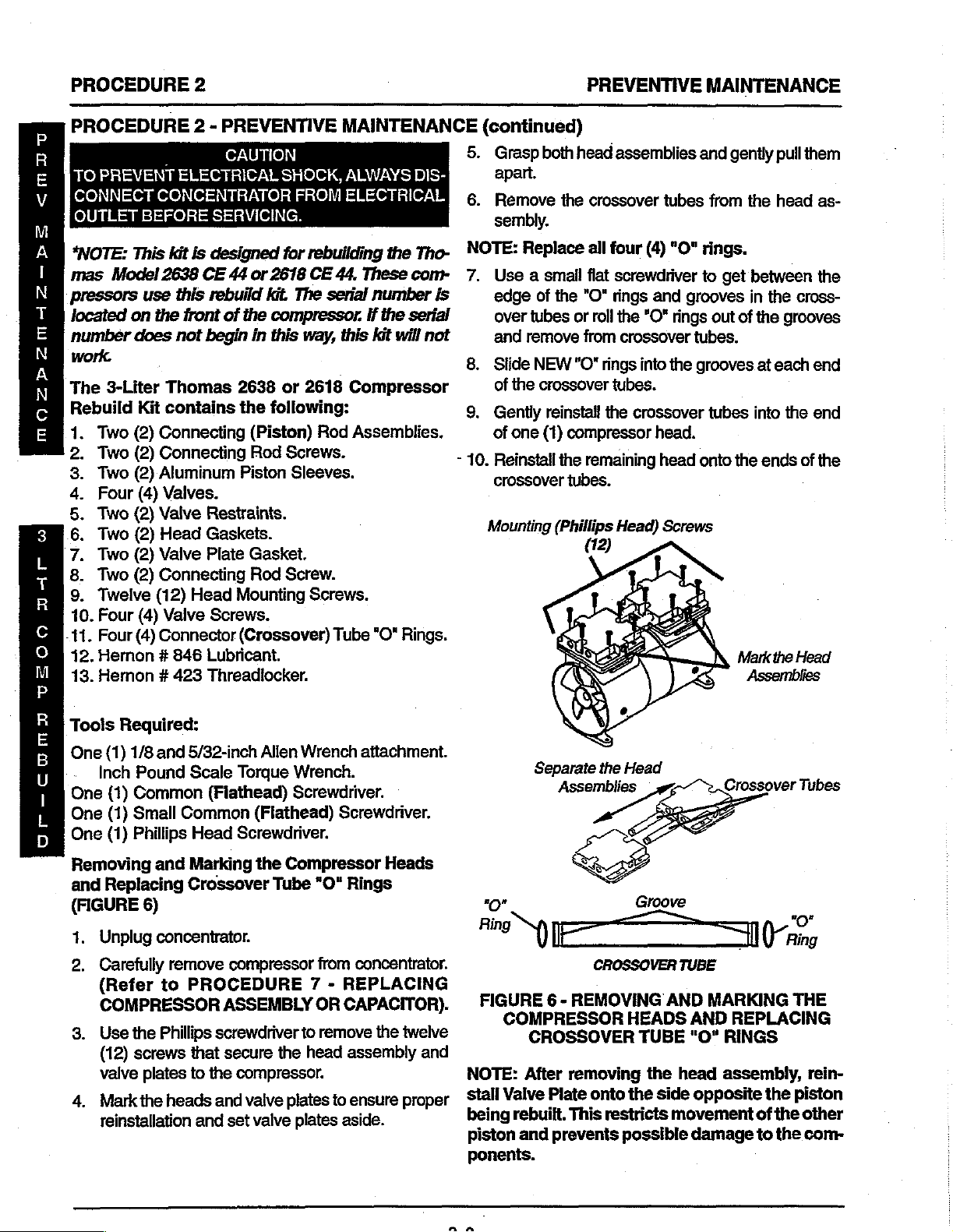
PROCEDURE
PROCEDURE
TO
PREVENT
(の 9 | ο Μο
<MITU
OUTLET
“NOTE:
ps
mas
Model
pressors
located
number
2 - PREVENTIVE
i
ELECTRICAL
οί
BEFORE
This
kit
is
2638
use
this
on
the
front
does
not
2
CAUTION
SHOCK,
ο
MER
SERVICING.
designed
CE
44
or
rebuild
of
the
begin
in
for
2618
kit.
The
compressor.
this
way,
MAINTENANCE
ALWAYS
rebuilding
CE
44,
serial
These
number
If
this
the
the
kit
DIS-
Tho-
conr
is
serial
will
not
(continued)
5.
Grasp
6.
apart.
Remove
sembly.
NOTE:
7.
Use a small
edge
over
and
both
head
the
Replace
of
the
tubes
or
remove
PREVENTIVE
assemblies
crossover
all
four
flat
screwdriver
"O"
rings
roll
from
tubes
(4)
"O"
and
the
"O*
rings
crossover
MAINTENANCE
and
gently
from
the
rings.
to
get
between
grooves
tubes.
out
in
of
the
the
pull
them
head
as-
the
cross-
grooves
work.
The
3-Liter
Rebuild
mOZPZzmM-AZ-
3
L
T
R
σ
о
M
P
R
同
B
U
|
上
D
Two
>
Two
Two
ON
Four
Two
Two
Two
Two
.
Twelve
CONOR
10.
Four
-11.
Four
12.
Hernon # 846
13.
Heron # 423
Toois
One
(1)
Inch
(1)
One
One
(1)
One
(1)
Removing
and
Replacing
(FIGURE
Thomas
Kit
contains
(2)
Connecting
(2)
Connecting
(2)
Aluminum
(4)
Valves.
(2)
Valve
(2)
Head
(2)
Valve
(2)
Connecting
(12)
Head
(4)
Valve
(4)
Connector
Required:
1/8
and
5/32-inch
Pound
Scale
Common
Small
Phillips
and
6)
Common
Head
Marking
Crossover
Restraints.
Gaskets.
Plate
Screws.
Lubricant.
Threadlocker.
(Fiathead)
2638
or
2618
the
following:
(Piston)
Rod
Piston
Gasket.
Rod
Mounting
(Crossover)
Allen
Torque
Rod
Screws.
Sleeves.
Screw.
Screws.
Tube
Wrench
Wrench.
Screwdriver.
(Fiathead)
Screwdriver.
the
Compressor
Tube
"O"
Compressor
Assemblies.
"O"
Rings.
attachment.
Screwdriver.
Heads
Rings
8.
Slide
of
the
9.
Gently
of
one
-
10.
Reinstall
crossover
Mounting
"О"
Bi
NEW
"O"
rings
crossover
reinstall
(1)
the
. on
(Phillips
Separate
tubes.
the
compressor
remaining
tubes.
Head)
the
Assemblies
E
ES
into
the
grooves
crossover
head.
head
Head
Groove
tubes
onto
Screws
=
at
each
end
into
the
end
the
ends
of
the
Crossover
Tubes
o
1.
Unpug
2.
Carefully
(Refer
concentrato:
remove
to
PROCEDURE
COMPRESSOR
a
Phillips
the
Use
8.
(12)
screws
valve
plates
4.
Markthe
reinstallation
that
to
heads
and
compressor
ASSEMBLY
screwdriver
secure
the
and
、
the
compressor.
valve
set
valve
from
concentrator.
7 - REPLACING
CAPACITOR).
OR
remove
to
head
plates
the
assembly
to
ensure
plates aside.
twelve
and
NOTE:
proper
_Stall
being
piston
ponents.
"Nea
REMOVING
-
FIGURE
6
COMPRESSOR
CROSSOVER
After
removing
Valve
Plate
rebuilt.
and
This
prevents
CROSSOVER
AND
HEADS
TUBE
the
onto
the
side
restricts
possible
movement
TUBE
MARKING
REPLACING
AND
RINGS
"O"
head
assembly,
opposite
of
damage
to
THE
the
piston
the
other
the
com-
rein-
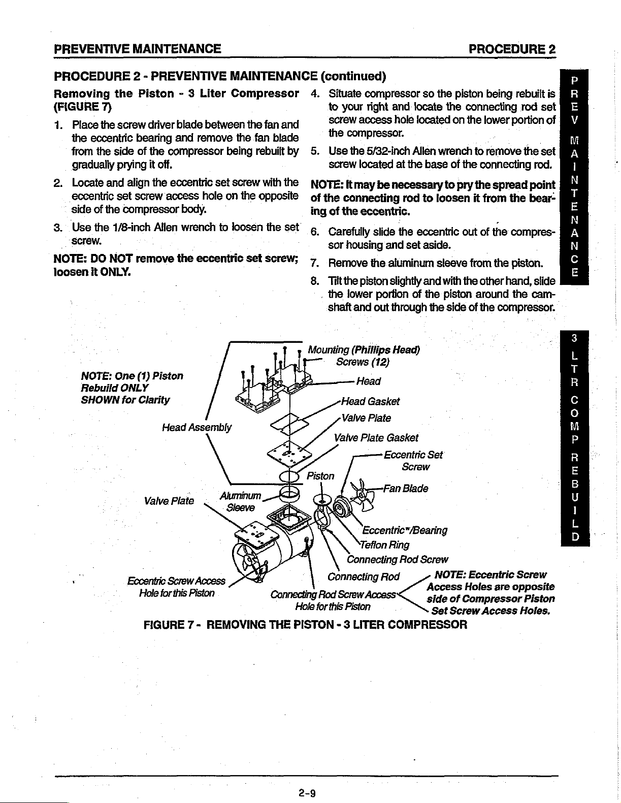
PREVENTIVE
MAINTENANCE
PROCEDURE
2
PROCEDURE
Removing
(FIGURE
1.
Place
the
eccentric
from
the
gradually
2.
Locate
eccentric
side
of
3.
Use
he
NOTE:
loosen
DO
it
NOTE:
Rebuild
SHOWN
2 - PREVENTIVE
the
Piston - 3
7) to
the
screw
side
prying
and
set
the
1/8-inch
NOT
driver
blade
bearing
of
align
screw
compressor
remove
and
the
compressor
it
off.
the
eccentric
access
body.
Allen
wrench
the
remove
eccentric
MAINTENANCE
Liter
Compressor
between
the
being
set
screw
hole
on
the
to
loosen
the
fan
and
fan
blade
rebuilt
with
the
by
opposite | of
the
set’
set
screw;
(continued)
4.
Situate
screw
the
5.
Use
screw
NOTE:
the
ing
of
к.
Carefully
sor
7,
Remove
ONLY.
8.
Tilt
.
the
shaft
Mounting
One
ONLY
for
Piston
(1)
Clarity
Head
Assembly
FOR
Re
と
bå
compressor
your
right
and
access
hole
compressor.
the
5/32-inch
located
Itmay
at
be
necessary
connecting
the
eccentric.
slide
the
housing
the
lower
and
(Phillips
Screws
Head
Valve
Valve
and
the
aluminum
piston
slightly
portion
out
through
(12)
Gasket
Plate
Plate
Gasket
Head)
so
the
locate
located
Allen
wrench
the
base
rod
to
loosen
eccentric
set
aside.
sleeve
and
of
the
the
piston
the
connecting
on
the
of
the
to
pry
the
out
from
with
the
piston
side
of
being
rebuilt
lower
portion
to
remove
connecting
spread
it
from
the
of
the
compres-
the
piston.
other
hand,
around
the
the
compressor.
rod
set
of
the
set
rod.
point
bear-
slide
cam-
is
3
L
T
R
C
ο
M
P
a)
e
vs
E
ke
때
Eccentric
Fan
Plate
Valve
Eccentric“/Bearing
Tefion
Ring
|
Hole
Screw
this
tor
Eccentric
Access
Piston
ň
Connecting
Hole
for
FIGURE 7 -
REMOVING
THE
PISTON - 3
Connecting
Connecting
Rod
Screw
Access
this
Piston
LITER
Rod
COMPRESSOR
Set
Screw
Blade
. .
Rod Screw
NOTE:
Access
side
Set
Eccentric
are
Holes
of
Compressor
Screw
Access
Screw
opposite
Piston
Holes.
R
E
B
1
上
D
2-9

PROCEDURE
2
|
PREVENTIVE
MAINTENANCE
PROCEDURE
Installing
DO
NOT
lubricate
The
compressor
bearing.
.
aşa
ei
new
connecting
2.
Install
the
μ.μ...
ue
3.
L
т
R
с
o
M
P
R
E
B
U
1
through
3.
Continue
sor
housing
the
ecceniric
The
eccentric
the
eccentric
[damage
м
Reinstall
on
the
ing
to
rod.
L
D
Nib
(Camshaft)
Connecting
Rod
2 - PREVENTIVE
the
New
Piston
or
eccentric
bead
of
Hemon # 846
rade
rod.
new
piston
the
side
of
moving
nib
the
the
eccentric
piston
with
the
nib
(camshafi).
set
screw
(shaft).
compressor.
eccentric
(FIGURE
WARNING
use
oil
on
any
uses
κος
o
ne
by
inserting
the
compressor
up
into
the
connecting
CAUTION
MUST
Failure
ensuring
sits
inside
Piston
Access
(Atter
Centered
reinstalled
install
face
to
・
the
Set
Screw
Hole
Piston
Aluminum
rod
do
Piston).
MAINTENANCE
8)
moving
ul Lag
the
body.
upper
situated
」
the
so
that
piston
parts.
οκ.
fi
at.
piston
head
compres-
around
flat
spot
on
may
cause
the
bearing
connect-
Piston
Connecting
Rod
(Slide
Over
Nib).
is
and
Eccentric
into
Compressor,
Sleeve
upright,
Compressor
Cut-away
is
onto
(continued)
5.
Align
the
front
the
front
face
of
.032
(1/16-inch).
6.
Apply a small
of
connecting
7.
Install
connecting
b
DO
NOT
[HS
NOT
force
aluminum
Teflon
piston
8.
9.
10.Hold
for
ring
i
unusable
Tum
position.
Place
ton
head
sleeve
rests
ing
and
-
Piston
*/Teflon
Y)
Housing
Clarity
may
bie.
the
eccentric
the
aluminum
at a 45°
the
piston
onto
on
the
over
Head
Ring
the
locator
the
face
of
the
of
the
bearing
amount
rod
screw.
rod
of
Hernon
screw
connecting
leaving a clearance
11423
and
torque
rod
with
to
threads
to
15
in.
OVERTIGHTEN,
CAUTION
become
until
sleeve
o
angle
in
place
piston
ribs
piston.
С)
sleeve
damaged
with
of
onto
piston
.
is
partially
the
and
gently
head
and
the
compressor
”
Eccentric
E
Connector
piston.
and
make
in
the
over
tooled
edge
rotate
down
Aluminum
Sleeve
Eccentric
Screw
Eccentric
Bearing
Screw
Ecceniric
The
the
full
the
pis-
up.
the
until
hous-
.
Set
Rod
up
it
Bearing
Bo
CONNECTING
Spread
ROD
‘Connecting
Rod
Screw
DETAIL
FIGURE 8 -
INSTALLING
NEW
Nib
ECCENTRIC
PISTON
|
E
DETAIL

PREVENTIVE
MAINTENANCE
PROCEDURE
2
PROCEDURE
Alignment
1.
Hold
sleeve
eccentric
2.
As
the
rod
will
tion.
3.
If
connecting
aligned
4.
If
this
STEPS
5.
If
connecting
tact
Invacare
6.
‘Twist
the
ton
until
teflon
ring
7.
With
the
cator
ribs,
side
of
and
position
plate
line
compressor
bly.
8.
Securely
the
flat
Ensure
the
may
injury.
9.
10.
11.
that
flat
spot
result
Reinstall
front
of
Temporarily
just
replaced
piston.
Begin
at
ton
on
2 - PREVENTIVE
of
the
Piston
down
with
with
the
other.
piston
travels
rock
from
front
rod
rocks
on
the
eccentric
is
evident,
3-8
for
loosen
INSTALLING
rod
cannot
Technical
aluminum
sleeve
aluminum
the
tighten
spot
in
the
FIGURE 2 for
the
is
approximately
of
the
piston.
set
the
individual
compressor
it
until
up
with
the
housing.
the
on
the
CAUTION
eccentric
on
the
cam
damage
the
fan
blade
eccentric
reinstall
to
simplify
opposite
(FIGURE
one
hand
up
and
down,
to
back
side
to
bearing.
set
THE
be
properly
Service.
sleeve
sieeve
the
six
This
connecting
nib
set
to
the
side
back
firmly
valve
onto
the
six
(6)
(6)
holes
aligns
(camshaft)
screw
shaft.
compressor
securely
(FIGURE
valve
installation
installation
of
the
MAINTENANCE
8)
and
slowly
the
connecting
in
normal
]
side,
the
rod
screw
and
PISTON.
aligned,
up
onto
the
centered
seated
plate
aluminum
holes
in
the
rod
onto
from
in
the
the
top
piston
screw
(FIGURE
is
aligned
Failure
3).
plate
compressor.
or
over
for
of
of
the
to
possible
the
the
the
new
tum
opera-
is
mis-
repeat
con-
pis-
on
the
lo-
that
sleeve
valve
of
the
assem-
against
3).
with
do
so
nib
in
piston
other
pis-
(continued)
Because
that
you
1.
Replace
side
2.
Use
remove
keeper,
3.
Remove
of
4.
Remove
and
5.
Remove
6.
ReverseSTEPS
gasket
7.
Remove
install
the
valve
NOTE:
bly
at
8.
After
placed,
sleeves
into
NOTE:
of
position
head
lowsystem
9.
Reinstall
noting
bly
10.
Tighten
torque
11.
Reinstall
of
the
word
when
of
the
the
the
valve
valve
onto
the
valve
plate.
DO
this
time.
the
the
Ensure
when
assembly.
the
and
to
CAUTION
tooling
installing
the top
valve
small
the
and
the
the
from
the
the
new
plate
NOT
other
install
ensuring
cut-out
pressures.
the
markings
valve
the
45
the
of
"UP"
on
the
and
plate
common
valve
screws
valve
restraint
valve
keeper,
plate.
bottom
the
old
gasket
1-5
the
valve
old
gasket
gasket
gasket
attempt
piston
the
valve
that
in
the
that the
reinstalling
Doing
head
assembly
plates
screws
in.
Ibs.
compressor.
the
valve
keepers,
the
valve
keeper
valve
keepers.
bottom
valve
bottom
to
plate.
in
to
top
gaskets
this
made
were
in a criss-cross
valves
at a time.
(flathead)
securing
to
the
and
valve
screw,
from
install
in
the
into
reinstall
and
plates
the
the
valve
of
the
the
the
the
head
compressor
the
underside
the
valves
over
valve
of
the
piston.
are
not
valve
will
prevent
onto
when
the
removed.
screwdriver
the
valve
valve
valve
NEW
assembly
have
the
keeper
pinched
plates
the
ensure
is
facing
by
doing
valve,
plate.
from
keeper
plate.
plate.
valves
head
head
assem-
been
aluminum
strip
and
leaks
:
valve
head
assem-
manner
one
to
valve
the top
strip
and
and
and
of
the
re-
fits
or
out
the
and
plates
and
re
ee
A
XA
3
上
T
R
C
o
M
P
R
E
B
U
|
L
D
Replacing
Gaskets
NOTE:
they
were
completely
plate.
this
and
eguately
(FIGURE
Ensure
are
facing
in
when
Ensure
may
inhibit
severely
compress
the
Top and
9)
that
in
the
removed
cover
the
that
no
their ability
reduce
Bottom
when
installing
same
direction
from
each
compression
dirt
or
grease
to
open
the
compressors
air.
Valves
plate
opening
and
the
new
that
the
and
contacts
and
close
ability
valves,
old
ones
that
in
the
valve
them
properly
to
they
as
ad-
2-11
12.
Run
unit
hoses
and
13.
If
crossover
approximately
themselves,
vacare
page
Technical
of
and
check
crossover
tube(s)
1/4-tum.
leaks
this
instruction
for
leaks
tubes.
leak,
gently
should
Service
sheet.
around
Once
stop.
at
the
compressor
rotate
the
"O"
ring(s)
If
not,
contact
number
tube(s)
seat
In-
on
back

PROCEDURE
2
PREVENTIVE
MAINTENANCE
PROCEDURE
14.
Take
SURE
Re)
VICE
oe
—.
MOQOZP2mMAZ—Psz
3
L
T
2 - PREVENTIVE
pressure readings
TAP-IN
MANUAL).
(Phillips
Screws
KIT
Mounting
Head)
(6
Head)
to
INSTALLATION
per
Head
Valve
Keeper
/
IN
FIGURE 9 -
Gasket
Valve
Restraint
INSTALLING
ensure
TOP
MAINTENANCE
proper
system
AND
BED
PRESSURE
Head
Compression
Opening
Flapper
SIDE
THE
TOP
(continued)
pressures
.
under
AND
BOTTOM
(Refer
CHECK
to
PROCEDURE
in
the IRC3LX/
Valve
Valve
FLAPPERS
Plate
Plate
AND
21 - SIEVE
IRCSLXARCSLXO2SER-
Gasket
BOTTOM
BED
Compression
Opening
SIDE
GASKETS
PRES-
under
R
с
ο
Μ
Ρ
R
E
B
U
1
L
D

PREVENTIVE
MAINTENANCE
PROCEDURE
2
PROCEDURE
TO
PREVENT
DISCONNECT
ELECTRICAL
Compressor
*NOTE:
mas
pressors
located
number
This
Model
use
on
does
the
work.
The
5-Liter
Rebuild
ON
ONDA
.
Kit
Two
(2)
Two
(2)
Four
(4)
Four
(4)
Two
(2)
Two
(2)
Eight
(8)
Four
(4)
Four(4)
2 - PREVENTIVE
CAUTION
ELECTRICAL
CONCENTRATOR
OUTLET
Top End
kit
is
designed
2639
CE
44
or
this
rebuild
front
of
the
not
begin
in
Thomas
contains
Tefion Piston
Aluminum
Valves
Valve
Head
Valve
Head
Valve
Connector
2639
the
Piston
Restraints
Gaskets
Plate
Gaskets
Mounting
Screws
(Crossover)
MAINTENANCE
SHOCK,
BEFORE
SERVICING.
Rebuild - 5
for
rebuilding
2619
CE
44.
kit.
The
serial
compressor.
this
way,
this
or
2619
following:
Rings
Sleeves
Screws
Tube
ALWAYS
FROM
Liter
the
Tho-
These
Compressor
number
If
the
kit
will
"O"
Rings
com-
serial
not
is
(continued)
6.
Remove
sembly.
NOTE:
7.
8.
9.
10.
Replace
Use a small
edge
of
over
tubes
tubes.
Slide
NEW
of
the
crossover
Gently
of
reinstall
one
(1)
Reinstall
crossover
Head
Mounting
(TORX)
Screws
(8)
the
crossover
all
four
flat
screwdriver
the
"O"
rings
and
remove
"O"
rings
tubes.
the
compressor
the
remaining
tubes.
tubes
(4)
“O"
rings.
to
and
grooves
“O" rings
into
the
grooves
crossover
head.
head
onto
from
get
from
tubes
the
the
head
between
in
the
cross-
crossover
at
each
into
the
ends
of
Markthe
as-
the
end
end
the
Head
«mov
A
> E
LOUER
vara
Tools
One
One
Reguired:
(1)
Phillips
(1)
Phillips
Torque
One
(1)
1/8-inch
Torque
One
(1)
5/32-inch
Torque
One
(1)
Common
ment
Removing
and
Replacing
(FIGURE
1.
Unplug
2.
Carefully
tor.
(Refer
COMPRESSOR
3.
Use
the
eight
(8)
and
valve
4.
Mark
the
reinstallation
5.
Grasp
apart.
Head
TORX
#2
Screwdriver
Wrench
Allen
Wrench
Allen
Wrench
(for
(Flathead)
(for
Valve
and
Marking
Crossover
10)
concentrator.
remove
to
compressor
PROCEDURE
ASSEMBLY
TORX
both
T-25
screws
plates
heads
and
head
that
to
the
and
set
assemblies
T-25
(for
Retainer
Wrench
(for
Eccentric
Wrench
Rod
Clamping
Screwdriver
Screw).
the
Compressor
Tube
torque
wrench
secure
the
compressor.
valve
plates
valve
plates
and
Driver.
Attachment
Screws).
attachment
Set
Screw).
attachment
Screw).
attach-
Heads
"O"
Rings
from
concentra-
7 - REPLACING
OR
CAPACITOR).
to
remove
head
assembly
to
ensure
aside.
gently
proper
pull
for
for
for
the
them
“o”
Ring
N)
FIGURE
10 - REMOVING
COMPRESSOR
CROSSOVER
NOTE:
stall
piston
the
After
Flapper
being
other
piston
componenis.
DO
NOT
lubricate
The
compressor
sealed
bearing.
E
CROSSOVER
HEADS
removing
Plate
onto
rebuilt.
This
and
WARNING
or
use
eccentric
TUBE
AND
AND
TUBE
the
head
the
"O"
side
restricts
possible
oil
on
any
uses a precision
i
(Ring
MARKING
REPLACING
RINGS
assembly,
opposite
movement
damage
moving
o
“©
THE
rein-
the
of
to
the
parts.
TS&060
or-cuoma
2-13
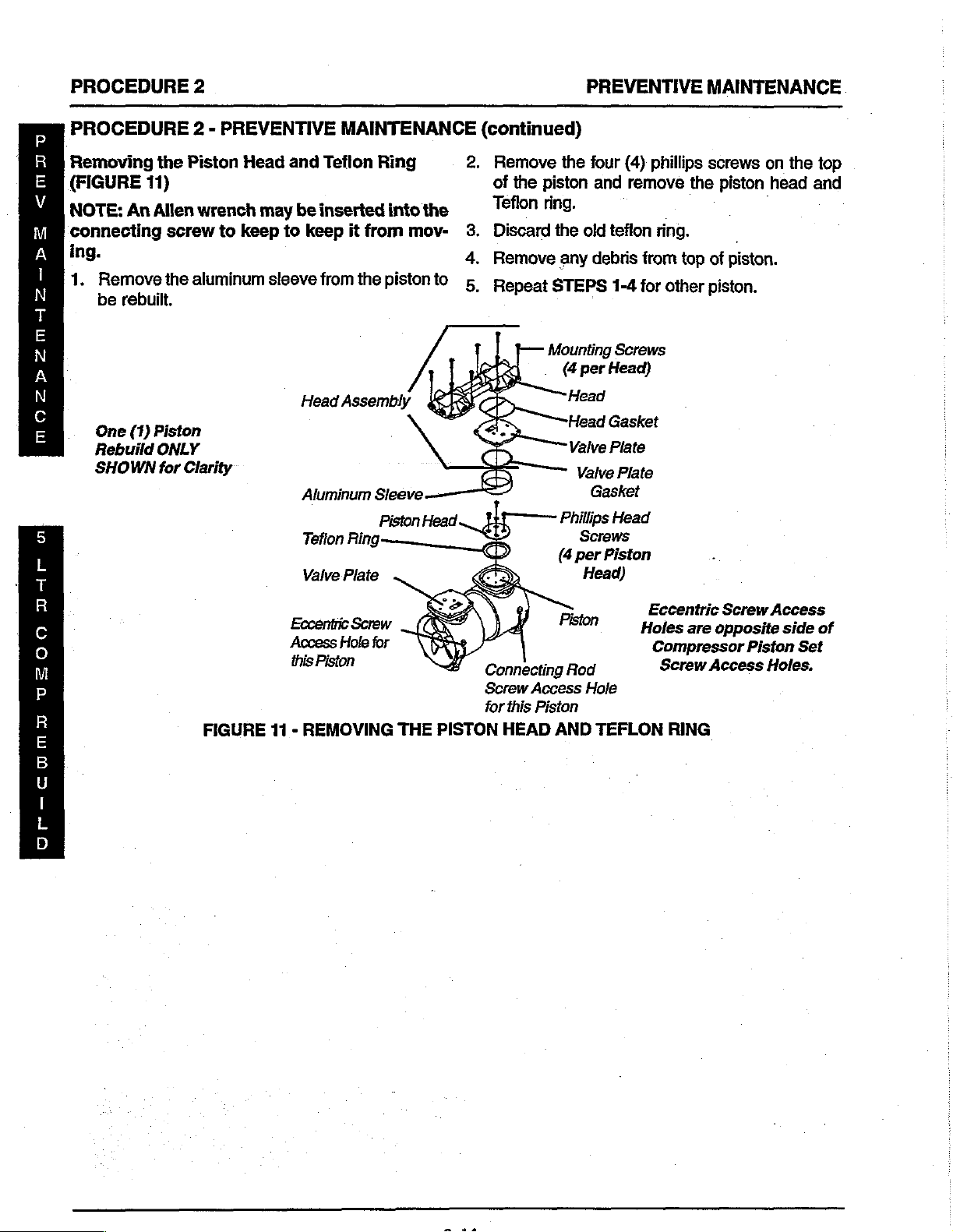
PROCEDURE
PROCEDURE
2
2 - PREVENTIVE
MAINTENANCE
(continued)
PREVENTIVE
MAINTENANCE
Removing
(FIGURE
ee
NOTE:
connecting
ing.
1.
Remove
be
μα
5
上
T
R
C
ο
M
P
R
E
B
U
I
L
D
One
Rebuild
SHOWN
the
11)
An
Allen
screw
the
rebuilt.
(1)
Piston
ONLY
for
Clarity
Piston
wrench
aluminum
FIGURE
to
Head
and
may
be
keep
to
sleeve
Eccentric
Access
this
11 - REMOVING
Teflon
inserted
keep
it
from
the
Aluminum
Tefion
Ring:
Valve
Plate
,
Screw
Hole
Piston
Ring
into
the
from
mov-
pistonto
Sleeve
for
THE
PISTON
2.
Remove
of
the
piston
Teflon
Discard
3.
4
.
Remove
5
Repeat
Connecting
Screw
Access
for
this
Piston
HEAD
the
four
and
ring.
the
old
any
debris
STEPS
Mounting
(4
per
Head
Head
Valve
Valve
Gasket
Phillips
Screws
(4
per
Head)
Pisto
n
Rod
Hole
AND
TEFLON
(4)
remove
teffon
from
1-4
for
Screws
Head)
Gasket
Plate
Plate
Head
Piston
Holes
phillips
ring.
Eccentric
Compressor
Screw
the
top
other
are
RING
screws
piston
of
piston.
piston.
Screw
opposite
Access
on
the
head
Access
side
Piston
Set
Holes.
top
and
of

PREVENTIVE
MAINTENANCE
PROCEDURE
2
PROCEDURE
Installing
Heads
Piston
stalling.
ton
1.
2.
3.
(FIGURE
head
This
head
Place
position
Rest
the
and
center
Install
into
the
2 - PREVENTIVE
the
New
MUST
ensures
and
will
the
aluminum
on
the
new
Teflon
the
the
piston
aluminum
Teflon
12)
CAUTION
prolong
compressor
ring
head
Rings
be
rotated
proper
sleeve
ring
with the
over
sleeve.
Aluminum
Уаме
wear
it's
life.
onto
housing.
on
the
piston
the
Piston
Рав
MAINTENANCE
and
Piston
90°
when
on
rein-
the
pis-
(continued)
4.
Install
snug
sleeve.
5.
Once
piston
screws
its
mounting
aluminum
head.
piston
.
ring
Heat
sleeve
and
©.
DO
NOT
Teflon
render
—
Sleeve — ©
and
tighten
to
align the
the
Teflon
head
to
30
force
aluminum
ring
the
piston
Phillips
Piston
Screws
«
per
Teflon
Head
Head)
Ring
ring
and
in.
Ibs.
CAUTION
may
unusable.
the
phillips
Teflon
aluminum
ring
is
centered
sleeve
become
head
with
the
properly
sleeve,
onto
damaged
One
Rebuild
SHOWN
screws
aluminum
with
torque
piston.
(1)
Piston
ONLY
for
Clarity
until
the
the
The
and
Ke
li
e
A
€
5
L
T
R
C
e)
M
P
FIGURE
installing
13)
NOTE:
same
ing
and
sion
no
dirt
plates
and
compressor's
air.
Replace
one
Because
that
ing
Top
Ensure
direction
that
opening
or
grease
as
this
close
side
of
of
the
word
you
when
and
they
in
properly
ability
the
the
tooling
12 - INSTALLING
Bottom
that
new
that
the
completely
the
valve
contacts
may
inhibit
and
to
adequately
top
and
valve
"UP"
installing
plate
CAUTION
of
the
on the
Flappers
valves
old
ones
cover
plate.
the
their
severely
bottom
at a time.
valve
valve
the
valve
THE
(FIGURE
are
facing
when
the
compres-
Make
valves
ability
reduce
compress
valves
keepers,
keeper
keepers.
NEW
in
the
install-
sure
that
or
valve
to
open
the
by
doing
ensure
is
fac-
TEFLON
the
1.
Use
to
restraint,
the
2.
Remove
from
3.
Reverse
bottom
4.
Torque
5.
Install
and
the
6.
After
valve
stall
ing
and
RINGS
the
smail
remove
valve
the
the
bottom
STEPS
valves
valve
the
the
valve
valve
the
other
plates
ihe
head
the
markings
valve
AND
common
the
valve
valve
keeper,
plate.
valve
onto
screws
head
plate
plate.
piston
over
assembly
plates
PISTON
screw
screw,
side
of
1-2
to
the
to
gasket
gasket
has
the
aluminum
onto
made
when
were
removed.
HEADS
(flathead)
securing
and
valve
valve
keeper,
the
vaive
install
valve
in
the
plate.
12
in.
lbs.
the
compressor
into
been
the
the
the
rebuilt,
sleeves
valve
head
screwdriver
the
valve
to
the
top
and
valve
plate.
NEW
top
and
head
underside
install
and
rein-
plates
not-
assembly
R
Ε
B
U
|
L
of
D
of
the
2-15

PROCEDURE
2
PREVENTIVE
MAINTENANCE
5
L
т
R
C
o
M
P
«MO
E
A
E
πο
πι
NOTE:
out
and
leaks
7.
8.
9.
Ensure
of
position
the
and
Tighten
manner
Use a torque
and
torque
criss-cross
Reinstall
that
when
head
assembly.
low
system
the
screws
snug.
until
each
manner.
the
compressor
7 - REPLACING
OR
CAPACITOR).
Head
.
Gaskel
Head
Plate
Valve
Plate
Valve
Gasket
the
gaskets
reinstalling
Doing
are not
the
valve
this
will
pinched
prevent
pressures.
on
the
heads
NOT
DO
wrench
. N
with
the
head
screw
(Refer
COMPRESSOR
—
D
in a criss-cross
tighten
completely.
TORX
to
to
T-25
40
in.
ibs.
PROCEDURE
ASSEMBLY
.
00000
Ρ
D
Screw
Valve
Compression
Opening
under
Valve
or
plates
drive
ina
ews
Valve
:
X
10.
Run
unit
sor
hoses
TEST).
11.
If
crossover
approximately
themselves,
Invacare.
back
page
12.
Take
pressure
BED
PRESSURE
AND
BED
IRC5LX/
Valve
Gasket
Head
\
Valve
Restraint
Valve
Head
7
and
check
(Refer
tube(s)
for
to
PROCEDURE
leak,
1/4-turn.
should
leaks
Technical
of
this
Service
instruction
|
readings
TABA
PRESSURE
IRC5LX02
Plate
Gasket
SERVICE
CD
GS
ES
Q
3
~
leaks
around
gently
rotate
Once
stop.
at
sheet.
to
ensure
KIT
INSTALLATION
CHECK
in
"O"
19 - LEAK
the
ring(s)
not,
If
the
number
proper
the
compres-
tube(s)
seat
contact
on
system
IRC3LX/
MANUAL).
Vaive
Plate
Compression
Opening
under
Screw
Valve
R
E
B
υ
I
L
D
TOP
SIDE
BOTTOM
SIDE

|
ge”
Thomas
2619
rebuild
kit
The
Thomas
most
Estimates
are
definitely
compressor
service.
proper
Having
but
many
all
however,
:
yourself
tight!
procedure
STEP
:
fans.
‘STEP
STEP
from 1 (ONE)
as a template.
STEP
acetone . After
flappers
(standard
they
very
recirculate
STEP
should
gaskets
them
widely
are
still
being
maintenance
the
half
the
service
of
them
if
and
We
of
1:
"Then
2:
3:
4:
and flapper
screwdriver
Note:
You
are
not
tight.
5:
replace
and
out.
be
With
will
Mark
Remove
Valve
Now
Upon
double
used
that
over
used
considered
has
been,
today's
of
components
battle,
be
you
after
the
remove
must
replaced
In
air
sleeve
Suggested
the
centers
doing
it
have
reading
discuss
Thomas
the
compressors
the
all
plate
plate,
you
clean
cleaning
restraints.
replace
this
case
and
lose
completion
all
gaskets
o-rings
WOB-L®
compressor
500,000
in
this
as
and
always
cost-conscious
this
vital
to
rebuild
rest
is
begging
properly?
what
this
the
proper
2619
“head”
gaskets,
rebuild:
will
the
plate
install
and
7/16
the
your valve
your
volume/pressure.
of
and
you
tool
(Awl
compressor
in
Thomas
industry.
the
lion's
will
component
the
know-how!
for
your
Its
it
takes
article
installation
series
compressor.
intake,
screws.
seals
and
Remove
need
the
with
hot
the
new
Required
or
3/8
flapper
seal
may
compressor
the
valve
seals.
may
or
With
need
small
is
the
the
industry.
compressors
That
would
share.
be
an.
companies,
is a must.
compressor
business,
tough
you
you
exhaust
o-rings.
flappers
other
soapy
valve
tools
wrench)
restraints,
not
will
plates
the
to
screwdriver)
item
With
to
say...
can
do
can
do
and
for
use
water,
if
be
you
head
scrape
The
can
test
and
STEP
replaced
prefer
so
we
METHOD
remove
of
not
careful
screw
is
torch
so
should
Note:
it
bearings!
necessary.
it
Mi
remove
bring
your
on
each
cup
plate
notch
be
indentations
the
piston
to
the
necessary.
sealant
will
watch
going
CAUTION:
their
opposing
working
6:
Now
that
we
are
ready
rebuilding
will
discuss
1:
With
the 4 piston
be
found
remove
to
the
Loc-tite
seal
with
in
not
to
expand
do
the
BE
CAREFUL
If
Step
the
piston
piston
of
the
in
the
the
the
at
the
strip
the
the
trick.
this
1:
After
to
brand
four
cylinder
screw
center
of
top
plate.
original
and
ensure a good
the
off
stroke,
configuration,
Now
tighten
cup
material,
center.
When
you
side.
This
on
the
first
all
gaskets
to
with
the
both
methods.
the
top
screws.
local
them.
cylinder
metal
not
occurs
insert
can
major
all
cup
seal.
the
top
thread
piston
sleeve
holes.
of
the
the
flapper
If
you
the
in
an
fit.
As
guide
©
bringing
damage
of
course
piston.
and
seals
rebuild
cylinder
cylinder
hardware
In
surrounding
screws
the
sleeves
sleeve
These
store
the
event
sleeves
to
of
sealant and
top
You
and use a propane
burn
the.
repair
have
To
install
its
stroke.
screws.
and
match
will
top plate.
on
the
like
you
however,
screws
“X”
you
with
configuration.
tighten
it
down
pistons
the
cup
is
not a problem
have
been
pistons.
of a difficult
the
stator
will
been
the
put
Place
notice a small
There
intake
can
it
the
the top
to
to
material
Some
installed,
installed,
screws
so
Now
will
be
very
screw,
or
be
removed
new
seal
get
one
drop
the
the
top
will
also
side
match
is
keep
the
these:
not
thread
This
plate
it
top
on
that
new
of
from
of.
the
when
Page 5 Service
Tech
Today,
September
1993

--Step 6 cont.
METHOD
loosen
side
of
eccentric
Required
When
same
Required
screwdriver
After
eccentric
tric
is
ZEP-45
scréwdriver
eccentric)
2:
the
eccentric
the
compressor
set-screw.
tool
the
eccentric
with
the
tools
to
the
piston
off
too
tight
lubricant
(inserted
to
CAUTION:
will
cause
heat
After
removal
bearing
and
see
place
piston
On
thread
aligning
the 4 screws
for
listen
for
STEP
the
top
9.
piston
screws.
all 4 of
sealant.
the
damage
the
Remove
1/8
allen
is
piston.
5/32
allen
separate
is
loose
of
the
shaft.
to
pull
or
remove
DO
NOT
damage
of
the
or
rattles,
in a vice
DIFFICULTIES?---see
piston
Now
top
plate
in
an
“X"
the
cylinder
set-screw.
housing
There
to
"T"-handle.
loose,
you
"T"-handle
the 2 halves
you
can
In
many
it
off,
if
so,
equivalent,
in
the
the
eccentric.
use
to
piston,
then
hole
heat
the
eccentric
inspect
looseness,
if
the
bearing
and
remove
top
screws
install
the
to
the
pattern.
new
connecting
sleeves.
is a
hole
access
will
the
need
to
and a standard
of
the
piston.
pull
the
piston
cases
the
you
should
use
a
for
loosening
or
flame
as
bearing!
the
eccentric
shake
the
needs
replaced
all
of
Method
put a drop
cup
seal
rod.
Now
in
the
do
the
and
eccen-
use
the
this
bearing
the
of
by
Tighten
After
the
compressor.
Note:
can
tighten
Re-install
your
standard
on
the
eccentric
Required
After
tightening
back
it
off
„the
eccentric-to
STEP
7:
re-assemble
you
put on
configuration)
1
piston
Watch
it
through
the
eccentric,
screwdriver.
tool
5/32
until
After
the
the
has
been
assembled,
the
piston
bearing
the
you
screw
the
hole
spread
with
15
inch
piston
to
in
the
Next
15
in
pound
tighten
hear a “pop”.
tighten
"spin-balance".
completing
compressor.
heads/housings
Step 6 tó
(Watch
to
insert
make
sure
the
housing.
piston
torque
the
apart
the
lbs
of
torque.
"T"-handle
eccentric,
This
will
both
the
marks
determine
it
in
the
you
with
piston
then
allow
pistons,
-
that
the
Pago 6 Service
Tech
Today,
September
1993
STEP
Method 2 of
balance
COMPRESSOR
will
out
compressor
and
the
compressor,
normal.
shaft.
2-18
8:
This
Step
the
compressor.
need
to
make a test
of
the
concentrator.
connected
the
other
leads
compressor.
you
The
sound
This
action
step
is
only
6)
Now
we
DO
IN
THE
CONCENTRATOR!
lead
---With
to a test
connected
Cover
will
the
intake
notice a clicking
is
the
eccentrics
will
help
balance
needed
are
NOT
to
start
the
lead
to
the
side
when
ready
to
INSTALL
the
compressor
assembled
(AC
power
capacitor,
of
the
noise,
slapping
the
eccentric
using
spin-
THE
You
side)
start
this
on
the
is
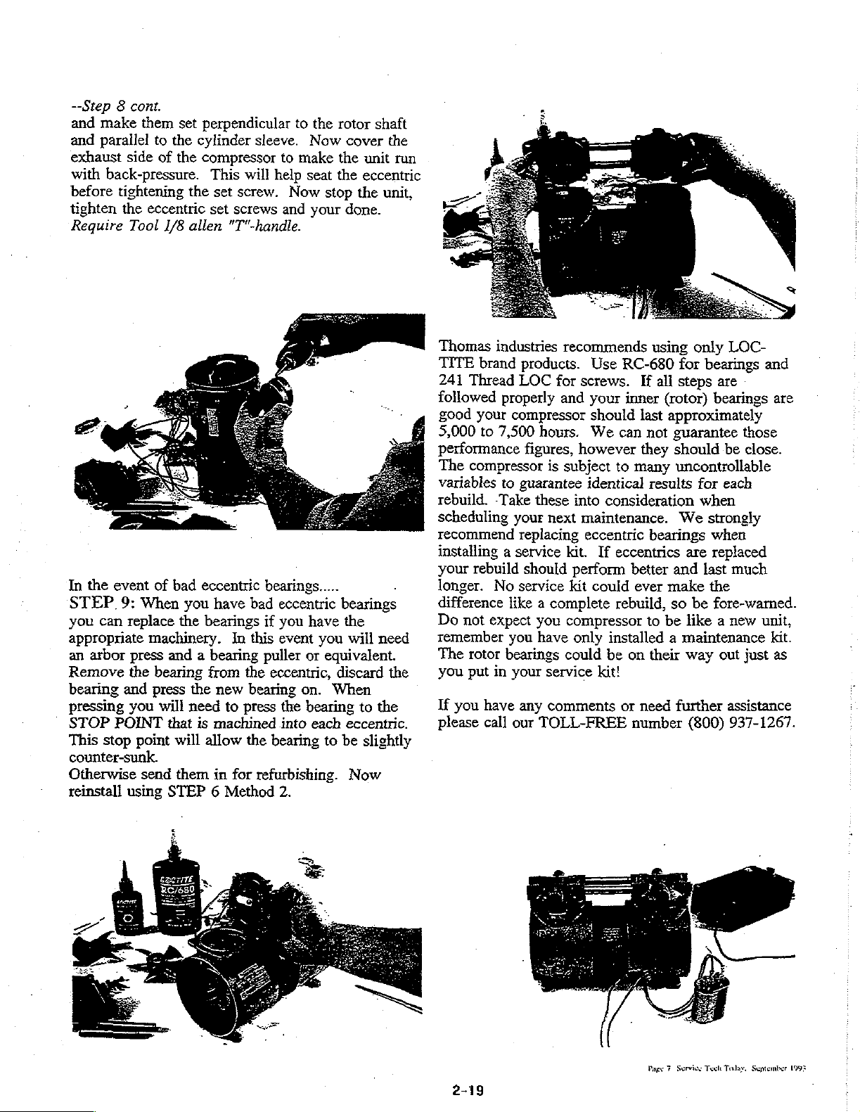
--Step 8 cont.
and
make
them
and
parallel
exhaust
with
back-pressure.
before
tighten
Require
to
side
tightening
the
eccentric
Tool
the
of
1/8
set
perpendicular
cylinder
the
compressor
This
will
the
set
screw.
set
screws
allen
"T"-handle.
to
sleeve.
to
make
help
Now
and
the
Now
seat
stop
your
rotor
shaft
cover
the
unit
the
eccentric
the
done.
the
run
unit,
In
the
event
of
STEP
you
appropriate
an
Remove
bearing
9:
can
replace
arbor
the
and
When
machinery.
press
bearing
press
pressing you
STOP POINT
This
stop
point
counter-sunk.
Otherwise
reinstall
send
using
bad
eccentric
you
have
the
bearings
In
“this
and a bearing
from
the
the
new
will
need
to
press
that
is
machined
will
allow
the
them
in
for
STEP 6 Method
bearings.....
bad
eccentric
if
you
event
puller
eccentric,
bearing
the
into
bearing
bearings
have
you
or
equivalent.
discard
on.
When
bearing
each
to
refurbishing.
2.
the
will
need
the
to
the
eccentric.
be
slightly
Now
Thomas
TITE
241
followed
good
5,000
performance
The
variables
rebuild.
scheduling
recommend
industries
brand
products.
Thread
LOC
properly
your
compressor
to
7,500
hours.
figures,
compressor
to
guarantee
-Take
these
your
replacing
recommends
for
and
is
subject
next
installing a service
your
rebuild
longer.
difference
Do
not
remember
The
rotor
you
put
If
you
please
should
No
service
like a complete
expect
you
you
have
bearings
in
your
service
have
any
comments
call
our
TOLL-FREE
could
using
Use
RC-680
screws.
your
should
We
however
identical
into
If
all
inner
(rotor)
last
approximately
can
not
they
to
many
results
consideration
maintenance.
eccentric
kit.
If
perform
kit
could
compressor
only
be on
kit!
bearings
eccentrics
better
ever
make
rebuild,
installed a maintenance
to
so
be
their
or
need
number
only
LOC-
for
bearings
steps
are
bearings
guarantee
should
those
be
close.
and
are
uncontrollable
for
each
when
We
strongly
when
are
replaced
and
last
much
the
be
fore-warned.
like a new
way
out
further
(800)
unit,
kit.
just
as
assistance
937-1267.
Page 7 Service
Tech
Today,
September
1993

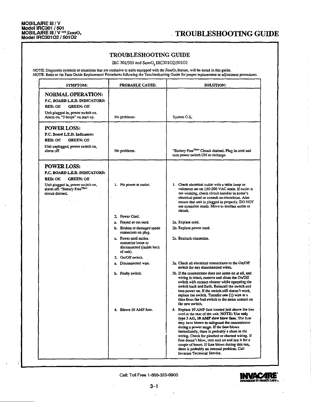
MOBILAIRE
Model
iRC301 / 501
MOBILAIRE
IRC30102
Model
It
/V
tl / V
““*SersO,
50102
/
TROUBLESHOOTING
・
GUIDE
NOTE:
Diagnostic
NOTE:
Refer
NORMAL
P.C.
RED:
Unit
Alarm
POWER
P.C.
RED:
Unit
alarm
POWER
P.C.
RED:
Unit
alarm
circuit
symbols
to
the
Parts
SYMPTOM:
OPERATION:
BOARD
L.E.D.
Off
GREEN:
plugged
in,
power
on,
“3
beeps”
LOSS:
Board
LED.
Off
GREEN:
unpiugged,
off.
BOARD
plugged
off.
LOSS:
Off
in,
“Battery
drained.
power
L.£.D.
GREEN:
power
or
situations
Guide
Replacement
INDICATORS:
Off
switch
on
start
up.
Indicators:
Off
switch
INDICATORS:
Off
switch
Free™”
that
on.
on,
on,
TROUBLESHOOTING
IRC
301/501
and
SensO,
IRC30102/50102
are
exclusive
to
units
Procedures
PROBABLE
No
problems.
No
problems.
1.
No
2
Power
а.
Frayed
“b,
Broken
‘connectors
e.
Power
connector
disconnected
of
3.
On/Off
a.
Disconnected
db.
Faulty
4.
Blown
equipped
following
power
at
Cord.
or
cut
or
damaged
cord
loose
unit}.
switch.
switch.
10
AMP
with
the
Troubleshooting
CAUSE:
outlet.
cord.
spade
on plug.
molex
or
(inside
back
wire.
fuse.
the
SensO,
GUIDE
feature,
Guide
for
System
О.К,
“Battery
turn
power
1.
«Check
voltmeter
not
working,
electrical
ensure
use
extension
circuit.
2a,
Replace
2b.
Replace
2c.
Reattach
3a.
Check
switch
3b.
If
the
wiring
switch
switch
tum
power
replace
time
the
new
4.
Replace
cord
type 3 AG,
may
during a power
immediately,
wiring,
fuse
doesn’t
couple
there
Invacare
wilt
be
noted
proper
replacement
SOLUTION:
Free™”
Circuit
switch
ON
electrical
all
for
concentrator
is
with
back
from
at
have
of
is
set
on
check
panel
or
that
unit
is
cords.
cord.
power
cord.
connector.
electrical
any
disconnected
intact,
remove
contact
and
forth.
on.
If
the
switch.
the
bad
switch.
10
AMP
the
rear
of
10
AMP
blown
surge.
there
Check
for
biow,
hours.
If
probably
Technicat
outlet
150-200
consult
plugged
the
switch
fuse
the
to
pinched
an
in
this
guide.
or
adjustment
drained.
to
Circuit
connections
does
cleaner
Transfer
safeguard
is
turn
fuse
internal
Service.
Plug
recharge.
with a table
VAC
scale.
breaker
an
ciectrician.
in
properly.
Move
to
another
to
wires.
not
come
and clean
while
Reinstall
still
one
to
the
located
NOTE:
blow
If
the
fuse
or
charred
unit
on
blows
problem.
the
(1)
same
just
the
and
during
switch
unit.
slow
probably a short
procedures.
in
cord
and
lamp
or
If
outlet
in
home’s
Also
DO
NOT
outlet
the
On/Off
on
at
all,
and
the
On/Off
operating
doesn’t
fuse.
concentrator
blows
switch
wire
contact
above
Use
The
in
wiring.
run
it
this
Call
the
and
work,
at
a
the
only
fuse
the
fora
run,
is
or
on
line
If
Cail:
Toll
Free
1-800-333-6900
3-1
innovation
in
Health
Care

TROUBLESHOOTING
GUIDE
MOBILAIRE
Model
Model
IRC30102 / 50102
MOBILAIRE
IRC301 / 501
Ill / V “*
Ht / V
SensO,
TROUBLESHOOTING
NOTE:
Refer
to
the
Parts
Guide
POWER
INTERNAL
SensO2
P.C.
RED:
Alarm
CONTROL
RED
GREEN © :
Fan
compressor
FLOW
P.C.
RED:
Rapid
Compressor
HIGH
P.C.
RED:
Unit
continuous
down.
high
innovation
in
Heath
Care»
SYMPTOM:
LOSS,
ONLY:
BOARD
LE-D.
Off
GREEN:
may
or
may
PANEL
@\:08
où
operates,
flowmeter
not
OBSTRUCTION:
BOARD
L.E.D.
Flashing
“beeping”
shut
PRESSURE:
BOARD
L.ED.
On
GREEN:
in,
plugged
alarm.
(Failure
pressure),
Replacement
Continued
POWER
INDICATORS:
Off
not
be
on.
INDICATORS:
YELLOW
light
operating.
INDICATORS:
GREEN:
alarm.
down
after 5 minutes.
INDICATORS:
Off
switch
power
Compressor
to
cycle
due
LOSS
RA:
on,
Off
-
on,
shut
to
Procedures
PROBABLE
5.
P.C.
a.
Damaged.
b.
Loose
following
Board.
or
damaged
the
GUIDE,
Troubleshooting
CAUSE:
connector.)
CONTINUED
Guide
for
proper
Sa.
Replace
ONLY - Unit
replacement.
manual.
5b.
Repair
or
replacement
SOLUTION:
board.
FOR
may
Refer
replace
connector.
or
adjustment
IRC501/501C/50102
need
retiming
timing
after
section
to
the
Or
1.
Transformer
a.
Faulty.
b.
Connector
disconnected.
с.
Faulty
2
P.C.
Faulty.
1.
Flowmeter.
a.
Setat
b.
Patient
obstructed.
Obstructed
humidifier
P.C.
1.
a.
Malfunction
wire.
Сай:
loose
wiring.
Board.
1/2
liter
tubing
bottle.
Board.
Той
Assembly.
or 1b.
or
less.
pinched
or
or
defective
or
disconnected
Ргее
1-800-333-6900
3-2
la.
Replace
Procedure 2 -
Reattach
1c.
Replace
Procedure 2 -
2.
Replace
ONLY - Unit
replacement.
manual.
ta.
Increase
prescribed
IRCPF-16
accurate
1b.
Replace
Jc,
Replace
.
1a.
Set
flow
connector
Check
voltage
connector
reads 0 volts
transformer
connector.
transformer
P.C.
flow
flow
Pediatric
flow
tubing.
humidifier
to 3 /min.
between
on a 200
assembly.
Removing
assembly.
Removing
Board,
FOR
may
need
Refer
to
the
above
1/2
is
1/2
liter
Flowmeter
Jevel.
bottle.
or S t/rnin.
P.C.
across
either
volt
when
unit
[Refer
Control
Panel
[Refer
Control
Panel
IRC501/50102
retiming
after
timing
section
liter
or
more.
or
less,
use
to
ensure
:
Locatě
Board
and
side
of
D.C.
scale.
shuts
down,
solenoid
molex
if
procedures.
board
in
this
:
to
(SensO2)].
to
(SensO2)}.
board
in
this
If
the
molex
valve.
voit
meter
replace
board.
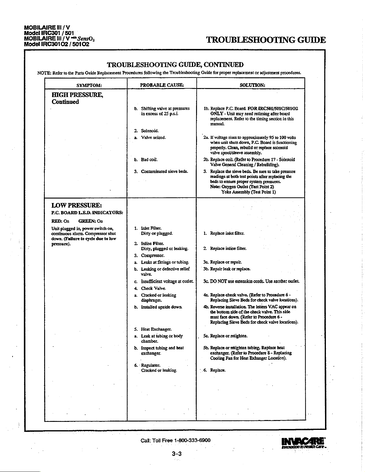
MOBILAIRE
Model
IRC301 / 501
MOBILAIRE
Model
IRC30102 / 50102
Ili
/V
ll / V*
SersO,
TROUBLESHOOTING
GUIDE
NOTE:
Refer
to
the
HIGH
PRESSURE,
Continued
ㆍ
LOW
PRESSURE:
P.C.
BOARD
RED:
On
Unit
plugged
continuous
down.
(Failure
pressure).
Parts
SYMPTOM:
LE.D.
GREEN:
in,
power
alarm.
to
Guide
Replacement
INDICATORS:
On
switch
Compressor
cycle
due
TROUBLESHOOTING
to
Procedures
on,
shut
low
following
PROBABLE
b.
Shifting
in
excess
2.
Solenoid.
a.
Vaive
b.
Bad
3.
Contaminated
1.
inlet
Dirty
2
Inline
Dirty,
3.
Compressor.
a.
Leaks
b.
Leaking
valve,
¢.
Insufficient
4.
Check
a.
Cracked
diaphragm.
b.
Installed
5.
Heat
a.
Leak
chamber.
b.
Inspect
exchanger.
6. - Regulator.
Cracked
GUIDE,
the
Troubleshooting
CAUSE:
valve
at
pressures
of
25
psi.
seized.
coil.
sieve
beds.
Filter.
or
plugged.
Filter.
plugged
or
leaking.
at
fittings
or
tubing.
or
defective
voltage
at
Valve.
or
leaking
upside
down.
Exchanger.
at
tubing
or
body
tubing
and
heat
or
leaking.
relief
outlet.
CONTINUED
Guide
for
proper
Ib.
Replace
ONLY - Unit
replacement.
manual.
.
2a.
If
voltage
when
unit
properly.
valve
spool/sleeve
2b.
Replace
Vaive
General
3.
Replace
readings
beds
to
Note:
Oxygen
Yoke
1.
Replace
2.
Replace
3a.
Replace
3b.
Repair
leak
3c,
DO
NOT
4a.
Replace
Replacing
4b.
Reverse
the
bottom
must
face
Replacing
5a.
Replace
5b.
Replace
exchanger.
Cooling
1.6.
Replace.
replacement
P.C.
Board.
may
Refer
rises
shuts
Clean,
coil.
(Refer
Cleaning / Rebuilding).
the
sieve beds.
at
both
ensure
proper
Outlet
Assembly
inlet
filter.
inline
filter.
or
repair.
or
replace.
use
extension
check
valve.
Sieve
installation.
side
of
down.
Sieve
or
retighten.
or
rétighten
(Refer
Fan
for
or
SOLUTION:
FOR
need
retiming
to
the
timing
to
approximately
down,
P.C.
rebuild
or
assembly.
to
Procedure
Be
test
points
system
(Test
(Test
cords.
(Refer
Beds
for
check
The
letters
the
check
(Refer
to
Beds
for
tubing.
to
Procedure 8 -
Heat
Exhanger
adjustment
IRC501/501C/50102
Board
replace
sure
after
Point
Point
to
valve.
Procedure 6 -
check
Replace
procedures.
after
board
section
95
to
100
is
functioning
solenoid
17 - Solenoid
to
take
pressure
replacing
pressures.
2)
1)
Use
another
Procedure 6 -
valve
locations).
VAC
appear
This
valve
locations).
heat
Replacing
Location).
in
this
volts
the
outlet.
on
side
Cait:
Toll
Free
1-800-333-6900
3-3
innovation
fi
Heakh
Care
=
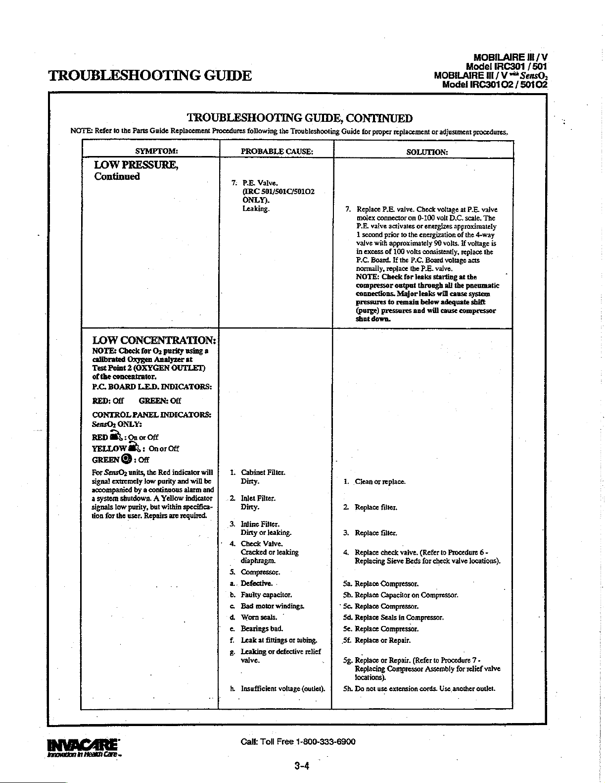
TROUBLESHOOTING
GUIDE
MOBILAIRE
Model
MOBILAIRE
Model
IRC301 / 501
Ill / V
IRC30102 / 50102
IN / V
"é
SensO,
NOTE:
Contin:
RED
For
Refer
to
the
Parts
SYMPTOM:
LOW
PRESSURE,
inued
LOW
CONCENTRATION:
NOTE:
Check
calibrated
Test
of
P.C.
RED:
CONTROL
SensOz
YELLOW
GREEN © :
signal
accompanied
a
system
signals
tion
Oxygen
Point 2 (OXYGEN
the
concentrator.
BOARD
Off
PANEL
ONLY:
a 3 On
EK, : On
SensO;
units,
extremely
shutdown. A Yellow
low
purity,
for
the
user.
Guide
Replacement
for
O2
purity
Analyzer
OUTLET)
L.E.D.
INDICATORS:
GREEN:
or
of
by a continuous
INDICATORS:
Off
or
the
Red
low
purity
but
within
Repairs
Off
Off
indicator
and
specifica-
are
required.
TROUBLESHOOTING
Procedures
using
2
at
will
will
be
alarm
and
indicator
following
PROBABLE
7.
PE.
(IRC
ONLY).
Leaking.
1.
Cabinet
Dirty.
2.
Inlet
Dirty.
3.
Inline
Dirty
4.
Check
Cracked
_
diaphragm.
S.
Compressor.
a..
Defective.
b.
Faulty
c.
Bad motor
d
Worn
e.
Bearings
f.
Leak
2.
Leaking
valve.
Insufficient
Valve.
Filter.
or
at
GUIDE,
the
Troubleshooting
CAUSE:
501/501C/50102
Filter.
Filter.
leaking.
Valve.
or
leaking
-
capacitor.
windings.
seals.
©
bad.
fittings
or
tubing.
or
defective
relief
voltage
(outlet).
CONTINUED
Guide
7.
1.
2.
3.
4.
Sa.
Sb.
*
Se.
Sd.
Se.
Sf.
-
5g.
Sh.
for
proper
replacement
Replace
P,E.
molex
P.E.
1
second
valve
in
excess
P.C.
normally,
NOTE:
compressor
connections.
pressures
(Purge)
shut
Clean
Replace
Replace
Replace
Replacing
Replace
Replace
Replace
Replace
Replace
Replace
.
Replace
Replacing
locations).
Do
not
valve.
connector
valve
activates
prior
with
approximately
of
100
Board.
If
replace
Check
output
Major
to
remain
pressures
down.
or
replace.
filter.
filter,
check
Sieve
Compressor.
Capacitor
Compressor.
Seals
Compressor.
or
Repair.
or
Repair.
Compressor
use
extension
or
SOLUTION:
Check
on
0-100
or
energizes
to
the
energization
volts
consistently,
the
P.C.
Board
the
P.E.
for
leaks
through
leaks
below
and
will
-
valve.
(Refer
Beds
for
on
Compressor.
in
Compressor.
(Refer
Assembly
cords.
adjustment
voltage
at
volt
D.C.
approximately
of
90
volts.
If
replace
voltage
valve,
starting
at
all
the
will
cause
adequate
cause
compressor
to
Procedure 6 -
check
valve
.
to
Procedure 7 -
for
Use
another
procedures,
P.E.
valve
scale.
The
the
4-way
voltage
is
the
acts
the
pneumatic
system
shift
locations).
relief
valve
outlet.
innovation
in
Heak
Care
>
Call:
Toll
Free
1-800-333-6900
3-4

MOBILAIRE
Ill
/V
MOBILAIRE
Model
NOTE:
H/V
W/V ™ SensO,
IRC30102
Refer
LOW
Continued
FLUCTUATING
50102
/
to
the
Parts
SYMPTOM:
CONCENTRATION,
:
Guide
ーー
TROUBLESHOOTING
Replacement
FLOW:
Procedures
6.
a.
b.
7.
8.
9.
a.
b.
10.
a,
b.
11.
12.
a.
b.
13.
a.
b.
14.
15.
:
"1
а.
GUIDE,
following
PROBABLE
-Heat
Leak
Inspect
exchanger.
Regulator.
Cracked
Exhaust
Dirty
Fan.
Not
Unit
Faulty
Sieve Beds.
Defective
Leaks
connections,
Assembly,
Assembly,
Tubing
50102
and
Tubing.
Kinked
P.C.
Shifts
Pressure
leaks,
Flowmeter.
Cracked
Input
loose.
Timing.
(IRC
ONLY).
SensOr
Inspect
tubing
Regulator/Flowmeter.
Incorrectly
the
Troubleshooting
CAUSE:
Exchanger.
at
tubing
or
chamber.
tubing
and
heat
or
leaking.
Muffler.
or
plugged.
operating.
overheating.
fan.
beds.
at
fittings
or
hose
ic.,
Yoke
Restrictor
P.E.
Valve
ŒRC
501/501C/
ONLY),
Outlet
Board.
at
tubing
501/501C/50102
Bed
Hoses.
or
blocked
wrong
pressure.
transducer
or
broken
leaking
Only:
P.C.
Board
for
kinks
ortears.
sét
regulator.
tubing.
fitting.
.-
restrictor
inlet
tubing
or
TROUBLESHOOTING
HOO
or
adjustment
SOLUTION:
tubing.
to
Heat
at
20
p.s.i.
at
the
Replace
shifting
501/501C/50102.
retiming
at
replacement
Replace
Procedure 8 -
Exchanger
Reconnect.
or
replace.
High
Pressure
at
shift
point.
transducer
tubing
to
tubing.
for
Valve.
section
oxygen
of
ONLY
Procedure 2 -
varying
tolerances
an
adjustable
of
the
Mobilaire
Refer
- .
FOR
IRC50102
after
board
in
this
outlet
guide
the
regulator.
Location).
and
(Test
Guide
.
-
ο
CONTINUED
for
proper
6a.
Replace
or
retighten.
6b.
Replace
or
exchanger.
Cooling
7.
Replace.
8.
Replace.
9a.
Leads
9b.
Replace.
10a.
Replace.
10b.
Retape,
11.
Repair
12a.
Check
should
replace
12b.
Inspect
product
is
Control
13a.
Replace
13b.
Repair
14.
To
replacing
to
Equalization
Mobilaire
、
15.
Replace
Unit
Refer
13.
Check
Refer
pressure
retighten
Fan
to
fan
retighten
or
replace.
pressure
rise
P.C,
tubing
tank.
evident.
Panel).
fitting.
or
replace
i
accommodate
components,
control
Fe
P.C.
may
need
to
the
pressure
to
the
adjustment
replacement
(Refer
for
disconnected.
to
Board.
(Refer
the
(P.E.)
IRC
Board.
timing
・
parts
GG
procedures.
heat
Replacing,
Yoke.
Pressure
if
not,
at
the
if
damage
Removing
when
timer
is
used
V Pressure
to
Timing
of
ONLY
replacement.
manual.
Point
2).
for
correct
GUID
E
the
-
Call:
Toll
Free
1-800-333-6900
3-5
JoO0BCO 7 Care
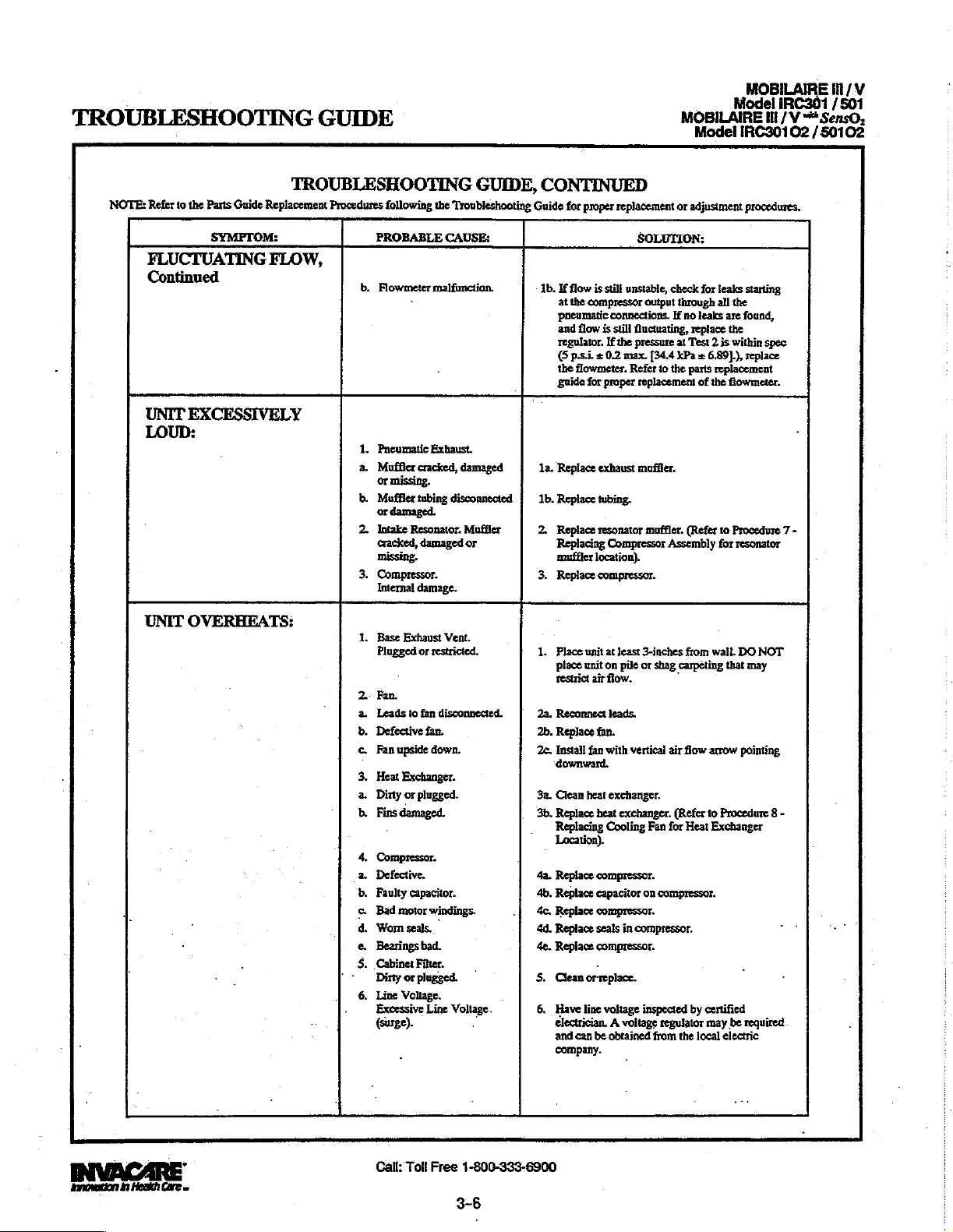
TROUBLESHOOTING
GUIDE
MOBILAIRE Ш /\У
Model
IRC301 / 501
MOBILAIRE
Model
lll / Y
IRC30102 / 50102
*SensO,
NOTE:
Refer
FLUCTUATING
Con
UNIT
LOUD:
UNIT
to
the
Parts
Guide
SYMPTOM:
tinued
EXCESSIVELY
OVERHEATS:
TROUBLESHOOTING
Replacement
FLOW,
Procedures
b.
1.
a.
b.
2.
3.
1.
2
a.
b.
с.
3.
a Dirty
b.
4.
2.
b.
©.
d.
e.
5.
*
6.
.
following
PROBABLE
Flowmeter
Pneumatic
Mufflercracked,
or
Muffler
or
Intake
cracked,
missing.
Compressor.
Internal
Base
Plugged
Fan.
Leads
Defective
Fan
Heat
Fins
-
Compressor.
Defective.
Faulty
Bad motor
Wom
Bearings
Cabinet
Dirty
Line
Excessive
(surge).
・
Exhaust.
missing.
tubing
damaged.
Resonator.
damaged
damage.
Exhaust
or
restricted.
to
fan
fan.
upside
down.
Exchanger.
or
plugged.
damaged.
capacitor.
windings.
seals.
bad.
Filter.
or
plugged.
Voltage.
Line
the
Troubleshooting
CAUSE:
malfunction.
disconnected
Vent.
disconnected.
Voltage.
GUIDE,
damaged
Muffler
or
CONTINUED
Guide
for
proper
replacement
1b.
If
flow
is
at
pneumatic
and
regulator.
G
the
guide
la.
Replace
1b.
Replace
2.
Replace
Replacing
muffler
3.
Replace
1.
Place
place
restrict
2a.
Reconnect
2b.
Replace
2c.
Install
downward.
3a.
Clean
3b.
Replace
Replacing
Location).
4a.
Replace
4b.
Replace
4c.
Replace
4d.
Replace
4e.
Replace
S.
Clean
6.
Have
electrician. A voltage
and
company.
still
the
compressor
flow
is
psi. + 0.2
flowmeter.
for
proper
exhaust
tubing.
resonator
location).
compressor.
unit
at
unit
on
air
fan.
fan
with
heat
heat
Cooling
compressor.
capacitor
compressor.
seals
compressor.
.
orreplace.
line
voltage
can
be
connections.
still
If
the
Compressor
least
flow.
leads.
exchanger.
obtained
SOLUTION:
unstable,
check
output
through
If
fluctuating,
pressure
max.
[34.4
Refer
to
the
replacement
muffler.
muffler.
Assembly
3-inches
pile
or
shag
vertical
air
exchanger.
Fan
for
on
compressor.
in
compressor.
inspected
regulator
from
or
adjustment
for
leaks
all
leaks
replace
Test 2 is
parts
replacement
of
the
(Refer
to
for
wall.
arrow
to
Procedure 8 -
Exchanger
by
certified
may
local
the
are
the
within
flowmeter.
Procedure 7 -
that
be
electric
no
at
kPa + 6.891),
from
carpeting
`
flow
(Refer
Heat
the
procedures.
starting
found,
spec
replace
resonator
DO
NOT
may
pointing
required.
>
annen
İn
Hes
CE
—
Call:
Toll
Free
1-800-333-6900
3-6

MOBILAIRE
Model
IRC301 / 501
MOBILAIRE
Ill
/V
Hl
/'V
=
SensOs
TROUBLESHOOTING
GUIDE
NOTE:
Refer
ALARMS
GOOD
P.C,
BOARD
RED:
CONTROL
RED
GREEN @ :
Purity
After
30
operates
within
panel
indicator
SensO2
GOOD
RED
ILLUMINATED
P.C.
BOARD
RED:
CONTROL
RED
GREEN):
Purity
After
30
operates normally,
within
panel
indicator
SersO2
UNIT
ALARM
P.C.
BOARD
RED:
CONTROL
RED
GREEN
_
Purity
to
the
Parts
SYMPTOM:
OXYGEN
Off
PANEL
¿Of
Switch
setting
minutes
normally,
normal
ONLY:
OXYGEN
PANEL
Off
PANEL
¿On
Switch
setting
minutes
normal
range,
ONLY:
NOT
OFF
Off
PANEL
τοι
©) : orr
Switch
setting
Guide
Replacement
AND
INDICATORS
PURITY,
LE.D,
INDICATORS:
GREEN:
off
range,
should
LED.
GREEN:
Off
INDICATORS:
YELLOW
at
73%
of
run
time,
oxygen
purity
Green
illuminate.
PURITY,
INDICATOR
INDICATORS:
Off
INDICATORS:
YELLOW:
ox
at
73%
of
run
time,
oxygen
purity
Green
should
OPERATING,
LED.
GREEN:
YELLOW:
or
iluminate.
INDICATORS:
Off
INDICATORS:
at
73%
TROUBLESHOOTING
ML:
or
85%:
unit
or
Yellow
Procedures
of
.
UNIQUE
NO
1.
following
PROBABLE
PANEL
P.C
Board.
Defective.
Of
or
85%:
unit
Yellow
or
85%.
off
.
1,
PC.
Board.
Defective.
1.
P.C.
Board.
Hom
illuminated
2.
Purity
Defective.
3.
Hom
GUIDE,
the
Troubleshooting
CAUSE:
TO
UNITS
INDICATORS
defective
Disconnected.
on
Switch.
(No
P.C.
LED’s
Board).
CONTINUED
Guide
for
WITH
THE
ILLUMINATED
1.
Replace
Unit
may
Refer
1.
Replace
Unit
may
Refer
1.
Replace
Unit
may
Refer
2.
Replace
Unit
may
Refer
3.
Reattach
proper
replacement
SENSO2
P.C.
Board.
need
retiming
to
the
timing
P.C
Board.
need
retiming
to
the
timing
P.C.
Board.
need retiming
to
the
timing
:
P.C.
Board.
need retiming
to
the
timing
horn
connector
or
SOLUTION:
FEATURE.
FOR
IRC50102
after
section
FOR
IRC50102
after
section
in
FOR
IRC50102
after
section
in
FOR
IRC50102
after
section
in
to
adjustment
board
replacement.
in
this
manual.
board
replacement.
this
manual.
board
replacement.
this
manual.
board
replacement.
this
manual.
P.C.
Board.
procedures.
ONLY
-
ONLY
-
ONLY
-
ONLY
-
Call:
Toll
Free
1-800-333-6900
3-7
innovation
στό
1)


TROUBLESHOOTING
GUIDE
MOBILAIRE
MOBILAIRE
Model
Model
IRC30102 / 50102
IRC301 / 501
IH / V
tll
m*SensO,
/V
NOTE:
Refer
to
SensO2
P.C.
BOARD
RED:
Off
CONTROL
περ
GREEN:
Green
©
with
Yellow
the
Parts
SYMPTOM:
ONLY:
L.E.D.
PANEL
:01
δι
Guide
Replacement
INDICATORS:
GREEN:
or
Off
INDICATORS:
YELLOW:
Flashing.
TROUBLESHOOTING
Procedures
Of
following
PROBABLE
1.
Transformer
a.
Molex
nected
b.
Faulty
1.
Internal
connector
from
transformer
repairs
GUIDE,
the
Troubleshooting
CAUSE:
Assembly.
discon-
P.C.
Board.
assembly.
required.
CONTINUED
Guide
for
proper
la.
Reaitach
connector.
1b.
Replace
transformer
Procedure 2 -
1.
Replace
printed
Unit
may
Refer
Call
need
to
the
Supplier
replacement
Removing
retiming
timing
for
or
SOLUTION:
assembly.
Control
circuit
board.
after
section
service.
adjustment
[Refer
Panel
For
IRCS0102
board
replacment.
in
this
manual.
procedures.
to
(SensO2)).
-
innovation
ft
Healt
Care»
Call:
Toll
Free
1-800-333-6900
3-8

TROUBLESHOOTING
GUIDE
ィ
o
U
B
L
E
5
H
o
le)
T
1
N
G
NORMAL
internal
RED:
Unit
3
"beeps"
POWER
internal
RED:
Unit
alarm
POWER
Internal
RED:
Unit
alarm
drained.
SYMPTOM:
OPERATION:
Status
Off
GREEN:
plugged
Off
unplugged,
off.
Off
plugged
off.
in,
on
start
LOSS:
Status
GREEN:
LOSS:
Status
GREEN:
in,
"Battery
Indicators:
Off
power
switch
up.
Indicators:
Off
power
switch
Indicators:
Off
power
switch
Free™
circuit
TROUBLESHOOTING
PROBABLE
No
problems.
on.
No
problems.
on,
1.
No
Power
.
on,
2.
Power
Cord.
a.
Frayed.
b.
Broken
c.
Spade
Cord
(inside
at
outlet.
or
damaged
connector
loose
or
back
of
GUIDE
CAUSE:
spade.
from
Power | 2c.Reattach
disconnected
unit).
System
"Battery
in
recharge.
1.
2a.Replace
2b.Replace
O.K.
Free
cord
and
Check
tablelamp
150-200
working,
in
home's
consult
ensure
plugged
extension
outlet
or
on
plug.
SOLUTION:
M"
Circuit
turn
power
electrical
or
VAC
check
an
that
in.
cords.
circuit.
cord.
power
connector.
outlet
voltmeter
scale.
protective
electrical
electrician.
unit
DO
Move
cord
drained.
switch
If
is
Plug
ON
with
set
outlet
isn't
device
panel
Also
properiy
NOT
use
to
another
connectors
to
a
on
or
NOTE:
REFER
TO
THE
REPAIR/REPLACEMENT
REPLACEMENT
3.
On/Off
a.
b.
switch.
Disconnected
Faulty
switch.
wire.
OR
ADJUSTMENT
GUIDE
IN
PROCEDURES
Sa.Check
to
disconnected
3b.If
on
code
time
with
the
switch
switch
switch.
switch
to
all
electrical
the
On/Off
the
concentrator
at
all
and
wiring
and
remove
and
clean
contact
switch
the
cleaner
on
and
still
doesn't
Transfer
to
new
matching
switch
wires.
does
is
wires
the
On/Off
and
turn
power
work,
wires
switch
contact.
connections
for
not
intact,
one
switch
while
tuming
off.
Reinstall
on.
replace
from
one
at a time
THIS
MANUAL
FOR
PROPER
any
come
color
at
a
If
old

TROUBLESHOOTING
GUIDE
POWER
INTERNAL
SENSO2:
Internal
RED:
Off
Alarm
Control
RED:
Off
GREEN:
operates,
Fan
compressor
SYMPTOM:
LOSS, Continued:
Status
GREEN:
may
or
Panel
YELLOW:
Off
POWER
may
not
LOSS
Indicators:
Off
not
be
Indicators:
Off
power
operating.
light
on.
TROUBLESHOOTING
PROBABLE
4,
on,
Circuit
Tripped.
5.
PC.
a.
b.
1.
Transformer
a.
b.
c.
2.
P.C.
Faulty.
breaker.
Board.
Damaged
Loose
or
Faulty.
Connector
nected.
Faulty
wiring.
Board.
CAUSE:
damaged
Assembly.
loose
GUIDE
connector
or
discon-
SOLUTION:
4.
Reset
breaker.
NOTE:
guard
power
immediately,
short
pinched
breaker
approximately 2 hours.
trips
problem.
TECHNICAL
5a.Replace
5b.Repair
1a.Replace
1b.Reattach
1c.Replace
2.
Breaker
concentrator
surge.
in
the
or
does
again,
Contact
(PROCEDURE
or
(PROCEDURE
Transformer
(PROCEDURE
Replace
DURE
Unit
P.C.
CEDURE
11).
may
Board
may
If
breaker
there
is a probable
unit.
charred
not
there
SERVICE.
replace
connector.
P.C.
require
replacement
18).
trip,
is
connector.
12).
Board
SLX
For
wires.
retiming
trip to
INVACARE
during
Check
If
run
unit
If
breaker
an
internal
11).
12).
Assembly
(PROCE-
GLX
or
(PRO-
safe-
trips
after
a
for
the
for
-
工
R
ο
υ
Β
L
同
5
H
o
o
T
|
N
G
HIGH
PRESSURE:
Internal
RED:
(LX
RED:
GREEN : Two
(Integrated
(LX
Control
RED:
GREEN:
Unit
continuous
down.
Status
On
Control
One
SMT
Panel
On
plugged
NOTE:
Indicators:
GREEN:
Board)
(1)
Flash
(2)
Sensor
Board)
Indicators:
YELLOW:
Off
in,
power
alarm.
Compressor
REFER
Off
Flashes
Board)
Off
switch
TO
THE
REPLACEMENT
on,
shut
REPAIR/REPLACEMENT
1.
P.C.
Board
Malfunction
a.
b.
Disconnected
c.
Shifting
greater
2.
4-way
a.
Not
than
Valve
Shifting.
Wire.
Valve
25
at
Pressures
p.s.i.
OR
ADJUSTMENT
GUIDE
IN
PROCEDURES
concen-
for
l/min.
max
to
flow
1a.Set
trator.
Pilot
meter
unit
Board
1b.Check
valves 1 and 2 and
on
1c.Replace
DURE
Unit
P.C.
CEDURE
2a.lf
24
shuts
tioning
4-way
THIS
MANUAL
Check
Valve 1 on
reads 0 volts
is
turned
(PROCEDURE
spade
P.C.
Board.
P.C.
11).
may
require
Board
18).
voltage
rises
volts
down,
properly.
Valve
FOR
voltage
200
volt
on,
replace
11).
connectors
connectors
Board
For
replacement
D.C.
P.C.
(PROCEDURE
(PROCE-
5LX
or
retiming
to
approximately
when
Board
Replace
PROPER
across
scale.
when
on
6LX
(PRO-
is
If
P.C.
pilot
-
after
unit
func-
16).
3-10

TROUBLESHOOTING
GUIDE
ㅜ
R
o
U
B
L
|=
5
H
o
o
T
I
N
G
HIGH
PRESSURE,
LOW
PRESSURE:
Internal
RED:
On
{LX
Control
RED:
One
GREEN : One
(Integrated
(LX
SMT
Unit
plugged
on,
continuous
pressor
due
to
shut
low
SYMPTOM:
Status
Indicators:
GREEN:
Board)
(1)
Flash
(1)
Flash
Sensor
Board)
in,
audible
down
(Failure
pressure).
Continued
On
Board)
power
switch
alarm.
to
Com-
cycie
TROUBLESHOOTING
PROBABLE
2.
b.
Bad
Coil.
3.
Sieve
Beds
Contaminated.
1.
Inlet
Filter
Dirty
or
Plugged.
2.
Compressor.
a.
Leaks
b.
Leaking
valve,
c.
Insufficient
d
Wom
3.
Heat
Exchanger
a.
Leak
ber.
b.
Inspect
exchanger.
Cup
at
CAUSE:
at
fittings
or
defective
voltage
Seals
”
tubing
tubing
-
GUIDE
SOLUTION:
2b.Replace
DURE
3.
Replace
DURE
1.
Replace
DURE
or
tubing.
relief | 2b.Repair
at
outlet.
or
Gaskets。 | 2d.Rebuild
or
body
cham- | 3a.Replace
and.
heat | 3b.Replace
2a.Replace
2c.DO
Use
(PROCEDURE
place
DURE
4-way
16).
Sieve
4).
Inlet
2).
or
repair.
leak
NOT
use
another
Top
or
retighten.
or
retighten
Heat
Exchanger
8).
Valve
Beds
Filter
or
replace.
extension
outlet.
End
of
2).
(PROCE-
(PROCE-
(PROCE-
cords.
Compressor
tubing.
Re-
(PROCE-
4,
Regulator
5.
P.E.
Valve
cracked
leaking
or
leaking.
4.
Replace
5.
Replace
age
volt
valve
approximately 1 second
the
Valve
volts.
volts
P.C.
voltage
P.E.valve
NOTE:
the
compressor
all
the
Major
pressures
adequate
sures
shut
(PROCEDURE
P.E.
at
P.E.
valve
D.C.
activates
activation
with
If
voltage
consistently,
Board.
acts
(PROCEDURE
Check
leaks
and
down.
for
pneumatic
will
to
shift
will
valve.
connector
scale.
approximately
is in
If
the
normally,
leaks
output
cause
remain
(exhaust)
cause
6).
Check
The
or
energizes
of
the
excess
replace
P.C.
starting
connections.
compressor
volt
on
P.E.
prior
4-way
of
the
Board
replace
3).
through
system
below
pres-
24
24
24
the
to
at
NOTE:
REFER
TO
THE
REPAIR/REPLACEMENT
REPLACEMENT
OR
ADJUSTMENT
GUIDE
IN
PROCEDURES
THIS
MANUAL
FOR
PROPER

TROUBLESHOOTING
GUIDE
LOW
NOTE:
using a calibrated
lyzer
OUTLET)
Internal
RED:
(LX
RED:
GREEN : One
73%
(integrated
RED:
GREEN : Two
85%
(integrated
Control
SensO2
RED:
YELLOW:
GREEN:
For
tor
will
and
continuous
system
required,
internal
RED:
(LX
Board)
Control
SensO2
RED:
YELLOW:
GREEN:
A
Yellow
purity,
user.
SYMPTOM:
CONCENTRATION:
Check
at
Test
Point 1 (OXYGEN.
of
the
Status
On
GREEN:
Control
SensO2
Control
Board)
Two
(2)
Shutdown
Sensor
Two
(2)
Shutdown
Sensor
Panel
ONLY:
On
Off
Off
units,
signal
will
be
accompanied
audible
shutdown.
Status
Off
GREEN:
or
Panel
ONLY:
Off
On
Off
indicator
but
within
Repairs
Flash
(1)
Flash
(2)
extremely
are
for
O2
purity
Oxygen
concentrator.
Indicators:
Off
Flash
Board)
Flashes
Board)
Indicators:
the
alarm
Repairs
Indicators:
Off
Integrated
Indicators:
signals
specification
required.
Red
low
Ana-
indica:
purity
and
Sensor
for
by
are
low
TROUBLESHOOTING
PROBABLE
1.
Cabinet
2.
Inlet
Filter
3.
Compressor.
a.
Defective.
b.
Faulty
c.
Bad
d.
Worm
e.
Bad
$.
Leakatfitings
g.
Leaky
Vaive.
h.
Insufficient
4,
Heat
Exchanger.
a.
Leak
・
a
a
the
ber.
b.
Inspect
Exchanger.
5.
Regulator
6.
Exhaust
7.
Fan
a.
Not
ing.
b.
Faulty
8.
Sieve
9.
Tubing
10.P.C.
Board
a.
Shifts
b.
Pressure
leaks.
Filters
Dirty.
Dirty.
Capacitor.
Motor
Windings.
Seals.
Bearings.
or
Defective
voltage
at
tubing
tubing and
Cracked
Muffler
Operating.
Fan.
Beds
defective
kinked
or
at
wrong
transducer
CAUSE:
or
tubing.
(outlet).
or
body
or
Leaking.
dirty
or
plugged.
Unit
overheat-
blocked.
pressures.
GUIDE
Relief
cham-
Heat
tubing
SOLUTION:
1.
Clean
2).
2.
Replace
3a.Replace
DURE
3b.Replace
DURE
3c.Replace
DURE
Sd.Rebuild
sor
(PROCEDURE
3e.Replace
DURE
Sf.
Replace
3g.Replace
」
3h.DO
4b.Replace
5.
6.
7a.Leads
7b.Replace
8.
9.
10a.Check
10b.Inspect
NOT
4a.Replace
Replace
CEDURE
Replace
Replace
Reconnect
Replace
Repair
Pressure
at
shift
Board
at
product
ONLY
(PROCEDURE
or
Replace
(PROCEDURE
Compressor
7).
Capacitor
7).
Compressor
7).
Top
Compressor
7).
Fittings
Relief
use
or
Heat
(PROCEDURE
(PROCEDURE
to
fan
(PROCEDURE
(PROCEDURE
or
replace.
pressure
point.
(PROCEDURE
tubing
if
(PROCEDURE
End
or
Valve.
extension
Retighten.
or
retighten
Exchanger
8).
Disconnected.
(PROCEDURE
at
should
If
not,
at
tank.
damage
2).
(PROCE-
(PROCE-
(PROCE-
of
Compres-
2).
(PROCE-
Tubing.
cords.
tubing.
(PRO-
6).
2).
10).
10).
4).
product
rise
transducer
Replace
9).
tank.
to
20
p.s.i.
replace
21).
tubing
is
evident.
・
|
P.C.
and
NOTE:
REFER
TO
THE
REPLACEMENT
REPAIR/REPLACEMENT
OR
ADJUSTMENT
3-12
GUIDE
IN
PROCEDURES
THIS
MANUAL
FOR
PROPER
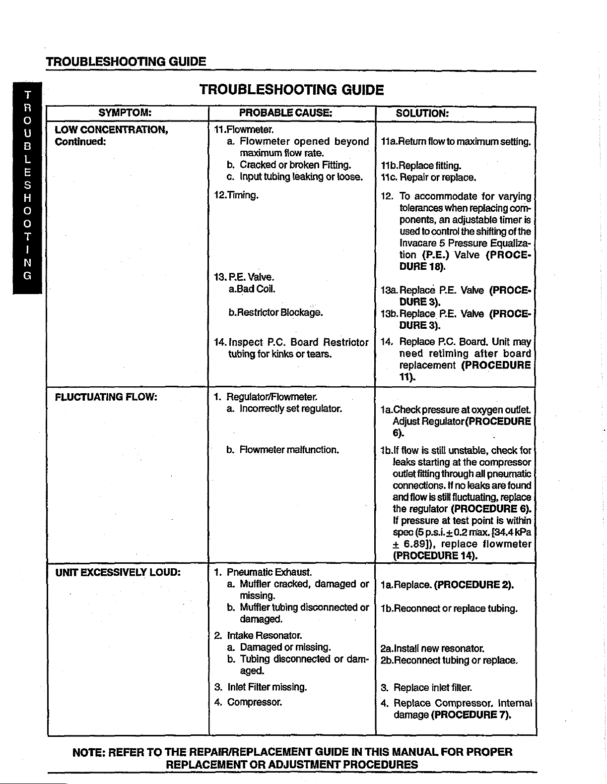
TROUBLESHOOTING
GUIDE
T
5
U
B
L
5
日
o
o
T
1
N
G
LOW
CONCENTRATION,
Continued:
FLUCTUATING
SYMPTOM:
FLOW:
TROUBLESHOOTING
PROBABLE
11.Flowmeter.
a.
Flowmeter
maximum
b.
Cracked
c.
Input
tubing
12.Timing.
13.
RE.
Valve.
a.Bad
Coil.
b.Restrictor
14.inspect
tubing
for
1.
Regulator/Flowmeter.
a.
Incorrectly
CAUSE:
opened
flow
or
broken
leaking
Blockage.
|
P.C.
Board
kinks
or
set
GUIDE
beyond | 11a.Retum
rate.
Fitting.
or
loose.
“
Restrictor | 14.
tears.
regulator.
SOLUTION:
11b.Replace
|
110.
Repair
12.
To
accommodate
tolerances
ponenis,
used
Invacare 5 Pressure
tion
DURE
13a.Replace
DURE
13b.Replace
DURE
Replace
need
teplacement
11).
1a.Check
Adjust
6).
fiow
to
maximum
fitting.
or
replace.
when
replacing
an
adjustable
to
control
(P.E.)
18).
3).
3).
retiming
pressure
Regulator(PROCEDURE
Valve
P.E.
PE.
P.C.
Board.
the
Valve
Valve
at
(PROCEDURE
setting.
for
varying
timer
shifting
of
Equaliza-
(PROCE-
(PROCE-
(PROCE-
Unit
after
board
oxygen
outlet.
、
com-
is
the
may
UNIT
EXCESSIVELY
LOUD:
b.
Flowmeter
1.
Pneumatic
a.
Muffler
missing.
b.
Muffler
damaged.
2.
Intake
a.
Damaged
b.
Tubing
aged.
3.
Inlet
4.
Compressor.
Resonator.
Filter
malfunction.
Exhaust.
cracked,
tubing
or
disconnected
missing.
damaged
disconnected
missing.
or
dam- | 2b.Reconnect
1b.1f
flow
is
still
unstable,
leaks
starting
outlet
fitting
connections.
and
flow
the
regulator
If
pressure
spec
(5
+
6.89]),
(PROCEDURE
or | 1a.Replace.
or | 1b.Reconnect
2a.Install
8.
4,
new
Replace
Replace
damage
at
through
if
no
is
still
fluctuating,
(PROCEDURE
at
test
p.s.i.+
0.2
replace
14).
(PROCEDURE
or
replace
resonator.
tubing
inlet
filter.
Compressor.
(PROCEDURE
check
the
compressor
all
pneumatic
leaks
point
max.
flowmeter
tubing.
or
replace.
are
found
replace
is
within
{34.4
kPa
2).
Internal
7).
for
6).
NOTE:
REFER
TO
THE
REPLACEMENT
REPAIR/REPLACEMENT
OR
ADJUSTMENT
GUIDE
IN
THIS
PROCEDURES
MANUAL
FOR
PROPER
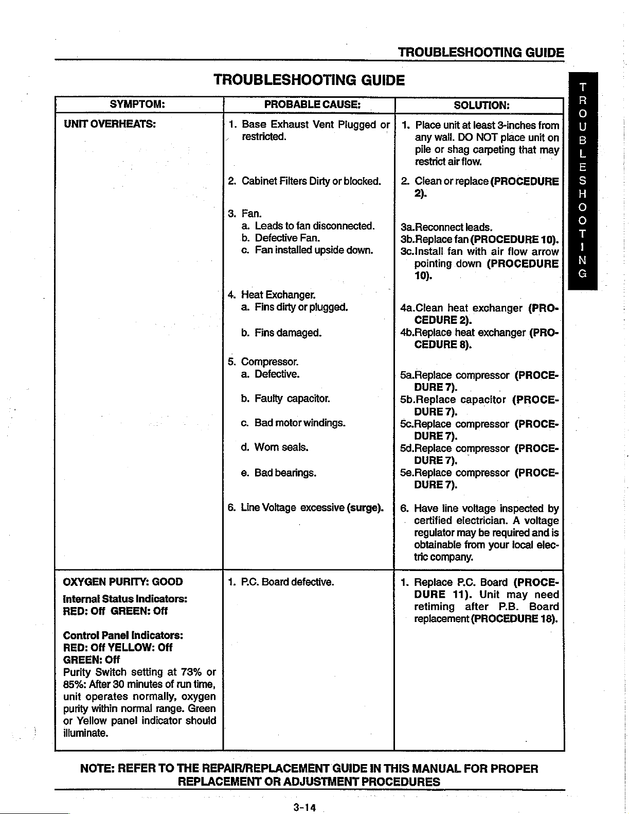
TROUBLESHOOTING
GUIDE
UNIT
SYMPTOM:
OVERHEATS:
TROUBLESHOOTING
PROBABLE
1.
Base
restricted.
2.
Cabinet
3.
Fan.
a.
Leads
b.
Defective
c.
Fan
4.
Heat
Exchanger.
a.
Fins
b.
Fins
5.
Compressor.
a.
Defective.
b.
Faulty
c.
Bad
d.
Worn
e.
Bad
Exhaust
Filters
to
installed
dirty
damaged.
capacitor.
motor
seais.
bearings.
CAUSE:
Vent
Dirty
fan
disconnected.
Fan.
upside
or
plugged.
windings.
Plugged
or
blocked.
down.
GUIDE
or
SOLUTION:
1.
Place
unit
any
wail.
DO
pile
or
shag
restrict
2.
Clean
2).
3a.Reconnect
3b.Replace
3c.Install
pointing
10).
4a.Clean
CEDURE
4b.Replace
CEDURE
5a.Replace
DURE
5b.Replace
DURE
5c.Replace
DURE
5d.Replace
DURE
5e.Replace
DURE
air
or.
replace
fan
fan
down
heat
2).
heat
compressor
7).
7).
compressor
7).
compressor
7).
compressor
7).
at
least
3-inches
NOT
place
carpeting
flow.
(PROCEDURE
leads,
(PROCEDURE
with
air
(PROCEDURE.
exchanger
exchanger
8).
capacitor
unit
that
flow
arrow
(PRO-
(PRO-
(PROCE-
(PROCE-
(PROCE-
(PROCE-
(PROCE-
from
on
may
10).
T
R
ο
U
B
L
同
S
H
ο
ο
T
|
N
G
OXYGEN
Internal
RED:
Control Panel
RED:
GREEN:
Purity
85%:
unit
purity
or
Yellow
illuminate.
PURITY:
Status
Off
GREEN:
Off
YELLOW:
Off
Switch
After
30
operates
within
panel
NOTE:
GOOD
Indicators:
Off
Indicators:
Off
setting
minutes
normally,
normal
REFER
range.
indicator
TO
at
73%
or
of
run
time,
oxygen
Green
should
THE
REPAIR/REPLACEMENT
REPLACEMENT
6.
Line
Voltage
1.
Р.С.
Board
|
OR
excessive
defective.
GUIDE
ADJUSTMENT
(surge).
IN
THIS
PROCEDURES
6.
Have
line
certified
regulator
obtainable
tric
company.
1.
Replace
DURE
retiming
replacement
voltage
electrician. A voltage
may
from
P.C.
11).
after
inspected
be
required
your
local
Board
Unit
(PROCEDURE
(PROCE-
may
P.B.
and
elec-
need
Board
MANUAL
FOR
PROPER
by
is
18).
3-14

TROUBLESHOOTING
GUIDE
T.
R
о
U
B
L
Ε
S
H
o
о
T
I
N
G
SYMPTOM:
UNIT
NOT
ALARM:
Internal
RED:
Off
GREEN:
CONTROL
RED:
Off
YELLOW:
GREEN:
Purity
Switch
UNIT
NOT
Internal
RED:
Off
GREEN:
Control
RED:
Off
YELLOW:
GREEN:
Power
audible
UNIT
NOT
Internal
RED:
Three
GREEN:
(Integrated
OPERATING
OFF
Status
Off
PANEL
Off
Off
setting
OPERATING,
Status
Off
Panel
Indicators:
Off
Off
Switch
alarm.
OPERATING,
Status
(3)
One
(1)
Circuit
Indicators:
INDICATORS:
at
73%
or
Indicators:
ON.
Continuous
Indicators:
Flashes
Flash
Board)
85%.
TROUBLESHOOTING
PROBABLE
1.
Purity
Switch.
Defective.
. | 2.
Нот.
Disconnected.
1.
Transformer
a.
Molex
from
b.
Faulty
1.
Internal
CAUSE:
Assembly.
connector
P.C.
Board.
transformer
repairs
required.
GUIDE
disconnected
assembly.
SOLUTION:
1.
Replace
DURE
retiming
(PROCEDURE
2.
Reattach
hamess.
1a.Reattach
1b.Replace
(PROCEDURE
1.
Replace
(PROCEDURE
11).
after
P.C.
Board.
Unit
may
board
replacement.
18).
horn
connector
connector.
transformer
12).
SensO2
circuit
11).
(PROCE-
need
to
assembly
board
Control
RED:
YELLOW:
GREEN:
Panel
Off
Flashing
On
NOTE:
Indicators:
REFER
TO
THE
REPAIR/REPLACEMENT
REPLACEMENT
OR
ADJUSTMENT
GUIDE
IN
PROCEDURES
THIS
MANUAL
FOR
PROPER

PROCEDURE
3
P.
E.
VALVE
PROCEDURE 3 -REPLACING
TO
PREVENT
ELECTRICAL
MU
M<r><
Unplug
>
Remove
Remove
oP
Remove
Remove
oP
If
PE.
contamination.
6.
Install
“
NOTE:
OF
THE
7.
Run
unit.
Valve
new
After
INVACARE 5 CONCENTRATOR.
unit
ELECTRICAL
OUTLET
cabinet
spade
ty-wraps
P.E.
is
(Refer
connectors
valve
not
to
P.E.
valve
from
assembly
replacing
and
check
for
BEFORE
to
PROCEDURE
from
P.E.
Valve
be
installed
assembly
P.E.
valve,
leaks
PE.
VALVE
SHOCK,
SERVICING.
P.E.
Valve
tubing.
from
tubing.
immediately,
immediately,
retiming
(Refer
to
-5LX/5LXO2/5LXO2T;
CAUTION
ALWAYS
1 - REMOVING
assembly.
CAUTION
by
may
PROCEDURE
DISCONNECT
plug
the
reversing
be
necessary.
STEPS
19 - LEAK
CABINET).
P.E.
16LXO2/6LXO2T
CONCENTRATOR
Valve
Refer
tubing
3-5.
to
PROCEDURE
to
:
TEST).
ONLY
prevent
18 - TIMING
|
(FIGURE
FROM
sieve
bed
1)
8.
Reinstall
cabinet
(Refer
to
PROCEDURE
1 -
REMOVING
Assembly
CABINET).
P.
Spade
Connectors
E.
Valve
Ty-Wrap
|
Tubing
Sieve
Beds
(SHOWN
FIGURE 1 -
REPLACING
P.E.
VALVE
(5LX/SLXO2/SLXO2T/6LXO2/6LXO2T
4-1
for
Reference)
ONLY)
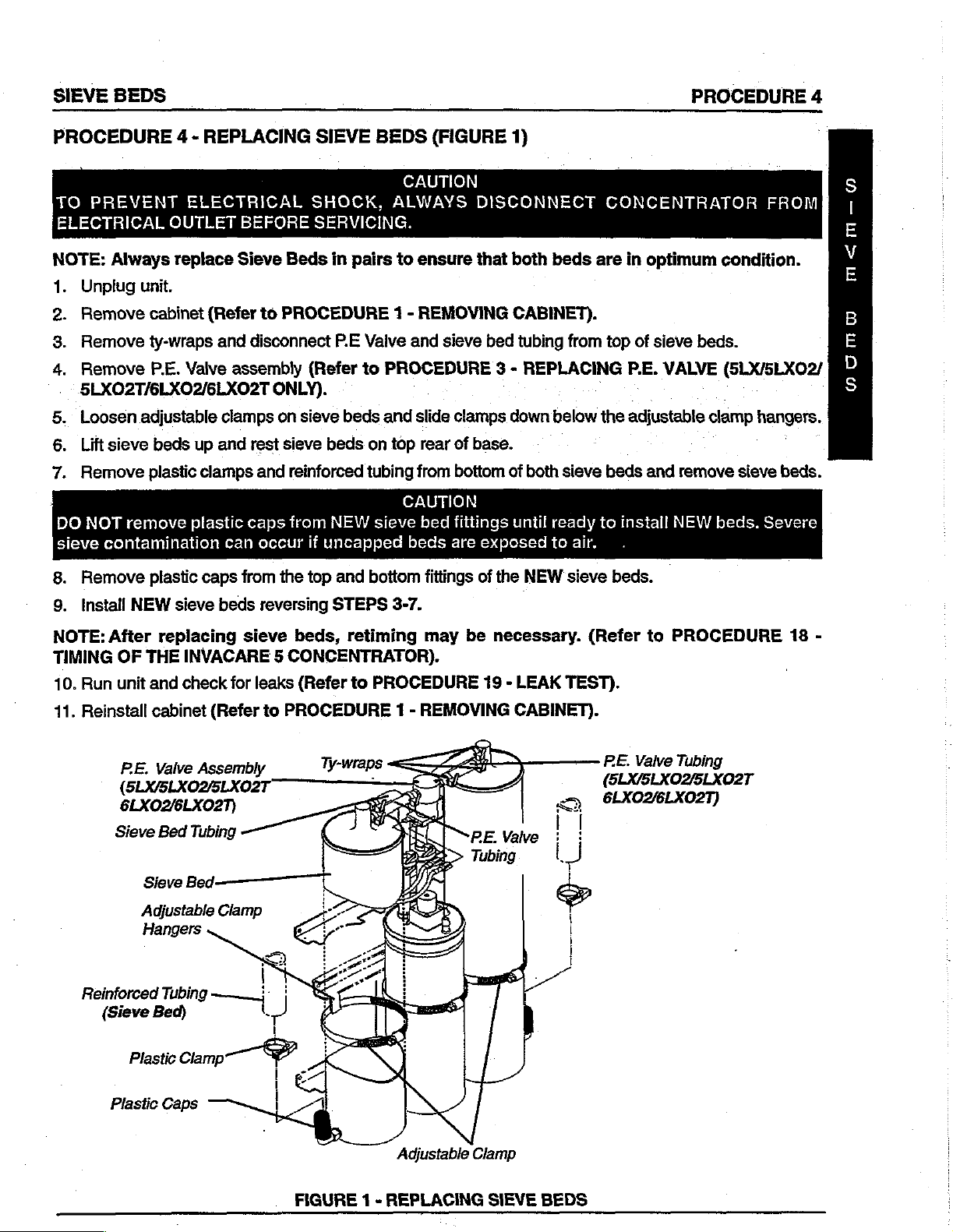
SIEVE
BEDS
PROCEDURE
4
PROCEDURE
TO
PREVENT
ELECTRICAL
NOTE:
1.
2.
3.
4.
Always
Unplug
Remove
Remove
Remove
4 - REPLACING
OUTLET
replace
unit.
cabinet
ty-wraps
PE.
5LX02T/6LX02/6LXO2T
Loosen
Lift
の a
Remove
DO
sieve
Remove
8.
NOT
adjustable
sieve
beds
plastic
remove
contamination
plastic
ELECTRICAL
BEFORE
Sieve
(Refer
Valve
to
and
disconnect
assembly
clamps
up
and
rest
clamps
plastic
caps
can
from
and
caps
occur
SIEVE
SHOCK,
SERVICING.
Beds
in
PROCEDURE
P.E
(Refer
ONLY).
on
sieve
sieve
beds
reinforced
from
NEW
if
uncapped
the top
and
pairs
Vaive
to
beds
on
tubing
sieve
bottom
BEDS
(FIGURE
CAUTION
ALWAYS
to
ensure
1 - REMOVING
and
sieve
PROCEDURE
and
slide
top
rear
from
CAUTION
bed
beds
fittings
DISCONNECT
that
bed
3 - REPLACING
clamps
of
base.
bottom
fittings
are
of
exposed
of
the
1)
both
beds
CABINET).
tubing
down
until
both
ready
to
NEW
from
below
sieve
air.
sieve
CONCENTRATOR
are
in
optimum
top
of
sieve
P.E.
VALVE
ーー
the
adjustable
beds
and
remove
to
install
NEW
beds.
condition.
beds.
(5LX/5LXO2/
clamp
hangers.
sieve
beds.
FROM
02
m<am_-
(o)
beds.
Severe
Install
9.
NOTE:
TIMING
10.
Run
11.
Reinstall
Reinforced
NEW
sieve
beds
After
OF
unit
PE.
THE
replacing
INVACARE 5 CONCENTRATOR).
and
check
cabinet
Valve
(Refer
Assembly
(5LX/5LX02/5LX02T
6LXO2/6LXO2T)
Sieve
Bed
Tubing
Sieve
Bed:
Adjustable
Hangers
Clamp
Tubing
(Sieve
Bed)
reversing
sieve
for
leaks
to
oi
A)
|
STEPS
beds,
(Refer
retiming
to
PROCEDURE
3-7.
may
PROCEDURE
1 - REMOVING
be
necessary.
19 - LEAK
CABINET).
TEST).
«y
(Refer
PE.
to
PROCEDURE
Valve
Tubing
(SLX/SLXO2/5LXO2T
6LXOZ/6LXO2T)
18
-
Adjustable
FIGURE 1 -
REPLACING
Clamp
SIEVE
BEDS

PROCEDURE
5
CHECK
VALVES
PROCEDURE
TO
ELECTRICAL
1.
AOMZO
mb-
U
Unplug
2.
Remove
NOTE:
one-way
direction
3.
Loosen
access
4.
Remove
tubing.
The
printed
of
the
erly
PREVENT
OUTLET
unit.
cabinet
Replace
directional
ONLY.
adjustable
check
ty-wraps
check
installed.
on
check
valves
the
valve.
5 - REPLACING
ELECTRICAL
BEFORE
(Refer
one
valve(s).
are
bottom
Low
or
both
and
clamp
from
one-way
half
system
to
PROCEDURE
check
can
on
top
and
o
of
CHECK
SHOCK,
SERVICING.
valves
be
checked
product
the
tank
bottom
directional
check
pressures
VALVES
CAUTION
ALWAYS
1 - REMOVING
when
by
passing
and
slide
of
the
check
CAUTION
and
valves
and
and
(FIGURE
DISCONNECT
performing
air
clamp
valve(s)
MUST
eventual
be
should
bed
1)
CABINET)
this
procedure.
through
down
below
and
disconnect
installed
be
installed
contamination
CONCENTRATOR
The
them.
correctly.
Air
the
adjustable
check
with
The
VAC
will
check
should
clamp
valve(s)
letters
to
the
result
FROM
valves
flow
in
one
hanger
from tygon
VAC
underside
if
not
prop-
are
to
are
5.
Install
NOTE:
6..
NOTE:
check
7.
8.
Ensure
Secure
If
valve(s).
Run
unit
Reinstall
Underside
Check
the
NEW
the
tygon
and
cabinet
Valve
proper
check
tubing
check
of
check
valve(s)
orientation
valve(s)
is
damaged
for
leaks
(Refer
to
Check
Tygon
into
the
tygon
of
by
installing
in
(Refer
check
any
valves
new
ty-wraps
way,
to
PROCEDURE
PROCEDURE 1 -
Vaive
Tubing
tubing.
when
to
replace
the
REMOVING
Check
Valve
installing.
the
tygon
tubing
section
19 - LEAK
CABINET).
Ty-wraps
(2
per
Check
Valve).
where
of
tygon
TEST).
Product
previously
tubing before
Tank
removed.
installing
.
Adjustable
Clamp
FIGURE 1 -
REPLACING
4-3
CHECK
VALVES

REGULATOR
PROCEDURE
6
PROCEDURE
Replacing
TO
PREVENT
ELECTRICAL
Unplug
=
Remove
ND
Loosen
©
AR
Puli
product
Remove
Remove
pa
NOTE:
regulator
Ensure
front
Clean
proper
of
unit
are
6 - REPLACING / ADJUSTING
Regulator
ELECTRICAL
OUTLET
unit.
cabinet
adjustable
tank
the
four
regulator
mounting
installed
installation
or
flow
(FIGURE
BEFORE
(Refer
clamp
back
and
(4)
mounting
from
surface
onto
will
be
SHOCK,
SERVICING.
to
PROCEDURE
on
product
up
to
screws
product
of
the
ports
of
regulator.
interupted
1)
access
tank
product
REGULATOR
CAUTION
ALWAYS
1 - REMOVING
tank
and
slide
regulator.
that
secure
cap
ensuring
tank
lid.
(underside)
CAUTION
Note
flow
causing
system
DISCONNECT
CABINET).
clamp
regulator
that
the
Ensure
of
the
NEW
arrow
on
shutdown.
down
below
to
product
"O" rings are
that
the
two
regulator
regulator.
CONCENTRATOR
the
adjustable
]
tank
cap.
removed.
(2)
"O"
rings
before
This
installation.
MUST
face
FROM
.
clamp-hanger.
for
the
NEW
toward
the
DOaArPrrcoma
7.
Install
8.
Torque
9.
Re-install
10.
Adjust
new
mounting
regulator
PROCEDURE).
11.
Run
unit
12.
Reinstall
Adjustable
regulator
product
pressure
and
check
cabinet
onto
screws
tank
and
for
leaks
(Refer
to
Mounting
(To
Bottom
Regulator).
Clamp
product
to 5 + 1
if
tank
inch
secure
necessary
(Refer
PROCEDURE
Screws
“O”
Rings
of
by
lbs.
with
the
(Refer
to
PROCEDURE
reversing
adjustable
STEP
clamp.
to
ADJUSTING
19 - LEAK
1 - REMOVING
5.
REGULATOR
TEST).
CABINET).
(FIGURE
Regulator
Flow
Arrow
2)
in
this
Sieve
Beds
(for
Reference
FIGURE 1 -
REPLACING
REGULATOR
only.)

PROCEDURE
6
|
REGULATOR
PROCEDURE
Adjusting
1.
Tum
2.
Install
NOTE:
not
in
5
p.si. + 0.5
sure
İTO
DOAPrcoOma
ELECTRICAL
3.
Unplug
4.
Remove
5,
Move
REGULATOR
6.
Plug
7.
Locate
6 - REPLACING
Regulator
unit
ON.
pressure
Check
specification,
does
PREVENT
p.s.i.,
fall
unit.
cabinet
product
unit
in
the
02
pressure
within
ELECTRICAL
OUTLET
tank
-
and
pressure
(FIGURE
gauge
refer
Replacing
turn
onto
oxygen
at
oxygen
proceed
to
specification,
BEFORE
(Refer
back
power
adjustment
to
the
TROUBLESHOOTING
to
PROCEDURE
to
access
Regulator
switch
/
ADJUSTING
2)
outlet.
outlet.
STEP
SHOCK,
SERVICING.
3.
operate
regulator
ON.
screw
If
ALWAYS
[FIGURE
in
center
REGULATOR
It
should
difficulty
normally.
CAUTION
1 - REMOVING
(Refer
read a steady 5 p.s.i.+0.5
GUIDE
to
1).
of
regulator.
is
encountered
in
this
DISCONNECT
CABINET).
PROCEDURE
p.s.i.
If
in
adjusting
manual
6 - REPLACING/ADJUSTING
for
CONCENTRATOR
or
maintaining
assistance.
pressure
If
pres-
FROM
is
8.
Insert a 3/32-inch
9.
While
a)
b)
10.
reading
Clockwise
Counterclockwise
Reinstall
cabinet
Product
Adjustable
Allen
pressure
to
increase
(Refer
Tank
Clamp
wrench
gauge,
to
decrease
to
into
turn
output
PROCEDURE
pressure
output
—
|
the
pressure
pressure
or;
pressure.
1 -
adjustment
adjustment
REMOVING
screw.
screw:
CABINET).
Pressure
Screw
(3/32-inch
Alfen
Wrench).
Adjustment
‘Sieve
Beds
(Removed
for
Clarity)
FIGURE 2 -
ADJUSTING
REGULATOR

COMPRESSOR
PROCEDURE
7
PROCEDURE
TO
PREVENT
DISCONNECT
TRICAL
Replacing
1.
2.
3:
NOTE:
compressor
been
4.
5.
OUTLET
Unplug
Remove
REMOVING
.Disconnect
compressor
Leave
removed
Disconnect
assembly.
Disconnect
from
back
grommet.
7 - REPLACING
CAUTION
ELECTRICAL
CONCENTRATOR
BEFORE
Compressor
unit.
cabinet
assembly
of
(Refer
CABINET).
intake
assembly.
intake
from
concentrator.
molex
ground
sound
SHOCK,
SERVICING.
Assembly
to
PROCEDURE
and
exhaust
resonator
until
compressor
connector
(green)
box
wire
and
]
COMPRESSOR
ALWAYS
FROM
(FIGURE
from
(NOT
pull
ELEC-
hoses
intact
compressor
SHOWN)
wire
through
1)
1
-
from
on
has
ASSEMBLY
6.
Cut
7.
Remove
compressor
8.
Tilt
and
NOTE:
Replacing
9.
Remove
sor
10.
Reverse
assembly.
11.
Run
CEDURE
12.
Reinstall
REMOVING
Intake
Resonator
OR
and
remove
the
four
brackets
compressor
lift
out.
If
replacing
Capacitor
intake
and
install
unit
onto
STEPS
and
inspect
19 - LEAK
cabinet
CABINET).
CAPACITOR
ty-wraps.
(4)
mounting
to
base.
assembly
capacitor
(FIGURE
resonator
3-8
(Refer
from
NEW
to
install
for
leaks
TEST).
to
Grommet
screws
toward
compressor.
PROCEDURE
front
only,
proceed
2).
existing
new
compressor
(Refer
Ground
Wire
securing.
of
unit’
to
compres-
to
PRO-
-
1
-
(Green)
DONUOUMDITZOO
Compressor
Replacing
1.
Remove
pressor
2.
Remove
3.
Disconnectthe
4.
Remove
pressor
5.
Install
6.
[fapplicable,
the
7.
Reconnect
nectors
Mounting
Capacitor
Assembly
terminal
ty-wraps
Mounting
NEW
OLD
on
Screws
(FIGURE
compressor.
(FIGURE
boot
on
wires
to
and
capacitor
Bracket.
capacitor
transfer
capacitor
spade
capacitor.
by
the
to
the
connectors
Е
FIGURE
(Refer
wires
the
capacitor.
reversingSTEPS
unterminated
NEW
1 -
2)
to
Replacing
1).
(if
present).
from
bottom
capacitor.
from
compressor
Tilt
Compressor
Forward
Remove.
REPLACING
Com-
of
Com-
2-4.
terminals
from
to
con-
and
COMPRESSOR
8.
Reinstall
Replacing
Compressor
Mounting
Bracket
Capacitor.
Ty-wraps
ASSEMBLY
compressor
Compressor
q ん
ОЗС
FIGURE 2 -
REPLACING
Exhaust
(NOT
assembly.
Assembly)
—
CAPACITOR
Hose
SHOWN)
(Refer
(FIGURE
Remove/
Come
Me
ere.
to
1).

PROCEDURE
8
HEAT
EXCHANGER
PROCEDURE
H
E
A
TO
ELECTRICAL
T
E
1.
X
2.
σ
3.
H
A
N
NOTE:
G
4.
同
If
5.
6.
7.
PREVENT
Unplug
Remove
Remove
BLY
unit.
cabinet
compressor
OR
CAPACITOR).
Concentrator
Cut
the
four
the
sound
applicable,
Loosen
and
Move
Remove
the
rear
the
of
heat
8 - REPLACING
ELECTRICAL
OUTLET
(4)
ty-wraps
box.
use
care
adjustable
the
heat
heat
exchanger
exchanger.
BEFORE
(Refer
assembly
can
not
exchanger.
to
PROCEDURE
be
laid
that
to
damage
clamps
out
HEAT
SHOCK,
SERVICING.
(Refer
down
secure
to
fins
on
the
access
the
EXCHANGER
CAUTION
ALWAYS
1 -
REMOVING
to
PROCEDURE
to
more
easily
heat
exchanger
CAUTION
of
heat
exchanger
compressor
the
hoses
(FIGURE
DISCONNECT
access
to
when
output
and
remove
1)
CABINET).
7 - REPLACING
heat
exchanger.
the
four
(4)
ty-wrap
installing,
and
valve
manifold
them
from
CONCENTRATOR
COMPRESSOR
mounts
removing
the
input
heat
exchanger.
or
hoses
FROM
ASSEN-
under
the top
cleaning.
at
the
of
front
,
8.
9.
10.
11.
12.
Ensure
that
exchanger
Reverse
Torque
Run
Reinstall
STEPS
adjustable
unit
and
cabinet
protective
is
being
installed,
4-6
clamps
check
for
(Refer
(paper)
to
install
leaks
to
Ty-wrap
(Removed
DO
cover
discard
new
heat
to
heat
exchanger
(Refer
PROCEDURE
Mounts
NOT
REMOVE.)
is
installed
protective
exchanger.
to
to
PROCEDURE
1 -
REMOVING
(4)
for
Clarity
ONLY.
onto
paper
6.5 + 1
the
front
cover.
inch
Ibs.
19 - LEAK
CABINET).
of
finned
heat
TEST).
Adjustable
Compressor
(To
Heat
Compressor.)
exchanger.
Clamp
Output
Exchanger
Hose
from
If
NEW
heat
Valve
Manifold
Ty-wraps
(4)
Heat
Exchanger.
present
on
all
NOTE:
models,
Fins
FIGURE 1 -
not
Protective
necessary
REPLACING
(Paper)
for
HEAT
(From
unfinned
EXCHANGER
Valve
Cover.
models.
Heat
Manifold.)
NOTE:
Input
Hose
Exchanger
Protective
to
4-way
paper
cover
not
4-7

CONTROL
PANEL
PROCEDURE
9
PROCEDURE
TO
PREVENT
ELECTRICAL
=
Unplug
Remove
Remove
ON
Loosen
Cut
ap
the
tubing
Remove
from
Disconnect
Disconnect
Disconnect
оно
10.
Remove
ness
from
41.
Remove
9 - REMOVING
ELECTRICAL
OUTLET
unit.
cabinet
the
two
the
two
(2)
ty-wraps
the
top
the
1/4-inch
the
9-pin
the
8-pin
the
4-pin
and
code
On/Off
control
panel.
BEFORE
(Refer
(2)
that
to
upper
lower
secures
of
the
I.D.
mounting
pressure
molex
molex
connector
connectors
switch
CONTROL
SHOCK,
SERVICING.
PROCEDURE
mounting
screws
the
1/8-inch
product
tank.
regulator
connector
connector
to
interface
from
circuit
to
circuit
PANEL
CAUTION
ALWAYS
1 - REMOVING
screws
that
from
P.C.
from
P.C.
cable
breaker,
breaker
that
secure
secure
I.D.
transducer
tubing
Board.
Board.
from
hour
does
(FIGURE
DISCONNECT
CABINET).
the
control
the
control
tubing
from
the tee
P.C.
Board
meter
not
have
1)
panel.
panel.
to
fitting
(Telemetry
and
On/Off
to
be
removed).
CONCENTRATOR
the
product
behind
Unit
switch.
the
control
ONLY).
(Jumper
tank
FROM
and
remove
panel.
wire
가우
|
har-
12.
Reverse
13.
Run
unit
LEAK
14.
Reinstall
Circuit
(8
,
(On/Off
to
Breaker.)
Wi
umper
Switch
Circuit
8-Pin
1/4"
Tubing
Tank,
STEPS
and
TEST).
cabinet
Breaker
Amp)
Wire
Connector
|.D.
Regulator
(To
)
3-10
to
check
à
for
(Refer
TK
Produ
re-install
leaks
to
PROCEDURE
On/Off
control
at
transducer
Switch
panel.
tubing
1 - REMOVING
ittij
Fitting
on
product
tank
cap
CABINET).
Upper
(2
ea. - 1
一
1/8"
LD.Transducer
duet
P.
(To
o
Tank)
Produc.
(Refer
Mounting
per
一
Control
to
PROCEDURE
Screws
side.)
Panel
(Lower
Control
Lower
Mounting
-
ea,
(2
1
per
19
front
of
Panel.)
Screws
side.)
-
FIGURE 1 -
REMOVING
CONTROL
PANEL
 Loading...