


KSS SEA TING SYSTEM
CHILD/JUNIOR SIZES: 10R, 12R, 14R, 16R
ADUL T SIZES: 16T, 18T, 20T
STORM JR. TRANSPORT READY OPTION (TRRO) 12R, 14R, 16R
Assembly, Installation, and Operating Instructions
SPECIAL NOTES
WHEELCHAIR TIE-DOWN RESTRAINTS AND SEA T RESTRAINTS Invacare recommends that wheelchair
users NOT be transported in vehicles of any kind
while in wheelchairs. As of this date, the Department of Transportation has not appr oved any tiedown systems for transportation of a user while in
a wheelchair, in a moving vehicle of any type.
It is Invacare’s position that users of wheelchairs
should be transferred into appropriate seating in
vehicles for transportation and use be made of
the restraints made available by the auto
industry. Invacare cannot and does not recommend any wheelchair transportation systems.
AS REGARDS RESTRAINTS - SEAT POSITIONING
STRAPS - IT IS THE OBLIGATION OF THE DME DEALER,
THERAPISTS AND OTHER HEALTH CARE PROFESSIONALS TO DETERMINE IF A SEAT POSITIONING STRAP IS
REQUIRED TO ENSURE THE SAFE OPERA TION OF THIS
EQUIPMENT BY THE USER. SERIOUS INJURY CAN OCCUR IN THE EVENT OF A F ALL FROM A WHEELCHAIR.
SAFETY SUMMARY
WARNING
DO NOT install this equipment without first reading and understanding this instruction sheet. If you
are unable to understand the W ARNINGS, CAUTIONS and INSTRUCTIONS, contact a health-care
professional , dealer or technical personnel before attempting to install this equipment - otherwise, injury or damage may occur .
Ensure that the seat is fixed to the wheelchair. A
loose seat may lead to potentially dangerous
situations with positioning devices.
It is strongly recommended that the lap belt be
strapped across the hip area with an angle of
o
45
to the seating surface. Angles less than 45
make it easier for the user to slip under the belt if
it is improperly tightened.
NOTE: The KSS seating system is defined as a
seating system which includes the following:
o
CHILD/ STORM Jr .
JUNIOR ADUL T (TRRO)
10R, 12R, 16T,18T 12R, 14R
FEATURES 14R, 16R 20T 16R
Curved Back Standard Standard Standard
Ulti-Mate Base Standard Standard Standard
Neck Support Standard Standard Standard
Lateral Supports:
Fixed Standard Standard Standard
Swingaway Optional Optional Optional
Growth Bracket: Standard N/A Standard
900 Angle Standard Standard Standard
Adj. Angle Optional Optional N/A
Lap Belt Standard Standard Standard
Twist Release
Cane Clamp Standard Standard Standard
Quick Release
Rail Clamp Standard Standard Standard
Abductor Optional Optional Optional
Shoulder Support Optional Optional Optional
ATTACHING/ADJUSTING THE
FIXED GROWTH BRACKET
NOTE: This procedure only applies the Child/Junior Sizes.
All other procedures are applicable to both the Child/
Junior and Adult Sizes.
Attaching the Growth Bracket
NOTE: Additional mounting hooks and mounting screws
are supplied for the Ulti-Mate Seat and Curved Back.
This additional hardware is taking the place of the growth
bracket.
1. Remove the curved back, Ulti-Mate Base, and growth
bracket from their respective packages.
2. Unzip center panel of the back cover, exposing the
six (6) T-nutted mounting holes.
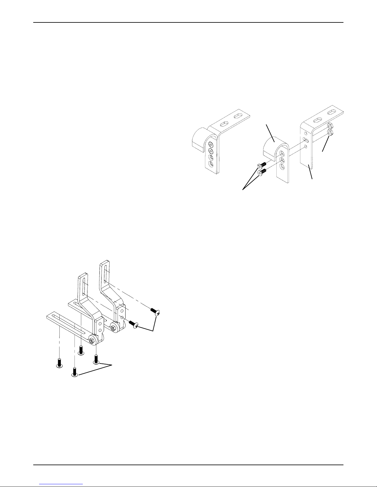
NOTE: Make sure the growth bracket is positioned correctly . The flat portion of the growth bracket provides depth
adjustment for the Ulti-Mate Base. The angled portion of
the growth bracket provides height adjustment for the
Curved Back. See FIGURE 1.
3. Install four (4) of the mounting screws through the
holes in the growth bracket and into the back shell.
Securely tighten.
1

NOTE: On the back, the standard attachment points are
the top and bottom sets of holes. Refer to the A TTACH-
MENT POINTS chart in this instruction sheet for optional
attachment points.
4. Install four (4) of the mounting screws through the
holes in the growth bracket and into the underside of
the Ulti-Mate Base. Securely tighten.
NOTE: On the seat, the standard attachment points are
the front and back sets of holes. Refer to the ATT ACH-
MENT POINTS chart in this instruction sheet for optional
attachment points.
5. If adjustment is required, refer to ADJUSTING THE
GROWTH BRACKET in this instruction sheet. Otherwise, continue on with A TTACHING/ADJUSTING
THE LA TERAL SUPPORTS in this instruction sheet.
ADJUSTING THE ULTI-MATE BASE
DEPTH.
1. Remove the four (4) mounting screws that secure
the growth bracket to the Ulti-Mate Base.
2. Adjust the seat forward or back until the desired
mounting position is obtained.
3. Reinstall the four (4) mounting screws through the
growth bracket and into the seat. Securely tighten.
chart
Refer to the ATTACHMENT POINTS
instruction sheet for standard and optional attachment points.
in this
ATTACHING / ADJUSTING THE
ADJUSTABLE ANGLE GROWTH
BRACKET (FIGURE 2)
Curved
Back
Center Panel
Top Set
Bottom Set
Ulti-Mate
Base
Adjustment
Holes
NOTE: Your Growth Bracket may have SLOTS instead of Adjustment Holes.
FIGURE 1 - FIGURE 1 -
FIGURE 1 -
FIGURE 1 - FIGURE 1 -
GRGR
GR
GRGR
AA
A
AA
OO
WTH BRAWTH BRA
O
WTH BRA
OO
WTH BRAWTH BRA
T TT T
AA
CHING/ADJUSTING CHING/ADJUSTING
T T
A
CHING/ADJUSTING
T TT T
AA
CHING/ADJUSTING CHING/ADJUSTING
CKETCKET
-CHILD/JUNIOR SIZES-CHILD/JUNIOR SIZES
CKET
-CHILD/JUNIOR SIZES
CKETCKET
-CHILD/JUNIOR SIZES-CHILD/JUNIOR SIZES
Six (6) T-nutted
Mounting Holes
Mounting
Screws
Growth Bracket
THE FIXEDTHE FIXED
THE FIXED
THE FIXEDTHE FIXED
Adjusting the Growth Bracket (FIGURE 1)
NOTE:The growth bracket provides up to a 3-inch depth
adjustment and up to a 3-inch height adjustment.
ADJUSTING THE BACK HEIGHT.
1. If necessary, unzip center panel of the back cover.
2. Remove the four (4) mounting screws that secure
the growth bracket to the back.
3. Adjust the back up or down until the desired mounting position is obtained.
4. Reinstall the four (4) mounting screws through the
growth bracket and into the back shell. Securely
tighten. Refer to the ATTACHMENT POINTS
in this instruction sheet for standard and optional
attachment points.
5. If all attachments and adjustments are complete, zip
center panel of back cover closed.
chart
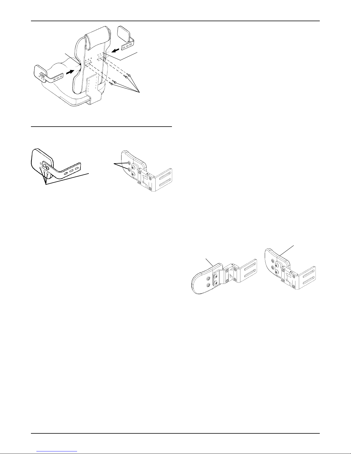
ATTACHING THE ADJUSTABLE ANGLE
GROWTH BRACKET
NOTE: The growth bracket attaches to the child/junior
sized curved back ONLY.
1. Remove the adjustable angle growth bracket and
attaching hardware from the packaging.
2. Unzip the center panel of the back cover, exposing
the six (6) T-nutted mounting holes.
NOTE: Make sure that the growth bracket is positioned
correctly . The flat portion of the adjustable angle bracket
growth bracket provides depth adjustment for the Ultimate base. The angled portion of the adjustable angle
bracket height adjustment for the curved back
(FIGURE 1).
3. Install four (4) of the mounting screws through the
slots in the adjustable angle growth bracket and into
the underside of the Ulti-mate base. Securely tighten.
NOTE: On the Ulti-mate base, the standard attachment
points are the front and rear four (4) holes. Refer to the
ATTACHMENT POINTS
optional attachment points.
4. Install two (2) of the mounting screws through the
slots on the adjustable angle growth bracket and
into the back shell. Securely tighten.
NOTE: On the curved back, the standard attachment
points are the MIDDLE set of holes. Refer to the
ATTACHMENT POINTS
optional attachment points.
5. If adjustment is required, refer to ADJUSTING THE
GROWTH BRACKET in this instruction sheet.
in this instruction sheet for
in this instruction sheet for
ADJUSTING THE GROWTH BRACKET
ADJUSTING THE BACK HEIGHT.
1. If necessary, unzip center panel of the back cover.
2
2. Loosen the two (2) mounting screws that secure the
growth bracket to the back.
1. Remove the two (2) attaching screws and nuts on
the adjustable angle back hooks.
3. Adjust the back up or down until the desired mounting position is obtained.
4. Securely tighten the two (2) mounting screws.
5. If more adjustment is needed, the adjustment screws
can be completely removed, and the bracket set to
a NEW T-nutted hole location. Refer to the
A TTACHMENT POINTS
optional attachment points.
6. Zip center panel of back cover closed.
in this instruction sheet for
ADJUSTING THE ULTI-MATE BASE DEPTH.
1. If necessary, unzip center panel of the back cover.
2. Loosen the four (4) mounting screws that secure the
growth bracket to the Ulti-Mate Base.
3. Adjust the seat forward or back until the desired
mounting position is obtained.
4. Securely tighten the two (2) mounting screws.
5. If more adjustment is needed, the adjustment screws
can be completely removed, and the bracket set to
a NEW T-nutted hole location. Refer to the
A TTACHMENT POINTS
optional attachment points.
6. Zip center panel of back cover closed.
in this instruction sheet for
2. Recline the back to the desired angle.
3. Align one (1) round hole and one (1) slotted hole on
the back L-bracket with two (2) of the holes on the
hook portion.
4. Reinstall the two (2) screws and nuts and securely
tighten.
Hook Portion
Nuts
L-Bracket
Attaching Screws
FIGURE 3 - FIGURE 3 -
FIGURE 3 -
FIGURE 3 - FIGURE 3 -
ADJUSTING ADJUSTING
ADJUSTING
ADJUSTING ADJUSTING
THE THE
ANGLE OF ANGLE OF
THE
ANGLE OF
THE THE
ANGLE OF ANGLE OF
THE BTHE B
THE B
THE BTHE B
AA
A
AA
CKCK
CK
CKCK
ATTACHING/ADJUSTING THE
LATERAL SUPPORTS (FIGURE 4)
Attaching
1. Remove lateral support and mounting hardware from
packaging.
Top Mounting
Screws
Bottom Mounting
Screws
FIGURE 2 - FIGURE 2 -
FIGURE 2 -
FIGURE 2 - FIGURE 2 -
ADJUSTADJUST
ADJUST
ADJUSTADJUST
AA
A
AA
ABLE ABLE
ABLE
ABLE ABLE
TTTT
AA
CHING / CHING /
TT
A
CHING /
TTTT
AA
CHING / CHING /
ANGLE GRANGLE GR
ANGLE GR
ANGLE GRANGLE GR
ADJUSTING ADJUSTING
ADJUSTING
ADJUSTING ADJUSTING
OO
WTH BRAWTH BRA
O
WTH BRA
OO
WTH BRAWTH BRA
THETHE
THE
THETHE
CKETCKET
CKET
CKETCKET
ADJUSTING THE ANGLE OF THE BACK
(FIGURE 3)
NOTE: The adjustable angle growth bracket is infinitely
angle adjustable. The back-to-seat angle is set by the
location of the mounting points for the back in relation to
the base and by changing the hole positions of the adjustable angle back hooks.
2. Feed lateral support bracket through the slots provided in the back cover.
3. Attach lateral support bracket to back shell as shown
in FIGURE 2 with the two (2) mounting screws pro-
vided. Repeat for opposite side.
4. If adjustment is required, refer to ADJUSTING THE
LATERAL SUPPORTS in this instruction sheet. If
so equipped continue with USING THE SWING-
AW A Y LATERAL SUPPORTS.
Adjusting
NOTE: Lateral supports provide adjustment up to 2inches for height; 2-inches for width, and 1-inch for depth.
STANDARD ADJUSTMENTS.
NOTE: There are additional mounting holes located on
the back shell to provide width and height adjustment for
a more comfortable fit. Only the child/junior size is shown
for clarity . Refer to the ATTACHMENT POINTS chart in
this instruction sheet for standard and optional attachment points.
3
Slot
Standard
Adjustment
T-nutted
Mounting
Holes
3. For height adjustment on adult sizes, remove the
two (2) mounting screws.
4. Raise or lower the lateral support and align the slots
with the back holes in the desired mounting positions.
5. Reinsert the two (2) mounting screws and securely
retighten.
6. Zip center panel of back cover closed.
Mounting
Screws
NOTE: Your Growth Bracket may have SLOTS instead of Adjustment Holes.
FIXED LAFIXED LA
FIXED LA
FIXED LAFIXED LA
SUPPORSUPPOR
SUPPOR
SUPPORSUPPOR
FIGURE 4 - FIGURE 4 -
FIGURE 4 -
FIGURE 4 - FIGURE 4 -
1. If necessary, unzip the center panel of back cover.
2. For minimal width adjustment, loosen the mounting
screws and slide support bracket in or out and retighten mounting screws.
3. For further width and/or height adjustment, remove
the two (2) mounting screws.
TERALTERAL
TERAL
TERALTERAL
TT
T
TT
AA
A
AA
THE LATHE LA
THE LA
THE LATHE LA
SWINGASWINGA
SWINGA
SWINGASWINGA
Optional
Adjustment
Holes
TTTT
AA
CHING/ADJUSTINGCHING/ADJUSTING
TT
A
CHING/ADJUSTING
TTTT
AA
CHING/ADJUSTINGCHING/ADJUSTING
TERAL SUPPORTERAL SUPPOR
TERAL SUPPOR
TERAL SUPPORTERAL SUPPOR
WW
AA
W
A
WW
AA
SUPPORSUPPOR
SUPPOR
SUPPORSUPPOR
TSTS
TS
TSTS
Y LAY LA
Y LA
Y LAY LA
TERALTERAL
TERAL
TERALTERAL
TT
T
TT
Pad Adjustment
1. Unzip the hideaway cover and pull the cover partially off the pad to expose the mounting screws.
2. Remove the two (2) pad mounting screws.
3. Reposition the pad depth to the desired position.
4. Reinsert the two (2) mounting screws and securely
tighten.
5. Zip the hideaway cover over the pad.
USING THE SWINGAWAY
LATERAL SUPPORTS (FIGURE 5)
NOTE: The swingaway lateral supports were designed
for ease in removing the individual from the KSS seating
system.
1. Lift up on the lateral support and push outward, away
from the wheelchair.
2. T o lock lateral support in place, pull back inward until
lateral support snaps in place.
Locked
Position
Unlocked
Position
4. Place the lateral support in the desired mounting
position.
5. Reinsert the two (2) mounting screws. Securely
tighten.
6. If all attachments and adjustments are complete, zip
center panel of back cover closed.
OPTIONAL ADJUSTMENT (FIGURE 4).
1. Fixed lateral supports have height and depth ad-
justment holes on the outside of the padded portion
of the lateral support. Follow STEPS 3-5 in STAN-
DARD ADJUSTMENTS in this section of the instruction sheet. Repeat for opposite lateral support.
SWINGAWAY LATERAL SUPPORTS
Bracket Adjustment
1. Unzip center panel of back cover.
2. For width adjustment, loosen the mounting screws
and slide the support bracket in or out and retighten
the mounting screws.
FIGURE 5 - USING FIGURE 5 - USING
FIGURE 5 - USING
FIGURE 5 - USING FIGURE 5 - USING
LALA
TERAL SUPPORTERAL SUPPOR
LA
TERAL SUPPOR
LALA
TERAL SUPPORTERAL SUPPOR
THE SWINGATHE SWINGA
THE SWINGA
THE SWINGATHE SWINGA
TSTS
TS
TSTS
WW
AA
YY
W
A
Y
WW
AA
YY
ATTACHING/ADJUSTING THE
MOUNTING HOOKS (FIGURE 6)
Attaching the Mounting Hooks
CHILD/JUNIOR SIZES.
1. Remove four (4) mounting hooks from packaging.
2. Slide one (1) hook through the slot provided in the
back cover. Attach to the upper corner , on either side
of the back, with two (2) of the mounting screws provided. Repeat for opposite side.
3. Attach one (1) mounting hook to the front corner , on
either side of the seat, with two (2) of the mounting
screws provided. Repeat for opposite side.
4
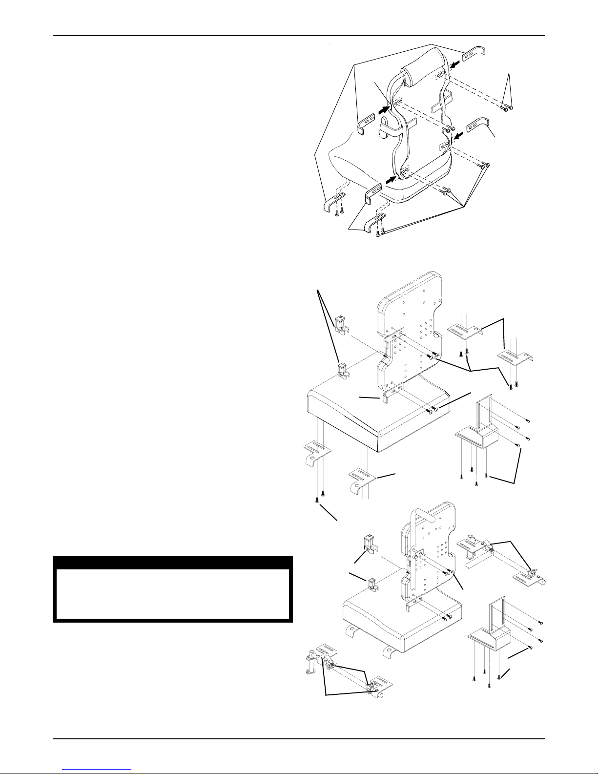
ADULT SIZES.
1. Remove eight (8) mounting hooks from the packaging.
2. Slide one (1) hook through the slot provided in the
back cover. Attach to the upper corner , on either side
of the back, with two (2) of the mounting screws provided. Repeat for opposite side.
3. Slide one (1) hook through the slot provided in the
back cover. Attach to the lower corner , on either side
of the back, with two (2) of the mounting screws provided. Repeat for procedure for opposite side.
4. Attach one (1) mounting hook to the front corner , on
either side of the seat, with two (2) of the mounting
screws provided. Repeat for opposite side.
5. Attach one (1) mounting hook to the back corner , on
either side of the seat, with two (2) of the mounting
screws provided. Repeat for opposite side.
Adjusting the Mounting Hooks
NOTE: Refer to the ATTACHMENT POINTS chart in
this instruction sheet for adjustment locations.
1. If necessary, unzip the back cover.
2. CHILD/JUNIOR AND ADULT SIZES - For minimal
width adjustment, loosen the mounting screws and
adjust the hooks in or out and retighten the mounting screws.
3. ADULT SIZE ONL Y - If further adjustment is needed:
a. Remove the mounting screws that secure the
mounting hooks to the back/seat.
b. Adjust the mounting hooks to desired mounting
position.
c. Reinsert the mounting screws. Securely tighten.
4. TRANSPORT OPTION - For seat adjustment, loosen
the mounting screws and adjust the hooks back and
forth.
NOTE: Some configurations for seat depth changes may
require REVERSING seat mounting hooks.
For back adjustment, loosen the mounting screws
and adjust the hooks side-to-side. Retighten the
mounting screws.
Mounting Hooks
Slot
* Mounting
Hooks
* These items are only
needed on the adult size.
Mounting
Screws
* Mounting
Hook
* Mounting
Screws
TRANSPORT READY OPTION (TRRO)
Twist Release
Clamp
Four (4) Mounting
Hooks
Seat
Mounting
Hooks
Mounting
Screws
Seat Mounting
Hooks
Mounting
Screws
Mounting
Screws
Quick Release
Clamps
WARNING
Ensure the seating system mounting brackets are
correctly positioned and clamps are securely
engaged. Failure to do so may result in serious
bodily injury.
5. If all attachments and adjustments are complete, zip
the back cover closed.
n
NOTE: For 12 and 14-inch seat depth ALL four
(4) mounting holes will be used.
n
NOTE: For 16-inch seat depth the FRONT two
(2) mounting holes will be used.
Twist Release
Clamp
n
See NOTES
FIGURE 6 - FIGURE 6 -
FIGURE 6 -
FIGURE 6 - FIGURE 6 -
5
Quick Release Clamps
AA
TTTT
AA
CHING/ADJUSTING CHING/ADJUSTING
A
TT
A
CHING/ADJUSTING
AA
TTTT
AA
CHING/ADJUSTING CHING/ADJUSTING
MOUNTING HOOKSMOUNTING HOOKS
MOUNTING HOOKS
MOUNTING HOOKSMOUNTING HOOKS
Mounting
Screws
Mounting
Screws
THETHE
THE
THETHE
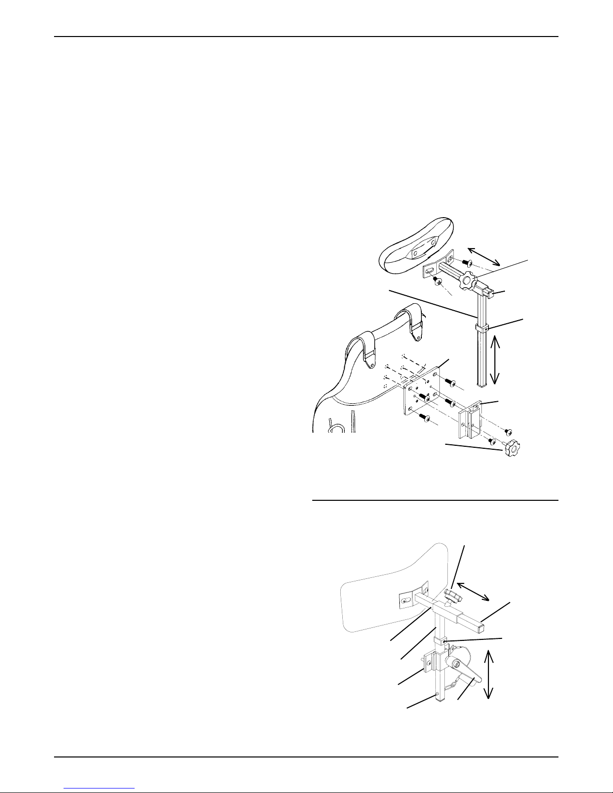
ATTACHING/ADJUSTING THE
NECK SUPPORT (FIGURE 7)
Attaching the Neck Support
CURVED BACK.
1. Remove neck support bracket from packaging.
2. Unzip back cover on both sides of center panel.
3. Lift center panel.
NOTE: If a NEW neck support is used on an EXISTING
Curved Back than the adapter plate and support bracket
MUST be used.
NOTE: If a NEW neck support is used on a NEW Curved
Back than the support bracket can be used WITHOUT
the adapter plate.
4. Perform Steps 4a. and 4b. or 4c.:
a. Secure neck adapter plate to the back shell
with the four (4) mounting screws provided (If
applicable).
b. Then secure the neck support bracket to the
neck adapter plate using the two (2) mounting
screws provided.
c. Secure the vertical neck post to the back shell
using the two (2) mounting screws provided.
5. Close center panel with the vertical neck post exposed through the slot provided in upholstery.
6. Zip the back cover closed.
7. Insert horizontal post into vertical post and secure
with thumbscrew knob.
8. Insert vertical post into neck support bracket.
9. Secure with a thumbscrew knob or adjustable lever.
10. Insert detent pin into through both walls of vertical
post (Transport Ready Option [TRRO]).
11. If adjustment is required, refer to ADJUSTING THE
NECK SUPPORT in this instruction sheet.
ULTI-MATE AIR BACK.
NOTE: The standard attachment points are where the
eyelets are located in the upholstery.
1. If there are no eyelets, pierce a hole pattern in the
fabric, that resembles the pattern found on the neck
support bracket. Ensure the pattern is aligned with
the T-nutted holes found on the back shell.
NOTE: The cover may need to be removed to get a
more precise location of the T-nutted holes before piercing the hole pattern in the fabric.
NOTE: There is an extra set of T-nutted holes found on the
back shell for optional height adjustment. T o make these holes
accessible, pierce a hole in the fabric aligned with the T-nutted hole in the back shell. Repeat for opposite hole.
NOTE: If a NEW neck support is used on an EXISTING
Curved Back than the adapter plate and support bracket
MUST be used.
NOTE: If a NEW neck support is used on a NEW Curved
Back than the support bracket can be used WITHOUT
the adapter plate.
2. Secure neck adapter plate to the back shell with the
four (4) long mounting screws provided.
3. Attach neck support bracket to the adapter plate using
the two (2) short mounting screws provided.
4. Insert horizontal post into vertical post and secure
with thumbscrew.
5. If adjustment is required, refer to ADJUSTING
THE NECK SUPPORT in this instruction sheet.
Depth
Adjustment
Vertical Post
Neck
Adapter
Plate
Neck Support
Thumbscrew Knob
NOTE: Only the curved back is shown for clarity. The
neck support on the Ulti-mate Air Back adjusts in the
same manner.
NOTE: Ensure that the retaining screw is located
in the end of the horizontal post.
Thumbscrew Knob
Depth
Adjustment
Horizontal Post
Vertical Post
Neck Support
Bracket
Detent Pin
NOTE: Neck Adapter Plate NOT shown.
FIGURE 7 - FIGURE 7 -
FIGURE 7 -
FIGURE 7 - FIGURE 7 -
ADJUSTING ADJUSTING
ADJUSTING
ADJUSTING ADJUSTING
Adjustment Lever
THE NECK SUPPORTHE NECK SUPPOR
THE NECK SUPPOR
THE NECK SUPPORTHE NECK SUPPOR
Thumb-
screw
Knob
Horizontal
Post
Height
Adjustment
Stop
Height
Adjustment
Bracket
Retaining
Screw
Height
Adjustment
Stop
Height
Adjustment
TT
T
TT
6

ADJUSTING THE NECK SUPPORT
Curved Back and Ulti-Mate Air Back
1. Height Adjustment - Loosen the thumbscrew knob
or adjustment lever on the neck support bracket.
Loosen the height adjustment stop setscrew. Adjust
the neck support to the desired height and retighten
the thumbscrew knob or adjustment lever. Slide
height adjustment stop to the top of the support
bracket and retighten setscrew.
Insert detent pin into through both walls of vertical post (Transport Ready Option [TRRO]).
NOTE: The height adjustment stop allows the neck support to be removed for transfers, then reinstalled back to
the exact height set by the location of the height adjustment stop.
2. Depth Adjustment - Loosen the thumbscrew knob
on the horizontal post, adjust the neck support to the
desired depth and retighten the thumbscrew knob.
NOTE: On the Ulti-Mate Air Back further adjustment can
be obtained by utilizing the extra set of T-nutted holes in
the back shell. Refer to A TT ACHING THE NECK SUP-
PORT in this instruction sheet.
ATTACHING/ADJUSTING THE
HEIGHT/REVERSING THE
PAD/USING THE FLIP DOWN
ABDUCTOR (FIGURE 8)
Reversing the Cushion of the Flip
Down Abductor (FIGURE 8-DETAIL "B")
1. To unlock and flip down abductor, press release
button (FIGURE 8-DETAIL "C").
2. Using a socket key, remove the adjustment
screw and washer on the vertical portion of the
mounting bracket.
3. Completely remove the top tube from the telescoping tube assembly.
4. Rotate top portion 180
5. Reinstall top tube portion.
6. Follow STEPS 4-5 in ADJUSTING THE FLIP
DOWN ABDUCTOR.
DETDET
AIL "A"AIL "A"
DET
AIL "A"
DETDET
AIL "A"AIL "A"
Flip-Down
Abductor
Flip-Down
Abductor
DETDET
AIL "B"AIL "B"
DET
AIL "B"
DETDET
AIL "B"AIL "B"
Flip-Down
Abductor
Bracket
o.
Seat
Mounting
Screws
Attaching the Flip Down Abductor (FIGURE
8-DETAIL "A")
NOTE: Refer to the ATTACHMENT POINTS chart in
this instruction sheet for attachment location.
1. Remove the flip down abductor and attaching hardware from packaging.
2. Attach the flip down abductor bracket to the underside
of the seat with the four (4) mounting screws provided.
3. To remove the flip down abductor reverse STEP 2.
Adjusting the Height of the Flip Down
Abductor (FIGURE 8-DETAIL "B")
1. To unlock and flip down abductor, press release button (FIGURE 8-DET AIL "C").
2. Using a socket key , loosen the adjustment screw on
the vertical portion of the mounting bracket.
3. Adjust the flip down abductor to the desired height.
4. Securely tighten the adjustment screw and then
check pad height.
5. Repeat Steps 1 through 4 until proper height is
obtained.
Mounting
Screws
Telescoping
Tube Assembly
DETDET
AIL "C"AIL "C"
DET
AIL "C"
DETDET
AIL "C"AIL "C"
FIGURE 8 - FIGURE 8 -
FIGURE 8 -
FIGURE 8 - FIGURE 8 -
HEIGHT/REVERSING HEIGHT/REVERSING
HEIGHT/REVERSING
HEIGHT/REVERSING HEIGHT/REVERSING
USING USING
USING
USING USING
AA
A
AA
THE FLIP DOTHE FLIP DO
THE FLIP DO
THE FLIP DOTHE FLIP DO
Flip-Down
Abductor
Bracket
Release
Button
TTTT
AA
CHING/ADJUSTING CHING/ADJUSTING
TT
A
CHING/ADJUSTING
TTTT
AA
CHING/ADJUSTING CHING/ADJUSTING
Adjusting Screw
Locked
Position
Unlocked
Position
THE CUSHION/THE CUSHION/
THE CUSHION/
THE CUSHION/THE CUSHION/
WN WN
WN
WN WN
ABDUCTABDUCT
ABDUCT
ABDUCTABDUCT
OROR
OR
OROR
THETHE
THE
THETHE
Using the Flip-Down Abductor
(FIGURE 8-DETAIL "C")
1. To unlock and flip down press release button.
2. To lock in place pull up on abductor until an audible click is heard.
7

ATTACHING/USING THE LAP
BELT (FIGURES 9 AND 10)
Attaching the Lap Belt
WARNING
It is strongly recommended that the lap belt
be strapped across the hip area with an
angle of 45o to the seating surface. Angles
less than 45o make it easier for the user to slip
under the belt if it is improperly tightened.
1. The lap belt can be anchored in one (1) of the
two (2) possible locations:
a. In one (1) of the T-nutted holes located on
the underside of the seat.
b. In one (1) of the holes in the side frame of
the wheelchair.
NOTE: DO NOT reposition the lap belt mounting
location from the factory installation on the TRANSPORT READY OPTION (TRRO).
NOTE: The most desirable location for the mounting screws will be determined by the size of the
client involved and the angle achieved by trying the
various attachment points with the client seated
comfortably in the wheelchair.
SEASEA
T T
ATTATT
AA
FRAME FRAME
FRAME
FRAME FRAME
ATTATT
ATT
ATTATT
AA
CHMENTCHMENT
A
CHMENT
AA
CHMENTCHMENT
SEA
SEASEA
T
T T
ATT
ATTATT
CHMENTCHMENT
A
CHMENT
AA
CHMENTCHMENT
2. Determine the most suitable attachment point. Put
the padded side of the belt toward the seating
surface.
3. Align the hole located at the anchor end of the
belt with the chosen attachment point and insert
one (1) of the mounting screws provided. HAND
TIGHTEN ONLY. Repeat for opposite side.
Using the Lap Belt
WARNING
Ensure that the seat is fixed to the wheelchair .
A loose seat may lead to potentially dangerous situations with positioning devices.
It is strongly recommended that the lap belt
be strapped across the hip area with an
angle of 45
less than 45o make it easier for the user to slip
under the belt if it is improperly tightened.
NOTE: Stabilize from the ground up. A stable base
(seat) and footrest are the first steps to a stable
pelvis. Also, the user should be lightly clothed for
the initial adjustment.
NOTE: A belt angle of 45
best stability and positioning. The belt will apply its
pressure directly to the hips, usually allowing more
force to be applied without discomfort.
o
to the seating surface. Angles
o
will usually provide the
Mounting
Screws
Lap Belt
Wheelchair
Frame
Lap Belt (Acceptable lap belt angle is 45o)
B
a
c
k
Seat
45
o
B
a
c
k
Seat
Mounting Screws
B
a
c
k
Seat
Lap
Belt
1. Adjust the slide, located at each end of the belt,
to fit the client with proper tension.
2. The plastic D-rings, located at the front of the belt,
can be pulled or released to conveniently tighten
the belt to provide extra tension if needed or
loosen the belt to allow for bulky clothing, etc.
NOTE: When all final adjustments have been made
and the client is comfortable with the fit of the lap
belt, any excess lengths of material can be cut off,
keeping in mind the potential future growth of the
client. The cut end can be melted slightly to prevent fraying.
NOTE: Only the Child/Junior lap belt is shown for clarity .
Anchor
End
Padded
Portion
D-Rings
Buckle
Slider
FIGURE 9 - FIGURE 9 -
FIGURE 9 -
FIGURE 9 - FIGURE 9 -
AA
TTTT
A
TT
AA
TTTT
AA
CHING CHING
A
CHING
AA
CHING CHING
THE LAP BELTHE LAP BEL
THE LAP BEL
THE LAP BELTHE LAP BEL
FIGURE 10 - USING FIGURE 10 - USING
FIGURE 10 - USING
TT
T
TT
FIGURE 10 - USING FIGURE 10 - USING
THE LAP BELTHE LAP BEL
THE LAP BEL
THE LAP BELTHE LAP BEL
TT
T
TT
8

POSITIONING/ADJUSTING THE KSS
SEATING SYSTEM IN THE
WHEELCHAIR
HARDWARE REFERENCE CHART
NOTE: This chart is a general guideline for recommended mounting hardware.
With the individual positioned in the KSS seating system:
1. Check that the width and height of the system is
fitted properly to the individual using the system. If
adjustment is needed, refer to ADJUSTING THE
GROWTH BRACKET in this instruction sheet.
2. Check to make sure the neck support is properly
positioned, with the correct height and depth, for the
individual using the system. If adjustment is needed,
refer to ADJUSTING THE NECK SUPPORT in this
instruction sheet.
3. Check to make sure the lateral supports are properly positioned, with the correct width and height, for
the individual using the system. If adjustment is
needed, refer to ADJUSTING THE LA TERAL SUP-
PORTS in this instruction sheet.
4. Check to make sure the flip-down abductor is securely tightened.
5. Check to make sure the lap belt is securely fastened.
Is the lap belt uncomfortably compressing the abdomen when properly tightened? You can mount the
anchor points further forward to increase the belt
angle. If adjustment is necessary , refer to A TT ACH-
ING/USING THE LAP BEL T in this instruction sheet.
SECURING THE KSS SEATING SYSTEM
TO THE WHEELCHAIR FRAME
The following recommendations are made for the safe
installation and use of mounting hardware on seating
systems:
SAFETY SUMMARY
GENERAL W ARNING
Hardware Clamps
With With Out
Growth Bracket Growth Bracket
BACK Twist Release Twist Release
(SEE FIGURE 11) Fixed Release
(SEE FIGURE 13)
SEAT Quick Release Quick Release
(SEE FIGURE 12) Fixed Release
(SEE FIGURE 14)
PROCEDURE 1 - INSTALLING
CLAMPS ON SEATING SYSTEMS
WITH A GROWTH BRACKET
Twist Release Clamps For Back (FIGURE 11)
NOTE: Refer to INSTALLATION WARNING in the
SAFETY SUMMARY before proceeding.
1. Make sure that the back mounting hooks are flush
against the back canes.
2. Loosen the socket screw that opens the twist release clamp.
NOTE: There is a right and left twist release clamp.
Make sure when installing that the socket screw
adjustment is on the outside of the wheelchair
frame.
NOTE: FOR TRANSPORT READY OPTION (TRRO) There is a right and left twist release clamp. Make sure
when installing that the socket screw adjustment is on
the INSIDE of the wheelchair frame.
3. Install the open end of the twist release clamp below
the back mounting hook so that the locking mechanism rests on top of the back mounting hook.
Ensure that the seat and back of the seating system are fixed to the wheelchair. A loose seat or
back may lead to potentially dangerous situations with positioning devices.
Ensure that ALL hardware is tight at ALL times.
INST ALLATION WARNING
DO NOT install twist, quick, and fixed release
clamps in any other locations than specified in
this instruction sheet - otherwise, the seating system will not be secured properly to the wheelchair and bodily injury may occur.
4. Loosely tighten the socket screw.
5. Repeat STEPS 1- 4 for the other side.
6. Make sure both twist release clamps are flush
against the back mounting hooks and that the locking mechanism rests on top of the back mounting
hooks.
7. Torque socket screw to 75 - inch pounds.
9

Locking Mechanism
7. Once quick release mounting clamps are secured,
do one (1) of following:
Twist Release
Cane Clamp
Socket Screw
Inside
Back Cane
Seat Rail
NOTE: For TRANSPORT READY OPTION (TRRO)
Twist Release Cane Clamp is REVERSED.
FIGURE 11- FIGURE 11-
FIGURE 11-
FIGURE 11- FIGURE 11-
8. Once twist release mounting clamps are secured, do
one (1) of following:
A. Refer to QUICK RELEASE CLAMPS FOR
B. Refer to USING CLAMPS in this instruction
TWIST RELEASE CLAMPS FOR BTWIST RELEASE CLAMPS FOR B
TWIST RELEASE CLAMPS FOR B
TWIST RELEASE CLAMPS FOR BTWIST RELEASE CLAMPS FOR B
SEAT in PROCEDURE 1 of this instruction sheet.
sheet.
Back Mounting
Hook
AA
CKCK
A
CK
AA
CKCK
Quick Release Clamps For Seat
(FIGURE 12)
A. Refer to TWIST RELEASE CLAMPS FOR
BACK in PROCEDURE 1 of this instruction
sheet.
B. Refer to USING CLAMPS in this instruction
sheet.
DETDET
AIL AIL
DET
Insert
Lock Washer
Sleeve
Back Cane
Fixed
Portion
Mounting Hook
FIGURE 12- QUICK RELEASE CLAMPS FOR SEAFIGURE 12- QUICK RELEASE CLAMPS FOR SEA
FIGURE 12- QUICK RELEASE CLAMPS FOR SEA
FIGURE 12- QUICK RELEASE CLAMPS FOR SEAFIGURE 12- QUICK RELEASE CLAMPS FOR SEA
Quick Release
Rail Clamp
DETDET
““
AIL
“
AIL AIL
““
Internal
Mounting
Screw
Release
Portion
PROCEDURE 2 - INSTALLING
CLAMPS ON SEATING SYSTEMS
WITHOUT A GROWTH BRACKET
A”A”
A”
A”A”
TT
T
TT
NOTE: Refer to INSTALLATION WARNING in the
SAFETY SUMMARY before proceeding.
NOTE: The quick release clamps are designed to fit
either 1-inch rail tubing or, with insert provided, 7/8-inch
rail tubing.
1. Remove the sleeve, lock washer, and internal
threaded mounting screw from the quick release
clamp (DET AIL “A”).
2. Place the quick release clamp on the seat rail.
3. If quick release clamp is not tightly fitted around seat
rail tubing, install insert provided as shown in DE-
T AIL “A”.
4. Install the quick release clamp onto the seat rail so
that the fixed portion is flush against and rests on top
of the mounting hook and the release portion is between the front riggings and the mounting hook.
5. Reinstall the sleeve, lock washer , and internal mounting screw into the quick release rail clamp and torque
to 75 - inch pounds.
6. Repeat STEPS 1- 5 for other side.
Twist Release Clamps For Back
(FIGURE 11)
NOTE: Refer to INSTALLATION WARNING in the
SAFETY SUMMARY before proceeding.
1. Make sure that the back mounting hooks are flush
against the back canes.
2. Loosen the socket screw that opens the twist release clamp.
NOTE: There is a right and left twist release clamp. Make
sure when installing that the socket screw adjustment is
on the outside of the wheelchair frame.
3. Install the open end of the twist release clamp below
the back mounting hook so that the locking mechanism rests on top of the mounting hook.
4. Loosely tighten the socket screw.
5. Repeat STEPS 1- 4 for the other side.
6. Make sure both twist release clamps are flush against
the back mounting hooks and that the locking mechanism rests on top of the back mounting hooks.
10

7. Torque socket screw to 75 - inch pounds.
8. Once twist release mounting clamps are secured,
do one (1) of following:
A. Refer to FIXED RELEASE CLAMPS FOR
BACK in PROCEDURE 2 of this instruction
sheet.
B. Refer to USING CLAMPS in this instruction
sheet.
DETDET
AIL AIL
DET
AIL
DETDET
AIL AIL
Mounting
Hook
Back Cane
“B”“B”
“B”
“B”“B”
Sleeve
Lock
Washer
Fixed
Portion
Internal Mounting
Screw
Fixed Release Clamps For Back (FIGURE 13)
NOTE: Refer to INSTALLATION WARNING in the
SAFETY SUMMARY before proceeding.
NOTE: The fixed release rail/cane clamps are designed
to fit either 1-inch rail tubing or, with insert provided, 7/8inch rail tubing.
1. Remove the mounting screw, lock washer, and
internal threaded mounting screw from the fixed
release clamps (DET AIL “B”).
2. Place the fixed release clamp on the back cane.
3. If fixed release clamp is not tightly fitted around back
cane tubing, install insert provided as shown in DE-
T AIL “A”.
4. Install the fixed release clamp onto the back rail so
that the fixed portion is flush against and rests on top
of the mounting hook and is located between the
seat rail and the bottom of the mounting hook.
5. Reinstall the mounting screw, lock washer, and
internal mounting screw into the fixed release rail/
cane clamp and torque to 75 - inch pounds.
6. Repeat STEPS 1 - 5 for other side.
7. Once fixed release mounting clamps are secured,
do one (1) of following:
A. Refer to QUICK RELEASE CLAMPS FOR
SEAT in PROCEDURE 2 of this instruction sheet.
B. Refer to USING CLAMPS in this instruction sheet.
Twist Release
Mounting
Hooks
Clamp
Inside of Back Cane
FIGURE 13- FIXED RELEASE CLAMPS FOR BFIGURE 13- FIXED RELEASE CLAMPS FOR B
FIGURE 13- FIXED RELEASE CLAMPS FOR B
FIGURE 13- FIXED RELEASE CLAMPS FOR BFIGURE 13- FIXED RELEASE CLAMPS FOR B
AA
A
AA
CKCK
CK
CKCK
Quick Release Clamps For Seat
(FIGURE 14)
NOTE: Refer to INSTALLATION WARNING in the
SAFETY SUMMARY before proceeding.
NOTE: The quick release and fixed release clamps are
designed to fit either 1-inch rail tubing or, with insert provided, 7/8-inch rail tubing.
1. Remove the sleeve, lock washer, and internal threaded
mounting screw from the quick release clamp (DE-
T AIL “C”).
2. Place the quick release clamp on the seat rail.
3. If quick release clamp is not tightly fitted around seat
rail tubing, install insert provided as shown in DE-
T AIL “C”.
4. Install the quick release clamp onto the seat rail so
that the fixed portion is flush against and rests on top
of the mounting hook and the release portion is between the front riggings and the mounting hook.
5. Reinstall the sleeve, lock washer, and internal mounting screw into the quick release clamp and torque to
75 - inch pounds.
6. Repeat STEPS 1- 5 for other side.
7. Once quick release mounting clamps are secured,
do one (1) of following:
A. Refer to FIXED RELEASE CLAMPS FOR
SEAT in PROCEDURE 2 of this instruction
sheet.
B. Refer to USING CLAMPS in this instruction
sheet.
Fixed Release
Clamp
Seat Rail
FIGURE 13- FIXED RELEASE CLAMPS FOR BFIGURE 13- FIXED RELEASE CLAMPS FOR B
FIGURE 13- FIXED RELEASE CLAMPS FOR B
FIGURE 13- FIXED RELEASE CLAMPS FOR BFIGURE 13- FIXED RELEASE CLAMPS FOR B
AA
A
AA
CKCK
CK
CKCK
11

Fixed Release Clamps For Seat
(FIGURE 14)
NOTE: Refer to INSTALLATION WARNING in the
SAFETY SUMMARY before proceeding.
NOTE: The quick release and fixed release clamps are
designed to fit either 1-inch rail tubing or, with insert provided, 7/8-inch rail tubing.
1. Remove the sleeve, lock washer, and internal
threaded mounting screw from the fixed release
clamp (DETAIL “C”).
USING CLAMPS
Twist Release (FIGURE 15)
1. To unlock the cane clamp, twist away from the
back cane.
2. To lock the cane clamp, twist in toward the back.
TT
OP OP
VIEWVIEW
T
OP
VIEW
TT
OP OP
VIEWVIEW
Twist Release
Cane Clamp
2. Place the fixed release clamp on the seat rail.
3. If fixed release clamp is not tightly fitted around seat rail
tubing, install insert provided as shown in DET AIL “C”.
4. Install the fixed release clamp onto the back rail so
that the fixed portion is flush against and rests on top
of the mounting hook and is located between the
seat rail and the bottom of the mounting hook.
5. Reinstall the sleeve, lock washer , and internal mounting screw into the fixed release clamp and torque to
75 - inch pounds.
6. Repeat STEPS 1-5 for other side.
7. Once fixed release mounting clamps are secured,
do one (1) of following:
A. Refer to QUICK RELEASE CLAMPS FOR
SEAT in PROCEDURE 2 of this instruction
sheet.
B. Refer to USING CLAMPS in this instruction sheet.
DETDET
AIL AIL
AIL
AIL AIL
“C”“C”
“C”
“C”“C”
Insert
Lock Washer
Sleeve
DET
DETDET
Internal Mounting Screw
Unlock
Mounting
Hook
Back Cane
NOTE: For TRANSPORT READY OPTION (TRRO)
Twist Release Cane Clamp is REVERSED.
FIGURE 15 - USING CLAMPS - FIGURE 15 - USING CLAMPS -
FIGURE 15 - USING CLAMPS -
FIGURE 15 - USING CLAMPS - FIGURE 15 - USING CLAMPS -
TWIST RELEASETWIST RELEASE
TWIST RELEASE
TWIST RELEASETWIST RELEASE
Back
Quick Release (FIGURE 16)
1. T o unlock, push down on the release tab of the quick
release rail clamps.
2. To lock, push down on the thumb-like feature of the
quick release rail clamps.
TO LOCK APPLY
PRESSURE HERE
TO UNLOCK APPLY
PRESSURE HERE
Back Cane
Fixed
Portion
Fixed Release
Clamp
NOTE: For TRANSPORT READY OPTION (TRRO) use
ONLY Quick Release Clamps on Seat Rails.
FIGURE 14 - QUICK RELEASE FIGURE 14 - QUICK RELEASE
FIGURE 14 - QUICK RELEASE
FIGURE 14 - QUICK RELEASE FIGURE 14 - QUICK RELEASE
RELEASE CLAMPS FOR SEARELEASE CLAMPS FOR SEA
RELEASE CLAMPS FOR SEA
RELEASE CLAMPS FOR SEARELEASE CLAMPS FOR SEA
Mounting
Hooks
Quick Release
Fixed
Portion
Clamp
AND FIXEDAND FIXED
AND FIXED
AND FIXEDAND FIXED
TT
T
TT
Release
Portion
Wheelchair
Frame
Quick Release
Rail Clamp
FIGURE 16 - USING CLAMPS - QUICK RELEASEFIGURE 16 - USING CLAMPS - QUICK RELEASE
FIGURE 16 - USING CLAMPS - QUICK RELEASE
FIGURE 16 - USING CLAMPS - QUICK RELEASEFIGURE 16 - USING CLAMPS - QUICK RELEASE
Mounting
Hook
12

ATTACHMENT POINTS FOR CURVED BACK
CHILD/JUNIOR SIZECHILD/JUNIOR SIZE
CHILD/JUNIOR SIZE
CHILD/JUNIOR SIZECHILD/JUNIOR SIZE
Top of Back
NN
N
NN
EE
E
EE
CC
C
CC
KK
K
KK
SS
S
SS
UU
U
UU
PP
P
PP
PP
P
PP
OO
O
OO
RR
R
RR
TT
T
TT
Bottom of Back
LL
L
LL
AA
A
AA
TT
T
TT
EE
E
EE
RR
R
RR
AA
A
AA
LL
L
LL
Top of Back
ADULADUL
T SIZET SIZE
ADUL
T SIZE
ADULADUL
T SIZET SIZE
Top of Back
Bottom of Back
Top of Back
SS
S
SS
UU
U
UU
PP
P
PP
PP
P
PP
OO
O
OO
RR
R
RR
TT
T
TT
GG
G
GG
RR
R
RR
OO
O
OO
WW
W
WW
TT
T
TT
HH
H
HH
Two (2) Mounting screws on each side.
BB
B
BB
RR
R
RR
AA
A
AA
CC
C
CC
KK
K
KK
EE
E
EE
TT
T
TT
Bottom of Back
Top of Back
Any combination.
Bottom of Back
Bottom of Back
The Adult Size does not require
a Growth Bracket. Extra mounting
hooks and mounting screws will be
supplied for the Curved Back and
Ulti-Mate Base
13

ATTACHMENT POINTS FOR CURVED BACK
(Continued)
CHILD/JUNIOR SIZECHILD/JUNIOR SIZE
CHILD/JUNIOR SIZE
CHILD/JUNIOR SIZECHILD/JUNIOR SIZE
ADULADUL
ADUL
ADULADUL
T SIZET SIZE
T SIZE
T SIZET SIZE
Top of Back
SS
S
SS
HH
H
HH
Optional
OO
O
OO
UU
U
UU
LL
L
LL
DD
D
DD
EE
E
EE
RR
R
RR
SS
S
SS
Optional
UU
U
UU
PP
P
PP
PP
P
PP
RR
R
RR
OO
O
OO
TT
T
TT
Standard location is the two (2) holes not
used by the growth bracket
Standard
Bottom of Back
Top of Back
MM
M
MM
OO
O
OO
UU
U
UU
NN
N
NN
TT
T
TT
II
I
II
NN
N
NN
GG
G
GG
Optional
Optional
Top of Back
OptionalStandard StandardOptional
Standard Standard
Top of Back
HH
H
HH
OO
O
OO
OO
O
OO
KK
K
KK
SS
S
SS
Bottom of Back
Bottom of Back
14

ATTACHMENT POINTS FOR ULTI-MATE BASE
CHILD/JUNIOR SIZECHILD/JUNIOR SIZE
CHILD/JUNIOR SIZE
CHILD/JUNIOR SIZECHILD/JUNIOR SIZE
GG
G
GG
RR
R
RR
OO
O
OO
WW
W
WW
TT
T
TT
HH
H
HH
Two (2) Mounting screws on each side.
BB
B
BB
RR
R
RR
AA
A
AA
CC
C
CC
KK
K
KK
EE
E
EE
TT
T
TT
LL
L
LL
AA
A
AA
PP
P
PP
Standard location is the two (2) holes
BB
B
BB
EE
E
EE
LL
L
LL
TT
T
TT
not used by the growth bracket)
Front of Seat
Any combination.
Rear of Seat
Front of Seat
ADULADUL
T SIZET SIZE
ADUL
T SIZE
ADULADUL
T SIZET SIZE
The Adult Size does not require
a Growth Bracket. Extra mounting
hooks and mounting screws will be
supplied for the Ulti-Mate Base
Front of Seat
Use either of the holes not being
use by the mounting hooks.
Rear of Seat
Lap Belt
(Optional)
Front of Seat
AA
A
AA
BB
B
BB
DD
D
DD
UU
U
UU
CC
C
CC
TT
T
TT
OO
O
OO
RR
R
RR
Rear of Seat
Rear of Seat
Front of Seat
Rear of Seat
15

ATTACHMENT POINTS FOR ULTI-MATE BASE
(Continued)
CHILD/JUNIOR SIZECHILD/JUNIOR SIZE
CHILD/JUNIOR SIZE
CHILD/JUNIOR SIZECHILD/JUNIOR SIZE
MM
M
MM
OO
O
OO
UU
U
UU
NN
N
NN
TT
T
TT
II
I
II
NN
N
NN
GG
G
GG
HH
H
HH
OO
O
OO
OO
O
OO
KK
K
KK
SS
S
SS
Front of Seat
Rear of Seat
ADULADUL
T SIZET SIZE
ADUL
T SIZE
ADULADUL
T SIZET SIZE
Front of Seat
Rear of Seat
16

FRONT VIEW BACK VIEW
Neck
Support
KSS SYSTEM FEATURES
Shoulder
Support
Mounting
Hook
Neck
Support
Curved
Back
Curved
Back
Mounting
Hook
Lateral
Support
Mounting
Support
Hook
Ulti-mate
Base
Lateral
Support
Ulti-mate Base
Lap Belt
(Transport Ready
Option [TRRO]
NOT shown.)
Abductor
CHILD/JUNIOR SIZE
Lateral
Support
Mounting
Hook
Lap Belt
FRONT VIEW BACK VIEW
Neck
Shoulder
Support
Curved
Back
Shoulder
Support
Growth Bracket
Neck
Support
Curved
Back
Mounting
Hook
Lateral
Support
Mounting
Hook
Ulti-mate
Base
Lateral
Support
Lap Belt (Transport
Ready Option [TRRO]
NOT shown.)
Abductor
Lateral
Support
Ulti-mate Base
Mounting
Hooks
ADULT SIZE
17
Mounting
Hooks
Shoulder
Support
Lap Belt

WASHING INSTRUCTIONS - COVERS
Outer Cover
1. Can be machine washed and dried.
2. DO NOT use bleach.
3. We DO NOT recommend machine washing or drying for colored NEOPRENE child cushion covers.
NOTE: We recommend cleaning the cover on a regular
basis.
Inner Cover (If applicable)
1. Hand wash with a damp cloth.
2. We DO NOT recommend machine washing or drying.
Neoprene Cover
1. Hand Wash in luke warm water (80OF) in mild detergent.
2. Drip dry in sun.
3. No bleach or toluene.
4. NOT recommended for machine drying.
18

PARTS LIST - CHILD/JUNIOR AND ADULT ONLY
(NOT FOR TRANSPORT READY OPTION [TRRO])
Mounting Hooks available:
3-Inch Drop
2-Inch Drop
1-Inch Drop
Flush Mount
99
9
99
88
8
88
1111
11
1111
1212
12
1212
33
3
33
99
9
99
1111
11
1111
1212
12
1212
11
1
1212
12
1212
1111
11
1111
1212
12
1212
11
55
5
55
44
4
44
1212
12
1212
1111
11
1111
12
1212
1212
1010
10
1010
55
5
55
22
2
22
1212
12
1212
66
6
66
NOTE: Your Growth
Bracket may have
SLOTS instead of
Adjustment Holes.
1212
12
1212
P ARTS LIST
QUANTITY
ITEM DESCRIPTION CHILD/JUNIOR ADUL T
1 CURVED BACK 1 1
2 SEAT 1 1
3 NECK SUPPORT ASSEMBLY 1 1
4 NECK SUPPORT BRACKET 1 1
5 LATERAL SUPPORT 2 2
6 GROWTH BRACKET 1 N/A
7 LAP BELT* 1 1
8 ABDUCTOR 1 1
9 TWIST RELEASE CANE CLAMP ASSEMBLY 2 2
10 QUICK RELEASE RAIL CLAMP ASSEMBLY 2 4
11 MOUNTING HOOKS** 4 8
12 MOUNTING SCREWS INCL INCL
* Lap belt not shown
** Mounting hooks available for the seat are: flush mount, 1-inch drop, 2-inch drop, and 3-inch drop
Mounting hooks available for the back are: flush mount, 1-inch recess, 2-inch recess, and 3-inch recess
19

LIMITED W ARRANTY
PLEASE NOTE: THE WARRANTY BELOW HAS BEEN DRAFTED TO COMPLY WITH FEDERAL LAW APPLICABLE TO PRODUCTS MANUF ACTURED AFTER JULY 4, 1975.
This warranty is extended only to the original purchaser/user of our products.
This warranty gives you specific legal rights and you may also have other legal rights which vary
from state to state.
Invacare warrants its product to be free from defects in materials and workmanship for the period
of two (2) years of use by original purchaser. All covers are warranted for 90 days only. If within
such warranty period any such product shall be proven to be defective, such product shall be
repaired or replaced, at Invacare's option. This warranty does not include any labor or shipping
charges incurred in replacement part installation or repair of any such product. Invacare's sole
obligation and your exclusive remedy under this warranty shall be limited to such repair and/or
replacement.
For warranty service, please contact the dealer from whom you purchased your Invacare product. In the event you do not receive satisfactory warranty service, please write directly to Invacare
at the address on the next page. Provide dealer's name, address, model number, date of purchase, indicate nature of the defect and, if the product is serialized, indicate the serial number.
Invacare Corporation will issue a return authorization. The defective unit or parts must be returned
for warranty inspection using the serial number , when applicable, as identification within thirty (30)
days of return authorization date. DO NOT return products to our factory without our prior consent.
C.O.D. shipments will be refused; please prepay shipping charges.
LIMIT ATIONS AND EXCLUSIONS: THE WARRANTY SHALL NOT APPLY TO PROBLEMS ARISING FROM
NORMAL WEAR OR FAILURE TO ADHERE TO THE ENCLOSED INSTRUCTIONS. IN ADDITION, THE FOREGOING W ARRANTY SHALL NOT APPLY TO SERIAL NUMBERED PRODUCTS IF THE SERIAL NUMBER HAS
BEEN REMOVED OR DEFACED; PRODUCTS SUBJECTED TO NEGLIGENCE, ACCIDENT, IMPROPER
OPERATION, MAINTENANCE OR STORAGE; OR PRODUCTS MODIFIED WITHOUT INV ACARE'S EXPRESS
WRITTEN CONSENT INCLUDING, BUT NOT LIMITED TO: MODIFICATION THROUGH THE USE OF UNAUTHORIZED P ARTS OR ATTACHMENTS: PRODUCTS DAMAGED BY REASON OF REPAIRS MADE TO ANY
COMPONENT WITHOUT THE SPECIFIC CONSENT OF INVACARE; PRODUCTS DAMAGED BY CIRCUMSTANCES BEYOND INVACARE'S CONTROL; PRODUCTS REPAIRED BY ANYONE OTHER THAN AN AUTHORIZED INVACARE DEALER, SUCH EVALUATION SHALL BE SOLELY DETERMINED BY INVACARE.
THE FOREGOING W ARRANTY IS EXCLUSIVE AND IN LIEU OF ALL OTHER EXPRESS W ARRANTIES, IF ANY,
INCLUDING THE IMPLIED WARRANTIES OF MERCHANTABILITY AND FITNESS FOR A PARTICULAR PURPOSE.
IT SHALL NOT EXTEND BEYOND THE DURATION OF THE EXPRESSED WARRANTY PROVIDED HEREIN
AND THE REMEDY FOR VIOLATIONS OF ANY IMPLIED WARRANTY SHALL BE LIMITED TO REPAIR OR
REPLACEMENT OF THE DEFECTIVE PRODUCT PURSUANT TO THE TERMS CONT AINED HEREIN. INV ACARE
SHALL NOT BE LIABLE FOR ANY CONSEQUENTIAL OR INCIDENT AL DAMAGES WHATSOEVER.
THIS WARRANTY SHALL BE EXTENDED TO COMPLY WITH STATE/PROVINCIAL LAWS AND REQUIREMENTS.
INVINV
AA
CC
ARE CORPORAARE CORPORA
INV
A
C
ARE CORPORA
INVINV
AA
CC
ARE CORPORAARE CORPORA
INVACARE CANADA
TION TION
TION l
TION TION
l 5970 Chedworth Way l Mississauga, Ontario Canada L5R 3T9
Phone (905) 890-8300, 1-800-668-5324, Fax (905)-890-5244
For m No. 96-306 Part No. 1068446 Rev. C (1) - 7/99 Printed in U.S.A.
ONE INVONE INV
ONE INV
ONE INVONE INV
AA
CC
ARE ARE
C
CC
ARE
ARE ARE
WW
W
WW
A
AA
Phone 1-(800)-333-6900Phone 1-(800)-333-6900
Phone 1-(800)-333-6900
Phone 1-(800)-333-6900Phone 1-(800)-333-6900
AA
A
AA
Y Y
Y l
Y Y
PP
.O.O
..
Bo Bo
.O
.O.O
.
Bo
..
Bo Bo
x 4028 x 4028
x 4028 l
x 4028 x 4028
P
PP
ElyrElyr
ia,ia,
Ohio 44036-2125 Ohio 44036-2125
Elyr
ia,
Ohio 44036-2125 l
ElyrElyr
ia,ia,
Ohio 44036-2125 Ohio 44036-2125
l
 Loading...