

International comfort products PGD/S524?60 Installation Instructions Manual
INSTALLATION INSTRUCTIONS
R−410A Single Package Gas/Electric Units
PGD/S524−60
Single Phase
These instructions must be read and understood completely before attempting installation
Safety Labeling and Signal Words
DANGER, WARNING, CAUTION, and NOTE
The signal words DANGER, WARNING,
CAUTION, and NOTE are used to identify levels of
hazard seriousness. The signal word DANGER is only
used on product labels to signify an immediate hazard.
The signal words WARNING, CAUTION, and NOTE will
be used on product labels and throughout this manual
and other manual that may apply to the product.
DANGER − Immediate hazards which will result in
severe personal injury or death.
WARNING −Hazards or unsafe practices which could
result in severe personal injury or death.
CAUTION − Hazards or unsafe practices which may
result in minor personal injury or product or property
damage.
NOTE − Used to highlight suggestions which will result
in enhanced installation, reliability, or operation.
Signal Words in Manuals
The signal word WARNING is used throughout
this manual in the following manner:
!
WARNING
The signal word CAUTION is used throughout
this manual in the following manner:
!
CAUTION
Signal Words on Product Labeling
Signal words are used in combination with colors
and/or pictures or product labels.
TABLE OF CONTENTS PAGE
SAFETY CONSIDERATIONS 2..................
RECEIVING AND INSTALLATION 2..............
Step 1 − Check Equipment 2....................
Step 2 − Provide Unit Support 3..................
Step 3 − Field Fabricate Ductwork 3..............
Step 4 − Provide Clearances 7...................
Step 5 − Rig and Place Unit 7...................
Step 6 − Connect Condensate Drain 11............
Step 7 − Install Flue Hood 11.....................
Step 8 − Install Gas Piping 11....................
Step 9 − Install Duct Connections 12..............
Step 10 − Install Electrical Connections 13.........
Wiring Diagrams 15.............................
PRE−START−UP 17.............................
START−UP 17..................................
Step 1 − Check for Refrigerant Leaks 17...........
Step 2 − Start−Up Heating and Adjustments 17.....
Step 3 − Start−Up Cooling and Adjustments 20.....
Maintenance 23.................................
Troubleshooting 26..............................
Start−Up Checklist 34...........................
!
WARNING
PERSONAL INJURY, AND/OR PROPERTY
DAMAGE HAZARD
Failure to carefully read and follow this warning
could result in equipment malfunction, property
damage, personal injury and/or death.
Installation or repairs made by unqualified
persons could result in equipment malfunction,
property damage, personal injury and/or death.
The information contained in this manual is
intended for use by a qualified service technician
familiar with safety procedures and equipped
with proper tools and test instruments.
Installation must conform with local building
codes and with the national Electrical Code
NFPA70 current edition or Canadian Electrical
Code part 1 CSA C.22.1.
462 01 2103 01 07−09−13
SAFE INSTALLATION REQUIREMENTS
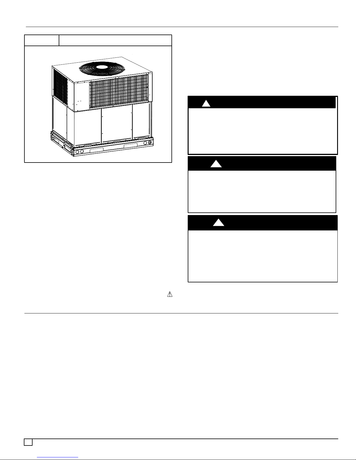
FIGURE 1
PACKAGED GAS / ELECTRIC UNIT
SAFETY CONSIDERATIONS
Improper installation adjustment, alteration, service,
maintenance, or use can cause explosion, fire, electrical shock,
or other conditions which may cause death, personal injury, or
property damage. Consult a qualified installer, service agency, or
your distributor or branch for information or assistance. The
qualified installer or agency must use factory−authorized kits or
accessories when modifying this product Refer to the individual
instructions packaged with the kits or accessories when
installing.
Follow all safety codes. Wear safety glasses, protective clothing,
and work gloves. Have a fire extinguisher available. Read these
instructions thoroughly and follow all warnings or cautions
included in literature and attached to the unit. Consult local
building codes, the current editions of the National Fuel Gas
Code (NFGC 54/ANSI Z223.1, and the National Electrical Code
(NEC) NFPA 70.
In Canada refer to the current editions of the National Standards
of Canada CAN/CSA−B149.1 and .2 Natural Gas and Propane
Installation codes, and Canadian electrical Code CSA C22.1.
manuals, be alert to the potential for personal injury. Understand
these signal words: DANGER, WARNING, and CAUTION.
These words are used with the safety−alert symbol. DANGER
identifies the most serious hazards which will result in severe
personal injury or death. WARNING signifies hazards which
could result in personal injury or death. CAUTION is used to
identify unsafe practices which may result in minor personal
injury or product and property damage. NOTE is used to
highlight suggestions which will result in enhanced installation,
reliability, or operation.
!
CUT HAZARD
Failure to follow this caution may result in personal injury.
When removing access panels or performing maintenance
functions inside your unit, be aware of sharp sheet metal parts
and screws. Although special care is taken to reduce sharp
edges to a minimum, be extremely careful when handling
parts or reaching into the unit.
!
ELECTRICAL SHOCK HAZARD
Failure to follow this warning could result in personal injury or
death.
Before installing or servicing system, always turn off main
power to system. There may be more than one disconnect
switch. TAG DISCONNECT SWITCH WITH LOCKOUT TAG.
!
FIRE, EXPLOSION, ELECTRICAL SHOCK AND
CARBON MONOXIDE POISONING HAZARD
Failure to follow this warning could result in personal injury
or unit damage.
A qualified installer or agency must use only
factory−authorized kits or accessories when modifying this
product.
CAUTION
WARNING
WARNING
Recognize safety information. This is the safety−alert symbol
When you see this symbol on the unit and in instructions or
INTRODUCTION
The PGD5 / PGS5 units (see Fig. 1) are a fully self−contained,
combination Category I gas heating/electric cooling unit
designed for outdoor installation (See Fig. 3 and 4 for unit
dimensions). All unit sizes have return and discharge openings
for both horizontal and downflow configurations, and are factory
shipped with all downflow duct openings covered. Units may be
installed either on a rooftop or on a cement slab. (See Fig. 5 for
roof curb dimensions).
2
.
Models with the number “1” in the 13th position of the model
number are dedicated Low NOx units designed for California
installations. These models meet the California maximum oxides
of nitrogen (NOx) emissions requirements of 40 nanograms/joule
or less as shipped from the factory and must be installed in
California Air Quality Management Districts or any other regions
in North America where a Low NOx rule exists.
NOTE:Low NOx requirements apply only to natural gas
installations.
In gas heating mode, this unit is designed for a minimum
continuous return−air temperature of 55°F (13°C) db and a
maximum continuous return−air temperature of 80°F (27°C) db.
Failure to follow these return−air temperature limits may affect
reliability of heat exchangers, motors, and other components.
462 01 2103 01
RECEIVING AND INSTALLATION
STEP 1 — Check Equipment
Identify Unit
The unit model number and serial number are stamped on the unit
information plate. Check this information against shipping papers.
Inspect Shipment
Inspect for shipping damage before removing packaging materials.
If unit appears to be damaged or is torn loose from its anchorage,
have it examined by transportation inspectors before removal.
Forward claim papers directly to transportation company.
Manufacturer is not responsible for any damage incurred in transit.
Check all items against shipping list. Immediately notify the nearest
equipment distribution office if any item is missing. To prevent loss
or damage, leave all parts in original packages until installation.
STEP 2 — Provide Unit Support
IMPORTANT: The unit must be secured to the curb by installing
screws through the bottom of the curb flange and into the unit base
rails. When installing large base units onto the common curb, the
screws must be installed before allowing the full weight of the unit
to rest on the curb. A minimum of six screws are required for large
base units. Failure to secure unit properly could result in an
unstable unit. See Warning near Rigging/Lifting information and
accessory curb instructions for more details.
For hurricane tie downs, contact distributor for details and PE
(Professional Engineering) Certificate if required.
IMPORTANT: The gasketing of the unit to the roof curb is critical
for a water tight seal. Install gasketing material supplied with the
roof curb. Improperly applied gasketing also can result in air
leaks and poor unit performance.
Curb should be level to within 1/4 in. (6 mm). This is necessary
for unit drain to function properly. Refer to accessory roof curb
installation instructions for additional information as required.
Roof Curb
Install accessory roof curb in accordance with instructions shipped
with curb. See Fig. 5. Install insulation, cant strips, roofing, and
flashing. Ductwork must be attached to curb.
Accessory kits are available to aid in installing a new metal base
rail unit on an old roof curb.
Accessory kit number CPADCURB001A00, (small chassis) and
accessory kit number CPADCURB002A00, (large chassis)
includes roof curb adapter and gaskets for the perimeter seal
and duct openings. No additional modifications to curb are
required when using this kit.
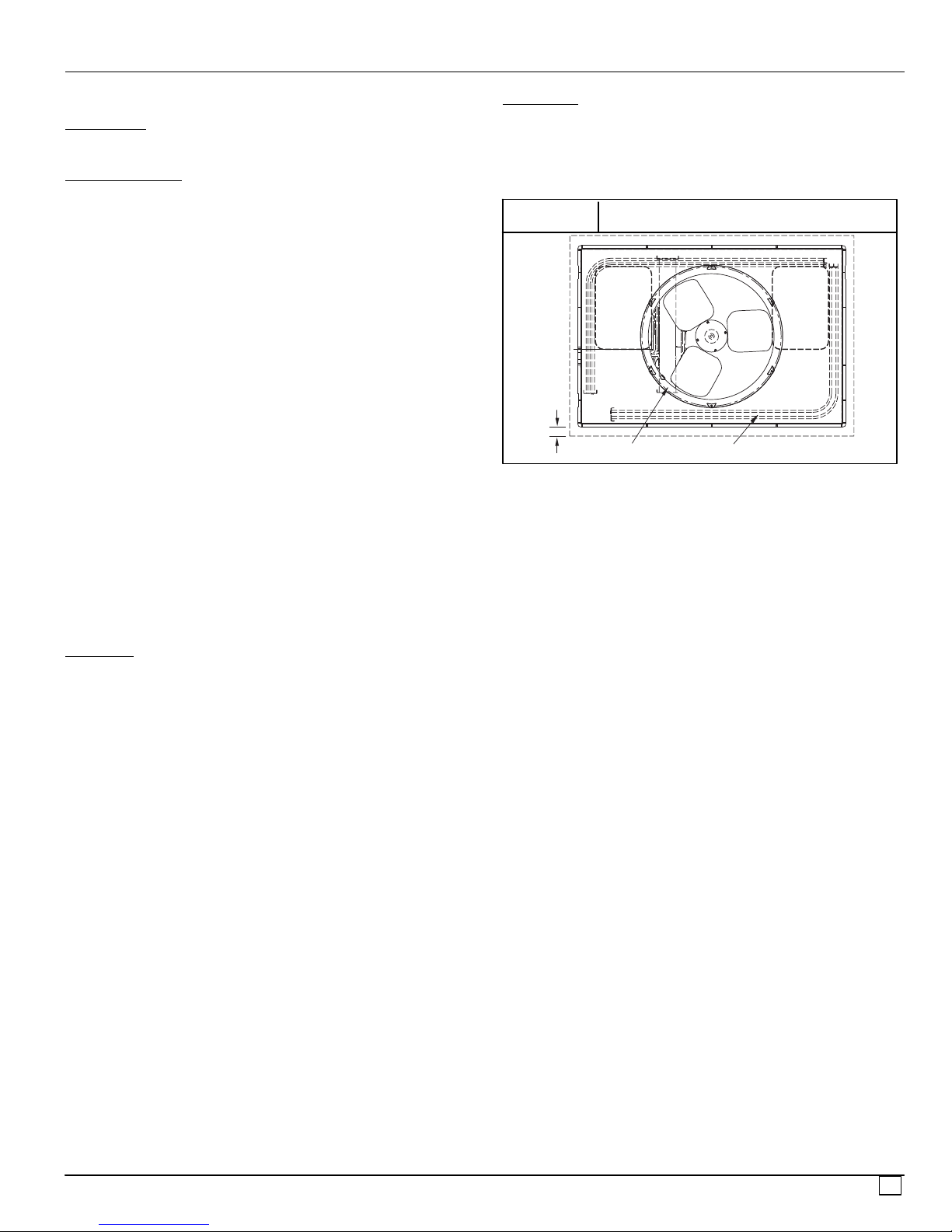
Slab Mount
Place the unit on a solid, level concrete pad that is a minimum of 4”
(102mm) thick with 2” (51mm) above grade (see Figure 2). The slab
should extend approximately 2” beyond the casing on all 4 sides of
the unit. Do not secure the unit to the slab except when required by
local codes.
FIGURE 2
2"
EVAP. COIL COND. COIL
Slab Mounting Details
OPTIONAL
RETURN
AIR
OPENING
OPTIONAL
SUPPLY
AIR
OPENING
STEP 3 — Field Fabricate Ductwork
Secure all ducts to roof curb and building structure on vertical
discharge units. Do not connect ductwork to unit. For horizontal
applications, unit is provided with flanges on the horizontal
openings. All ductwork should be secured to the flanges. Insulate
and weatherproof all external ductwork, joints, and roof openings
with counter flashing and mastic in accordance with applicable
codes.
Ducts passing through an unconditioned space must be insulated
and covered with a vapor barrier.
If a plenum return is used on a vertical unit, the return should be
ducted through the roof deck to comply with applicable fire codes.
A minimum clearance is not required around ductwork. Cabinet
return−air static shall not exceed −.25 inches water column.
462 01 2103 01
3
4
462 01 2103 01
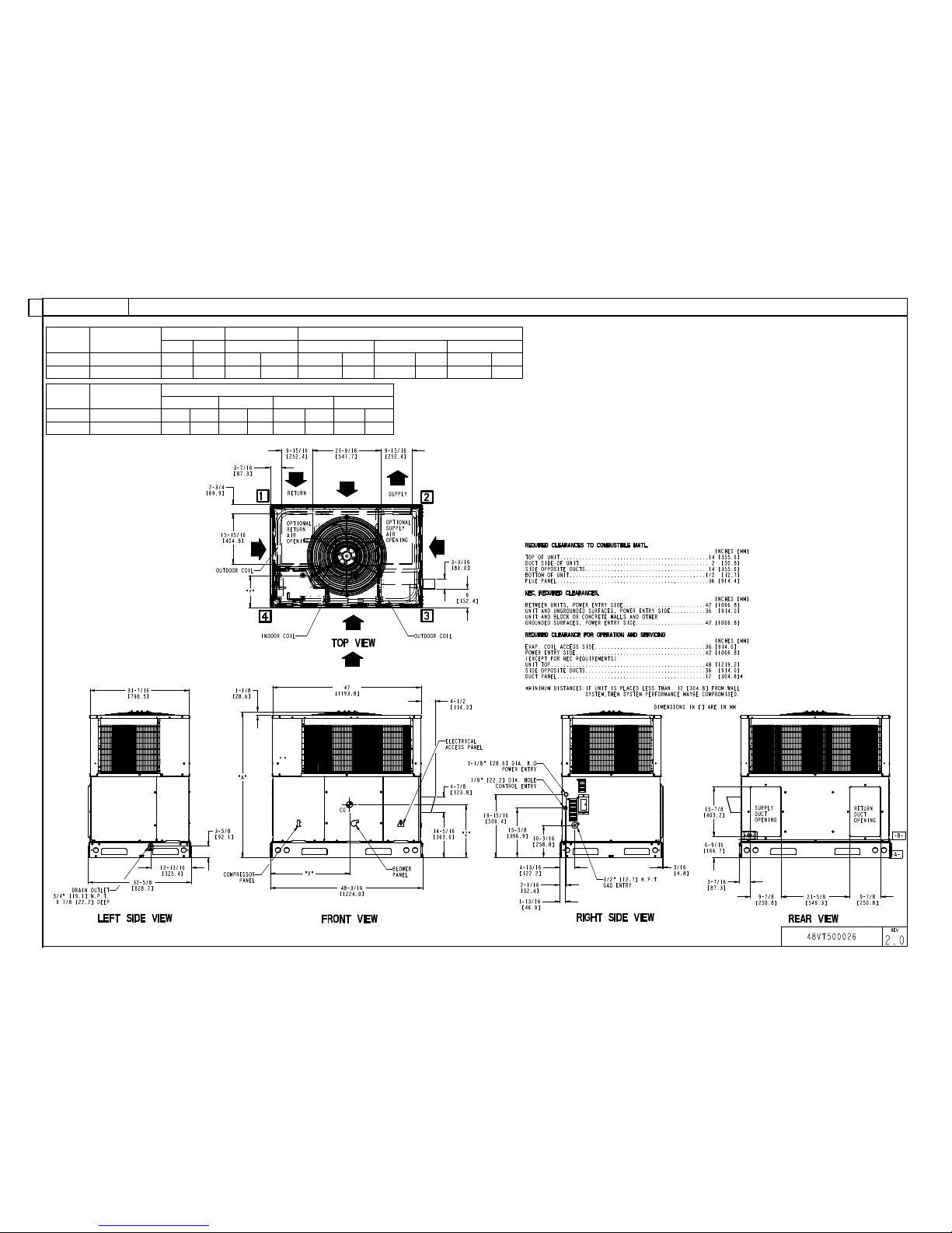
Unit
Electrical
Characteristics
Unit WT. Unit HT. Center of Gravity
LB KG A X Y Z
24040 208/230-1-60 419 189.9 44-3/4 1136.7 22-13/16 579.4 15-5/16 388.9 17-5/8 447.7
24060 208/230-1-60 426 193.1 44-3/4 1136.7 22-13/16 579.4 15-5/16 388.9 17-5/8 447.7
UNIT Voltage
Corner Weight LB/KG
1 2 3 4
24040 208/230 62.8 28.5 83.8 38.0 125.6 57.0 146.6 66.5
24060 208/230 63.6 28.9 84.8 38.5 127.1 57.7 148.3 67.3
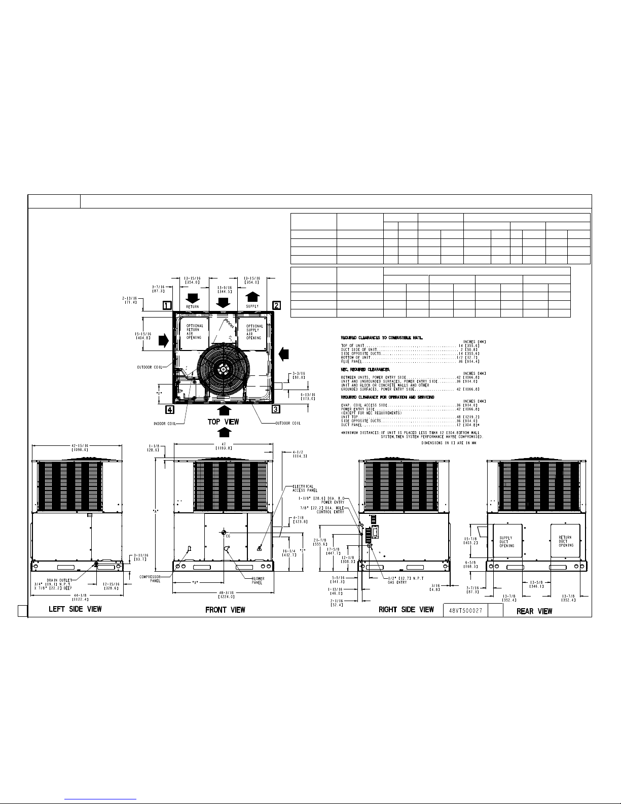
FIGURE 3
Model Size 24 Dimensions
5
462 01 2103 01
Unit
Electrical
Characteristics
Unit WT. Unit HT. Center of Gravity
LB KG A X Y Z
36060 208/230-1-60 513 232.8 48-5/8 1235.1 22-13/16 579.4 18 457.2 16-5/8 422.3
36090 208/230-1-60 521 236.4 48-5/8 1235.1 22-13/16 579.4 18 457.2 16-5/8 422.3
48090 / 115 / 130 208/230-1-60 549 249.1 50-5/8 1285.9 22-13/16 579.4 18 457.2 17-5/8 447.7
60090 / 115 / 130 208/230-1-60 600 272.3 54-5/8 1387.5 22-13/16 579.4 18 457.2 18 457.2
Unit Voltage
Corner Weight LB/KG
1 2 3 4
36060 208/230 77.0 35.0 102.6 46.6 154.0 69.9 179.6 81.6
36090 208/230 78.2 35.5 104.2 47.3 156.4 71.0 182.4 82.8
48090 / 115 / 130 208/230 82.4 37.4 109.8 49.9 164.8 74.8 192.2 87.3
60090 / 115 / 130 208/230 90.0 40.9 120.0 54.5 180.1 81.8 210.1 95.4
FIGURE 4
Model Size 36−60 Dimensions
2
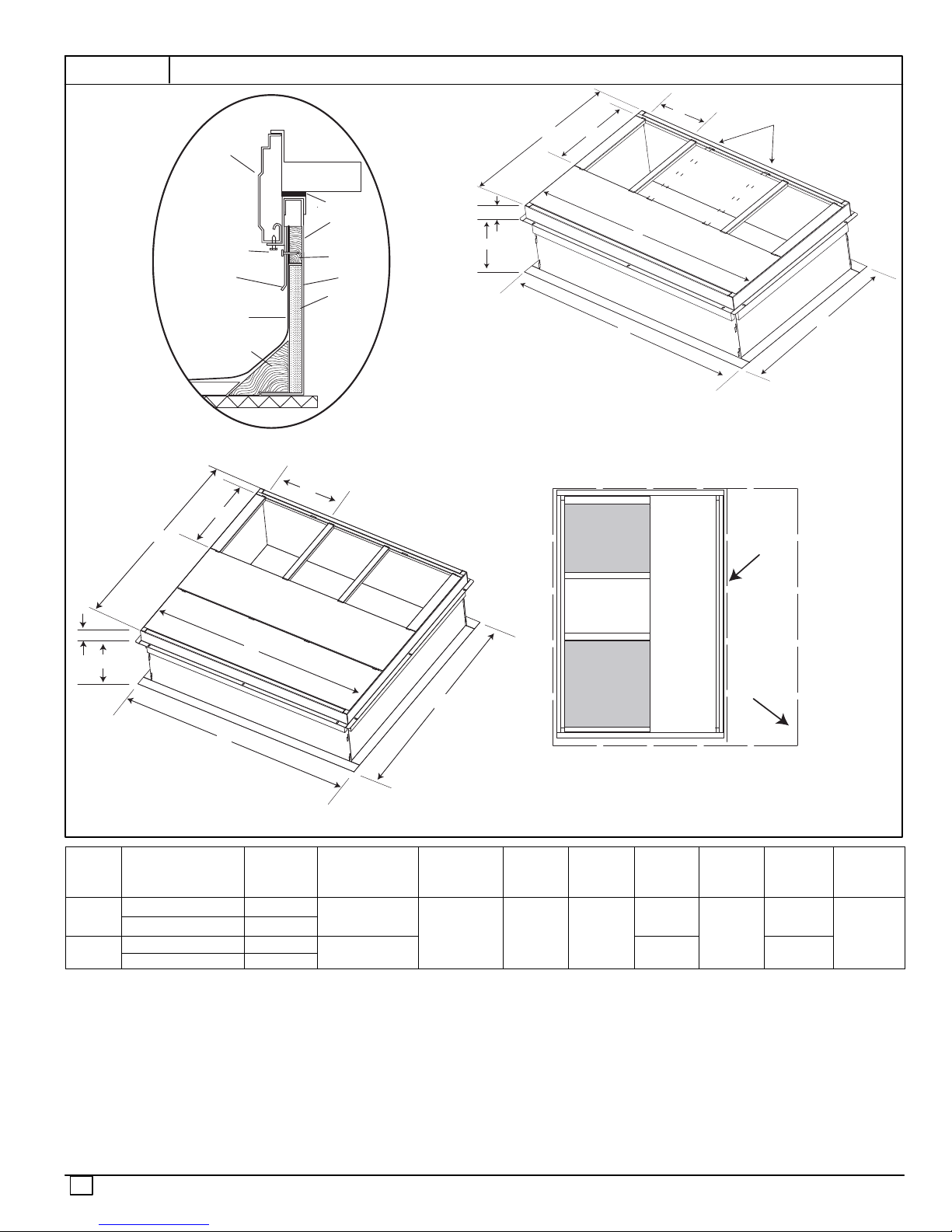
FIGURE 5
Roof Curb Dimensions
G
HVAC unit
base rails
Anchor screw
field supplied
Flashing field
supplied
Roofing material
field supplied
Cant strip
field supplied
*Provided with roofcurb
HVAC unit
basepan
ROOF CURB DETAIL
B
C
Sealing
*
Gasket
Roofcurb
Wood nailer*
(field supplied)
G
C
F
A
SMALL/COMMON CURB
SUPPLY
AIR
B
H
D
Dashed lines show cross support
location for large basepan units.
E
SMALL
BASE
UNIT
A
F
D
LARGE CURB
H
UNIT
SIZE
Small
or
Large
Large
NOTES:
1. Roof curb must be set up for unit being installed.
2. Seal strip must be applied, as required, to unit being installed.
3. Roof curb is made of 16−gauge steel.
4. Attach ductwork to curb (flanges of duct rest on curb).
5. Insulated panels: 1−in. (25 mm) thick fiberglass 1 lb. density.
CATALOG
NUMBER
A
IN. (mm)
CPRFCURB010A00 11 (279)
CPRFCURB011A00 14 (356)
CPRFCURB012A00 11 (279)
CPRFCURB013A00 14 (356)
(small/common
IN. (mm)*
10 (254)
14 (356)
B
base)
E
B
(large base)
IN. (mm)*
14 (356) 16 (406)
IN. (mm)DIN. (mm)EIN. (mm)FIN. (mm)GIN. (mm)HIN. (mm)
LARGE
RETURN
AIR
BASE
UNIT
UNIT PLACEMENT ON
COMMON CURB
SMALL OR LARGE BASE UNIT
C
47.8
(1214)
32.4 (822)
43.9
(1116)
2.7 (69)
30.6 (778)
42.2
(1072)
46.1 (1170)
6
462 01 2103 01
STEP 4 — Provide Clearances
The required minimum operating and service clearances are
shown in Fig. 3 and 4. Adequate combustion, ventilation and
condenser air must be provided.
IMPORTANT: Do not restrict outdoor airflow. An air restriction at
either the outdoor−air inlet or the fan discharge may be
detrimental to compressor life.
The condenser fan pulls air through the condenser coil and
discharges it through the top grille. Be sure that the fan
discharge does not recirculate to the condenser coil. Do not
locate the unit in either a corner or under an overhead
obstruction. The minimum clearance under a partial overhang
(such as a normal house overhang) is 48−in. (1219 mm) above
the unit top. The maximum horizontal extension of a partial
overhang must not exceed 48−in. (1219 mm).
Do not place the unit where water, ice, or snow from an
overhang or roof will damage or flood the unit. Do not install the
unit on carpeting or other combustible materials. Slab−mounted
units should be at least 4 in. (102 mm) above the highest
expected water and runoff levels. Do not use unit if it has been
under water.
STEP 5 — Rig and Place Unit
Rigging and handling of this equipment can be hazardous for many
reasons due to the installation location (roofs, elevated structures,
etc.).
Only trained, qualified crane operators and ground support staff
should handle and install this equipment.
When working with this equipment, observe precautions in the
literature, on tags, stickers, and labels attached to the equipment,
and any other safety precautions that might apply.
Training for operators of the lifting equipment should include, but
not be limited to, the following:
1. Application of the lifter to the load, and adjustment of the lifts to
adapt to various sizes or kinds of loads.
2. Instruction in any special operation or precaution.
3. Condition of the load as it relates to operation of the lifting kit,
such as balance, temperature, etc.
Follow all applicable safety codes. Wear safety shoes and
work gloves.
INSPECTION
Prior to initial use, and at monthly intervals, all rigging shackles,
clevis pins, and straps should be visually inspected for any
damage, evidence of wear, structural deformation, or cracks.
Particular attention should be paid to excessive wear at hoist
hooking points and load support areas. Materials showing any kind
of wear in these areas must not be used and should be discarded.
!
WARNING
UNIT FALLING HAZARD
Failure to follow this warning could result in personal
injury or death.
Never stand beneath rigged units or lift over people.
Rigging/Lifting of Unit
!
WARNING
PROPERTY DAMAGE HAZARD
Failure to follow this warning could result in personal
injury/death or property damage.
When straps are taut, the clevis should be a minimum of
36 in. (914 mm) above the unit top cover.
!
WARNING
UNIT FALLING HAZARD
Failure to follow this warning could result in personal
injury or death.
Large base units must be secured to common curb
before allowing full weight of unit to rest on curb. Install
screws through curb into unit base rails while rigging
crane is still supporting unit.
Lifting holes are provided in base rails as shown in Fig. 3 and 4.
1. Leave top shipping skid on the unit for use as a spreader bar to
prevent the rigging straps from damaging the unit. If the skid is
not available, use a spreader bar of sufficient length to protect
the unit from damage.
2. Attach shackles, clevis pins, and straps to the base rails of the
unit. Be sure materials are rated to hold the weight of the unit
(See Fig. 6).
3. Attach a clevis of sufficient strength in the middle of the straps.
Adjust the clevis location to ensure unit is lifted level with the
ground.
After the unit is placed on the roof curb or mounting pad, remove
the top crating.
462 01 2103 01
7
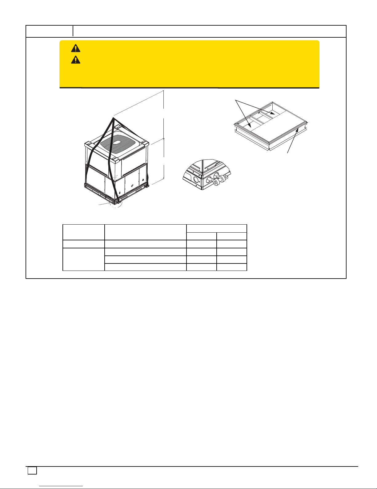
FIGURE 6
Unit Corner Weight (lbs) and Rigging
CAUTION - NOTICE TO RIGGERS
PRUDENCE - AVIS AUX MANIPULATEUR
ACCESS PANELS MUST BE IN PLACE WHEN RIGGING.
PANNEAUX D'ACCES DOIT ÊTRE EN PLACE POUR MANIPULATION.
Use top skid as spreader bar. / Utiliser la palette du haut comme barre de répartition
DUCTS
MINIMUM HEIGHT: 36" (914.4 mm)
HAUTEUR MINIMUM
UNIT HEIGHT
HAUTEUR D'UNITÉ
DETAIL A
SEE DETAIL A
VOIR DÉTAIL A
VOIR DÉTAIL A
Rigging Weight
Cabinet MODEL NUMBER
lb kg
Small PG(D,S)524 431 196
PG(D,S)536 530 240
Large
PG(D,S)548 558 253
PG(D,S)560 609 276
SEAL STRIP MUST BE IN
PLACE BEFORE PLACING
UNIT ON ROOF CURB
BANDE SCELLANT DOIT ÊTRE
EN PLACE AVANT DE PLACER
L'UNITÉ SUR LA BASE DE TOIT
50CY502286 2.0
8
462 01 2103 01
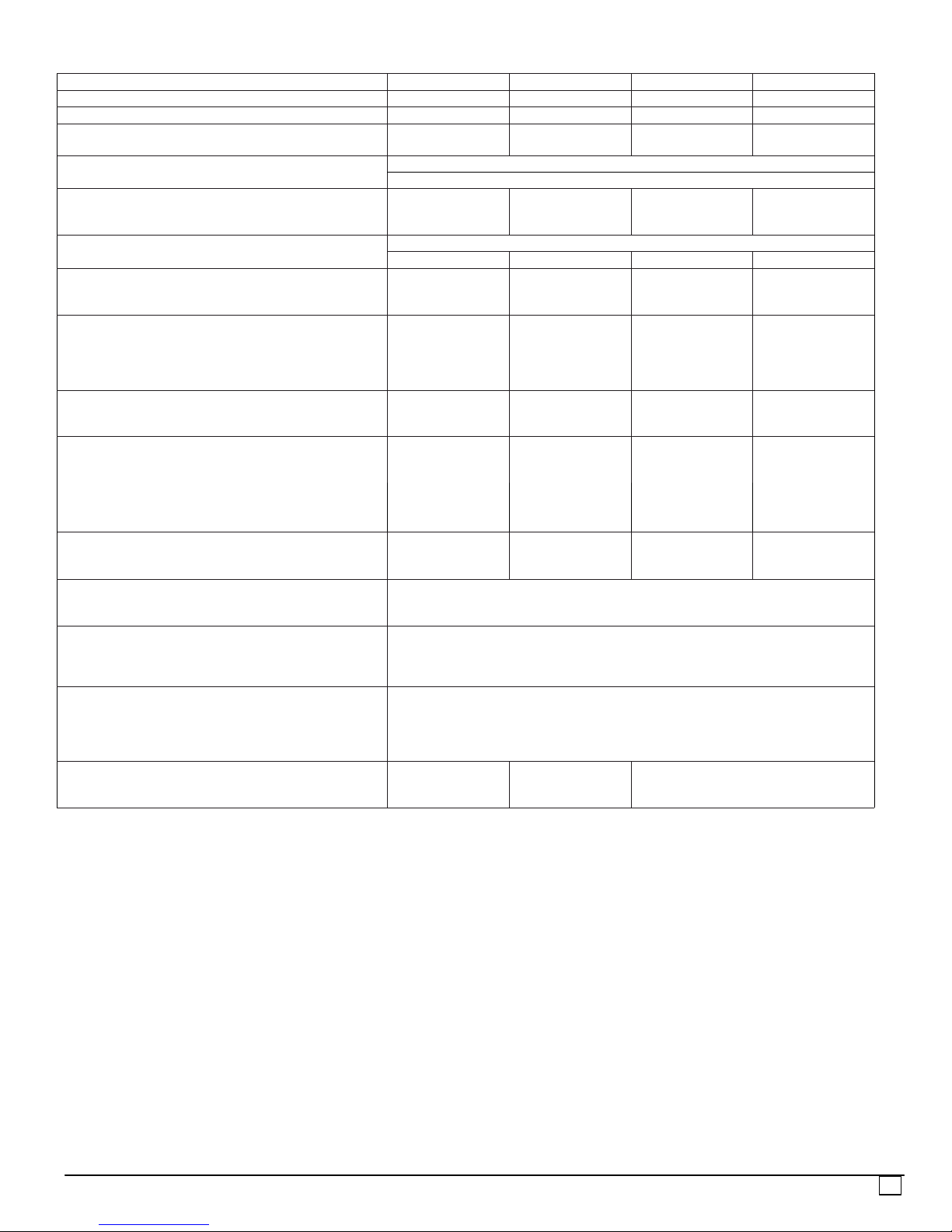
Table 1 − PHYSICAL DATA PG(D,S)524−36
UNIT SIZE 24040 24060 36060 36090
NOMINAL COOLING CAPACITY (ton) 2 2 3 3
NOMINAL HEATING CAPACITY (Btu) 40,000 60,000 60,000 90,000
SHIPPING WEIGHT (lb)
(kg)
COMPRESSORS
Quantity
REFRIGERANT: R−410A
Quantity (lb)
(kg)
REFRIGERANT METERING DEVICE TXV
Size 2 Ton 2 Ton 3 Ton 3 Ton
OUTDOOR COIL
Rows...Fins/in.
Face Area (sq ft)
OUTDOOR FAN
Nominal Cfm
Diameter (in.)
(mm)
Motor Hp (Rpm)
INDOOR COIL
Rows...Fins/in.
Face Area (sq ft)
INDOOR FAN
Nominal Low Stage Cooling Airflow (Cfm)
Nominal High Stage Cooling Airflow (Cfm)
Size (in.)
(mm)
Motor HP (RPM) 1/2 1/2 3/4 3/4
FURNACE SECTION*
Burner Orifice No. (Qty...Drill Size)
Natural Gas
HIGH−PRESSURE SWITCH (psig) Cut−out
Reset (Auto)
HIGH−PRESSURE SWITCH 2 (psig)
(Compressor Solenoid)
Cut−out
Reset (Auto)
LOSS−OF−CHARGE /
LOW−PRESSURE SWITCH
(Liquid Line) (psig)
Cut−out
Reset (auto)
RETURN−AIR FILTERS Throwaway†
(in.)
(mm)
Continued next page.
426
193
10.1
4.6
2...21
13.6
2700
22
559
1/8 (825)
3...17
3.7
600
800
10x10
254x254
2...44 2...38 2...38 3...38
20x20x1
508x508x25
431
196
2−Stage Scroll
10.1
4.6
2...21
13.6
2700
22
559
1/8 (825)
3...17
3.7
600
800
10x10
254x254
20x24x1
508x610x25
522
237
1
9.5
4.3
2...21
17.5
2800
22
559
1/8 (825)
3...17
4.7
850
1200
11x10
279x254
670 ±10
470 ± 25
565 ± 15
455 ± 15
23 ± 5
55 ± 5
24x30x1
610x762x25
530
240
9.5
4.3
2...21
17.5
2800
22
559
1/8 (825)
3...17
4.7
850
1200
11x10
279x254
462 01 2103 01
9
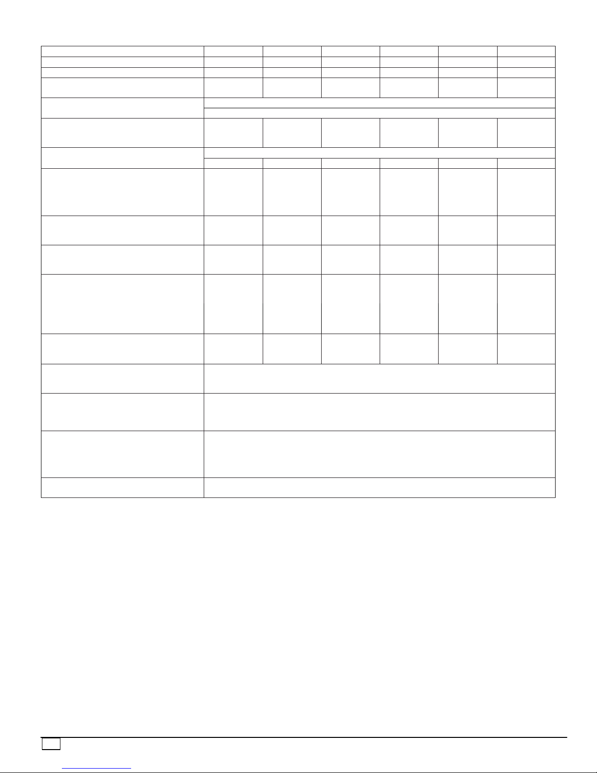
Table 2—Physical Data PG(D,S)548−60
UNIT SIZE 48090 48115 48130 60090 60115 60130
4 4 4 5 5 5
NOMINAL HEATING CAPACITY (Btu) 90,000 115,000 130,000 90,000 115,000 130,000
SHIPPING WEIGHT (lb)
(kg)
COMPRESSORS
Quantity
REFRIGERANT: R−410A
Quantity (lb)
(kg)
REFRIGERANT METERING DEVICE TXV
Size 4 Ton 4 Ton 4 Ton 5 Ton 5 Ton 5 Ton
OUTDOOR FAN
Nominal Cfm
Diameter (in.)
(mm)
Motor Hp (Rpm)
OUTDOOR COIL
Rows...Fins/in.
Face Area (sq ft)
INDOOR COIL
Rows...Fins/in.
Face Area (sq ft)
INDOOR FAN
Nominal Low Stage Cooling Airflow (Cfm)
Nominal High Stage Cooling Airflow (Cfm)
Size (in.)
(mm)
Motor HP (RPM) 1 1 1 1 1 1
FURNACE SECTION*
Burner Orifice No. (Qty...Drill Size)
Natural Gas
HIGH−PRESSURE SWITCH (psig)
Cut−out
Reset (Auto)
HIGH−PRESSURE SWITCH 2 (psig)
(Compressor Solenoid)
Cut−out
Reset (Auto)
LOSS−OF−CHARGE /
LOW−PRESSURE SWITCH
(Liquid Line) (psig)
Cut−out
Reset (auto)
RETURN−AIR FILTERS Throwaway† (in.)
(mm)
*Based on altitude of 0 to 2000 ft (0 to 610 m).
Recommended filter sizes for field-installed air filter grilles mounted on the wall or ceiling of the conditioned structure. Required filter sizes shown are based on the larger
of the ARI (Air Conditioning and Refrigeration Institute) rated cooling airflow or the heating airflow velocity of 300 ft/minute for throwaway type or 450 ft/minute for
high-capacity type. Air filter pressure drop for non-standard filters must not exceed 0.08 IN. W.C.
558
253
558
253
558
253
609
276
609
276
2−Stage Scroll
1
15.3
6.9
3300
22
559
1/4 (1100)
2...21
19.4
3...17
5.7
1100
1600
11x10
279x254
15.3
6.9
3300
22
559
1/4 (1100)
2...21
19.4
3...17
5.7
1100
1600
11x10
279x254
15.3
6.9
3300
22
559
1/4 (1100)
2...21
19.4
3...17
5.7
1100
1600
11x10
279x254
15.8
7.2
3300
22
559
1/3 (1110)
2...21
23.3
4...17
5.7
1200
1750
11x10
279x254
15.8
7.2
3300
22
559
1/3 (1110)
2...21
23.3
4...17
5.7
1200
1750
11x10
279x254
1/3 (1110)
279x254
3...38 3...33 3...31 3...38 3...33 3...31
670 ± 10
470 ± 25
565 ± 15
455 ± 15
23 ± 5
55
± 5
24x36x1
610x914x25
609
276
15.8
7.2
3300
22
559
2...21
23.3
4...17
5.7
1200
1750
11x10
10
462 01 2103 01
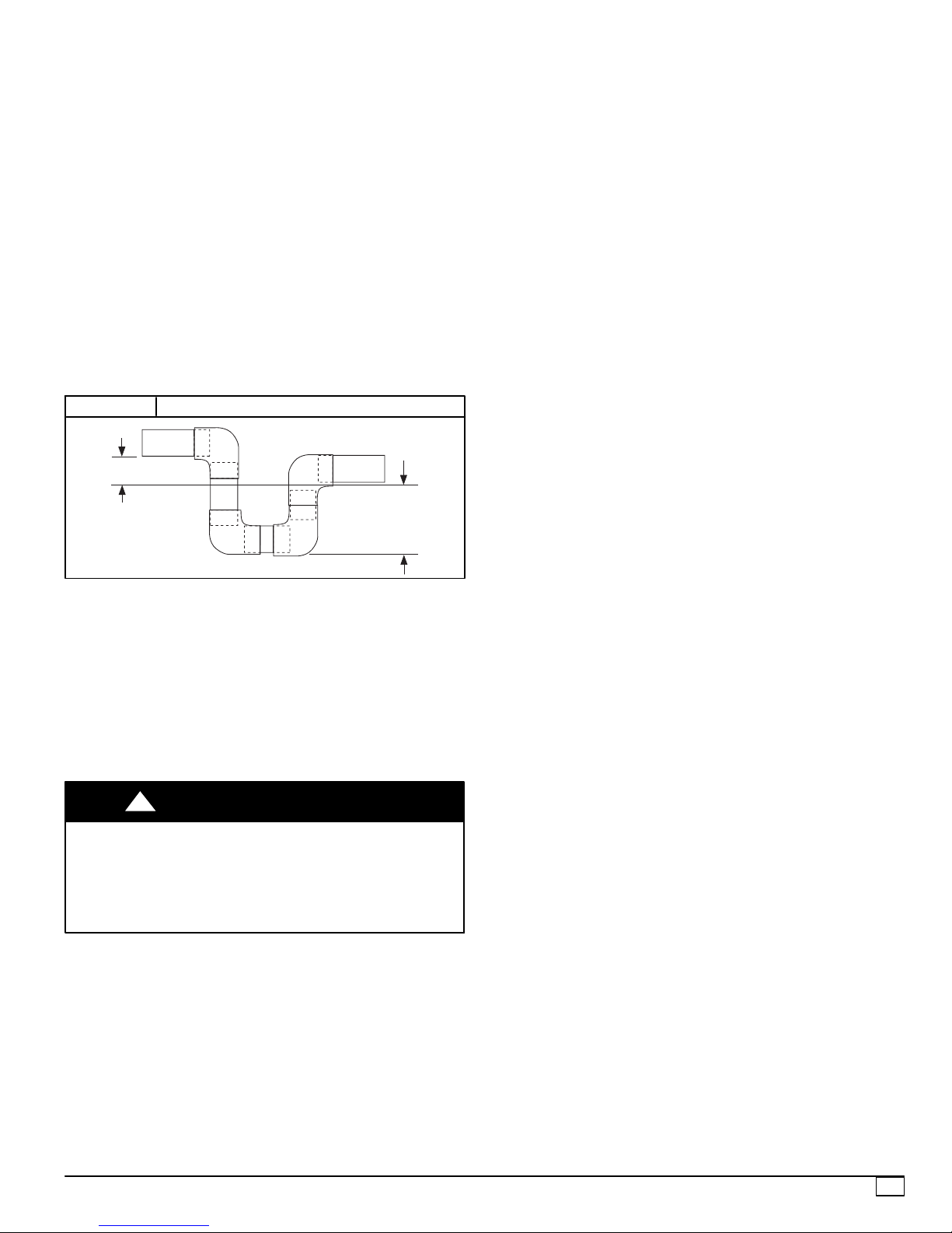
STEP 6 — Connect Condensate Drain
NOTE: When installing condensate drain connection be sure to
comply with local codes and restrictions.
Unit disposes of condensate water through a 3/4 in. NPT fitting
which exits through the base on the evaporator coil access side.
See Fig. 3 & 4 for location.
Condensate water can be drained directly onto the roof in rooftop
installations (where permitted) or onto a gravel apron in ground
level installations. Install a field−supplied 2−in. (51 mm)
condensate trap at the end of condensate connection to ensure
proper drainage. Make sure that the outlet of the trap is at least 1
in. (25 mm) lower than the drain−pan condensate connection to
prevent the pan from overflowing (See Fig. 7). Prime the trap
with water. When using a gravel apron, make sure it slopes away
from the unit.
Connect a drain tube using a minimum of 3/4−in. PVC or 3/4−in.
copper pipe (all field−supplied) at the outlet end of the 2−in. (51
mm) trap. Do not undersize the tube. Pitch the drain tube
downward at a slope of at least 1−in. (25 mm) for every 10 ft (3.1
m) of horizontal run. Be sure to check the drain tube for leaks.
FIGURE 7
1-in. (25 mm) min.
Condensate Trap
TRAP
OUTLET
2-in. (51 mm) min.
STEP 7 — Install Flue Hood
The flue assembly is secured and shipped in the return air duct.
Remove duct cover to locate the assembly (See Fig. 9).
NOTE:Dedicated low NOx models MUST be installed in
California Air Quality Management Districts where a Low NOx
rule exists.
These models meet the California maximum oxides of nitrogen
(NOx) emissions requirements of 40 nanograms/joule or less as
shipped from the factory.
NOTE:Low NOx requirements apply only to natural gas
installations.
!
WARNING
CARBON MONOXIDE POISONING HAZARD
Failure to follow this warning could result in personal injury or
death.
The venting system is designed to ensure proper venting. The
flue hood assembly must be installed as indicted in this section
of the unit installation instructions.
Install the flue hood as follows:
1. This installation must conform with local building codes
and with NFPA 54/ANSI Z223.1 National Fuel Gas Code
(NFGC), (in Canada, CAN/CGA B149.1, and B149.2)
latest revision. Refer to Provincial and local plumbing or
wastewater codes and other applicable local codes.
2. Remove flue hood from shipping location (inside the return
section of the blower compartment−see Fig. 9). Remove
the return duct cover to locate the flue hood. Place flue
hood assembly over flue panel. Orient screw holes in flue
hood with holes in the flue panel.
3. Secure flue hood to flue panel by inserting a single screw
on the top flange and the bottom flange of the hood.
Step 8 — Install Gas Piping
The gas supply pipe enters the unit through the access hole
provided. The gas connection to the unit is made to the 1/2−in.
(12.7 mm) FPT gas inlet on the gas valve.
Install a gas supply line that runs to the heating section. Refer to
the NFGC for gas pipe sizing. Do not use cast−iron pipe. It is
recommended that a black iron pipe is used. Check the local
utility for recommendations concerning existing lines. Size gas
supply piping for 0.5 in. wc maximum pressure drop. Never use
pipe smaller than the 1/2−in. (12.7 mm) FPT gas inlet on the unit
gas valve.
For natural gas applications, the gas pressure at unit gas
connection must not be less than 4.0 in. wc or greater than 13 in.
wc while the unit is operating. For propane applications, the gas
pressure must not be less than 11.0 in. wc or greater than 13 in.
wc at the unit connection.
A 1/8−in. (3.2 mm) NPT plugged tapping, accessible for test
gauge connection, must be installed immediately upstream of the
gas supply connection to the gas valve.
When installing the gas supply line, observe local codes
pertaining to gas pipe installations. Refer to the NFPA 54/ANSI
Z223.1 latest edition (in Canada, CAN/CGA B149.1).
NOTE:In the state of Massachusetts:
1. Gas supply connections MUST be performed by a
licensed plumber or gas fitter.
2. When flexible connectors are used, the maximum length
shall not exceed 36 inches (915 mm).
3. When lever handle type manual equipment shutoff valves
are used, they shall be T−handle valves.
4. The use of copper tubing for gas piping is NOT approved
by the state of Massachusetts.
In the absence of local building codes, adhere to the following
pertinent recommendations:
1. Avoid low spots in long runs of pipe. Grade all pipe 1/4 in.
(6.35 mm) for every 15 ft (4.6 m) of length to prevent
traps. Grade all horizontal runs downward to risers. Use
risers to connect to heating section and to meter.
2. Protect all segments of piping system against physical and
thermal damage. Support all piping with appropriate
straps, hangers, etc. Use a minimum of one hanger every
6 ft (1.8 m). For pipe sizes larger than 1/2 in., follow
recommendations of national codes.
3. Apply joint compound (pipe dope) sparingly and only to
male threads of joint when making pipe connections. Use
only pipe dope that is resistant to action of liquefied
petroleum gases as specified by local and/or national
codes. Never use Teflon tape.
4. Install sediment trap in riser leading to heating section
(See Fig. 8). This drip leg functions as a trap for dirt and
condensate.
5. Install an accessible, external, manual main shutoff valve
in gas supply pipe within 6 ft (1.8 m) of heating section.
6. Install ground−joint union close to heating section between
unit manual shutoff and external manual main shut−off
valve.
7. Pressure test all gas piping in accordance with local and
national plumbing and gas codes before connecting piping
to unit.
8. Check for gas leaks at the field−installed and
factory−installed gas lines after all piping connections
have been completed. Use a commercially available soap
solution (or method specified by local codes and/or
regulations).
462 01 2103 01
11
 Loading...