

Installation Instructions
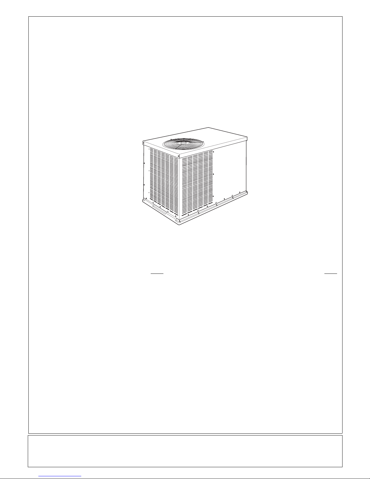
WTA3 & PAT3 Series
PACKAGED AIR CONDITIONER
TABLE OF CONTENTS
Page
SAFE INSTALLATION REQUIREMENTS 2........
INTRODUCTION 2.............................
RECEIVING AND INSTALLATION 2...............
Check Equipment 2...........................
Provide Unit Support 2 -- 3.....................
Install Duct Connections 3.....................
Dimensions 4................................
Connect Condensate Drain 5..................
Install Electrical Connections 5 -- 10............
PRE--START--UP 11............................
START--UP 11..................................
Check for Refrigerant Leaks 11.................
Start--Up Cooling & Make Adjustments 11 -- 12..
Check and Adjust Charge 12 -- 14............
Airflow 15..................................
Sequence of Operation 15 -- 16..............
Page
MAINTENANCE 16.............................
Air Filter 16..................................
Unit Top Removal 16..........................
Indoor Blower and Motor 17....................
Outdoor & Indoor Coil, Condensate Drain Pan 17.
Outdoor Fan 17..............................
Electrical Controls and Wiring 18...............
Refrigeration Circuit 18........................
Evaporator Airflow 18.........................
Metering Devices 18..........................
Liquid Line Strainers 18.......................
High Flow Valves 18..........................
AIRFLOW CHARTS 19 -- 20.....................
COOLING TROUBLESHOOTING GUIDE 21.......
CHECKLIST FORM 22..........................
International Comfort Products, LLC
Lewisburg, TN. 37091
Printed in U.S.A.
426 01 1302 00 11--18--08
SAFE INSTALLATION REQUIREMENTS
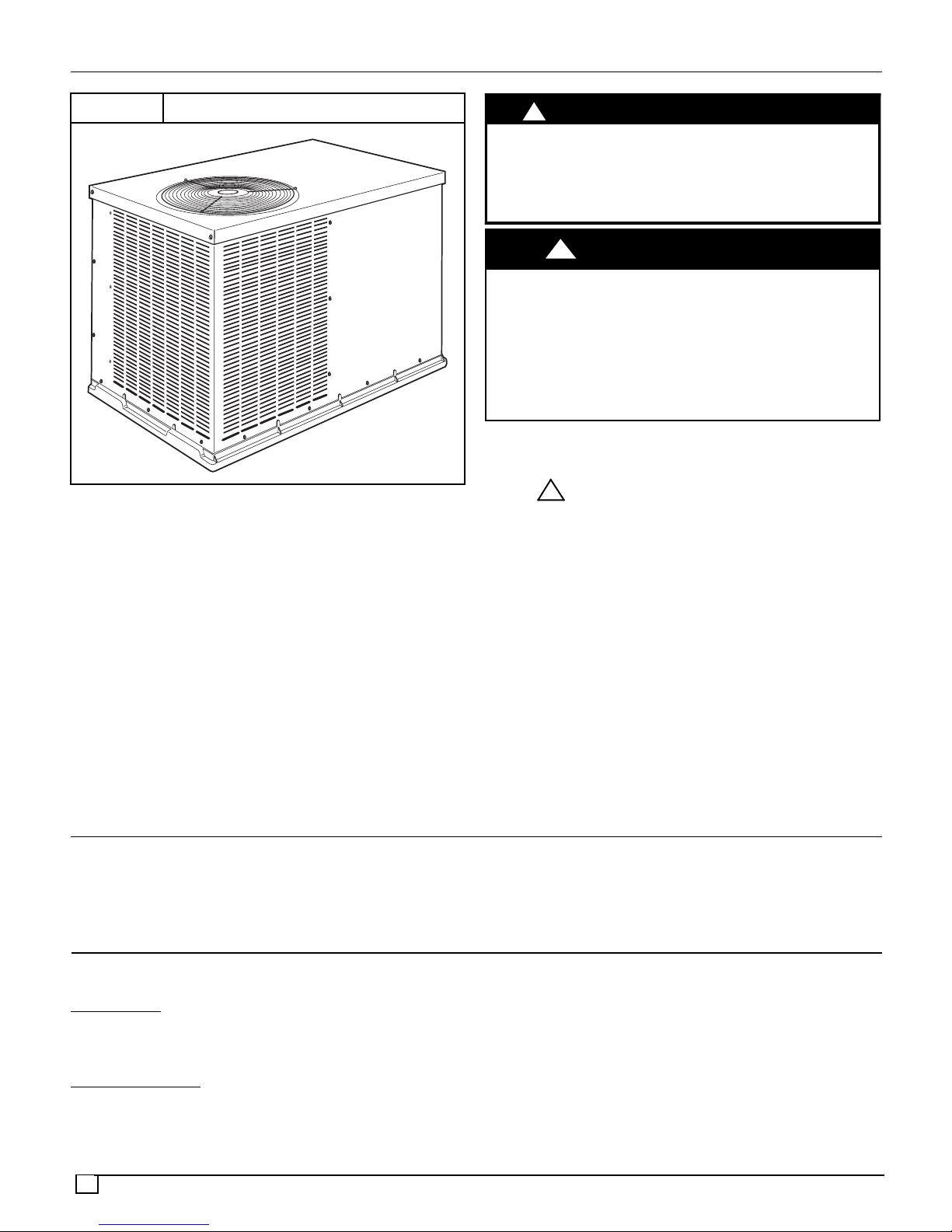
FIGURE 1
Installation and servicing of this equipment can be
hazardous due to mechanical and electrical components.
Only trained and qualified personnel should install, repair,
or service this equipment.
Untrained personnel can perform basic maintenance
functions such as cleaning and replacing air filters. All other
operations must be performed by trained service
personnel. When working on this equipment, observe
precautions in the literature, on tags, andon labels attached
to or shipped with the unit and other safety precautions that
may apply.
Follow all safety codes. Installation must be in compliance
with local andnational building codes.Wear safety glasses,
protective clothing, and work gloves. Have fireextinguisher
available. Read these instructions thoroughly and follow all
warnings or cautions included in literature and attached to
the unit.
PACKAGED AIR CONDITIONER
!
CUT HAZARD
Failure to follow this caution may result in personal injury.
Sheet metal parts may have sharp edges or burrs. Use care
and wear appropriate protective clothing and gloves when
handling parts.
!
ELECTRICAL SHOCK HAZARD
Failure to follow this warning could result in personal
injury or death.
Before installing or servicing system, always turn off
main power to system. There may be more than one
disconnect switch. Turn off accessory heater power
switch if applicable. TAG DISCONNECT SWITCH
WITH LOCKOUT TAG.
Recognize safety information. This is the safety--alert
symbol . When you see this symbol in instructions or
manuals, be alert to the potential for personal injury.
Understand the signal words DANGER, WARNING,
CAUTION, and NOTE. These words are used with the
safety--alert symbol. DANGER identifies the most serious
hazards which will result in serious injury or death.
WARNING signifies a hazard which could result in serious
injury or death. CAUTION is used to identify unsafe
practices which may result in minor personal injury or
product and property damage. NOTE is used to highlight
suggestions which will result in enhanced installation,
reliability, or operation.
!
CAUTION
WARNING
INTRODUCTION
The packaged unit is a fully self--contained air conditioner
designed for outdoor installation (see Figure 3 for unit
dimensions). All unit sizes have return and discharge
openings for horizontal airflow.
RECEIVING AND INSTALLATION
STEP 1 — Check Equipment
Identify
The unit model number and serial number are stamped on
the unit information plate. Check this information against
shipping papers.
Inspect
Inspect for shipping damage while unit is still on shipping
pallet. If unit appears to be damaged or is torn loose from
its anchorage, have it examined by transportation
inspectors before removal.Forward claim papers directly to
2
Unit
Shipment
Units may be installed either on a rooftop, ground level
cement slab, or directly on the ground if local codes allow.
transportation company. Manufacturer is not responsible
for any damage incurred in transit. Check all items against
shipping list. Immediately notify the nearest equipment
distribution office if any item is missing. To prevent loss or
damage, leave all parts in original packages until
installation.
STEP 2 — Provide Unit Support
For hurricane tie downs, contact distributor for details and
PE (Professional Engineering) Certificate, if required.
Slab Mount
Place the unit on a solid, level concrete pad that is a
minimum of 4” (102mm) thick with 2” (51mm) above grade.
The slab should extend approximately 2” (51mm) beyond
the casing on all 4 sides of the unit. Do not secure the unit
to the slab except when required by local codes.
A 6” (152mm) wide gravel apronshould be used around the
flat surface to prevent airflow blockage by grass or shrubs.
The unit should be level within ¼”. This is necessary for the
unit drain to function properly.
Ground
Mount
The unit may be installed either on a slab or placed
directly on the ground, if local codes permit. Place the
unit on level ground prepared with gravel for condensate
discharge.
STEP 3 — Provide Clearances
The required minimum operating and service clearances
are shown in Figure 3. Adequate ventilation and condenser
air must be provided.
NOTE: Do not restrict outdoor airflow. An air restriction at
either the outdoor--air inlet or the fan discharge may be
detrimental to compressor life.
The condenser fan pulls air through the condenser coil and
discharges it through the top grille. Be sure that the fan
discharge does not recirculate to the condenser coil. Do not
locate the unit in either a corner or under an overhead
obstruction. The minimum clearance under a partial
overhang (such as a normal house overhang) is 48”
(1219mm). above the unit top. The maximum horizontal
extension of a partial overhang must not exceed 48”
(1219mm).
Do not place the unit where water, ice, or snow from an
overhang or roof will damage or flood the unit. Do not install
the unit on carpeting or other combustible materials.
Slab--mounted units should be at least 4” (102mm) above
the highest expected water and runoff levels. Do not use
unit if it has been under water.
Adhere to the following criteria when selecting, sizing, and
installing the duct system:
1. All units should have field--supplied filters installed in
the return--air side of the unit. Recommended sizes for
filters are shown in Table 1.
2. Avoid abrupt duct size increases and reductions.
Abrupt change in duct size adversely affects air
performance.
3. Size ductwork for cooling air quantity (CFM). The
minimum air quantity for proper electric heater
operation is listed in Table 10. Heater limit switches may
trip at air quantities below those recommended.
4. Seal, insulate, and weatherproof all external ductwork.
Seal, insulate and cover with a vapor barrier all
ductwork passing through conditioned spaces. Follow
latest Sheet Metal and Air Conditioning Contractors
National Association (SMACNA) and Air Conditioning
Contractors Association (ACCA) minimum installation
standards for residential heating and air conditioning
systems.
5. Secure all ducts to building structure. Flash,
weatherproof, and vibration--isolate duct openings in
wall or roof according to good construction practices.
6. Flash, weatherproof, and vibration isolate all openings
in building structure in accordance with local codesand
good building practices.
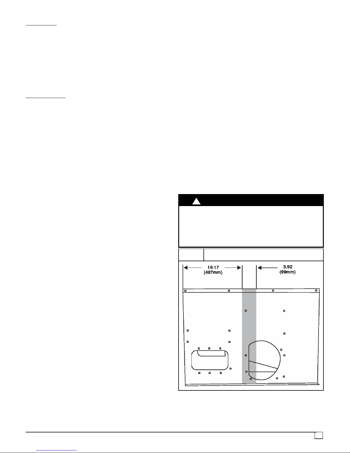
!
UNIT DAMAGE HAZARD
Failure to follow this caution may result in damage to unit
components.
When connecting ductwork to unit, do not drill deeper than
¾” (19mm) in shaded area shown in Figure 2 or coil may be
damaged.
FIGURE 2
Do Not Drill Shaded Area Deeper Than ¾” (19mm)
CAUTION
STEP 4 — Install Duct Connections
The design and installation of the duct system must be in
accordance with the standards of the NFPA for
installation of non--residence type air conditioning and
ventilating systems, NFPA 90A or residence type, NFPA
90B and/or local codes and ordinances.
Select and size ductwork, supply air registers, and return
air grilles according to ASHRAE (American Society of
Heating, Refrigeration, and Air Conditioning Engineers)
recommendations.
Use the duct flanges provided on the supply and return
openings on theside of the unit. See Figure 3 for connection
sizes and locations. The 14” (356mm) round duct collars
are shipped inside the unit attached to the base pan in the
indoor blower compartment. They are for field installation
and must be removed from the indoor blower compartment
prior to start--up, even if they are not used for installation.
3
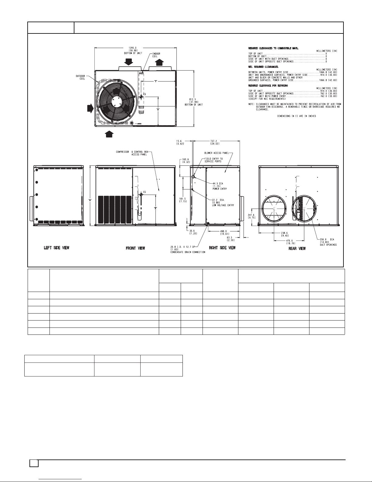
FIGURE 3
UNIT DIMENSIONS
Model
Size
24 208/230--1--60 268 121.6 30.13 [765] 14.0 [356] 19.0 [483] 15.0 [381]
30 208/230--1--60 299 135.6 34.13 [867] 14.0 [356] 19.0 [483] 16.0 [406]
36 208/230--1--60 352 159.7 42.13 [1070] 14.0 [356] 19.0 [483] 19.8 [503]
42 208/230--1--60 364 165.1 42.13 [1070] 14.0 [356] 19.0 [483] 21.9 [556]
48 208/230--1--60 359 162.8 42.13 [1070] 14.0 [356] 19.0 [483] 19.8 [503]
60 208/230--1--60 408 185.1 42.13 [1070] 14.0 [356] 19.0 [483] 21.9 [556]
ELECTRICAL
CHARACTERISTICS
UNIT WEIGHT
lbs kg X Y Z
UNIT
HEIGHT
in. [mm]
“A”
CENTER OF GRAVITY
inches [mm]
Table 1—Filter Data -- Throw--away Type
MODEL SIZE: 24, 30, 36 42, 48, 60
RETURN--AIR FILTER*
inches (mm)
24x24x1
(610x610x25)
30x30x1
(762x762x25)
* Required filter sizes shown are based on the larger of the
ARI (Air Conditioning and Refrigeration Institute) rated
cooling airflow or the heating airflow velocity of 300 feet per
minute for throwaway type or 450 feet per minute for
high--capacity type. Air filter pressure drop for
non--standard filters must not exceed 0.08 inches water
column.
4

STEP 5 — Connect Condensate Drain
NOTE: When installing condensate drain connection be
sure to comply with local codes and restrictions.
The packaged unit disposes of condensate water through
a w” NPT fitting which exits through the base on the
evaporator coil access side. See Figure 3 for location.
Condensate water can be drained directly onto the roof in
rooftop installations (where permitted) or onto a gravel
apron in ground level installations.Install a field--supplied 2”
(51mm) condensate trap at the end of condensate
connection to ensure proper drainage. Make sure that the
outlet of the trap is at least 1” (25mm) lower than the
drain--pan condensate connection to prevent the pan from
overflowing (see Figure 4). Prime the trap with water. When
using a gravel apron, make sure it slopes away from the
unit.
Connect a drain tube using a minimum of w” PVC or w”
copper pipe (all field--supplied) at the outlet end of the 2”
(51mm) trap. Do not undersize the tube. Pitch the draintube
downward at a slope of at least 1” (25mm). for every 10 feet
(3.0m) of horizontal run. Be sure to check the drain tube for
leaks.
FIGURE 4
Condensate Drain
!
UNIT COMPONENT DAMAGE HAZARD
Failure to follow this caution may result in damage to the
unit being installed.
1. Make all electrical connections in accordance with
NEC NFPA 70 (latest edition) and local electrical
codes governing such wiring. In Canada, all
electrical connections must be in accordance with
CSA standard C22.1 Canadian Electrical Code Part
1 and applicable local codes. Refer to unit wiring
diagram.
2. Use only copper conductor for connections between
field--supplied electrical disconnect switch and unit.
DO NOT USE ALUMINUM WIRE.
3. Be sure that high--voltage power to unit is within
operating voltage range indicated on unit rating
plate. Consult local power company for correction of
improper voltage and/or phase imbalance.
4. Insulate low--voltage wires for highest voltage
contained within conduit when low--voltage control
wires are in same conduit as high--voltage wires.
5. Do not damage internal components when drilling
through any panel to mount electrical hardware,
conduit, etc.
CAUTION
1” Min.
(25.4mm)
STEP 6 — Install Electrical Connections
!
ELECTRICAL SHOCK HAZARD
Failure to follow this warning could result in personal
injury or death.
The unit cabinet must have an uninterrupted, unbroken
electrical ground. This ground may consist of an
electrical wire connected to the unit ground screw in the
control compartment, or conduit approved for electrical
ground when installed in accordance with NEC, NFPA 70
National Fire Protection Association (latest edition) (in
Canada, Canadian Electrical Code CSA C22.1) and
local electrical codes.
WARNING
2” Min.
(51 mm)
High Voltage Connections
The unit must have a separate electrical service with a
field--supplied, waterproof disconnect switch mounted at, or
within sight from, the unit. Refer to the unit rating plate,NEC
and local codes for maximum fuse/circuit breaker size and
minimum circuit amps (ampacity) for wire sizing.
The field--supplied disconnect switch box may be mounted
on the unit over the high--voltage inlet hole when the
standard power and low--voltage entry points are used (see
Figure 3 and 5 for acceptable location).
When routing power leads into unit, use only copper wire
between disconnect and unit. The high voltage leads
should be in a conduit until they enter the duct panel;
conduit termination at the duct panel must be watertight.
See unit wiring label and Figures 10 -- 13 for reference when
making high voltage connections. Proceed as follows to
complete the high--voltage connections to the unit.
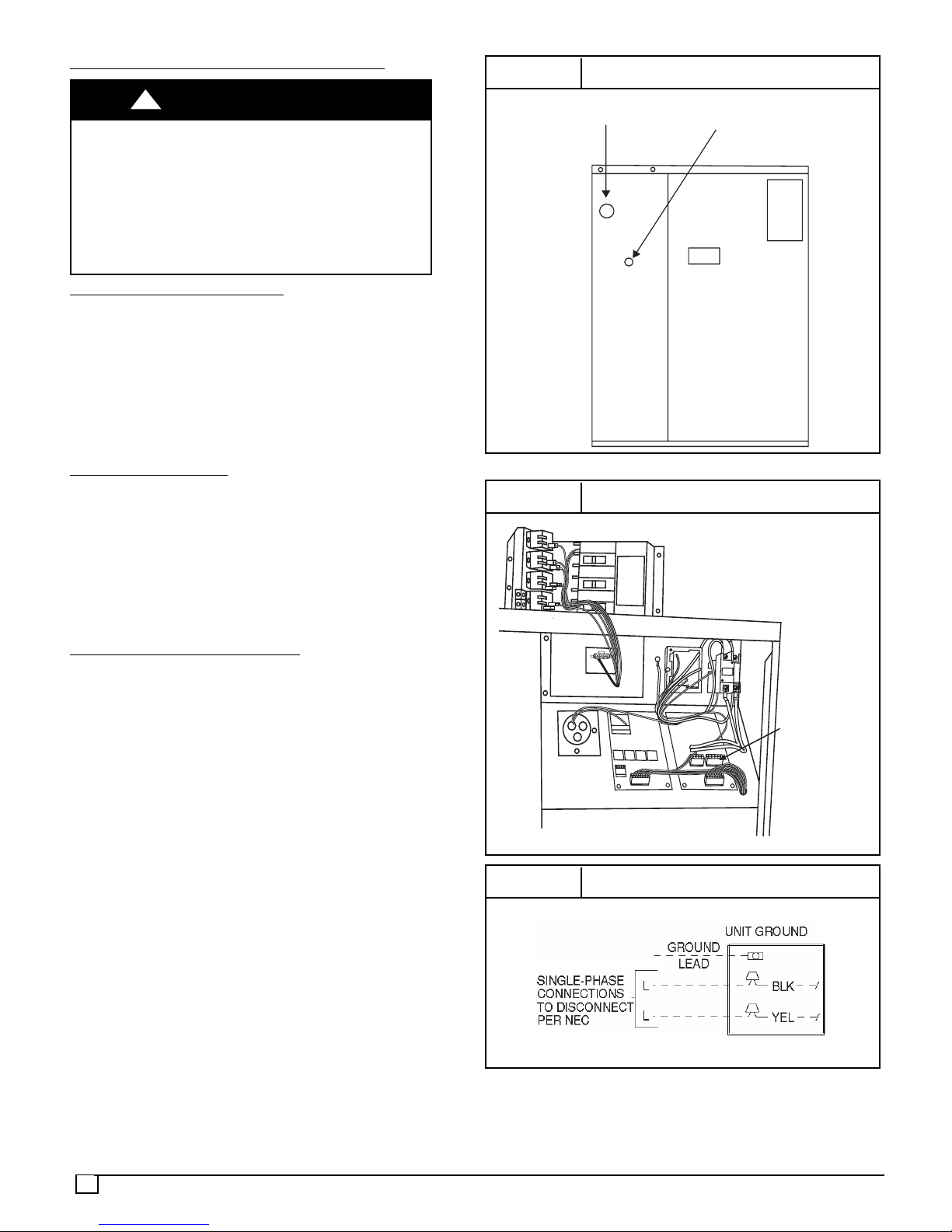
Single--phase units:
1. Run the high--voltage (L1, L2) and ground lead into the
control box.
2. Connect ground lead to chassis ground connection.
3. Locate the black and yellow wires connected to the line
side of the contactor.
4. Connect field L1 to black wire on connection 11 of the
compressor contactor.
5. Connect field wire L2 to yellow wire on connection 23 of
the compressor contactor.
5
Special Procedures For 208 Volt Operation
!
ELECTRICAL SHOCK HAZARD
Failure to follow this warning could result in personal
injury or death.
Before installing or servicing system, always turn off
main power to system. with disconnect switch open,
move black wire from transformer (x””) terminal marked
230 to terminal marked 208. This re--taps transformer to
primary voltage of 208 VAC.
WARNING
Control Voltage Connections
Do not use any type of power--stealing thermostat. Unit
control problems may result.
Use no. 18 American Wire Gage (AWG) color--coded,
insulated (35_C minimum) wires to make the control
voltage connections between the thermostat and the unit.
If the thermostat is located more than 100 feet from the unit
(as measured along the control voltage wires), use no. 16
AWG color--coded, insulated (35_C minimum) wires.
Standard
Connection
Form a drip--loop with the thermostat leads before routing
them into the unit. Route the thermostat leads through
grommeted hole provided in unit into unit control box (see
Figure 8). Connect thermostat leads and unit power leads
as shown in Figures 7, 8, and 9.
The unit transformer supplies 24 VAC power for the
complete system including accessory electrical heater.
Transformer is factory wired for 230 Volt operation.
Accessory Electric Heat W
iring
Refer to accessory electric heat installation instructions for
information on installingaccessory electric heat. Accessory
electric heat wiring is shown in Figure 12.
FIGURE 5
HIGH-VOLTAGE POWER
WIRING ENTRY HOLE
FIGURE 6
Electrical Entry Locations
LOW-VOLTAGE WIRING
ENTRY HOLE
Control Box Wiring
HEATER LOW
VOLTAGE PLUG
6
FIGURE 7
High Voltage (Line) Connections
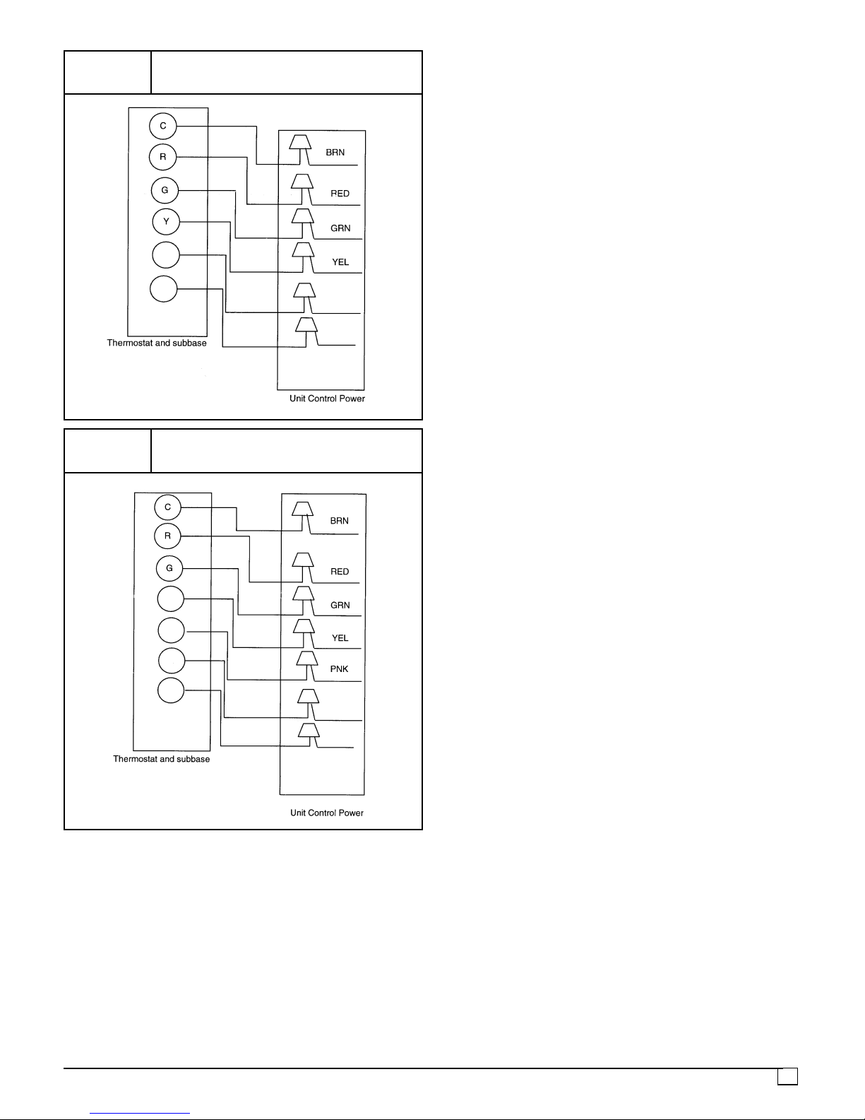
FIGURE 8
Low Voltage (Control) Connections,
Model Sizes 24, 30, 36, 42, 48
W2
FIGURE 9
W3
WHT
VIO
Low Voltage (Control) Connections,
Model Size 60
Y1
Y2
W2
W3
WHT
VIO
7

FIGURE 10 208/230 -- 1 -- 60 WIRING DIAGRAM, MODEL SIZES 24, 30, 36, 42, 48
8

FIGURE 11 208/230 -- 1 -- 60 WIRING DIAGRAM, MODEL SIZE 60
9

FIGURE 12 ACCESSORY ELECTRIC HEATER WIRING DIAGRAM
Single--Phase
10

PRE--STARTUP
!
WARNING
ENVIRONMENTAL, FIRE, EXPLOSION,
ELECTRICAL SHOCK HAZARD
Failure to follow this warning could result in personal
injury or death and/or property damage.
1. Follow recognized safety practices and wear
protective goggles when checking or servicing
refrigerant system.
2. Relieve and recover all refrigerant from system
before touching or disturbing anything inside
terminal box if refrigerant leak is suspected around
compressor terminals.
3. Never attempt to repair soldered connection while
refrigerant system is under pressure.
4. Do not use torch to remove any component.
System contains oil and refrigerant under
pressure.
5. To remove a component, wear protective goggles
and proceed as follows:
a. Shut off electrical power to unit and install
lockout tag.
b. Relieve and reclaim all refrigerant from
system using both high-- and low--pressure
ports.
c. Cut component connecting tubing with
tubing cutter and remove component from
unit.
d. Carefully unsweat remaining tubing stubs
when necessary. Oil can ignite when
exposed to torch flame.
Use the Start--Up Checklist supplied at the end of this book
and proceed as follows to inspect and prepare the unit for
initial start--up:
1. Remove all access panels.
2. Read and follow instructions on all DANGER,
WARNING, CAUTION, and INFORMATION labels
attached to, or shipped with unit.
3. Make the following inspections:
a. Inspect for shipping and handling damage, such as
broken lines, loose parts, disconnected wires, etc.
b. Inspect for oil at all refrigerant tubing connections
and on unit base. Detecting oil generally indicates
a refrigerant leak.
c. Leak--test all refrigerant tubing connections using
electronic leak detector, or liquid--soap solution. If
a refrigerant leak is detected, see following Check
for Refrigerant Leaks section.
d. Inspect all field-- and factory--wiring connections.
Be sure that connections are completed and tight.
e. Ensure wires do not touch refrigerant tubing or
sharp sheet metal edges.
f. Inspect coil fins. If damaged during shipping and
handling, carefully straighten fins with a fin comb.
4. Verify the following conditions:
a. Ensure fan hub is positioned correctly with respect
to motor housing.
b. Make sure that air filter(s) is in place.
c. Make sure that condensate drain trap is filled with
water to ensure proper drainage.
d. Make sure that all tools and miscellaneous loose
parts have been removed.
STARTUP
STEP 1 — Check for refrigerant leaks
Proceed as follows to locate and repair a refrigerant leak
and to charge the unit:
1. Locate leak and make sure that refrigerant system
pressure has been relieved and reclaimed from both
high-- and low--pressure ports.
2. Repair leak following accepted practices.
NOTE: Install a filter drier whenever the system has been
opened for repair.
3. Add a small charge of R--22 refrigerant vapor to system
and leak--test unit.
4. Recover refrigerant from refrigerant system and
evacuate to 500 microns if no additional leaks are
found.
5. Charge unit with R--22 refrigerant, using a volumetric
charging cylinder or accurate scale. Refer to unit rating
plate for required charge. Be sure to add extra
refrigerant to compensate for internal volume of filter
drier.
STEP 2 — Start--up cooling and make adjustments
Complete the required procedures given in the
Pre--Start--Up section before starting the unit. Do not
jumper any safety devices when operating the unit. Do not
operate the compressor when the outdoor temperature is
below 40° F(4.4° C). Do not rapid--cycle the compressor.
Allow 5 minutes between on cycles to prevent compressor
damage.
!
EXPLOSION AND ENVIRONMENTAL HAZARD
Failure to follow this warning could result in personal
injury, death or property damage.
System under pressure. Relieve pressure and recover
all refrigerant before system repair or final unit disposal.
Use all service ports and open all flow--control devices,
including solenoid valves.
WARNING
Check Cooling Control Operation
Start and check the unit for proper cooling control operation
as follows:
1. Place room thermostat SYSTEM switch in OFF
position. Observe that blower motor starts when FAN
switch is placed in ON position and shuts down when
FANswitchisplacedinAUTOposition.
2. Place SYSTEM switch in COOL position and FAN
switch in AUTO position. Set cooling control below
11

room temperature. Observe that compressor,
condenser fan, and evaporator blower motors start.
Observe that cooling cycle shuts down when control
setting is satisfied. The evaporator fan will continue to
run for 30 seconds.
Checking and Adjusting Refrigerant
The refrigerant system is fully charged with R--22
refrigerant and is tested and factory sealed.
NOTE:Adjustment of the refrigerant charge is not required
unless the unit is suspected of not having the proper R--22
charge.
An accurate thermocouple or thermistor type
thermometer and a gauge manifold are required when
using the subcooling charging method for evaluating the
unit charge. Do not use mercury or small dial--type
thermometers because they are not adequate for this
type of measurement.
NOTE: Allow system to operate a minimum of 15 minutes
before checking or adjusting charge.
Model Sizes 24, 30, 36, 42, and
Model Sizes 24, 30, 36, 42, and 48 have an orifice type
expansion device. Charge must be set using the
superheat method.
1. Remove cap from low--pressure service fittings.
2. Using hose with valve core depressor, attach
low--pressure gauge hose to low--pressure service
fitting.
3. Start unit in Cooling Mode and let unit run until
system pressures stabilize.
4. Measure and record the following:
a. Outdoor ambient--air temperature (dry bulb).
b. Suction (low--side) pressure (psig).
c. Suction line temperature.
5. Locate the measured suction line pressure in the top
row of Table 2 and the measured outdoor ambient
temperature in the left column of the table. Based on
the two values, determine the required suction line
temperature.
6. If the measured suction line temperature is greater
than the tabulated temperature, add charge to the
system. If the measured suction line temperature is
lower than the tabulated temperature, remove charge
from the system.
Model Size
Model Size 60 has a TXV expansion device. Charge
must be set using the subcooling method.
A subcooling charging chart is attached to the outside of
the service access panel. The chart includes the
required liquid line temperature at given discharge line
pressures and outdoor ambient temperatures.
Proceed as follows:
1. Remove cap from high and low--pressure service
fittings.
2. Using hoses with valve core depressors, attach high
and low--pressure gauge hose to high and
low--pressure service fittings.
3. Start unit in Cooling Mode and let unit run until system
pressures stabilize.
12
60:
Charge
48:
4. Measure and record the following:
a. Outdoor ambient--air temperature (dry bulb).
b. Liquid line temperature.
c. Discharge (high--side) pressure (psig).
d. Suction (low--side) pressure (psig) -- for reference
only.
5. Using “Sub--Cooling Charging Charts,” compare
outdoor--air temperature (dry bulb) with the discharge
line pressure (psig) to determine desired system
operating liquid line temperature (see Tables 3 and 4).
6. Compare actual liquid line temperature with desired
liquid line temperature. Using a tolerance of +/-- 2° F
(+/-- 1.1° C), add refrigerant if actual temperature is
higher than proper liquid line temperature, or remove
refrigerant if actual temperature is lower than desired
liquid line temperature.
!
UNIT DAMAGE HAZARD
Failure to follow this caution may result in unit
damage.
When evaluating the refrigerant charge, an indicated
adjustment to the specified factory charge must
always be very minimal. If a substantial adjustment is
indicated, an abnormal condition exists somewhere in
the cooling system, such as insufficient airflow across
either coil or both coils.
NOTE: If the problem causing the inaccurate readings is a
refrigerant leak, refer to the Check for Refrigerant Leaks
section.
CAUTION

Table 2 -- Superheat Method, Sizes 24, 30 ,36, 42, and 48
Outdoor
Temperature
(°F)
45 51 55 60 64 69 — — — — — — — — — —
55 — — 53 57 62 66 70 — — — — — — — —
65 — — — — 53 57 62 66 71 75 — — — — —
75 — — — — — — — 56 61 66 71 76 — — —
85 — — — — — — — — 53 58 63 67 72 — —
95 — — — — — — — — — 50 54 58 62 66 —
105 — — — — — — — — — — 50 53 57 60 64
115 — — — — — — — — — — 49 52 55 58 61
125 — — — — — — — — — — — 50 53 56 59
Outdoor
Temperature
(°C)
7 11 13 15 18 21 — — — — — — — — — —
13 — — 12 14 16 19 21 — — — — — — — —
18 — — — — 12 14 17 19 21 24 — — — — —
24 — — — — — — — 13 16 19 22 24 — — —
29 — — — — — — — — 12 14 17 20 22 — —
35 — — — — — — — — — 10 12 14 17 19 —
41 — — — — — — — — — — 10 12 14 16 18
46 — — — — — — — — — — 9 11 13 14 16
52 — — — — — — — — — — — 10 11 13 15
52 54 56 59 61 64 67 70 73 76 79 82 85 89 92
361 370 387 405 423 442 462 482 502 523 544 566 589 612 636
Measured Suction Line Pressure (PSIG)
REQUIRED SUCTION LINE TEMPERATURE (°F)
Measured Suction Line Pressure (kPa)
REQUIRED SUCTION LINE TEMPERATURE (°C)
13
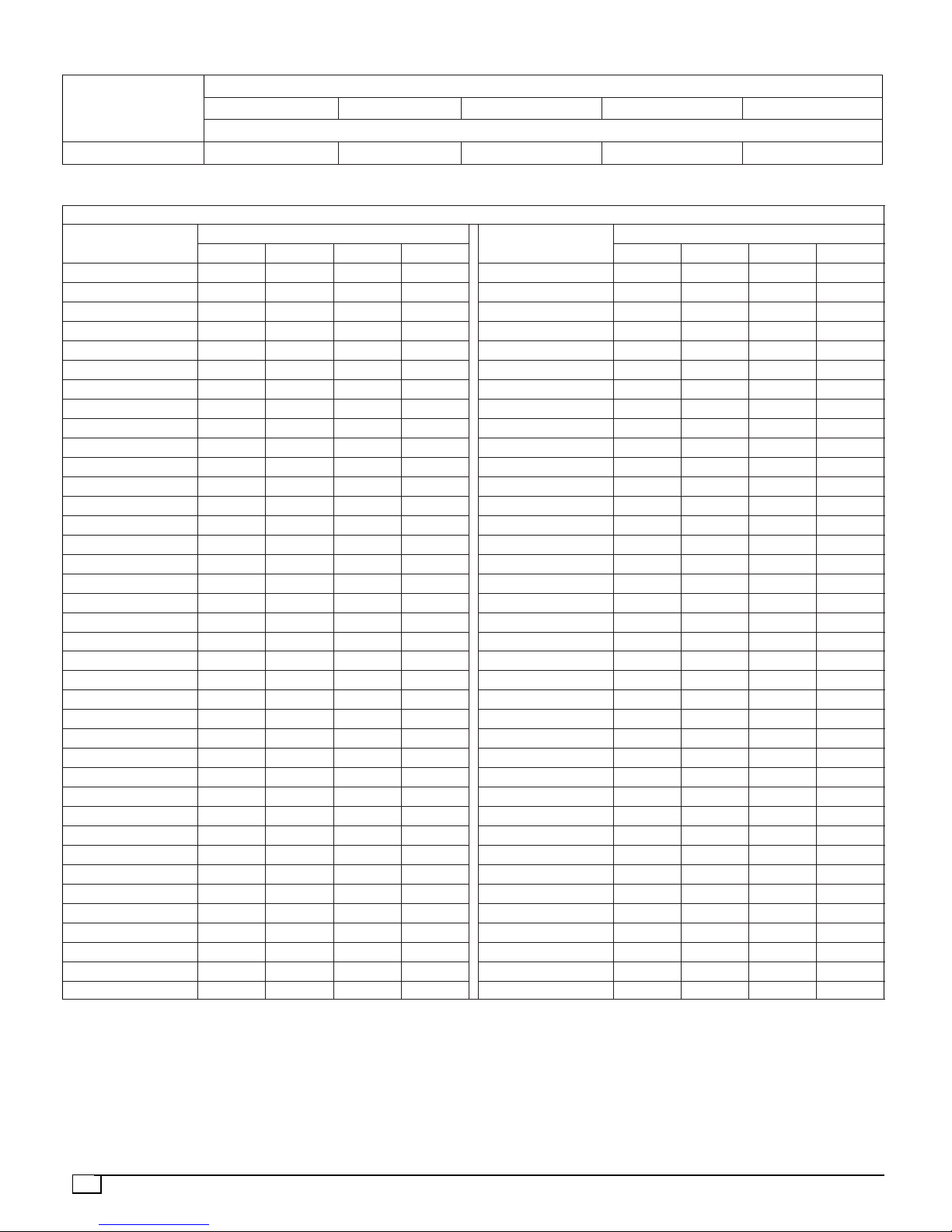
Table 3 -- Subcooling Method, Size 60
Outdoor Ambient Temperature °F(°C)
Model Size
75 (24) 82 (28) 85 (29) 95 (35) 105 (41)
REQUIRED SUBCOOLING °F(°C)
60 21 (11.7) 20.5 (11.4) 20 (11.1) 19 (10.6) 16 (8.9)
Table 4 -- Required Liquid Line Temperature
REQUIRED LIQUID LINE TEMPERATURE FOR A SPECIFIC SUBCOOLING (R-- 22)
Pressure (psi)
134 71 66 61 56 924 24 22 19 16
141 74 69 64 59 972 26 23 21 18
156 80 75 70 65 1075 30 27 24 21
163 83 78 73 68 1124 31 28 26 23
170 86 81 76 71 1172 33 30 27 24
177 89 84 79 74 1220 34 31 29 26
184 91 86 81 76 1268 36 33 30 27
191 94 89 84 79 1317 37 34 31 29
198 96 91 86 81 1365 38 36 33 30
205 98 93 88 83 1413 40 37 34 31
213 101 96 91 86 1468 41 38 36 33
221 104 99 94 89 1524 43 40 37 34
229 106 101 96 91 1579 44 41 38 36
237 108 103 98 93 1634 45 42 40 37
245 111 106 101 96 1689 47 44 41 38
253 113 108 103 98 1744 48 45 42 40
262 116 111 106 101 1806 49 46 44 41
271 118 113 108 103 1868 51 48 45 42
280 121 11 6 111 106 1930 52 49 46 44
289 123 11 8 11 3 108 1992 53 51 48 45
298 125 120 115 110 2054 55 52 49 46
307 128 123 118 113 2116 56 53 50 48
317 130 125 120 115 2185 57 54 52 49
327 132 127 122 117 2254 59 56 53 50
337 135 130 125 120 2323 60 57 54 52
347 137 132 127 122 2392 61 58 56 53
357 139 134 129 124 2461 62 60 57 54
367 142 137 132 127 2530 64 61 58 55
Required Subcooling (°F)
5 10 15 20 3 6 8 11
Pressure (kPa)
Required Subcooling (°C)
14

Indoor Airflow and Airflow Adjustments
NOTE: For cooling operation, the recommended airflow
is 350 to 450 CFM for each 12,000 BTU/h of rated
cooling capacity.
Table 6 shows cooling airflows at various external static
pressures. Refer tothis table to determine theairflow for the
system being installed.
NOTE: Be sure that all supply and return--air grilles are
open, free from obstructions, and adjusted properly.
!
WARNING
ELECTRICAL SHOCK HAZARD
Failure to follow this warning could result in personal
injury or death.
Disconnect electrical power to the unit and install
lockout tag before changing blower speed.
Airflow can be changed by changing the lead connections
at the blower motor. To change motor speeds, reposition
wire at fan motor speed terminals labeled 1--2--3--4 (refer to
Figure 13).
Remove the speed tap connector labeled 1through 5 on the
motor. While looking at the connector end that is inserted
into the motor, gently pry the locking tab outward and
remove the wire from the connector. Insert the wire into the
desired tap until it locks into place. Be sure new airflow
meets the range noted above and minimum electric heat
CFM, if equipped. Refer to table 6 and table 10.
All model sizes are factory wired for rated airflow operation.
Figure 13
1234
Motor Speed Selection
STEP 3 — Unit Controls
All units have the following factory installed or
internal--protection controls.
Compressor High Pressure Relief V
This internal valve opens when the pressure differential
between the low and high side becomes excessive.
Loss of Charge
Located on the outdoor liquid line is a low--pressure switch
which functions as a loss--of--charge switch. This switch
contains a Schrader core depressor. This switch opens at
7 psig and closes at 22 psig. No adjustment is necessary.
Compressor
This internal overload interrupts power to the compressor
when either the current or internal temperature become
excessive, and automatically resets when the internal
temperature drops to a safe level.
This overload may require up to 60 minutes (or longer) to
reset. If the internal overload is suspected of being open,
disconnect the electrical power to the unit and check the
circuit through the overload with an ohmmeter or continuity
tester.
STEP 4 — Sequence of Operation
Operation
Fan
The FAN switch on the thermostat controls indoor fan
operation. When the FAN switch is placed in the ON
position, the IFR (indoor--fan relay) is energizedthrough the
G terminal on the thermostat. The normally--open contacts
close, which then provide power to the indoor (evaporator)
fan motor (IFM). The IFM will run continuously when the
FAN switch is set to ON.
When the FAN switch is set to AUTO, the thermostat
energizes the IFR only when there is a call for cooling or, if
the unit is equipped with accessory electric heat, the
indoor--fan motor will also run while the accessory electric
heat is energized.
NOTE: Some units are equipped with a time--delay relay.
On these units, the indoor fan remains on for 30 seconds
after G or Y is de--energized.
Switch
Overload
alve
Table 5 -- Motor Speed Taps
SIZE
24 Ta p 1 Ta p 3
30 Ta p 2 Ta p 4
36 Ta p 1 Ta p 3
42 Ta p 2 Ta p 4
48 Ta p 3 Ta p 4
SIZE
60 Ta p 1 Ta p 3 Ta p 2 Ta p 4
RATED AIRFLOW HIGH AIRFLOW
RATED AIRFLOW HIGH AIRFLOW
Low
Stage
High
Stage
Low
Stage
High
Stage
Cooling Operation (model sizes 24, 30, 36, 42,
With a call for cooling (Y/Y2), the indoor fan and contactor
energize immediately, starting the compressor and the
outdoor fan motor. When the cooling demand is met, Y/Y2
de--energizes, shutting off the compressor, indoor fan, and
the outdoor fan.
Cooling Operation (model size
This unit requires a 2--stage indoor thermostat. With a first
(low) stage call for cooling (Y1), the indoor fan (low stage
speed) and contactor energize immediately, starting the
compressor (low stage) and the outdoor fan motor. If the
first (low) stage operation cannot satisfy the cooling
demand, the second (high) stage cooling (Y2) energizes.
The compressor is switched into high stage cooling
(internal solenoid valve inside the compressor) and the
indoor fan switches to high stage speed. When second
stage cooling is satisfied, Y2 de--energizes switching the
60)
48)
15
compressor and indoor fan back to low stage
cooling/speed. When the low stage cooling demand is met,
Y1 de--energizes, shutting off the compressor, indoor fan,
and outdoor fan.
Continuous Fan
With the continuous Indoor fan option selected on the
thermostat, G is continuously energized. For model sizes
24, 30, 36, 42 and 48 the selected airflow setting is
provided. For model size 60, the systemruns low stage (Y1)
airflow for continuous fan operation.
MAINTENANCE
!
PERSONAL INJURY AND UNIT DAMAGE HAZARD
Failure to follow this warning could result in personal
injury or death and unit component damage.
The ability to properly perform maintenance on this
equipment requires certain expertise, mechanical skills,
tools and equipment. If you do not possess these, do not
attempt to perform any maintenance on this equipment,
other than those procedures recommended in the
Owner’s Manual.
To ensure continuing high performance and to minimize the
possibility of premature equipment failure, periodic
maintenance must be performed on this equipment. This
unit should be inspected at least once each year by a
qualified service person. To troubleshoot unit, refer to Table
11 -- Troubleshooting Guide.
NOTE TO EQUIPMENT OWNER: Consult your local dealer
about the availability of a maintenance contract.
!
ELECTRICAL SHOCK HAZARD
Failure to follow these warnings could result in personal
injury or death:
1. Turn off electrical power to the unit beforeperforming
any maintenance or service on this unit. Install lockout tag.
2. Use extreme caution when removing panels and
parts.
3. Never place anything combustible either on or in
contact with the unit.
UNIT OPERATION HAZARD
Failure to follow this caution may result in improper
operation.
Errors made when reconnecting wires may cause
improper and dangerous operation. Label all wires prior
to disconnecting when servicing.
WARNING
WARNING
!
CAUTION
Electric Resistance Heating
Electric heaters are available as accessories and must be
field installed. On a call for “Emergency Heat” the
thermostat energizes W which energizes the heater relay
and in turn energizes the electric heaters. The IFR is
energized which starts the indoor--fan motor. If the heaters
are staged, W2 is energized when the second stage of
heating is required. When the need for heating is satisfied,
the heater and IFM are de--energized.
The minimum maintenance requirements for this
equipment are as follows:
1. Inspect air filter(s) each month. Clean or replace when
necessary.
2. Inspect indoor coil, drain pan, and condensate drain
each cooling season for cleanliness. Clean when
necessary.
3. Inspect blower motor and wheel for cleanliness at the
beginning of each cooling season. Clean when
necessary.
4. Check electrical connections for tightness and controls
for proper operation each cooling season. Service
when necessary.
5. Ensure electric wires are not in contact with refrigerant
tubing or sharp metal edges.
Air
Filter
NOTE: Never operate the unit without a suitable air filter in
the return--air duct system. Always replace the filter with the
same dimensional size and type as originally installed. See
Table 1 for recommended filter sizes.
Inspect air filter(s) at least once each month and replace
(throwaway--type) or clean (cleanable--type) at least twice
during each cooling season or whenever the filter becomes
clogged with dust and lint.
Unit Top Removal (Outdoor--Coil
NOTE: When performing maintenance or service
procedures that require removal of the unit top, be sure to
perform all of the routine maintenance procedures that
require top removal, including coil inspection and cleaning,
and condensate drain pan inspection and cleaning.
Only qualified service personnel should perform
maintenance and service procedures that require unit top
removal.
Refer to the following top removal procedures:
1. Remove screws on unit top cover surface. (Save all
screws.)
2. Remove screws on unit top cover flange. (Save all
screws.)
3. Lift top from unit carefully. Set top on edge and make
sure that top is supported by unit side that is opposite
duct (or plenum) side.
4. Carefully replace and secure unit top to unit, using
screws removed in Steps 1 and 2, when maintenance
and/or service procedures are completed.
Side)
16

Indoor Motor and Blower
NOTE: All motors are pre--lubricated. Do not attempt to
lubricate these motors.
For longer life, operating economy, and continuing
efficiency, clean accumulated dirt and grease from the
blower wheel and motor annually.
!
ELECTRICAL SHOCK HAZARD
Failure to follow this warning could result in personal
injury or death.
Disconnect and tag electrical power to the unit before
cleaning and lubricating the blower motor and wheel.
To clean the blower motor and wheel:
1. Remove the blower housing:
a. Remove the screws on the external side of the duct
panel that fasten the housing to the duct panel
assembly.
b. Remove the side access panel and unscrew the
mounting bracket that fastens the blower housing
to the internal partition panel fo the control box
assembly.
c. Make sure that the blower housing is supported by
hand before completely removing the mounting
bracket.
d. Slide the blower housing from the rails of the duct
panel and place it outside the unit.
2. Remove the blower wheel from the housing:
a. Loosen the set screw which secures the wheel to
the motor shaft.
b. Loosen the three mounting legs of the motor by
removing the bolts that fasten themounting legs to
the housing.
c. Slide out the motor assembly (motor, belly band
and the 3 mounting legs) from the hub of the wheel.
d. Remove the filler panel at the discharge end of the
blower housing by removing the two screws that
fasten it to the housing.
e. Remove the wheel form the housing.
3. Remove the cakedon dirt from the wheel and themotor
usingabrush.
4. Remove lint and dirt accumulations from the wheel and
housing with a vacuum cleaner, using a soft brush
attachment.
5. Remove grease and oil with a mild solvent.
6. Reassemble
a. Slip the wheel back in the housing with the hub set
screw parented in the correct direction.
b. Install the filler panel.
c. Reinsert the motor assembly in the wheel hub and
align the mounting legs with the housing mounting
hold locations.
d. Tighten the mounting bolts to fasten the motor
assembly with the housing.
e. Center the wheel in the housing by sliding it, align
the flat end of the shaft with the set screw and
tighten the set screw.
WARNING
f. Slide back the blower housing into the mounting
rails in the duct panel and install the mounting
bracket back in its position.
g. Install the screws on the external side of the duct
panel to fasten duct panel with the housing.
h. Replace the side access panel.
Outdoor Coil, Indoor Coil, and Condensate Drain
Inspect the condenser coil, evaporator coil, and
condensate drain pan at least once each year.
The coils are easily cleaned when dry; therefore, inspect
and clean the coils either before or after each cooling
season. Remove all obstructions, including weeds and
shrubs, that interfere with theairflow through the condenser
coil.
Straighten bent fins with a fin comb. Ifcoated with dirt or lint,
clean the coils with a vacuum cleaner, using the soft brush
attachment. Be careful not to bend the fins. If coated with oil
or grease, clean the coils with a mild detergent and water
solution. Rinse coils with clear water, using a garden hose.
Be careful not to splash water on motors, insulation, wiring,
or air filter(s). For best results, spray condenser coil fins
from inside to outside the unit. On units with an outer and
inner condenser coil, be sure toclean between the coils. Be
sure to flush all dirt and debris from the unit base.
Inspect the drain pan and condensate drain line when
inspecting the coils. Clean the drain pan and condensate
drain by removing all foreign matter from the pan. Flush the
pan and drain trough with clear water. Do not splash water
on the insulation, motor, wiring, or air filter(s). If the drain
trough is restricted, clear it with a “plumbers snake” or
similar probe device.
Outdoor
1. Remove 6 screws holding discharge grille and motor to
2. Turn motor/grille assembly upside down on top cover to
3. Inspect the fan blades for cracks or bends.
4. If fan needs to be removed, loosen setscrew and slide
5. When replacing fan blade, position blade so that the
6. Ensure that setscrew engages the flat area on the
7. Replace grille.
Fan
!
CAUTION
UNIT OPERATION HAZARD
Failure to follow this caution may result in damage to
unit components.
Keep the condenser fan free from all obstructions to
ensure proper cooling operation. Never place articles
on top of the unit.
top cover.
expose fan blade.
fan off motor shaft.
hub is 8” (3.2mm) away from the motorend (8” (3.2mm)
of motor shaft will be visible).
motor shaft when tightening.
Pan
17

Electrical Controls and Wiring
Inspect and check the electrical controls and wiring
annually. Be sure to turn off the electrical power to the unit.
Remove access panel to locate all the electrical controls
and wiring. Check all electrical connections for tightness.
Tighten all screw connections. If any smoky or burned
connections are noticed, disassemble the connection,
clean all theparts, re--strip the wire end and reassemblethe
connection properly and securely.
After inspecting the electrical controls and wiring, replace all
the panels. Start the unit, and observe at least one complete
cooling cycle to ensure proper operation. If discrepancies
are observed in operating cycle, or if a suspected
malfunction has occurred, check each electrical component
with the proper electrical instrumentation. Refer to the unit
wiring label when making these checks.
NOTE: Refer to the Cooling Sequence of Operation in this
document to understand proper control operation.
Refrigeration
Annually inspect all refrigerant tubing connections and
the unit base for oil accumulations. Detecting oil generally
indicates a refrigerant leak.
If oil is detected or if low cooling performance is
suspected, leak--test all refrigerant tubing using an
electronic leak--detector, halide torch, or liquid--soap
solution. If a refrigerant leak is detected, refer to the
Check for Refrigerant Leaks section.
If no refrigerant leaks are found and low cooling
performance is suspected, refer to the Checking and
Adjusting Refrigerant Charge section.
Circuit
Evaporator Airflow
The heating and/or cooling airflow does not require
checking unless improper performance is suspected. If a
problem exists, be sure that all supply-- and return--air
grilles are open and free from obstructions, and that the
air filter is clean. When necessary, refer to the Indoor
Airflow and Airflow Adjustments section to check the
system airflow.
Metering
Model sizes 24, 30, 36, and 42 use an orifice type
metering device.
Model sizes 48 and 60 use a hard shutoff, balance port
TXV. The TXV maintains a constant superheat at the
evaporator exit.
Liquid Line
The liquid line strainers (to protect metering devices) are
made of wire mesh and are located in the liquid lines on the
inlet side of the metering devices.
High Flow V
High flow valvesare located onthe compressor hot gas and
suction tubes. Large black plastic caps distinguish these
valves from the smaller service valves. These valves can
not be accessed for service in the field. Ensure the plastic
caps are in place and tight or the possibility of refrigerant
leakage could occur.
Devices
Strainers
alves
!
EXPLOSION, SAFETY AND ENVIRONMENTAL
HAZARD
Failure to follow this warning could result in personal
injury, death or property damage.
System under pressure. Relieve pressure and recover all
refrigerant before system repair or final unit disposal. Use
all service ports and open all flow--control devices,
including solenoid valves.
WARNING
TROUBLESHOOTING
Use the Troubleshooting Guide (see Table 11) if problems occur with these units.
STARTUP CHECKLIST
Use Start--Up checklist to ensure proper start--up procedures are followed.
18
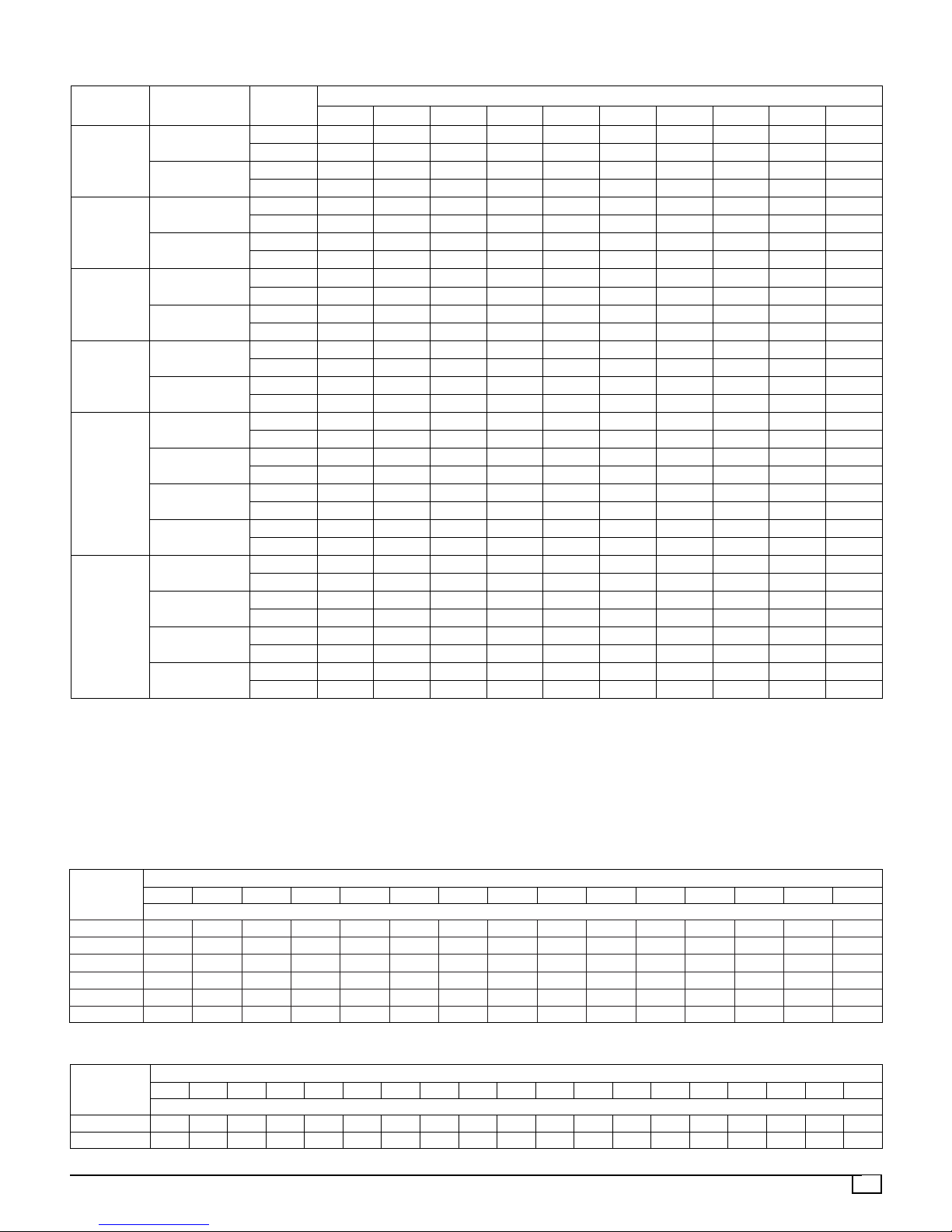
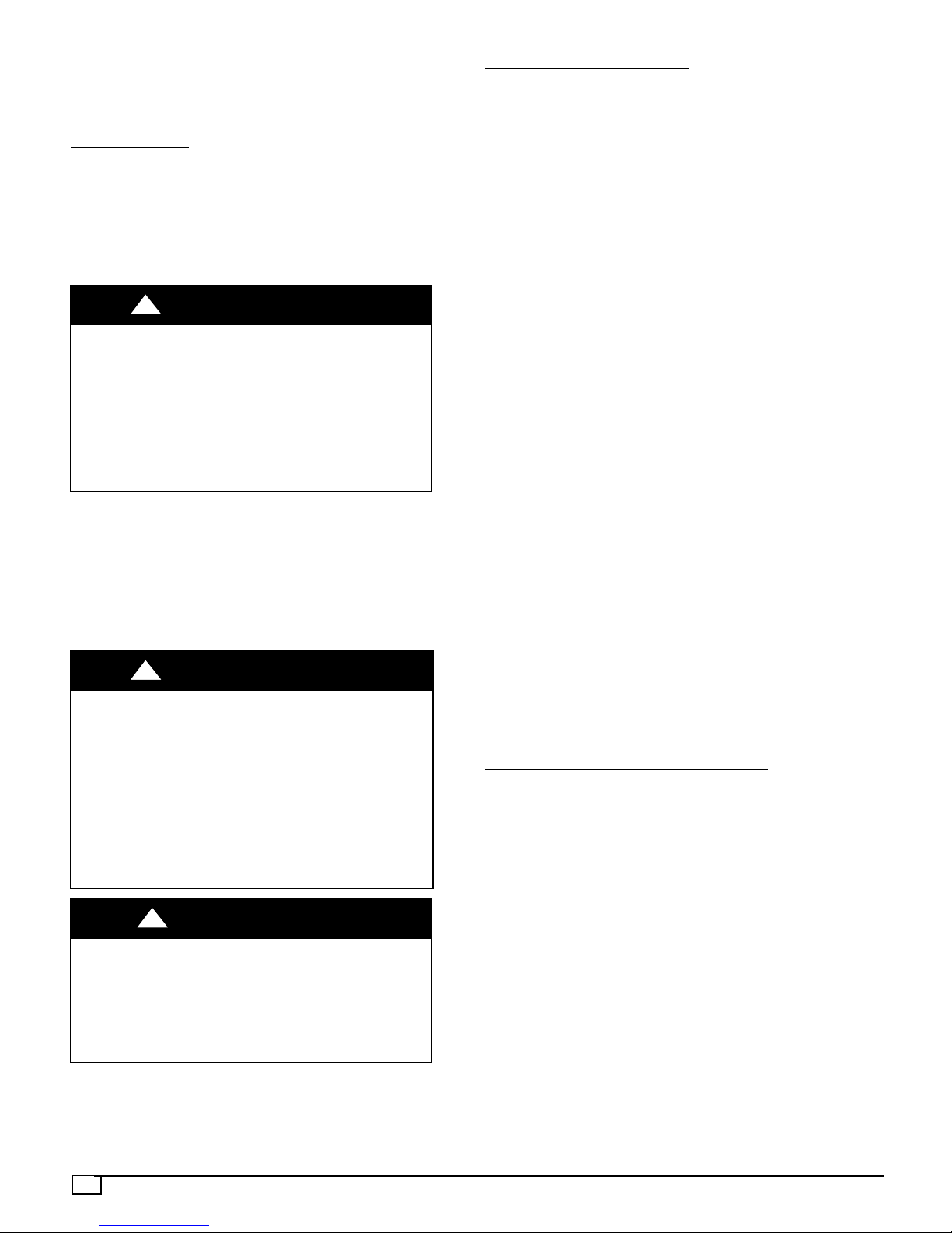
Table 6 -- Dry Coil Air Delivery*
Model
Size
24
30
36
42
48
60
Motor
Speed Tap
1
2
2
3
1
2
3
4
1
2
3
4
1
2
3
4
External Static Pressure (Inches Water Column)
0.1 0.2 0.3 0.4 0.5 0.6 0.7 0.8 0.9 1.0
Watts — 99 100 118 130 142 — — — —
CFM — 848 793 757 698 632 — — — —
Watts — — — — — 222 233 244 257 260
CFM — — — — — 970 918 861 795 729
Watts — 155 146 157 170 — — — — —
CFM — 1108 995 951 884 — — — — —
Watts — — — — — 261 275 286 291 315
CFM — — — — — 1117 1053 1014 980 877
Watts 180 166 179 191 204 216 — — — —
CFM 1344 1215 1172 1136 1095 1051 — — — —
Watts — — — 261 276 290 301 316 329 342
CFM — — — 1343 1304 1272 1234 1190 1148 1100
Watts 269 283 305 321 336 349 360 — — —
CFM 1440 1404 1369 1333 1301 1273 1239 — — —
Watts — — 418 432 450 465 480 490 503 518
CFM — — 1572 1543 1504 1475 1441 1418 1380 1332
Watts — 204 209 216 229 236 249 — — —
CFM — 1129 1087 1027 994 932 881 — — —
Watts — — 233 245 254 266 276 289 — —
CFM — — 1164 1122 1066 1025 954 906 — —
Watts 386 398 409 418 425 435 438 441 451 —
CFM 1680 1652 1625 1583 1555 1515 1477 1444 1403 —
Watts — 440 448 457 462 469 477 480 485 486
CFM — 1745 1717 1684 1651 1612 1573 1537 1508 1470
Watts 224 235 251 266 277 291 298 — — —
CFM 1334 1288 1259 1224 1181 1157 1117 — — —
Watts — — 286 301 311 325 333 344 370 —
CFM — — 1333 1296 1261 1232 1199 1170 1062 —
Watts 608 626 643 660 668 685 697 — — —
CFM 1931 1900 1878 1844 1817 1789 1755 — — —
Watts 737 755 770 787 799 817 826 812 782 —
CFM 2093 2061 2028 2001 1971 1934 1899 1850 1757 —
* Air delivery values are without air filter and are for dry coil (See Wet Coil Pressure Drop table). Deduct
field--supplied air filter pressure drop and wet coil pressure drop to obtain external static pressure available for
ducting.
Notes:
1. Do not operate the unit at a cooling airflow that is less than 350 cfm for each 12,000 Btuh of rated cooling capacity.
Evaporator coil frosting may occur at airflows below this point.
2. Dashes indicate portions of table that are beyond the blower motor capacity or are not recommended.
Table 7 -- Wet Coil Pressure Drop
STANDARD CFM (S.C.F.M.)
MODEL
SIZE
24 .027 .034 040 .047 .053 -- -- -- -- -- -- -- -- -- -30 -- .036 .042 .050 .055 .063 .072 .081 -- -- -- -- -- -- -36 -- -- -- .050 .055 .063 .072 .081 .090 .097 -- -- -- -- -42 -- -- -- -- .042 .049 .052 .059 .065 .071 .078 .085 .091 -- -48 -- -- -- -- -- -- .072 .081 .090 .097 .108 .120 .129 .139 -60 -- -- -- -- -- -- -- -- -- .071 .078 .085 .091 .098 .114
600 700 800 900 1000 1100 1200 1300 1400 1500 1600 1700 1800 1900 2000
Pressure Drop (inches water column)
Table 8 -- Filter Pressure Drop Table
CFM
500 600 700 800 900 1000 1100 1200 1300 1400 1500 1600 1700 1800 1900 2000 2100 2200 2300
FILTER SIZE
24x24x1 0.06 0.07 0.08 0.08 0.09 0.09 0.09 0.10 0.11 0.12 0.14 0.15 — — — — — — —
30x30x1 — — — — — — — — 0.08 0.09 0.10 0.11 0.12 0.13 0.14 0.15 0.16 0.17 0.18
Pressure Drop (inches water column)
19

Table 9 -- Accessory Electric Heater Pressure Drop Table
CFM
HEATER kW
600 800 1000 1200 1400 1600 1800 2000 2200
Pressure Drop (inches water column)
5--20 0.06 0.08 0.10 0.13 0.15 0.18 0.20 0.23 0.25
Table 10 -- Minimum Airflow for Safe Electric Heater Operation
Unit Size
5kW 7.5 kW 10 kW 15 kW 20 kW
Minimum Airflow (CFM)
24 400 550 650 -- -- -- -- -- --
30 450 600 800 850 -- -- --
36 450 600 800 850 900
42 450 600 800 850 900
48 450 600 800 850 900
60 450 600 800 850 900
20

SYMPTOM CAUSE REMEDY
Compressor and condenser
fan will not start.
Compressor will not start
but condenser fan runs
Compressor cycles (other
than normally satisfying
thermostat)
Compressor operates
continuously
Excessive head pressure
Head pressure too low
Excessive suction pressure
Suction pressure too low
Table 11 -- Troubleshooting Guide
Power failure Call power company
Fuse blown or circuit breaker tripped Replace fuse or reset circuit breaker
Defective contactor, transformer, or high--pres-
sure, loss--of--charge or low--pressure switch
Insufficient line voltage Determine cause and correct
Incorrect or faulty wiring Check wiring diagram and rewire correctly
Thermostat setting too high
Faulty wiring or loose connections in compressor circuit
Compressor motor burned out, seized, or Determine cause
internal overload open Replace compressor
Defective run/start capacitor, overload, start
relay
Low input voltage Determine cause and correct
Refrigerant overcharge or undercharge
Defective compressor Replace and determine cause
Insufficient line voltage Determine cause and correct
Blocked outdoor coil Determine cause and correct
Defective run/start capacitor Determine cause and replace
Faulty outdoor fan motor or capacitor Replace
Restriction in refrigerant system Locate restriction and remove
Dirty air filter Replace filter
Unit undersized for load Decrease load or increase unit size
Thermostat temperature set too low Reset Thermostat
Low refrigerant charge Locate leak, repair, and recharge
Air in system
Outdoor coil dirty or restricted Clean coil or remove restriction
Dirty air filter Replace filter
Dirty condenser coil Clean coil
Refrigerant overcharged Recover excess refrigerant
Air in system
Condenser air restricted or air short--cycling Determine cause and correct
Low refrigerant charge Check for leaks, repair, and recharge.
Restriction in liquid tube Remove restriction
High heat load Check for source and eliminate
Compressor valves leaking Replace compressor
Refrigerant overcharged Recover excess refrigerant
Dirty air filter Replace filter
Low refrigerant charge Check for leaks, repair and recharge
Metering device or low side restricted Remove source of restriction
Insufficient evaporator airflow
Temperature too low in conditioned area Reset Thermostat
Outdoor ambient below 55°F (12.7°C) Install low--ambient kit
Filter drier restricted Replace filter
Replace component
Lower Thermostat temperature setting below
room temperature
Check wiring and repair or replace
Determine cause and replace
Recover refrigerant, evacuate system, and
recharge to capacities shown on rating plate
Recover refrigerant, evacuate system, and
recharge
Recover refrigerant, evacuate system, and
recharge
Increase air quantity
Check filter–replace if necessary
21

START--UP CHECKLIST
(Remove and Store in Job File)
1. Preliminary Information
Model Number:
Serial Number:
Date:
Technician:
2. Pre--Start--Up
____ Verify that all packing materials have been removed from unit
____ Check all electrical connections and terminals for tightness
____ Check that the indoor (evaporator) air filter is clean and in place
____ Verify that the unit installation is level
____ Check blower (indoor) and propeller (outdoor) for location in housing/orifice (no rubs) and set screw tightness
3. Start--Up
Electrical
Supply Voltage (measured):
Compressor Amps (measured):
Indoor (evaporator) motor amps:
Temperatures
Outdoor (condenser) air temperature (dry bulb):
Indoor return air temperature: (dry bulb) (wet bulb):
Indoor supply air -- cooling: (dry bulb) (wet bulb):
Pressures
Refrigerant suction pressure during cooling (psi):
Refrigerant discharge pressure during cooling (psi):
____ Verify proper refrigerant charge using charging chart
22
 Loading...