

International comfort products PAN324, PAN330, PAN336, PAN342, PAN348 Installation Instructions Manual
...
Installation Instructions
PAN3 Series
Single Phase
PACKAGED AIR CONDITIONERS
TABLE OF CONTENTS
Page
SAFE INSTALLATION REQUIREMENTS 2........
INTRODUCTION 2.............................
RECEIVING AND INSTALLATION 2...............
Check Equipment 2.............................
Provide Unit Support 2..........................
Provide Clearances 3...........................
Field Fabricate Ductwork 3.......................
Rig and Place Unit 3 -- 4.........................
Dimensions 5 -- 6...............................
Filter Data and Corner Weights 7.................
Connect Condensate Drain 8.....................
Install Duct Connections 8.......................
Install Electrical Connections 9 --10...............
PRE--START--UP 11............................
START--UP 11..................................
Check for Refrigerant Leaks 1 1...................
Start--Up Adjustments 11........................
Wiring Diagrams 12.............................
Checking and Adjusting Refrigerant Charge 13.....
Indoor Airflow and Airflow Adjustment 13...........
Cooling Sequence of Operation 13................
Cooling Charging Chart 14.......................
Wet Coil Air Delivery 14..........................
MAINTENANCE 15.............................
Air Filter 16....................................
Indoor Blower and Motor 16......................
Outdoor & Indoor Coil, & Condensate Drain Pan 16.
Outdoor Fan 16.................................
Electrical Controls and Wiring 17..................
Indoor Airflow 17................................
Metering Devices--Fixed Orifice 17................
TROUBLESHOOTING 18........................
START--UP CHECKLIST 19......................
Printed in U.S.A.
International Comfort Products, LLC
Lewisburg, TN. 37091
519 01 1701 01 01--28--08
SAFE INSTALLATION REQUIREMENTS
We require these instructions as a minimum for a safe
installation.
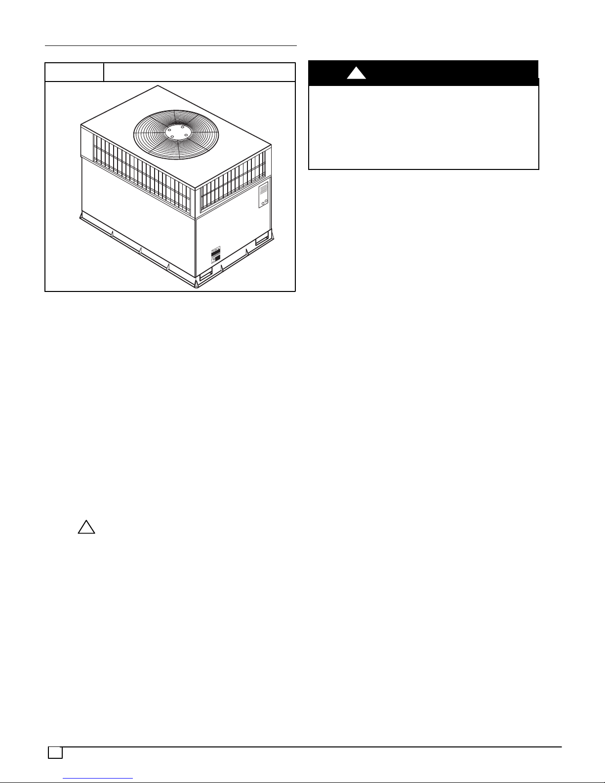
FIGURE 1
Installation and servicing of this equipment can be
hazardous due to mechanical and electrical components.
Only trained and qualified personnel should install, repair,
or service this equipment.
Untrained personnel can perform basic maintenance
functions such as cleaning and replacing air filters. All other
operations must be performed by trained service
personnel. When working on this equipment, observe
precautions in the literature, ontags, and on labels attached
to or shipped with the unit and other safety precautions that
may apply.
Follow all safety codes. Installation must be in compliance
with local and national building codes. Wear safety glasses,
protective clothing, and work gloves. Have fire extinguisher
available. Read these instructions thoroughly and follow all
warnings or cautions included in literature and attached to
the unit.
Recognize safety information. This is the safety--alert
symbol . When you see this symbol in instructions or
manuals, be alert to the potential for personal injury.
Understand the signal words DANGER, WARNING,
CAUTION, and NOTE. These words are used with the
safety--alert symbol. DANGER identifies the most serious
hazards which will result in serious injury or death.
WARNING signifies a hazard which could result in serious
injury or death. CAUTION is used to identify unsafe
practices which may result in minor personal injury or
product and property damage. NOTE is used to highlight
suggestions which will result in enhanced installation,
reliability, or operation.
These instructions cover minimum requirements and
conform to existing national standards and safety codes. In
some instances, these instructions exceed certain local
codes and ordinances, especially those that may not have
kept up with changing residential construction practices.
!
PAN3 AIR CONDITIONING UNIT
!
ELECTRICAL SHOCK HAZARD
Failure to follow this warning could result in personal
injury or death.
Before installing or servicing system, turn off power
supply to the unit and install lockout tag. There may be
more than one disconnect switch. Turn off accessory
heater power switch if applicable.
INTRODUCTION
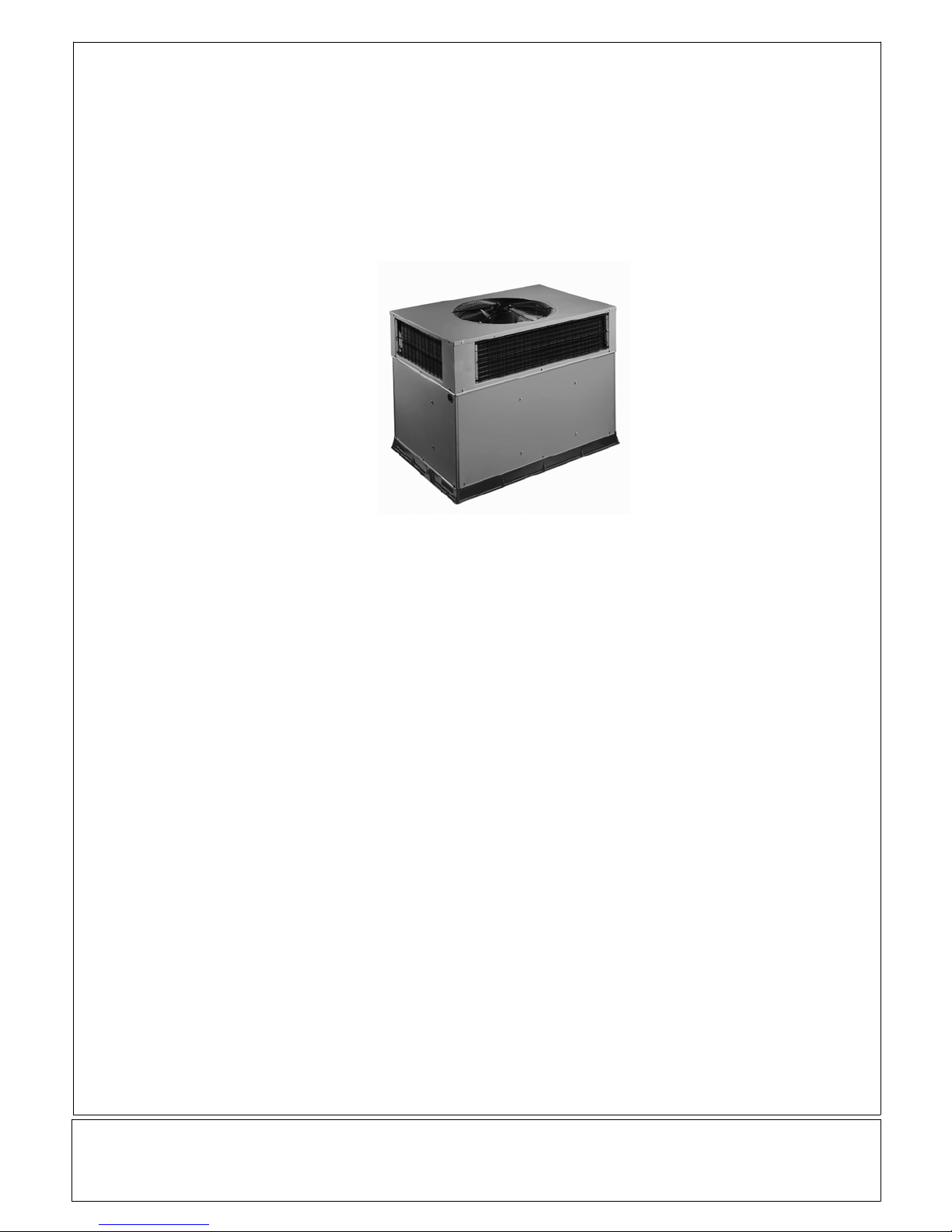
The PAN3 packaged air conditioner is fully self--contained
and designed for outdoor installation (see Fig. 1). See Fig. 3
and 4 for unit dimensions. All unit sizes have discharge
openings for both horizontal and downflow configurations
and are factory shipped with all downflow duct openings
covered. The unit may be installed e ither on a rooftop or at
ground level.
WARNING
RECEIVING AND INSTALLATION
Step 1—Check Equipment
IDENTIFY UNIT
The unit model number and serial number are stamped on
the unit information plate. Check this information against
shipping papers.
INSPECT SHIPMENT
Inspect for shipping damage while unit is still on shipping
pallet. If unit appears to be damaged or is torn loose from
its anchorage, have it examined by transportation
inspectors before removal. Forward claim papers directlyto
transportation company. Manufacturer is not responsible
for any damage incurred in transit. Check all items against
shipping list. Immediately notify the nearest equipment
distribution office if any item is missing. To prevent loss or
damage, leave all parts in original packages until
installation.
Step 2—Provide Unit Support
For hurricane tie downs, contact distributor for details and
PE (Professional Engineering) Certificate if required.
ROOFCURB
Install accessory roof curb in accordance with instructions
shipped with curb. Install insulation,cant strips, roofing, and
flashing. Ductwork must be attached to curb.
IMPORT ANT: The gasketing of the unit to the roof curb is
critical for a water tight seal. Install gasketing material
supplied with the roof curb. Improperly applied gasketing
also can result in air leaks and poor unit performance.
Curb should be level to within 1/4 in. (6mm). This is
necessary for unit drain to function properly. Refer to
accessory roof curb installation instructions for additional
information as required.
SLAB MOUNT
Place the unit on a solid, level concrete pad that is a
minimum of 4 in. (102mm) thick with 2 in. (51mm) above
grade (See Fig. 2). The slab should extend approximately
2
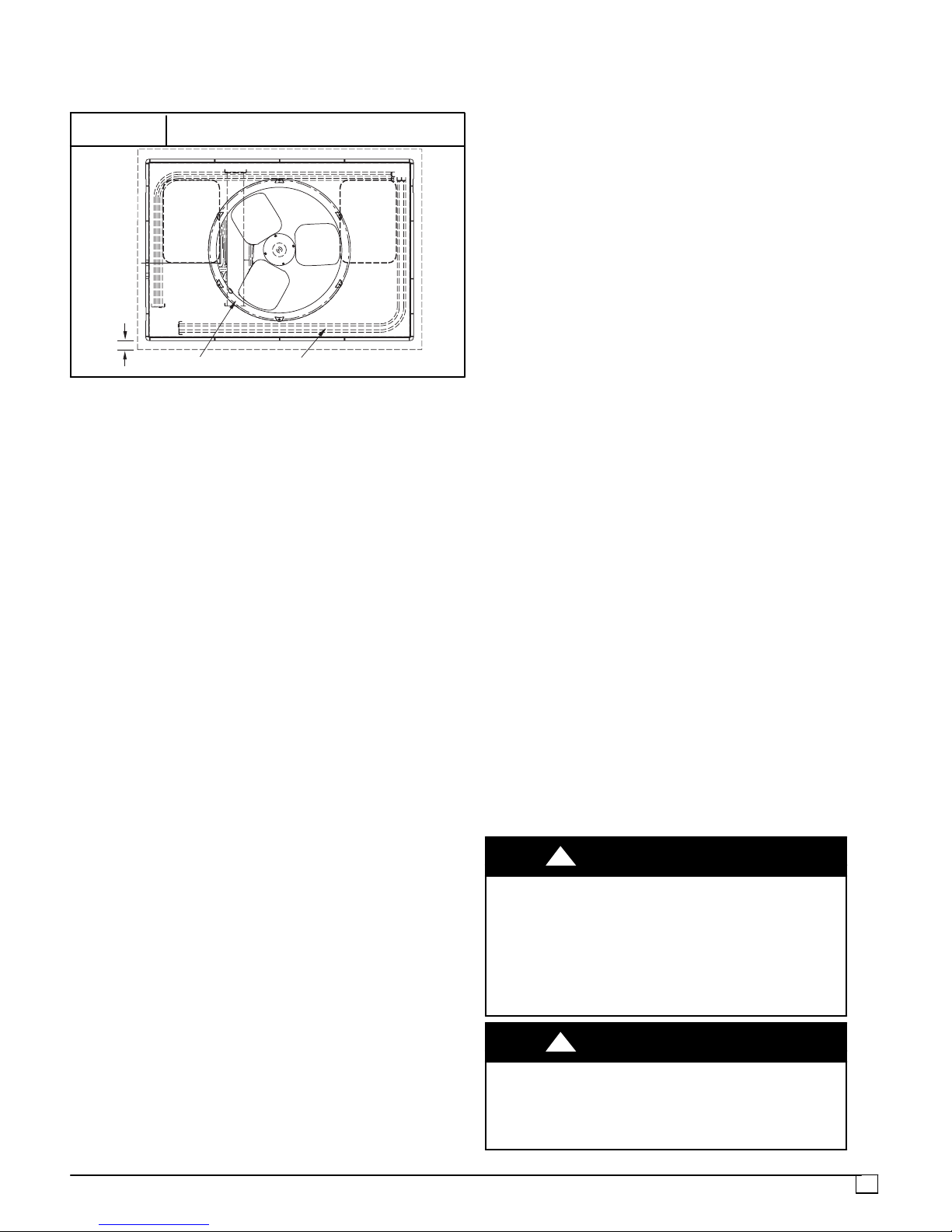
2 in. beyond the casing on a ll 4 sides of the unit. Do not
secure the unit to the slab except when required by local
codes.
FIGURE 2
2"
EVAP. COIL COND. COIL
Slab Mounting Details
OPTIONAL
RETURN
AIR
OPENING
OPTIONAL
SUPPLY
AIR
OPENING
ADDITIONAL GROUND LEVEL PLATFORM
REQUIREMENTS
The unit MUST be situated to provide safe access for
servicing.
The unit must be level and supported above grade by
beams, platform, or a pad.
Platform or pad can be of open or solid construction but
should be of permanent materials such as concrete, bricks,
blocks, steel, or pressure--treated timbers approved for
ground contact. Soil conditions must be considered so that
the platform or pad does not shift or settle and leave the unit
partially supported.
Position platform separate from building foundation.
Install in well--drained area, with top surface of platform
above grade level.
Platform must be high enough to allow for proper
condensate trap installation and drainage.
Step 3—Provide Clearances
The required minimumservice clearances areshown in Fig.
3 and 4. Adequate ventilation and outdoor air must be
provided. The outdoorfan draws air through the outdoor coil
and discharges it through the top fan grille. Be sure that the
fan discharge doesnot recirculate tothe outdoor coil.Do not
locate the unit in either a corner or under an overhead
obstruction. The minimum clearance under a partial
overhang (such as a normal house overhang) is 48 in.
(1219mm) above the unit top. The maximum horizontal
extension of a partial overhang must not exceed 48
in.(1219mm).
IMPORT ANT: Do not restrict outdoor airflow. An air
restriction at either the outdoor--air inlet or the fan discharge
may be detrimental to compressor life.
Do not place the unit where water, ice, or snow from an
overhang or roof will damage or flood the unit. Do not install
the unit on carpeting or other combustible materials.
Slab--mounted units should be at least 4 in. (102mm) above
the highest expected water and runoff levels. Do not use
unit if it has been under water.
Step 4—Field Fabricate Ductwork
Secure all ducts to roof curb and building structure on
vertical discharge units. Do not connect ductwork to unit.
For horizontal applications, unit is provided with flanges on
the horizontal openings. All ductwork should be secured to
the flanges. Insulate and weatherproof all external
ductwork, joints, and roof openings with counter flashing
and mastic in accordance with applicable codes.
Ducts passing through an unconditioned space must be
insulated and covered with a vapor barrier.
If a plenum return isused on a vertical unit,the return should
be ducted through the roof deck to comply with applicable
fire codes.
A minimum clearance is not required around ductwork.
Cabinet return--air static shall not exceed --.25 in. wc.
Step 5—Rig and Place Unit
Rigging and handling of this equipment can be hazardous
for many reasons due to the installation location (roofs,
elevated structures, etc.).
Only trained, qualified crane operators and ground support
staff should handle and install this equipment.
When working with this equipment, observe precautions in
the literature, on tags, stickers, and labels attached to the
equipment, and any other safety precautions that might
apply.
Training for operators of the lifting equipment should
include, but not be limited to, the following:
1. Application of the lifter to the load, and adjustment of
the lifts to adapt to various sizes or kinds of loads.
2. Instruction in any special operation or precaution.
3. Condition of the load as it relates to operation of the
lifting kit, such as balance, temperature, etc.
Follow all applicable safety codes. Wear safety shoes and
work gloves.
INSPECTION
Prior to initial use, and at monthly intervals, all rigging
brackets and straps should be visually inspected for any
damage, evidence of wear, structural deformation, or
cracks. Particular attention should be paid to excessive
wear at hoist hooking points and load support areas.
Brackets or straps showing any kind of wear in these areas
must not be used and should be discarded.
!
ELECTRICAL SHOCK HAZARD
Failure to follow this warning could result in personal
injury or death.
Before installing or servicing system, always turn off
main power to system. There may be more than one
disconnect switch. Turn off accessory heater power
switch if applicable. Tag disconnect switch with a suitable
warning label.
!
UNIT FALLING HAZARD
Failure to follow this warning could result in personal
injury or death.
Never stand beneath rigged units or lift over people.
WARNING
WARNING
3
!
WARNING
!
WARNING
PROPERTY DAMAGE HAZARD
Failure to follow this warning could result in personal
injury/death or property damage.
Rigging brackets for one unit use only. When
removing a unit at the end of its useful life, use a new set
of brackets.
USE OF RIGGING BRACKET
NOTE: Rigging brackets are factory installed on 3--phase
units only. Single--Phase units require accessory kit
NPLIFTBK003A10.
Field Installation of Rigging Bracket (if not already installed)
1. Remove unit from shipping carton. Leave top shipping
skid on the unit for use as a spreader bar to prevent the
rigging straps from damaging the unit. If the skid is not
available, use a spreader bar of sufficient length to
protect the unit from damage.
2. Remove 4 screws in unit corner posts.
3. Attach each of the 4 metal rigging brackets under the
panel rain lip (See Fig. 5). Use the screws removed in
step 2 above to secure the brackets to the unit.
!
WARNING
PROPERTY DAMAGE HAZARD
Failure to follow this warning could result in personal
injury/death or property damage.
Do not strip screws when re--securing the unit. If a screw
is stripped, replace the stripped one with a larger diameter
screw (included). When straps are taut, the clevis should
be a minimum of 36 (914mm) inches above the unit top
cover .
Rigging/Lifting of Unit
1. Bend top of brackets down approximately 30 degrees
from the corner posts.
2. Attach straps of equal length to the rigging brackets at
opposite ends of the unit. Be sure straps are rated to
hold the weight of the unit (See Fig. 5).
3. Attach a clevis of sufficient strength in the middle of the
straps. Adjust the clevis location to ensure unit is lifted
level with the ground.
4. After unit is securely in place detach rigging straps.
Remove corner posts screws, and rigging brackets
then reinstall screws.
After the unit is placed on the roof curb or mounting pad,
remove the top crating.
PROPERTY DAMAGE HAZARD
Failure to follow this warning could result in personal
injury/death or property damage.
Rigging bracket MUST be under the rain lip to provide
adequate lifting.
4
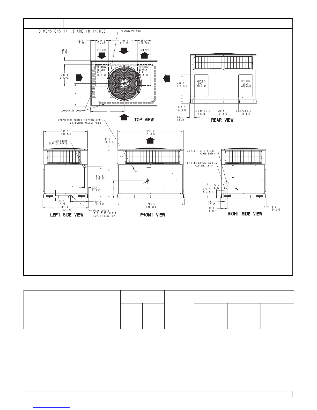
FIGURE 3
*
PAN324--36 DIMENSIONS
REQUIRED CLEARANCE TO COMBUSTIBLE MATL
(
R
efe
r t
o
M
aximu
m
O
perating
C
learance
TOP OF UNIT...................................................................................14.00 [355.6]
DUCT SIDE OF UNIT.........................................................................2.00 [50.8]
SIDE OPPOSITE DUCTS ................................................................14.00 [355.6]
BOTTOM OF UNIT.............................................................................0.50 [12.7]
NEC. REQUIRED CLEARANCES.
BETWEEN UNITS, POWER ENTRY SIDE ....................................42.00 [1066.8]
UNIT AND UNGROUNDED SURFACES, POWER ENTRY SIDE .36.00 [914.0]
UNIT AND BLOCK OR CONCRETE WALLS AND OTHER
GROUNDED SURFACES, POWER ENTRY SIDE.........................42.00 [1066.8]
UNIT
ELECTRICAL
CHARACTERISTICS
.
s
)
INCHES [mm]
INCHES [mm]
UNIT WEIGHT
lb kg X Y
REQUIRED CLEARANCE FOR OPERATION AND SERVICING
EVAP. COIL ACCESS SIDE............................................................36.00 [914.0]
POWER ENTRY SIDE....................................................................42.00 [1066.8]
(EXCEPT FOR NEC REQUIREMENTS)
UNIT TOP.......................................................................................48.00 [1219.2]
SIDE OPPOSITE DUCTS ..............................................................36.00 [914.0]
DUCT PANEL .................................................................................12.00 [304.8]
*Minimum distances: if unit is placed less than 304.8 (12.00) from wall
*MINIMUM DISTANCES: IF UNIT IS PLACED LESS THAN 304.8 [12.00] FROM
system, then systerm performance may be compromised.
WALL SYSTEM, THEN SYSTEM PERFORMANCE MAYBE COMPROMISE.
UNIT
HEIGHT
IN. [MM]
CENTER OF GRAVITY
IN. [MM]
“A”
INCHES [mm]
Z
PAN324 208/230--1--60 318 144 37 [940] 20.0 [508] 17.0 [431] 17.6 [447]
PAN330 208/230--1--60 330 150 39 [991] 20.0 [508] 19.3 [490] 13.0 [330]
PAN336 208/230--1--60 339 152 41 [1042] 21.0 [533] 21.0 [533] 16.6 [422]
5
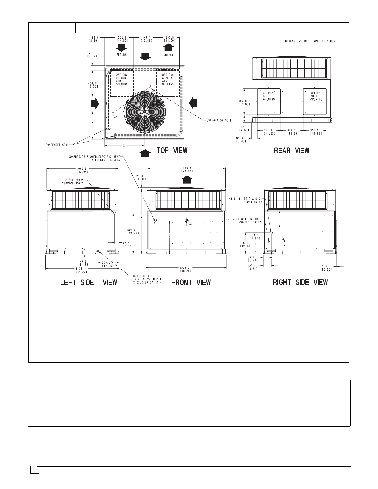
FIGURE 4
*
[
]
PAN342--60 DIMENSIONS
REQUIRED CLEARANCE TO COMBUSTIBLE MATL
(
R
efe
r t
o
M
aximu
m
O
perating
C
learance
TOP OF UNIT...................................................................................14.00 [355.6]
DUCT SIDE OF UNIT.........................................................................2.00 [50.8]
SIDE OPPOSITE DUCTS ................................................................14.00 [355.6]
BOTTOM OF UNIT.............................................................................0.50 [12.7]
NEC. REQUIRED CLEARANCES.
BETWEEN UNITS, POWER ENTRY SIDE ....................................42.00 [1066.8]
UNIT AND UNGROUNDED SURFACES, POWER ENTRY SIDE .36.00 [914.0]
UNIT AND BLOCK OR CONCRETE WALLS AND OTHER
GROUNDED SURFACES, POWER ENTRY SIDE.........................42.00
UNIT
ELECTRICAL
CHARACTERISTICS
.
s
)
INCHES [mm]
INCHES [mm]
1066.8
REQUIRED CLEARANCE FOR OPERATION AND SERVICING
EVAP. COIL ACCESS SIDE............................................................36.00 [914.0]
POWER ENTRY SIDE....................................................................42.00 [1066.8]
(EXCEPT FOR NEC REQUIREMENTS)
UNIT TOP.......................................................................................48.00 [1219.2]
SIDE OPPOSITE DUCTS ..............................................................36.00 [914.0]
DUCT PANEL .................................................................................12.00 [304.8]
*Minimum distances: if unit is placed less than 304.8 (12.00) from wall
*MINIMUM DISTANCES: IF UNIT IS PLACED LESS THAN 304.8 [12.00] FROM
system, then systerm performance may be compromised.
WALL SYSTEM, THEN SYSTEM PERFORMANCE MAYBE COMPROMISE.
UNIT WEIGHT
lb kg X Y
UNIT
HEIGHT
IN. [MM]
“A”
CENTER OF GRAVITY
IN. [MM]
INCHES [mm]
PAN342 208/230--1--60 412 187 40.98 [1041] 21.0 [533] 21.0 [533] 17.1 [434]
PAN348 208/230--1--60 442 201 46.98 [1193] 21.0 [533] 20.0 [508] 17.4 [442]
PAN360 208/230--1--60 446 202 46.98 [1193] 21.0 [533] 20.0 [508] 17.6 [447]
6
Z
 Loading...