

International comfort products PAE Series Installation Instructions Manual
Installation Instructions
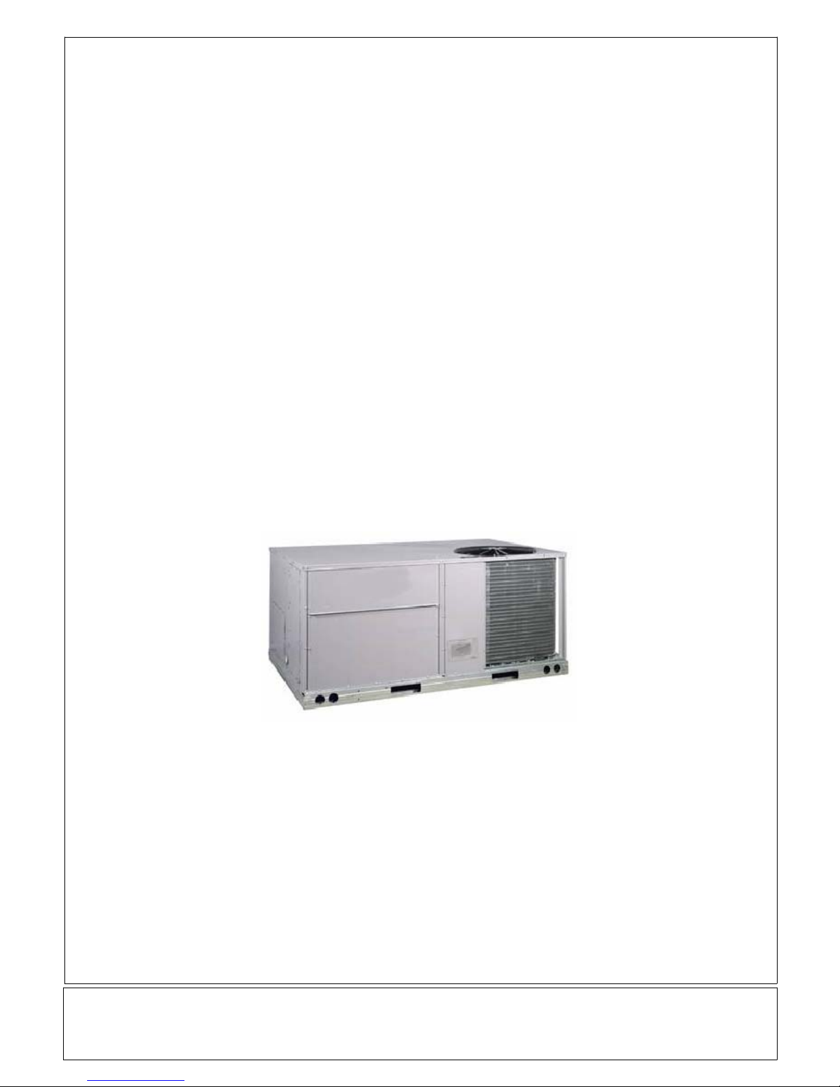
PAE Series -- 3 Phase
3to6Ton
PACKAGED AIR CONDITIONING UNITS
Printed in U.S.A.
Code: PAE
International Comfort Products, LLC
Lewisburg, TN. 37091
522 01 1001 01 01--15--08
IMPORTANT -- READ BEFORE INSTALLING
1. Read and become familiar with these installation
instructions before installing this unit (Fig. 1A and1B).
2. Be sure the installation conforms to all applicable local and
national codes.
3. These instructions contain important information for the
proper maintenance and repair of this equipment. Retain
these instructions for future use.
CONTENTS
Installation 2
Step 1. -- Provide Unit Support 2
Step 2. -- Field Fabricate Ductwork 5
Step 3. -- Install External Trap for Condensate Drain 5
Step 4. -- Rig and Place Unit 5
Step 5. -- Make Electrical Connections 9
Step 6. -- Adjust Factory--Installed Options 16
Step 7. -- Adjust Evaporator--Fan Speed 24
PRE--START--UP 37
START--UP 37
SERVICE 39
TROUBLESHOOTING 43
START--UP CHECKLIST 47
SAFE INSTALLATION REQUIREMENTS
Installation and servicing of this equipment can be hazardous
due to mechanical and electricalcomponents. Only trained and
qualified personnel should install, repair, or service this
equipment.
Untrained personnel can perform basic maintenance functions
such as cleaning and replacing air filters. All other operations
must be performed by trained service personnel. When
working on this equipment, observe precautions in the
literature, on tags, and on labels attached to or shipped with the
unit and other safety precautions that may apply.
Follow all safety codes. Installation must be in compliance with
local and national building codes. Wear safety glasses,
protective clothing, and work gloves. Have fire extinguisher
available. Read these instructions thoroughly and follow all
warnings or cautions included in literature and attached to the
unit.
Recognize safety information. This is the safety--alert
symbol . When you see this symbolin instructions or manuals,
be alert to the potential for personal injury.
Understand the signal words DANGER, WARNING,
CAUTION, and NOTE. These words are used with the
safety--alert symbol. DANGER identifies the most serious
hazards which will result in serious injury or death. WARNING
!
signifies a hazard which could result in serious injury or death.
CAUTION is used to identify unsafe practices which may result
in minor personal injury or product and property damage.
NOTE is used to highlight suggestions which will result in
enhanced installation, reliability, or operation.
These instructions cover minimum requirements and conform
to existing national standards and safety codes. In some
instances, these instructions exceed certain local codes and
ordinances, especially those that may not have kept up with
changing residential construction practices. We require these
instructions as a minimum for a safe installation.
!
ELECTRICAL SHOCK HAZARD
Failure to follow this warning could result in personal injury or
death.
Before installing or servicing system, always turn off power
supply to unit and install lockout tag. There may be more than
one disconnect switch. Turn off accessory heater power switch
if applicable.
!
PROPERTY DAMAGE HAZARD
Failure to follow this caution can cause damage to the unit.
Ensure voltage listed on unit data plate agrees with electrical
supply provided for the unit.
WARNING
CAUTION
INSTALLATION
The unit is shipped in the vertical discharge configuration. To
convert to horizontal configuration, remove the horizontal duct
opening covers. Using the same screws, install the covers on
the duct openings in the basepan of the unit with the
insulation--side down. Seals around duct openings must be
tight. See Fig. 2.
Step 1—PROVIDE UNIT SUPPORT
Roofcurb
Assemble and install accessory roof curb in accordance with
instructions shipped with curb. Install insulation, cant strips,
roofing felt, and counter flashing as shown. Ductwork must be
attached to curb, not to unit. If electric or control power is to be
routed through the basepan, attach the accessory
thru-the-bottom service connections to the basepan in
accordance with the accessory installation instructions.
Connection must be installed before unit is set on roof curb.
IMPORT ANT: The gasketing of the unit to the roof curb is
critical for a water tight seal. Install gasketing material supplied
with the roof curb. Improperly applied gasketing also can result
in air leaks and poor unit performance.
Curb should be level. This is necessary for the unit drain to
function properly. Unit leveling tolerances are shown in Fig. 3.
Refer to Accessory Roof Curb Installation Instructions for
additional information as required.
2
522 01 1001 01
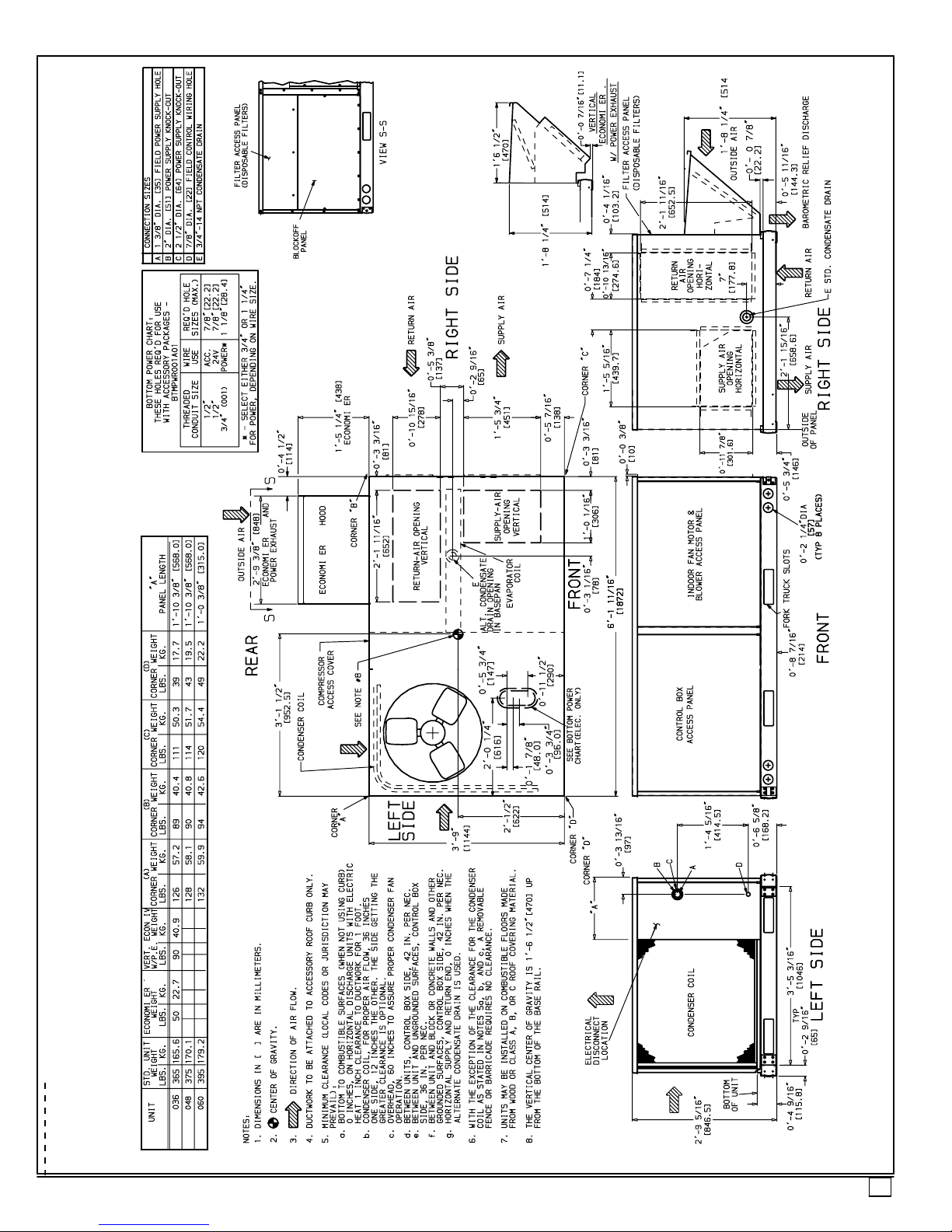
FIGURE 1
A
Base Unit Dimensions:
PAE036--60
Z
DN
Z
Z
Z
Z
PAE
PAE
PAE
522 01 1001 01
3
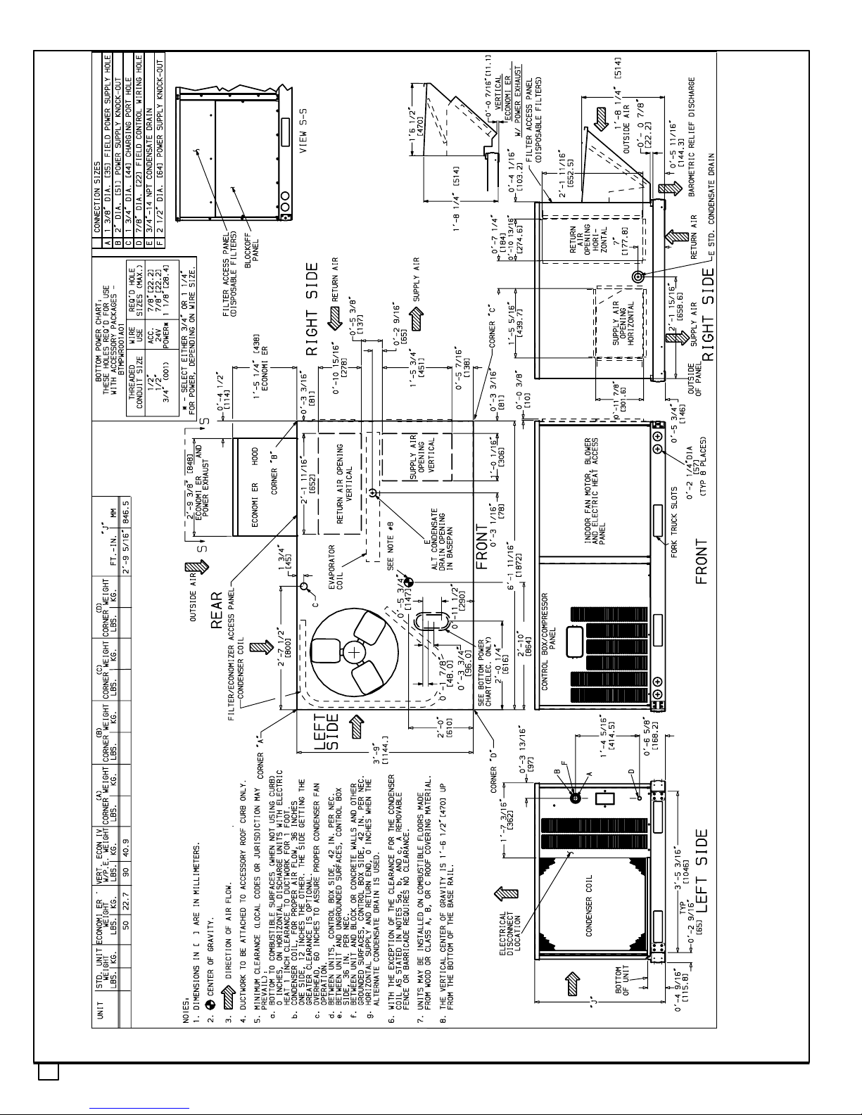
Figure 1B
Base Unit Dimensions:
PAE072
Z
DN
Z
132
50.8
112
57.6
67.6 127
149520
Z
Z
Z
236
PAE072 59.9
4
522 01 1001 01
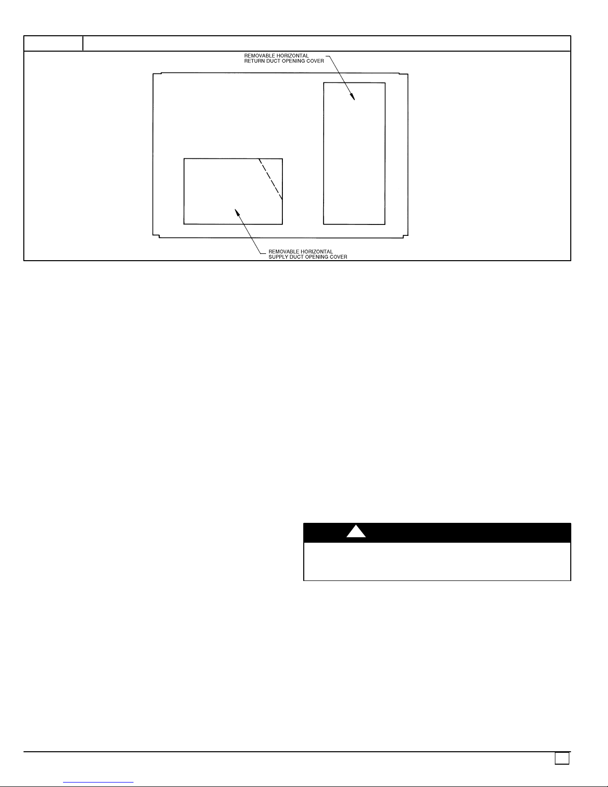
FIGURE 2
HORIZONTAL CONVERSION PANELS
Slab Mount (Horizontal Units Only)
Provide a level concrete slab that extends a minimum of 6 in.
beyond the unit cabinet. Install a gravel apron in front of the
condenser coil air inlet to prevent grass and foliage from
obstructing airflow.
NOTE: Horizontal units may be installed on the roof curb if
required.
Alternate Unit Support
When the curb or adapter cannot be used, support unit with
sleeper rails using unit curb or adapter support area. If sleeper
rails cannot be used, support the long sides of the unit with a
minimum of 3 equally spaced 4--in. x 4--in. pads on each side.
Step 2—FIELD FABRICATE DUCTWORK
Secure all ducts to roof curb and building structure on vertical
discharge units. Do not connect ductwork to unit. For horizontal
applications, field--supplied flanges should be attached to
horizontal discharge openings and all ductwork should be
attached to the flanges. Insulate and weatherproof all external
ductwork, joints, and roof openings with counter flashing and
mastic in accordance with applicable codes.
Ducts passing through an unconditioned space must be
insulated and covered with a vapor barrier.
If a plenum return is used on a vertical unit, the return should
be ducted through the roof deck to comply with applicable fire
codes.
A minimum clearance is not required around ductwork. Cabinet
return air static pressure (a negative condition) should not
exceed 0.35 in. wg with economizer or 0.45 in. wg without
economizer.
Step 3—INSTALL EXTERNAL TRAP FOR CONSENSATE
DRAIN
The unit’s 3/4--in. condensate drain connections are located on
the bottom and side of the unit. Unit discharge connections do
not determine the use of drain connections; either drain
connection can be used with vertical or horizontal applications.
When using the standard side drain connection, make sure the
plug (Red) in the alternate bottom connection is tight before
installing the unit.
To use the bottom drain connection for a roof curb installation,
relocate the factory--installed plug (Red) from the bottom
connection to the side connection. The center drain plug looks
like a star connection, however it can be removed with a 1/2--in.
socket drive. See Fig. 4. The piping for the condensate drain
and external trap can be completed after the unit is in place.
All units must have an external trap for condensate drainage.
Install a trap at least 4--in. deep and protect against freeze--up.
If drain line is installed downstream from the external trap, pitch
the line away from the unit at 1 in. per 10 ft of run. Do not use
a pipe size smaller than unit connection (3/4 in.). See Fig. 5.
Step 4—RIG AND PLACE UNIT
Inspect unit for transportation damage. File any claim with
transportation agency. Keep unit upright and do not drop.
Spreader bars are not required if top crating is left on unit.
Rollers may be used to move unit across a roof. Level by using
unit frame as a reference. See Table 1 and Fig.6 for additional
information. See operating weight in Table 1 and Fig. 1A and
1B.
Lifting holes are provided in base rails as shown in Fig. 6. Refer
to rigging instructions on unit.
!
PROPERTY DAMAGE HAZARD
Failure to follow this caution may result in property damage.
All panels must be in place when rigging and lifting.
CAUTION
Positioning
Maintain clearance around and above unit to provide proper
airflow and service access. See Fig. 1A and 1B. A properly
1
positioned unit will have the following clearances:
/4-in.
clearance between roof curb and base rails on each side and
1
duct end of unit;
/4-in. clearance between roof curb and
condenser coil end of unit.
Do not install unit in an indoor location. Do not locate unit air
inlets near exhaust vents or other sources of contaminated
air.
Although unit is weatherproof, guard against water from higher level runoff and overhangs. After unit is in position, remove
shipping materials and top crating.
522 01 1001 01
5
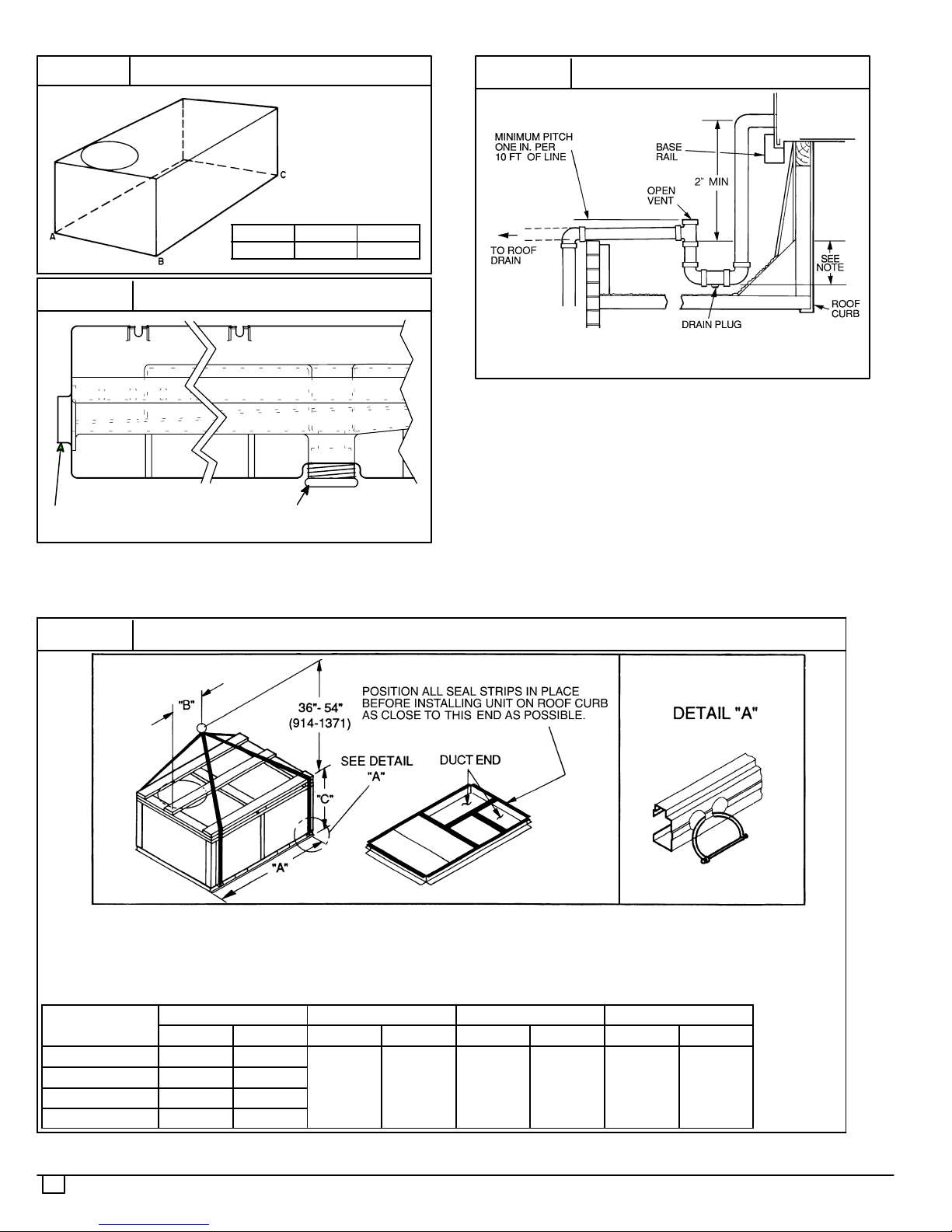
FIGURE 3
Unit Leveling Tolerances
MAXIMUM ALLOWABLE
A--B B--C A--C
0.5 1.0 1.0
FIGURE 5
Condensate Drain Piping Details
FIGURE 4
Horizontal Drain Outlet
Condensate Drain Connection
Drain Plug
NOTE: Drain plug is shown in factory--- installed position.
FIGURE 6
Rigging Details
NOTE: Trap should be deep enough to offset maximum unit static
difference.
A 4--in. trap is recommended.
NOTES:
1. Dimensions in ( ) are in millimeters.
2. Hook rigging shackles through holes in base rail, as shown in
detail “A.” Holes in base rails are centered around the unit center
of gravity. Use wooden top skid when rigging to prevent rigging
straps from damaging unit.
PAE UNIT SIZE
MAX. WEIGHT A B C
lb. kg In. mm In. mm In. mm
036 415 188
048 425 193
060 445 202
072 570 259
6
3. Unit weights do not include economizer. See Table 1 for econo-mizer weights.
73.69 1872 35.0 889 33.35 847
522 01 1001 01
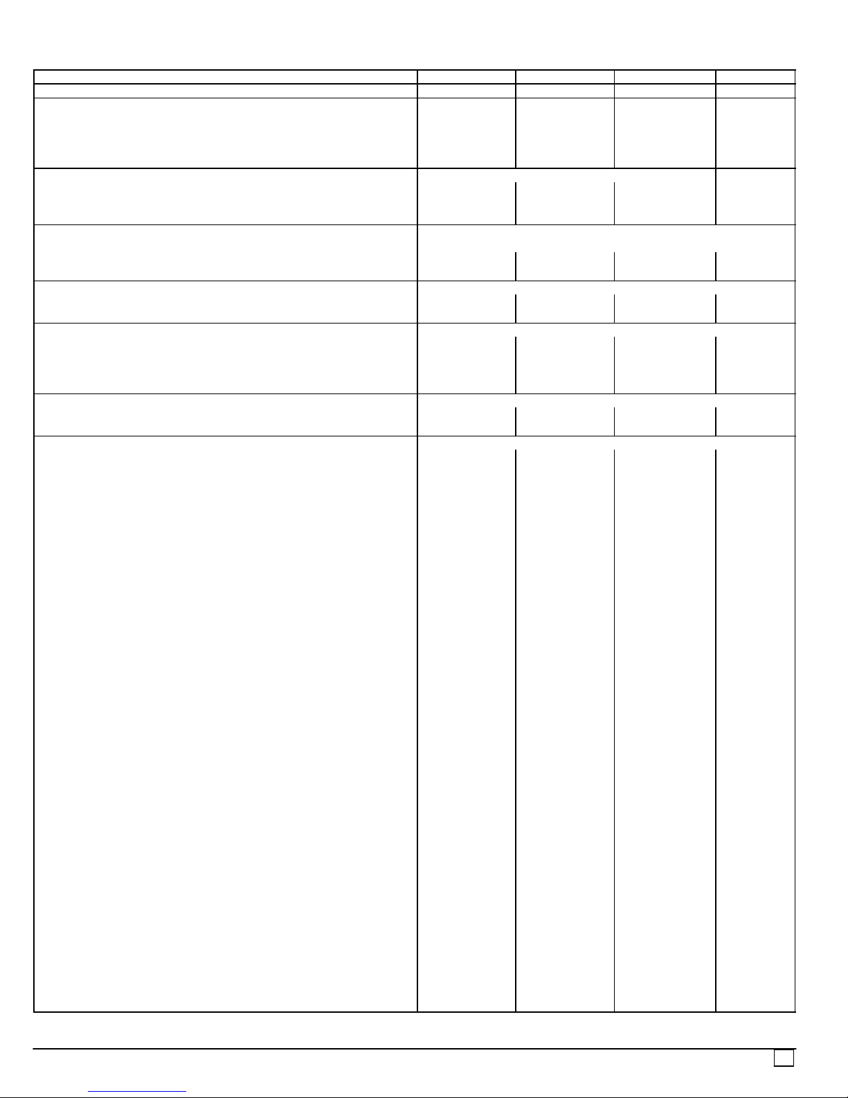
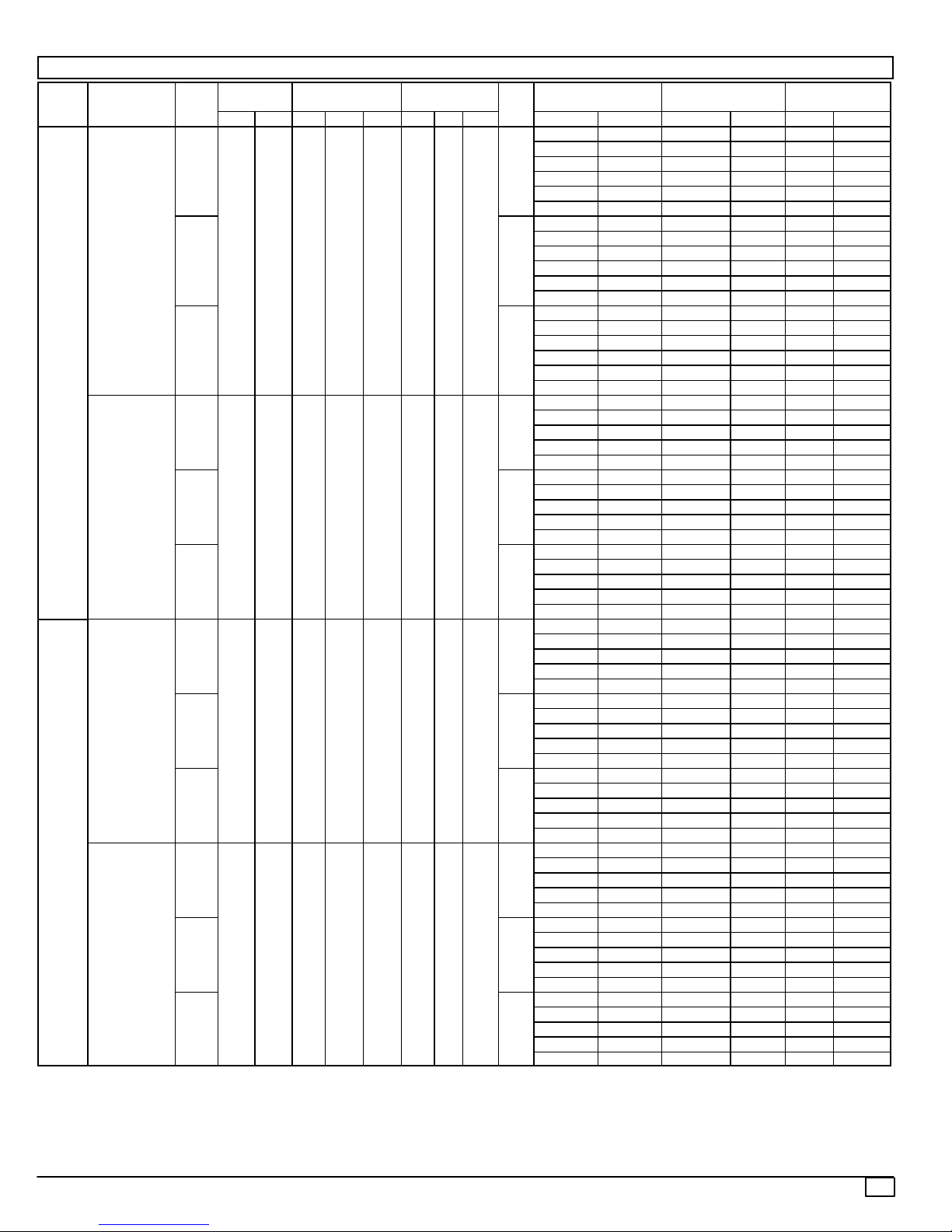
Table 1—Physical Data -- PAE036--72
PAE UNIT SIZE
NOMINAL CAPACITY (tons) 3 4 5 6
OPERATING WEIGHT (lb) Unit
Al/Al* 365 375 395 520
Cu/Cu* 373 387 402 —
Economizer 50 50 50 50
Roof Curb† 115 115 115 115
COMPRESSOR Reciprocating Scroll
Quantity 1 1 1 1
No. Cylinders (per Circuit) 2 2 2 2
Oil (oz) 50 50 50 60
REFRIGERANT TYPE R-22
Expansion Device Fixed Orifice Metering Device
Operating Charge (lb-oz)
Circuit 1 4-4 6-6 6-14 11-0
CONDENSER COIL Enhanced Copper Tubes, Aluminum Lanced Fins
Rows...Fins/in. 1...17 2...17 2...17 2...17
Total Face Area (sq ft) 8.36 8.36 10.42 16.5
CONDENSER FAN Propeller Type
Nominal Cfm 3500 4000 4000 4100
Quantity...Diameter (in.) 1...22.0 1...22.0 1...22.0 1...22.0
Motor Hp...Rpm
Watts Input (Total) 325 325 325 320
EVAPORATOR COIL Enhanced Copper Tubes, Aluminum Double-Wavy Fins
Rows...Fins/in. 2...15 2...15 3...15 4...15
Total Face Area (sq ft) 4.17 5.5 5.5 5.5
EVAPORATOR FAN Centrifugal Type
Quantity...Size (in.) Std 1...10 x 10 1...10 x 10 1...11 x 10 1...10 x 10
Alt 1...10 x 10 1...10 x 10 1...10 x 10 —
High-Static 1...10 x 10 1...10 x 10 1...11 x 10 1...10 x 10
Typ e Driv e Std Direct Direct Direct Belt
Alt Belt Belt Belt —
High-Static Belt Belt Belt Belt
Nominal Cfm 1200 1600 2000 2100
Maximum Continuous Bhp Std .34 .75 1.20 2.40
Alt 1.20 1.20 1.30/2.40** —
High-Static 2.40 2.40 2.90 2.90
Motor Frame Size Std 48 48 48 56
Alt 48 48 56 —
High-Static 56 56 56 56
Nominal Rpm High/Low (Direct Drive) Std 860/800 1075/970 1075/970 —
Fan Rpm Range Std — — — 1070-1460
Alt 685-1045 770-1175 878-1192 —
High-Static 1075-1455 1075-1455 1300-1685 1300-1685
Motor Bearing Type Ball Ball Ball Ball
Maximum Allowable Rpm 2100 2100 2100 2100
Motor Pulley Pitch Diameter Min/Max (in.) Std — — — 2.8/3.8
Alt 1.9/2.9 1.9/2.9 2.4/3.4 —
High-Static 2.8/3.8 2.8/3.8 3.4/4.4 3.4/4.4
Nominal Motor Shaft Diameter (in.) Std
Alt
High-Static
Fan Pulley Pitch Diameter (in.) Std — — — 4.5
Alt 4.5 4.0 4.5 —
High-Static 4.5 4.5 4.5 4.5
Belt, Quantity...Type...Length (in.) Std — — — 1...A...40
Alt 1...A...34 1...A...34 1...A...39 —
High-Static 1...A...39 1...A...39 1...A...40 1...A...40
Pulley Center Line Distance (in.) Std — — — 14.7-15.5
Alt 10.0-12.4 10.0-12.4 14.7-15.5 —
High-Static 10.0-12.4 10.0-12.4 14.7-15.5 14.7-15.5
Speed Change per Full Turn of Std — — — 80
Movable Pulley Flange (rpm) Alt 48 70 80 —
High-Static 65 65 60 60
Movable Pulley Maximum Full Turns Std — — — 5
From Closed Position Alt 5 5 6 —
High-Static 6 6 5 5
036 048 060 072
1
/4...1100
1
/
2
1
/
2
5
/
8
1
/4...1100
1
/
2
1
/
2
5
/
8
1
/4...1100
1
/
2
5
/
8
5
/
8
1
/4...1100
5
/
8
—
7
/
8
522 01 1001 01
7
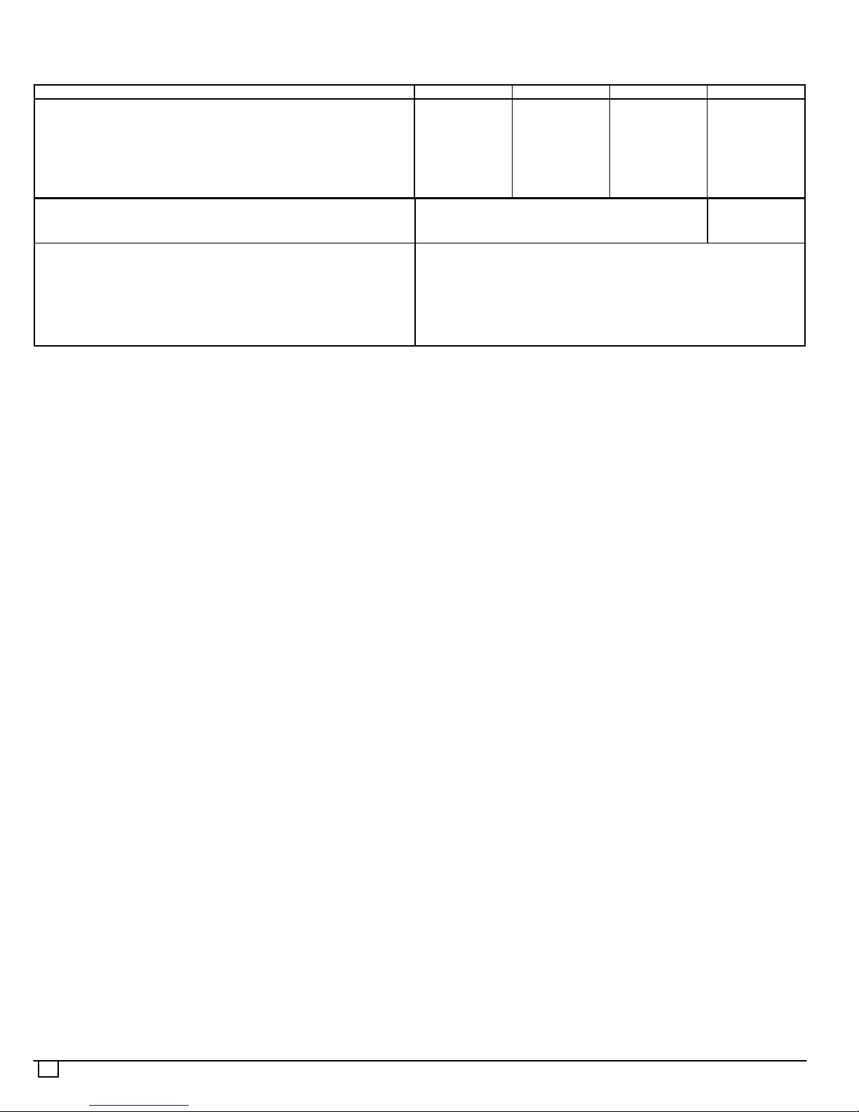
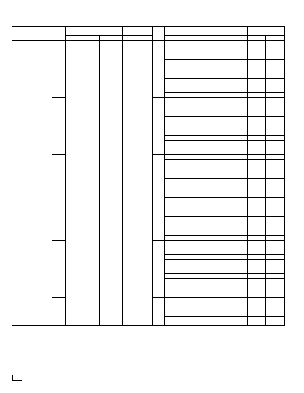
Table 1—Physical Data -- PAE036--72 (Cont.)
PAE UNIT SIZE
036 048 060 072
Factory Setting Std — — — 3
Alt 3 3 3 —
High-Static 31/
2
31/
2
31/
2
31/
Factory Speed Setting (rpm) Std — — — 1226
Alt 829 932 1035 —
High-Static 1233 1233 1416 1416
Fan Shaft Diameter at Pulley (in.)
High Pressure Switch (psig) 450 ± 50 500 ± 50
5
/
8
5
/
8
5
/
8
5
/
Internal Relief (Differential) Cutout 428 428
Reset (Auto.) 320 320
Low Pressure Switch (psig) Cutout 7 ± 3
Reset (Auto.) 22 ± 7
Freeze Protection Thermostat (F) Opens 30 ± 5
Closes 45 ± 5
OUTDOOR-AIR INLET SCREENS Cleanable. Screen size and quantity varies with option selected.
RETURN-AIR FILTERS Throwaway
Quantity...Size (in.) 2...16 x 25 x 2
LEGEND
Al -- Aluminum
Bhp -- Brake Horsepower
Cu -- Copper
*Condenser coil fin material.
{Weight of 14--in. roof curb.
2
8
8
522 01 1001 01
Step 5—MAKE ELECTRICAL CONNECTIONS
!
Failure to follow this warning could result in the installer being liable
for personal injury of others.
Unit cabinet must have an uninterrupted, unbroken electrical
ground to minimize the possibility of personal injury if an electrical
fault should occur. This ground may consist of electrical wire
connected to unit ground lug in control compartment, or conduit
approved for electrical ground when installed in accordance with
NEC (National Electrical Code), ANSI/NFPA (American National
Standards Institute/National Fire Protection Association) 70 (latest
year), and local electrical codes.
WARNING
All units except 208/230-v unitsare factory wired for the voltage
shown on the nameplate. If the 208/230-v unit is to be
connected to a 208-v power supply, the transformer must be
1
rewired by moving the black wire from 230-v
1
terminal and connecting it to 208-v
/4-in. spade terminal of
/4-in. spade
transformer.
Refer to unit label diagram and Electrical Data Tables 2A and
2B for additional information. Pigtails are provided for field wire
connections. Use factory-supplied splices or UL (Underwriters’
Laboratories) approved copper/aluminum connector.
When installing units, provide a disconnect per the NEC.
All field wiring must comply with NEC and local requirements.
Install field wiring as follows:
1. Install conduit through side panel openings. Install conduit
between disconnect and control box.
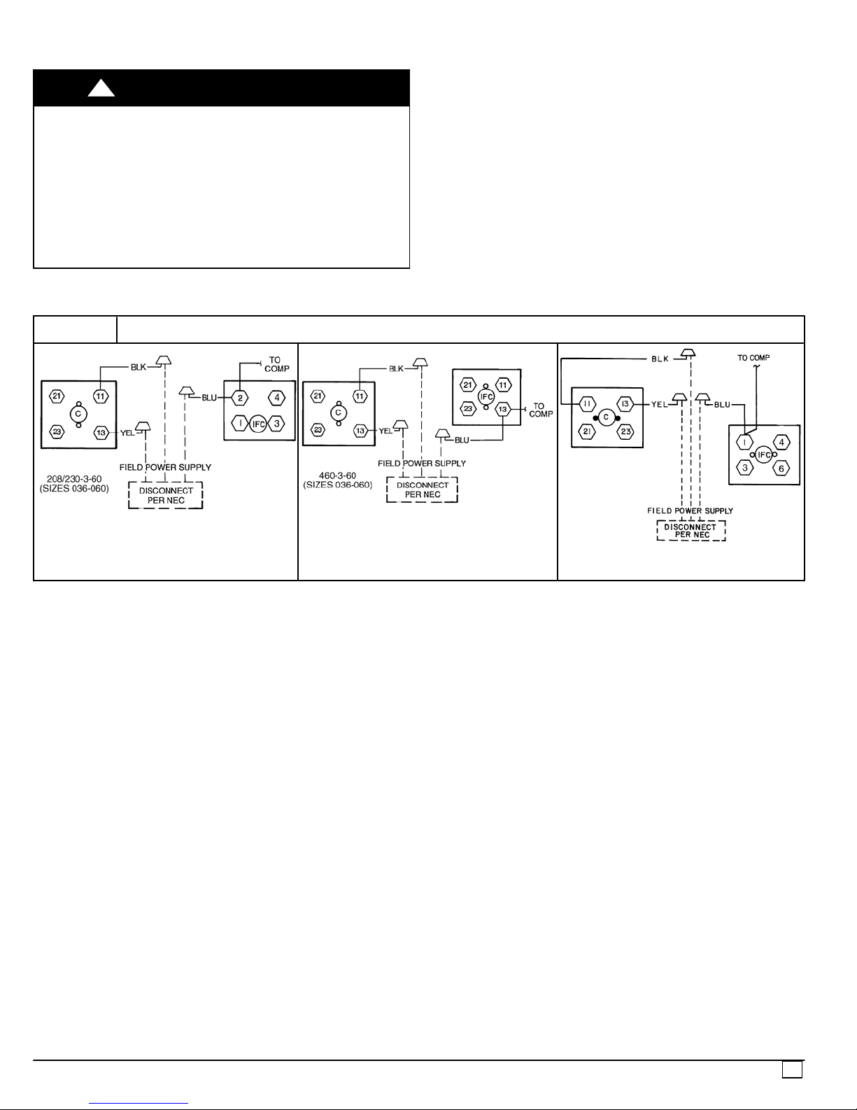
2. Install power lines to terminal connections as shown in Fig.
8.
FIGURE 7
LEGEND
C -- Contactor
COMP -- Compressor
IFC -- Indoor--Fan Contactor
NEC -- National Electric Code
TB -- Terminal Block
POWER WIRING CONNECTIONS
Field Power Supply
Install an approved accessory thermostat assembly according
to installation instructions included with the accessory. Locate
thermostat assembly on a solid wall in the conditioned space
to sense average temperature in accordance with thermostat
installation instructions. Connect thermostat wires to terminal
board.
Route thermostat cable or equivalent single leads of colored
wire from subbase terminals through connector on unit to
low--voltage connections (shown in Fig. 9).
NOTE: For wire runs up 50 ft, use no. 18 AWG (American Wire
Gage) insulated wire (35 C minimum). For 50 to 75 ft, use no.
16 AWG insulated wire (35 C minimum). For over 75 ft, use no.
14 AWG insulated wire (35 C minimum). All wire larger than no.
208/230--3--60
460--3--60
(SIZE 072)
18 AWG cannot be directly connectedto the thermostat and will
require a junction box and splice at the thermostat.
Pass the control wires through the hole provided in the corner
post; then feed wires through the raceway built into the corner
post to the 24--v barrier located on the left side of the control
box. See Fig. 10. The raceway provides the UL required
clearance between high--voltage and low--voltage wiring.
NOTE: If thru-the-bottom power connections are used refer
to the accessory installation instructions for information on
power wiring. Refer to Fig. 1A and 1B for drilling holes in
basepan.
IMPORT ANT: Optional factory-installed, alternate evaporator
fan motors are not available for PAE072 units.
522 01 1001 01
9
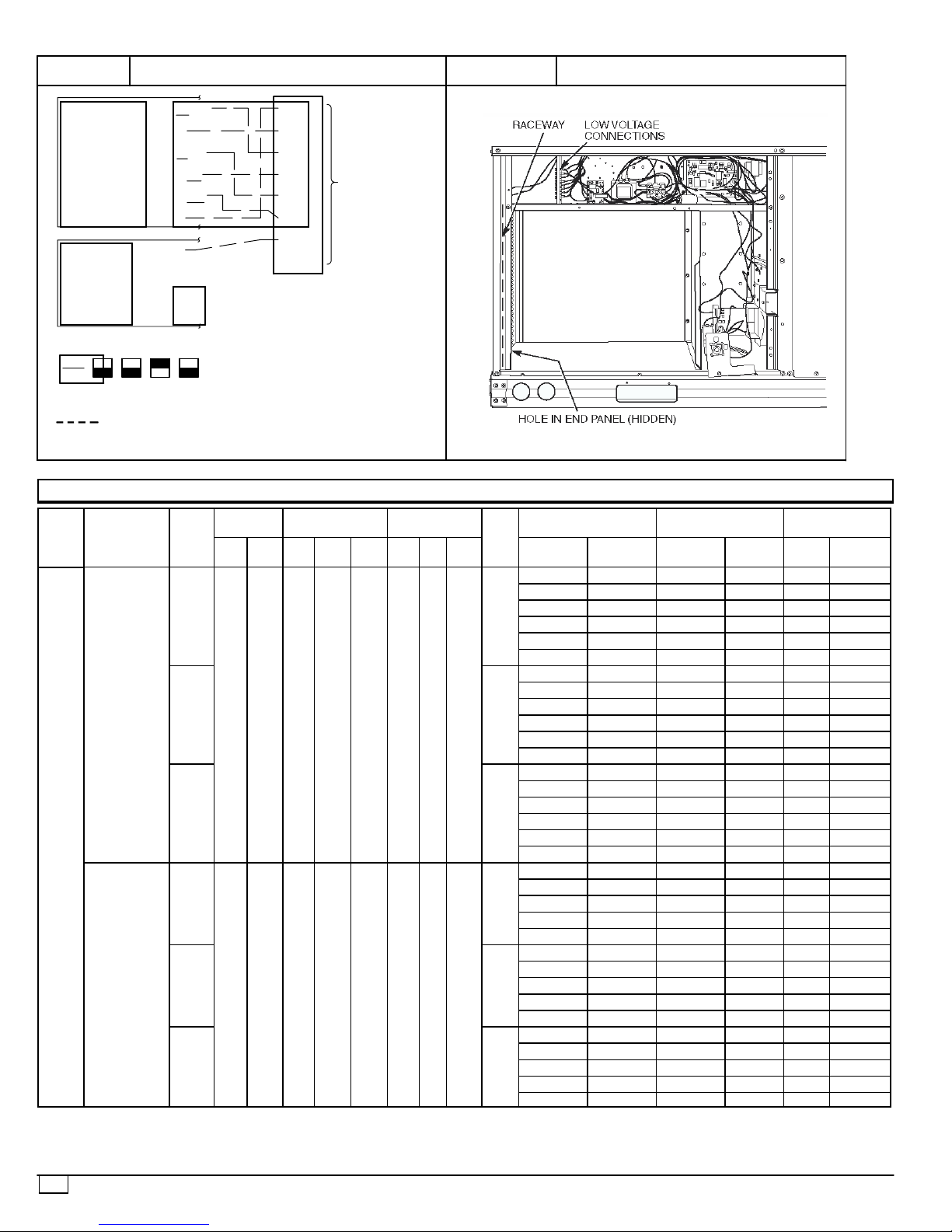
FIGURE 8
LOW VOLTAGE CONNECTIONS
FIGURE 9
FIELD CONTROL WIRING RACEWAY
COOL STAGE 1
FAN
HEAT STAGE 1
COOL STAGE 2
HEAT STAGE 2
24 VAC HOT
24 VAC COM
N/A
OUTDOOR AIR
SENSOR
THERMOSTAT DIPSWITCH SETTINGS
ON
OFF
B
A
C
Y1/W2
G
W/W1
Y/Y2
O/W2
R
C
S1
S2
D
R
G
Y1
Y2
W1
W2
C
IPD/X
WIRE
CONNECTIONS
TO
LOW--VOLTAGE
SECTION
(CONNECTION
BOARD)
LEGEND
Field Wiring
NOTE: Underlined letter indicates active thermostat output when con-figured for A/C operation.
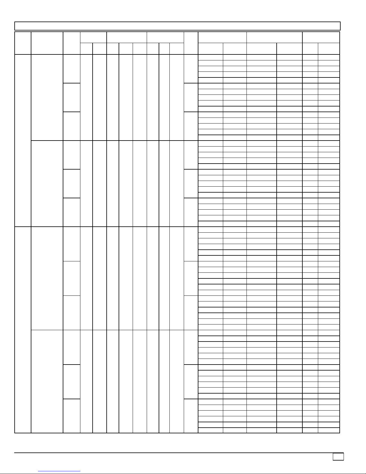
Table 2A -- Electrical Data (Without Convenience Outlet)
PAE
UNIT
SIZE
036
NOMINAL
V-PH-Hz
208/230-3-60
460-3-60
VO LTAGE
RANGE
IFM
Min Max Qty RLA LRA Qty Hp FLA
TYPE
STD
187 254 1 10.2 75 1
ALT 4.9
HIGH 5.2
STD
414 508 1 4.4 40 1
ALT 2.1
HIGH 2.6
COMPRESSOR
(ea)
OFM (ea)
DISCONNECT
SIZE†
IFM
FLA
ELECTRIC HEAT POWER SUPPLY
Nominal
kW
FLA MCA MOCP* FLA LRA
—/— —/— 17.7/17.7 25/25 17/17 85/ 85
3.3/ 4.4 9.2/10.6 17.7/17.7 25/25 17/17 85/ 85
4.9/ 6.5 13.6/15.6 21.3/23.9 25/25 20/22 85/ 85
3.5
6.5/ 8.7 18.1/20.9 27.0/30.5 30/35 25/28 85/ 85
7.9/10.5 21.9/25.3 31.7/35.9 35/40 29/33 85/ 85
12.2/16.0 33.4/38.4 46.1/52.4 50/60 42/48 85/ 85
—/— —/— 19.1/19.1 25/25 19/19 90/ 90
3.3/ 4.4 9.2/10.6 19.1/19.4 25/25 19/19 90/ 90
1/
1.4
4
4.9/ 6.5 13.6/15.6 23.1/25.7 25/30 21/24 90/ 90
6.5/ 8.7 18.1/20.9 28.8/32.3 30/35 26/30 90/ 90
7.9/10.5 21.9/25.3 33.5/37.7 35/40 31/35 90/ 90
12.3/16.0 33.4/38.4 47.8/54.2 50/60 44/50 90/ 90
—/— —/— 19.4/19.4 25/25 19/19 109/109
3.3/ 4.4 9.2/10.6 19.4/19.7 25/25 19/19 109/109
4.9/ 6.5 13.6/15.6 23.4/26.0 30/30 22/24 109/109
6.5/ 8.7 18.1/20.9 29.2/32.7 30/35 27/30 109/109
7.9/10.5 21.9/25.3 33.9/38.1 35/40 31/35 109/109
12.3/16.0 33.4/38.4 48.2/54.6 50/60 44/50 109/109
— — 7.6 15 7 44
6.0 7.2 10.6 15 10 45
1.3
8.8 10.6 14.9 15 14 45
11. 5 13.8 18.9 20 17 45
14.0 16.8 22.7 25 21 45
— — 8.4 15 8 48
6.0 7.2 11.6 15 11 48
1/
0.8
4
8.8 10.6 15.9 20 15 48
11. 5 13.8 19.9 20 18 48
14.0 16.8 23.7 25 22 48
— — 8.9 15 9 57
6.0 7.2 12.3 15 11 57
8.8 10.6 16.5 20 15 57
11. 5 13.8 20.5 25 19 57
14.0 16.8 24.3 25 22 57
10
522 01 1001 01
PAE
UNIT
SIZE
048
060
NOMINAL
V-PH-Hz
208/230-3-60
460-3-60
208/230-3-60
460-3-60
Table 2A -- Electrical Data (Without Convenience Outlet)
VO LTAGE
RANGE
IFM
Min Max Qty RLA LRA Qty Hp FLA
TYPE
STD
187 254 1 15.4 90 1
ALT 4.9
HIGH 5.2
STD
414 508 1 8.3 45 1
ALT 2.1
HIGH 2.6
STD
187 254 1 16 11 4 1
ALT 5.2
HIGH 7.5
STD
414 508 1 7.4 64 1
ALT 2.6
HIGH 3.4
COMPRESSOR
(ea)
OFM (ea)
1/
4
1/
4
1/
4
1/
4
1.4
0.8
1.4
0.8
IFM
FLA
3.5
1.8
5.9
3.1
DISCONNECT
ELECTRIC HEAT POWER SUPPLY
Nominal
kW
FLA MCA MOCP* FLA LRA
SIZE†
—/— —/— 24.2/24.2 30/30 23/23 101/101
4.9/6.5 13.6/15.6 24.2/24.2 30/30 23/23 101/101
6.5/8.7 18.1/20.9 27.0/30.5 30/35 25/28 101/101
12.0/16.0 33.4/38.4 46.1/52.4 50/60 42/48 101/101
15.8/21.0 43.8/50.5 59.1/67.5 60/70** 54/62 101/101
—/— —/— 25.6/25.6 30/30 25/25 105/105
4.9/6.5 13.6/15.6 25.6/25.7 30/30 25/25 105/105
6.5/8.7 18.1/20.9 28.8/32.3 30/35 26/30 105/105
12.0/16.0 33.4/38.4 47.8/54.2 50/60 44/50 105/105
15.8/21.0 43.8/50.5 60.8/69.3 70/70** 56/64 105/105
—/— —/— 25.9/25.9 30/30 25/25 124/124
4.9/6.5 13.6/15.6 25.9/26.0 30/30 25/25 124/124
6.5/8.7 18.1/20.9 29.2/32.7 30/35 27/30 124/124
12.0/16.0 33.4/38.4 48.2/54.6 50/60 44/50 124/124
15.8/21.0 43.8/50.5 61.2/69.6 70/70** 56/64 124/124
— — 13.0 20 13 51
6.0 7.2 13.0 20 13 51
11. 5 13.8 19.5 20 18 51
14.0 16.8 23.3 25 21 51
23.0 27.7 36.8 40 34 51
— — 13.3 20 13 53
6.0 7.2 13.3 20 13 53
11. 5 13.8 19.9 20 18 53
14.0 16.8 23.7 25 22 53
23.0 27.7 37.2 40 34 53
— — 13.8 20 13 62
6.0 7.2 13.8 20 13 62
11. 5 13.8 20.5 25 19 62
14.0 16.8 24.3 25 22 62
23.0 27.7 37.8 40 35 62
—/— —/— 27.3/27.3 35/35 27/27 128/128
4.9/6.5 13.6/15.6 27.3/27.3 35/35 27/27 128/128
7.9/10.5 21.9/25.3 34.7/38.9 40/40 32/36 128/128
12.0/16.0 33.4/38.4 49.1/55.4 50/60 45/51 128/128
15.8/21.0 43.8/50.5 62.1/70.5 70/80** 57/65 128/128
19.9/26.5 55.2/63.8 76.4/87.1 80/90** 70/80 128/128
—/— —/— 26.6/26.6 35/35 26/26 148/148
4.9/6.5 13.6/15.6 26.6/26.6 35/35 26/26 148/148
7.9/10.5 21.9/25.3 33.9/38.1 35/40 31/35 148/148
12.0/16.0 33.4/38.4 48.2/54.6 50/60 44/50 148/148
15.8/21.0 43.8/50.5 61.2/69.6 70/70** 56/64 148/148
19.9/26.5 55.2/63.8 75.6/86.2 80/90** 70/79 148/148
—/— —/— 28.9/28.9 35/35 29/29 174/174
4.9/6.5 13.6/15.6 28.9/28.9 35/35 29/29 174/174
7.9/10.5 21.9/25.3 36.7/40.9 40/45 34/38 174/174
12.0/16.0 33.4/38.4 51.1/57.4 60/60 47/53 174/174
15.8/21.0 43.8/50.5 64.1/72.5 70/80** 59/67 174/174
19.9/26.5 55.2/63.8 78.4/89.1 80/90** 72/82 174/174
— — 13.2 20 13 71
6.0 7.2 13.2 20 13 72
11. 5 13.8 21.2 25 19 72
14.0 16.8 24.9 25 23 72
23.0 27.7 38.5 40 35 72
25.0 30.1 41.5 45 38 72
— — 13.5 20 13 81
6.0 7.2 13.5 20 13 81
11. 5 13.8 21.5 25 20 81
14.0 16.8 25.3 30 23 81
23.0 27.7 38.8 40 36 81
25.0 30.1 41.8 45 38 81
— — 13.5 20 13 93
6.0 7.2 13.5 20 13 94
11. 5 13.8 21.5 25 20 94
14.0 16.8 25.3 30 23 94
23.0 27.7 38.8 40 36 94
25.0 30.1 41.8 45 38 94
522 01 1001 01
11
PAE
UNIT
SIZE
060
072
NOMINAL
V-PH-Hz
208/230-3-60
460-3-60
208/230-3-60
460-3-60
Table 2A -- Electrical Data (Without Convenience Outlet)
VOLT.
RANGE
IFM
Min Max Qty RLA LRA Qty Hp FLA
TYPE
STD
187 254 1 16 114 1
ALT 5.2
HIGH 7.5
STD
414 508 1 7.4 64 1
ALT 2.6
HIGH 3.4
STD
187 254 1 20.6 146 1
HIGH 7.5
STD
414 508 1 9.5 73 1
HIGH 3.4
COMPRESSOR
(ea)
OFM (ea)
1/
4
1/
4
1/
4
1/
4
1.4
0.8
1.4
0.9
IFM
FLA
5.9
3.1
5.2
2.6
DISCONNECT
ELECTRIC HEAT POWER SUPPLY
Nominal
kW
FLA MCA MOCP* FLA LRA
SIZE†
—/— —/— 27.3/27.3 35/35 27/27 128/128
4.9/6.5 13.6/15.6 27.3/27.3 35/35 27/27 128/128
7.9/10.5 21.9/25.3 34.7/38.9 40/40 32/36 128/128
12.0/16.0 33.4/38.4 49.1/55.4 50/60 45/51 128/128
15.8/21.0 43.8/50.5 62.1/70.5 70/80** 57/65 128/128
19.9/26.5 55.2/63.8 76.4/87.1 80/90** 70/80 128/128
—/— —/— 26.6/26.6 35/35 26/26 148/148
4.9/6.5 13.6/15.6 26.6/26.6 35/35 26/26 148/148
7.9/10.5 21.9/25.3 33.9/38.1 35/40 31/35 148/148
12.0/16.0 33.4/38.4 48.2/54.6 50/60 44/50 148/148
15.8/21.0 43.8/50.5 61.2/69.6 70/70** 56/64 148/148
19.9/26.5 55.2/63.8 75.6/86.2 80/90** 70/79 148/148
—/— —/— 28.9/28.9 35/35 29/29 174/174
4.9/6.5 13.6/15.6 28.9/28.9 35/35 29/29 174/174
7.9/10.5 21.9/25.3 36.7/40.9 40/45 34/38 174/174
12.0/16.0 33.4/38.4 51.1/57.4 60/60 47/53 174/174
15.8/21.0 43.8/50.5 64.1/72.5 70/80** 59/67 174/174
19.9/26.5 55.2/63.8 78.4/89.1 80/90** 72/82 174/174
— — 13.2 20 13 71
6.0 7.2 13.2 20 13 72
11. 5 13.8 21.2 25 19 72
14.0 16.8 24.9 25 23 72
23.0 27.7 38.5 40 35 72
25.0 30.1 41.5 45 38 72
— — 13.5 20 13 81
6.0 7.2 13.5 20 13 81
11. 5 13.8 21.5 25 20 81
14.0 16.8 25.3 30 23 81
23.0 27.7 38.8 40 36 81
25.0 30.1 41.8 45 38 81
— — 13.5 20 13 93
6.0 7.2 13.5 20 13 94
11. 5 13.8 21.5 25 20 94
14.0 16.8 25.3 30 23 94
23.0 27.7 38.8 40 36 94
25.0 30.1 41.8 45 38 94
—/— —/— 32.4/32.4 40/40 31/31 180/180
4.9/ 6.5 13.6/15.6 32.4/32.4 40/40 31/31 180/180
7.9/10.5 21.9/25.3 33.9/38.1 35/40 31/35 180/180
12.0/16.0 33.4/38.4 48.2/54.6 50/60 44/50 180/180
15.8/21.0 43.8/50.5 61.2/69.6 70/70** 56/64 180/180
19.9/26.5 55.2/63.8 75.6/86.2 80/90** 70/79 180/180
—/— —/— 34.7/34.7 40/40 34/34 205/205
4.9/ 6.5 13.6/15.6 34.7/34.7 40/40 34/34 205/205
7.9/10.5 21.9/25.3 36.7/40.9 40/45 34/38 205/205
12.0/16.0 33.4/38.4 51.1/57.4 60/60 47/53 205/205
15.8/21.0 43.8/50.5 64.1/72.5 70/80** 59/67 205/205
19.9/26.5 55.2/63.8 78.4/89.1 80/90** 72/82 205/205
— — 15.4 20 15 90
6.0 7.2 15.4 20 15 90
11. 5 13.8 20.5 25 19 90
14.0 16.8 24.3 25 22 90
23.0 27.7 37.8 40 35 90
25.5 30.7 41.6 45 38 90
— — 16.2 20 16 103
6.0 7.2 16.2 20 16 103
11. 5 13.8 21.5 25 20 103
14.0 16.8 25.3 30 23 103
23.0 27.7 38.8 40 36 103
25.5 30.7 42.6 45 39 103
12
522 01 1001 01
PAE NOMINAL IFM
STD
208/230-3-60
ALT 4.9
HIGH 5.2
036
STD
460-3-60
ALT 2.1
HIGH 2.6
STD
208/230-3-60
ALT 4.9
HIGH 5.2
048
STD
460-3-60
ALT 2.1
HIGH 2.6
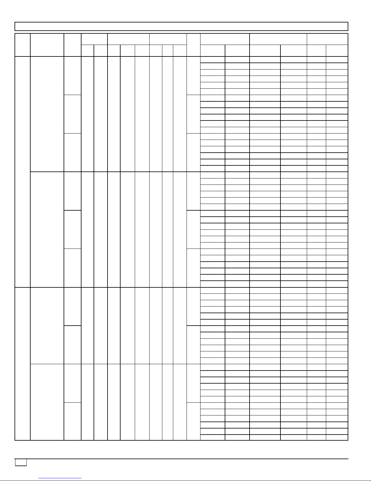
Table 2B -- Electrical Data (With Convenience Outlet)
VO LTAGE
RANGE
Min Max Qty RLA LRA Qty Hp FLA NominalkWFLA MCA MOCP* FLA LRA
187 254 1 10.2 75 1
414 508 1 4.4 40 1
187 254 1 15.4 90 1
414 508 1 8.3 45 1
COMPRESSOR
(ea)
OFM (ea)
1/
4
1/
4
1/
4
1/
4
1.4
0.8
1.4
0.8
ELECTRIC HEAT POWER SUPPLY
DISCONNECT
IFM
—/— —/— 22.5/22.5 30/30 23/23 90/ 90
3.3/ 4.4 9.2/10.6 22.5/23.0 30/30 23/23 90 90
4.9/ 6.5 13.6/15.6 27.3/29.4 30/30 25/28 90/ 90
3.5
6.5/ 8.7 18.1/20.9 33.1/36.0 35/40 30/34 90/ 90
7.9/10.5 21.9/25.3 37.7/42.0 40/45 35/39 90/ 90
12.2/16.0 33.4/38.4 52.1/57.9 60/60 48/54 90/ 90
—/— —/— 23.9/23.9 30/30 25/25 95/ 95
3.3/ 4.4 9.2/10.6 23.9/24.8 30/30 25/25 95/ 95
4.9/ 6.5 13.6/15.6 29.1/31.1 30/35 27/29 95/ 95
6.5/ 8.7 18.1/20.9 34.8/37.7 35/40 32/35 95/ 95
7.9/10.5 21.9/25.3 39.5/43.7 40/45 36/40 95/ 95
12.3/16.0 33.4/38.4 53.8/59.6 60/60 50/55 95/ 95
—/— —/— 24.2/24.2 30/30 25/25 114/114
3.3/ 4.4 9.2/10.6 24.2/25.2 30/30 25/25 114/114
4.9/ 6.5 13.6/15.6 29.5/31.5 35/35 27/29 114/114
6.5/ 8.7 18.1/20.9 35.2/38.1 40/40 32/36 114/114
7.9/10.5 21.9/25.3 39.9/44.1 40/45 37/41 114/114
12.3/16.0 33.4/38.4 54.2/60.0 60/60 50/56 114/114
— — 9.8 15 10 47
6.0 7.2 13.4 15 12 47
1.3
8.8 10.6 17.6 20 16 47
11. 5 13.8 21.6 25 20 47
14.0 16.8 25.4 30 23 47
— — 10.6 15 11 50
6.0 7.2 14.4 15 13 50
8.8 10.6 18.6 20 17 50
11. 5 13.8 22.6 25 21 50
14.0 16.8 26.4 30 24 50
— — 11 .1 15 11 59
6.0 7.2 15.0 20 14 59
8.8 10.6 19.2 20 18 59
11. 5 13.8 23.3 25 21 59
14.0 16.8 27.0 30 25 59
—/— —/— 29.0/29.0 35/35 29/29 106/106
4.9/ 6.5 13.6/15.6 29.0/29.4 35/35 29/29 106/106
3.5
6.5/ 8.7 18.1/20.9 33.1/36.0 35/40 30/34 106/106
12.0/16.0 33.4/38.4 52.1/57.9 60/60 48/54 106/106
15.8/21.0 43.8/50.5 65.1/73.5 70/80**60/68 106/106
—/— —/— 30.4/30.4 35/35 30/30 110/110
4.9/ 6.5 13.6/15.6 30.4/31.1 35/35 30/30 110/110
6.5/ 8.7 18.1/20.9 34.8/37.7 35/40 32/35 110/110
12.0/16.0 33.4/38.4 53.8/59.6 60/60 50/55 110/110
15.8/21.0 43.8/50.5 66.9/75.3 70/80**62/69 110/110
—/— —/— 30.7/30.7 35/35 31/31 129/129
4.9/ 6.5 13.6/15.6 30.7/31.5 35/35 31/31 129/129
6.5/ 8.7 18.1/20.9 35.2/38.1 40/40 32/36 129/129
12.0/16.0 33.4/38.4 54.2/60.0 60/60 50/56 129/129
15.8/21.0 43.8/50.5 67.2/75.7 70/80**62/70 129/129
— — 15.2 20 15 53
6.0 7.2 15.2 20 15 53
1.8
11. 5 13.8 22.3 25 20 53
14.0 16.8 26.0 30 24 53
23.0 27.7 39.6 40 36 53
— — 15.5 20 15 55
6.0 7.2 15.5 20 15 55
11. 5 13.8 22.6 25 21 55
14.0 16.8 26.4 30 24 55
23.0 27.7 39.9 40 37 55
— — 16.0 20 16 64
6.0 7.2 16.0 20 16 64
11. 5 13.8 23.3 25 21 64
14.0 16.8 27.0 30 25 64
23.0 27.7 40.6 45 37 64
SIZE†
522 01 1001 01
13
PAE NOMINAL IFM
STD
208/230-3-60
ALT 5.2
HIGH 7.5
060
STD
460-3-60
ALT 2.6
HIGH 3.4
STD
208/230-3-60
HIGH 7.5
072
STD
460-3-60
HIGH 3.4
Table 2B -- Electrical Data (With Convenience Outlet)
VO LTAGE
RANGE
Min Max Qty RLA LRA Qty Hp FLA NominalkWFLA MCA MOCP* FLA LRA
187 254 1 16 114 1
414 508 1 7.4 64 1
187 254 1 20.6 146 1
414 508 1 9.5 73 1
COMPRESSOR
(ea)
OFM (ea)
1/
4
1/
4
1/
4
1/
4
1.4
0.8
1.4
0.9
ELECTRIC HEAT POWER SUPPLY
DISCONNECT
IFM
—/— —/— 32.1/32.1 40/40 32/32 133/133
4.9/6.5 13.6/15.6 32.1/32.4 40/40 32/32 133/133
7.9/10.5 21.9/25.3 40.7/44.4 45/45 37/41 133/133
5.9
12.0/16.0 33.4/38.4 55.1/60.9 60/70** 51/57 133/133
15.8/21.0 43.8/50.5 68.1/76.5 70/80** 63/70 133/133
19.9/26.5 55.2/63.8 82.4/92.5 90/00** 76/86 133/133
—/— —/— 31.4/31.4 40/40 32/32 153/153
4.9/6.5 13.6/15.6 31.4/31.5 40/40 32/32 153/153
7.9/10.5 21.9/25.3 39.9/43.5 40/45 37/41 153/153
12.0/16.0 33.4/38.4 54.2/60.0 60/60 50/56 153/153
15.8/21.0 43.8/50.5 67.2/75.7 70/80** 62/70 153/153
19.9/26.5 55.2/63.8 81.6/91.6 90/00** 75/85 153/153
—/— —/— 33.7/33.7 40/40 34/34 179/179
4.9/6.5 13.6/15.6 33.7/34.4 40/40 34/34 179/179
7.9/10.5 21.9/25.3 42.7/46.4 45/50 39/43 179/179
12.0/16.0 33.4/38.4 57.1/62.9 60/70** 53/58 179/179
15.8/21.0 43.8/50.5 70.1/78.5 80/80** 65/72 179/179
19.9/26.5 55.2/63.8 84.4/94.5 90/00** 78/87 179/179
— — 15.3 20 15 74
6.0 7.2 15.6 20 15 74
3.1
11. 5 13.8 23.9 25 22 74
14.0 16.8 27.6 30 25 74
23.0 27.7 41.2 45 38 74
25.0 30.1 44.2 45 41 74
— — 15.6 20 16 83
6.0 7.2 16.0 20 16 83
11. 5 13.8 24.3 25 22 83
14.0 16.8 28.0 30 26 83
23.0 27.7 41.6 45 38 83
25.0 30.1 44.6 45 41 83
— — 15.6 20 16 96
6.0 7.2 16.0 20 16 96
11. 5 13.8 24.3 25 22 96
14.0 16.8 28.0 30 26 96
23.0 27.7 41.6 45 38 96
25.0 30.1 44.6 45 41 96
—/— —/— 37.2/37.2 45/ 45 37/37 184/184
4.9/ 6.5 13.6/15.6 37.2/37.2 45/ 45 37/37 184/184
7.9/10.5 21.9/25.3 37.2/38.1 40/ 45 37/41 184/184
5.2
12.0/16.0 33.4/38.4 54.2/60.0 60/ 60 50/56 184/184
15.8/21.0 43.8/50.5 67.2/75.7 70/ 80** 62/70 184/184
19.9/26.5 55.2/63.8 81.6/91.6 90/100** 75/85 184/184
—/— —/— 39.5/39.5 45/ 45 39/39 210/210
4.9/ 6.5 13.6/15.6 39.5/39.5 45/ 45 39/39 210/210
7.9/10.5 21.9/25.3 39.5/40.9 45/ 50 39/43 210/210
12.0/16.0 33.4/38.4 57.1/62.9 60/ 70** 53/58 210/210
15.8/21.0 43.8/50.5 70.1/78.5 80/ 80** 65/72 210/210
19.9/26.5 55.2/63.8 84.4/94.5 90/100** 78/87 210/210
— — 17.6 20 17 92
6.0 7.2 17.6 20 17 92
2.6
11. 5 13.8 20.5 25 21 92
14.0 16.8 27.0 30 25 92
23.0 27.7 40.6 45 37 92
25.5 30.7 44.3 45 41 92
— — 18.4 25 18 105
6.0 7.2 18.4 25 18 105
11. 5 13.8 21.5 25 22 105
14.0 16.8 28.0 30 26 105
23.0 27.7 41.6 45 38 105
25.5 30.7 45.3 50 42 105
SIZE†
14
522 01 1001 01
LEGENDS AND NOTES
Legend
FLA — Full Load Amps
HACR — Heating, Air Conditioning and Refrigeration
IFM — Indoor (Evaporator) Fan Motor
LRA — Locked Rotor Amps
MCA — Minimum Circuit Amps
MOCP — Maximum Overcurrent Protection
NEC — National Electrical Code
OFM — Outdoor (Condenser) Fan Motor
RLA — Rated Load Amps
*Used to determine minimum disconnect per NEC.
[Fuse or HACR circuit breaker.
NOTES
: 1. In compliance with NEC requirements for multimotor and combination load
equipment (refer to NEC Articles 430 and 440), the overcurrent protective device for the
unit shall be fuse or HACR breaker. Canadian units may be fuse or circuit breaker.
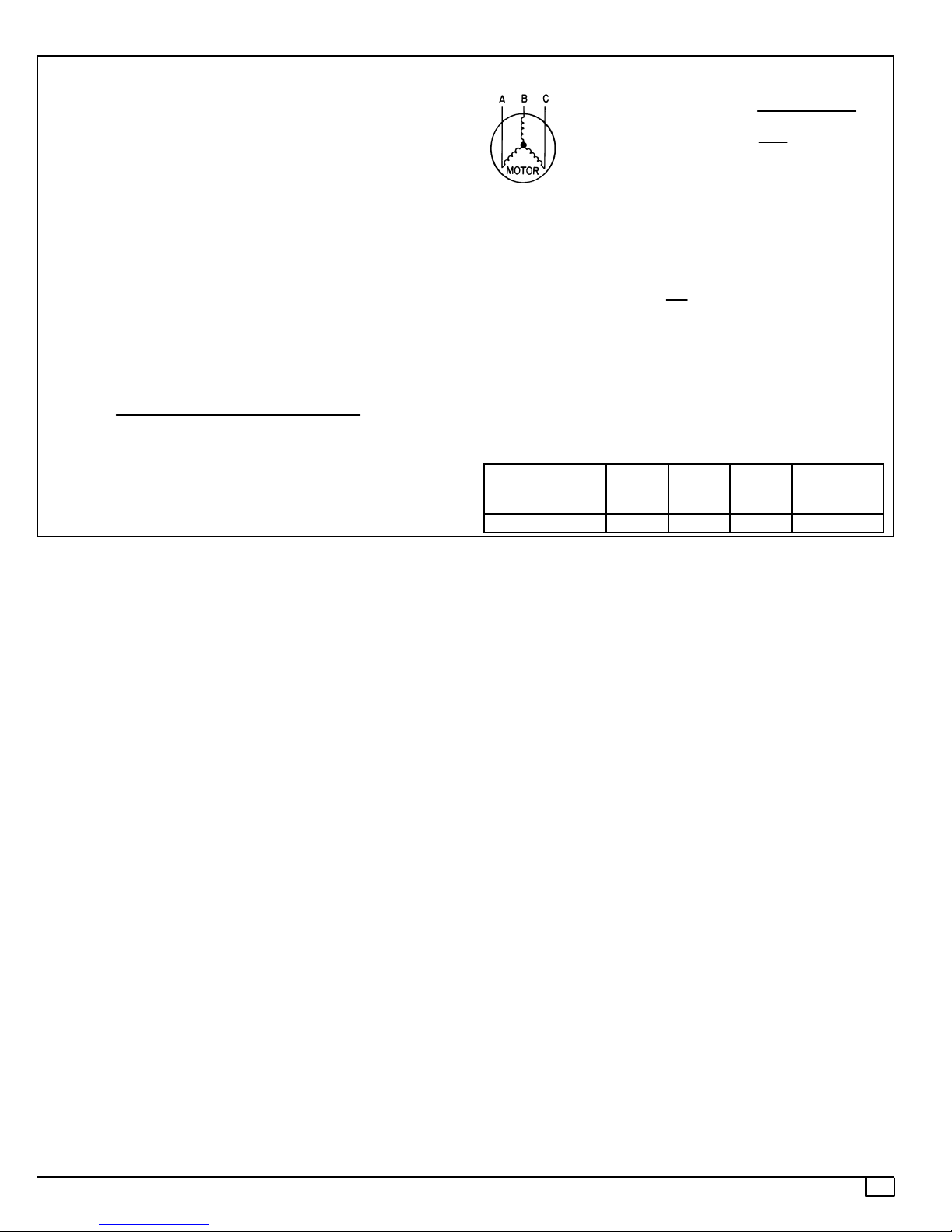
2. Unbalanced 3- Phase Supply Voltage Never operate a motor where a phase
imbalance in supply voltage is greater than 2%. Use the following formula to determine
the percent of
% Voltage Imbalance
= 100 x
max voltage deviation from average
average voltage
voltage
N
EXAMPLE: Supply voltage is
AB = 452 v
BC = 464 v
AC = 455 v
Determine maximum deviation from average voltage.
460--3--60.
Average Voltage =
452 + 464 +
1371
=
3
= 457
(AB) 457 -- 452 = 5 V
(BC) 464 -- 457 = 7 V
(AB) 457 -- 455 = 2 V
Maximum deviation is 7 v.
Determine percent voltage imbalance.
7
% Voltage Imbalance = 100 x
This amount of phase imbalance is satisfactory as it is below the
maximum allowable 2%.
IMPORTANT : If the supply voltage phase imbalance is more than
2%, contact your local electric utility company immediately .
457
= 1.53%
3. power exhaust MCA and MOCP. Check MCA and MOCP when
power exhaust is powered through the unit (must be in accordance
with NEC and/or local codes). Determine the new MCA including the
power exhaust using the following formula:
MCA New = MCA unit only + MCA of Power Exhaust
POWER EXHAUST
PART NO.
MCA
(230 v)
MCA
(460 v)
MCA
(575 v)
DNPWREXH021A01 N/A 0.9 N/A 15
455
3
MOCP (for
separate
power source)
522 01 1001 01
15
 Loading...