

Page 1

5900 SERIES Mobile Mount Radio Data Terminal
USER’S GUIDE
" " " " " " " " " " " " " " " " " " " " " " " " " " " "
PN: 961-047-121
Revision A
August 1998
Page 2

" NOTICE This publication is furnished for information only,and the information in it is subject tochange
without notice. Although every effort has been made to provide complete and accurate
information, Norand Corporation assumes no responsibility or liability for any errors or
inaccuracies that may appear in this document.
Wewelcome your comments concerning this publication. Although every effort has been made
to keep it free of errors, some may occur.When reporting a specific problem, please describe it
briefly and include the book title and part number, as well as the paragraph or figure number
and the page number.
Send your comments to:
Publications Department
Intermec TechnologiesCorporation
550 Second Street SE
Cedar Rapids, IA 52401
Telephone(319) 369-3100
Faxsimile (319) 369-3453
ä
Ò
Trademark, Norand Corporation, Cedar Rapids, Iowa, U.S.A.
Ó Copyright 1994 Norand Corporation. All rights reserved.
This publication printed on recycled paper.
FCC Computer Compliance
" NOTICE This equipment meets Class A digital device limits per Part 15 of FCC Rules. These limits
protect against interference in a commercial area. Itemits, uses, and can radiate radio
frequency energy. If you do not install and use the equipment according to its instructions, it
may interfere with radio signals. Using it in a residential area is likely to cause interference. If
this occurs, you must correct the interference at your expense.
If this equipment does cause harmful interference to radio or television reception, which canbe
determined by turning our equipment off and on, the user is encouraged to try to correct the
interference by one or more of the following measures:
" Reorient or relocate the radio or television receiving antenna.
" Increase the separation between the computer equipment and receiver.
" Connect the equipment into an outlet on a circuit different from that to which the
radio or television receiver is connected.
" Consult the dealer or an experienced radio or television technician for help.
Page 3

CONTENTS "
CONTENTS
" " " " " " " " " " " " " " " " " " " " " " " " " " " "
SECTION 1
User Information
About this Manual 1-1. . . . . . . . . . . . . . . . . . . . . . . . . . . . . . . . . . . . . . . . . .
Section One 1-1. . . . . . . . . . . . . . . . . . . . . . . . . . . . . . . . . . . . . . . . . . . .
Section Two 1-1. . . . . . . . . . . . . . . . . . . . . . . . . . . . . . . . . . . . . . . . . . .
Section Three 1-1. . . . . . . . . . . . . . . . . . . . . . . . . . . . . . . . . . . . . . . . . .
General Information 1-2. . . . . . . . . . . . . . . . . . . . . . . . . . . . . . . . . . . . . . . . .
Installation 1-2. . . . . . . . . . . . . . . . . . . . . . . . . . . . . . . . . . . . . . . . . . . .
Keyboard 1-2. . . . . . . . . . . . . . . . . . . . . . . . . . . . . . . . . . . . . . . . . . . . . .
How it Works 1-2. . . . . . . . . . . . . . . . . . . . . . . . . . . . . . . . . . . . . . . . . .
The Terminal 1-3. . . . . . . . . . . . . . . . . . . . . . . . . . . . . . . . . . . . . . . . . . . . . . .
On/Off Switch 1-4. . . . . . . . . . . . . . . . . . . . . . . . . . . . . . . . . . . . . . . . . .
The Display 1-4. . . . . . . . . . . . . . . . . . . . . . . . . . . . . . . . . . . . . . . . . . . .
Status Indicators 1-5. . . . . . . . . . . . . . . . . . . . . . . . . . . . . . . . . . . . . . . .
The Keyboard 1-5.. . . . . . . . . . . . . . . . . . . . . . . . . . . . . . . . . . . . . . . . .
Number Keys 1-5. . . . . . . . . . . . . . . . . . . . . . . . . . . . . . . . . . . . . .
Function Keys 1-5. . . . . . . . . . . . . . . . . . . . . . . . . . . . . . . . . . . . . .
Miscellaneous Keys 1-6. . . . . . . . . . . . . . . . . . . . . . . . . . . . . . . . .
Maintenance 1-7. . . . . . . . . . . . . . . . . . . . . . . . . . . . . . . . . . . . . . . . . . . . . . .
Cleaning 1-7. . . . . . . . . . . . . . . . . . . . . . . . . . . . . . . . . . . . . . . . . . . . . .
Daily Checks 1-7. . . . . . . . . . . . . . . . . . . . . . . . . . . . . . . . . . . . . . . . . . .
Factory Service 1-8. . . . . . . . . . . . . . . . . . . . . . . . . . . . . . . . . . . . . . . . . . . . .
Product Service Data Card 1-8. . . . . . . . . . . . . . . . . . . . . . . . . . . . . . . .
SECTION 2
Installation Instructions
ToolsRequired for Installation 2-2. . . . . . . . . . . . . . . . . . . . . . . . . . . . . . . . .
Introduction 2-3. . . . . . . . . . . . . . . . . . . . . . . . . . . . . . . . . . . . . . . . . . . . . . .
Power Cable Routing 2-4. . . . . . . . . . . . . . . . . . . . . . . . . . . . . . . . . . . . . . . .
RT5900 SERIES Mobile Mount Radio Data Terminal i
Page 4

CONTENTS "
Power Cable Assembly 2-6. . . . . . . . . . . . . . . . . . . . . . . . . . . . . . . . . . . . . . .
Assembling the In-line Fuse Holder 2-6. . . . . . . . . . . . . . . . . . . . . . . . .
TerminatingWireEnds 2-8. . . . . . . . . . . . . . . . . . . . . . . . . . . . . . . . . . .
Side Mount Battery Connection 2-9. . . . . . . . . . . . . . . . . . . . . . . . . . . .
Power Cable Connection 2-10. . . . . . . . . . . . . . . . . . . . . . . . . . . . . . . . . .
TopMount Battery Connection 2-10. . . . . . . . . . . . . . . . . . . . . . . . . . . .
Secure the Power Cable 2-10.. . . . . . . . . . . . . . . . . . . . . . . . . . . . . . . . .
Mounting the Terminal 2-11. . . . . . . . . . . . . . . . . . . . . . . . . . . . . . . . . . .
Connections to the Terminal 2-12. . . . . . . . . . . . . . . . . . . . . . . . . . . . . . .
ON/OFF button 2-12. . . . . . . . . . . . . . . . . . . . . . . . . . . . . . . . . . . . . . . . .
Desktop Installation Kit Instructions 2-13.. . . . . . . . . . . . . . . . . . . . . . . . . . .
Kit Description 2-13. . . . . . . . . . . . . . . . . . . . . . . . . . . . . . . . . . . . . . . . .
Instructions 2-14. . . . . . . . . . . . . . . . . . . . . . . . . . . . . . . . . . . . . . . . . . . . . . . .
Mounting Bracket 2-14. . . . . . . . . . . . . . . . . . . . . . . . . . . . . . . . . . . . . . .
NC4000 Power Supply 2-14. . . . . . . . . . . . . . . . . . . . . . . . . . . . . . . . . . .
Connect the DC Power Cable 2-14. . . . . . . . . . . . . . . . . . . . . . . . . . . . . .
Connect the AC Power Cable 2-14. . . . . . . . . . . . . . . . . . . . . . . . . . . . . .
SECTION 3
User Interface Instructions
Introduction 3-1. . . . . . . . . . . . . . . . . . . . . . . . . . . . . . . . . . . . . . . . . . . . . . .
Conventions 3-1. . . . . . . . . . . . . . . . . . . . . . . . . . . . . . . . . . . . . . . . . . .
The Keyboard 3-2.. . . . . . . . . . . . . . . . . . . . . . . . . . . . . . . . . . . . . . . . .
Accessing the Menu 3-2. . . . . . . . . . . . . . . . . . . . . . . . . . . . . . . . .
ENTER key 3-2. . . . . . . . . . . . . . . . . . . . . . . . . . . . . . . . . . . . . . . .
1 (or 2, 3, 4, 5, etc) 3-2. . . . . . . . . . . . . . . . . . . . . . . . . . . . . . . . . .
UP arrow and DOWN arrow 3-2. . . . . . . . . . . . . . . . . . . . . . . . . . .
Entry Errors 3-2. . . . . . . . . . . . . . . . . . . . . . . . . . . . . . . . . . . . . . . .
Right Shift/Space 3-3. . . . . . . . . . . . . . . . . . . . . . . . . . . . . . . . . . .
Main Menu 3-4. . . . . . . . . . . . . . . . . . . . . . . . . . . . . . . . . . . . . . . . . . . . . . . .
Exit Menus 3-4. . . . . . . . . . . . . . . . . . . . . . . . . . . . . . . . . . . . . . . . . . . .
Main Menu 3-6. . . . . . . . . . . . . . . . . . . . . . . . . . . . . . . . . . . . . . . . . . . . . . . .
Set Parameters 3-6. . . . . . . . . . . . . . . . . . . . . . . . . . . . . . . . . . . . . . . . . .
Radio # 3-6.. . . . . . . . . . . . . . . . . . . . . . . . . . . . . . . . . . . . . . . . . .
Barcode Parms 3-6. . . . . . . . . . . . . . . . . . . . . . . . . . . . . . . . . . . . .
Advanced Setup (Radio #) 3-8. . . . . . . . . . . . . . . . . . . . . . . . . . . . . . . .
Host A 3-8. . . . . . . . . . . . . . . . . . . . . . . . . . . . . . . . . . . . . . . . . . . . . . . .
Barcode Parms (continued) 3-8. . . . . . . . . . . . . . . . . . . . . . . . . . . .
Scanner Type 3-10. . . . . . . . . . . . . . . . . . . . . . . . . . . . . . . . . . . . . . .
ii RT5900 SERIES Mobile Mount Radio Data Terminal
Page 5

CONTENTS "
Scan Options 3-10. . . . . . . . . . . . . . . . . . . . . . . . . . . . . . . . . . . . . . .
Scan Options [1] 3-12. . . . . . . . . . . . . . . . . . . . . . . . . . . . . . . . . . . .
Scan Options [2] 3-12. . . . . . . . . . . . . . . . . . . . . . . . . . . . . . . . . . . .
Other Scan Options [1] & [2] 3-14. . . . . . . . . . . . . . . . . . . . . . . . . .
Lengths Options 3-14.. . . . . . . . . . . . . . . . . . . . . . . . . . . . . . . . . . .
Protocol Options 3 -16. . . . . . . . . . . . . . . . . . . . . . . . . . . . . . . . . . . . . . . .
Host View Size 3-16. . . . . . . . . . . . . . . . . . . . . . . . . . . . . . . . . . . . .
Data Stream 3-16. . . . . . . . . . . . . . . . . . . . . . . . . . . . . . . . . . . . . . . .
Extended (5250) CMDS 3-16. . . . . . . . . . . . . . . . . . . . . . . . . . . . . .
VT220/3270/5250 Options 3-16. . . . . . . . . . . . . . . . . . . . . . . . . . . .
Display Options 3-18.. . . . . . . . . . . . . . . . . . . . . . . . . . . . . . . . . . . . . . .
Cursor Mode 3-18. . . . . . . . . . . . . . . . . . . . . . . . . . . . . . . . . . . . . . .
Cold Start (not shown) 3-18. . . . . . . . . . . . . . . . . . . . . . . . . . . . . . . . . . .
Radio Comm 3-18. . . . . . . . . . . . . . . . . . . . . . . . . . . . . . . . . . . . . . . . . . .
Protocol 3-19. . . . . . . . . . . . . . . . . . . . . . . . . . . . . . . . . . . . . . . . . . . . . . .
Baud Rate 3-19. . . . . . . . . . . . . . . . . . . . . . . . . . . . . . . . . . . . . . . . . . . . .
Main Menu 3-20. . . . . . . . . . . . . . . . . . . . . . . . . . . . . . . . . . . . . . . . . . . . . . . .
LCD Parms 3-20. . . . . . . . . . . . . . . . . . . . . . . . . . . . . . . . . . . . . . . . . . . .
Contrast 3-20. . . . . . . . . . . . . . . . . . . . . . . . . . . . . . . . . . . . . . . . . . .
Select Size 3-20. . . . . . . . . . . . . . . . . . . . . . . . . . . . . . . . . . . . . . . . .
Screen Mode 3 -20. . . . . . . . . . . . . . . . . . . . . . . . . . . . . . . . . . . . . . .
Key Uppercase 3-20. . . . . . . . . . . . . . . . . . . . . . . . . . . . . . . . . . . . .
Display Annunciators 3-22. . . . . . . . . . . . . . . . . . . . . . . . . . . . . . . . . . . .
Main Menu 3-24. . . . . . . . . . . . . . . . . . . . . . . . . . . . . . . . . . . . . . . . . . . . . . . .
Beeper Setup 3-24. . . . . . . . . . . . . . . . . . . . . . . . . . . . . . . . . . . . . . . . . . .
Key Click 3-24. . . . . . . . . . . . . . . . . . . . . . . . . . . . . . . . . . . . . . . . .
Error Tone 3-24. . . . . . . . . . . . . . . . . . . . . . . . . . . . . . . . . . . . . . . . .
Main Menu 3-26. . . . . . . . . . . . . . . . . . . . . . . . . . . . . . . . . . . . . . . . . . . . . . . .
Tests 3-26. . . . . . . . . . . . . . . . . . . . . . . . . . . . . . . . . . . . . . . . . . . . . . . . .
Peripherals (see Peripherals menu) 3-26. . . . . . . . . . . . . . . . . . . . . .
Converters 3-26. . . . . . . . . . . . . . . . . . . . . . . . . . . . . . . . . . . . . . . . .
Memory View 3-26. . . . . . . . . . . . . . . . . . . . . . . . . . . . . . . . . . . . . .
Packet Driver 3-26. . . . . . . . . . . . . . . . . . . . . . . . . . . . . . . . . . . . . .
Numbers 3-26. . . . . . . . . . . . . . . . . . . . . . . . . . . . . . . . . . . . . . . . . .
Peripherals Menu 3-28. . . . . . . . . . . . . . . . . . . . . . . . . . . . . . . . . . . . . . .
Radio Tests 3-28. . . . . . . . . . . . . . . . . . . . . . . . . . . . . . . . . . . . . . . .
RS Loop 3-28. . . . . . . . . . . . . . . . . . . . . . . . . . . . . . . . . . . . . . . . . .
LCD Display 3-28. . . . . . . . . . . . . . . . . . . . . . . . . . . . . . . . . . . . . . .
Keyboard 3-28. . . . . . . . . . . . . . . . . . . . . . . . . . . . . . . . . . . . . . . . . .
Scanner 3-28.. . . . . . . . . . . . . . . . . . . . . . . . . . . . . . . . . . . . . . . . . .
RT5900 SERIES Mobile Mount Radio Data Terminal iii
Page 6

CONTENTS "
Main Menu 3-30. . . . . . . . . . . . . . . . . . . . . . . . . . . . . . . . . . . . . . . . . . . . . . . .
Version Info 3-30. . . . . . . . . . . . . . . . . . . . . . . . . . . . . . . . . . . . . . . . . . .
Main Menu 3-31. . . . . . . . . . . . . . . . . . . . . . . . . . . . . . . . . . . . . . . . . . . . . . . .
Exit Menus 3-31.. . . . . . . . . . . . . . . . . . . . . . . . . . . . . . . . . . . . . . . . . . .
More 3-31. . . . . . . . . . . . . . . . . . . . . . . . . . . . . . . . . . . . . . . . . . . . . . . . . . . . .
Keyboard Opts 3-31. . . . . . . . . . . . . . . . . . . . . . . . . . . . . . . . . . . . . . . . .
Save Parms 3-31. . . . . . . . . . . . . . . . . . . . . . . . . . . . . . . . . . . . . . . . . . . .
Cloning Opts 3-31. . . . . . . . . . . . . . . . . . . . . . . . . . . . . . . . . . . . . . . . . . .
Session Menu 3-33. . . . . . . . . . . . . . . . . . . . . . . . . . . . . . . . . . . . . . . . . .
FIGURES
Figure 1-1 Terminal Rear View 1-3. . . . . . . . . . . . . . . . . . . . . . . . . . . . . . . .
Figure 1-2 Terminal Front View 1-4. . . . . . . . . . . . . . . . . . . . . . . . . . . . . . . .
Figure 1-3 Received Signal Strength Indicator 1-7. . . . . . . . . . . . . . . . . . . . .
Figure 2-1 Parts Identification 2-2. . . . . . . . . . . . . . . . . . . . . . . . . . . . . . . . .
Figure 2-2 Stripping the Power Cable Jacket 2-5. . . . . . . . . . . . . . . . . . . . . .
Figure 2-3 Assembling the In--Line Fuse Holder 2-7. . . . . . . . . . . . . . . . . . .
Figure 2-4 Terminating Wire Ends 2-8. . . . . . . . . . . . . . . . . . . . . . . . . . . . . .
Figure 2-5 Side Mount Battery 2-9. . . . . . . . . . . . . . . . . . . . . . . . . . . . . . . . .
Figure 2-6 Top Mount Battery 2-10. . . . . . . . . . . . . . . . . . . . . . . . . . . . . . . . .
Figure 2-7 Mounting the Terminal 2-11. . . . . . . . . . . . . . . . . . . . . . . . . . . . . .
Figure 2-8 Cable Connections 2-12. . . . . . . . . . . . . . . . . . . . . . . . . . . . . . . . .
Figure 2-9 The NC4000 Power Supply 2-15.. . . . . . . . . . . . . . . . . . . . . . . . .
TABLES
Table1-1 Specifications 1-9. . . . . . . . . . . . . . . . . . . . . . . . . . . . . . . . . . . . . .
Table2-1 Parts List kit NPN: 203-300-006 2-1. . . . . . . . . . . . . . . . . . . . . . .
Table2-2 Parts List kit NPN: 203-300-004 2-13. . . . . . . . . . . . . . . . . . . . . . .
Table3-1 Firmware Table 3-30. . . . . . . . . . . . . . . . . . . . . . . . . . . . . . . . . . . . .
iv RT5900 SERIES Mobile Mount Radio Data Terminal
Page 7

Section 1
User Information
" " " " " " " " " " " " " " " " " " " " " " " " " " " "
About this Manual
This User’s Guide contains a product introduction and General Information
(Section One ), Installation Instructions (Section Two), and User Interface
information (Section Three).
Section One
The General Information section is most useful to the end user. It describes
the ON/OFF switch, cable connections, the display,and the keyboard.
Detailed operating instructions are not included in this manual because these
will vary with your company’sapplication program and host computer system.
Section Two
The Installation Instructions are intended for the installation technician.
Section Two contains a parts list and illustrated instructions for installing
the power cable and for mounting the radio data terminal.
Section Three
The User Interface section is intended primarily for the system programmer,
but also contains information useful to the end user. The user interface consists of the keyboard, the display, and the menus to customize terminal functions.
RT5900 SERIES Mobile Mount Radio Data Terminal 1-1
Page 8

SECTION 1 " General Information
General Information
The Mobile Mount Radio Data Terminal is a powerful real-time data collection computer for warehouse and automated material handling environments. The computer electronics, radio module, power converter, keyboard,
and the large display are all housed within a single metal container that is
designed to meet NEMA-3 standards.
Installation
Installs easily on motorized load handling equipment such as a forklift
truck. Then, adding a few command codes to your existing software is all
that is needed to get the system up and running in your operation.
Keyboard
The alphanumeric keyboard has extra large keys for use when wearing
gloves, while the large, back-lighted display is visible from a distance under
varied lighting conditions.
How it Works
Radio Data Terminals are often referred to as real-time devices. Whenyou
enter data into the unit, the radio module transmits that information (or your
request for information) immediately to a base unit. From there, the information goes directly to a host computer. If the entry was a request for
information, the host computer transmits it back to the Radio Data Terminal
that made the request.
Real time processing assures that the most current and accurate information
is available to the host computer and to all mobile units.
1-2 RT5900 SERIES Mobile Mount Radio Data Terminal
Page 9
The Terminal
SECTION 1 " General Information
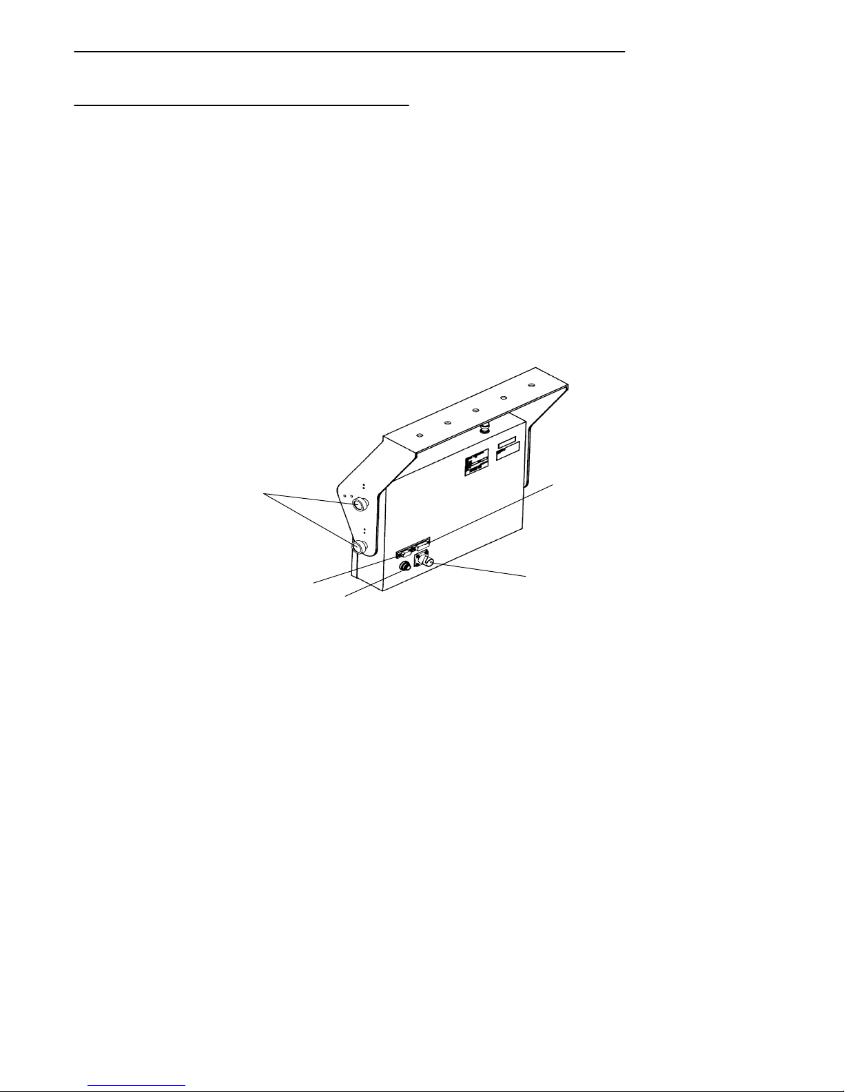
The illustrations in Figure 1-1 and Figure 1-2 will familiarize you with the
external features of the Mobile Mount Radio Data Terminal. Each work day
you should check to make sure that:
" The antenna connector is secure.
" All mounting knobs are tight.
" The power cable is secure.
" The scanner cable is secure.
" The RS-232 communication cable (if so equipped) is secure.
5
4
3
1. RS-232 connector
2. Power connector
3. On/Off switch
4. Scanner connector
5. Mounting knobs
1
2
Figure 1-1
Terminal Rear View
RT5900 SERIES Mobile Mount Radio Data Terminal 1-3
Page 10
SECTION 1 " General Information
On/Off Switch
This is a push-push type switch located on the rear of the unit next to the
power connector. Press the switch once to turn the unit ON. Press the
switch a second time to turn the unit OFF. When the unit is turned ON, the
backlight comes on and a message appears on the display.
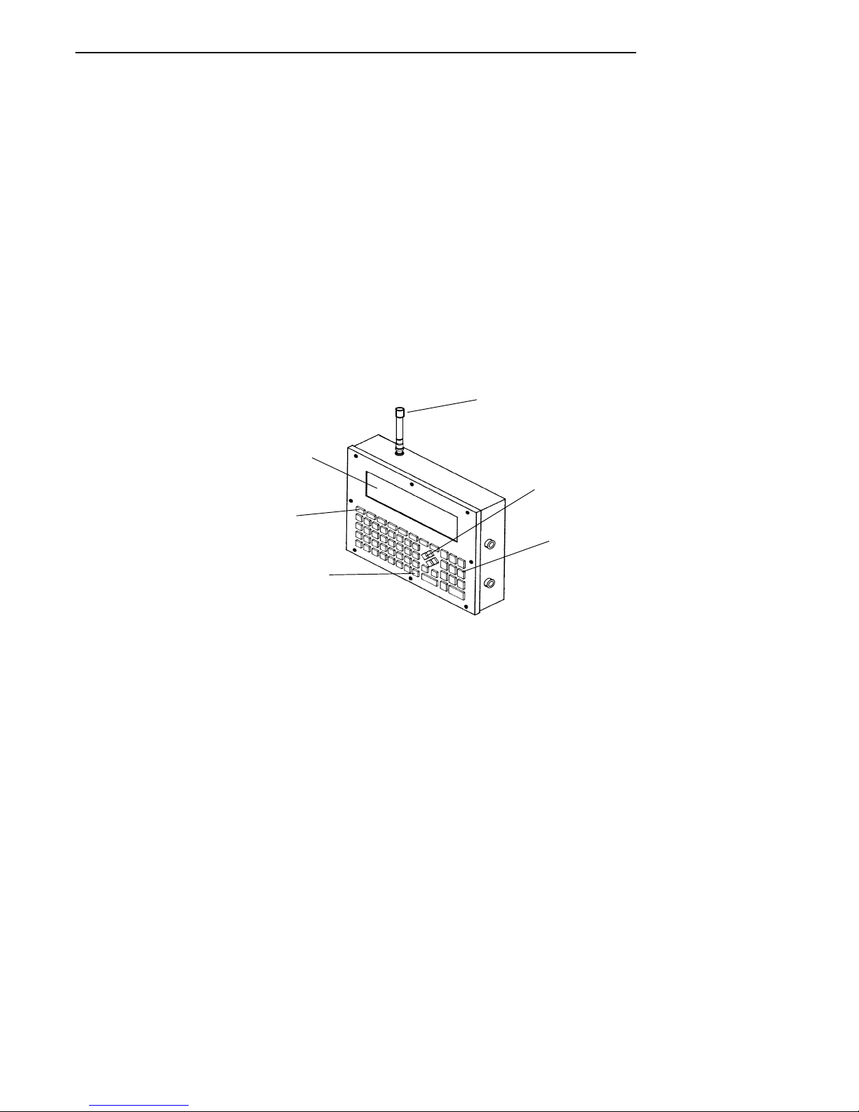
The Display
The display shows current information such as your most recent scan or
manual entry and certain information received from the host computer.
User Interface menus and selections are also shown on the display whenever the operating system must be customized. A keyboard adjustable (see
User Interface, Section 3 of this manual) backlight improves visibility of the
display.
1
6
5
4
1. Antenna
2. Cursor (arrow) keys
3. Numeric keys
4. Miscellaneous keys
5. Function keys
6. Display
Terminal Front View
1-4 RT5900 SERIES Mobile Mount Radio Data Terminal
2
3
Figure 1-2
Page 11

SECTION 1 " General Information
Status Indicators
The display also shows a group of status indicators (icons). Their location
on the display can be changed through the User Interface menus. These
status indicators tell you:
" cursor location by row and column number:
01,02 = row 1, column 2
" whether transmitting or receiving:
transmit = arrow pointing away from radio
receiving = arrow pointing toward radio
" keyboard lockout:
a large X = keyboard lockout ENABLED
(host computer is preventing
the keyboard from working)
The Keyboard
The keyboard has 58 keys that can produce up to 32 different functions.
This is not as complicated as it sounds. For instance, there are 26 alphabet
keys that combine with the SHIFT key to produce upper and lower case letters.
Number Keys
There are ten number (or “numeric”) keys arranged in a familiar ten-key
format. Four cursor movement keys (right, left, up, down) are arranged in a
diamond pattern next to the number keys.
Function Keys
Across the top of the keyboard are eight function keys (F-1 thru F-8). The
function keys can be expanded by the use of the left shift and the right shift
keys which are the two keys located below the cursor keys. These shift
keys are color-coded to correspond with the functions that are printed to the
left or right above each of the F-keys. Thus the left shift key expands the
function keys to F-9 thru F-16, while the right shift key expands the functions to F-17 thru F-24.
RT5900 SERIES Mobile Mount Radio Data Terminal 1-5
Page 12

SECTION 1 " General Information
Miscellaneous Keys
The key with the left-pointing arrow serves as a DELETE key, which eliminates one character to the left each time you press it.
Use the SHIFT key to produce uppercase letters.
The two keys above the SHIFT key have their functions printed above each
key,and to the right of each key. The function to the right of each key is its
unshifted value while the designation above each key is its shifted (use a
SHIFT key) value.
1-6 RT5900 SERIES Mobile Mount Radio Data Terminal
Page 13

Maintenance
SECTION 1 " General Information
Your terminal requires very little maintenance. Clean the terminal and the
display periodically,and perform the daily checks listed below. If a failure
message appears on the display,the Radio Data Terminalmay need to be
sent to an authorized service facility for repair or adjustment. Contact your
authorized service representative for further instructions.
Cleaning
A recommended cleaner for the exterior of the Mobile Mount Radio Data
Terminal is MICRO-CLEAN II cleaner, made by Foresight International,
Inc., 4887 F Street, Omaha, Nebraska 68127-0205 (phone:
1-800-637-1344).
Use a soft, lint-free cloth dampened with a quality glass cleaner to clean the
display area.
Daily Checks
Each work day you should check to make sure that:
" The antenna connector is secure.
" All mounting knobs are tight.
" The power cable is secure.
" The scanner cable is secure.
" The RS-232 communication cable (if so equipped) is secure.
RT5900 SERIES Mobile Mount Radio Data Terminal 1-7
Page 14

SECTION 1 " General Information
Factory Service
When products must be shipped for repair:
" Package in original shipping carton if possible.
" Fill out a Product Service Information Card and include this card
with the product.
If the original shipping container is not available, appropriate packaging
materials can be substituted. If in doubt, contact your authorized service
representative for instructions.
1-8 RT5900 SERIES Mobile Mount Radio Data Terminal
Page 15

SECTION 1 " General Information
Table 1-1
Specifications
Physical
Size: 2.4 inches X 8.9 inces active area (display)
(6.0 cm. X 22.5 c. h x w)
12.5 inches X 10.0 inches X 3.0 inches (enclosure)*
(31.75 cm X 25.4 cm X 7.62 cm 1,w,d)
*add 3.25 inches (8.25 cm) for antenna
Weight: 13.75 pounds (6.24 kilograms) with bracket
Keyboard: 58-key elastomer, tactile feel
Environmental
Operating Temperature: Standard: -4 to +122 °F (-20 to +50 °C)
Low Temp: -22 to +122 °F (-30 to +50 °C)
Storage Temperature: -22 to +158 °F (-30 to +70 °C)
Humidity: 0-90 percent, non--condensing
Radio
Spread method: direct sequence with multiple codes
Frequency range: 902-928 MHz
Power output: 1.0 watt
Process gain: 17dBm
Synchronization time: 250 msec, maximum
RF communication speed: 192 Kbps.
Electrical
Communication ports: 15-pin RS-232C 9-pin, 5-volt scanner interface
Input voltage: supports 12-56 VDC systems
Standards
FCC: Meets FCC Class A limits
EMI: MIL--STD--810D (designated to meet but not tested to NEMA-3)
RT5900 SERIES Mobile Mount Radio Data Terminal 1-9
Page 16

SECTION 1 " General Information
Specifications (continued)
Power output: 2.0 watts, frequency modulated (FM)
Frequency range: UHF Private Land Mobile Radio Service (crystal-controlled on
assigned frequency)
Receiver sensitivity: -90 dBm
RF communication speed: 4800/9600 bps.
1-10 RT5900 SERIES Mobile Mount Radio Data Terminal
Page 17

Section 2
Installation Instructions
" " " " " " " " " " " " " " " " " " " " " " " " " " " "
Table 2-1
Parts List
kit NPN: 203-300-005
Quantity Description Part #
1 Fuse holder 315-062-001
1 Fuse (15 amp, 250 volt) 315-064-001
2 each Terminal ring (3/8”) 809-083-027
1 External power cable 216-858-001
2 each Bolt, 3/8” X 1-1/2” 800-099-001
4 each Washer, 3/8” 803-099-001
4 each Nut, 3/8” 802-099-001
1 Mounting bracket 699-781-001
4 each Knob 805-460-002
4 each Lock washer 803-027-000
8 each Adjustable cable clamp 808-011-001
8 each Sheet Metal Screw (#6 X 5/8”) 800-008-001
RT5900 SERIES Mobile Mount Radio Data Terminal 2-1
Page 18
SECTION 2 " Installation Instructions
1
2
5
Tools Required for Installation
1. Wirecrimping and stripping tool.
2. An electric drill, #26 drill bit.
3. Common hand tools.
4
3
1. Fuse holder
2. Fuse (15 amp, 250 volt)
3. Terminal ring (3/8 - inch)
4. Cable clamp
5. #6 sheet metal screw
Figure 2-1
Parts Identification
2-2 RT5900 SERIES Mobile Mount Radio Data Terminal
Page 19

Introduction
SECTION 2 " Installation Instructions
The Mobile Mount Radio Data Terminal can be mounted on motorized
load-handling equipment such as a forklift. During this installation the
power cable is wired directly to the vehicle battery or bank of batteries.
This direct connection takes advantage of the filtering and regulation capabilities of storage batteries.
The case and the power input of the terminal are electrically isolated from
each other. This means it does not make any difference if the vehicle has a
positive or negative ground electrical system. It is important to make sure
that you connect all wiring exactly as instructed in this manual.
A power supply-converter built into the Mobile Mount Radio Data Terminal
accepts a wide range (12--56 volts d.c.) of input voltages (see Specifica-
tions). If the overall vehicle voltage exceeds 56 volts, you should tap into
the bank of batteries at a point that is 56 volts or less.
Since each situation or equipment type may pose unique requirements,
mounting hardware selection and mechanical installation of the Mobile
Mount Radio Data Terminal shall be the responsibility of the installer. We
recommend using 3/8-inch nuts and bolts, with flat and lock washers to
install the mounting bracket.
This kit contains nuts, bolts, washers, and two (3/8- inch) terminal rings for
connecting the electrical cable directly to the vehicle battery. A waterproof
in-line fuse holder must be installed between the positive battery terminal
and the red wire in the power cable.
RT5900 SERIES Mobile Mount Radio Data Terminal 2-3
Page 20

SECTION 2 " Installation Instructions
Power Cable Routing
Decide where you will mount the bracket for the Mobile Mount Radio Data
Terminal, then proceed with the instructions below.
1. Completely install the power cable before connecting the unit.
2. Begin installation by routing the cable from the general area where
the terminal will be mounted. Work toward the battery.
Take extra care to make sure:
" Cable routing will not endanger the operator.
" Cable routing will not harm other equipment.
" Cable routing does not invite damage to the cable.
B
CAUTION: Avoid having the cable pinched, stepped on, overheated, or snagged on passing
equipment.
3. Cut the power cable near the battery to eliminate the need for coiling
excess cable.
B
CAUTION: Do not cut the cable too short to reach the battery terminals.
4. Strip the gray power cable jacket back 12 --14 inches.
Strip the gray power cable jacket
12-14 inches
Gray Power Cable
216-675-001
Black (or brown)
Stripping the Power Cable Jacket
2-4 RT5900 SERIES Mobile Mount Radio Data Terminal
Figure 2-2
Red Wire
Wire
Page 21

Power Cable Assembly
The power cable must have an in-line fuse installed before making final
connections to the vehicle battery. You must also crimp the 3/8 inch terminal rings to the wire ends.
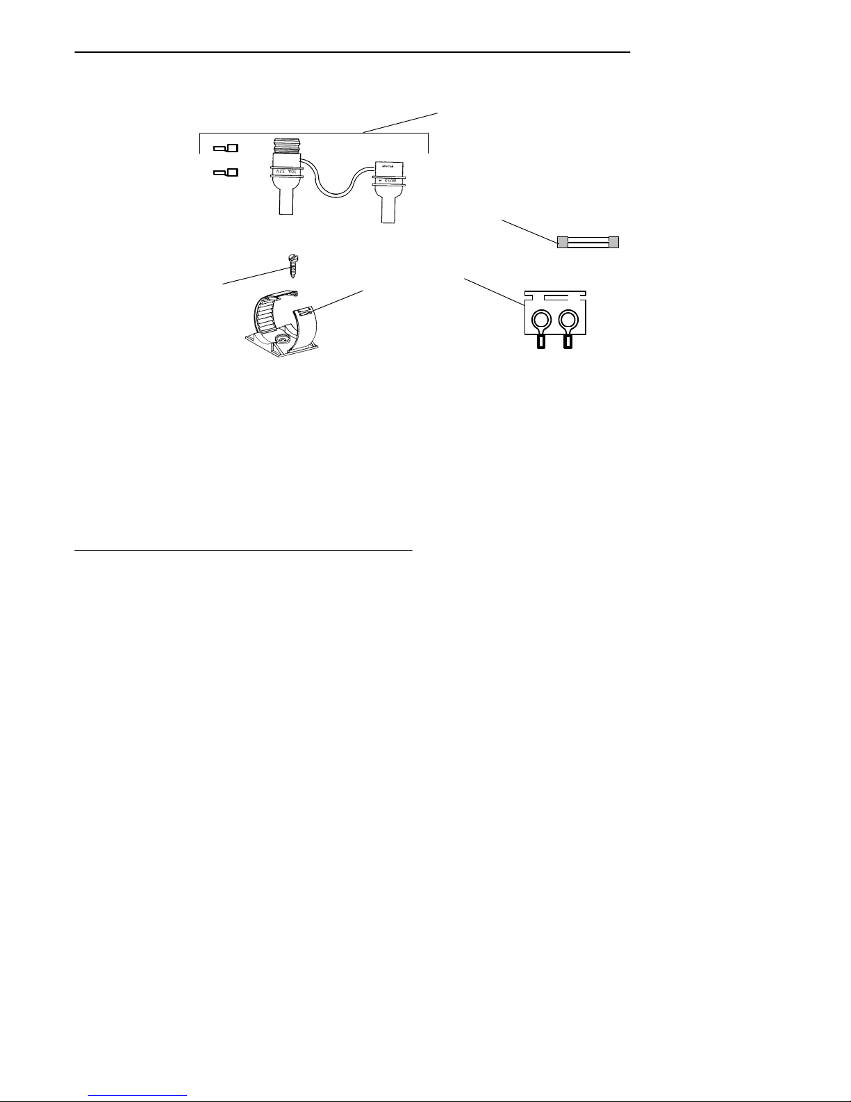
Assembling the In-line Fuse Holder
The in-line fuse holder consists of a rubber boot, two crimp-type fuse clips,
and a 15 amp fuse. Carefully follow these instructions to assemble the inline fuse holder.
1. Locate the in-line fuse holder components.
2. Cut the red wire in the gray power cable, midway between its end
3. Strip approximately 1/4-inch of insulation from the red wire that ex-
4. Slide the longer portion of the in-line fuse holder boot (yellow rub-
5. Slip a fuse clip onto this wire and crimp the clip onto the wire.
6. Slip the remaining fuse clip onto one end of the 6 inch wire saved
7. Slide this wire into the other half of the fuse holder boot. Insert the
SECTION 2 " Installation Instructions
and the gray cablejacket. Save the 6-7 inch length of red wire.
tends from the power cable; also strip 1/4-inch of insulation from
both ends of the 6 inch length of red wire saved in step #2.
ber) over the red wire that extends from the power cable.
from step #2 and crimp securely.
fuse into the fuse clips and snap the halves of the fuse holder boot
together.
RT5900 SERIES Mobile Mount Radio Data Terminal 2-5
Page 22

SECTION 2 " Installation Instructions
1
6
3
5
4
1. Fuse clips
2. Red wire (6--7 inches)
3. Fuse holder ”boot”
4. Red wire
5. Gray power cable
6. Brown (or Black) wire
2
Figure 2-3
Assembling the In-Line Fuse Holder
2-6 RT5900 SERIES Mobile Mount Radio Data Terminal
Page 23

SECTION 2 " Installation Instructions
Terminating Wire Ends
Crimp 3/8-inch terminal rings to the stripped end of the brown wire and to
the red wire from the fuse holder. See the battery drawing and instructions
for recommended assembly to connect the cable to the vehicle battery.
1. Strip approximately 1/4” of insulation from the brown (or black) wire
from the power cable.
2. Crimp the 3/8” terminal ring onto this wire.
3. Fasten the brown (or black) wire to the negative battery terminal.
4. Crimp a 3/8” terminal ring onto the red wire from the end of the inline fuse holder
5. Fasten this wire to the positive battery terminal.
--
Insert fuse into clips.
Snap fuse holder
together.
RT5900 SERIES Mobile Mount Radio Data Terminal 2-7
+
Figure 2-4
Terminating Wire Ends
Page 24

SECTION 2 " Installation Instructions
2
1
4
7
5
6
1. Bolt
2. Nut
3. Vehiclebattery
4. Vehiclebattery cable
5. In-line fuse holder
6. Terminalring
7. Washers
3
Figure 2-5
Side Mount Battery
Side Mount Battery Connection
1. Remove both battery cable retaining screws from the vehicle battery.
2. Screw a 3/8” nut as far as it will go onto a 3/8” x 1-1/2” bolt.
3. Slip a 3/8” flat washer onto the bolt.
4. Slide the positive (red wire) terminal ring of the 7524Norand power
cable onto the bolt.
5. Slip a second 3/8” flat washer onto the bolt.
6. Slide the vehicle positive battery cable onto the bolt.
7. Thread the bolt assembly into the positive battery terminal; tighten
securely.
8. Tightenthe nut installed in step #2 against the washers and battery
terminals.
Repeat steps #2 thru #8 for the negative wire (black or brown) from the
power cable, hooking up the wires to the negative battery terminal.
2-8 RT5900 SERIES Mobile Mount Radio Data Terminal
Page 25

Power Cable Connection
SECTION 2 " Installation Instructions
1
6
5
1. 3/8” nut
2. Vehiclebattery
3. Vehiclebattery cable
4. Fuse link
5. 3/8” X 1-1/2” bolt
6. 3/8” washers
4
2
3
Figure 2-6
Top Mount Battery
Top Mount Battery Connection
Connect the positive (red wire) terminal ring from the power cable to the
positive battery terminal, as shown, using a 3/8” x 1-1/2” bolt, a flat washer
on each side of the terminal ring, and two 3/8” nuts. Connect the negative
(black or brown wire) terminal ring from the power cable to the negative
battery terminal, using a 3/8” x 1-1/2” bolt, a flat washer on each side of the
terminal ring, and two 3/8” nuts.
Secure the Power Cable
Secure the power cable every 18 inches with adjustable cable clamps. Work
from the battery, toward the mounting area for the mobile mount radio data
terminal. Remove the paper backing from a clamp and stick the clamp in
place while drilling a pilot hole with a #26 drill bit. Use #6 sheet metal
screws to permanently hold clamps in place.
RT5900 SERIES Mobile Mount Radio Data Terminal 2-9
Page 26

SECTION 2 " Installation Instructions
Mounting the Terminal
The mounting kit consists of a pre-drilled mounting bracket, four mounting
knobs, and four lock washers. Use at least two sets of 3/8” bolts, nuts, flat
washers and lock washers to install the mounting bracket. Since installations can vary and may require different bolt lengths, that hardware is not
furnished in this kit and must be purchased locally. Mounting bolts should
be evenly spaced.
Install the mounting bracket and tighten all hardware securely. Support the
Mobile Mount Radio Data Terminal so the standoffs line up with the desired
holes in the mounting bracket. Note that the upper holes are arranged in an
arc to adjust the viewing angle of the unit.
Place a lock washer (provided in kit) onto each mounting knob, then screw
knobs through the holes and into the standoffs. Tighten knobs securely to
hold the terminal in place.
1
1. Bracket
2. Lock washer
3. Knob
4. Standoffs
Mounting the Terminal
2-10 RT5900 SERIES Mobile Mount Radio Data Terminal
2
3
4
Figure 2-7
Page 27

SECTION 2 " Installation Instructions
1
2
4
3
1. 15-pin connector
(communication)
2. Power connector
3. On/Off switch
4. 9-pin connector
(scanner)
Figure 2-8
Cable Connections
Connections to the Terminal
Connect cables as shown in Figure 2-8. Simply align each cable connector
to the appropriate connector on the terminal and push them together. In
addition, you must turn the power cable connector clockwise to lock it in
place.
The 15-pin connector may be used for peripheral devices such as a printer
or a scale. Not all installations use this connector.
ON/OFF Button
Push this button once to turn the Mobile Mount Radio Data Terminal on.
Push the button a second time to shut the unit off.
RT5900 SERIES Mobile Mount Radio Data Terminal 2-11
Page 28

SECTION 2 " Installation Instructions
Desktop Installation Kit Instructions
Quantity Description Part #
1 Mounting bracket 699-781-001
4 Knobs 805-460-002
4 Lockwashers 803-027-000
8 Adjustable clamps 808-011-001
8 Self-tapping screws (pan head, #6
x 5/8”)
1 External power cable 216-860-001
1 AC power cord 321-054-001
1 NC4000 power supply 851-013-002
Table 2-2
Parts List
kit NPN: 203-300-006
800-008-001
Kit Description
This kit contains a power supply,power cables, and mechanical hardware to
permit desktop (nonvehicular) operation of the Mobile Mount Radio Data
Terminal.
The power cable furnished in this kit has the correct connector on one end to
fit the terminal; the other end of the cable has a push-in/screw-collar connector to fit the NC4000 Power Supply.
2-12 RT5900 SERIES Mobile Mount Radio Data Terminal
Page 29

Instructions
SECTION 2 " Installation Instructions
Mounting Bracket
Experiment with the terminal and the mounting bracket to determine the
bracket arrangement that will provide you with the best viewing angle. Use
two knobs and two lock washers on each side to attach the bracket to the
terminal. Use 3/8-inch hardware if you will be attaching the mounting
bracket to a desk, counter top, or shelving.
NC4000 Power Supply
Locate and identify the 10-foot external DC power cable (NPN:
216-860-001) in this kit along with the AC power cord. One end of the DC
power cable has a metal collar and plugs into the three-pin connector
(shown) on the NC4000 Power Supply.
Connect the DC Power Cable
1. Align the pins and push the round connector into the power supply.
2. Screw the collar into place. Do not overtighten.
3. Route the cable toward the terminal.
4. Align the cable connector to the power jack and push the connector
firmly into the jack.
5. Turnthe collar on this connector clockwise to lock it in place.
6. Use the cable clamps and screws in this kit to secure the cable, making a neat installation.
Connect the AC Power Cable
1. Plug the female end of this cable into the NC4000.
2. Plug the male end of this cable into a standard, grounded, three-prong
wall outlet.
Do not use an adapter to defeat the electrical ground.
The installation is complete.
RT5900 SERIES Mobile Mount Radio Data Terminal 2-13
Page 30

SECTION 2 " Installation Instructions
ACPOWERCONNECTO
R
DC POWER CONNECTOR
(USE CABLE #216-860--001)
(CABLE TO WALL OUTLET)
The NC4000 Power Supply
2-14 RT5900 SERIES Mobile Mount Radio Data Terminal
Figure 2-9
Page 31

Section 3
User Interface Instructions
" " " " " " " " " " " " " " " " " " " " " " " " " " " "
Introduction
The user interface for the Mobile Mount Radio Data Terminal consists of
the keyboard, the display,and the operating system (program) that allows
you to customize the unit operation.
The first section of this manual has already described the keyboard and the
display; this section of the manual tells you how to use the operating system itself.
"
NOTE: The application program (unique to your specific business or industry) is entirely
separate from the operating system and the keystrokes may have slightly different
meanings between the two types of programs.
Since the operating system is presented to you as a series of menus on the
display,the following pages are arranged in a similar fashion.
Conventions
Conventions are the rules to follow when going through the menus and
making (or not making) various choices. These rules are important to understand and remember because they apply to most of the menus within the
operating system. If a particular menu requires a unique response, this is
noted in the text that goes with that menu.
The darkened (e.g., darkened) word or phrase below represents the key(s)
you must press, followed by an explanation of what that action accomplishes.
RT5900 SERIES Mobile Mount Radio Data Terminal 3-1
Page 32

SECTION 3 " User Interface Instructions
The Keyboard
Accessing the Menu
Press the LEFT SHIFT and then the MENU (SPACE)key to access the
Main Menu.
ENTER Key
Press this key to go to the next whole (parent) menu. Multiple presses of
this key cause the program to act as a loop, taking you back, eventually,to
the starting point.
1 (or 2, 3, 4, 5, etc.)
Many menus have numbered choices. You must press the corresponding
number to make a selection. If that menu remains on the display, the choice
will be high-lighted (meaning that particular function or choice is turned
ON) and you can then make additional selections from the same menu. You
must press the ENTER key to confirm the settings and exit this type of
menu.
In some cases, when you press a number to make a selection, a different
menu (submenu) displays. These allow you to modify the choice made in
the parent menu. After the modification(s), you may (depending on the
menu and function) be permitted to return to the parent menu to make additional selections.
Other menus require a numerical input but do not necessarily have simple
choices such as 1, 2, 3, 4, etc. Instead, you may have to enter a number
from 0--32, or 1--255, or some other figure. These instances will be detailed
in the text that applies to those menus or in the menu drawings.
UP Arrow and DOWN Arrow
Use these keys to adjust the length and volume of the audible (buzzer) functions, Keyclick and Error Tone. Thearrow keys adjust other functions such
as the contrast on the display and the screen size.
Arrow keys can be made to function more efficiently, in many cases, by
pressing the FUNC or ALT key, then pressing the desired arrow key.
Entry Errors
The message “Range is” displays and the numerical value of the range is
shown. You must enter a value within that range.
3-2 RT5900 SERIES Mobile Mount Radio Data Terminal
Page 33

SECTION 3 " User Interface Instructions
Right Shift/Space
Press the RIGHT SHIFT key and then the SPACE key to change the size
of displayed text from large to small, or vice--versa.
F6
F7 F8
S
H
4
I
F
T
1. Arrow Keys
2. Right Shift
3. Left Shift
4. Alpha Shift
SHIFT key
Use this key to shift the alpha
keys between upper and lower case.
MENU
SPACE
1
2
3
MENUS
To access user menus,
press the LEFT shift key,
then the SPACE (menu) key.
RT5900 SERIES Mobile Mount Radio Data Terminal 3-3
Page 34

SECTION 3 " User Interface Instructions
Main Menu
Press the LEFT SHIFT and then the MENU (SPACE) key to call up the
main menu. The main menu appears on the display. You can then enter a
number (1 thru 7) to make a selection. Making a selection of 2, 3, 4, 5, or 7
will cause that menu to display. If you select number 1, you must enter the
password (CR52401) for that menu to become available to you.
Selection 1, Set-Up Parms, and Radio Tests (first part of selection 4, Tests),
are password-protected to guard against unwanted changes or loss of data.
If the display asks for a password, you must enter a combination of seven
(7) alpha (letters) or numeric (number) characters to access the protected
menu.
Exit Menus
When you are done making changes or adjustments to your terminal, press
number 6 (Exit Menus) to return to normal operation.
If the main menu is not displayed, press the ENTER key several times until
it does, then press number 6 when the main menu displays to return to normal operation.
MAIN MENU
1)
Set--up Parms
2)
LCD Parms
3)
Beeper Setup
4)
Tests
5)
Version Info
6)
Exit Menus
7)
More
3-4 RT5900 SERIES Mobile Mount Radio Data Terminal
Page 35

SECTION 3 " User Interface Instructions
Main Menu
1)
Set--up Parms
2)
LCD Parms
3)
Beeper Setup
4)
Tests
5)
Version Info
6)
Exit Menus
7)
More
1
Enter Password
Set--up Parms
1)
Radio #
2)
Barcode Parms
3)
Protocol Opts
4)
Display Opts
5)
Radio Comm
6)
Cold Start
LCD Parms
1)
LCD Contrast
2)
Screen Size
3)
Screen Mode
4)
Annunciators
5)
Backlight
6)
Key Uppercase
2
Beeper Setup
1)
Keyclick
2)
Error Tone
Main Menu 2
(choice #7, ”More”)
Main Menu 2
1)
Keyboard Opts
2)
Save Parms
3)
Cloning Opts
4)
Session Menu
3
Tests
1)
Peripherals
2)
Converters
3)
Memory View
4)
Packet Driver
5)
Numbers
4
Version Info
FWP59XXX
Version number
Date dd mnth yy
5 7
See below
Keyboard Opts
1) Type--Ahead
Enter Password
Save Parms
Working . . .
Please Wait
Cloning Opts
1)
Clone Prgms
2)
Clone Parms
3)
Receive Parms
RT5900 SERIES Mobile Mount Radio Data Terminal 3-5
Page 36

SECTION 3 " User Interface Instructions
Main Menu
Set Parameters
This menu is password protected to prevent unauthorized changes to the
way the terminal operates, or to prevent loss of data. You can change the
following parameters for the current (foreground) session only:
" the number that designates this radio
" barcode parameters
" protocol options
" display options
See Session Menu to determine or change the current session.
Radio #
This submenu (selection #1 in the Set-Up Parms menu) displays the current
terminal identification number. Changing the number restarts the terminal,
which then reports the new number to the host computer.
All previously made terminal setup choices remain intact when a restart is
forced as a result of changing the terminal identification number.
Advanced Setup options under the Radio # menu are used to define parameters for communicating to multiple host systems or to systems that support
multiple data streams.
Barcode Parms (goes directly to Scanner Type menu)
This selection (choice #2 in the Set Parameters menu) allows you to designate if the terminal is connected to a scanner, and if so, to specify the type
of scanner. You are then guided through additional menus to customize the
way your terminal responds to various bar code types.
3-6 RT5900 SERIES Mobile Mount Radio Data Terminal
Page 37

SECTION 3 " User Interface Instructions
Set Up Parms
1)
Radio #
2)
Barcode Parms
3)
Protocol Opts
4)
Display Opts
5)
Radio Comm
6)
Cold Start
Radio #
Enter Unit
Number:
xxx
Press A for
Advanced Setup
Scanner Type
1)
No Scanner
2)
Wand
3)
Laser
4)
Wand Emulate
Protocol Opts
1)
Host View Size
2)
Data Stream
3)
Extended Cmds
4)
5250
5)
3270
6)
VT220
7)
Native
"
NOTE: Parameter settings you make only apply to the current session. If more than one
1
6
2
5
3
4
Cold Start
Enter ”Y”
to Cold Start
Terminal:
NOT
user
accessible
Display Opts
1)
2)
Cursor Mode
3)
Remote Disp
session is available to you, use the Session Menu (#4 in Main Menu 2) to verify or
change the current session before making parameter settings.
RT5900 SERIES Mobile Mount Radio Data Terminal 3-7
Page 38

SECTION 3 " User Interface Instructions
Advanced Setup (Radio #)
This sub menu can be used to define parameters for communicating in a
multiple host environment. In the “Advanced Setup” menu (SST and OWL
only), you designate the session to be modified in the following menus.
Note that all of the menu functions shown may not actually be available to
you: this depends upon whether or not multiple hosts exist, and whether or
not different data streams are supported.
The LAN ID range is 0--254 with the RM60/70 radios, and is 0--15 with
RM80/90 radios. The Radio Configuration option allows you to configure
RM60/70-equipped terminals for specific modes and frequencies.
Host A
The designator (“Host A”) will display “B or ”C”, etc., depending upon the
selection made in the previous menu.
With the first of these menus, you can designate the data stream for this ses-
sion only. You must specify the data stream for each different session.
The second of these menus allows you to specify the radio (“unit”) number
to be used for this session only. This number is specific to this host and session type. If you create a second or third session, a different radio number
can be entered for each session.
The third menu displays the data stream previously selected for this particular session and the radio number designation. This menu allows you to designate the target host for this particular session.
3-8 RT5900 SERIES Mobile Mount Radio Data Terminal
Page 39

SECTION 3 " User Interface Instructions
"
NOTE: Selections in these menus apply only to the current session. Use the Session Menu
to verify or change the current session.
Enter Unit
Number: xxx
Host A
Enter Unit
Number: xx
Press A for
Advanced Setup
1) Host A
2) Host B
3) Host C
1) Native
2) 3270
3) 5250
4) VT220
Radio #
Advanced Setup
LAN
X
Advanced Setup
Radio Config#
XXX
Advanced Setup
Host A
ENTER
This number is
specific to the host
and session type
for this designated
session.
(A)
ENTER
ENTER
‘ADVANCED SETUP’ AP-
PLIES TO SST & OWL
ONLY
Enter a number, 0 thru 7
RM60/70 Radio TerminalConfiguration
Value Resulting Settings
0 Mode1, 225Kbps
1 Mode1, 225 Kbps
2 Mode2, Channel 10, 90 Kbps
3 Mode2, Channel 15, 90 Kbps
4 Mode2, Channel 20, 90 Kbps
5 Mode2, Channel 25, 90 Kbps
6 Mode2, Channel 30, 90 Kpbs
7 Mode2, Channel 35, 90 Kbps
8 Mode2, Channel 40, 90 Kbps
9 Mode3, 450 Kbps
Enter the name of the target host.
Host A
ENTER
(host emulation)
Unit XXX
Enter Host Name:
xxxx
RT5900 SERIES Mobile Mount Radio Data Terminal 3-9
Page 40

SECTION 3 " User Interface Instructions
Barcode Parms (continued)
The Barcode Parms flowchart shows four screens (e.g., Scanner Type, Scan
Options, Scan Options [1], Scan Options [2], plus their option menus). You
must press the ENTER key to pass from Scanner Type to Scan options, and
again to pass from one scan options menu to the next. After you have made
all choices and options, press the ENTER key while in the Scan Options
menu to return to the Set Parameters parent menu.
Scanner Type
Lets you designate the type of scanner that is connected to the terminal.
With selection 1, “No Scanner,” you can verify or pre-set the various scanner and barcode options, with the intent of connecting a scanner at a later
time. At that time, you must designate the scanner type so that the terminal
recognizes and responds to the scanner. Enter a number, 1 thru 5, then press
the ENTER key to go to the next menu.
Scan Options
Allows bar code industry standard options (Redundancy,Mod 10 Chk, Concatenate, etc.) to be enabled or disabled, and designates how the terminal
handles scanner-derived data (BC Type Char, Auto TabScan, and Auto Enter Scan). Settings for the data handling options will be specified by the
host programmer.
Within this menu, Scan Timeout (choice #7), allows you to specify the scanner timeout period. You can select from 1--200 seconds. For instance,
shorten the timeout period when using a proximity scanner to reduce error
scans; when using a long-range scanner it may be helpful to extend the
timeout period to allow for more accurate scanner aiming.
3-10 RT5900 SERIES Mobile Mount Radio Data Terminal
Page 41

Barcode Parms
1
Scanner Type
No Scanner
1)
Wand
2)
Laser
3)
Wand Emulate
4)
Auto Detect
5)
2
Scan Options
1)
Redundancy
2)
MOD 10 Chk
3)
Concatenate
4)
BC TypeChar
5)
Stream Scan
6)
Scan All Flds
7)
Scan Timeout
3
Scan Options
1)
UPC
2)
EAN
3)
Code 39
4)
Code 128
5)
Codabar
4
Scan Options
1)
Plessey
2)
STR 2of5
3)
INT 2of5
4)
CI 2of5
5)
Code 11
6)
Code 93
SECTION 3 " User Interface Instructions
Specify scanner timeout period. Range is
1--200 seconds.
Scan Timeout
Seconds
XXX
See Scan Options (1)
See Length options
See Scan Options (2)
See Length options
Set-up Parms menu
RT5900 SERIES Mobile Mount Radio Data Terminal 3-11
Page 42

SECTION 3 " User Interface Instructions
Scan Options [1]
Designates the bar codes to be recognized by the terminal. When you select
a bar code type, an option menu (see Scan Options [1] ) displays to further
define your choice. If you will not be selecting a bar code type within the
Scan Options [1] menu, press the ENTER key to go directly to the Scan
Options [2] menu.
When all of the options for a particular bar code have been selected, you
must press the ENTER key. The next menu allows you to set the minimum
and maximum lengths (of the selected bar code) that will be recognized by
the terminal. After designating those lengths, press the ENTER key to return to the Scan Options [1] menu, where you can make another selection.
When all desired bar codes, their options, and their lengths have been set in
the scanner options menus, press the ENTER key to move to the Scan Options [2] menu.
Scan Options [2]
Designates additional bar codes to be recognized by the terminal. When a
bar code type is selected, an options menu displays to further define your
choice. If you will not be selecting a bar code type within the Scan Options
[2] menu, press the ENTER key to return to the Set Parameters menu.
When you have selected all of the options for a particular bar code, you
must press the ENTER key. The next menu allows you to set the minimum
and maximum lengths of the selected bar code that will be recognized.
Press the ENTER key to return to the Scan Options [2] menu, where you
can make a second (or third, fourth, etc.) selection. When all desired bar
codes, their options, and their lengths have been set in this menu, press the
ENTER key to return to the Set Parameters menu.
You can now make another selection from the Set Parameters menu (press a
number, 1 thru 7), or press the ENTER key to return to the Main Menu.
3-12 RT5900 SERIES Mobile Mount Radio Data Terminal
Page 43

SECTION 3 " User Interface Instructions
UPC
1)
Enabled
2)
Add--on 2
3)
Add--on 5
4
Sys 1 UPCE
5)
Sys 2 UPCE
6)
Expand E to A
EAN
1)
Enabled
2)
Add--on 2
3)
Add--on 5
4)
Expand 8to13
Code 39
1)
Enabled
2)
Chk Digit
3)
Extended
4)
Encoded
5)
Auto--Encoded
6)
Relax Std
7)
Full ASCII
Plessey
1)
Enabled
2)
Mod 10 Chk
3)
Mod 1 Chk
Relax Code 39
1)
Quiet Zone
2)
Data Decode
3)
Element Decode
4)
START Decode
Code 128
1)2)Enabled
UCC/EAN
Codabar
1)2)Codabar
ABC codabar
Scan
Options
[1]
Scan
Options
[2]
Str 2of5
1)2)Enabled
Disabled
Code 11
1)
Int 2of5
1)2)Enabled
Chk Digit
CI 2of5
1)
Enabled
2)
Disabled
Enabled
2)
Chk Digit1
3)
Chk Digit 2
Code 93
1)
Enabled
2)
Disabled
RT5900 SERIES Mobile Mount Radio Data Terminal 3-13
Page 44

SECTION 3 " User Interface Instructions
Other Scan Options [1] & [2]
After making your selection from the scan options menus, an options menu
for the chosen bar code type displays. Press the corresponding number(s) to
highlight your choice(s) and make the selection(s).
Then, press the ENTER key to display the Lengths menu, where you can
select minimum and maximum bar code lengths. The display returns to the
Scan Options when you press the ENTER key.
You can then make another selection within the Scan Options menu, repeating the selection processes described above for each additional menu
choice.
Lengths Options
After making your selection from the Scan Options menus, the display progresses to the XXXXXXX Opts menu (“XXXXXXX” will be the name of
the parent menu such as “UPC Opts”) where you can select bar code length
options.
The first length menu shows only one parameter (Enter Max Len: XX); the
second length menu displays the original parameter plus the current (second) one. The Length menu expands, as shown, as you press the ENTER
key.
Numerical entries, if any,must be between 1 and 99. Illogicalentries, such
as setting the minimum greater than the maximum, are not allowed.
3-14 RT5900 SERIES Mobile Mount Radio Data Terminal
Page 45

SECTION 3 " User Interface Instructions
BARCODE LENGTH MENUS
XXXXXXX
Max Length:XX
XXXXXXX
Max Length:XX
Min Length: XX
XXXXXXX
Max Length:XX
Min Length: XX
Fix Length 1: XX
XXXXXXX
Max Length:XX
Min Length: XX
Fix Length 1: XX
Fix Length 2: XX
Screens below allow you to drop
up to 15 leading or trailing characters from the bar code. Typically used to remove check digits
or non-significant zeros.
XXXXXXX
Drop Leading: XX
XXXXXXX
Drop Leading: XX
Drop Trailing: XX
XXXXXXX
Max Length:XX
Min Length: XX
Fix Length 1: XX
Fix Length 2: XX
Fix Length 3: XX
XXXXXXX
Max Length:XX
Min Length: XX
Fix Length 1: XX
Fix Length 2: XX
Fix Length 3: XX
Fix Length 4: XX
RT5900 SERIES Mobile Mount Radio Data Terminal 3-15
Page 46

SECTION 3 " User Interface Instructions
Protocol Options
Host View Size
The default value for display width is shown. This option tells the terminal
that the host computer sends information in a different size or format.
When the width line is highlighted, you can enter a number, 1 thru 80, to
change the width of the display.
Data Stream
Specifies the terminal emulation used by the host computer to communicate
to the terminal. Choices are: (1) Native, (2) 3270, (3) 5250, or (4) VT220.
Extended (5250) CMDS
These commands are used by the terminal for functions that are not normally available to the host computer. With this option enabled, the host computer can change these parameters on the terminal:
" RS-232 communications (e.g., printer)
" bar code options
" display screen and font size
VT220/3270/5250 Options
" Keyboard Lock locks the keyboard when the PA-1, PA-2, or the
CLEAR key is pressed.
" Auto Tab Scan causes the display to automatically move to the next
field after a good scan.
" Beep On Error provides warning of an error while allowing work to
progress (keyboard is normally locked when an error occurs).
" Local Echo, when enabled, reduces data transaction time and speeds
up transmissions.
3-16 RT5900 SERIES Mobile Mount Radio Data Terminal
Page 47

Host View Size
Width
80
Default shown
Enter 1--80 to
change width
Data Stream
1)
Native
2)
3270
3)
5250
4)
VT220
SECTION 3 " User Interface Instructions
Protocol Opts
1)
Host View Sze
2)
Data Stream
3)
Extended Cmds
4)
5250
5)
3270
6)
VT220
7)
Native
1
7
Native
1)
F1 is FUNCT 0
Default is enabled.
When enabled, pressing <F1> is
equivalent to pressing Gold
2
(“right shift”) 0, while pressing
<F2> is equivalent to pressing
Gold 1. When disabled, pressing <F1> is equivalent to pressing Gold 1, and <F2> is equivalent to Gold 2, etc.
Extended Cmds
1)
Enabled
2)
Disabled
5250 Opts
1)
Beep On Error
2)
Auto TabScan
6
3
5
4
CR to CRLF
2)
Auto Entr Scn
3)
Auto TabScan
4)
Local Echo
5)
3270 Options
1)
Keybrd Unlock
2)
Auto TabScan
3)
Auto Entr Scn
4)
Emulate 3210
VT220 Options
DEL to BS
1)
RT5900 SERIES Mobile Mount Radio Data Terminal 3-17
Page 48

SECTION 3 " User Interface Instructions
Display Options
Cursor Mode
Specify the cursor style (on the display) that you prefer. The display shows
an icon of the selected cursor style. Select one of the following:
1. Underline Blink
2. Block Blink
3. Underline
4. Block Cursor
1)
2)
3)
4)
2
Cursor Mode
Underln Blink
Block Blink
Underline
Block
Display Opts
1)
2)
Cursor Mode
Cold Start (not shown)
You can perform a cold start from this menu. Press the “Y” key to tell the
computer that you understand the consequences and that it should perform
the cold start. Press any other key, instead of the “Y,”to abort the cold start
and exit the menu.
Radio Comm
This allows you to specify different communication parameters. Making
one of the following selections causes the program to go to a sub-menu so
that you can further define that communication function:
" (Host) Protocol
" Baud Rate
3-18 RT5900 SERIES Mobile Mount Radio Data Terminal
Page 49

SECTION 3 " User Interface Instructions
Protocol
This allows you to choose the communication protocol that the terminal
must use to communicate to the host computer.
Choices are:
" SST
" SST Diag Mode
Baud Rate
In this submenu you will specify the communication speed (rate) at which
the terminal talks to the host computer:
Choices are:
1. 4800
2. 4800/9600
3. 9600
Radio Comm
Protocol
1)
Not used in SST
2)
Protocol
1)
RTCSST
2)
SST Diag Mode
Not used in SST
Diagnostic mode disables
data compression. It is
used for engineering tests.
RT5900 SERIES Mobile Mount Radio Data Terminal 3-19
Page 50

SECTION 3 " User Interface Instructions
Main Menu
LCD Parms
You can adjust the liquid crystal display (LCD) by:
" changing the contrast
" changing the screen size
" relocating the cursor (Screen Mode)
Contrast
Use the Up and Down arrow keys to adjust the contrast on the display.
Select Size
Use the Up and Down arrow keys to adjust the screen size.
Screen Mode
The purpose of the screen mode selection is to keep the cursor visible on
your display. If text is hard to read or modify,select a different Screen
Mode.
“Center Cursor” (default choice) works best with programs that use the
entire 80-column screen. In this mode, the cursor tends toward the center of
the display. If the cursor travels very far beyond the center of the display,
text is repositioned.
“Corner Mode” and “Page Mode” options also work to keep the cursor on
the display. They focus on different areas of the text (corner, or entire
page), in an attempt to keep the cursor visible. Corner Mode works best for
application programs that use the upper left corner of the display.
“Page Mode” causes the screen to change to the next whole screen whenever the cursor reaches the sides or the upper or lower limits of the current
display
Key Uppercase
Letters entered in lowercase show up on the display as uppercase when this
option is selected.
3-20 RT5900 SERIES Mobile Mount Radio Data Terminal
Page 51

LCD Contrast
User cursor UP and
DOWN keys to adjust
SECTION 3 " User Interface Instructions
LCD Parms
1)
LCD Contrast
2)
Screen Size
3)
Screen Mode
4)
Annunciators
5)
Backlight
6)
Key Uppercase
7)
Scroll Window
Scroll Window
1)
7
Tab Size
2)
Screen Size
3)
Define Width
4)
Define Height
Choices 1 and 2 define amount of cursor movement. Choices 3 and 4 allow
you to customize screen size.
1
Screen Size:
40
Off
8
Off
10
On
12
Off
16
21
25
Screen Mode
1)
Center Cursor
2)
Corner Mode
3)
Page Mode
4)
Lazy Mode
0--255
60
Off
Off
Off
Off
80
Off
Off
Off
Off
Off
Off
6
2
5
3
4
Key Uppercase
When selected (highlighted), all lower case
keyboard entries are
displayed in upper
case.
BLight Intensity
User cursor UP and
DOWN keys to adjust
Low
Annunciators
User cursor UP and
DOWN keys to change
annunciator location
on the display.
”Lazy Mode” repositions
text only as needed to
keep cursor in view.
"
NOTE: In the Screen Size (#2) menu above, ON indicates 40 columns by 12 lines is
selected. Blank areas indicate “not availabe.”
RT5900 SERIES Mobile Mount Radio Data Terminal 3-21
Page 52

SECTION 3 " User Interface Instructions
Display Annunciators
Annunciators show the radio terminal’scurrent status or operation in progress. The following lists some of the annunciators common to all emulations.
+
-
Low Battery Annunciator: When the low battery annunciator
appears, you may want to connect the battery pack to a charger as soon as
possible. (This only applies to hand-held terminals.)
Y
Alpha Character Shift Mode: The terminal keyboard is in the
alpha character shift mode—any alpha character keystrokes are entered as
uppercase characters.
A
(Colored) Shift Mode: The terminal keyboard is in a colored shift
mode—keystrokes enter the symbol or perform the function shown on the
overlay just to the upper left of the key. The color of the key varies depend-
ing on the emulation and the terminal type.
"
(Colored) Shift Mode: The terminal keyboard is in a colored shift
mode—keystrokes enter the symbol or perform the function shown on the
overlay just to the upper right of the key. The color of the key varies de-
pending on the emulation and the terminal type.
X
Input Inhibited: The keyboard has accepted enough information
for the current input field. If the “key ahead” feature is on, the terminal
stores the keystrokes made after “input inhibited” appears. The host may
also inhibit (lockout) the keyboard upon certain errors or when sending
additional information to the terminal.
^
Insert Mode: Characters are inserted, not overwritten.
3-22 RT5900 SERIES Mobile Mount Radio Data Terminal
Page 53

SECTION 3 " User Interface Instructions
Again, these are just a few of the display annunciators that are common to
all emulations. There are others, specific to individual emulations, that are
not shown here.
Annunciator bibliography (emulation/reference source/Norand Part Number)
" VT220 emulation: VT220/ANSI Terminal Emulation Programmer’s
Reference Guide. (NPN 977-047-037)
" 5250 emulation: 5250 SNA and Asynchronous Terminal Emulation
Programmer’sReference Guide. (NPN 977-047-039)
" 3270 emulation: 3270 Terminal Emulation Programmer’s Reference
Guide. (NPN 977-047-040)
" NATIVE emulation: Native Async Terminal Emulation Program-
mer’s Reference Guide. (NPN 977-047-038)
RT5900 SERIES Mobile Mount Radio Data Terminal 3-23
Page 54

SECTION 3 " User Interface Instructions
Main Menu
Beeper Setup
This menu allows you to adjust the volume and the length (duration) of the
tone for the audible key click indicator or for the error tone. Volume is adjustable in steps, from 0--32, while Length is adjustable in steps from 0--10.
You can select either (1) Key Click or (2) Error Tone from this menu.
Key Click
You can adjust (1) Volumeor (2) Length by pressing the corresponding
number. Then, use the Up or Down arrow key to make the desired adjustment.
Error Tone
You can adjust (1) Volume or (2) Length by pressing the corresponding
number. Then, use the Up or Down arrow key to make adjustments.
3-24 RT5900 SERIES Mobile Mount Radio Data Terminal
Page 55

SECTION 3 " User Interface Instructions
Beeper Setup
KeyClick
1)
Error Tone
2)
KeyClick
1)
Volume
2)
Length
3)
1
Volume
User cursor UP and
DOWN keys to adjust.
Keyclick > 5
Range = 0-32
Default = 5
2
Error Tone
1)
Volume
2)
Length
3)
Length
User cursor UP and
DOWN keys to adjust.
Keyclick > 3
(or Error Tone > 3)(or Error Tone > 5)
Range = 0-10
Default = 3
RT5900 SERIES Mobile Mount Radio Data Terminal 3-25
Page 56

SECTION 3 " User Interface Instructions
Main Menu
Tests
Tests menu has five choices that you select by entering the appropriate number: (1) Peripherals, (2) Converters, (3) Memory View(4) Packet Driver, or
(5) Numbers.
Peripherals (see Peripherals menu)
You can test the following from within this menu:
" Radio
" RS-232 loop
" LCD display
" Keyboard
" Scanner
Converters
Tests the analog-to-digital ( A to D) and the digital-to-analog (D to A) converters. The RSSI (not available on all radios) Test offers a choice of
graphic displays of the received radio signals.
Memory View
Software engineers use this option to see how much memory is free and
how much is used. Press the F2 key to view the heap, or press the F3 key to
view the far heap. Press the F1 key to exit Memory View.
Packet Driver
Packet Statistics (“Stats”) displays the number of packets and errors sent
and received, and shows the number of packets that were dropped.
Numbers
The display fills with moving hex numbers to indicate that the processor is
still running. Used to detect lockups during severe operating conditions.
3-26 RT5900 SERIES Mobile Mount Radio Data Terminal
Page 57

Peripherals
1)
Radio Test
2)
RS232 Test
3)
Display Test
4)
Keyboard Test
5)
Scanner Test
Radio Test requires
a unique password.
SECTION 3 " User Interface Instructions
Tests
1)
Peripherals
2)
Converters
3)
Memory View
4)
Packet Driver
5)
Numbers
1
5
Numbers
The entire display is
filled with hex numbers
that march across and
scroll vertically. Character movement indicates the processor is
still running.
Used during environmental testing.
Converters
1)
A to D
2)
D to A
3)
RSSI Test
RSSI stands for Received
Signal Strength Indicator
Memory View
F1
-- Exit
F2
-- Heap
F3
-- Far Heap
Address: 0
2
4
3
Packet Driver
1)
Link Test
2)
Link Watch
3)
Packet Stats
4)
Histogram
5)
RT5900 SERIES Mobile Mount Radio Data Terminal 3-27
Page 58

SECTION 3 " User Interface Instructions
Peripherals Menu
Radio Tests
The Radio test is used for calibration purposes and is password-protected by
a unique seven-digit password before the menu will display. Technicians
and engineers may use these tests to determine the performance of the radio
transceiver at different communication speeds and modes of operation.
RS Loop
The RS-232 serial port test requires a special loopback connector which
loops back TX to RX, DTR to DSR, and CTS to RTS. An alternating pattern is sent on each output line and checked for validity at the input line.
The condition of each line pair is reported on the display as passing or failing the test.
LCD Display
When you select this test, you will be prompted to use the UP and DOWN
arrow keys to vary the contrast. Relative contrast is indicated by a number.
You must press the ENTER key a total of four times to exit the LCD Display test; pressing the ENTER key results in a predetermined test sequence.
The fourth press of the ENTER key causes the display to return to the Peripherals menu.
Keyboard
This test produces a mockup of the keyboard on the display. Each key is
represented by one or more lower case letter x’s;press the highlighted key
to test it. A good test results in the x’s becoming upper case. The cursor
then moves to the next key.
Scanner
Attach a scanner and scan bar codes. Codes are displayed and their length is
identified.
3-28 RT5900 SERIES Mobile Mount Radio Data Terminal
Page 59

Enter unique
7--digit password.
Radio Tests
1)
Random Send
2)
Alt Send
3)
Receive
4)
Center Freq.
Random Send
BAUD RATE:
4800
SECTION 3 " User Interface Instructions
This will be the name of whichever Radio Testis in progress.
You must enter the baud rate
(4800 or 9600) for each test.
Random Send
RADIO TEST
4800
Any key
to stop test
ON
RS--232 Test
Attach RS232
Loopback
Connector.
Press ENTER.
RS--232 Test
RTS--CTS:
DTR--DSR:
TX--RX:
Any Key to Stop
PASS
PASS
PASS
Use the F-1 key to set the ON
and OFF duty cycle of the test.
Tells if the test is ON or if it
is OFF at this time.
RT5900 SERIES Mobile Mount Radio Data Terminal 3-29
Page 60

SECTION 3 " User Interface Instructions
Main Menu
Version Info
This choice from the main menu tells you the version (expressed in an alpha-numeric code) of the firmware stored within your radio data terminal.
The date that firmware was released, and the identification number of the
terminal are also displayed.
Version Info
FWP59xxx
Version: N.nn
Date: nn/nn/nn
Table 3-1
Firmware Table
Version Data Stream
FWP59xC0 Native (only)
FWP59xL0 5250 (only)
FWP59xS0 3270 (only)
FWP59xT0 VT220
3-30 RT5900 SERIES Mobile Mount Radio Data Terminal
Page 61

Main Menu
More
SECTION 3 " User Interface Instructions
Exit Menus
This choice is provided in the Main Menu as a separate selection (#6) to
ensure against accidental departure from the operating system. You must
return to the Main Menu and select #6 to exit the operating system.
Keyboard Opts
Select (1) Type-Ahead if you want to make keystrokes faster than they can
be displayed.
Save Parms
Select (2) Save Parms, then enter the seven-digit password (CR52401) if
you want to preserve parameter settings. Make sure the parameters are set
correctly before choosing Save Parms. Settings that have been saved in this
manner are retained when you perform a Cold Start, and also remain effective even when the terminal is turned off and is later turned on.
Use this option sparingly. Each time it is used, it occupies additional
memory space because previously saved changes are not erased.
"
NOTE: The Cloning Option described below is NOT ENABLED on 5900 SERIES terminals.
Cloning Opts
This function allows you to “clone” (copy) either an application program or
parameter settings from one terminal (the “source” terminal) to another (the
“target” terminal). This requires a cloning cable and both terminals must be
correctly set up for cloning.
To clone an application program from one terminal to another:
1. Connect the terminals using the cloning cable.
2. Turnthe source terminal ON, open the Cloning Opts menu, and select #1, “Clone Prgms.”
3. Hold down any key and turn the target (receiving) terminal ON; the
program from the source terminal will be downloaded into the target
terminal.
RT5900 SERIES Mobile Mount Radio Data Terminal 3-31
Page 62

SECTION 3 " User Interface Instructions
To clone parameters from one terminal to another:
1. Make sure the desired parameters are already set and saved in the
source terminal.
2. Connect terminals together via the cloning cable.
3. Withboth terminals ON, access the Cloning Opts menu.
4. On the source terminal, select menu item #2, “Clone Parms.”
5. On the target terminal, select menu item #3, “Receive Parms.”
Main Menu 2
(choice #, “More”)
Main Menu 2
1)
Keyboard Opts
2)
Save Parms
3)
Cloning Opts
4)
Session Menu
Keyboard Opts
1) Type--Ahead
Enter Password
Save Parms
Working . . .
Please Wait
3-32 RT5900 SERIES Mobile Mount Radio Data Terminal
Cloning Opts
1)
Clone Prgms
2)
Clone Parms
3)
Receive Parms
Session Menu
1)
Switch
2)
Set Hot Key
3)
Copy Setup
(Copy Setup is password protected)
Page 63

SECTION 3 " User Interface Instructions
Session Menu
The Session Menu allows you to define different host communication sessions and to designate a “hot key” that allows switching quickly between
different sessions. When you select Set Hot Key,the current hot key is displayed. Use the cursor up and down keys to view the available choices.
When the desired key name is highlighted, press ENTER to make your
selection.
Session Menu
1)
Switch
2)
Set Hot Key
3)
Copy Setup
Enter
Password:
> . . . . . . .
Select Session
Use Cursor Up
and Down Keys
To Adjust
Session x
Host: xxxx
<Datastream> xxx
1
3
“Copy Setup” (#3)
copies parameters of the
background session to
the current session.
Use “Switch” to change the
current session. The current
(or intended) session must be
identified (or designated) before setting Parameters.
(Copy Setup is password
protected)
Set Hot Key
2
Use Cursor Up
and Down Keys
To Adjust
< xx >
“Set Hot Key” is only used
for terminals that support
session switching.
RT5900 SERIES Mobile Mount Radio Data Terminal 3-33
Page 64

SECTION 3 " User Interface Instructions
3-34 RT5900 SERIES Mobile Mount Radio Data Terminal
 Loading...