


6710 Access Point
USER’S GUIDE
" " " " " " " " " " " " " " " " " " " " " " " " " " " "
P/N 961-047-081
Revision C
July 1998

" NOTICE This publication contains information proprietary to Intermec Technologies Corpo-
ration. It is being supplied to you with the express understanding that the information contained herein is for the benefit of the contracting party only, and may
not be copied, distributed, or displayed to third parties without the express written consent of Intermec Technologies Corporation, and shall be returned to Intermec Technologies Corporation upon written request. If a purchase, license, or
nondisclosure agreement has been executed, the terms of that agreement shall
govern this document.
This publication is furnished for information only, and the information in it is
subject to change without notice. Although every effort has been made to provide
complete and accurate information, Intermec Technologies Corporation assumes
no responsibility or liability for any errors or inaccuracies that may appear in this
document.
We welcome your comments concerning this publication. Although every effort
has been made to keep it free of errors, some may occur. When reporting a specific
problem, please describe it briefly and include the book title and part number, as
well as the paragraph or figure number and the page number.
Send your comments to:
Intermec Technologies Corporation
Publications Department
550 Second Street SE
Cedar Rapids, IA 52401
INTERMEC, NORAND, PEN*KEY ,and TRAKKER are registered trademarks
and ANTARES and JANUS are trademarks of Intermec Technologies Corporation.
Ó 1996 Intermec Technologies Corporation. All rights reserved.
This publication printed on recycled paper.
Acknowledgments
Portions of this product contain software which is licensed from and is copyrighted
by Epilogue Technology Corporation, 1988--1995, all rights reserved.
DECnet and VT are registered trademarks of Digital Equipment Corporation.
Ethernet is a trademark of Xerox Corporation.
Hewlett-Packard and HP are registered trademarks and HP OpenView is a
trademark of Hewlett-Packard Company.
Microsoft is a registered trademark of Microsoft Corporation.
Netscape Navigator is a trademark of Netscape Communications Corporation.
Novell and NetWare are registered trademarks and IPX and SPX are trademarks
of Novell, Inc.
PC AT is a registered trademark of International Business Machines Corporation.
PROCOMM and PROCOMM PLUS are registered trademarks of DataStorm
Technologies, Inc.
Proxim and RangeLAN are trademarks of Proxim, Inc.

FCC Computer Compliance
" NOTICE This equipment meets Class B digital device limits per Part 15 of FCC Rules.
These limits protect against interference in a residential area. It emits, uses, and
can radiate radio frequency energy. If you do not install and use the equipment
according to its instructions, it may interfere with radio signals. However, there is
no guarantee that interference will not occur in a particular installation.
If this equipment does cause harmful interference to radio or television reception,
which can be determined by turning our equipment off and on, the user is encouraged to try to correct the interference by one or more of the following measures:
" Reorient or relocate the radio or television receiving antenna.
" Increase the separation between the computer equipment and receiver.
" Connect the equipment into an outlet on a circuit different from that to
which the radio or television receiver is connected.
" Consult the dealer or an experienced radio or television technician for
help.
FCC Spread Spectrum Radio Certification
" NOTICE This device is certified to operate under Part 15, Subpart C, Section 15.247 of the
FCC rules for Intentional Radiation Products. This certification includes Docket
87-389 covering rules effective June 1994. It may not cause interference to
authorized radio communication devices, and must accept any interference caused
by those devices.
Antenna Requirements
" NOTICE FCC rules section 15.203 and Canada’s RSS-210 require that this device be oper-
ated using an antenna furnished by Intermec Technologies Corporation. The antenna coupling on this product has been designed to accept only antennas
manufactured by us. Use of an antenna other than that furnished with the equipment is prohibited by FCC and Industry Canada rules.
Canadian Computer Compliance
This Class B digital apparatus meets all requirements of the Canadian
Interference-Causing Equipment Regulations.
Cet appareil numerique de la classe B respecte toutes les exigences du Reglement
sur le material boilleur du Canada.
Canadian Spread Spectrum Radio Certification
" NOTICE This device complies with RSS-210 of Industry Canada. Operation is subject to
the following two conditions: (1) this device may not cause interference, and (2)
this device must accept any interference, including interference that may cause
undesired operation of the device.

Canadian 2.4 GHz Radio License
" NOTICE This device requires a radio license, unless it is installed totally inside a building.
(Users must obtain this license)
Une licence radio est requise pour ces dispositifs, sauf pour ceux installés tout à
fait à l’intérieur d’un bâtiment. (Il faut que l’utilisateur obtienne cette licence.)
Telephone Installation Warning Notices
The following notices apply to equipment that may be connected to telephone lines
or systems. For your personal safety, and to protect this equipment from potential
electrical or physical damage, do NOT connect equipment to telephone lines or
data communication equipment unless the following warnings have been read,
understood, and complied with.
" Never install telephone wiring during a lightning storm.
" Never install telephone jacks in wet locations unless the jack is specifi-
cally designed for wet locations.
" Never touch uninsulated telephone wires or terminals unless the tele-
phone line has been disconnected at the network interface.
" Use caution when installing or modifying telephone lines.
" Avoid using telephone (other than cordless type) during an electrical
storm. There may be a remote risk of electric shock from lightning.
" Do not use the telephone to report a gas leak in the vicinity of the leak.
Installation du téléphone : avertissements
Les avertissements qui suivent s’appliquent à tout équipement qui peut être
branché aux lignes ou systèmes téléphoniques. Pour votre sécurité personnelle et
pour protéger l’équipement de tout dommage électrique ou physique potentiel, NE
PAS brancher un ordinateur tablette électronique ou ses périphériques aux lignes
téléphoniques ou équipements avant que les avertissements suivants aient été lus,
compris et observés :
" Ne jamais installer de câblage téléphonique pendant un orage électrique.
" Ne jamais installer de prise téléphonique dans un endroit humide à
moins que la prise ait été spécifiquement conçue pour être utilisée dans
les endroits humides.
" Ne jamais toucher les fils de téléphone ou de l’équipement terminal non
isolés à moins que la ligne téléphonique n’ait été débranchée de l’interface réseau.
" User de prudence lors de l’installation ou de la modification de lignes
téléphoniques.
" Éviter d’utiliser un téléphone (autre qu’un appareil téléphonique sans
fil) pendant un orage électrique. Il pourrait y avoir un faible risque d’électrocution par la foudre.
" Ne pas utiliser le téléphone afin de signaler une fuite de gaz à proximité
de la fuite.

B
CAUTION: Intermec Technologies Corporation suggests you buy cables from us
to connect with other devices. Our cables are safe, meet FCC rules,
and suit our products. Other cables may not be tested. They may
cause problems from electrostatic discharge or induced energy. Our
warranties do not cover loss, injury, or damage from other cables.


CONTENTS
" " " " " " " " " " " " " " " " " " " " " " " " " " " "
SECTION 1
Preface 1-1. . . . . . . . . . . . . . . . . . . . . . . . . . . . . . . . . . . . . . . . . . . . .
Purpose of This Guide 1-1. . . . . . . . . . . . . . . . . . . . . . . . . . . . . . . .
Organization 1-1. . . . . . . . . . . . . . . . . . . . . . . . . . . . . . . . . . . . . . . .
Intended Audience 1-3. . . . . . . . . . . . . . . . . . . . . . . . . . . . . . . . . . .
Related Publications 1-3. . . . . . . . . . . . . . . . . . . . . . . . . . . . . . . . .
Wireless Station User’s Guides 1-3. . . . . . . . . . . . . . . . . . . .
System Management Publications 1-4. . . . . . . . . . . . . . . . .
Customer Support 1-4. . . . . . . . . . . . . . . . . . . . . . . . . . . . . . . . . . .
SECTION 2
Features and Functional Overview 2-1. . . . . . . . . . . . . . . . . . . .
Description 2-1. . . . . . . . . . . . . . . . . . . . . . . . . . . . . . . . . . . . . . . . .
Bridging Functionality 2-2. . . . . . . . . . . . . . . . . . . . . . . . . . . . . . .
General Concepts 2-2. . . . . . . . . . . . . . . . . . . . . . . . . . . . . . . .
Access Point Bridging Layer 2-4. . . . . . . . . . . . . . . . . . . . . .
Network Organization 2-4. . . . . . . . . . . . . . . . . . . . . . . .
Forwarding 2-5. . . . . . . . . . . . . . . . . . . . . . . . . . . . . . . . . .
Pending Messages 2-5. . . . . . . . . . . . . . . . . . . . . . . . . . . .
Flooding Configurations 2-6. . . . . . . . . . . . . . . . . . . . . . .
Proxy ARP Server 2-7.. . . . . . . . . . . . . . . . . . . . . . . . . . .
Bridge Ports 2-7. . . . . . . . . . . . . . . . . . . . . . . . . . . . . . . . . . . . .
Ethernet Port 2-7.. . . . . . . . . . . . . . . . . . . . . . . . . . . . . . .
Ethernet Port Filters 2-8. . . . . . . . . . . . . . . . . . . . . . . . .
Radio Ports 2-9. . . . . . . . . . . . . . . . . . . . . . . . . . . . . . . . . .
OWL/IP Port 2-10. . . . . . . . . . . . . . . . . . . . . . . . . . . . . . . . .
6710 Access Point User’s Guide i

CONTENTS "
Configuration and Management 2-11.. . . . . . . . . . . . . . . . . . . . .
Configuration 2-11. . . . . . . . . . . . . . . . . . . . . . . . . . . . . . . . . . . .
Diagnostics and Configuration Port 2-11. . . . . . . . . . . .
Remote Access 2-12. . . . . . . . . . . . . . . . . . . . . . . . . . . . . . .
TCP/IP 2-12. . . . . . . . . . . . . . . . . . . . . . . . . . . . . . . . . . .
DHCP Client 2-12. . . . . . . . . . . . . . . . . . . . . . . . . . . . .
Telnet 2-12. . . . . . . . . . . . . . . . . . . . . . . . . . . . . . . . . . . .
HTTP 2-13.. . . . . . . . . . . . . . . . . . . . . . . . . . . . . . . . . . .
Electronic Software Distribution 2-13. . . . . . . . . . . . . . .
TFTP Client and Server 2-13. . . . . . . . . . . . . . . . . . .
Scripting 2-13.. . . . . . . . . . . . . . . . . . . . . . . . . . . . . . . .
Network Management 2-14. . . . . . . . . . . . . . . . . . . . . . . . . . . .
Sample Configuration 2-14. . . . . . . . . . . . . . . . . . . . . . . . . . . . . . . .
Components 2-16. . . . . . . . . . . . . . . . . . . . . . . . . . . . . . . . . . . . . . . . .
Accessories 2-19. . . . . . . . . . . . . . . . . . . . . . . . . . . . . . . . . . . . . . . . . .
Power Cord 2-19. . . . . . . . . . . . . . . . . . . . . . . . . . . . . . . . . . . . . .
Industrial Locking Mounting Bracket 2-19. . . . . . . . . . . . . .
SECTION 3
Installation 3-1. . . . . . . . . . . . . . . . . . . . . . . . . . . . . . . . . . . . . . . . . .
Checking the Default Configuration 3-1. . . . . . . . . . . . . . . . . . .
Preparing for the Installation 3-2. . . . . . . . . . . . . . . . . . . . . . . . .
Collecting the Equipment 3-2. . . . . . . . . . . . . . . . . . . . . . . . . . . .
Ethernet LAN Components 3-2. . . . . . . . . . . . . . . . . . . . . . .
10BASE2 Components 3-3.. . . . . . . . . . . . . . . . . . . . . . .
10BASE-T Component 3-3.. . . . . . . . . . . . . . . . . . . . . . .
10BASE5 Components 3-4.. . . . . . . . . . . . . . . . . . . . . . .
Communication Equipment 3-5. . . . . . . . . . . . . . . . . . . . . . .
Local DIAG Port Access 3-5. . . . . . . . . . . . . . . . . . . . . . .
Telnet 3-6. . . . . . . . . . . . . . . . . . . . . . . . . . . . . . . . . . . . . . .
Web Browser 3-6. . . . . . . . . . . . . . . . . . . . . . . . . . . . . . . . .
Network Management Platform 3-6. . . . . . . . . . . . . . . . . . .
Finding the Best Location 3-7. . . . . . . . . . . . . . . . . . . . . . . . . . . .
Site Survey 3-7. . . . . . . . . . . . . . . . . . . . . . . . . . . . . . . . . . . . . .
General Installation Guidelines 3-7. . . . . . . . . . . . . . . . . . .
Mounting the Access Point 3-8. . . . . . . . . . . . . . . . . . . . . . . . . . .
Horizontal (Tabletop) Mount 3-8.. . . . . . . . . . . . . . . . . . . . .
Vertical and Ceiling Mounts 3-9. . . . . . . . . . . . . . . . . . . . . . .
ii 6710 Access Point User’s Guide

CONTENTS "
Connecting to Ethernet 3-10. . . . . . . . . . . . . . . . . . . . . . . . . . . . . .
10BASE2 Ethernet 3-11.. . . . . . . . . . . . . . . . . . . . . . . . . . . . . .
End of Segment 3-11.. . . . . . . . . . . . . . . . . . . . . . . . . . . . .
Middle of Segment 3-12. . . . . . . . . . . . . . . . . . . . . . . . . . . .
10BASE5 Ethernet 3-13.. . . . . . . . . . . . . . . . . . . . . . . . . . . . . .
N-Series Transceiver 3-13. . . . . . . . . . . . . . . . . . . . . . . . . .
Vampire Tap 3-13. . . . . . . . . . . . . . . . . . . . . . . . . . . . . . . . .
10BASE-T Ethernet 3-16. . . . . . . . . . . . . . . . . . . . . . . . . . . . . .
Installing PC Cards 3-17.. . . . . . . . . . . . . . . . . . . . . . . . . . . . . . . . .
WLIF 3-17. . . . . . . . . . . . . . . . . . . . . . . . . . . . . . . . . . . . . . . . . . .
900 MHz 3-18. . . . . . . . . . . . . . . . . . . . . . . . . . . . . . . . . . . . . . . .
S-UHF 3-19. . . . . . . . . . . . . . . . . . . . . . . . . . . . . . . . . . . . . . . . . .
Applying Power 3-20. . . . . . . . . . . . . . . . . . . . . . . . . . . . . . . . . . . . .
SECTION 4
Configuration 4-1. . . . . . . . . . . . . . . . . . . . . . . . . . . . . . . . . . . . . . .
Creating a Local DIAG Port Session 4-2. . . . . . . . . . . . . . . . . . .
Accessing the Configuration Menus 4-4. . . . . . . . . . . . . . . .
Accessing the ROM Command Monitor 4-5. . . . . . . . . . . . .
Creating a Telnet Session 4-6. . . . . . . . . . . . . . . . . . . . . . . . . . . . .
Default and Site Settings 4-7. . . . . . . . . . . . . . . . . . . . . . . . . . . . .
TCP/IP 4-7. . . . . . . . . . . . . . . . . . . . . . . . . . . . . . . . . . . . . . . . . .
Security 4-8. . . . . . . . . . . . . . . . . . . . . . . . . . . . . . . . . . . . . . . . .
Bridge 4-8. . . . . . . . . . . . . . . . . . . . . . . . . . . . . . . . . . . . . . . . . .
Configuring the Access Point 4-12.. . . . . . . . . . . . . . . . . . . . . . . .
Main Menu 4-12. . . . . . . . . . . . . . . . . . . . . . . . . . . . . . . . . . . . . .
Using the View Command 4-14. . . . . . . . . . . . . . . . . . . . . . . .
TCP/IP Options 4-16. . . . . . . . . . . . . . . . . . . . . . . . . . . . . . . . . . . . . .
IP Address 4-16. . . . . . . . . . . . . . . . . . . . . . . . . . . . . . . . . . . . . .
IP Subnet Mask 4-17. . . . . . . . . . . . . . . . . . . . . . . . . . . . . . . . . .
IP Router 4-18. . . . . . . . . . . . . . . . . . . . . . . . . . . . . . . . . . . . . . . .
IP Frame Type 4-19. . . . . . . . . . . . . . . . . . . . . . . . . . . . . . . . . . .
DHCP 4-19. . . . . . . . . . . . . . . . . . . . . . . . . . . . . . . . . . . . . . . . . . .
DHCP Server Name 4-20. . . . . . . . . . . . . . . . . . . . . . . . . . . . . .
Bootp Operation 4-21. . . . . . . . . . . . . . . . . . . . . . . . . . . . . .
Networks With DHCP and Bootp Servers 4-21. . . . . . .
Handshaking 4-21. . . . . . . . . . . . . . . . . . . . . . . . . . . . . . . .
Infinite Leases 4-21. . . . . . . . . . . . . . . . . . . . . . . . . . . . . . .
Auto ARP Minutes 4-22. . . . . . . . . . . . . . . . . . . . . . . . . . . . . . .
6710 Access Point User’s Guide iii

CONTENTS "
Bridge Options 4-23. . . . . . . . . . . . . . . . . . . . . . . . . . . . . . . . . . . . . .
Serial Number 4-23. . . . . . . . . . . . . . . . . . . . . . . . . . . . . . . . . . .
Lan ID 4-23. . . . . . . . . . . . . . . . . . . . . . . . . . . . . . . . . . . . . . . . . .
[Root] 4-24.. . . . . . . . . . . . . . . . . . . . . . . . . . . . . . . . . . . . . . . . . .
Root Priority 4-24.. . . . . . . . . . . . . . . . . . . . . . . . . . . . . . . .
Super Root Candidates 4-24.. . . . . . . . . . . . . . . . . . .
Super Root Selection 4-25. . . . . . . . . . . . . . . . . . . . . .
Super Root Redundancy 4-25. . . . . . . . . . . . . . . . . . .
[Global Radio] 4-25. . . . . . . . . . . . . . . . . . . . . . . . . . . . . . . .
Set Globally 4-27. . . . . . . . . . . . . . . . . . . . . . . . . . . . . .
Value 4-27. . . . . . . . . . . . . . . . . . . . . . . . . . . . . . . . . . . .
[Global Flooding] 4-28. . . . . . . . . . . . . . . . . . . . . . . . . . . . .
Inbound 4-28. . . . . . . . . . . . . . . . . . . . . . . . . . . . . . . . . .
Outbound to Secondaries 4-29. . . . . . . . . . . . . . . . . .
Outbound to Stations 4-30. . . . . . . . . . . . . . . . . . . . . .
Flooding Level Checklist 4-31.. . . . . . . . . . . . . . . . . . . . .
S-UHF Flooding Level 4-36. . . . . . . . . . . . . . . . . . . . . . . .
Flood Register 4-36. . . . . . . . . . . . . . . . . . . . . . . . . . . . . . . .
ARP Server Mode 4-36. . . . . . . . . . . . . . . . . . . . . . . . . . . . . . . .
[Ports] 4-38. . . . . . . . . . . . . . . . . . . . . . . . . . . . . . . . . . . . . . . . . .
Name 4-39.. . . . . . . . . . . . . . . . . . . . . . . . . . . . . . . . . . . . . . .
MAC Address 4-39. . . . . . . . . . . . . . . . . . . . . . . . . . . . . . . .
Status 4-40. . . . . . . . . . . . . . . . . . . . . . . . . . . . . . . . . . . . . . .
Hello Period 4-40.. . . . . . . . . . . . . . . . . . . . . . . . . . . . . . . . .
Ethernet Options 4-41.. . . . . . . . . . . . . . . . . . . . . . . . . . . . . . . . . . .
OWL Frame Type 4-41. . . . . . . . . . . . . . . . . . . . . . . . . . . . . . . .
Cable Type 4-42. . . . . . . . . . . . . . . . . . . . . . . . . . . . . . . . . . . . . .
[Static Addresses] 4-42.. . . . . . . . . . . . . . . . . . . . . . . . . . . . . . .
[Normal RX Filter] 4-43. . . . . . . . . . . . . . . . . . . . . . . . . . . . . . .
[Frame Types] 4-44. . . . . . . . . . . . . . . . . . . . . . . . . . . . . . . .
[SubTypes 1] 4-46. . . . . . . . . . . . . . . . . . . . . . . . . . . . . . . . .
User-Defined Subtypes in [SubTypes 1]
and [SubTypes 2] 4-46.. . . . . . . . . . . . . . . . . . . . . . . .
Filtering Examples 4-48. . . . . . . . . . . . . . . . . . . . . . . . . . .
Example 1 4-49. . . . . . . . . . . . . . . . . . . . . . . . . . . . . . . .
Example 2 4-50. . . . . . . . . . . . . . . . . . . . . . . . . . . . . . . .
iv 6710 Access Point User’s Guide

CONTENTS "
[Advanced RX Filter] 4-52. . . . . . . . . . . . . . . . . . . . . . . . . . . . .
[Expressions] 4-52. . . . . . . . . . . . . . . . . . . . . . . . . . . . . . . . .
ExprSeq 4-53. . . . . . . . . . . . . . . . . . . . . . . . . . . . . . . . . .
Offset 4-54. . . . . . . . . . . . . . . . . . . . . . . . . . . . . . . . . . . .
Mask 4-54. . . . . . . . . . . . . . . . . . . . . . . . . . . . . . . . . . . .
Op 4-54. . . . . . . . . . . . . . . . . . . . . . . . . . . . . . . . . . . . . . .
Value Id 4-55. . . . . . . . . . . . . . . . . . . . . . . . . . . . . . . . . .
Action 4-55. . . . . . . . . . . . . . . . . . . . . . . . . . . . . . . . . . .
[Values] 4-56. . . . . . . . . . . . . . . . . . . . . . . . . . . . . . . . . . . . . .
[Bridging] 4-57. . . . . . . . . . . . . . . . . . . . . . . . . . . . . . . . . . . . . . .
Bridge Priority 4-57. . . . . . . . . . . . . . . . . . . . . . . . . . . . . . .
Designated Bridge Candidates 4-57. . . . . . . . . . . . .
Designated Bridge Selection 4-58. . . . . . . . . . . . . . .
Summary 4-58. . . . . . . . . . . . . . . . . . . . . . . . . . . . . . . .
Status 4-58. . . . . . . . . . . . . . . . . . . . . . . . . . . . . . . . . . . . . . .
Flood Register 4-59. . . . . . . . . . . . . . . . . . . . . . . . . . . . . . . .
WLIF Options 4-60. . . . . . . . . . . . . . . . . . . . . . . . . . . . . . . . . . . . . . .
Security Id 4-60. . . . . . . . . . . . . . . . . . . . . . . . . . . . . . . . . . . . . .
Node Type 4-61. . . . . . . . . . . . . . . . . . . . . . . . . . . . . . . . . . . . . . .
[Master Parms] 4-62.. . . . . . . . . . . . . . . . . . . . . . . . . . . . . . . . .
Channel and Subchannel 4-62. . . . . . . . . . . . . . . . . . . . . .
Network With 15 or Fewer Access Points 4-63. . . .
Network With 16 or More Access Points 4-63. . . . .
Wireless Hops 4-65. . . . . . . . . . . . . . . . . . . . . . . . . . . . . . . .
[Slave Parms] 4-66. . . . . . . . . . . . . . . . . . . . . . . . . . . . . . . . . . . .
MAC Config 4-68. . . . . . . . . . . . . . . . . . . . . . . . . . . . . . . . . . . . .
[Manual MAC Parms] 4-69. . . . . . . . . . . . . . . . . . . . . . . . . . . .
Hop Period 4-70. . . . . . . . . . . . . . . . . . . . . . . . . . . . . . . . . . .
Beacon Frequency 4-70. . . . . . . . . . . . . . . . . . . . . . . . . . . .
Deferral Slot and Fairness Slot 4-70. . . . . . . . . . . . . . . .
Fragment Size 4-71. . . . . . . . . . . . . . . . . . . . . . . . . . . . . . .
Transmit Mode 4-72.. . . . . . . . . . . . . . . . . . . . . . . . . . . . . .
Norm Ack Retry 4-72. . . . . . . . . . . . . . . . . . . . . . . . . . . . . .
Frag Ack Retry 4-73. . . . . . . . . . . . . . . . . . . . . . . . . . . . . . .
Norm QFSK Retry 4-73. . . . . . . . . . . . . . . . . . . . . . . . . . . .
Frag QFSK Retry 4-73. . . . . . . . . . . . . . . . . . . . . . . . . . . . .
900 MHz Options 4-74. . . . . . . . . . . . . . . . . . . . . . . . . . . . . . . . . . . .
File Name 4-74. . . . . . . . . . . . . . . . . . . . . . . . . . . . . . . . . . . . . . .
Mode--Channel 4-74. . . . . . . . . . . . . . . . . . . . . . . . . . . . . . . . . . .
6710 Access Point User’s Guide v

CONTENTS "
S-UHF Options 4-76. . . . . . . . . . . . . . . . . . . . . . . . . . . . . . . . . . . . . .
File Name 4-76. . . . . . . . . . . . . . . . . . . . . . . . . . . . . . . . . . . . . . .
Call Sign 4-76. . . . . . . . . . . . . . . . . . . . . . . . . . . . . . . . . . . . . . . .
Frequency 4-77. . . . . . . . . . . . . . . . . . . . . . . . . . . . . . . . . . . . . . .
Master Mode 4-77. . . . . . . . . . . . . . . . . . . . . . . . . . . . . . . . . . . .
Attach Priority 4-78. . . . . . . . . . . . . . . . . . . . . . . . . . . . . . . . . . .
OWL/IP Options 4-79. . . . . . . . . . . . . . . . . . . . . . . . . . . . . . . . . . . . .
Overview 4-79. . . . . . . . . . . . . . . . . . . . . . . . . . . . . . . . . . . . . . . .
OWL/IP Menu 4-82.. . . . . . . . . . . . . . . . . . . . . . . . . . . . . . . . . .
Mode 4-82.. . . . . . . . . . . . . . . . . . . . . . . . . . . . . . . . . . . . . . .
[IP Addresses] 4-83. . . . . . . . . . . . . . . . . . . . . . . . . . . . . . . .
Type 4-83. . . . . . . . . . . . . . . . . . . . . . . . . . . . . . . . . . . . .
Address 4-84. . . . . . . . . . . . . . . . . . . . . . . . . . . . . . . . . .
[TX Filter] 4-84. . . . . . . . . . . . . . . . . . . . . . . . . . . . . . . . . . .
Security Options 4-86. . . . . . . . . . . . . . . . . . . . . . . . . . . . . . . . . . . . .
Password 4-86. . . . . . . . . . . . . . . . . . . . . . . . . . . . . . . . . . . .
Service Password 4-86.. . . . . . . . . . . . . . . . . . . . . . . . . . . .
Advanced Password 4-87. . . . . . . . . . . . . . . . . . . . . . . . . . .
Combining Radio Options 4-87. . . . . . . . . . . . . . . . . . . . . . . . . . . .
Same LAN ID 4-87. . . . . . . . . . . . . . . . . . . . . . . . . . . . . . . . . . . .
Different LAN IDs 4-88. . . . . . . . . . . . . . . . . . . . . . . . . . . . . . .
Creating a Web Browser Session 4-88. . . . . . . . . . . . . . . . . . . . . .
Configuration Guidelines 4-92. . . . . . . . . . . . . . . . . . . . . . . . . . . . .
Planning Your Installation 4-92.. . . . . . . . . . . . . . . . . . . . . . .
Using the Configuration Guide 4-92.. . . . . . . . . . . . . . . . . . .
SECTION 5
Software Download 5-1.. . . . . . . . . . . . . . . . . . . . . . . . . . . . . . . . .
File System Structure 5-1.. . . . . . . . . . . . . . . . . . . . . . . . . . . . . . .
Boot Segments 1 and 2 5-1. . . . . . . . . . . . . . . . . . . . . . . . . . .
Data Segments 3 and 4 5-1. . . . . . . . . . . . . . . . . . . . . . . . . . .
Active and Inactive Segments 5-2. . . . . . . . . . . . . . . . . . . . .
RAM Segment 5-3. . . . . . . . . . . . . . . . . . . . . . . . . . . . . . . . . . .
Segment Names 5-3. . . . . . . . . . . . . . . . . . . . . . . . . . . . . . . . . . . . .
File Names 5-4.. . . . . . . . . . . . . . . . . . . . . . . . . . . . . . . . . . . . . . . . .
Downloading Programs 5-4. . . . . . . . . . . . . . . . . . . . . . . . . . . . . .
File Menu Commands 5-4.. . . . . . . . . . . . . . . . . . . . . . . . . . . . . . .
Fb Command 5-5. . . . . . . . . . . . . . . . . . . . . . . . . . . . . . . . . . . . . . . .
Fd Command 5-6.. . . . . . . . . . . . . . . . . . . . . . . . . . . . . . . . . . . . . . .
Fdel Command 5-7. . . . . . . . . . . . . . . . . . . . . . . . . . . . . . . . . . . . . .
vi 6710 Access Point User’s Guide

CONTENTS "
Fe Command 5-8. . . . . . . . . . . . . . . . . . . . . . . . . . . . . . . . . . . . . . . .
TFTP Command 5-8.. . . . . . . . . . . . . . . . . . . . . . . . . . . . . . . . . . . .
TFTP Server 5-9. . . . . . . . . . . . . . . . . . . . . . . . . . . . . . . . . . . . .
Server Start 5-10. . . . . . . . . . . . . . . . . . . . . . . . . . . . . . . . . .
Server Stop 5-10.. . . . . . . . . . . . . . . . . . . . . . . . . . . . . . . . .
Server Log 5-10.. . . . . . . . . . . . . . . . . . . . . . . . . . . . . . . . . .
TFTP Client Commands 5-10. . . . . . . . . . . . . . . . . . . . . . . . . .
Get 5-11. . . . . . . . . . . . . . . . . . . . . . . . . . . . . . . . . . . . . . . . . .
Put 5-12. . . . . . . . . . . . . . . . . . . . . . . . . . . . . . . . . . . . . . . . . .
Script Command 5-12. . . . . . . . . . . . . . . . . . . . . . . . . . . . . . . . . . . . .
Creating Script Files 5-13. . . . . . . . . . . . . . . . . . . . . . . . . . . . .
Sample Script File 5-14.. . . . . . . . . . . . . . . . . . . . . . . . . . . . . .
Script File Command Summary 5-15. . . . . . . . . . . . . . . . . . .
TFTP Client Command Retry 5-16.. . . . . . . . . . . . . . . . . . . .
Reboot Command 5-16. . . . . . . . . . . . . . . . . . . . . . . . . . . . . . . .
SDVars Command 5-17. . . . . . . . . . . . . . . . . . . . . . . . . . . . . . . . . . .
ServerIpAddress 5-18. . . . . . . . . . . . . . . . . . . . . . . . . . . . . . . . .
ScriptFilename 5-18. . . . . . . . . . . . . . . . . . . . . . . . . . . . . . . . . .
StartTime 5-18. . . . . . . . . . . . . . . . . . . . . . . . . . . . . . . . . . . . . . .
Status 5-19. . . . . . . . . . . . . . . . . . . . . . . . . . . . . . . . . . . . . . . . . . .
CheckPoint 5-19. . . . . . . . . . . . . . . . . . . . . . . . . . . . . . . . . . . . . .
Terminate 5-20. . . . . . . . . . . . . . . . . . . . . . . . . . . . . . . . . . . . . . .
SetActivePointers 5-21. . . . . . . . . . . . . . . . . . . . . . . . . . . . . . . .
NextPowerUpTime 5-21. . . . . . . . . . . . . . . . . . . . . . . . . . . . . . .
ROM Command Monitor 5-22. . . . . . . . . . . . . . . . . . . . . . . . . . . . .
Starting the Command Monitor 5-22. . . . . . . . . . . . . . . . . . .
Viewing ROM Commands 5-23. . . . . . . . . . . . . . . . . . . . . . . . .
B 5-23. . . . . . . . . . . . . . . . . . . . . . . . . . . . . . . . . . . . . . . . . . . . . . .
FX s 5-23. . . . . . . . . . . . . . . . . . . . . . . . . . . . . . . . . . . . . . . . . . . .
FD 5-23. . . . . . . . . . . . . . . . . . . . . . . . . . . . . . . . . . . . . . . . . . . . . .
FR 5-24. . . . . . . . . . . . . . . . . . . . . . . . . . . . . . . . . . . . . . . . . . . . . .
NPWD 5-24. . . . . . . . . . . . . . . . . . . . . . . . . . . . . . . . . . . . . . . . . .
SR z 5-24. . . . . . . . . . . . . . . . . . . . . . . . . . . . . . . . . . . . . . . . . . . .
PWD 5-25. . . . . . . . . . . . . . . . . . . . . . . . . . . . . . . . . . . . . . . . . . . .
FD 5-25. . . . . . . . . . . . . . . . . . . . . . . . . . . . . . . . . . . . . . . . . .
FE <s|all> 5-25.. . . . . . . . . . . . . . . . . . . . . . . . . . . . . . . . . .
FI 5-26. . . . . . . . . . . . . . . . . . . . . . . . . . . . . . . . . . . . . . . . . . .
FS s n 5-26.. . . . . . . . . . . . . . . . . . . . . . . . . . . . . . . . . . . . . .
FB s 5-26.. . . . . . . . . . . . . . . . . . . . . . . . . . . . . . . . . . . . . . . .
FFR f 5-26. . . . . . . . . . . . . . . . . . . . . . . . . . . . . . . . . . . . . . . .
FPC f s 5-26. . . . . . . . . . . . . . . . . . . . . . . . . . . . . . . . . . . . . .
6710 Access Point User’s Guide vii

CONTENTS "
FPD 5-26. . . . . . . . . . . . . . . . . . . . . . . . . . . . . . . . . . . . . . . . .
FPE 5-27. . . . . . . . . . . . . . . . . . . . . . . . . . . . . . . . . . . . . . . . .
FPX 5-27. . . . . . . . . . . . . . . . . . . . . . . . . . . . . . . . . . . . . . . . .
PN 5-27. . . . . . . . . . . . . . . . . . . . . . . . . . . . . . . . . . . . . . . . .
PQ 5-27. . . . . . . . . . . . . . . . . . . . . . . . . . . . . . . . . . . . . . . . . .
MI String 5-28. . . . . . . . . . . . . . . . . . . . . . . . . . . . . . . . . . . .
RMI 5-28.. . . . . . . . . . . . . . . . . . . . . . . . . . . . . . . . . . . . . . . .
X 5-28. . . . . . . . . . . . . . . . . . . . . . . . . . . . . . . . . . . . . . . . . . . .
Exiting the ROM Command Monitor 5-29.. . . . . . . . . . . . . .
Software Download Example 5-29. . . . . . . . . . . . . . . . . . . . . . . . .
Upgrading Through DIAG Port 5-29. . . . . . . . . . . . . . . . . . .
Starting the TFTP Server 5-31. . . . . . . . . . . . . . . . . . . . . . . . .
Upgrading TFTP Clients 5-31. . . . . . . . . . . . . . . . . . . . . . . . . .
SECTION 6
Indicator Lights 6-1. . . . . . . . . . . . . . . . . . . . . . . . . . . . . . . . . . . . .
Overview 6-1.. . . . . . . . . . . . . . . . . . . . . . . . . . . . . . . . . . . . . . . . . .
ETHERNET Lights 6-2.. . . . . . . . . . . . . . . . . . . . . . . . . . . . . . . . .
STATUS Lights 6-2. . . . . . . . . . . . . . . . . . . . . . . . . . . . . . . . . . . . . .
STATUS 6-3.. . . . . . . . . . . . . . . . . . . . . . . . . . . . . . . . . . . . . . . .
MODE 6-4. . . . . . . . . . . . . . . . . . . . . . . . . . . . . . . . . . . . . . . . . .
NETWORK MODE Lights 6-5. . . . . . . . . . . . . . . . . . . . . . . . . . . .
PCMCIA Lights 6-6. . . . . . . . . . . . . . . . . . . . . . . . . . . . . . . . . . . . .
Power-Up Sequence 6-7. . . . . . . . . . . . . . . . . . . . . . . . . . . . . . . . . .
APPENDIX A
Access Point Specifications A-1.. . . . . . . . . . . . . . . . . . . . . . . .
Product Specifications A-1. . . . . . . . . . . . . . . . . . . . . . . . . . . . . . . .
Electrical Specifications A-1. . . . . . . . . . . . . . . . . . . . . . . . . . . . . .
Environmental Specifications A-2. . . . . . . . . . . . . . . . . . . . . . . . .
Physical Characteristics A-2. . . . . . . . . . . . . . . . . . . . . . . . . . . . . .
viii 6710 Access Point User’s Guide

CONTENTS "
APPENDIX B
WLIF Specifications and Antennas B-1. . . . . . . . . . . . . . . . . . .
RM180 B-1. . . . . . . . . . . . . . . . . . . . . . . . . . . . . . . . . . . . . . . . . . . . . .
Radio Operation B-2.. . . . . . . . . . . . . . . . . . . . . . . . . . . . . . . .
Part Numbers B-2. . . . . . . . . . . . . . . . . . . . . . . . . . . . . . . . . . .
Antenna Regulations B-3. . . . . . . . . . . . . . . . . . . . . . . . . . . . . . . . .
Whip Antenna B-3. . . . . . . . . . . . . . . . . . . . . . . . . . . . . . . . . . . . . . .
Remote Antenna Kits B-3. . . . . . . . . . . . . . . . . . . . . . . . . . . . . . . .
Medium Gain Patch B-3.. . . . . . . . . . . . . . . . . . . . . . . . . . . . .
Medium Gain Collinear Dipole B-4. . . . . . . . . . . . . . . . . . . .
High Gain Collinear Dipole B-4. . . . . . . . . . . . . . . . . . . . . . .
High Gain Yagi B-5. . . . . . . . . . . . . . . . . . . . . . . . . . . . . . . . . .
Antenna Adapter Cable B-5. . . . . . . . . . . . . . . . . . . . . . . . . . . . . .
Model 2100 Antennas and Cables B-6. . . . . . . . . . . . . . . . . . . . .
2.4 GHz Antennas B-6. . . . . . . . . . . . . . . . . . . . . . . . . . . . . . . .
2.4 GHz Antenna Cables and Connectors B-6. . . . . . . . . . .
APPENDIX C
900 MHz Specifications and Antennas C-1. . . . . . . . . . . . . . . .
RM160 C-1. . . . . . . . . . . . . . . . . . . . . . . . . . . . . . . . . . . . . . . . . . . . . .
Radio Operation C-2.. . . . . . . . . . . . . . . . . . . . . . . . . . . . . . . .
Part Numbers C-2. . . . . . . . . . . . . . . . . . . . . . . . . . . . . . . . . . .
Antenna Regulations C-2. . . . . . . . . . . . . . . . . . . . . . . . . . . . . . . . .
Whip Antenna C-2. . . . . . . . . . . . . . . . . . . . . . . . . . . . . . . . . . . . . . .
Remote Antenna Kits C-3. . . . . . . . . . . . . . . . . . . . . . . . . . . . . . . .
APPENDIX D
S-UHF Specifications and Antennas D-1. . . . . . . . . . . . . . . . . .
RM111 D-1. . . . . . . . . . . . . . . . . . . . . . . . . . . . . . . . . . . . . . . . . . . . . .
Radio Operation D-2. . . . . . . . . . . . . . . . . . . . . . . . . . . . . . . . .
Part Numbers D-2. . . . . . . . . . . . . . . . . . . . . . . . . . . . . . . . . . .
Wireless Hops D-3. . . . . . . . . . . . . . . . . . . . . . . . . . . . . . . . . . .
Antenna Connector D-3. . . . . . . . . . . . . . . . . . . . . . . . . . . . . . . . . .
Whip Antennas D-3. . . . . . . . . . . . . . . . . . . . . . . . . . . . . . . . . . . . . .
Site License D-4. . . . . . . . . . . . . . . . . . . . . . . . . . . . . . . . . . . . . . . . .
Technology D-4. . . . . . . . . . . . . . . . . . . . . . . . . . . . . . . . . . . . . . . . . .
Transaction Rates D-4.. . . . . . . . . . . . . . . . . . . . . . . . . . . . . . . . . .
6710 Access Point User’s Guide ix

CONTENTS "
Installation Guidelines D-5. . . . . . . . . . . . . . . . . . . . . . . . . . . . . . .
Predicting Coverage D-5. . . . . . . . . . . . . . . . . . . . . . . . . . . . . .
Installing a Single Access Point D-6. . . . . . . . . . . . . . . . . . .
Installing Multiple Access Points D-6. . . . . . . . . . . . . . . . . .
Extending Coverage D-6. . . . . . . . . . . . . . . . . . . . . . . . . .
Reusing the Frequency D-7.. . . . . . . . . . . . . . . . . . . . . . .
Increasing System Throughput D-8. . . . . . . . . . . . . . . .
Option 1 D-9. . . . . . . . . . . . . . . . . . . . . . . . . . . . . . . . .
Option 2 D-9. . . . . . . . . . . . . . . . . . . . . . . . . . . . . . . . .
Frequency and Separation Guidelines D-10. . . . . . . . . .
APPENDIX E
OWL/IP E-1. . . . . . . . . . . . . . . . . . . . . . . . . . . . . . . . . . . . . . . . . . . . .
Introduction E-1. . . . . . . . . . . . . . . . . . . . . . . . . . . . . . . . . . . . . . . . .
OWL/IP Restrictions E-2.. . . . . . . . . . . . . . . . . . . . . . . . . . . . . . . .
Addressing Limitations E-2. . . . . . . . . . . . . . . . . . . . . . . . . . .
Installation Limitations E-2. . . . . . . . . . . . . . . . . . . . . . . . . . .
OWL/IP Safeguards E-3. . . . . . . . . . . . . . . . . . . . . . . . . . . . . . . . . .
Default Settings E-3. . . . . . . . . . . . . . . . . . . . . . . . . . . . . . . . .
Addressing Limitations and Flooding Restrictions E-4. . .
Permanent Filters E-4. . . . . . . . . . . . . . . . . . . . . . . . . . . . . . . .
Default Filter Settings E-6. . . . . . . . . . . . . . . . . . . . . . . . . . . .
Subnet Filtering E-6. . . . . . . . . . . . . . . . . . . . . . . . . . . . . . . . .
Password Security E-7.. . . . . . . . . . . . . . . . . . . . . . . . . . . . . .
Operation E-7.. . . . . . . . . . . . . . . . . . . . . . . . . . . . . . . . . . . . . .
Tunnel Origination E-9. . . . . . . . . . . . . . . . . . . . . . . . . . . . . . .
Building the Spanning Tree E-9. . . . . . . . . . . . . . . . . . .
Establishing and Maintaining Tunnels E-10. . . . . . . . .
Redundancy E-10. . . . . . . . . . . . . . . . . . . . . . . . . . . . . . . . .
Frame Forwarding E-11. . . . . . . . . . . . . . . . . . . . . . . . . . . . . . .
Outbound E-11. . . . . . . . . . . . . . . . . . . . . . . . . . . . . . . . . . . .
Inbound E-11.. . . . . . . . . . . . . . . . . . . . . . . . . . . . . . . . . . . .
Station Mobility E-12.. . . . . . . . . . . . . . . . . . . . . . . . . . . . . . . . .
Mobile IP Comparison E-12. . . . . . . . . . . . . . . . . . . . . . . . . . . . . . . .
x 6710 Access Point User’s Guide

CONTENTS "
OWL/IP Configuration Examples E-13. . . . . . . . . . . . . . . . . . . . .
Example 1: Class C IP Addresses E-13. . . . . . . . . . . . . . . . .
Step 1 E-15.. . . . . . . . . . . . . . . . . . . . . . . . . . . . . . . . . . . . . .
Step 2 E-15.. . . . . . . . . . . . . . . . . . . . . . . . . . . . . . . . . . . . . .
Step 3 E-15.. . . . . . . . . . . . . . . . . . . . . . . . . . . . . . . . . . . . . .
Option A: Unicast Addressing E-16. . . . . . . . . . . . .
Option B: Directed Broadcast E-16. . . . . . . . . . . . . .
Step 4: Set TX Filters E-17.. . . . . . . . . . . . . . . . . . . . . . .
Example 2: Class B IP Address Using Subnetting E-19. .
Step 1 E-19.. . . . . . . . . . . . . . . . . . . . . . . . . . . . . . . . . . . . . .
Step 2 E-19.. . . . . . . . . . . . . . . . . . . . . . . . . . . . . . . . . . . . . .
Step 3 E-21.. . . . . . . . . . . . . . . . . . . . . . . . . . . . . . . . . . . . . .
Option A: Unicast Addressing E-21. . . . . . . . . . . . .
Option B: Directed Broadcast E-21. . . . . . . . . . . . . .
Option C: All Subnets Broadcast E-22. . . . . . . . . . .
Step 4 E-23.. . . . . . . . . . . . . . . . . . . . . . . . . . . . . . . . . . . . . .
APPENDIX F
Port and Cable Pin-Outs F-1.. . . . . . . . . . . . . . . . . . . . . . . . . . . .
DIAG Port Pin-Outs F-1. . . . . . . . . . . . . . . . . . . . . . . . . . . . . . . . .
AUI Port Pin-Outs F-2. . . . . . . . . . . . . . . . . . . . . . . . . . . . . . . . . . .
DIAG Port Cable F-3. . . . . . . . . . . . . . . . . . . . . . . . . . . . . . . . . . . .
APPENDIX G
MIB G-1. . . . . . . . . . . . . . . . . . . . . . . . . . . . . . . . . . . . . . . . . . . . . . . .
Product Contents G-1. . . . . . . . . . . . . . . . . . . . . . . . . . . . . . . . . . . .
About This Product G-1.. . . . . . . . . . . . . . . . . . . . . . . . . . . . . . . . .
Getting Started G-2. . . . . . . . . . . . . . . . . . . . . . . . . . . . . . . . . . . . . .
MIB-II Information G-2.. . . . . . . . . . . . . . . . . . . . . . . . . . . . . . . . .
6710 Access Point MIB Information G-3. . . . . . . . . . . . . . . . . . .
Access to Management Information G-4. . . . . . . . . . . . . . . . . . .
MIB-II Notes G-6.. . . . . . . . . . . . . . . . . . . . . . . . . . . . . . . . . . . . . . .
MIB Directory G-6.. . . . . . . . . . . . . . . . . . . . . . . . . . . . . . . . . . . . . .
6710 Access Point User’s Guide xi

CONTENTS "
MIB Outline G-8. . . . . . . . . . . . . . . . . . . . . . . . . . . . . . . . . . . . . . . .
Product OIDs G-8. . . . . . . . . . . . . . . . . . . . . . . . . . . . . . . . . . . .
System Information G-9. . . . . . . . . . . . . . . . . . . . . . . . . . . . . .
Interface Information G-12. . . . . . . . . . . . . . . . . . . . . . . . . . . . .
SNMP Version 1 Configuration Group G-17. . . . . . . . . . . . .
Bridging Parameters G-18.. . . . . . . . . . . . . . . . . . . . . . . . . . . .
Control Groups G-22. . . . . . . . . . . . . . . . . . . . . . . . . . . . . . . . . .
MIB Definitions G-23.. . . . . . . . . . . . . . . . . . . . . . . . . . . . . . . . . . . .
GLOSSARY Glossary-1.. . . . . . . . . . . . . . . . . . . . . . . . . . . . . . . . . . . .
INDEX Index-1. . . . . . . . . . . . . . . . . . . . . . . . . . . . . . . . . . . . . . . . . .
FIGURES
Figure 2-1 6710 Access Points 2-1. . . . . . . . . . . . . . . . . . . . . . . .
Figure 2-2 6710 Access Point Functions 2-2. . . . . . . . . . . . . .
Figure 2-3 Sample Network Configuration 2-15. . . . . . . . . . . .
Figure 2-4 Access Point Components 2-16. . . . . . . . . . . . . . . . . .
Figure 2-5 PC Card Slots 2-17. . . . . . . . . . . . . . . . . . . . . . . . . . . .
Figure 3-1 T-Connector 3-3. . . . . . . . . . . . . . . . . . . . . . . . . . . . . .
Figure 3-2 Cable Terminator 3-3. . . . . . . . . . . . . . . . . . . . . . . . .
Figure 3-3 Cable With RJ45 Plugs 3-3.. . . . . . . . . . . . . . . . . . .
Figure 3-4 N-Series Transceiver 3-4. . . . . . . . . . . . . . . . . . . . . .
Figure 3-5 Vampire Tap 3-5. . . . . . . . . . . . . . . . . . . . . . . . . . . . . .
Figure 3-6 Mounting Bracket 3-9. . . . . . . . . . . . . . . . . . . . . . . .
Figure 3-7 End of 10BASE2 Segment 3-11.. . . . . . . . . . . . . . . .
Figure 3-8 Middle of 10BASE2 Segment 3-12. . . . . . . . . . . . . . .
Figure 3-9 N-Series Transceiver 3-14.. . . . . . . . . . . . . . . . . . . . .
Figure 3-10 Vampire Tap 3-15. . . . . . . . . . . . . . . . . . . . . . . . . . . . .
Figure 3-11 10BASE-T 3-16. . . . . . . . . . . . . . . . . . . . . . . . . . . . . . .
Figure 3-12 WLIF PC Card Assembly 3-17.. . . . . . . . . . . . . . . .
Figure 3-13 900 MHz PC Card Assembly 3-18. . . . . . . . . . . . . .
Figure 3-14 S-UHF PC Card Assembly 3-19. . . . . . . . . . . . . . . .
Figure 3-15 AC Power Input Connection 3-21. . . . . . . . . . . . . .
xii 6710 Access Point User’s Guide

CONTENTS "
Figure 4-1 Local Session 4-3. . . . . . . . . . . . . . . . . . . . . . . . . . . . .
Figure 4-2 Telnet Session 4-6. . . . . . . . . . . . . . . . . . . . . . . . . . . .
Figure 4-3 Access Points Servicing IP Wireless
Stations 4-49. . . . . . . . . . . . . . . . . . . . . . . . . . . . . . . . . . . . . . . . .
Figure 4-4 Wireless Hopping Through WLIF Radios 4-65. . . .
Figure 4-5 OWL/IP Overview 4-80. . . . . . . . . . . . . . . . . . . . . . . .
Figure 4-6 Web Browser Session 4-89. . . . . . . . . . . . . . . . . . . . . .
Figure 6-1 Indicator Lights 6-1. . . . . . . . . . . . . . . . . . . . . . . . . .
Figure B-1 Antenna Adapter Cable B-5. . . . . . . . . . . . . . . . . . .
Figure D-1 Extending Coverage D-7. . . . . . . . . . . . . . . . . . . . . .
Figure D-2 Frequency Reuse D-8. . . . . . . . . . . . . . . . . . . . . . . . .
Figure D-3 Increased System Throughput D-10. . . . . . . . . . . . .
Figure E-1 Secondary LAN E-8. . . . . . . . . . . . . . . . . . . . . . . . . .
Figure E-2 OWL/IP Tunnel E-8. . . . . . . . . . . . . . . . . . . . . . . . . .
Figure E-3 Example Class C Configuration E-14. . . . . . . . . . . .
Figure E-4 Example Class B Configuration E-20. . . . . . . . . . . .
TABLES
Table 4-1 Configuration Guide 4-92. . . . . . . . . . . . . . . . . . . . . .
Table 6-1 ETHERNET Indicator Lights 6-2. . . . . . . . . . . . . . .
Table 6-2 Error Mode Status Codes 6-3. . . . . . . . . . . . . . . . . . .
Table 6-3 MODE Indicator Light 6-5. . . . . . . . . . . . . . . . . . . . .
Table 6-4 NETWORK MODE Indicator Lights 6-5. . . . . . . . .
Table 6-5 PCMCIA Indicator Lights 6-6. . . . . . . . . . . . . . . . . . .
Table 6-6 DIAG Port Baud Rates, ROM Mode 6-6. . . . . . . . . .
Table D-1 Coverage Prediction D-5. . . . . . . . . . . . . . . . . . . . . .
Table E-1 Mobile IP Comparison E-13. . . . . . . . . . . . . . . . . . . .
Table G-1 MIB-II Information G-3. . . . . . . . . . . . . . . . . . . . . . . .
Table G-2 MIB Information G-4. . . . . . . . . . . . . . . . . . . . . . . . . .
Table G-3 MIB Directory G-7. . . . . . . . . . . . . . . . . . . . . . . . . . . . .
Table G-4 products GROUP G-8. . . . . . . . . . . . . . . . . . . . . . . . .
Table G-5 hw GROUP G-9. . . . . . . . . . . . . . . . . . . . . . . . . . . . . . .
Table G-6 fsinfo GROUP G-10. . . . . . . . . . . . . . . . . . . . . . . . . . . . .
6710 Access Point User’s Guide xiii

CONTENTS "
Table G-7 segment GROUP G-10. . . . . . . . . . . . . . . . . . . . . . . . . .
Table G-8 dir GROUP G-11.. . . . . . . . . . . . . . . . . . . . . . . . . . . . . .
Table G-9 criticalErrors GROUP G-11.. . . . . . . . . . . . . . . . . . . . .
Table G-10 nifx GROUP G-12. . . . . . . . . . . . . . . . . . . . . . . . . . . . .
Table G-11 portState GROUP G-13. . . . . . . . . . . . . . . . . . . . . . . .
Table G-12 portStats GROUP G-14.. . . . . . . . . . . . . . . . . . . . . . .
Table G-13 ptxq GROUP G-15. . . . . . . . . . . . . . . . . . . . . . . . . . . . .
Table G-14 pmsg GROUP G-16. . . . . . . . . . . . . . . . . . . . . . . . . . . .
Table G-15 community TABLE G-17.. . . . . . . . . . . . . . . . . . . . . .
Table G-16 trapTarget TABLE G-17. . . . . . . . . . . . . . . . . . . . . . . .
Table G-17 rt GROUP G-18. . . . . . . . . . . . . . . . . . . . . . . . . . . . . . .
Table G-18 brg GROUP G-19. . . . . . . . . . . . . . . . . . . . . . . . . . . . .
Table G-19 addr GROUP G-20. . . . . . . . . . . . . . . . . . . . . . . . . . . .
Table G-20 brgState GROUP G-20. . . . . . . . . . . . . . . . . . . . . . . . .
Table G-21 bridgeStats GROUP G-22. . . . . . . . . . . . . . . . . . . . . .
Table G-22 powerUp GROUP G-23.. . . . . . . . . . . . . . . . . . . . . . . .
Table G-23 softwareDownLoad GROUP G-23. . . . . . . . . . . . . . .
xiv 6710 Access Point User’s Guide

Section 1
Preface
" " " " " " " " " " " " " " " " " " " " " " " " " " " "
Purpose of This Guide
This user’s guide describes the installation, setup, and
maintenance of the 6710 Access Point. This guide covers
access point FLASH version 1.27 or greater and ROM
version 1.12 or greater .
Norand Corporation is now part of Intermec Technologies
Corporation. As part of our continuing efforts to offer the
broadest range of system solutions in the industry, the 6710
Access Point and other open wireless local area network
(LAN) components have been merged into the INTERMEC
Integrated Network Communications Architecture (INCA).
Where appropriate, we have continued to use the Norand
name in references to the open wireless LAN to maintain
continuity with existing product in the field.
R
Organization
This Preface describes the intended audience for this guide,
lists related publications, and tells how to contact the
Customer Response Center . Other sections do the
following:
Section 2,
“Features and
Functional
Overview”
Describes the access point and how
it operates on the open wireless
LAN. It also describes access point
components.
6710 Access Point User’s Guide 1-1

SECTION 1 " Preface
Section 3,
“Installation”
Helps you prepare your site before
you install the access point, and
shows how to connect the access
point to 10BASE-T, 10BASE2, and
10BASE5 Ethernet.
Section 4,
“Configuration”
Describes how to create a
communications session with the
access point, access FLASH and
ROM, and set up the access point
through its configuration menus.
Section 5,
“Software Download”
Describes file system methodology
and the functional characteristics
of the software download process.
Section 6,
“Indicator Lights”
Describes the access point’s
indicator lights and contains
troubleshooting tips.
Appendixes contain supplemental information:
Appendix A Lists mechanical, electrical, and
environmental specifications for
the access point.
Appendix B Lists specifications and antennas
for the WLIF radio.
Appendix C Lists specifications and antennas
for the 900 MHz radio.
Appendix D Lists specifications and antennas
for the synthesized UHF radio. It
also discusses UHF technology.
Appendix E Describes OWL/IP (IP tunneling).
Appendix F Shows port and cable pin-outs.
Appendix G Describes the 6710 Management
The glossary at the end of this manual lists network terms.
1-2 6710 Access Point User’s Guide
Information Base (MIB).

Intended Audience
This user’s guide is intended for these audiences:
" Network administrator who is familiar with various
types and configurations of computer networks, how
they work, and the terminology used when discussing
them.
" Hardware installer who is responsible for performing
the physical installation of the access point and any
related hardware that might be required.
Related Publications
The following publications are available. They include
information about hardware and software products related
to or used with the access point and the network on which it
operates.
SECTION 1 " Preface
Numbers in parentheses after the title indicate the
publication’s part number. Contact your Sales
Representative for ordering information.
Wireless Station User’s Guides
Wireless station user’s guides describe how to set up,
operate, and maintain radio terminals in each series of
terminal. Specific manuals are:
PEN*KEYRModel 6400 User’s Guide (961-047-093)
PEN*KEY Model 6500/6550 User’s Guide (961-047-099)
RT1100 Radio Terminal User’s Guide (961-047-069)
RT1700 Radio Terminal User’s Guide (961-047-068)
RT5900 Radio Terminal User’s Guide (961-047-121)
6710 Access Point User’s Guide 1-3

SECTION 1 " Preface
System Management Publications
NORAND Open W ireless LAN with HP OpenView for
W indows User’s Guide (961-051-009)
This guide describes how to install and use the OpenView
for Windows network management platform by
Hewlett-Packard (HP).
OWL View for HP OpenView for UNIX User’s Guide
(961-051-01 1)
This guide describes how to install and use the OWLView
for HP OpenView for UNIX network management platform.
OWL View for HP OpenView for Windows User’s Guide
(961-051-010)
This guide describes how to install and use the OWLView
for HP OpenView for Windows network management
platform.
Customer Support
The goal of Intermec Technologies Corporation is 100
percent customer satisfaction. If you would like more
information about the access point or other open wireless
LAN system components, contact us through the Customer
Response Center .
In North America, call: 800-221-9236 or 319-369-3533
1-4 6710 Access Point User’s Guide
Section 2
Features and Functional Overview
" " " " " " " " " " " " " " " " " " " " " " " " " " " "
This section describes the 6710 Access Point and how it
operates on the open wireless LAN. This section also
describes access point components.
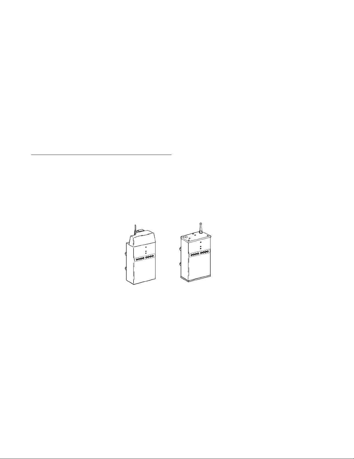
Description
The 6710 Access Point provides transparent, wireless
communications between a wired Ethernet LAN and
wireless stations. Figure 2-1 shows current designs;
information in this user’s guide applies to both designs.
Figure 2-1
6710 Access Points
6710 Access Point User’s Guide 2-1
SECTION 2 " Features and Functional Overview
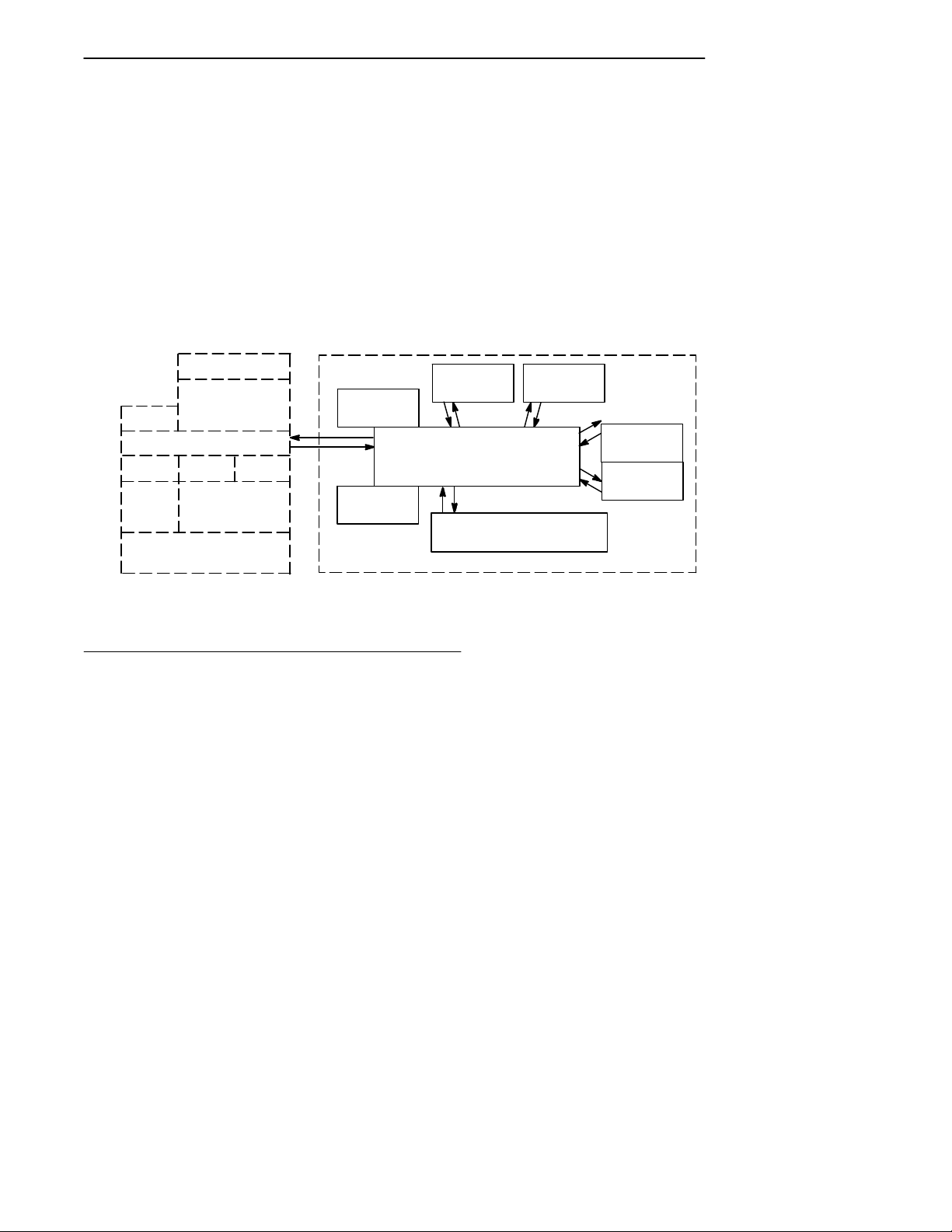
The access point functions as a 4-port translating bridge.
Functionality within the access point can be partitioned
into two major functional blocks: bridging functionality
and management functionality. Bridging functions pertain
to the forwarding of data through the access point.
Management functionality involves configuration, software
upgrade, and network management.
Figure 2-2 is a simplified diagram showing the functions
within the access point.
Management and Configuration Bridging
MIB
SNMP
DHCP
TFTP HTTP Telnet
File
System
RS-232 Diagnostics Port
Agent
TCP/IP
Device
Configuration
Forwarding
Database
Network
Organization
Figure 2-2
6710 Access Point Functions
Bridging Functionality
General Concepts
Bridges are common components in wired LANs. Bridges
are devices that join two or more LAN segments. This
provides the appearance of a single LAN segment to the
protocols and applications that operate within the LAN.
Port 2
(NIC 2)
Bridging
(Ethernet)
AUI 10BASE2 10BASE-T
Port 3
(NIC 1)
Port 1
Port 4
(OWL/IP)
Proxy ARP
2-2 6710 Access Point User’s Guide

SECTION 2 " Features and Functional Overview
Bridges operate at the Media Access Control (MAC)
sublayer of the Data Link Layer (Layer 2) of the
International Organization for Standardization (ISO)
protocol model. Operating at the MAC layer allows bridges
to operate transparently to commonly used network
protocols such as TCP/IP, Novell SPX/IPX, NetBEUI, and
DECnet.
In wired LANs, bridges do the following:
" Segment traffic for better efficiency and performance.
" Extend the reach of LANs when cable length or node
limits have been reached.
" Translate between different LAN types such as IEEE
802.3 Ethernet and 802.5 Token Ring.
A LAN environment normally consists of a collection of
nodes or stations, each identified by a unique 48-bit
physical address (also called an IEEE address or MAC
address). Data is sent on the LAN as frames or packets
that contain the source address of the station sending the
frame, and the destination address of the recipient station.
A bridge has at least two ports, each connected to a
different LAN segment. Bridges learn which source
addresses are generating traffic on each of their ports. If
the bridge receives a frame with a destination address
corresponding to a source address it has seen on another
port, it forwards the frame to the port. If it receives a
frame where the source and destination addresses are on
the same port, it ignores (drops) the frame, since the
destination node receives the original transmission.
Generally, if a bridge receives a frame for an unknown
destination address on any one port, it floods the frame on
all other ports.
6710 Access Point User’s Guide 2-3

SECTION 2 " Features and Functional Overview
Access Point Bridging Layer
The 6710 Access Point functions as a bridge with up to four
ports:
" An Ethernet port.
" One or two radio ports.
" An Open Wireless LAN/Internet Protocol (OWL/IP)
port.
The access point is a translating bridge because it forwards
frames between Ethernet and wireless media that have
unique physical and MAC protocol implementations. The
access point implements the basic learning and forwarding
functions of a simple wired LAN bridge. It also includes
additional functionality to address unique problems in
wireless LANs.
Significant functions supported at the bridging layer
include network organization, support for roaming and
power-managed stations, and programmable flooding levels.
Network Organization
Open wireless LAN networks may be complex, supporting:
" Small or large numbers of access points on a single
wired LAN backbone.
" Stations that roam between coverage areas and
employ power management to improve battery life.
More complex topologies include the following:
" Range extension through wireless access points, which
are not connected to the wired LAN backbone.
" Secondary LANs (connection of wired LAN segments
by wireless links).
" Mixed radio frequency (RF) media.
" Operation over multiple IP subnets.
" Multiple, independent wireless LANs on one wired
LAN backbone.
2-4 6710 Access Point User’s Guide

SECTION 2 " Features and Functional Overview
Access points automatically configure into a self-organized
network using a spanning tree topology. They
automatically reconfigure the network to maintain reliable
operation as devices are added or removed, or in the event
of some types of wired LAN failure. The spanning tree
provides efficient, loop-free forwarding of frames through
the network and rapid roaming of mobile stations within
the network.
The spanning tree is initiated by the super root, an access
point that coordinates the network and distributes common
system parameters to other access points and stations. The
super root is elected from a group of access points
designated at the time of installation. The election process
also occurs in the event of a super root failure, preventing a
single point of failure.
Forwarding
The bridge maintains a forwarding database of all physical
station addresses known to the access point, and the correct
port for each address. This database makes efficient
forwarding decisions in the bridging software.
The database is updated through monitoring addresses on
each port, and by messages exchanged between access
points when stations roam. The database also includes the
power management status of each station, supporting the
pending message feature of the network.
Pending Messages
Wireless stations may use power management to maintain
battery life. These stations wake up periodically to receive
messages that may have arrived while their radio was
powered down. The bridging software provides a pending
message delivery service, allowing frames to be held until
the station is ready to receive them.
6710 Access Point User’s Guide 2-5

SECTION 2 " Features and Functional Overview
Flooding Configurations
Standard LAN bridges flood frames on all ports when the
destination address is unknown. Additionally, many
network protocols use multicast addressing for connection
and status communications. A multicast frame is a special
type of frame destined for more than one physical address.
Standard bridges always flood multicast frames.
Most wireless media supported in the access point operate
at lower media speeds than Ethernet. Indiscriminate
flooding from a busy Ethernet backbone to a wireless
medium can consume a substantial portion of the available
wireless bandwidth. This reduces system performance even
though flooded frames are frequently not intended for
stations on a given wireless segment.
To allow performance tuning, the access point provides
separate flooding control options for both unicast (single
physical address) and multicast frames. Access points
serving as designated bridges connecting wired LAN
segments may be configured to use different flooding
settings than access points serving only wireless stations.
Two of the wireless media supported in the access point —
synthesized UHF (S-UHF) and 900 MHz — provide reliable
attach mechanisms, which guarantee that wireless stations
are always in the access point’s forwarding database.
Unicast flooding is never required for these stations.
The Wireless LAN Interoperability Forum (WLIF) 2.4 GHz
option also provides a reliable attach mechanism for
stations using the NORANDRNetwork Layer (NNL)
terminal emulation network protocol. Multicast flooding
levels are set for individual networks based on the needs of
wireless stations to receive multicast frames. For networks
with IP wireless stations only, the Proxy ARP Server
provides an option to enabling multicast flooding.
2-6 6710 Access Point User’s Guide

SECTION 2 " Features and Functional Overview
Proxy ARP Server
The Proxy ARP Server is an advanced flooding control
capability for stations using IP. An ARP (Address
Resolution Protocol) is a type of multicast message used to
determine the physical (MAC) address of a station using a
specific IP address. When Proxy ARP is enabled, the IP
addresses of stations using IP are included in the
forwarding database. If the destination IP address matches
an entry in the forwarding database, the ARP is sent to the
physical unicast address matching that IP address.
To allow customization of this capability to optimize
performance, the server operates in one of the following
modes:
" No flooding.
" Delayed flooding.
" Normal flooding.
Proxy ARP Server is discussed in more detail in Section 4,
“Configuration.”
Bridge Ports
The access point has the following physical ports:
" An Ethernet port.
" Two PC card slots capable of accepting a variety of
wireless Network Interface Cards (NICs).
The access point also has a logical OWL/IP port.
Ethernet Port
The Ethernet port can be configured to support 10BASE-T
twisted pair , 10BASE2 thinnet, or an AUI connection. The
AUI connection can support 10BASE5 thicknet or 10BASEF
fiber optic connections with the appropriate media
adapters.
6710 Access Point User’s Guide 2-7

SECTION 2 " Features and Functional Overview
The physical connections are on the bottom panel of the
access point. The desired Ethernet medium is selectable
through the device configuration menus. Section 3,
“Installation,” has more information about connecting the
access point to Ethernet media. Section 4, “Configuration,”
describes how to set the medium through the configuration
menus.
Ethernet Port Filters
The Ethernet port can be configured to support a variety of
preconfigured and custom input filters. Access points are
commonly installed on LANs that carry traffic for wired and
wireless devices. Setting filters prevents unnecessary
traffic from the wired LAN from being forwarded onto the
wireless medium. This is important because common
wireless technologies operate at data rates below Ethernet
speeds.
Normally, filters are set to pass traffic known to be (or
likely to be) destined for wireless stations, and drop traffic
not destined for stations requiring wireless connectivity.
Filtering occurs in the Ethernet driver software that
controls low level operation of the Ethernet ports,
minimizing involvement of other functions when
unnecessary frames are received. In most installations, the
predefined filters are used. The default access point
configuration sets no filters. Filter setup is discussed in
more detail in Section 4, “Configuration.”
Filtering and flooding control (described on page 2-6) are
complimentary but have different functions. Filters allow
frames to be eliminated based upon content of the frame,
usually the network protocol header fields within the frame.
For example, filters can be set to eliminate some or all IP
traffic or Novell IPX traffic.
2-8 6710 Access Point User’s Guide

SECTION 2 " Features and Functional Overview
Filtering occurs regardless of whether the destination
address is in the forwarding database. Using filters can
improve the performance of the access point and prevent
undesired frames from being forwarded to wireless stations
attached to the access point.
Flooding decisions are made after frames have been
received on a port and filtered. Flooding settings determine
how the access point forwards frames to destination
addresses not in the forwarding database.
Radio Ports
Each of the two radio ports in the access point are a
connection into a LAN segment consisting of all wireless
stations and access points that use the same wireless
technology, are within wireless communications range of
the access point, and are configured to communicate
together .
The two PC card slots are intended for wireless NICs and
are designated as NIC1 and NIC2. Internally, they are
configured as Port 3 and Port 2, respectively. The following
wireless options are currently supported:
" WLIF (2.4 GHz).
" 900 MHz.
" 450 MHz S-UHF.
The different media options provide alternative coverage
and throughput tradeoffs. Radio media options are
described in more detail in Appendixes B, C, and D.
The access point also supports combinations of two adapters
for operation in mixed media systems; or , for WLIF radios,
a wireless access point capability. The following dual radio
configurations are supported:
" WLIF and 900 MHz.
" WLIF and S-UHF.
" WLIF and WLIF (limited to Master/Slave
configuration for wireless access points).
6710 Access Point User’s Guide 2-9

SECTION 2 " Features and Functional Overview
Configuration of individual radio options and the WLIF
wireless access point configuration are discussed in Section
4, “Configuration.”
OWL/IP Port
The OWL/IP port is a logical port used in installations
where the wireless infrastructure is required to operate
across multiple IP subnets; that is, in installations where
IP routers are used.
The OWL/IP port is an advanced capability that allows
stations supporting IP and nonroutable protocols such as
NNL (used in some terminal emulation installations) to
roam without losing connectivity when a wireless LAN
installation must extend over multiple IP subnets. In some
cases, OWL/IP may also provide connectivity in larger ,
routed networks when roaming between IP subnets is not
required, but where it is desirable to configure a single
wireless network across router boundaries.
OWL/IP uses General Router Encapsulation (GRE), a
registered protocol from the TCP/IP protocol suite. GRE
allows frames destined for stations on a different IP subnet
to be encapsulated with an IP address that passes
transparently through routers. Encapsulation is also
sometimes referred to as tunneling.
To simplify configuration, OWL/IP functionality is treated
as an additional port within the access point architecture.
It is a logical port in that there is no physical radio or wired
LAN port associated with OWL/IP.
Encapsulated frames may be sent through any of the three
physical ports. Access points separated by one or more
routers may be thought of as originating and receiving
nodes on the two sides of a tunnel that is established
through the router .
2-10 6710 Access Point User’s Guide

SECTION 2 " Features and Functional Overview
The forwarding database entry for a station on the other
side of the tunnel includes the physical port (NIC1, NIC2,
or Ethernet) the frame should be forwarded through, and
an indication that encapsulation is required. The receiving
access point on the other side of the tunnel de-encapsulates
the frame and then forwards it on the correct physical port.
OWL/IP is described in more detail in Section 4,
“Configuration,” and Appendix E, “OWL/IP.”
Configuration and Management
Configuration
The access point can be configured through a local RS-232
connection, or remotely through a TCP/IP connection. The
access point includes a command monitor and menu driven
configuration with online help. The command monitor and
file system configuration are contained in permanent
read-only memory (ROM) within the access point, and can
be accessed through the RS-232 diagnostics port even if
software is not loaded in the access point.
Most access point functionality is provided by the software
stored within the file system. Configuration parameters
are stored in nonvolatile EEPROM memory, and are
maintained in the event of power loss.
Diagnostics and Configuration Port
An RS-232 configuration port is provided for direct access to
the access point’s command monitor and configuration
menus. Access through the diagnostics port is
password-protected for security.
6710 Access Point User’s Guide 2-11

SECTION 2 " Features and Functional Overview
The port uses a standard PC AT style cable, and operates at
speeds up to 57.6 Kbps. Configuration using this port is
described in Section 4, “Configuration.”
Remote Access
Remote access is available over TCP/IP connections using
Telnet or Hypertext Transfer Protocol (HTTP) for
configuration management, and Simple Network
Management Protocol (SNMP) for network management.
TCP/IP
The access point supports remote access through a Request
for Comments (RFC) compliant TCP/IP stack. Before initial
usage, the stack must be initially configured with an IP
address and an optional default router through the RS-232
diagnostics port. Alternatively, the access point may be
configured with a Dynamic Host Configuration Protocol
(DHCP) server name. The access point then obtains its IP
address, default router , and subnet mask from a DHCP
server .
DHCP Client
The access point contains a DHCP client, allowing it to
receive an IP address over the network. The DHCP client
supports temporary and permanent leases. It also accepts
permanent leases from a Bootstrap Protocol (Bootp) server .
See Section 4, “Configuration,” for further detail on DHCP
operation.
Telnet
Telnet may be used to access the access point’s
configuration menus. The command interface is identical to
the command interface through the diagnostics port. See
Section 4, “Configuration,” for more information about
access through Telnet.
2-12 6710 Access Point User’s Guide

SECTION 2 " Features and Functional Overview
HTTP
The access point supports configuration using HTTP from a
workstation equipped with a Web browser . Internet
Explorer or Netscape Navigator is recommended. See
Section 4, “Configuration,” for more information about
access through a Web browser .
Electronic Software Distribution
The access point supports electronic software distribution,
which allows software upgrades after installation. The
access point provides a dual bank file system with one
active bank and one inactive bank. It operates from the
active bank, allowing software upgrades to be stored in the
inactive bank. This enables upgrades to be loaded while
the access point is operating.
The upgrade can be started immediately after downloading
by swapping the active and inactive banks and rebooting.
The access point can also be programmed to load the new
software at a later time, such as after all access points have
been upgraded or during a time of little system activity.
TFTP Client and Server
Software downloads are accomplished using the Trivial File
Transfer Protocol (TFTP), another member of the IP suite.
Each access point contains a TFTP client and server . The
TFTP client allows the access point to obtain software
updates from a TFTP server . The server can be an access
point configured with the TFTP server enabled, or another
network workstation with TFTP server capability.
Scripting
The access point supports a scripting capability that
automates most of the software download process. Scripts
can be uploaded to the access point through Telnet or
SNMP.
6710 Access Point User’s Guide 2-13

SECTION 2 " Features and Functional Overview
Network Management
The access point is instrumented for network management,
with variables defined in the Management Information
Base (MIB). The MIB is SNMP V1 compliant.
Management information can be accessed through the
SNMP agent. The MIB may be ordered separately and
compiled for any SNMP network management platform.
Additional capabilities are supported in the OWLView
network management application for HP OpenView.
Appendix G, “MIB,” contains the 6710 Access Point MIB.
Consult the following documentation for more information
on network management:
" NORAND Open Wireless LAN with HP OpenV iew for
Windows User’s Guide (961-051-009)
" OWLV iew for HP OpenView for UNIX User’s Guide
(961-051-011)
" OWLV iew for HP OpenView for Windows User’s Guide
(961-051-010)
Sample Configuration
Figure 2-3 shows a sample network configuration. It also
shows access points providing additional coverage and
wireless links to secondary Ethernet LANs.
"
NOTE: Consult Appendix D, “S-UHF Specifications and Antennas,” for
network configuration limitations for S-UHF systems.
2-14 6710 Access Point User’s Guide

SECTION 2 " Features and Functional Overview
LAN Server
6710 Access Point
6710 Access Point
(Designated Bridge)
Secondary Ethernet LAN
Desktop
Host
6710 Access Points
PEN*KEYR6400
Computer
Terminal Emulation
Gateway
Distribution LAN
Wireless Hop
Notebook
(WLIF)
PEN*KEY 6400
Computer
Figure 2-3
Sample Network Configuration
6710 Access Point User’s Guide 2-15

SECTION 2 " Features and Functional Overview
Components
Figure 2-4 shows access point components, described on the
following pages. Not shown is the mounting bracket, which
attaches the access point to a wall or ceiling.
2-16 6710 Access Point User’s Guide
Figure 2-4
Access Point Components

SECTION 2 " Features and Functional Overview
1. Protective cover. The cover protects two Type II or
Type III PC card slots. Figure 2-5 shows where the
slots are located.
1
1
1. PC card slots
Figure 2-5
PC Card Slots
2. Indicator lights. Four pairs of indicator lights
(LEDs) on the front panel show the status of the
access point. During the power-up sequence, the
lights show the results of the power-up self diagnostics
and provide information about the operating status.
After the power-up sequence, the lights show the
current operating status and indicate if a problem
exists. Section 6, “Indicator Lights,” describes the
lights in detail.
6710 Access Point User’s Guide 2-17

SECTION 2 " Features and Functional Overview
3. Rubber feet. Four nonskid rubber feet provide a
stable base for the access point when you place it on a
desktop or other horizontal surface.
When the mounting bracket is installed for an access
point mounted vertically or on the ceiling, the rubber
feet provide a small amount of tension to the bracket
to help hold it in place.
4. AC INPUT. The AC INPUT connector is a standard
IEC type, three-prong AC input connector . The power
cord attaches to this connector . The internal power
supply is an autosensing international power supply.
It accepts a source voltage between 85 and 264 V ac,
with a frequency between 47 and 63 Hz.
5. 10 BASE 2. The 10 BASE 2 port is a standard BNC
port through which the access point connects to
10BASE2 Ethernet (thinnet).
6. 10 BASE T. The 10 BASE T port is a standard RJ45
port through which the access point connects to
10BASE-T (UTP) Ethernet.
7. AUI. The AUI port is a 15-pin, D-subminiature
(D-sub) port. The access point connects to an AUI
network adaptor through this port, for connection to
10BASE5 Ethernet (thicknet). Appendix F, “Port and
Cable Pin-Outs,” contains pin definitions.
"
NOTE: Section 3, “Installation,” shows how to connect the access point to
10BASE2, 10BASE5, and 10BASE-T.
8. DIAG. The DIAG port is a 9-pin D-sub
communication port that communicates at RS-232
levels. Use this port to configure the access point,
download new software, and retrieve statistics.
Appendix F contains pin definitions.
2-18 6710 Access Point User’s Guide

Accessories
Power Cord
The power cord connects the access point to the wall outlet.
The following chart lists power cord part numbers.
Country Part Number
Australia 321-472-001
Denmark 321-501-001
Europe 321-473-001
Italy 321-471-001
Germany 321-515-001
United Kingdom 321-474-001
United States 321-054-001
SECTION 2 " Features and Functional Overview
Industrial Locking Mounting Bracket
The Industrial Locking Mounting Bracket “locks” the access
point into the bracket. This bracket is recommended for
installations where vibration, shaking, or other movement
can dislodge the access point from its mount.
Item Part Number
Mounting kit 203-386-001
6710 Access Point User’s Guide 2-19

SECTION 2 " Features and Functional Overview
2-20 6710 Access Point User’s Guide

Section 3
Installation
" " " " " " " " " " " " " " " " " " " " " " " " " " " "
This section describes how to:
" Check the access point’s default configuration.
" Prepare for the installation.
" Collect the networking equipment you need.
" Find the best location.
" Connect to the Ethernet medium.
" Install PC cards.
" Apply power .
Checking the Default Configuration
The access point is shipped with default settings for system
software parameters, which are listed in Section 4,
“Configuration.” You may need to change some default
settings to achieve a more efficient configuration for your
site. See Section 4 for information about reconfiguring the
access point. The access point should be properly
configured before it is connected to the network.
6710 Access Point User’s Guide 3-1

SECTION 3 " Installation
Preparing for the Installation
"
NOTE: Someone who knows and understands all applicable local building
codes and is proficient with the tools and equipment used to install
FCC Class B electromechanical devices should physically install the
access point.
Before you install the access point, unpack it and inspect it
for damage or missing parts. Save all the paperwork you
received. If the access point appears to be damaged, contact
the Customer Response Center for instructions on
returning the unit for replacement.
The shipment contains the access point with FLASH and
the following items:
" Mounting bracket
" AC power cord
" Warranty card
Collecting the Equipment
Before you install the access point onto the network, collect
the equipment you will need.
Ethernet LAN Components
The access point directly connects to 10BASE2, 10BASE-T,
or 10BASE5 Ethernet medium. Consult a cabling reference
for maximum run lengths and node limits for Ethernet
wiring.
3-2 6710 Access Point User’s Guide

SECTION 3 " Installation
10BASE2 Components
10BASE2 components include a T-connector, a cable
terminator , and the proper lengths of 10BASE2 coax cable.
The 10BASE2 T-connector (Figure 3-1) attaches to the
access point’s 10BASE2 port, and connects the access point
to the middle or end of 10BASE2 cable.
Figure 3-1
T-Connector
A cable terminator (Figure 3-2) attaches to the
T-connector. It is required for a device connected to the end
of 10BASE2 cable. The terminator properly terminates the
network cable to maintain proper impedance. Proper
termination is necessary for reliable Ethernet operation.
Figure 3-2
Cable Terminator
10BASE -T Component
10BASE-T coax cable is normally used to connect the
access point to an Ethernet hub. The cable has an RJ45
plug on each end (Figure 3-3).
Figure 3-3
Cable With RJ45 Plugs
6710 Access Point User’s Guide 3-3

SECTION 3 " Installation
10BASE5 Components
10BASE2 components include the proper lengths of
10BASE5 coax cable, an AUI drop cable (less than or equal
to 50 feet/15 meters long), and a transceiver . Two types of
transceivers are the intrusive N-Series transceiver and the
nonintrusive vampire tap.
The N-Series transceiver (Figure 3-4) is a T-shaped
connector with a 15-pin AUI port and two type N
connectors. This transceiver is intrusive because network
service is disrupted while the coaxial cable is cut and a
threaded N-series connector placed on each end of the cable.
A 10BASEF (fiber optic) adapter may be attached directly
to the AUI connector .
The vampire tap is an insulation-piercing clamp device that
clamps onto the coaxial cable (Figure 3-5). The vampire tap
pierces the coaxial cable’s insulation and makes contact
with the shield and inner conductor without cutting the
cable.
3-4 6710 Access Point User’s Guide
Figure 3-4
N-Series Transceiver

SECTION 3 " Installation
Figure 3-5
Vampire Tap
Communication Equipment
You can access the access point’s system software
configuration menus locally through the unit’s DIAG port,
or remotely through a Telnet session or Web browser.
Local DIAG Port Access
For local access, you need the following:
" Third-party communications software terminal
emulation package with Y-modem capability (such as
PROCOMM PLUS by DataStorm Technologies, Inc.).
Install the program according to its user guide.
" PC (personal computer) station, which should meet
the requirements outlined in the user guide for the
terminal emulation program.
" Cable to connect the PC to the access point’s DIAG
port. The following chart lists cables.
6710 Access Point User’s Guide 3-5

SECTION 3 " Installation
Telnet
You need the following to access the configuration menus
through a Telnet session:
" PC or workstation with an installed and configured
" Telnet VT emulator (TNVT) installed on the PC.
" IP address for the access point. See Section 4 for more
Web Browser
The access point’s configuration menus are designed for
HTML Level 2.0 or higher . You need the following to access
the configuration menus through a Web browser:
For this PC Port Use Cable Part Number
9-pin 226-106-001 (null modem cable)
25-pin 321-355-001
network interface card and a Telnet application. Y ou
can also use a host capable of acting as a Telnet client.
information about IP addresses.
" Graphical browser application.
" Internet or local network connection.
" IP address for the access point. See Section 4 for more
information about IP addresses.
Network Management Platform
To manage the system through a network management
platform, you need the platform (such as OpenView for
Windows by Hewlett-Packard) installed on a network
management station using SNMP. The station must meet
the requirements outlined in the platform’s user guide.
3-6 6710 Access Point User’s Guide

Finding the Best Location
Site Survey
Intermec strongly recommends that Intermec or certified
providers conduct a site survey to determine the ideal
locations for all of your network components. A proper site
survey requires special equipment and training. A site
survey provides an installation recommendation that
addresses various factors, which can affect the performance
of your wireless LAN system.
General Installation Guidelines
Coverage in most sites requires a network of access points
to be installed. Radio coverage varies greatly with factors
such as building construction, number and type of
obstructions in the signal path, and the RF media in use.
Additional factors related to the intended use of the system
also dictate installation practices. The following general
practices should be followed in any installation:
SECTION 3 " Installation
" Locate access points centrally within areas requiring
coverage.
" Try to position the access point so its indicator lights
are visible. The lights are useful for troubleshooting
the installation.
" Position antennas below roof trusses and away from
I-beams, racks, or other structures and obstructions.
" Overlap access point coverage areas to avoid coverage
holes.
" Install wired LAN cabling within node limit and cable
length limitations.
6710 Access Point User’s Guide 3-7

SECTION 3 " Installation
" Ensure that a power outlet is within 6 feet of the
access point. An uninterruptable power supply is
recommended when the ac power system is not
reliable.
" Ensure that LAN and ac cables can reach the access
point after you install it. Leave sufficient room
around the access point so you can easily attach and
remove cables.
" Do not locate an access point with the S-UHF radio
option in a computer room. RF emissions from the
higher speed processors in current-generation
computers may reduce system range.
Mounting the Access Point
You can mount the access point horizontally on a tabletop,
vertically on a wall or post, or on the ceiling.
Horizontal (Tabletop) Mount
1. Remove the mounting bracket from the bottom of the
access point. The bracket is not needed for a tabletop
installation.
2. Set the access point in position. The unit rests
securely on four rubber feet that keep it from slipping
out of place.
3. Make all Ethernet connections. See “Connecting to
Ethernet” on page 3-10.
4. Make all power connections. See “Applying Power” on
page 3-20.
5. Watch the indicator lights to verify that the access
point is working properly. See Section 6, “Indicator
Lights,” for help.
3-8 6710 Access Point User’s Guide

SECTION 3 " Installation
Vertical and Ceiling Mounts
See Figure 3-6 and the procedure following it.
"
NOTE: If mounting the access point on a hollow wall, secure the mounting
plate to a 3/4” (thick) plywood base by four 1” X 1/4” nuts, bolts, and
washers. Anchor the plywood base to two separate wall studs by
four 2” X 1/4” diameter lag screws (two lag screws in each stud).
6.00"
1.00"
2.00"
1.00"
2.00”
1.00"
Figure 3-6
Mounting Bracket
6710 Access Point User’s Guide 3-9

SECTION 3 " Installation
1. Inspect where the access point will be mounted and
2. Remove the mounting plate from the bottom of the
3. Using the mounting plate as a template, mark where
4. Attach the access point mounting plate to the wall or
5. Reattach the access point to the mounting plate.
6. Make all Ethernet connections. See “Connecting to
7. Make all power connections. See “Applying Power” on
8. Watch the indicator lights to verify that the access
determine what hardware is needed. Different
surfaces such as drywall, wood, and concrete block
require different mounting hardware. For this reason,
a universal mounting bracket is included with the
access point.
access point.
the anchors that secure the mounting plate to the
surface should be located.
ceiling with 2I x 1/4I diameter lag screws or bolts,
depending upon the surface. The mounting plate
must be secured to the surface by at least four
anchors, one on each corner .
Ethernet.”
page 3-20.
point is working properly. See Section 6, “Indicator
Lights,” for help.
"
NOTE: An optional locking kit is available. See Section 2, “Features and
Functional Overview,” for more information.
Connecting to Ethernet
The following pages show how to connect the access point to
10BASE2, 10BASE5, and 10BASE-T Ethernet.
3-10 6710 Access Point User’s Guide

SECTION 3 " Installation
10BASE2 Ethernet
The access point connects to the end or middle of the
10BASE2 cable segment.
"
NOTE: Cable lengths between network devices on the 10BASE2 Ethernet
LAN must meet ANSI/IEEE standards.
End of Segment
See Figure 3-7 and the procedure following it.
10 BASE 2
AC INPUT
100/240 VAC
10 BASE T
1. Cable terminator (50 ohm)
2. T-connector
3. 10BASE2 cable
AUI
DIAG
31 2
Figure 3-7
End of 10BASE2 Segment
1. Plug the T-connector (2) into the 10 BASE 2 port.
2. Plug one end of the Ethernet cable (3) into an open
end of the T-connector. Align the notches in the cable
end with the posts on the T-connector, push the cable
in, and twist one-quarter turn.
3. Plug the cable terminator (1) into the other end of the
T-connector.
6710 Access Point User’s Guide 3-11

SECTION 3 " Installation
Middle of Segment
See Figure 3-8 and the procedure following it.
10 BASE 2
AC INPUT
100/240 VAC
10 BASE T
2
1. 10BASE2 cable
2. T-connector
AUI
DIAG
11
Figure 3-8
Middle of 10BASE2 Segment
1. Plug the T-connector (2) into the 10 BASE 2 port.
2. Plug one end of the Ethernet coaxial cable (1) into an
open end of the T-connector. Align the notches in the
cable end with the posts on the T-connector, push the
cable in, and twist about one-quarter turn.
3. Plug the end of another Ethernet coaxial cable
segment into the other open end of the T-connector.
3-12 6710 Access Point User’s Guide

SECTION 3 " Installation
10BASE5 Ethernet
The access point connects to 10BASE5 through an N-Series
transceiver or vampire tap.
"
NOTE: Cable lengths between network devices on the 10BASE5 Ethernet
LAN must meet ANSI/IEEE standards.
N- Series Transceiver
See Figure 3-9 and the following procedure.
1. Attach one end of the drop cable (1) to the AUI port.
2. Route the drop cable to the 10BASE5 cable (4) and
determine a suitable spot to cut the cable and attach
the transceiver (3).
3. Attach the transceiver to the 10BASE5 cable, then
connect the other end of the drop cable to the AUI port
(2) on the transceiver .
Vampire Tap
See Figure 3-10 and the following procedure.
1. Attach one end of the drop cable (1) to the AUI port.
2. Route the drop cable to the 10BASE5 cable and
determine a suitable spot on the cable to attach the
vampire tap (3).
3. Attach the vampire tap to the 10BASE5 cable, then
connect the other end of the drop cable to the AUI port
(2) on the tap.
6710 Access Point User’s Guide 3-13

SECTION 3 " Installation
10 BASE 2
AC INPUT
100/240 VAC
10 BASE T
AUI
1
2
DIAG
3
3-14 6710 Access Point User’s Guide
4
1. Drop cable
2 15-pin AUI port
3. N-Series transceiver
4. 10BASE5 coax
Figure 3-9
N-Series Transceiver
4

SECTION 3 " Installation
10 BASE 2
AC INPUT
100/240 VAC
10 BASE T
AUI
1
2
DIAG
3
1. Drop cable
2. 15-pin AUI port
3. Vampire tap
4. 10BASE5 coax
Figure 3-10
Vampire Tap
6710 Access Point User’s Guide 3-15
4
4

SECTION 3 " Installation
10BASE-T Ethernet
See Figure 3-11 and the procedure following it.
10 BASE 2
AC INPUT
100/240 VAC
1
10 BASE T
1. Cable with RJ45 plugs
2. RJ45 jack (or hub port)
AUI
Figure 3-11
10BASE-T
DIAG
1. Plug the cable with RJ45 jacks (1) into the 10 BASE T
port.
2. Plug the other end of the cable into RJ45 jack or hub
port (2).
3-16 6710 Access Point User’s Guide

Installing PC Cards
The following pages describe how to install WLIF, 900 MHz,
and S-UHF PC cards.
WLIF
The WLIF radio option is a Type III PC card that can be
installed in either slot. To install the card, see Figure 3-12.
1
SECTION 3 " Installation
2
3
4
5
4
1. Nonskid rubber feet (4)
2 Access point (no radio)
3. PC card (RM180)
4. Antenna cable
5. End plate
6. 4--40 captive thumb screws
7. Hex nut and lock washer (supplied with antenna cable)
Figure 3-12
WLIF PC Card Assembly
6710 Access Point User’s Guide 3-17
6
7

SECTION 3 " Installation
900 MHz
The 900 MHz radio option is a Type III PC card that can be
installed in either slot. To install the card, see Figure 3-13.
1
2
3
4
4
1. Nonskid rubber feet (4)
2 Access point (no radio)
3. PC card (RM160)
4. Antenna cable
5. End plate
6. 4--40 captive thumb screws
7. Hex nut and lock washer (supplied with antenna cable)
5
Figure 3-13
900 MHz PC Card Assembly
6
7
3-18 6710 Access Point User’s Guide

SECTION 3 " Installation
S-UHF
The S-UHF radio option is a Type II PC card that can only
be installed in the left-hand slot (with LEDs facing down).
To install the card, see Figure 3-14.
1
2
3
4
5
1. Nonskid rubber feet (4)
2 Access point (no radio)
3. Sliding latch (open for RM11 1adapter)
4. PC card (RM111)
5. Flex circuit
6. RM1 11 adapter
7. Radio bracket
8. Conductive washer
9. End plate
10. 4--40 captive thumb screws
11. 4--40 x .25 PH
12. Antenna adapter
6
9
7
8
10
11
12
Figure 3-14
S-UHF PC Card Assembly
6710 Access Point User’s Guide 3-19

SECTION 3 " Installation
Applying Power
B
CAUTION: NEVER remove the cover of the access point with power
applied. ALWAYS make the access point connection before
making the connection at the source (“load to source”).
Damage to the radio or other devices can occur with the cover
removed.
"
NOTE: Connect the access point to an uninterruptable power source — a
power source that cannot be inadvertently turned off or otherwise
disconnected.
Power is applied to the access point through the grounded
AC INPUT connector . See Figure 3-15 and the following
procedure.
1. Plug the receptacle end of the power cord (1) into the
AC INPUT connector .
2. Insert the three-prong plug on the other end of the
power cord (2) into a grounded power outlet.
3. See Section 6, “Indicator Lights,” for descriptions of
the indicator lights.
3-20 6710 Access Point User’s Guide

SECTION 3 " Installation
10 BASE 2
AC INPUT
100/240 VAC
1
10 BASE T
1. Receptacle on power cord
2. Three-prong plug
AUI
2
Figure 3-15
AC Power Input Connection
DIAG
6710 Access Point User’s Guide 3-21

SECTION 3 " Installation
3-22 6710 Access Point User’s Guide

Section 4
Configuration
" " " " " " " " " " " " " " " " " " " " " " " " " " " "
This section describes how to:
" Create a local DIAG port, Telnet, and Web browser
session with the access point.
" Access the access point’s FLASH and ROM.
" Set up the access point through its configuration
menus.
You can configure the access point locally through its DIAG
port, or remotely through Telnet or a Web browser. The
following chart shows the sessions you can use to do other
tasks.
T ask DIAG Port Telnet Browser
Change configuration passwords
Modify the configuration Ö Ö Ö
Upgrade FLASH Ö Ö
Check the FLASH version Ö Ö
Access ROM Ö
Check the ROM version Ö
Use online help Ö Ö Ö
Ö Ö Ö
6710 Access Point User’s Guide 4-1

SECTION 4 " Configuration
Only one type of session can be running at a time. For
example, if someone starts a Telnet session while someone
else is configuring the access point through its DIAG port,
the configuration through the DIAG port will terminate.
Creating a Local DIAG Port Session
In summary, you establish a local DIAG port session with
the access point through a VT100 terminal emulation
program. Most general purpose communications software
(such as PROCOMM PLUS) supports this emulation.
To create a session, see Figure 4-1 and the procedure
following it. You should carefully review the procedure first
to become familiar with the process.
4-2 6710 Access Point User’s Guide

SECTION 4 " Configuration
1
2
3
10BASE2
AC INPUT
100/240 VAC
10BASET
AUI
DIAG
1. PC with terminal emulation program
2. Cable: 321-355-001 for a 25-pin PC COM port
or
Cable: 226-106-001 for a 9-pin PC COM port
(standard null modem cable)
3. 6710 Access Point DIAG port
Figure 4-1
Local Session
1. Ensure the terminal emulation program is installed
on the PC.
2. With both the PC and access point powered OFF,
connect the communication cable to the appropriate
PC COM port.
6710 Access Point User’s Guide 4-3

SECTION 4 " Configuration
3. Connect the other end of the communication cable to
the DIAG port on the access point. Turn the PC on.
4. After the PC boots, start the terminal emulation
program.
5. Set the terminal emulation program’s options
according to what you want to do: Access the
configuration menus, or access the ROM command
monitor .
Accessing the Configuration Menus
1. Set the terminal emulation parameters in your
communications software. If you are configuring this
access point for the first time, set the parameters to
the access point’s default settings:
9600, 8N1, full duplex
If you have already changed the default settings, set
the parameters to those you set in FLASH mode
through the configuration menus.
2. Plug the access point into the outlet. These messages
appear:
QXS6700K <version> <date>
<Press any key within 5 seconds to enter the ROM monitor>
Executing file USTART29.BIN from segment <segment number>
Quickly press a key to perform configuration before startup
Starting system
3. To access the configuration menus, wait until you see
the message “Quickly press a key to perform
configuration before startup.” Press any key to access
the configuration menus.
4. See “Configuring the Access Point” on page 4-12.
4-4 6710 Access Point User’s Guide

SECTION 4 " Configuration
Accessing the ROM Command Monitor
1. Set the terminal emulation parameters in your
communications software. If you are configuring this
access point for the first time, set the parameters to
the default settings for ROM mode:
9600, 8N1, full duplex
If you have already changed the default settings, set
the parameters to those you set in ROM mode through
the ROM command monitor .
2. Plug the access point into the outlet. These messages
appear:
QXS6700K <version> <date>
<Press any key within 5 seconds to enter the ROM monitor>
Executing file USTART29.BIN from segment <segment number>
Quickly press a key to perform configuration before startup
Starting system
3. Press any key within 5 seconds of the first ROM
message.
Note that if the access point is in Power-Up Quiet
mode (versus Power-Up Normal mode, the default
setting), the ROM messages do not display. More
information about Power-Up Quiet (PQ) mode and
Power-Up Normal (PN) mode starts on page 5-27 in
Section 5, “Software Download.”
4. See page 5-22 in Section 5, “Software Download,” for
information about the ROM command monitor .
6710 Access Point User’s Guide 4-5

SECTION 4 " Configuration
Creating a Telnet Session
Before you can configure the access point through Telnet,
you must connect the unit to the Ethernet cable. (See
Section 3, “Installation,” for help.) You must also perform
initial configuration through the DIAG port to:
" Set an IP address or DHCP server name. You should
also configure a subnet mask and IP router address.
" Set the Ethernet cable type.
"
NOTE: The access point includes an autodetect feature that senses the
Ethernet medium if traffic is present. If no traffic is present on the
cable, the system software defaults to 10BASE-T. For most
installations, it is recommended that you explicitly set the Ethernet
type.
The access point must go through its boot sequence before
you can create a Telnet session. If you reboot the unit while
in a session, the session terminates. You can create a new
session after the unit reboots.
To create a Telnet session, see Figure 4-2 and the procedure
following it.
Ethernet LAN
1. PC or workstation with Telnet VT emulator (TNVT)
2. 6710 Access Point
4-6 6710 Access Point User’s Guide
Telnet
1
2
Figure 4-2
Telnet Session

1. Ensure the access point is connected to the Ethernet
cable, and has an assigned IP address and cable type.
2. Ensure the PC or workstation has an installed and
configured Ethernet interface card.
3. Ensure the Telnet VT emulator is installed on the PC
or workstation.
4. Open a new Telnet session on the PC or workstation.
5. Enter the access point’s IP address in the host name
or IP address field.
6. See “Configuring the Access Point” on page 4-12.
Default and Site Settings
The access point is factory configured with the default
settings listed in the following charts. You may need to
change the defaults to match the way your system is set up.
You can record your site’s settings in the table for reference.
SECTION 4 " Configuration
TCP/IP
Option Default Site Setting
IP Address 0.0.0.0
IP Subnet Mask 255.255.255.0
IP Router 0.0.0.0
IP Frame Type DIX
DHCP Enabled, if IP Ad-
dress is zero
DHCP Server Name Norand DHCP Server
Auto ARP Minutes 5
6710 Access Point User’s Guide 4-7

SECTION 4 " Configuration
Security
Option Default Site Setting
Password CR52401
Service Password Enabled
Advanced Password
“” (empty string)
Bridge
Option Default Site Setting
Serial Number (Read-only)
Lan ID 0
[Root]
Root Priority 1
[Global Radio]
UHF Rfp Threshold
Set Globally Disabled
Value 70
UHF Frag Size
Set Globally Disabled
Value 250
Falc Frag Size
Set Globally Disabled
Value 250
A wake Time
Set Globally Disabled
Value 0
[Global Flooding]
Inbound
Multicast Primary
Unicast Disabled
Outbound to Secondaries
Multicast Disabled
Unicast Disabled
Outbound to Stations
Multicast Disabled
Unicast Disabled
4-8 6710 Access Point User’s Guide

Option Site SettingDefault
[Ports]
Ethernet port:
Name omde
MAC Address (Unique number)
Status Enabled
Hello Period 2 seconds
[Ethernet]
OWL Frame Type DIX
Cable Type Auto Detect
[Static Addresses] 00:00:00:00:00:00
[Normal RX Filter]
[Frame Types]
Action Pass
Scope Unlisted
[SubTypes 1]
Action Pass
SubType (Various)
Scope (Various)
[SubTypes 2]
Action Pass
SubType DIX--IP--TCP--Port
Scope 00 00
[Advanced RX Filter]
[Expressions]
ExprSeq 0
Offset 0
Op EQ
Value Id 0
Action And
[Values]
Value 0
[Bridging]
Bridge Priority 1
Status Enabled
Flood Register Disabled
SECTION 4 " Configuration
6710 Access Point User’s Guide 4-9

SECTION 4 " Configuration
Option Site SettingDefault
WLIF radio port:
Name omdpxma
MAC Address (Unique number)
Status Enabled
Hello Period 2 seconds
[WLIF]
Security Id NORANDOWL
Node Type Master
[Master Parms]
Channel 1
Subchannel 1
Wireless Hops Disabled
MAC Config Default
[Manual MAC Parms]
Hop Period 200 ms
Beacon Frequency 2
Deferral Slot Default
Fairness Slot Default
Fragment Size 310
Transmit Mode AUTO
Norm Ack Retry 255
Frag Ack Retry 255
Norm QFSK Retry 255
Frag QFSK Retry 255
900 MHz radio port:
Name omdflca
MAC Address (Unique number)
Status Enabled
Hello Period 1 second
[Falcon]
File Name falcon_d.29k
Mode--Channel (First mode in list)
ARP Server Mode Disabled
4-10 6710 Access Point User’s Guide

Option Site SettingDefault
S-UHF radio port:
Name omduhfb
MAC Address (Unique number)
Status Enabled
Hello Period 2 seconds
[UHF]
File Name synuhf_d.29k
Call Sign “” (empty string)
Frequency (First frequency in list)
Master Mode Disabled
Attach Priority High
OWL/IP port:
Name omdip
MAC Address (Unique number)
Status Enabled
Hello Period 2 seconds
[OWL/IP]
Mode Listen
[IP Addresses]
Type Unicast
Address (None)
[TX Filter]
[Frame Types]
Action Pass
Scope Unlisted
[SubTypes 1]
Action Pass
SubType (Various subtypes)
Scope (Various settings)
[SubTypes 2]
Action Pass
SubType DIX--IP--TCP--Port
Scope 00 00
SECTION 4 " Configuration
6710 Access Point User’s Guide 4-11

SECTION 4 " Configuration
Configuring the Access Point
When you create a local DIAG port or remote Telnet session
with the access point, the configuration program’s password
screen appears:
Configuration of Access Point
Copyright (c) 1995-1997 Norand Corporation. All rights reserved.
Portions copyright Epilogue Technology Corporation 1988-1995.
All rights reserved
IP: 0.0.0.0
Serial: (Unique 10-digit number.)
Password:
"
NOTE: A different screen appears when you create a session through a
Web browser. See page 4-88 for information about Web browser
sessions.
The password screen shows the current settings for the IP
address and serial number . It also shows the prompt for
the top-level password. Enter the password (case
insensitive) to display the Main Menu. The default
password is CR52401.
Main Menu
After you enter the top-level password, the Main Menu
appears:
4-12 6710 Access Point User’s Guide

SECTION 4 " Configuration
Loading configuration from EEPROM
Command Description
File File system menu
View View/modify the configuration
Clear Set the configuration to default values
Read Read the configuration from EEPROM
Write Write the configuration to EEPROM
Reboot Restart using last written configuration
Exit Disconnect
? Display this help
>
The menu lists the commands you can use to do various
tasks, described on the following pages. The screen also
displays the command prompt (>). At the prompt, type the
name of the command you want to perform and press
[Enter]. (Commands are case insensitive.) The Main Menu
redisplays when you enter an invalid command.
The following chart describes how to use the commands.
Use To
File List file system commands and descriptions.
Section 5, “Software Download,” describes the
commands and file system methodology.
View View or modify configuration program settings.
See “Using the View Command” on page 4-14.
Clear
Read Load the most recent configuration from
Reset the access point’s configuration to the factory-set default settings, which start on page 4-7.
EEPROM. The configuration that was written to
EEPROM since the access point was last
rebooted becomes the new configuration.
6710 Access Point User’s Guide 4-13

SECTION 4 " Configuration
Use T o
Read
(Continued)
Write Write (save) a new configuration to EEPROM.
Reboot Reboot the access point. You must reboot the unit
Exit Quit the configuration program. If you exit a new
? Display online help for a command, option, or
The access point’s configuration is stored in
EEPROM. You reprogram the EEPROM
whenever you change the configuration, write
(save) the new configuration to EEPROM, and
reboot the access point.
This command overwrites the previous configuration. You must write the new configuration
to EEPROM and reboot the access point for
any changes to take effect.
for any changes you made to the configuration to
take effect.
configuration without writing it to EEPROM, any
changes you made are not saved.
setting.
Using the View Command
To view or modify configuration program settings, type
View at the command prompt. The Main Options Menu
appears:
The following chart describes how to use the options.
4-14 6710 Access Point User’s Guide
[Tcpip]
[Bridge]
[Security]

SECTION 4 " Configuration
Use T o
[Tcpip]
Page 4-16
[Bridge]
Page 4-23
[Security]
Page 4-86
Set options necessary for communications with
this access point. The options apply to all
TCP/IP ports. Telnet, SNMP, and HTTP
communications are supported.
Control the bridging of messages among the
radio and Ethernet ports for this access point.
Settings to control interaction with other access
points are also under the [Bridge] option.
Set the configuration program’s top-level
password and other security passwords.
The screens in this section show the options’ default
settings. Some settings (such as the serial number) are
unique to each access point. Other settings (such as certain
radio configurations) are automatically set and you cannot
change them. This section identifies the settings you
cannot change as “read-only.”
The following chart shows how to navigate the View
command’s menus and edit data.
Press To
[-] or [--] Scroll up through items in a list.
[¯], [+], [=], or [Tab] Scroll down through items in a list.
[®], [Enter], or [Spacebar] Display an option’s settings or
prompt after you highlight the
option. Also use these keys to
select the desired setting.
[¬], [Esc], or [Backspace] Exit a menu or prompt.
[Esc] Cancel editing.
[Enter] Complete editing.
6710 Access Point User’s Guide 4-15

SECTION 4 " Configuration
TCP/IP Options
Use [Tcpip] to set options necessary for communications
with this access point, such as IP addresses. Addresses are
required for remote setup or SNMP network management.
Options are:
IP Address 0.0.0.0
IP Subnet Mask 255.255.255.0
IP Router 0.0.0.0
IP Frame Type <DIX>
DHCP <Enabled, if IP address is zero>
DHCP Server Name “Norand DHCP Server”
Auto ARP Minutes 5
IP Address
IP Address is the unique address locally assigned to this
access point. The prompt is:
The default is 0.0.0.0, which disables the ability to use
TCP/IP. Following are suggestions for setting the address:
" If you are installing this access point on an existing
Ethernet segment, you should allocate the IP address
from the same pool as the existing computers on the
segment.
" If you are installing this access point on a new
Ethernet segment that is not going to connect to the
Internet, try using this Class B address:
172.16.h.h
4-16 6710 Access Point User’s Guide
Range is:
4 nums 0..255

SECTION 4 " Configuration
The host number is “h.h.” This Class B network
address is reserved by the numbering authority for a
company’s internal use. If the Class B address
appears on the Internet, routers drop the data.
Note the following:
" If the IP address is 0.0.0.0 and DHCP is set to
“Enabled, if IP address is zero,” this IP address is
obtained through DHCP.
" If DHCP is set to Enabled, DHCP is used to obtain the
IP address.
" If the IP address is 0.0.0.0 and DHCP is disabled,
TCP/IP access to this access point is disabled.
A discussion of DHCP starts on page 4-19.
IP Subnet Mask
IP subnets partition traffic and are connected by routers.
The subnet mask indicates how many bits of the IP address
represent a network number and how many indicate a host
number . The prompt is:
Range is:
4 nums 0..255
The default is 255.255.255.0. Following are suggestions for
setting the subnet mask:
" If you are installing this access point on an existing
Ethernet segment, the subnet mask should match the
other computers on the segment.
" If you are using the 172.16.h.h address suggested for
IP Address, you may want to use a subnet mask of
255.255.248.0. This mask provides the network
172.16 with 30 subnets of 2046 computers each.
The IP address breakdown is:
6710 Access Point User’s Guide 4-17

SECTION 4 " Configuration
The following chart lists IP addresses when the submask is
255.255.248.0.
Subnet First Address Last Address
1 172.16.8.1 172.16.15.254
2 172.16.16.1 172.16.23.254
3 172.16.24.1 172.16.31.254
.
.
.
30 172.16.240.1 172.16.247.254
" 16 bits of network address.
" 5 bits of subnet address. Do not use all 0’s or all
1’s.
" 11 bits of host address. Do not use all 0’s or all
1’s.
If you are using DHCP to obtain an IP subnet mask for this
access point, the subnet mask obtained from DHCP
overrides the setting for the IP Subnet Mask option.
IP Router
"
NOTE: The IP address of the router is required only if this access point will
communicate with devices on the other side of the router.
IP Router identifies the default router used to forward data
frames to addresses on another subnet. The prompt is:
Range is:
4 nums 0..255
The default is 0.0.0.0, which disables the ability to
exchange TCP/IP traffic with another subnet or network.
4-18 6710 Access Point User’s Guide

SECTION 4 " Configuration
A router that connects subnet 1 to subnet 2 might have the
address 172.16.8.1 on subnet 1 and 172.16.16.1 on subnet 2.
A host with IP address 172.16.16.5 would specify an IP
router address of 172.16.16.1 to reach host 172.16.8.10.
IP routers are usually configured so a computer only needs
to know one router’s address. This is true even if several
routers on the segment connect to several other segments.
If you are using DHCP to obtain an IP router address, and
the DHCP server specifies a default IP router , the DHCP
server specification overrides the setting for IP Router .
IP Frame Type
IP Frame Type sets the type of frame containing IP traffic:
DIX
802.3
Setting Description
DIX (default) Sets Ethernet type to DIX (Ethernet 2.0) for IP
frames.
802.3 Sets Ethernet type to 802.3 with a SNAP header
for IP frames. Select 802.3 if other network
computers use SNAP encapsulation for IP
frames.
DHCP
DHCP provides a way for this access point (the client) to
obtain IP addresses from a DHCP server on the network.
Settings are:
Enabled
Enabled, if IP address is zero
Disabled
6710 Access Point User’s Guide 4-19

SECTION 4 " Configuration
Setting Description
Enabled DHCP always obtains IP addresses for the
access point, subnet mask, and (optional)
default router when the access point reboots.
It also obtains the lease expiration time.
Enabled, if IP
address is zero
(default)
Disabled Disables DHCP. You must manually set the IP
"
NOTE: If you are using OWL/IP tunneling, you should not use DHCP to
allocate IP addresses to super root candidates or designated bridges
unless a permanent lease is used, and the access point is rebooted
after getting an address. OWL/IP options start on page 4-79.
If IP Address is 0.0.0.0, DHCP obtains IP
addresses for the access point, subnet mask,
and (optional) default router. It also obtains
the lease expiration time. The access point
ignores other DHCP configuration options.
addresses before the TCP/IP stack is enabled.
The access point responds only to address offers from
DHCP or Bootp servers. In either case the server is
specified in the DHCP server name field.
DHCP Server Name
The prompt for the DHCP server name is:
The access point responds only to the named server . The
default server name is “Norand DHCP Server .” This name
prevents the access point from inadvertently obtaining an
IP configuration from existing servers on the network.
If the DHCP server name is configured with a null string
(“”), the access point responds to offers from any server .
4-20 6710 Access Point User’s Guide
Range is:
31 chars

SECTION 4 " Configuration
The class identifier string for the access point is “Norand
Access Point.” Servers use this string to identify the access
point.
Bootp Operation
The access point can also accept addresses from a Bootp
server identified in the DHCP server name field. An
address offer from a Bootp server is treated as if it were an
infinite lease from a DHCP server .
Networks With DHCP and Bootp Servers
If the DHCP server name is configured as “”, the access
point responds to either DHCP or Bootp servers. The
access point gives preference to DHCP offers. If a Bootp
reply arrives at the access point before any DHCP offers are
received, the access point waits an additional 4 seconds for
a DHCP offer before responding. If a DHCP offer is
received within the 4-second period, the Bootp reply is
ignored and the DHCP offer is accepted.
Handshaking
When the access point responds to a DHCP or Bootp server ,
it broadcasts a single ARP request to the address offered. If
no ARP response is received within 3 seconds, the access
point assumes the IP address is unique and completes the
negotiation for that address. If an ARP reply is received
before the timeout, the access point assumes the address is
a duplicate and declines the offer .
Infinite Leases
A DHCP server may be configured to grant an infinite lease
to the access point. A Bootp grant is always treated as an
infinite lease. The access point stores the IP address,
subnet mask, and default router in the EEPROM
configuration register and disables DHCP. These settings
are maintained if the access point is powered off or rebooted
through the ROM command monitor . To restore DHCP
client operation, reconfigure the IP address to 0.0.0.0.
6710 Access Point User’s Guide 4-21

SECTION 4 " Configuration
"
NOTE: DHCP is documented in RFCs 1533, 1534, and 1541. Bootp is
documented in RFC 951.
Auto ARP Minutes
The access point periodically sends an unsolicited ARP
response so routers can update their routing tables. The
response enables a network management platform to learn
about the access point on the network by querying routers.
Auto ARP Minutes is the number of minutes between
periodic ARP requests. The prompt is:
Range is:
0..120
The default is 5 minutes. A setting of 0 disables Auto ARP
Minutes.
If the default router’s address is 0, the ARP request is sent
to the IP address of this access point. Without the Auto
ARP Minutes option, an access point might not use its IP
address for extended periods of time and expire from the
router’s ARP table.
Auto ARP Minutes enhances the discovery of the network
architecture by network management tools, such as
OpenView by Hewlett-Packard. The network management
tool queries IP router ARP tables to locate the active IP
addresses for the subnet IP addresses for access points
should not be allowed to expire. The network management
program would then need to ping all potential addresses on
a subnet to locate active IP addresses, or require the user to
enter a list.
4-22 6710 Access Point User’s Guide

Bridge Options
Use [Bridge] to configure options that define the bridging
topology of the open wireless LAN. Options are:
Serial Number “(Unique 10-digit number.)”
Lan ID 0
[Root]
[Ports]
ARP Server Mode <Disabled>
Serial Number
Serial Number is a read-only setting that displays this
access point’s unique 10-digit serial number, which
identifies this unit on the network.
SECTION 4 " Configuration
Lan ID
The LAN ID (also called domain) is a number that logically
isolates adjacent but independent open wireless LANs. The
prompt is:
Range is:
0..254
Following are ranges:
" 900 MHz and S-UHF radios: 0 (default) to 254.
" WLIF radio: 0 to 15.
"
NOTE: For mixed systems containing WLIF radios, you must use LAN ID 0
to 15.
6710 Access Point User’s Guide 4-23

SECTION 4 " Configuration
You should change the default of 0 to another number to
avoid a potential conflict with an adjacent network. All
access points and wireless stations in the same network
must have the same LAN ID.
"
NOTE: See page 4-87 for information about combining WLIF, 900 MHz, and
S-UHF radios in a common network by following basic guidelines for
LAN ID and controller setup.
[Root]
[Root] options apply to access points configured to operate
as the super root. They should be set to the same settings
in all access points with a nonzero root priority configured.
Options are:
Root Priority
[Global Radio]
[Global Flooding]
Root Priority
Root Priority determines which access points are candidates
to become the super root node on the distribution LAN (also
called primary LAN). The prompt is:
The default is 1.
Super Root Candidates
Access points assigned a root priority between 1 and 7 are
candidates to become the super root. Access points
assigned a root priority of 0 are prohibited from becoming
the super root.
4-24 6710 Access Point User’s Guide
Range is:
0..7

SECTION 4 " Configuration
Super Root Selection
The access point with the highest assigned root priority
becomes the super root whenever it is powered on and
active. If the current super root goes offline, the remaining
candidates negotiate to determine which one becomes the
new super root. This normally takes about 1 minute.
The super root is always the access point with the highest
root priority (other than 0). If two or more access points
have the same root priority, the unit with the highest
Ethernet address becomes the super root.
Super Root Redundancy
For redundancy, two or three access points should have a
nonzero root priority. All other access points should have a
root priority of 0. (Redundancy is the ability of another
access point to take over if the super root goes offline.)
You should do the following:
" Configure one access point as a primary super root
(with the highest root priority).
" Configure one or two access points as “fallback” super
roots (with lower priority).
" Configure remaining access points with a root priority
of 0.
[Global Radio]
"
NOTE: Use the same [Global Radio] settings in all super root candidates.
[Global Radio] distributes network-wide configuration
parameters. Settings in the super root are distributed
throughout the network. Options are:
Set Globally Value
UHF Rfp Threshold <Disabled> 70
UHF Frag Size <Disabled> 250
Falcon Frag Size <Disabled> 250
Awake Time <Disabled> 0
6710 Access Point User’s Guide 4-25

SECTION 4 " Configuration
The previous sample screen shows the options’ default
settings, which are optimum for most installations. It is
recommended that you not change the defaults.
Option Description
UHF Rfp Threshold This option adjusts the S-UHF protocol
UHF Frag Size For reliable transmission, large frames
Falcon Frag Size For reliable transmission, large frames
A wake Time
(Does not apply to
WLIF radio.)
characteristics for smaller data frames.
The recommended setting in most cases is
Disabled. For installations that primarily send very small frames, Enabled at the
default value of 70 may improve network
response time.
may be fragmented or split into several
smaller frames. The receiver reassembles
the fragments into a complete frame. The
default is 250.
may be fragmented or split into several
smaller frames. The receiver reassembles
the fragments into a complete frame. The
default is 250.
This option establishes an awake time
after a station transmits. Portable
stations do not enter a power managed
state for this time period. The access
point may deliver a response without
using the pending message delivery
mechanism during the awake time.
The time is specified in tenths of seconds.
When awake time is Disabled (the
default), each station uses its own default
(2 seconds for 900 MHz or S-UHF
stations). Longer awake times may
reduce station battery life.
4-26 6710 Access Point User’s Guide

SECTION 4 " Configuration
Each [Global Radio] option has the following settings:
Set Globally <Disabled>
Value 0
Set Globally
The value for all radios in the system is specified according
to how Set Globally is configured.
Setting Description
Enabled If this access point is the super root, it sets the
value for all stations and access points in the
network. This setting has no effect in access
points other than the super root.
Disabled
(default)
The super root does not distribute global
parameters. All radios in the network use local
settings or defaults.
Value
Following are ranges and defaults for the Value option.
Value Range Default
UHF Rfp Threshold 0--250 octets 70
UHF Frag Size 0--250 octets 250
Falcon Frag Size 0--250 octets 250
A wake Time 0--255 (tenths of seconds) 0
6710 Access Point User’s Guide 4-27

SECTION 4 " Configuration
[Global Flooding]
"
NOTE: Use the same [Global Flooding] settings in all super root candidates.
Use [Global Flooding] to set system-wide flooding options.
The settings are sent throughout the network when and if
this access point becomes the super root. Options are:
Multicast Unicast
Inbound <Primary> <Disabled>
Outbound to Secondaries <Disabled> <Disabled>
Outbound to Stations <Disabled> <Disabled>
An access point normally forwards frames only to
destination addresses it has learned and stored in the
forwarding database. Frames are forwarded only on the
port that provides the shortest path to the destination
address. The access point can be configured to flood frames
on one or more ports when the destination address is
unknown.
Global flooding options allow for different flooding
configurations to optimize performance. Settings in the
super root are distributed to all other access points.
A frame flooded toward the distribution LAN (LAN segment
containing the super root) is inbound. A frame flooded
away from the distribution LAN is outbound. A special
case of outbound is outbound to secondary LANs.
"
NOTE: A Flooding Level Checklist starts on page 4-31.
Inbound
Flooding may be configured separately for unicast (single
physical address) and multicast (group address) frame
types. Many network protocols use multicast messages for
establishing and maintaining connections, and use unicast
messages for data exchange.
4-28 6710 Access Point User’s Guide

SECTION 4 " Configuration
Inbound options are:
Multicast <Primary>
Unicast <Disabled>
Multicast and Unicast options have the following settings:
Enabled
Primary
Disabled
Setting Description
Enabled Access point floods to all ports, similar to a
conventional bridge.
Primary
(Multicast default)
Disabled
(Unicast default)
Frames are flooded inbound only. This
setting is useful in many wireless installations where the super root, servers, or
gateways for wireless stations are on the
same Ethernet segment.
Frames are not flooded. Use this setting
only if the Outbound to Secondaries option
is also set to Disabled.
Outbound to Secondaries
Outbound to Secondaries floods frames with unknown
destinations to secondary LAN segments. Settings are:
Enabled
Registered
Disabled
6710 Access Point User’s Guide 4-29

SECTION 4 " Configuration
Setting Description
Enabled All designated bridges flood to secondary
Registered Designated bridges flood according to their
Disabled
(Multicast and
Unicast default)
Outbound to Stations
Outbound to Stations applies only to access points with the
WLIF radio option. Settings are:
LANs. This setting allows the super root to
control flooding for all access points serving
as designated bridges for secondary LANs
(see page 4-57).
individual flood register settings. This setting allows individual designated bridges to
be configured separately.
Flooding is disabled in all designated
bridges. This setting allows the super root to
control flooding for all access points serving
as designated bridges for secondary LANs
(see page 4-57). This setting should be used
only if Inbound flooding is Disabled.
Setting Description
Enabled Frames are flooded.
Disabled
(Multicast and
Unicast default)
4-30 6710 Access Point User’s Guide
Enabled
Disabled
Frames are not flooded.

SECTION 4 " Configuration
Flooding Level Checklist
You can use the following list of questions to determine the
required flooding levels for the Inbound and Outbound to
Secondaries options. The list is structured so that you
should skip later questions as soon as you determine
the appropriate flood level settings.
If your answer is “I do not know,” go to the next question. If
you cannot determine the appropriate flooding levels, use
the higher (multicast) flooding levels.
"
NOTE: If extensive flooding is enabled, it will be more important to set
Ethernet filters to reduce unnecessary traffic in the radio network. In
general, the need for filters increases with the amount of traffic on
the distribution LAN and the flooding levels. Filtering starts on page
4-43.
1. Is the open wireless LAN used only with NORAND
emulation terminals?
Answer Settings
Yes Inbound/Unicast/Disabled
Inbound/Multicast/Enabled
Outbound to Secondaries/Unicast/Disabled
Outbound to Secondaries/Multicast/Disabled
Comments:
Unicast flooding is not required to support NORAND
terminal emulation because the NORAND transport
layer (used for terminal emulation) periodically
generates traffic. Inbound multicast flooding is
required. Outbound multicast flooding is not required
because NORAND terminal emulation stations do not
need to receive multicast frames.
R
6710 Access Point User’s Guide 4-31

SECTION 4 " Configuration
2. Does the network contain only 900 MHz or S-UHF
access points?
Answer Settings
Yes Inbound/Unicast/Disabled
Comments:
Unicast flooding is never required for 900 MHz or
S-UHF access points, since stations supporting these
media options establish reliable connections as they
roam between access points. The correct port for
S-UHF or 900 MHz stations is always known.
3. Do all nodes in the radio network routinely transmit a
frame at least once every 4 minutes?
Answer Settings
Yes Inbound/Unicast/Disabled
Outbound to Secondaries/Unicast/Disabled
Outbound to Secondaries/Unicast/Disabled
4. Do any nodes in the radio network need to receive
multicast or broadcast messages?
Answer Settings
No Inbound/Multicast/Enabled
Note: TCP/IP nodes must receive broadcast ARP frames.
Comments:
The destination of a multicast frame is never known.
The Disabled setting should be used for any network
where stations do not need to receive multicast
frames. The Disabled setting can be used for
secondary LANs that only need to receive ARP frames.
When WLIF wireless stations must receive multicast
frames, set Outbound to Stations to Enabled.
4-32 6710 Access Point User’s Guide
Outbound to Secondaries/Multicast/Disabled

SECTION 4 " Configuration
5. Do nodes in the radio network communicate with
other nodes in the radio network?
Answer Settings
Yes Inbound/Unicast/Enabled
Inbound/Multicast/Enabled
No Inbound/Unicast/Primary
Inbound/Multicast/Primary
Outbound to Secondaries/Unicast/Registered
Outbound to Secondaries/Multicast/Registered
Comments:
The Enabled settings facilitate peer-to-peer
applications, where nodes in the open wireless LAN
communicate with each other .
In general, the Primary and Registered settings are
designed for client or terminal applications where
nodes in the open wireless LAN communicate with
server nodes on the distribution LAN.
6. Do radio-equipped wireless station nodes (open or
non-wireless LAN) need to receive multicast or
broadcast frames?
Answer Setting
Yes Outbound to Stations/Multicast/Enabled
6710 Access Point User’s Guide 4-33

SECTION 4 " Configuration
7. Does the radio network contain WLIF nodes that do
not periodically generate traffic?
Answer Setting
Yes Inbound/Unicast/Primary
* Support communications with a distribution LAN.
** Supports general peer -to-peer communications.
"
NOTE: WLIF nodes using NORAND terminal emulation periodically
generate traffic, and do not require flooding.
Comments:
You may need to enable unicast flooding if the radio
network contains WLIF terminal nodes or nodes on a
secondary Ethernet LAN that do not periodically
generate traffic. Occasional traffic is needed to
maintain information in the forwarding database.
Outbound to Secondaries/Unicast/Registered*
or
Inbound/Unicast/Enabled**
You can also do the following:
" Use the Outbound to Secondaries/Unicast/
Enabled setting to force unicast flooding to WLIF
nodes.
" Use the Inbound/Unicast/Primary or Outbound
to Secondaries/Unicast/Registered setting in
combination with the Flood Register/Unicast
setting for selected secondary Ethernet LANs.
These settings avoid network-wide universal
flooding if nodes that do not periodically generate
traffic are restricted to those secondary Ethernet
LANs.
4-34 6710 Access Point User’s Guide
 Loading...