

Page 1

User’s Manual
P/N 068975-001
502O
™
Data Collection PC
Page 2

Intermec Technologies Corporation
6001 36th Avenue West
P.O. Box 4280
Everett, WA 98203-9280
U.S. service and technical support: 1.800.755.5505
U.S. media supplies ordering information: 1.800.227.9947
Canadian service and technical support: 1.800.688.7043
Canadian media supplies ordering information: 1.800.268.6936
Outside U.S. and Canada: Contact your local Intermec service supplier.
The information contained herein is proprietary and is provided solely for the purpose of allowing customers
to operate and/or service Intermec manufactured equipment and is not to be released, reproduced, or used for
any other purpose without written permission of Intermec.
Information and specifications in this manual are subject to change without notice.
1999 by Intermec Technologies Corporation
All Rights Reserved
The word Intermec, the Intermec logo, Data Collection PC, JANUS, and TRAKKER Antares are either
trademarks or registered trademarks of Intermec.
Throughout this manual, trademarked names may be used. Rather than put a trademark ( or ) symbol in
every occurrence of a trademarked name, we state that we are using the names only in an editorial fashion, and
to the benefit of the trademark owner, with no intention of infringement.
There are U.S. and foreign patents pending.
Page 3

Contents
Contents
Before You Begin xv
Warranty Information xv
Safety Summary xv
Warnings, Cautions, and Notes xvi
About This Manual xvii
Other Intermec Manuals xix
Getting Started
1
What Is the 5020 Data Collection PC? 1-3
Accessories 1-4
Models and Options 1-5
Equipment You Need to Get Started 1-5
Getting the 5020 Up and Running 1-5
Unpacking the 5020 1-6
Charging the Main Battery Pack 1-7
Installing the Main Battery Pack 1-8
Charging the Bridge Battery 1-10
Turning On the 5020 1-11
Setting the Time and Date 1-12
Verifying That the 5020 Is Operating Correctly 1-13
Learning About the Installed Software 1-15
What Is On the CD-ROMs? 1-16
Where Do You Go From Here? 1-17
Learning How to Use the 5020
2
Learning About the 5020 Features 2-3
How to Use the 5020 Screen 2-4
Understanding the Notification Tray Icons 2-5
Understanding the 5020’s Audio Signals 2-7
iii
Page 4

5020 Data Collection PC User’s Manual codecode3399
Using the Keypad 2-8
English Keypads 2-9
International Keypads 2-9
Finding the Special Keys 2-11
How to Type the Characters Printed on the Keypad 2-12
Capitalizing All Characters 2-12
How to Use the Cursor Keys 2-13
Modifier Keys 2-13
Using Modifier Keys 2-13
Locking or Unlocking a Modifier Key 2-14
Overriding a Modifier Key 2-14
Multi-Use Keys 2-15
Using the Shift and Caps Lock Keys 2-15
Adjusting Settings Using the Backlight Key 2-15
Keypad Navigation Shortcuts 2-17
Locating the IrDA Port 2-18
Learning About the 5020’s Batteries 2-18
Main Battery Pack 2-18
Removing and Installing the Main Battery Pack 2-19
Charging the Main Battery Pack 2-23
Understanding the Bridge Battery 2-23
Charging the Bridge Battery 2-24
Checking the Power Remaining in the Batteries 2-25
Recognizing a Low or Discharged Main Battery Pack 2-25
Recognizing a Low or Discharged Bridge Battery 2-26
Managing Your Battery Power 2-26
Using an External Power Supply 2-27
iv
Using PC Cards 2-27
Accessing and Using the Compact Flash Card 2-30
Connecting a Tethered Scanning Device 2-33
Scanning a Bar Code Label 2-34
Scanning Options 2-36
Page 5

Configuring the 5020
Contents
3
How to Configure the 5020 3-3
Using the Configuration Application on the 5020 3-4
Using the Configure Menu 3-7
Navigating in the Configuration Application 3-8
Using the Refresh Button 3-12
Using the Defaults Button 3-12
Using a Web Browser and the Unit Management Application 3-13
Configuring the 5020 by Using SNMP 3-17
Configuring the 5020 by Scanning Bar Code Labels 3-19
Configuring the 5020 to Operate in a Network 3-21
Configuring for an RF or Ethernet Network 3-21
Configuring the Network Parameters 3-22
Configuring the Radio Parameters 3-25
Configuring UDP Plus Protocol for a DCS 300 Network 3-28
Configuring for Serial or IrDA Communications 3-31
Connecting to Another Device 3-32
Configuring the Baud Rate 3-34
4
Customizing the 5020 Using the Control Panel
Understanding the Control Panel 4-3
Set Communications Properties 4-4
Setting the Time and Date 4-7
Create Dialing Properties 4-9
View or Modify the Desktop Display 4-10
Adjusting the Backlight Shutoff 4-11
Adjusting the Keypad Properties 4-12
Enter Owner Information 4-12
Setting a Password 4-14
Viewing Battery Status and Changing Power Suspend Time 4-15
Enter Regional Settings 4-16
Removing Application Programs 4-17
Viewing System Information 4-18
Adjusting Memory Allocation 4-18
Changing the Volume and Enabling Sounds 4-19
v
Page 6

5020 Data Collection PC User’s Manual codecode3399
Managing Your 5020
5
How to Manage Information on Your 5020 5-3
Using a Web Browser and the Unit Management Application 5-3
Using File Manager 5-6
Creating and Removing Directories 5-7
Uploading a File to a Directory 5-10
Copying a File 5-11
Moving a File to Another Directory 5-13
Renaming a File 5-14
Deleting a File 5-16
Changing File Attributes 5-18
Using File Manager to Run an Executable on the 5020 5-19
Using Process Manager 5-21
Displaying Processes Running on the 5020 5-22
Displaying Threads Running on the 5020 5-25
Displaying Modules Running on the 5020 5-25
Using the Application Manager 5-26
Installing an Application 5-27
Uninstalling an Application 5-29
Using the Event Viewer 5-30
Viewing Events 5-30
Setting the Event Filter 5-30
Clearing Events 5-31
Managing Your Passwords 5-32
Using Windows CE Services 5-33
Installing CE Services 5-34
Unsupported Functions 5-34
Using CE Services with a Serial I/O Card 5-34
Using CE Services with an D5020 Dock or L5020 Adapter 5-40
Disconnecting From CE Services 5-41
Problems Establishing a Connection 5-42
vi
Page 7

Developing and Installing Applications
Contents
6
Hardware and Software You Need to Develop Applications 6-3
Using the SDK to Develop Applications 6-4
Reader Command Function 6-5
Message Functions 6-5
System Information Functions 6-6
Communications Functions 6-6
File Transfer Functions 6-6
Virtual Wedge Functions 6-6
UDP Plus Functions 6-6
Automatic Data Collection Functions 6-7
Desktop Configuration Functions 6-7
QuickWin Functions 6-7
Developing Applications Without the Intermec SDK 6-8
Creating an Application Package 6-8
Creating a CAB File 6-8
Creating a SETUP.DLL to Customize Setup 6-9
Installing and Uninstalling Applications 6-10
Installing Your Application 6-10
Automatic Application Installation 6-11
Uninstalling Your Application 6-12
Understanding the Information File Format 6-13
7
Setting Up the Visual Studio Tools for Remote Ethernet Access 6-15
Problems Establishing a Connection 6-19
Installing and Removing Commercial Off-the-Shelf Software 6-19
Reader Command Reference
Using Reader Commands 7-3
Using Accumulate Mode 7-3
Enter Accumulate Mode 7-5
Clear 7-5
Enter 7-5
Exit Accumulate Mode 7-6
vii
Page 8

5020 Data Collection PC User’s Manual codecode3399
Operating Reader Commands 7-6
Backlight On and Off 7-6
Change Configuration 7-7
Multiple-Read Labels 7-7
Set Time and Date 7-8
Configuration Command Reference
8
Using Configuration Commands 8-3
Configuration Commands Listed by Category 8-4
Entering Variable Data in a Configuration Command 8-6
5020 IP Address 8-7
Access Point MAC Address 8-8
Access Point Name 8-8
Acknowledgement Delay Lower Limit 8-9
Acknowledgement Delay Upper Limit 8-9
Automatic Shutoff 8-10
Beep Duration 8-12
Beep Frequency 8-14
Beep (Speaker) Volume 8-15
Codabar 8-17
Code 11 8-19
Code 16K 8-20
Code 2 of 5 8-21
Code 39 8-23
viii
Code 49 8-27
Code 93 8-29
Code 128 8-30
Configuration Manager Enable 8-31
Configuration SubAgent Enable 8-32
Controller Connect Check Receive Timer 8-33
Controller Connect Check Send Timer 8-34
Controller IP Address 8-35
Decode Priority 8-36
Decode Security 8-38
Page 9

Default Router 8-39
DHCP (Obtain IP Address Via DHCP) 8-40
DHCP Status 8-41
Display Backlight Level 8-42
Display Backlight Timeout 8-42
Interleaved 2 of 5 8-44
IrDA Baud Rate 8-46
Keypad Caps Lock 8-47
Keypad Clicker 8-48
Maximum Retries 8-49
MSI 8-50
Network Loopback 8-52
Network Port 8-53
Plessey 8-54
Postamble 8-55
Contents
Preamble 8-56
Primary DNS Server 8-58
Primary WINS Server 8-59
Radio MAC Address 8-60
Radio ROM Version 8-60
RF Domain 8-61
RF Inactivity Timeout 8-62
RF Roaming Allowed 8-63
RF Security Identification (ID) 8-64
RF Transmit Mode 8-65
Scanner Mode 8-66
Scanner Redundancy 8-67
Scanner Selection 8-68
Scanner Timeout 8-70
Scanner Trigger 8-72
Secondary DNS Server 8-73
Secondary WINS Server 8-74
SNMP Identification Contact 8-75
SNMP Identification Location 8-75
ix
Page 10

5020 Data Collection PC User’s Manual codecode3399
SNMP Identification Name 8-76
SNMP Security Encryption Key 8-77
SNMP Security IP Address 8-78
SNMP Security Read Encryption 8-79
SNMP Security Read Only Community String 8-80
SNMP Security Read/Write Community String 8-81
SNMP Security Subnet Mask 8-82
SNMP Security Write Encryption 8-83
SNMP Trap Authentication 8-84
SNMP Trap Community Name 8-85
SNMP Trap IP Address 8-85
SNMP Trap Port 8-86
SNMP Trap Threshold 8-86
Subnet Mask 8-87
TCP/IP Extensions Delayed Acknowledgement Timer 8-88
9
TCP/IP Extensions Initial Roundtrip Time 8-89
TCP/IP Extensions Receive Window Size 8-90
TFTP Resend Limit 8-91
TFTP Timeout 8-91
UDP Plus Enable 8-92
UPC/EAN 8-93
Virtual Wedge 8-96
Virtual Wedge Code Page 8-97
Virtual Wedge Grid 8-98
Troubleshooting
How to Use This Chapter 9-3
Troubleshooting 9-3
Problems While Operating the 5020 9-4
Problems While Configuring the 5020 9-7
Problems While Using the Remote Unit Management Application 9-9
Bar Code Labels Will Not Scan 9-11
Problems Upgrading the Operating System Image 9-13
Application Manager Error Messages 9-13
x
Page 11

Maintaining the Batteries in the 5020 9-14
Recognizing a Low or Discharged Main Battery Pack 9-14
Recognizing a Low or Discharged Bridge Battery 9-15
Guidelines for Managing Batteries 9-15
Booting the 5020 9-17
Warm Booting the 5020 9-17
Cold Booting the 5020 9-18
Verifying RF or Ethernet Communications 9-19
Upgrading the 5020 Operating System Image 9-19
Restoring a Corrupted Operating System Image 9-21
5020 Specifications
Contents
A
B
C
Physical and Environmental Specifications A-3
5020 Default Configuration A-8
Bar Code Configuration Commands by Syntax A-12
Full ASCII Charts
Full ASCII Table B-3
Full ASCII Bar Code Chart B-6
Control Characters B-6
Symbols and Punctuation Marks B-7
Numbers B-8
Uppercase Letters B-9
Lowercase Letters B-10
Extending Remote Unit Management
Getting Started C-3
Required Tools C-3
Understanding the 5020 Registry C-4
Extending the Remote Unit Management Application C-5
Importing a Registry File C-10
xi
Page 12

5020 Data Collection PC User’s Manual codecode3399
Registry Property Values C-10
Break C-10
DisplayName C-11
Ordinal C-11
Password C-11
Value C-12
Extending the Configuration Application
D
Getting Started D-3
Required Tools D-3
Understanding the 5020 Registry D-4
Extending the Configuration Application D-5
Importing a Registry File D-9
Registry Property Values D-10
Adapter D-10
Bound D-10
ChoiceFmt D-11
CmdOID D-11
CmdString D-12
Constraint D-12
DefVal D-13
DisplayName D-13
Expert D-14
Hidden D-14
MaxChars D-14
OID D-15
Ordinal D-15
PageDependency D-16
PropEditor D-16
Range D-16
ReadOnly D-17
Security D-17
ShortDesc D-17
TextFmt D-18
Type D-18
xii
Required and Optional Registry Property Values D-19
Page 13

I
Contents
Index
xiii
Page 14

blank
Page 15

Before You Begin
This section introduces you to standard warranty provisions, safety precautions,
warnings and cautions, document formatting conventions, and sources of additional
product information. A documentation roadmap is also provided to guide you in finding
the appropriate information.
Warranty Information
To receive a copy of the standard warranty provision for this product, contact your local
Intermec support services organization. In the U.S. call 1.800.755.5505, and in Canada
call 1.800.688.7043. Otherwise, refer to the Worldwide Sales & Service list that ships
with this manual for the address and telephone number of your Intermec sales
organization.
Safety Summary
Your safety is extremely important. Read and follow all warnings and cautions in this
book before handling and operating Intermec equipment. You can be seriously injured,
and equipment and data can be damaged if you do not follow the safety warnings and
cautions.
code code 3399Before You Begin
Do not repair or adjust alone Do not repair or adjust energized equipment alone under
any circumstances. Someone capable of providing first aid must always be present for
your safety.
First aid Always obtain first aid or medical attention immediately after an injury.
Never neglect an injury, no matter how slight it seems.
Resuscitation Begin resuscitation immediately if someone is injured and stops
breathing. Any delay could result in death. To work on or near high voltage, you should
be familiar with approved industrial first aid methods.
Energized equipment Never work on energized equipment unless authorized by a
responsible authority. Energized electrical equipment is dangerous. Electrical shock
from energized equipment can cause death. If you must perform authorized emergency
work on energized equipment, be sure that you comply strictly with approved safety
regulations.
xv
Page 16

5020 Data Collection PC User’s Manual codecode3399
Warnings, Cautions, and Notes
The warnings, cautions, dangers, and notes in this manual use the following format.
Warning
A warning alerts you of an operating procedure, practice, condition, or statement
that must be strictly observed to avoid death or serious injury to the persons
working on the equipment.
Avertissement
Un avertissement vous avertit d’une procédure de fonctionnement, d’une méthode,
d’un état ou d’un rapport qui doit être strictement respecté pour éviter l’occurrence
de mort ou de blessures graves aux personnes manupulant l’équipement.
Caution
A caution alerts you to an operating procedure, practice, condition, or statement
that must be strictly observed to prevent equipment damage or destruction, or
corruption or loss of data.
Conseil
Une précaution vous avertit d’une procédure de fonctionnement, d’une méthode,
d’un état ou d’un rapport qui doit être strictement respecté pour empêcher
l’endommagement ou la destruction de l’équipement, ou l’altération ou la perte de
données.
Danger
A danger warns you of possible eye damage caused by use of a Class IIIa laser
product. Use of this symbol is mandated by CFR21 1040.
Danger
Un signe de danger vous avertit d’un risque d’endommagement de l’œil causé par
l’utilisation d’un produit au laser de classe IIIa. CFR21 1040 oblige l’utilisation de
ce symbole.
Note: Notes are statements that either provide extra information about a topic or
contain special instructions for handling a particular condition or set of circumstances.
xvi
Page 17

code code 3399Before You Begin
About This Manual
This manual contains all of the information necessary to install, operate, configure, and
maintain the 5020 Data Collection PC
This manual was written for analysts and programmers who operate, program, and
connect the 5020 to a network or system. A basic understanding of Windows
programming, and data communications is necessary.
Terminology
You should be aware of how these terms are being used in this manual:
Term Description
.
5020 PC
5020 device
5020
Unit management The term “unit management” indicates the remote Unit
Computer
Host
Click The term “click” indicates pushing the left mouse button to
DCS 300 and Model
200 Controller
These terms indicate any 5020 Data Collection PC. More
specific terms, such as “RF 5020,” indicate a specific type of
5020 Data Collection PC.
Management application.
The terms “computer” and “host” indicate a personal computer
or other computer that communicates with the 5020.
select or open an item in a Windows application.
The 5020 Data Collection PC will communicate with either the
DCS 300 or the Model 200 Controller. The DCS 300 is a new
data collection server that replaces the Model 200 Controller.
The term DCS 300 is used throughout the manual. Unless
otherwise noted, you can use either the DCS 300 or the Model
200 Controller.
Format Conventions for Input From a Keyboard or Keypad
This table describes the formatting conventions for input from computer keyboards and
5020 keypads:
Convention Description
Special text Shows the command as you should enter it into the 5020 PC. See
“Format Conventions for Commands” later in this chapter.
Italic text Indicates that you must replace the parameter with a value. See
“Format Conventions for Commands” later in this chapter.
Ctrl Bold text represents a key on your keypad. For example, Tab
represents the Tab key and M represents the letter M key.
Ctrl-Z
When two keys are joined with a dash, press them simultaneously.
For example, if you see the command Ctrl-C, press the two keys at
the same time.
xvii
Page 18

5020 Data Collection PC User’s Manual codecode3399
Format Conventions for Input From a Keyboard or Keypad (continued)
Convention Description
&
"
Shows the key you must press on the 5020 PC. For example, “press
&
” directs you to press the right Enter key on the 5020 keypad.
Shows a series of 5020 keys you must press and release in the order
shown. For example, “Press " to access the Configure
menu.”
Format Conventions for Bar Codes
You can scan the bar codes listed in this manual to enter data or perform a command.
The bar code labels in this manual are printed in the Code 39 symbology. Each bar code
includes the name and human-readable interpretation. For example:
Part Number
*1234*
*1234*
5020U090.eps
Name
Bar code (Code 39)
Human-readable
interpretation
The asterisks (*) at the beginning and end of the human-readable interpretation are the
start and stop codes for a Code 39 bar code label. If you are creating bar code labels
with a bar code utility, it may automatically supply the asterisks as the start and stop
code, so that you only need to type the actual text of the command.
Format Conventions for Commands
This manual includes sample commands that are shown exactly as you should type
them on your 5020 PC. The manual also describes the syntax for many commands,
defining each parameter in the command. This example illustrates the format
conventions used for commands:
• Scan a bar code label with this syntax:
+/$+
command
where:
xviii
+/ is the syntax for the Enter Accumulate Mode command.
$+ is the syntax for the Change Configuration command.
command is the syntax for the command you want to change.
Page 19

code code 3399Before You Begin
This table defines the conventions used in the example:
Convention Description
Special font Commands appear in this font. You enter the command exactly as it
is shown.
text Italics indicate a variable, which you must replace with a real value,
Italic
such as a number, filename, or keyword.
where This word introduces a list of the command’s parameters and
explains the values you can specify for them.
Other Intermec Manuals
You may need additional information when working with the 5020 data collection PC
in a data collection system. Please visit our Web site at www.intermec.com for a list of
available manuals or to access many of our current manuals in PDF format. To order
printed versions of the Intermec manuals, contact your local Intermec representative or
distributor.
xix
Page 20

white
Page 21

nuggetf
code39
1
Getting Started
Page 22

nuggetf
code39
Page 23

nuggetf
code39
This chapter introduces the Intermec 5020 Data Collection PC and explains how to get
your new 5020 up and running.
What Is the 5020 Data Collection PC?
The 5020 Data Collection PC incorporates Intermec’s high-performance wireless
LAN technology, bar code scanning, and power management features into a hand-held
computer. The 5020 is engineered to take full advantage of the Microsoft
CE operating system.
The 5020 supports standard programming tools, such as Visual Basic and Visual C++.
From their desktops, support staff can use a Web browser to access the 5020 unit
management software and to remotely configure 5020 PCs.
Getting Started
1
Windows
PC Card
slot
Integrated
scanner or
tethered
scanner
port
The 5020 is ergonomically designed for one-handed operation to make data collection
easy and includes these features:
• 320 by 240 pixel gray scale display, angled for easy viewing.
• Integrated scanner or tethered scanner port.
• Keypad with 43 keys to support data collection. The 5020 ships with a keypad to
match the language you ordered.
• PC Card slot for radio, serial communications, modem, Ethernet, or memory. The
radio frequency (RF) version of the 5020 ships with the radio installed.
5020
Rechargeable
batteries
LEDs
Display
5020U078.eps
Keypad
IrDA port
Handstrap
• Compact flash card slot for additional storage.
• Rechargeable lithium-ion main battery pack (sold separately) for power.
• Adjustable antenna for RF communications.
• IrDA (Infrared Data Association) port for serial or IrDA data communications.
1-3
Page 24

5020 Data Collection PC User’s Manual
Accessories
You can use these accessories (sold and ordered separately) with the 5020:
TZ2400 Battery Charger The battery charger lets you charge up to four main battery
packs at one time. The charger senses when a main battery pack is fully charged and
does not overcharge it, ensuring long and consistent battery life.
D5020 IrDA and Serial Communications Docks You can use the communications
dock to transfer data to and from another device using IrDA or RS-232 serial
communications. You can also use the dock to charge the 5020 batteries.
L5020 Serial Communications Adapter Converts IrDA data to a wired RS-232 data
stream. When the serial communications adapter is connected, it allows the 5020 to
communicate with a host computer or other device using an RS-232 serial port. You
can also connect a power supply (Part No. 065236) to the serial communications
adapter to charge the 5020 batteries.
nuggetf
code39
Holster The holster is a convenient way for you to carry the 5020 on your belt when
you are not using it. The holster attaches to your belt and holds the 5020 at your side.
Handle The detachable handle provides trigger-activated scanning.
Cables You may need to purchase cables for serial data communications between
the 5020 and peripheral devices. For more information, see “Physical and
Environmental Specifications” in Appendix A.
Note: You also need a main battery pack. See your Intermec sales representative for
the battery packs that are currently available.
1-4
Page 25

nuggetf
code39
Getting Started
1
Models and Options
The 5020 family of Data Collection PCs includes these models:
5020
Batch The basic 5020 PC has a Type II PC card slot and supports the use of Type I
and Type II 16-bit memory and input/output (I/O) cards.
5020
RF The RF version of the 5020 has a frequency hopping spread spectrum radio. See
your Intermec sales representative for information about the availability of other radio
options.
These options are available for the 5020:
• Integrated scanner (standard or long-range) or tethered scanner port
• Keypads to support western European languages
This manual tells you how to use the features and options available on all models of the
5020.
Equipment You Need to Get Started
To use the 5020, you need this equipment:
• Main battery pack (Part No. 068537)
• TZ2400 battery charger, L5020 serial adapter and power supply (Part No. 065236),
or D5020 communications dock
Note: Intermec recommends that you keep at least two main battery packs on hand so
that you can use one battery pack while the other is recharging. You should keep a
main battery pack in the 5020 at all times to prevent the risk of data loss.
Getting the 5020 Up and Running
Now that you have the required equipment, follow these steps to start using your new
5020:
1. Unpack the 5020 and documentation.
2. Charge the main battery pack (sold separately).
3. Install a charged main battery pack. Wait for the 5020 to initialize after you install
the charged main battery pack.
1-5
Page 26

5020 Data Collection PC User’s Manual
4. Charge the bridge battery. The bridge battery maintains the contents of RAM while
the main battery pack is being replaced. For more information about the bridge
battery, see “Understanding the Bridge Battery” in Chapter 2.
5. Turn on the 5020.
6. Set the time and date.
7. Verify that the 5020 is operating correctly.
These steps are described in detail in the next sections.
Note: If your 5020 uses RF communications, you will also need to configure network
settings. For information on configuring your network settings, see Chapter 3,
“Configuring the 5020.”
Unpacking the 5020
When you remove the 5020 from its box, save the box and shipping material in case
you need to ship or store the 5020. Check the contents of the box against the invoice for
completeness and contact your local Intermec service representative if there is a
problem.
nuggetf
code39
5020 Data
Collection PC
5020
Information
packet
Getting Started Guide
5020
5020
5020 Data
Collection PC
Local Area Systems Division
The following items ship with the 5020:
• Getting Started Guide
• Handstrap
• PC card extraction tabs (sheet of 4 tabs)
5020U.027
1-6
• Laser warning label set
Page 27

nuggetf
• Authorized Service Location sheet
• Safety supplement
code39
Getting Started
1
Charging the Main Battery Pack
The main power source for the 5020 is a 1500 mAh lithium-ion battery pack (Part No.
068537). Before you can use the 5020, you must fully charge the main battery pack.
The 5020 will not operate without a main battery pack even when it is connected to an
AC power source.
Warning
The lithium-ion battery pack used in this device may present a fire or chemical burn
hazard if mistreated. Do not disassemble, heat above 100°C (212°F), or incinerate.
Avertissement
Le bloc-batterie au lithium utilisé dans cet appareil peut présenter un risque
d’incendie ou de brûlure chimique en cas de mauvais traitement. Ne désassemblez
pas, ne chauffez pas à une température supérieure à 100 °C (212 °F) et n’incinérez
pas ce bloc-batterie.
To charge the main battery pack
• Place the main battery pack in an empty slot in the battery charger. The main
battery pack is fully charged in about 3 hours. For help, see the documentation that
came with your battery charger.
You can also use the D5020 communications dock or the L5020 serial communications
adapter to trickle-charge the battery pack.. For help, see the D5020 Communications
Dock Getting Started Guide
Adapter Quick Reference Guide
DISPOSE OF USED MAIN BATTERY PACKS PROMPTLY. KEEP AWAY FROM
CHILDREN. Contact your local Intermec sales representative for replacement main
battery packs.
Warning
Replace the main battery pack with Part No. 068537 only. The use of any other
battery pack may present a risk of fire or explosion.
Avertissement
Remplacez le bloc-batterie principal par la pièce réf. n° 068537 seulement.
L’utilisation de tout autre bloc-batterie présente un risque d’incendie ou
d’explosion.
(Part No. 068976) or the
(Part No. 068978).
L5020 Serial Communications
1-7
Page 28

5020 Data Collection PC User’s Manual
Installing the Main Battery Pack
Install the fully charged main battery pack into the 5020.
To install the main battery pack
1. The 5020 ships with the handstrap installed. Push the top clip of the handstrap
down and forward to unhook it from the dowel pin; then position the strap away
from the battery compartment.
nuggetf
Dowel pin
code39
5020U066.eps
2. Open the battery door by pushing up on the battery door latch and sliding it toward
the top end of the 5020. Lift up the top edge of the battery door to remove it.
To p
Battery
door
Contacts
5020U017.eps
1-8
Page 29

nuggetf
If you need to reattach the handstrap, attach the back clip of the handstrap to the aft
bracket on the 5020. The back clip must be attached as shown, or the handstrap will
come off.
Back clip
Aft bracket
5020U067.eps
3. Place the main battery pack into the battery compartment with the contacts pointed
toward the bottom of the 5020.
code39
Getting Started
1
4. Push the main battery pack down until it locks into the connectors on the bottom of
the battery compartment.
5020U018.eps
5. Insert the top edge of the battery door into the top of the battery compartment. Push
the door down to close it over the battery compartment.
6. Push the battery door latch down and slide it toward the bottom end of the 5020 to
lock the door in place.
The 5020 initializes after you install a charged main battery pack. The green LED
on the top of the 5020 flashes until initialization is complete.
1-9
Page 30

5020 Data Collection PC User’s Manual
7. Hook the top clip of the handstrap over the dowel pin on the top of the 5020 and set
it in place.
Note: The handstrap works best if it crosses the entire back of the hand and not just
the fingers. You can hook the top end of the strap on either the left or right side of the
5020 so you can use either hand.
nuggetf
Dowel pin
5020U066.eps
code39
Charging the Bridge Battery
The 5020 comes with a rechargeable bridge battery that maintains the contents of RAM
while the main battery pack is being replaced. For more information about the bridge
battery, see “Understanding the Bridge Battery” in Chapter 2.
Caution
The 5020 is shipped with a discharged bridge battery. Do not rely on the bridge
battery to maintain the contents of RAM until it has been fully charged.
Conseil
Le 5020 est livré avec une batterie en pont déchargée. Ne vous fiez pas à cette
batterie pour conserver le contenu de la mémoire vive avant que la batterie soit
entièrement chargée.
To charge the bridge battery
1. Install a fully charged main battery pack. For help, see “Installing the Main Battery
Pack” earlier in this chapter.
2. The bridge battery recharges from the main battery pack or from an AC power
source. It takes 72 hours at room temperature to charge a discharged bridge battery.
The bridge battery is partially charged and operational after 36 hours.
1-10
Page 31

nuggetf
Note: You should always keep a charged main battery pack installed in the 5020 to
maximize the life of the bridge battery.
code39
Getting Started
1
Turning On the 5020
The 5020’s Suspend/Resume key is the yellow ' key in the lower right corner of the
keypad.
Suspend/Resume
key
5020U072.eps
To turn on the 5020
• Press '.
When you press ' to turn off the 5020, the PC does not actually shut off but goes
into a Suspend mode. This mode is referred to as “off” in the rest of this manual. In
Suspend mode, the 5020 continues to power all memory and turns off the power to
most of the hardware. When you press ' to turn on the 5020, the 5020 resumes
exactly where it was when you turned it off.
If you change the main battery pack while it is turned off, the 5020 resumes the next
time you turn it on. The bridge battery saves the contents of memory while you change
the main battery pack.
The 5020 automatically turns off after 5 minutes if there is no activity. Press ' to
turn it back on or change the Automatic Shutoff setting. For help with Automatic
Shutoff, see Chapter 8, “Configuration Command Reference.”
1-11
Page 32

5020 Data Collection PC User’s Manual
Setting the Time and Date
You need to set the time and date on the 5020.
To set the time and date
1. Press ' to turn on the 5020.
2. Press to open the Start menu.
3. Press to select Settings and press &.
nuggetf
code39
4. Press 9 to select the Date/Time icon and press &.
1-12
Page 33

nuggetf
5. Press or ! to select the correct time zone.
6. Press 3 (Tab) to move to the calendar. Use the cursor keys to select the correct
month and day. You can also use ! to page down and select the correct month.
code39
Getting Started
1
7. Press 3 to move to the Time field. Use the cursor keys to select the correct hour,
minute, and second (HH:MM:SS) and AM/PM indicator. You can also enter hour,
minutes, and seconds from the keypad by highlighting the number you want to
change and typing a new number.
If you don’t want to display the time, press 3 to move to the Hide Clock options
and press 4 to select the Hide Clock check box.
8. Press & (Enter) to record your changes.
9. Press " to select File from the Settings menu. Press ! to select C
and press &.
lose
Verifying That the 5020 Is Operating Correctly
Once you have installed a charged main battery pack and set the time and date, your
5020 is ready for operation. You can verify that the 5020 is operating correctly by
scanning a bar code label.
To scan a bar code label
1. Press ' to turn on the 5020.
1-13
Page 34

5020 Data Collection PC User’s Manual
2. Press to open the Start menu.
3. Press ! to select Programs, press 9 to select DCPC Demo, and press &. The DCPC
Demo screen appears.
nuggetf
code39
1-14
4. Scan the following bar code by pushing the Scan button on the keypad or pulling
the trigger on the handle if the optional handle is installed. Direct the beam so that
it falls across all bars in the bar code label.
Test Bar Code
*12345*
*12345*
After the terminal successfully reads the label, you hear a high beep. When the bar
code label is scanned successfully, the LED is lit in a green color. The LED turns
off in less than 1 second unless you start scanning another label.
5. To check that the 5020 decoded the bar code correctly, make sure 12345 appears in
the Part Number field.
6. Press 3 to move to the Exit button and then press & to exit DCPC Demo.
Page 35

nuggetf
code39
Learning About the Installed Software
The 5020 ships with the following software components installed.
Windows CE 2.11 Windows CE is a compact, efficient, multiplatform operating
system designed for devices with limited resources.
ADC Data Server The ADC Data Server is the software interface to the 5020 bar code
reader engine. It allows multiple applications to retrieve ADC data from the 5020
reader engine.
Configuration The Configuration application enables you to view and change the
configuration of the 5020. The remote unit management also provides a File Manager,
Process Manager, Application Manager, and Event Viewer.
SNMP (Simple Network Management Protocol) SNMP is an application-layer
protocol designed to facilitate the exchange of management information between
network devices. Use SNMP to control and configure the 5020 anywhere on an SNMP
enabled network.
Radio Drivers The radio drivers control the radio operation.
Getting Started
1
Language Components The language components consist of U.S. language
components and international language fonts. International language fonts support
western European languages including Danish, Dutch, Finnish, French, German,
Italian, Norwegian, Portuguese, Spanish, and Swedish.
Programming Environment Support The 5020 contains software components that
support the use of COM/Active X, Visual Basic, C Runtime Libraries, Active Template
Library, and Microsoft Foundation Classes.
Intermec Software Development Kit (SDK) Library Functions The library functions
are software components that support the use of Intermec SDK. These components are
required when applications use SDK functions.
HTTP Server The server software enables you to connect the 5020 with the Internet.
The HTTP Server supports server side scripting.
Desktop The desktop provides the user interface to the 5020. Key features of the
desktop include a Start button, Notification Tray (instead of a Task bar) that displays
5020 status icons, and control panel applets. You can use the control panel applets to
customize your 5020 settings.
README.TXT This file is included on the 5020 in Unicode text (.TXT) format. This
document provides complementary or late-breaking information not contained in this
manual.
1-15
Page 36

5020 Data Collection PC User’s Manual
nuggetf
What Is On the CD-ROMs?
The following software is provided on the two CD-ROMs that ship with this manual.
• Software Developer’s Kit (SDK) and Support Files (Part No. 069511)
• CE Services (Part No. 470-004-126)
Intermec Software Development Kit (SDK) Library A set of unique C++ language
functions for programming the Intermec 5020 Data Collection PC.
SDK Visual Studio IDE Plug-In A utility that provides 5020 development targets for
the Visual C++ Integrated Development Environment (IDE). The SDK Visual Studio
IDE Plug-In must be installed if you want to use the 5020 value added SDK features.
Java Plug-In Java module that expands the functionality of your PC. Required when
using a Web browser and the 5020 Unit Management application on your desktop PC.
For more information on the Java plug-in and Unit Management, see Chapter 3,
“Configuring the 5020.”
CE Services Used to establish a serial connection between a 5020 and a desktop PC.
code39
Sample Applications Sample data collection applications that you can install and run
on your 5020.
Utilities Contains OSDOWNLOADSERVER.EXE, a program that allows you to
restore a corrupted 5020 operating system image using a D5020 communications dock
or L5020 serial adapter.
MIB Definitions Subdirectory The 5020 is an SNMP enabled device and supports
proprietary Management Information Bases (MIBs). Six MIB files are provided on the
SDK and Support Files CD-ROM. For more information on configuring the 5020 using
SNMP, see Chapter 3, “Configuring the 5020.”
Adobe Acrobat The Acrobat Reader allows you to view, navigate, and print
documents in the Adobe Portable Document Format (PDF).
1-16
Page 37

nuggetf
Where Do You Go From Here?
Now that your new 5020 is up and running, you can use this manual to learn how to
perform these tasks:
Task or Feature See This Chapter
code39
Getting Started
1
To learn how to use the keypad, desktop,
batteries, internal flash, and PC Cards.
To learn how to configure your 5020
using SNMP, bar codes, and unit
manager software.
To learn how to configure your 5020
using the control panel a pplets.
To learn how to use the CE Services and
Remote Unit Management applications.
To learn about developing and installing
applications on your 5020.
To find the commands that you can use
while operating the 5020.
To find an explanation of all the
configuration commands supported on
the device.
For help solving problems while using
your 5020.
Chapter 2, “Learning How to Use the 5020”
Chapter 3, “Configuring the 5020”
Chapter 4, “Customizing the 5020 Using the
Control Panel”
Chapter 5, “Managing Your 5020”
Chapter 6, “Developing and Installing
Applications”
Chapter 7, “Reader Command Reference”
Chapter 8, “Configuration Command Reference ”
Chapter 9, “Troubleshooting”
For a list of physical and environmental
specifications.
For a table of ASCII characters and their
binary, hexadecimal, and Code 39
equivalents.
Explains how to extend and customize
the remote Unit Management application.
It includes 5020 registry definitions and
examples.
Explains how to extend and customize
the local and remote Configuration
applications. It includes 5020 registry
definitions and examples.
Appendix A, “5020 Specifications”
Appendix B, “Full ASCII Charts”
Appendix C, “Extending Remote Unit
Management”
Appendix D, “Exte nding the Configuration
Application”
1-17
Page 38

nuggetf
code39
j;ljlkj;
Page 39

2
Learning How to Use the 5020
Page 40

dfadf
Page 41

This chapter describes and explains how to use the 5020 keypad, screen, audio
signals, batteries, and laser scanner. It also explains how to use PC and compact
flash cards and how to connect a tethered scanning device to a 5020.
Learning About the 5020 Features
This chapter explains the features of the 5020 Data Collection PC:
dfdadfdaLearning How to Use the 5020
2
PC card
slot
Integrated
scanner or
tethered
scanner
port
Keypad There are four keypad overlay options:
• Simplified US/English
• Full US/English
• Euro1 overlay for the Romance languages
• Euro2 overlay for the Germanic languages
The standard 43-key elastomeric keypad has alphanumeric functions, full numeric keys,
and 10 dedicated function keys.
5020
Rechargeable
batteries
LEDs
Display
5020U078.eps
Keypad
IrDA port
Handstrap
Note: The Simplified and Full keypad overlays have the same functionality but a
simplified character set is shown on the keypad overlay. The Full keypad overlay ships
with this manual.
Monochrome display The 5020 screen is a backlit 320 by 240 pixel gray scale display,
angled for easy viewing.
Notification Tray The Notification Tray is in the bottom portion of the 5020 screen.
Icons appearing in the Notification Tray indicate the status of special keys, battery
power status, RF, and network communication status.
PC and compact flash cards You can use Type I and Type II Memory and I/O PC
cards in your 5020. You can also use Type I compact flash cards for additional storage
for your 5020.
2-3
Page 42

5020 Data Collection PC User’s Manualdfdfdfdf
Audio signals The 5020 has internal speakers to sound audio signals as you scan bar
code labels and enter data.
Rechargeable batteries The 5020 uses a rechargeable lithium-ion main battery pack
and a rechargeable manganese dioxide lithium coin cell bridge battery to maintain
power while you change the main battery.
LEDs The green light emitting diode (LED) is the good read LED and indicates that a
bar code label has been scanned successfully. The red LED is under application control
using the Intermec SDK (Software Development Kit) IBarCodeReaderControl function.
For example, an application could use the red LED to indicate that the scanned data is
valid. Refer to the SDK online help for a detailed description of the
IBarCodeReaderControl function.
How to Use the 5020 Scr ee n
You can use the 5020 screen to view data, run applications, monitor the 5020’s status,
and for many other functions. The screen is 320 by 240 pixels.
2-4
+
-
5020U091.eps
Notification tray
You can use these features of the screen:
• Adjust the display’s backlight, contrast, and audio signal volume from the keypad.
• Use the 5020’s icons to monitor the status of special keys, battery power, RF, and
network communications.
Note: If you are using the 5020 in a cold environment, the liquid crystal display (LCD)
may respond and display information more slowly than in a warm environment.
Page 43

dfdadfdaLearning How to Use the 5020
Understanding the Notification Tray Icons
You can use the 5020’s icons to monitor the status of special keys, battery power, RF,
and network communications. As you use the 5020, the icons are turned on and off in
the bottom line of the screen to indicate the current status. This portion of the 5020
screen is referred to as the Notification Tray. Status icons appear in the System Icons
area of the Notification Tray.
2
+
Start
-
Start
button
Icon Description
Ctl This icon appears when you press $. The key is enabled until you press
another key. When you press a second key, the key combination is entered into
the 5020 and the icon disappears.
Alt This icon appears when you press ". The key is enabled until you press
another key. When you press a second key, the key combination is entered into
the 5020 and the icon disappears.
Shift This icon appears when you press 6. The key is enabled until you
press another key. When you press a second key, the key combination is
entered into the 5020 and the icon disappears.
System
Icons
Application
Icons
12:50 PM
Time
5020U050.eps
Caps Lock This icon appears when you press 6 until the tone sounds to
enable the Caps Lock feature and type all alphabetic characters as uppercase
letters. Press 6 until the tone sounds to disable Caps Lock, and the icon
disappears.
Left Modifier This icon appears when you press .
• When pressed and released, the icon appears. After you press the next key,
the icon disappears.
• When pressed and held for more than 1 second, the icon appears, and the
5020 beeps and is locked in Left Modifier mode. Following key presses
display their left modifier characters. When the 5020 is locked in Left
Modifier mode, pressing and holding the left modifier key for more than 1
second takes the 5020 out of Left Modifier mode and the icon disappears.
2-5
Page 44

5020 Data Collection PC User’s Manualdfdfdfdf
Understanding the Notification Tray Icons (continued)
Icon Description
Center Modifier This icon appears when you press .
• When pressed and released, the icon appears. After you press the next key,
the icon disappears.
• When pressed and held for more than 1 second, the icon turns on, and the
5020 beeps and is locked in Center Modifier mode. Following key presses
display their center modifier characters. When the 5020 is locked in Center
Modifier mode, pressing and holding the center modifier key for more than
1 second takes the 5020 out of Center Modifier mode and the icon
disappears.
Right Modifier This icon appears when you press .
• When pressed and released, the icon appears. After you press the next key,
the icon disappears.
• When pressed and held for more than 1 second, the icon turns on, and the
5020 beeps and is locked in Right Modifier mode. Following key presses
display their right modifier characters. When the 5020 is locked in Right
Modifier mode, pressing and holding the right modifier key for more than
1 second takes the 5020 out of Right Modifier mode and the icon
disappears.
Full Charge The main battery pack is at or near full charge. Battery is
charged 75% to 100% of capacity.
Half Charge The main battery pack is in the middle of the battery charge
range.
Low Charge The main battery pack is at a critically low level and needs to be
charged.
Unknown Main Battery Status Indicates the main battery pack is charging or
the status is not known.
Radio connect If the Radio Connect icon is not displayed, the 5020 is not
connected to an access point. You may be out of range of an access point or the
5020 may not be configured correctly. If the Connect icon blinks, the 5020 is
trying to connect to an access point. You may be out of range of an access
point, you may be about to go out of range of an access point, or the access
point may have recently been turned off.
2-6
Page 45

Icon Description
Data buffered in The 5020 is in contact with a UDP Plus gateway and data is
stored in the receiving buffer. If there is a connection problem, the icon flashes.
Data buffered out The 5020 is in contact with a UDP Plus gateway and data
is stored in the transmitting buffer. If there is a connection problem, the icon
flashes.
Data buffered in and out The 5020 is in contact with a UDP Plus gateway
and data is stored in the receiving and transmitting buffer. If there is a
connection problem, the icon flashes.
No data The 5020 is in contact with a UDP Plus gateway and no data
currently resides in the data buffer. If there is a connection problem, the icon
flashes.
Intrynsic HTTP Server This icon appears in the Application Icons area of the
Notification Tray and indicates that the Intrynsic HTTP Server Loader is
running.
dfdadfdaLearning How to Use the 5020
2
Understanding the 5020’s Audio Signals
The 5020 has internal speakers to sound audio signals or beep sequences as you use
the 5020. For example, you hear a low beep tone each time you enter or scan a valid
command.
You can change the beep volume to meet the needs of your working environment. For
example, use a quiet beep in a library or a loud beep in a manufacturing plant. There are
two ways to change the beep volume:
• Use the Backlight key (press 2) on the keypad. For help, see “Adjusting
Settings Using the Backlig ht K ey ” later in thi s ch apter.
• Use the Beep Volume command. For help, see “Beep (Speaker) Volume” in
Chapter 8.
The next table explains the purpose of each beep sequence you may hear.
Beep Sequence Description
Low beep You entered a valid command or the data you entered was
stored.
High beep You entered valid data, the 5020 decoded a label, or the 5020
decoded the last row of a two-dimensional symbology.
Three low beeps You entered or scanned an invalid command or data.
2-7
Page 46

5020 Data Collection PC User’s Manualdfdfdfdf
5020 Audio Signals (continued)
Beep Sequence Description
Low beep (every 15
seconds)
High beep, high beep, high
beep, low beep
Using the Keypad
The 5020 PC has four keypad overlay options:
• English alphanumeric keypad with minimum character set
• English alphanumeric keypad with full character set
• Euro1 overlay (Romance languages)
• Euro2 overlay (Germanic languages)
The alphanumeric keypad with the minimum character set is the standard keypad for the
5020. The minimum character set keypad has punctuation marks removed from the
keypad overlay to simplify keypad navigation and operation. The full character set
keypad includes the punctuation marks on the keypad overlay.
The Romance language keypad (Euro1) has keys to support British English, French,
Italian, Portuguese, and Spanish. The Germanic language keypad (Euro2) has keys to
support British English, Danish, Dutch, German, Finnish, Norwegian, and Swedish.
You use special keys and key sequences to access the characters in each language.
The main battery pack is low. You need to replace or recharge
the battery pack. For help, see “Learning About the 5020’s
Batteries,” later in this chapter.
Reboot has finished.
2-8
Page 47

dfdadfdaLearning How to Use the 5020
English Keypads
Minimum Full
II
2
$
5020U007.eps
International Keypads
The Euro1 and Euro2 keypads provide special keys to support Western European
languages. The Euro1 keypad supports special characters for British English, French,
Italian, Portuguese, and Spanish. The Euro2 keypad provides special characters for
British English, Danish, Dutch, Finnish, German, Norwegian, and Swedish.
The Euro keypads allow you to access accented characters ( À Á Â Ã Ä Å). Accented
characters are provided with floating accents as on many standard European keyboards.
With floating accents, first you press the accent and then you press the letter to which
the accent is to be associated. The resulting character is the accented character.
Note: No accent characters appear until you press the second key.
2-9
Page 48

5020 Data Collection PC User’s Manualdfdfdfdf
H
A
B
C
D
E
J
K
X
Y
?
@
&
S
R
T
U
NO
T
P
Space
Tab
M1
M2
Ins
Ctl
Delete
F11LM
F12
5
4
9
7
2
8
0
I
II
F
1
3
$
#
B
W
Q
V
Z
¬
Euro 2
Euro 2
5020U032.eps
F1
F2
F3 F4
F5
F6 F7
F8 F9
F10
H
A
B
C
D
GG
E
J
K
Y
?
?
@
S
R
U
N\ /O
2
T
P
Space
Tab
M
M2
Ins
Ctl
Delete %
F11L
V
M
F12
56
4
9
7
2
8
0
I
II
F
1
3
$
#
&
B
WX
Q
[]<>
«
«
Z
Euro 1
Euro 1
F1
F2
F3 F4
F5
F6 F7
F8 F9
F10
To type characters with an accent mark
1. Press . The Center Modifier icon appears in the Notification Tray.
2. Press the function key that the accent mark appears above.
To type Press
Euro1 and Euro2 Keypads
` (grave)
´ (acute)
ˆ (circumflex)
¨ (dieresis)
° (ring above)
~ (tilde)
(
)
*
+
,
/
2-10
Page 49

dfdadfdaLearning How to Use the 5020
2
Finding the Special Keys
Before you use the 5020’s keypad, make sure you can find all of the different types of
keys on the keypad. You need to use these special keys on all four keypad options. The
special keys that you use to type characters or perform functions are explained in the
next sections.
Backlight key
Ta b
key
Scan button
$
(contrast and
volume control)
Recessed
reset switch
Cursor key
Enter keys
Space key
Delete key
Shift/caps
lock
Modifier
keys
I
Control key
Alt key
Suspend/Resume
key
Escape key
5020U006.eps
2-11
Page 50

5020 Data Collection PC User’s Manualdfdfdfdf
How to Type the Characters Printed on the Keypad
The 5020 keypad is easy to use. Characters, symbols, and functions are printed in four
places on or above the keys. The keys are also color-coded to make it easier to
remember key combinations.
Position on the Keypad Color To Type the Character
Printed on the key Press the key.
Left side above the key Orange Press the orange key, then the key.
Centered above the key Lime Press the lime
Right side above the key Green Press the green
key, then the key.
key, then the key.
Capitalizing All Characters
To type all alphabetic characters as uppercase letters, you can press 6 before every
letter you type, or you can enable the Caps Lock feature.
To enable Caps Lock
• Press 6 until the tone sounds or press 6. The Caps Lock icon (
in the Notification Tray. Caps Lock remains enabled until you disable it.
To type a lowercase letter with Caps Lock enabled
• Press 6 and an alphabetic character key. For example, press 6
type a lowercase letter f.
To disable Caps Lock
• Press 6 until the tone sounds or press 6. The Caps Lock icon disappears
from the Notification Tray.
) appears
to
2-12
Note: You can also use the Keypad Caps Lock configuration command to enable or
disable Caps Lock on the 5020. For help, see “Keypad Caps Lock” in Chapter 8.
Page 51

dfdadfdaLearning How to Use the 5020
2
How to Use the Cursor Keys
You can press keys to move the cursor around an application screen. The 5020’s cursor
keys work the same as cursor keys on a regular keyboard. You use the cursor keys to
move the cursor up, down, right, or left on the screen.
Using the Cursor Keys
Cursor key
5020U070.eps
To Use This Cursor Key Press Description
Arrow up
Arrow down
Arrow right
Arrow left
!
9
7
Moves the cursor up one row or line.
Moves the cursor down one row or line.
Moves the cursor one character to the right.
Moves the cursor one character to the left.
Modifier Keys
The standard Windows modifier keys are 6, ", and $. Three additional modifier
keys (, , ) have been added to the 5020 keypad. These unique modifier keys
are located on the bottom row of the keypad and are used to type the corresponding
color-coded characters and functions appearing on the keypad.
Using Modifier Keys
The 5020 keypad does not have a physical key for every character and function
available. You use the left modifier (), center modifier (), and right modifier
() keys to access characters or perform functions that do not have a physical key on
the keypad.
2-13
Page 52

5020 Data Collection PC User’s Manualdfdfdfdf
When you press , , or , the modifier key is enabled until you press another
key. The icon appears on the 5020 Notification Tray to remind you that the key is
enabled. When you press another key, the key combination is entered into the 5020 and
the icon disappears.
To make it easier to perform multi-key sequences with one hand, the six modifier keys
are “sticky.” To use the “sticky” feature, simply press and release the key. The key is in
effect until you next tap a key to which it could apply. There are two rules used to
determine when a sticky key is no longer in effect:
• A 5020 modifier key (, , ) is released after the next key is pressed and
released, another modifier key is pressed, or the same modifier key is pressed again.
• A standard Windows modifier key (6, ", $) is released after the next
non-modifier key is pressed and released, or you tap the same modifier key again.
The " and $ keys do not lock.
Locking or Unlocking a Modifier Key
The , , , and 6 key modifiers can also be locked. Press a key modifier for
about a second to lock the key. A tone sounds, which indicates that the key is a
candidate for locking. The lock occurs if no other keys are pressed during the time that
the modifier key is held down. When a modifier key is locked, it affects all subsequent
keystrokes until it is unlocked. To unlock a modifier key, press the modifier key until a
tone sounds and then release the key or you can hold down one of the other modifiers
until it locks, releasing the lock on the previously selected modifier.
Note: Only one 5020 modifier key may be locked at a time.
Overriding a Modifier Key
You can temporarily override a locked modifier key by tapping the key. The unlocked
state is “sticky” until you press and release another key, or you tap the modifier key
again. For example, if the shift key is locked (
) and you press the 6 key and then
press an alpha key, a lower case letter appears, rather than the upper case letter that
would have appeared with the
key enabled. Tapping a modifier can undo its lock for
one character. After the temporary overriding is complete, the original, locked modifier
is restored.
Note: 6, ", and $ are independent of one another. All three keys can be in
effect at the same time.
2-14
Page 53

dfdadfdaLearning How to Use the 5020
Multi-Use Keys
Multi-use keys are common on a standard keypad. On a regular keypad you press the
shift key together with the 1 key to get the ‘!’ character. On the 5020 keypad, you use
the modifiers keys (, , ) to type characters appearing above the base
characters on the keypad. The characters are color coded to indicate w hich modifier key
you need to press. If you don’t select a modifier key, a pressed key results in the base
character being transmitted.
Using the Shift and Caps Lock Keys
On the 5020 keypad, the shift (6) key can behave as both a standard shift key and as a
Caps Lock key. That is why there are two Notification Tray icons for this key and only
one for the other modifier keys.
Since these are two keys folded into one, both key modifiers, 6 and , could be in
effect at the same time. In this case, alphabetic keys will appear as lower case (the shift
cancels the caps lock), while other keys will appear as the upper level of a standard
keypad.
2
2
Adjusting Settings Using the Backlight Key
The Backlight key is one of the special features built into the 5020’s keypad. You can use
the Backlight key to:
• Turn the backlight on and off on the 5020’s screen.
• Adjust the display contrast.
• Change the beep volume of the 5020’s audio signals.
For a detailed description of the backlight, contrast, and beep volume commands, see
Chapter 8, “Configuration Command Reference.”
Note: The Backlight key temporarily changes the backlight, contrast, or beep volume.
These changes are saved until a cold boot is performed. When you perform a cold
boot, 5020 configuration parameters are reset to the factory default values. For more
information, see “Booting the 5020” in Chapter 9.
2-15
Page 54

5020 Data Collection PC User’s Manualdfdfdfdf
Using the Backlight Key to Adjust the Screen
To turn the backlight on and off
Backlight
key
5020U071.eps
• Press
environments.
Note: You use the battery power at a faster rate with the backlight turned on.
To change the display contrast
• Press
darker.
There are 64 contrast levels. If the contrast is at the darkest level and you press
the contrast changes to the lightest contrast level.
Note: You can hold down the contrast key for repeated contrast changes.
To change the volume of the audio signals
• To change the volume of the 5020’s audio signals, press
press
There are six volume levels including an off setting. If the volume is at the loudest level
and you press
changes to the quietest level.
. Turn the backlight on to more easily see the 5020’s screen in dimly-lit
2
. Each time you press 2, it makes the display contrast one level
2
. Each time you
2
, it makes the volume one level louder.
2
, the volume is turned off. If you press 2 again, the volume
2
2
,
2-16
Page 55

Keypad Navigation Shortcuts
You can use the following keypad shortcuts to navigate in the Windows CE
environment.
Keypad Shortcuts
Shortcut Function Performed
dfdadfdaLearning How to Use the 5020
2
" "
" %
7, 9,
6 (7, 9,
$ (7, 9,
3
$ 3
6 $ 3
#
4
"
or
or
&
or "
, or
9
!
, or !)
, or !)
7
or
3
4
Activate an application menu. You ca n then use your cursor
keys to navigate within the application.
Open the Task Manager so that you can switch between running
programs. Make sure no Windows modifier keys are selected.
Use the cursor keys ( ! 7 9 ) to switch between tasks and
press & to bring Windows focus to the chosen task. You can
choose to Run, Switch To, or End a task using Task Manager.
Select a file, folder, or function.
Select adjacent files.
Select multiple files that are not adjacent. Use the 4 key to
select the next file you want to include.
Opens the Start menu.
Navigate in a dialog box.
Change tabs in a dialog box.
Move backward between tabs in a dialog box.
Activate or open the selected item.
Select or deselect check boxes.
Access and use application menus. For example, press
"
to access the File menu.
$ %
Puts focus on the Start button. When focus is on the start button,
7 9
you can use the cursor keys (
Tips or press & to go to the appropriate Control Panel applet.
For example, if you select the battery icon and press & you open
the Power applet.
If focus is already on the Start button or Notification T ray, the
$ %
shortcut puts focus on the desktop.
) to hover over icons for Tool
2-17
Page 56

5020 Data Collection PC User’s Manualdfdfdfdf
Locating the IrDA Port
Communications ports, also called COM ports, are locations from which data can be
passed into and out of the 5020. You use serial communications through an IrDA port to
communicate with other IrDA compliant devices.
You can also use the IrDA port to communicate with RS-232 devices, such as modems,
PCs, and printers, using a D5020 serial communications dock or L5020 serial
communications adapter.
5020U024.eps
IrDA port
Learning About the 5020’s Batteries
There are two rechargeable batteries in the 5020 PC:
Main Battery Pack This lithium-ion battery provides the main power source to operate
the 5020.
Bridge Battery This manganese-dioxide lithium bridge battery backs up all memory
and the real-time clock while you change the main battery pack.
Main Battery Pack
The main power source for the 5020 is a lithium-ion battery pack. Follow these tips to
get the best battery performance and life possible:
• You should always keep a charged main battery pack installed in the 5020 to
maximize the bridge battery’s life.
• When you remove the main battery pack, insert another charged main battery pack
in the 5020.
• Keep a spare charged main battery pack available so you can continue to operate the
5020 without interruption.
• If you use the 5020 for extended periods of time in a sub-freezing environment, you
may need to change the main battery pack more often.
2-18
Page 57
dfdadfdaLearning How to Use the 5020
• If you have been using the 5020 in a cold temperature environment and need to
replace or charge the main battery pack, let the main battery pack warm up for a
half hour before you charge it.
• Store the battery chargers and spare main battery packs in a warm (office)
environment to ensure the most efficient operation.
Replace the main battery pack with Intermec Part No. 068537 only. The use of any
other battery pack may present a risk of fire or explosion. Contact your local Intermec
sales representative for replacement battery packs. DISPOSE OF USED BATTERY
PACKS PROMPTLY. KEEP AWAY FROM CHILDREN.
Warning
The lithium-ion battery pack used in this device may present a fire or chemical burn
hazard if mistreated. Do not disassemble, heat above 100
Avertissement
Le bloc-batterie au lithium utilisé dans cet appareil peut présenter un risque
d’incendie ou de brûlure chimique en cas de mauvais traitement. Ne désassemblez
pas, ne chauffez pas à une température supérieure à 100°C (212°F) et n’incinérez
pas ce bloc-batterie
.
C (212°°F) or incinerate.
°°
2
Removing and Installing the Main Battery Pack
The main battery pack is the main power source for the 5020 and it charges the bridge
battery when required. If the main battery pack charge goes low, you need to replace it
or charge the main battery pack as soon as possible.
There are two ways to find out if the main battery pack is low:
• Check the battery state icon.
• Check power levels using the Power applet. Press $ % to put focus on the
Notification Tray and press 3 or 9 to the battery icon and press &. This launches
the Power applet and displays the current battery status.
Caution
Removing the battery pack while the 5020 is on may cause loss of data.
Conseil
Ne détachez pas le jeu de piles pendant que le lecteur est actif car cela pourrait
entraîner la perte de données.
2-19
Page 58

5020 Data Collection PC User’s Manualdfdfdfdf
To remove the main battery pack
1. Press ' to turn off the 5020.
2. Push the top clip of the handstrap down and forward to unhook it from the dowel
pin on the top of the 5020 and then lift it out.
Dowel pin
3. Open the battery door by pushing up on the battery door latch and sliding it toward
the top end of the 5020. Lift up the edge of the battery door to remove it.
5020U066.eps
Contacts
To p
Battery
door latch
5020U017.eps
2-20
Page 59

dfdadfdaLearning How to Use the 5020
4. Push the main battery pack up until it unlocks from the connectors on the bottom of
the battery compartment.
5020U018.eps
5. Tilt the 5020 to one side and let the main battery pack drop out of the compartment
into your hand. Continue with the next instructions to install a charged main battery
pack.
2
5020U.042
2-21
Page 60

5020 Data Collection PC User’s Manualdfdfdfdf
To install the main battery pack
1. Place the main battery pack into the upper (larger) half of the battery compartment.
2. Push the main battery pack down until it locks into the connectors on the bottom of
the battery compartment.
5020U003.eps
3. Insert the top edge of the battery door into the top of the battery compartment. Push
the door down to close it over the battery compartment.
4. Push the battery door latch down and slide it toward the bottom end of the 5020 to
lock the door in place.
5. Reattach the back clip of the handstrap to the aft bracket 5020 if it was removed.
The back clip must be attached as shown, or the handstrap will come off.
Back clip
Aft bracket
5020U067.eps
2-22
Page 61

dfdadfdaLearning How to Use the 5020
6. Place the top clip over the pin on the top of the 5020 and set it in place.
Dowel pin
5020U066.eps
Charging the Main Battery Pack
You can recharge the main battery pack using any of these 5020 accessories:
• TZ2400 Battery Charger
2
• D5020 Communications Dock connected to an external power supply
• L5020 Serial Adapter connected to an external power supply
Note: The battery charger operates between 0°C and 40°C (32°F and 104°F). If you
are using the 5020 in an environment that is outside this temperature range, the main
battery pack will not charge.
The fastest way to charge the main battery pack is to use the battery charger. The
charger uses a charging method that maximizes battery life. For help about charging
battery packs, see the battery charger quick reference guide.
Tip: Keep a spare charged main battery pack on hand to operate the 5020 without
interruption.
Understanding the Bridge Battery
The bridge battery is a 90 mAh manganese-dioxide lithium battery that is designed to
back up all memory and the real-time clock while you remove a discharged main battery
pack and insert a charged main battery pack. When you turn the 5020 back on, the 5020
resumes exactly where it was when you turned it off.
2-23
Page 62

5020 Data Collection PC User’s Manualdfdfdfdf
Note: The bridge battery should only be used to maintain the 5020 configuration while
you are changing the main battery pack. It is not intended to retain data for extended
periods of time.
The main battery pack or external AC power charges the bridge battery. You should
keep a charged main battery pack installed in the 5020 to maximize the bridge battery’s
life. If you turn off the 5020 and do not use it, a fully charged main battery pack
maintains data, the real time clock, and system context for a maximum of 1 month.
If you plan to store the 5020 for a long period of time, insert a fully charged main
battery pack to maximize battery life. Store the 5020 in a warm (office) area to make
sure the bridge battery continues to charge.
Note: The bridge battery is NOT user serviceable. You must return the 5020 to
Intermec to replace the bridge battery. With correct usage, the bridge battery will last
the estimated service life of the 5020 without having to be replaced. The bridge battery
should only be used to maintain the 5020 configuration while you are changing the
main battery pack. It is not intended to retain data for extended periods of time.
Charging the Bridge Battery
The main battery pack charges the bridge battery with the 5020 turned on or off. The
5020 continuously monitors the bridge battery voltage level and charges the bridge
battery to maximum voltage whenever the voltage level gets low. If the main battery
pack is low or discharged and you are not connected to AC power, it will not be able to
charge the bridge battery. You can check the status of the bridge battery using the
Power applet. For more information on the Power applet, see “Viewing Battery Status
and Changing Power Suspend Time” in Chapter 4.
Note: The bridge battery charger operates between 0°C and 40°C (32°F and 104°F). If
you are using the 5020 in an environment that is outside this temperature range, the
bridge battery will not charge. Move the 5020 to a warmer environment to charge the
bridge battery.
To fully charge a discharged bridge battery
1. Install a fully charged main battery pack. For help, see “Removing and Installing
the Main Battery Pack” earlier in this chapter.
2. The main battery pack charges the bridge battery. It will be fully charged in
approximately 72 hours. After you finish charging the bridge battery, the main
battery pack still has most of its power remaining.
2-24
Page 63

dfdadfdaLearning How to Use the 5020
Caution
There is a risk of data loss if the main battery pack is removed and the bridge battery
is not fully charged. Do not rely on the bridge battery to maintain the contents of
RAM until the bridge battery is fully charged.
Conseil
Vous risquez de perdre des données si le bloc-batterie principal est enlevé, alors que
la batterie en pont n’est pas entièrement chargée. En effet, la batterie en pont ne
peut pas conserver le contenu de la mémoire vive (RAM), tant qu'elle n'est pas
entièrement chargée.
2
Checking the Power Remaining in the Batteries
Check power levels using the Power applet. Press $ % to put focus on the
Notification Tray and press 3 or 9 to move to the battery icon in the Notification Tray
and press &. This process launches the Power applet and displays current battery status.
Recognizing a Low or Discharged Main Battery Pack
The following low battery warnings indicate the 5020 has a low or discharged main
battery pack.
Low Main Battery Warning What You Need to Do
The 5020 beeps every 15 seconds, the
Power applet starts, and the Main Battery
Very Low dialog box is displayed.
5020U013.eps
1. Press % to shut down the Power
applet.
2. Exit any running applications.
3. Press ' to suspend the 5020.
4. Replace the main battery pack with a
spare charged battery pack, charge the
main battery pack, or attach an external
power supply.
2-25
Page 64

5020 Data Collection PC User’s Manualdfdfdfdf
Recognizing a Low or Discharged Bridge Battery
The following low battery warning indicates the 5020 has a low or discharged bridge
battery.
Low Bridge Battery Warning What You Need to Do
The Bridge Battery Very Low dialog box
displays once every 15 minutes when the
bridge battery charge falls below 25% of
capacity.
5020U012.eps
Press & to close the dialog box.
Apply AC power to charge the bridge
battery. The bridge battery will be fully
charged in approximately 72 hours. Do not
remove the main battery pack until the
Power applet indicates the bridge battery has
at least a 50% charge or data loss may occur.
You can remove the 5020 from AC power
after the main battery pack is charged.
Managing Your Battery Power
To maximize the life of the 5020’s bridge battery and main battery pack, use these
power management features.
Situation Ways to Save Battery Power
2-26
You are not using the 5020 for 5
minutes or lo nger.
You are operating the 5020 and
the main battery pack charge
becomes low.
You turn on the 5020 and the
bridge battery charge indicates
low power.
Press ' to turn off the 5020 and put it in Suspend
mode. Suspend mode maximizes the life of the main
battery pack’s power. Make sure the main battery pack is
charged (not in a low battery state).
Or, use the Automatic Shutoff feature. Automatic shutoff
turns off the 5020 (Suspend mode) when there is no
activity on the 5020 for the length of time you set.
Press ' to put the 5020 in Suspend mode. Remove the
main battery pack and insert another charged battery
pack. For help, see “Main Battery Pack” earlier in this
chapter.
Press ' to put the 5020 in Suspend mode. Keep a
charged main battery pack installed in the 5020. The
battery pack fully charges the bridge battery in
approximately 72 hours.
Page 65

dfdadfdaLearning How to Use the 5020
Situation Ways to Save Battery Power
2
You want to suspend the 5020 for
an extended period of time.
Tip: Keep a spare charged main battery pack on hand to operate the 5020 without
interruption. Always keep a charged or partially charged main battery pack in the 5020.
Press ' to put the 5020 in Suspend mode. The 5020
should be stored at room temperature, with a fully
charged main battery installed.
Using an External Power Supply
You can operate the 5020 using an external power supply
with the following accessories :
• TZ2400 Battery Charger
• D5020 Communications Dock connected to an external
power supply
• L5020 Serial Adapter connected to an external power
supply
You can use the external power supply to operate the 5020
and to charge the 5020’s batteries at the same time. For help,
see the accessory quick reference guides.
5020U004.eps
Using PC Cards
A PC Card slot is provided on the batch 5020. You can use 3.3V and 5V Type I and
Type II Memory and I/O cards that comply with the PC Standard, February 1995, for
16-bit cards.
You can use the following types of PC Cards in your 5020:
• Type I SRAM Memory (storage card)
• Type II ATA Flash Memory (storage card)
• Type II Modem
• Type II Ethernet
You cannot use Type III cards in the 5020. See your Intermec sales representative for a
complete list of supported PC Cards.
Note: A sheet of PC card extraction tabs ships with each 5020. Make sure you attach
an extraction tab to the PC card before inserting the PC card in your 5020.
2-27
Page 66

5020 Data Collection PC User’s Manualdfdfdfdf
The PC card slot is located on the top of the 5020 just above the laser scanner window
or tethered scanner port. You can use a Type I or Type II PC card in the slot.
Note: The Windows CE file system is sensitive to the order of storage card recognition
when you change storage cards. When you are inserting or removing a storage PC
card, follow the steps described in this section to avoid changing the designation of
storage cards in the file system.
To insert a PC card
1. Press ' to turn on the 5020.
2. Make sure an extraction tab is applied to the PC card.
3. Open the slot door on the top of the 5020. The slot door drops down to reveal the
PC card slot.
Slot door
5020U041.eps
4. Insert the card in the slot connector end first with the single-walled notch on the left
edge of the card.
Card latch
Extraction
tab
Single
notch
5020U044.eps
2-28
Page 67

dfdadfdaLearning How to Use the 5020
5. Push the card into the slot until it fits firmly in the connector and the card latch
closes.
Note: Do not force a PC card into the drive slot. If the card stops and the card
latch won’t close, remove the PC card and make sure you have the card oriented
correctly. Then try to insert the card again .
6. Close the slot door by pressing firmly on the door until it snaps into place. When
closed correctly, the slot door is flush with the hard plastic body of the 5020.
7. If you are inserting a new storage card, you will be prompted to format the card.
The storage card in the PC card slot will be designated as “Storage Card” by the
Windows CE file system if a compact flash card is not installed. If a compact flash
card is installed, the storage card in the PC card slot will be designated as “Storage
Card2.”
8. If you are inserting a radio or Ethernet PC card, you will need to warm boot the
5020 for the card to be recognized. For help, see “Booting the 5020” in Chapter 9.
To remove a PC card
2
1. Open the slot door on the top of the 5020.
2. Press the card latch while firmly pulling on the extraction tab.
Card latch
Extraction
tab
Single
notch
5020U092.eps
3. Pull the PC card out of the drive slot.
2-29
Page 68

5020 Data Collection PC User’s Manualdfdfdfdf
4. Close the slot door by pressing firmly on the door until it snaps into place. When
closed correctly, the slot door is flush with the hard plastic body of the 5020.
Note: If you have storage cards installed in both the PC card slot and the compact
flash card slot, remove the storage card before you warm or cold boot the 5020.
Reinstall the storage card after the 5020 reboots. For help, see “Booting the 5020”
in Chapter 9.
Accessing and Using the Compact Flash Card
You can use Type I compact flash cards (3.3 mm thick) to provide additional storage for
your 5020. The compact flash slot is accessible throug h an access door loc at ed benea th
the main battery pack.
You cannot use Type II cards in the 5020.
Note: The Windows CE file system is sensitive to the order of storage card recognition
when you change storage cards. When you are inserting or removing a compact flash
card, follow the steps described in this section to avoid changing the designation of
storage cards in the file system.
To insert a compact flash card
1. Remove storage cards in either the PC card slot or the compact flash slot. For help,
see “To remove a PC card” or “To remove a compact flash card” in this chapter.
2. Press ' to turn on the 5020 with the cards removed and wait for the hourglass to
disappear.
3. Press ' to turn off the 5020.
4. Remove the handstrap and main battery pack. For help see “Removing and
Installing the Main Battery Pack” earlier in this chapter.
2-30
Page 69

dfdadfdaLearning How to Use the 5020
5. Insert a small straight-slot screwdriver in the door slot and pry up to open the
compact flash card door.
Compact
flash card
door
Door
slot
5020U036.eps
2
6. Lift and remove the compact flash card door from the battery compartment.
7. Insert the compact flash card under the release mechanism and slide forward until
the card snaps into place. Make sure the compact flash card is oriented as shown
below.
Compact flash
card ejector
Flash card
Flash card
back edge
8. Replace the compact flash card door.
5020U037.eps
2-31
Page 70

5020 Data Collection PC User’s Manualdfdfdfdf
9. Reinstall the main battery pack and replace the battery door and handstrap. If you
are inserting a new compact flash card, you will be prompted to format the card
when you press ' to resume the device. The compact flash card will be
designated “Storage Card” in the Windows CE file system.
10. If there was a storage card in the PC card slot, reinsert it now. It will be designated
“Storage Card2.”
To remove a compact flash card
1. Press ' to turn off the 5020.
2. If there is a storage card installed in the PC card slot, remove it now. For help, see
“To remove a PC card” earlier in this chapter.
3. Remove the handstrap and main battery pack. For help see “Removing and
Installing the Main Battery Pack” earlier in this chapter.
4. Use a small straight-slot screwdriver to pry up the compact flash card door and
remove it from the battery compartment.
5. Pull back on the card latch.
6. Insert a small straight-slot screwdriver into the compact flash card ejector and push
the release latch to remove the card from the internal connector.
Compact flash
Flash card
Card
latch
card ejector
5020U038.eps
7. After the card is released, push the compact flash card ejector back into place and
remove the compact flash card.
8. Reinstall the compact flash card door and main battery pack and replace the battery
door and handstrap.
2-32
9. Press ' to turn on the 5020 with no cards installed. If you removed a storage PC
card, reinsert it now. It will be designated as “Storage Card” in the Windows CE file
system.
Page 71

dfdadfdaLearning How to Use the 5020
Connecting a Tethered Scanning Device
Tethered scanners are supported on 5020s ordered with a 10-pin tethered scanner port in
place of the integrated scanner. You can use the following types of devices with the
5020.
• 1515, 1545, and 1550 laser scanners.
• RS-232 Scanners and other RS-232 devices through a 9-pin adapter cable
• 126X, 127X, and 128X series wands
To attach a tethered scanning device
1. Locate and open the scanner port door.
Scanner
port
door
2
5020U022.eps
2-33
Page 72

5020 Data Collection PC User’s Manualdfdfdfdf
2. Insert the 10-pin connector until the connector locks into place.
10-pin
connector
5020U023.eps
Scanning a Bar Code Label
The integrated laser scanner emits a beam of laser light that is visible on a bar code
label as you scan it. The 5020 decodes the bar code label and enters the data or
command you scanned.
Note: You can also use a variety of tethered scanning devices with the 5020. For more
information on using tethered scanners, see “ Connecting a Tethered Scanning Device”
earlier in this chapter.
Refer to the 5020 Safety Supplement (Part No. 069395) for additional laser safety
information.
Warning
Do not look directly into the window area or at a reflection of the laser beam while
the laser is scanning. Long-term exposure to the laser beam can damage your vision.
Avertissement
Ne regardez pas directement la réflexion d’un rayon laser ou dans la fenêtre du laser
lorsque celui-ci est en opération. Si vous regardez trop longtemps un rayon laser, cela
peut endommager votre vue.
2-34
Page 73

dfdadfdaLearning How to Use the 5020
To scan a bar code label
1. Press ' to turn on the 5020.
2. Hold the 5020 at a slight angle a few inches from the bar code label. The laser scan
window must be pointing toward the label.
3. Push the Scan button on the keypad or pull the trigger on the handle if the optional
trigger handle is installed. Direct the beam so that it falls across all bars in the bar
code label. After the 5020 successfully reads the label, you hear a high beep. The
scanner stays on or turns off depending on the scanning options you have
configured.
When the bar code label is scanned successfully, the LED displays a green color.
The LED turns off in less than 1 second unless you start scanning another label.
4. Release the Scan button or trigger.
Scan button
5020
2
5020U029.eps
To successfully read a bar code label, the laser beam in the scan module must see all the
bars in a label and a “quiet zone” at each end of the label. A quiet zone is a clean,
non-printed space.
*NANCY*
Quiet zone before and
after bar code
5020U048.eps
2-35
Page 74

5020 Data Collection PC User’s Manualdfdfdfdf
With the standard range scan module, you will have the best success if you hold the
5020 so that the horizontal reading angle is near zero and the vertical reading angle is
near 20 degrees. To get the best scan angle, hold the 5020 so that the scan module is
pointing toward the bar code label. Tilt the 5020 up or down slightly (20 degrees). You
can also watch the laser beam. The laser beam becomes the brightest at the best scan
angle.
Optimum scan angles vary with the type and print quality of the bar code label, the
distance of the scanner from the label, and the lighting in the area.
Note: You should not scan the bar code label “straight on.” In a 2-degree conical
“dead zone” directly above the label, the laser beam may reflect back into the scanner
window and prevent the 5020 from reading the label. At certain angles and straight on,
you may not see the laser beam.
Scanning Options
You can set several configuration command parameters to configure the laser scanner to
meet your needs. There are several ways to set the scanner commands on the 5020. For
help, see Chapter 3, “Configuring the 5020.” For help using the scanner configuration
commands, see Chapter 8, “Configuration Command Reference.”
The parameters available are:
Decode Security Defines the security level to use when decoding bar codes. When
you select a lower decode security level, the 5020 can decode bar codes with poorer
print quality.
Mode Defines how the scanner operates when you press the Scan button or activate a
tethered laser scanner. In One-Shot mode, the laser turns on and stays on until you
release the button or scanner trigger, or a label is decoded. In Automatic mode, you can
continuously scan bar code labels without having to release the button or scanner trigger
between labels.
Redundancy Defines the number of scans (voting) the scanner takes of the same label.
When set, voting requires the 5020 to decode the same bar code label multiple times
during a single scanner event, and compare the decoded information for a match before
signaling a good read.
Selection Identifies the type of tethered scanner you have connected. The 5020 can
optimize the scanning performance by using the scanner you define in this command. If
you have a long-range scan module, Scanner Selection allows you to configure the
spotting beam.
Timeout Mode Defines the maximum length of time the scanner stays on each time
you press the Scan button or activate a tethered laser scanner.
2-36
Page 75

dfdadfdaLearning How to Use the 5020
Trigger Mode Allows you to set the triggering to level or edge triggering. With level
triggering, you activate the scanner and the laser turns on and stays on until you release
the Scan button or the trigger on a cabled scanner. In edge triggering, you activate the
scanner and the laser turns on and stays on until you activate the scanner a second time,
or the scanner timeout turns it off.
Preamble Sets the preamble that precedes any data you scan with the 5020. Common
preambles include a data location number or an operator number.
Postamble Sets the postamble that is appended to any data you scan with the 5020.
Common postambles include cursor controls such as tabs or carriage return line feeds.
2
2-37
Page 76

fdadfad
Page 77

3
Configuring the 5020
Page 78

white
Page 79
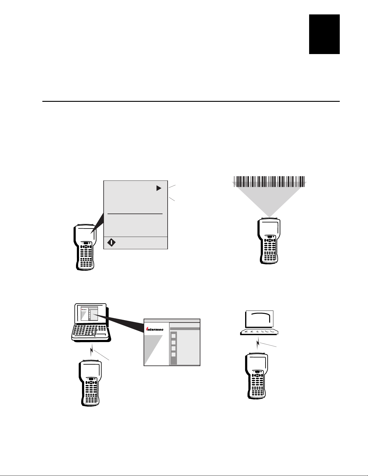
This chapter explains how to configure the 5020 using several different methods. You
will also learn how to configure your 5020 to operate in a network.
How to Configure the 5020
You can configure many operating characteristics of the 5020 Data Collection PC, such
as the bar code symbologies it decodes or the network settings. These characteristics are
controlled by configuration parameters. The values that you set for the configuration
parameters determine how the computer operates.
There are four ways to configure the 5020:
jjjj
Configuring the 5020
39
helveticacondensed
3
Use Utilities on the 5020
Programs
Settings...
Run...
Goto User Mode...
Suspend...
Use Configuration
application.
Or, use
Control
Panel.
Scan Bar Codes
Start
Use Web Browser Use SNMP Commands
Intermec 5020 Configuration Management
TCP/IP
Network
(Ethernet
or RF)
Use browser
and Unit Management
application.
Intermec 5020 Configuration Management
SNMP
Management
Station
TCP/IP
Network
(Ethernet
or RF)
5020U077.eps
3-3
Page 80

5020 Data Collection PC User’s Manual
Helveticcond blk
Use Utilities on the 5020 You can use the Intermec Configuration application or the
Windows CE Control Panel applets on the 5020 to configure all parameters. For help
with the Configuration application, see the next section. For help with the Control
Panel, see Chapter 4, “Customizing the 5020 Using the Control Panel.”
Use Web Browser After the 5020 is communicating with a PC, you can use your Web
browser and the remote Unit Management application to configure all parameters and
manage your 5020. For help, see “Using a Web Browser and the Unit Management
Application” later in this chapter.
Use SNMP Commands After the 5020 is communicating in your network, you can use
an SNMP management station to send SNMP commands to the 5020. For help, see
“Configuring the 5020 by Using SNMP” later in this chapter.
Scan Bar Codes You can scan bar code labels to configure the 5020. However, you
can only configure a subset of the 5020 parameters by scanning bar code labels. For
help and a list of parameters, see “Configuring the 5020 by Scanning Bar Code Labels”
later in this chapter.
39
jjj
Using the Configuration Application on th e 5020
The Configuration application lets you configure the 5020 and view system information.
You can access the Configuration application while running any application. You can
also extend and customize the Configuration application. For help, see Appendix D,
“Extending the Configuration Application.”
To access the Configuration application
1. Press and then press to open the Start menu.
2. Press to highlight Programs and then press # or &. (You can press either Enter
key, # or &, on the 5020.)
3. Press 9 and ! to highlight Configuration and then press &.
3-4
Page 81

Configuring the 5020
jjjj
The Configuration main screen appears, displaying four menu options:
File Choose the File menu to close a menu or screen, apply changes, refresh the
screen to the previous settings, restore factory defaults, and exit the Configuration
application. In addition to the File menu options, each configuration screen has
buttons that you can use to apply changes, refresh the screen, and restore factory
defaults.
39
helveticacondensed
3
Edit The Edit menu options undo, cut, copy, and paste are reserved for future use.
Configure Choose the Configure menu to configure Data Collection, Unit,
Network, and SNMP parameters.
Troubleshoot Choose this option to check the battery status and view terminal
version information. You can check the battery status for the main battery pack and
the bridge battery. The terminal version includes the model number, serial number,
software version, PCB part number, RFID part number, and the last day serviced.
4. To select a menu, press " plus the application menu shortcut. For example, to
select the Configure menu, press " .
5. Use ! and to select a menu option and then press &. For help using the
Configure menu, see the next section.
6. To exit the Configuration application, press " . Press ! to highlight Exit
and then press &.
3-5
Page 82

5020 Data Collection PC User’s Manual
Helveticcond blk
Configuration Parameters at a Glance
39
jjj
File Edit Configure Troubleshoot
Data Collection
Unit
Network
SNMP
Timeout
Scanner
Decode
Options
Virtual
Wedge
Symbologies
Mode
Trigger mode
Redundancy
Selection
Decode security level
Decode priority
Virtual Wedge
Preamble
Postamble
Grid
Code page
Code 39
Interleaved 2 of 5
Code 2 of 5
Codabar
Code 93
Code 11
Code 49
MSI
Code 16K
UPC/EAN
Plessey
Code 128
File Edit Configure Troubleshoot
Data Collection
Unit
Network
SNMP
Protocols
Radio
Ethernet
Advanced
UDP Plus
TFTP
IP address
Name servers
TCP/IP extensions
Radio
DHCP status
IP address
Name servers
DHCP status
Config manager enable
Config subagent enable
UDP Plus enable
File Edit Configure Troubleshoot
Data Collection
Unit
Network
SNMP
Date/Time
Display
Keypad
Powe r
Management
Serial Port
Speaker
Date and Time
Backlight timeout
Backlight level
Key clicks
Caps lock on
Automatic shutoff
IrDA baud rate
Volume
Low beep frequency
High beep frequency
Low beep duration
High beep duration
File Edit Configure Troubleshoot
Data Collection
Unit
Network
SNMP
Read only community string
Security
Traps
Identification
Read/write community string
Read encryption
Write encryption
Encryption key
Authentication
Threshold
Contact
Name
Location
5020U.035
3-6
Page 83

jjjj
Configuring the 5020
39
helveticacondensed
3
Using the Configure Menu
Use the Configure menu to change the configuration settings of your 5020.
To configure the 5020
1. If the Configuration application is not open, press . Choose Programs and
then Configuration.
2. Press " to access the Configure menu. The Configure menu contains
these options:
Data Collection
symbologies, scanner parameters, decode options, and virtual wedge.
Unit
Choose the Unit menu to configure the display, keypad, speaker, serial port,
and power management.
Network
protocols and your radio.
SNMP
traps, and identification.
3. Use ! and to select Data Collection, Unit, Network, or SNMP and then press &.
The configuration screen appears. For example, the Network screen is shown here.
Choose the SNMP menu to configure SNMP parameters such as security,
Choose the Data Collection menu to configure bar code
Choose the Network menu to configure your network settings such as
3-7
Page 84

5020 Data Collection PC User’s Manual
Helveticcond blk
4. Use the 3 (Tab) key and the cursor keys to navigate in the configuration screen.
Make the changes you need for each parameter. For help, see the next section.
5. To save your changes in each configuration screen, press 3 to select the Apply
button and then press &.
6. To exit the Configuration application, press " . Press ! to highlight Exit
and then press &.
7. If you changed any network settings, press ' twice to make the changes effective.
If you changed the UDP Plus enable parameter, warm boot the 5020. For help
booting the 5020, see Chapter 9, “Troubleshooting.”
Navigating in the Configuration Application
Use the instructions in this section to learn how to navigate around the screens, change
parameters, and apply changes. Use this next illustration to get familiar with the
different areas and buttons on each configuration screen.
39
jjj
Configuration
tabs
Focus
Parameter
list
Parameter
options
Start
+
-
X
Current
menu
Buttons
12:50 PM
5020U096.eps
The focus in this illustration is the box around the Date/Time configuration tab and it
indicates that the tab is the active section of the screen. When you move to the
parameter list and parameter options area, the focus changes to highlight the parameter
or option. When you move the focus to a button, the button box has a darker outline.
Here is a quick summary of the keys you use to navigate in the Configuration
application. Detailed instructions are also listed next.
Press To Do This
3
Move the focus from the configuration tab to the parameter list to the parameter
options to the Buttons.
3-8
6 3
Moves the focus in reverse order. For example, you can move from the
parameter options back to the parameter list to change another parameter.
Page 85

Press To Do This
3
$
!
and
Select the next configuration tab. If the focus is on a configuratio n tab, you can
also press
Move up and down within the list of parameters, toggle through the options in a
drop-down list, or move the focus through the options in an option button list.
Configuring the 5020
jjjj
7
or 9 to select the next configuration tab.
39
helveticacondensed
3
9
7
To select another configuration tab
• Press $ 3. Or, if the focus is on the configuration tab, press 7 or 9.
For example, press $ 3 to move the focus from Date/Time to Display and show
the Display parameters.
Note: In the Network menu, you always see the Protocols and Advanced configuration
tabs. If you have a radio or Ethernet PC card installed in the 5020, you will also see a
configuration tab for Radio or Ethernet. For help, see Chapter 9, “Troubleshooting.”
To select a parameter
1. Press 3 until the first parameter in the parameter list area is highlighted.
2. Press or ! to select a parameter.
For example, press 3 to move the focus from the Display tab to the first parameter,
Backlight Timeout.
Expand a parameter list for a parameter that is marked with a plus sign .
Close or collapse a parameter list for a parameter that is marked with a negative
.
sign
3-9
Page 86

5020 Data Collection PC User’s Manual
Helveticcond blk
39
jjj
To expand a parameter list
1. Press 3 to move the focus to the parameter list area.
2. Press or ! to select a parameter that is marked with a plus sign
.
3. Press 9 to expand and display the list of parameters. For example, if the focus is on
the parameter Obtain IP Address via DHCP, press 9 to expand the parameter list.
To close or collapse a parameter list
1. Press or ! to select a parameter that is marked with a negative sign .
2. Press 7 to close the list of parameters. For example, if the focus is on the parameter
Obtain IP Address via DHCP, press 7 to close the parameter list.
To change a parameter
1. Press 3 to move the focus to the parameter list area.
2. Press or ! to select a parameter. If necessary, press 9 to expand a parameter list.
3-10
3. Press 3 to move the focus to the parameter options area.
Page 87

Configuring the 5020
jjjj
4. Change the parameter. There are four types of entry fields:
• Drop-down list
Press or ! to toggle through
the options until the option you
want is highlighted.
• Entry field or box
Type or scan a value. If you are
entering an IP address, use the
or 9 cursor keys to move the
cursor between segments of the
IP address field. To edit the data
in an entry field, use the cursor
keys, 4, or 5.
7
39
helveticacondensed
3
• Check box
Press 4 to check or uncheck
the option.
• Option button list
Press or ! to move the focus
to the option you want to select.
3-11
Page 88

5020 Data Collection PC User’s Manual
Helveticcond blk
5. Repeat Steps 2 through 4 to change another parameter in the same configuration tab.
6. Press 3 to move the focus to the Apply button and then press &. A message box
appears to confirm the changes.
7. Press & to exit the message box.
Using the Refresh Button
You can refresh or reset any parameters until you press the Apply button to save the
changes. A refresh discards all unapplied edits and resets the values to the previous
saved value. A refresh also refetches and synchronizes the values for read-only
parameters like DHCP status and access point name. After you apply changes, you
cannot refresh the parameters to the previous settings. However, read-only parameters
are always updated when you refresh.
To refresh changes
1. Press 3 to move the focus to the Refresh button or choose Refresh from the File
menu.
2. Press & to refresh the parameters in the current screen. A message box appears to
confirm the refresh. For example, if the Scanner configuration screen is displayed
and you choose refresh, the 5020 only refreshes the Scanner parameters.
39
jjj
3. Press & to choose Yes or press 9 to select No and then press &.
4. Press 3 to move the focus to the Apply button and then press &. A message box
appears to confirm the changes.
5. Press & to exit the message box.
Using the Defaults Button
You can set the parameters back to the factory default values. For a list of the default
values, see Appendix A, “5020 Specifications.”
To set the factory defaults
1. Press 3 to move the focus to the Defaults button or choose Restore Factory
Defaults from the File menu.
2. Press & to default the parameters in the curren t scre en. A messag e box appears to
confirm your choice. For example, if the Scanner configuration screen is displayed
and you choose to restore the defaults, the 5020 only sets the Scanner parameters to
the factory defaults.
3. Press & to choose Yes or press 9 to select No and then press &.
4. Press 3 to move the focus to the Apply button and then press &. A message box
appears to confirm the changes.
3-12
5. Press & to exit the message box.
Page 89

jjjj
Configuring the 5020
39
helveticacondensed
3
Using a Web Browser and the Unit Management Application
Use a Web browser and the Unit Management application on your desktop PC to
remotely configure individual 5020 PCs. To access Unit Management on your desktop
PC, you need to connect the 5020 to an Ethernet or RF network. You can configure all
your 5020s on the network from your PC, but you can only configure one at a time. If
you have a desktop PC with Windows NT, you can use Unit Management to configure a
5020 through a serial connection.
To use the Configuration menu in the remote Unit Management application, you need
the Java 1.2 plug-in. You can either automatically download the plug-in during the next
procedure or install the plug-in from the Software Developer’s Kit (SDK) and Support
Files CD-ROM (Part No. 069511).
You can also extend and customize the remote Unit Management application. For help,
see Appendix C, “Extending Remote Unit Management.”
Note: The remote Unit Management application works best with Internet Explorer 4.0
or higher on Windows 95/98/NT. Netscape Navigator 4.0 or higher is also supported on
Windows 95/98/NT. The remote Unit Management application will work on other
platforms such as Unix or Macintosh using Netscape Navigator 4.0 or higher. However,
the installation process and performance of the Java plug-in for Configuration varies by
platform. You may experience some limitations due to browser implementation issues.
For help with the Java plug-in on other platforms, see the Sun Microsystems Web page
at www.java.sun.com/products/plugin.
To connect to the 5020 from your desktop PC
1. Configure the 5020 to communicate using Ethernet or RF communications. If you
are not using a DHCP server, you must configure the IP address and other network
parameters on the 5020. For an RF 5020, you must configure the domain and
security ID. If you have a Windows NT PC and you want to use a serial connection,
you may need to configure the serial port baud rate on the 5020.
For help, see “Configuring for an RF or Ethernet Network” or “Configuring for
Serial or IrDA Communications” later in this chapter.
2. Press ' to turn on the 5020. The 5020 must remain on while you access it through
the remote Unit Management application.
3. Use the D5020 dock or the L5020 adapter to connect the 5020 to AC power. Or,
scan this bar code label to turn off the Automatic Shutoff feature:
Disable Automatic Shutoff
*$+EZ0*
*$+EZ0*
3-13
Page 90

5020 Data Collection PC User’s Manual
Helveticcond blk
Note: The 5020 must be turned on and must remain on while you manage it through
the remote Unit Management application. If you have an RF 5020, it must be in
range of an access point.
4. On your desktop PC, turn off the Active Desktop if you have it enabled. To turn it
off, right-click on the desktop and choose Active Desktop.
For a serial connection on a Windows NT PC, you need to look up the IP address
for your PC’s serial port. In the Programs/Administrative Tools menu, use Remote
Access Administration. From the Server menu, choose Communication Ports and
then select Serial/COM port. Choose the Port Status button. The IP address is in the
Remote Workstation section.
5. On your desktop PC, launch version 4.0 or higher of Internet Explorer or Netscape
Commander.
6. If you access the Internet by using a proxy server, add the IP address to the proxy
server exceptions list for every 5020 you want to manage. Use the Internet options
in your browser to change the proxy server settings.
7. In the browser Address field, type the 5020 IP address or the serial port IP address
that you want to configure and then press Enter:
39
jjj
xxx.xxx.xxx.xxx
where xxx.xxx.xxx.xxx is the IP address of the 5020.
The Unit Management login screen appears on your desktop PC.
3-14
Page 91

Configuring the 5020
jjjj
8. If security is enabled on the 5020, type the password and then click Submit. If security
is not enabled, click Submit. The Unit Management opening screen appears.
39
helveticacondensed
3
9. Click Configuration.
If the Java 1.2 plug-in is not installed on your PC, it automatically downloads now
from the Sun Microsystems Web site. If you choose to download the plug-in, follow
the instructions to download and install it. You can also cancel the download and
install the plug-in from the SDK CD-ROM. Once the plug-in is installed on your
PC, continue with the next step.
The Intermec 5020 Configuration Management screen appears displaying two menu
options:
3-15
Page 92

5020 Data Collection PC User’s Manual
Helveticcond blk
Configure Choose one of the options to configure data collection, unit, network,
and SNMP parameters. You can configure the same parameters using the remote
Configuration Management screen as you do using the Configuration application on
the 5020. For a list of parameters available in each menu, see the “Configuration
Parameters at a Glance” illustration earlier in this chapter.
Troubleshoot Choose this option to check the battery status and view terminal
version information. You can check the battery status for the main battery pack and
the bridge battery. The terminal version includes the model number, serial number,
software version, PCB part number, RFID part number, and the last day serviced.
Note: Do not resize or refresh the Intermec 5020 Configuration Management
windows until the web page is completely loaded. If you do resize the window, wait
for the web page to refresh and finish loading before you resize or refresh again.
10. Click Data Collection, Unit, Network, SNMP, or Troubleshoot. For example, click
Unit.
Note: In the Network menu, you always see the Protocols and Advanced
configuration tabs. If you have a radio or Ethernet PC card installed in the 5020,
you will also see a configuration tab for Radio or Ethernet. For help, see Chapter 9,
“Troubleshooting.”
39
jjj
11. Click the configuration tab. For example, click Display.
12. Click the parameter you want to change. You may need to click
to expand a
parameter list. The parameter options appear in the lower part of the screen.
13. Change the parameter by clicking an option or check box, selecting from a dropdown list, or typing the new value in the entry field.
14. To save your changes in each configuration screen, click the Apply button.
15. Click Unit and then click Power Management. If necessary, reset the Automatic
Shutoff to preserve battery power on the 5020. For help, see “Automatic Shutoff” in
Chapter 8.
16. To exit the Configuration Management screen, click another option from the Unit
Management menu or exit your Web browser.
17. If you changed any network settings, press ' twice on the 5020 to have the
changes take effect. If you changed the UDP Plus enable parameter, warm boot the
5020. For help booting the 5020, see Chapter 9, “Troubleshooting.”
You can also use the Refresh and Defaults buttons in the Configuration Management
screens. For help, see “Using the Refresh Button” and “Using the Defaults Button”
earlier in this chapter.
3-16
Page 93

jjjj
Configuring the 5020 by Using SNMP
The 5020 is an SNMP-enabled device. You can use an SNMP management station to
control and configure the 5020 anywhere on an SNMP enabled network.
The 5020 supports proprietary Management Information Bases (MIBs). You will find
the MIB files for the 5020 in these two places:
• on the Software Developer’s Kit (SDK) and Support Files CD-ROM (Part No.
069511) that shipped with this manual
• on www.intermec.com
There are six MIB files:
MIB File Description
intermec.mib Defines the root of the Intermec MIB tree.
itcadc.mib Defines objects for Automated Data Collection. For example, bar code
symbologies.
itcfile.mib Defines objects for manipulating and viewing files. For example, TFTP
Timeout.
Configuring the 5020
39
helveticacondensed
3
itcnetwork.mib Defines objects for Network parameters. For example, 5020 IP address.
itcsnmp.mib Defines objects for Intermec SNMP parameters and security methods.
For example, SNMP security IP address.
itcterminal.mib Defines objects for terminal parameters. For example, keypad clicker.
In addition to the MIB files, Intermec provides SNMP support for MIB II through seven
read-only MIB II (RFC1213-MIB) OIDs. You can only query these seven OIDs through
an SNMP management station. The OIDs are not available in the Configuration
application nor the remote Unit Management application.
The seven read-only MIB II OIDs are listed and defined in the next table.
MIB II Item OID Group or Table Description
ifNumber 1.3.6.1.2.1.2.1.0 Interfaces group Indicates the number of adapters
present in the system. For the 5020, if
one adapter is present in the system,
then ifNumber = 1 and ifIndex = 1.
ifIndex 1.3.6.1.2.1.2.2.1.1.ifIndex Interfaces table
(ifTable)
ifDescr 1.3.6.1.2.1.2.2.1.2.ifIndex Interfaces table
(ifTable)
A unique value for each interface. The
value ranges between 1 and the value of
ifNumber.
A textual string c ontaining information
about the interface.
3-17
Page 94

5020 Data Collection PC User’s Manual
39
jjj
Helveticcond blk
Read-Only MIB II OIDs (continued)
MIB II Item OID Group or Table Description
ifType 1.3.6.1.2.1.2.2.1.3.ifIndex Interfaces table
(ifTable)
ipAdEntAddr 1.3.6.1.2.1.4.20.1.1.IpAddress IP address table
(ipAddrTable)
ipAdEntIfIndex 1.3.6.1.2.1.4.20.1.2.IpAddress IP address table
(ipAddrTable)
ipAdEntNetMask 1.3.6.1.2.1.4.20.1.3.IpAddress IP address table
(ipAddrTable)
The community string allows an SNMP manager to manage the 5020 with a specified
privilege level. The default read only community string is “public.” The default
read/write community string is “private.”
To configure the 5020 using SNMP
An integer containing infor mation
about the type of the interface. It is
equal to 1 for Other.
The IP address to which this entry’s
addressing information pert ains (same
as 5020 IP address).
Where IpAddress is the user’s entered
valid non-zero IP address of the 5020,
for example, 10.20.10.152.
The index value that uniquely identifies
the interface to which this entry is
applicable (same as ifIndex).
The subnet mask associated with the IP
address of this entry (same as Subnet
Mask).
1. Use the Configuration application or the Unit Management application to configure
your 5020s for RF or Ethernet communications.
2. Determine the OID (Object Identifier) for the parameter that you want to change.
The Intermec base OID is:
1.3.6.1.4.1.1963
3. Use your SNMP management station to get and set variables that are defined in the
Intermec MIBs.
You can set the traps, identification, or security configuration parameters for SNMP.
For help, see Chapter 8, “Configuration Command Reference.”
3-18
Page 95

Configuring the 5020
jjjj
39
helveticacondensed
Configuring the 5020 by Scanning Bar Code Labels
You can configure the 5020 by scanning bar code labels listed in this manual or by
creating your own Code 39 or Code 93 bar code labels. For a list of configuration bar
codes, see Chapter 8, “Configuration Command Reference.”
Here are the commands that you can configure using bar code labels:
• Automatic Shutoff • Display Backlight Timeout
• Beep Duration • Interleaved 2 of 5
• Beep Frequency • Keypad Caps Lock
• Beep (Speaker) Volume • Keypad Clicker
• Codabar • MSI
• Code 11 • Plessey
• Code 16K • Postamble
• Code 2 of 5 • Preamble
3
• Code 39 • Scanner Mode
• Code 49 • Scanner Redundancy
• Code 93 • Scanner Selection
• Code 128 • Scanner Timeout
• Decode Priority • Scanner Trigger
• Decode Security • UPC/EAN
You need to configure all other commands using the Configuration application, the Unit
Management application, or SNMP.
For example, you can use the Beep (Speaker) Volume configuration command to adjust
the volume of the computer’s audio signals. You can scan this bar code label to set the
speaker volume to a very quiet audio level:
Set Beep Volume to Very Quiet
*$+BV1*
*$+BV1*
When you scan bar code configuration commands, the 5020 sounds an audio signal
unless the beep volume is turned off. There are two beep sequences:
• Low beep, low beep, high beep, high beep means you scanned a valid configuration
command.
• Three low beeps means you scanned an invalid configuration command.
3-19
Page 96

5020 Data Collection PC User’s Manual
Helveticcond blk
You can create bar code labels that contain more than one configuration command. For
example, you can create one bar code label to configure the computer for:
• One-Shot Scanner mode (SB0)
• Scanner Redundancy set to high (SR2)
One-Shot Scanner Mode, Set Scanner Redundancy to High
*$+SB0SR2*
*$+SB0SR2*
When you create bar code labels to set one or more configuration commands, follow
these rules:
• The bar code label must be printed using Code 39 or Code 93 symbology.
• The bar code label must include the start and stop character. Most bar code printing
utilities automatically include the start and stop character.
• The bar code label must start with $+ (Change Configuration command).
• Each configuration command must include the command syntax and the value for
the command. For example, BV is the command syntax for Beep Volume and the
value 4 sets the speaker volume to loud.
39
jjj
• Each configuration command in a concatenated bar code label must begin with the
same character. For example, SB and SR can be set in a single bar code label.
• If you set one configuration command to a string of ASCII characters and another
configuration command follows, you must enclose the value in quotes. If you do not
include the quotation marks, the computer will interpret everything after the first
command as data and will not find the second configuration command.
For example, to set the preamble to BV, use $+ADBV (no quotes are needed). To
set the preamble to BV and turn off the beep volume, use $+AD"BV"BV0, or
change the order and use $+BV0ADBV. To clear the preamble and postamble from
a single label, use $+AD""AE.
• To include quotation marks when you set a value, the entire value must be enclosed
in quotation marks. Type two sets of quotation marks ("") to include one quotation
mark as the value for a command. For example, to set the preamble to ABC"D, use
$+AD"ABC""D".
3-20
Page 97

Configuring the 5020
jjjj
39
helveticacondensed
Configuring the 5020 to Operate in a Network
The 5020 Data Collection PC is a versatile hand-held device that you can easily add to
your network. You can use the 5020 as an end device in your wired or 2.4 GHz RF
network.
There are several ways to connect the 5020 to your network:
• On an RF 5020, use the radio to communicate with other RF devices in your
network.
• On a batch 5020, use an Ethernet PC card (purchased separately) to communicate
with other devices in your network.
• Use the IrDA port or a serial PC card (purchased separately) to transfer data
between the 5020 and a host computer.
To configure your 5020 for an RF or Ethernet network, start with the instructions in the
next section. To configure and use your IrDA port, see “Configuring for Serial or IrDA
Communications” lat er in thi s chapte r.
3
Configuring for an RF or Ethernet Network
The 5020 communicates over an RF or Ethernet network using either of these network
protocol options:
• TCP/IP
• UDP Plus
The 5020 ships with TCP/IP protocol enabled. In a TCP/IP network, the 5020
communicates directly through the access points or through the Ethernet network to the
host or server.
UDP Plus is an Intermec protocol built on top of the User Datagram Protocol (UDP). It
maximizes the performance of wireless (RF) networks and provides robust data
communications. In a UDP Plus network, the 5020 communicates through the DCS 300
to the host or server. If you have a DCS 300 network, you must enable UDP Plus on the
5020 PC.
3-21
Page 98

5020 Data Collection PC User’s Manual
Helveticcond blk
5020 in RF and Ethernet Networks
39
jjj
TCP/IP
5020 5020
Access point
5020 5020
Host
Ethernet
5020U095.eps
UDP Plus
5020 5020
Access point
DCS 300
5020 5020
3-22
The next sections explain how to configure the network parameters (RF or Ethernet),
radio parameters, and UDP Plus network parameters.
Configuring the Network Parameters
The network parameters you need to set depend on your network environment. If you
are using a DHCP (Dynamic Host Control Protocol) server, the 5020 broadcasts a
message to the server and the DHCP server assigns these network parameters:
• IP address
• Subnet mask
• Default router
• Primary and secondary DNS servers
• Primary and secondary WINS servers
DHCP is automatically enabled on the 5020. If you are not using a DHCP server, you
need to disable DHCP and set the parameters listed above. You only need to set the
DNS and WINS servers if they are required for your network communications.
Page 99

Configuring the 5020
jjjj
If you are on a network that uses a WINS server or you want to use universal naming
conventions (UNC) such as \\computer_name\share_name\filename, you need to set the
device name. Follow the next instructions to configure the network parameters and then
set the device name. For help with the device name, see “Set Communications
Properties” in Chapter 4.
To configure the network parameters on the 5020
1. If you have a batch 5020, install an Ethernet PC card. For help, see “Using PC
Cards” in Chapter 2.
2. Use the Configuration application to configure the 5020. To open the Configuration
application, press . Choose Programs and then Configuration.
If you are using a DHCP server, you may not need to configure any additional
parameters. Follow the next instructions to view the network parameters and check
the DHCP status.
3. Press " to access the Configure menu.
4. Press ! to select Network and
then press &. The Network
configuration screen appears.
39
helveticacondensed
3
5. For an RF 5020, press 9 to select
the Radio tab. For a batch 5020
with an Ethernet PC card, press
twice to select the Ethernet tab.
Use the illustrations on the next
page to find the Radio or Ethernet
parameters. For a definition of
each parameter, see Chapter 8,
“Configuration Command
Reference.”
6. Choose IP address to set DHCP, IP address, subnet mask, and default router. If you
are not using a DHCP server, you must uncheck or disable the Obtain IP Address
via DHCP parameter and then set the IP address and other network parameters.
If you are using a DHCP server, choose DHCP Status to check the IP and server
assignments for the 5020. Select the Refresh button to see the current assignments.
If you have an RF 5020, you may not see any data until you set the radio parameters
in the next section.
Use the 3 (Tab) key and the cursor keys to navigate in the configuration screen.
Make the changes you need for each parameter. For help, see “Navigating in the
Configuration Application” earlier in this chapter.
9
3-23
Page 100

5020 Data Collection PC User’s Manual
Helveticcond blk
Radio and Ethernet Parameters
39
jjj
File Edit Configure Troubleshoot
Data Collection
Unit
Network
SNMP
IP address
Radio
Name servers
TCP/IP extensions
Radio
DHCP status
5020U074.eps
Obtain IP address via DHCP
IP address
Subnet mask
Default router
Primary DNS
Secondary DNS
Primary WINS
Secondary WINS
Receive window size
Initial round trip time
Delayed ACK timer
Access Pt name
Access Pt MAC address
Radio ROM version
Radio MAC address
Roaming allowed
Security ID
Transmit mode
Domain
Inactivity timeout
IP address
Subnet mask
Default router
DNS servers
WINS servers
File Edit Configure Troubleshoot
Data Collection
Unit
Network
SNMP
IP address
Ethernet
Name servers
DHCP status
5020U075.eps
Obtain IP address via DHCP
IP address
Subnet mask
Default router
Primary DNS
Secondary DNS
Primary WINS
Secondary WINS
IP address
Subnet mask
Default router
DNS servers
WINS servers
3-24
7. To save your changes, press 3 to select the Apply button and then press &.
8. Choose Name Servers to set the Primary and Secondary DNS and WINS servers.
Make the changes you need for each parameter.
9. To save your changes, press 3 to select the Apply button and then press &.
10. Use the next table to continue configuring your 5020.
Type of 5020 Protocol What to do next
RF 5020 TCP/IP Skip the next steps and continue with the next
section, “Configuring the Radio Parameters.”
UDP Plus Skip the next steps and continue with the next
section, “Configuring the Radio Parameters.”
Then, use “Configuring UDP Plus Protocol for a
DCS 300 Network” later in this chapter.
Ethernet PC Card TCP/IP Continue with Step 11.
UDP Plus Skip the next steps and continue with
“Configuring UDP Plus Protocol for a DCS 300
Network” later in this chapter.
 Loading...